WO2024053002A1 - 携帯情報端末、端末本体、およびアタッチメント - Google Patents
携帯情報端末、端末本体、およびアタッチメント Download PDFInfo
- Publication number
- WO2024053002A1 WO2024053002A1 PCT/JP2022/033517 JP2022033517W WO2024053002A1 WO 2024053002 A1 WO2024053002 A1 WO 2024053002A1 JP 2022033517 W JP2022033517 W JP 2022033517W WO 2024053002 A1 WO2024053002 A1 WO 2024053002A1
- Authority
- WO
- WIPO (PCT)
- Prior art keywords
- attachment
- terminal
- image
- information terminal
- mobile information
- Prior art date
Links
- 238000004891 communication Methods 0.000 claims description 35
- 230000001133 acceleration Effects 0.000 claims description 12
- 230000007246 mechanism Effects 0.000 claims description 5
- 230000002093 peripheral effect Effects 0.000 claims description 5
- 238000005516 engineering process Methods 0.000 abstract description 4
- 230000006870 function Effects 0.000 description 54
- 238000000034 method Methods 0.000 description 37
- 238000001514 detection method Methods 0.000 description 34
- 238000010586 diagram Methods 0.000 description 30
- 230000008569 process Effects 0.000 description 29
- 230000003287 optical effect Effects 0.000 description 28
- 238000012545 processing Methods 0.000 description 28
- 230000004048 modification Effects 0.000 description 25
- 238000012986 modification Methods 0.000 description 25
- 238000005259 measurement Methods 0.000 description 20
- 238000003860 storage Methods 0.000 description 16
- 238000012937 correction Methods 0.000 description 15
- 230000005484 gravity Effects 0.000 description 11
- 238000010295 mobile communication Methods 0.000 description 11
- 230000017531 blood circulation Effects 0.000 description 6
- 230000008859 change Effects 0.000 description 6
- 230000000694 effects Effects 0.000 description 5
- 238000005286 illumination Methods 0.000 description 3
- 239000004973 liquid crystal related substance Substances 0.000 description 3
- 238000003672 processing method Methods 0.000 description 3
- 238000006243 chemical reaction Methods 0.000 description 2
- HBBGRARXTFLTSG-UHFFFAOYSA-N Lithium ion Chemical compound [Li+] HBBGRARXTFLTSG-UHFFFAOYSA-N 0.000 description 1
- 238000012356 Product development Methods 0.000 description 1
- 230000005540 biological transmission Effects 0.000 description 1
- 210000004204 blood vessel Anatomy 0.000 description 1
- 239000000470 constituent Substances 0.000 description 1
- 238000009826 distribution Methods 0.000 description 1
- 238000003702 image correction Methods 0.000 description 1
- 238000003384 imaging method Methods 0.000 description 1
- 230000006872 improvement Effects 0.000 description 1
- 229910001416 lithium ion Inorganic materials 0.000 description 1
- 230000007774 longterm Effects 0.000 description 1
- 238000004519 manufacturing process Methods 0.000 description 1
- 238000000691 measurement method Methods 0.000 description 1
- 239000000203 mixture Substances 0.000 description 1
- 230000005855 radiation Effects 0.000 description 1
- 230000004044 response Effects 0.000 description 1
- 230000000630 rising effect Effects 0.000 description 1
- 239000004065 semiconductor Substances 0.000 description 1
- 230000007480 spreading Effects 0.000 description 1
- 238000003892 spreading Methods 0.000 description 1
- 210000000707 wrist Anatomy 0.000 description 1
Images


Classifications
-
- G—PHYSICS
- G09—EDUCATION; CRYPTOGRAPHY; DISPLAY; ADVERTISING; SEALS
- G09G—ARRANGEMENTS OR CIRCUITS FOR CONTROL OF INDICATING DEVICES USING STATIC MEANS TO PRESENT VARIABLE INFORMATION
- G09G5/00—Control arrangements or circuits for visual indicators common to cathode-ray tube indicators and other visual indicators
- G09G5/36—Control arrangements or circuits for visual indicators common to cathode-ray tube indicators and other visual indicators characterised by the display of a graphic pattern, e.g. using an all-points-addressable [APA] memory
Definitions
- the present invention relates to a mobile information terminal, a terminal body, and an attachment.
- a smartwatch is equipped with a touch screen, various control devices, sensors, etc. For example, by touching and operating characters or icons displayed on the touch screen, the user can display various biological information such as heart rate measured by a sensor, display the status of email reception, etc. You can use the functions of
- Patent Document 1 describes the following electronic device.
- the casing of the electronic device has a first part located on the front side of the casing, a second part located on the side surface of the casing, a first band attachment part, and a second band attachment part.
- the second part has the function of displaying images.
- the first band attachment portion is located on the side surface located on the upper side when viewed from the front side of the housing.
- the second portion and the second band attachment portion are located on a side surface located on the lower side when viewed from the front side of the housing.
- the first part has a function of displaying an image, or has at least one of an hour hand, a minute hand, and a second hand. Such a configuration makes it easier for the user to read the displayed information.
- the electronic device described in Patent Document 1 has a configuration in which a small display section is mounted on the side surface of the housing. Therefore, for example, when a user wearing an electronic device wants to share the displayed information with someone other than the user, the visibility of the information for those other than the user is not considered. . Further, for example, simply adding a second display screen to a narrow side of an electronic device cannot be said to be sufficiently user-friendly even when the user wants to view a lot of information. That is, there is room for improvement in the visibility of displayed information.
- One of the representative embodiments of the present invention is a mobile information terminal worn on the arm, which includes a terminal body and an attachment that is attached to the terminal body and communicably connected to the terminal body.
- the attachment includes a projector section that projects an image based on image information obtained from the terminal main body, and is configured such that a projection opening direction of the projector section is variable with respect to the terminal main body.
- the terminal main body or the attachment specifies a state of the mobile information terminal including the position of the attachment with respect to the terminal main body, and the terminal main body or the attachment determines the projection of the image based on the specified state. It is a mobile information terminal that performs control.
- One of the typical embodiments of the present invention is a terminal main body constituting a mobile information terminal worn on the arm, the terminal main body having a projector section for projecting an image, and the projection opening direction of the projector section being directed to the main body.
- a mechanism for attaching an attachment that is configured to be variable with respect to the attachment; a communication unit that exchanges information with the attachment; a generating unit that generates image information to be transmitted to the attachment via the communication unit;
- the terminal main body includes an acquisition unit that acquires information representing a direction of a projection port from an attachment, and edits the image information based on the information acquired by the acquisition unit.
- One of the typical embodiments of the present invention is an attachment constituting a mobile information terminal worn on the arm, the attachment being attached to the main body of the mobile information terminal, communicably connected to the main body, It has a projector section that projects an image based on image information obtained from the main body, and is configured such that the direction of the projection opening of the projector section is variable with respect to the main body, and the main body or the attachment A state of the portable information terminal including a position of the attachment relative to the main body is specified, and the main body or the attachment is an attachment that controls projection of the image based on the specified state.
- FIG. 1 is a front view of a portable information terminal according to Embodiment 1.
- FIG. 1 is a side view of a portable information terminal according to Embodiment 1.
- FIG. 2 is a cross-sectional view taken along line AA of the portable information terminal shown in FIG. 1.
- FIG. FIG. 3 is a front view of the terminal main body as seen from the display surface side. 4 is a sectional view taken along line BB of the terminal body shown in FIG. 3.
- FIG. FIG. 3 is a front view of the attachment. 6 is a sectional view taken along line CC of the attachment shown in FIG. 5.
- FIG. 6 is a sectional view taken along line DD of the attachment shown in FIG. 5.
- FIG. FIG. 3 is a rear view of the attachment.
- FIG. 3 is a timing chart of output signals obtained by a pattern detection sensor.
- FIG. 3 is a rear view of the mobile information terminal.
- FIG. 2 is a diagram illustrating an example of the hardware configuration of a terminal body. It is a figure showing an example of composition of a projector part in an attachment.
- FIG. 3 is a flow diagram showing initialization processing when an attachment is attached. It is a figure which shows the example of a display of a message.
- FIG. 1 is a front view of a portable information terminal according to a first embodiment.
- FIG. 1 is a side view of a portable information terminal according to a first embodiment.
- FIG. 7 is a front view of a portable information terminal according to a second embodiment.
- FIG. 3 is a side view of a portable information terminal according to a second embodiment.
- FIG. 7 is a front view of a portable information terminal according to a third embodiment.
- FIG. 7 is a side view of a portable information terminal according to a third embodiment.
- FIG. 7 is a front view of a portable information terminal according to a fourth embodiment.
- FIG. 7 is a side view of a portable information terminal according to a fourth embodiment.
- FIG. 7 is a front view of a portable information terminal according to a fifth embodiment.
- FIG. 7 is a front view of a portable information terminal according to a sixth embodiment.
- FIG. 7 is a side view of a portable information terminal according to a sixth embodiment.
- FIG. 7 is a front view of a portable information terminal according to a seventh embodiment.
- FIG. 7 is a front view of a portable information terminal according to an eighth embodiment.
- FIG. 7 is a side view of a portable information terminal according to an eighth embodiment.
- FIG. 7 is a front view of a portable information terminal according to a ninth embodiment. It is a figure which shows an example of a setting information table.
- FIG. 3 is a diagram showing an example of detailed contents of a setting information table. It is a figure showing the table which shows an example of the correspondence of an attachment rotation position and an attachment rotation angle.
- FIG. 7 is a diagram illustrating a table showing an example of the correspondence between the terminal main body posture, the inclination direction and the upward inclination angle of the terminal main body. It is a figure which shows an example of the content of the setting information matched in the setting information table.
- FIG. 3 is a diagram showing an example of detailed contents of a setting information table.
- FIG. 7 is a diagram illustrating a table showing an example of the correspondence between the terminal main body posture, the inclination direction and the upward inclination angle of the terminal main body. It is a figure which shows an example of the
- FIG. 7 is a flow diagram illustrating an example of a process for automatically determining whether the arm on which the mobile information terminal is attached is left or right.
- FIG. 7 is a flow diagram illustrating an example of a process for determining the inner and outer sides of the arm on which the mobile information terminal is attached.
- FIG. 2 is a flow diagram illustrating an example of processing related to projection of display content on a mobile information terminal.
- 7 is a front view of a portable information terminal according to a first modification of the first embodiment.
- FIG. FIG. 3 is a side view of a portable information terminal according to a first modification of the first embodiment.
- 7 is a diagram illustrating an example of a portable information terminal according to a first modification of the first embodiment.
- FIG. 34 is a diagram showing a modification example of the embodiment of the portable information terminal shown in FIG. 33.
- FIG. It is a figure which shows an example of a setting information table.
- FIG. 3 is a diagram showing an example of detailed contents of a setting information table.
- FIG. 7 is a front view of a portable information terminal according to a second modification of the first embodiment.
- FIG. 7 is a side view of a portable information terminal according to a second modification of the first embodiment.
- FIG. 3 is a diagram showing a configuration example of a mobile information terminal according to Embodiment 2.
- FIG. FIG. 7 is a diagram showing a portable information terminal that is a first modification of the second embodiment.
- Embodiment 1 A portable information terminal according to Embodiment 1 will be described.
- the portable information terminal according to the first embodiment has a function of projecting an image or a moving image (hereinafter also simply referred to as an image) as display content.
- the mobile information terminal according to the first embodiment is, for example, a so-called wristwatch type that is worn on the user's arm.
- the configuration of the mobile information terminal according to Embodiment 1 will be described.
- FIG. 1A is a front view of mobile information terminal 10 according to the first embodiment.
- FIG. 1B is a side view of the mobile information terminal 10 according to the first embodiment.
- the upward direction is the front direction F
- the downward direction is the rear direction B.
- the rightward direction is the rightward direction R
- the leftward direction is the leftward direction L
- the forward direction is the upward direction U
- the forward direction is the downward direction D.
- the mobile information terminal 10 mainly includes a terminal main body 11 and an attachment 21.
- the terminal main body 11 has a circumferential peripheral edge.
- the terminal main body 11 also includes a housing 12, a touch screen section 13, a mark section 14, a belt 17, and a home button 191 as constituent elements.
- the casing 12 corresponds to a so-called housing of the terminal main body 11, and generally has a cylindrical shape with a short column axis length or a thick disk shape.
- the touch screen section 13 is provided on the surface of the housing 12, and has, for example, a rectangular shape or a disk shape.
- the touch screen section 13 has a structure in which a display section and an input section are integrated.
- the display section displays time, biological information, and other information, and is composed of display elements such as a liquid crystal panel and organic EL.
- the input unit accepts a touch operation by a user, and is configured with a capacitive touch sensor or the like.
- the mark portion 14 is arranged in a specific direction and position on the housing 12, and functions as a mark.
- the mark portion 14 is a triangular mark, and is located in the 12 o'clock direction of a typical wristwatch.
- the belt 17 is connected to the housing 12 and is for wrapping around the user's arm so that the mobile information terminal 10 is worn on the user's arm.
- the home button 191 is a physical button provided separately from the touch screen section 13 on the display surface side of the touch screen section 13 of the housing 12.
- the home button 191 is used, for example, to return displayed information to the main menu screen.
- the attachment 21 is configured to be detachable from the circumferential edge forming the side surface of the housing 12. Further, the attachment 21 is configured to be rotatable relative to the housing 12 when attached to the peripheral edge of the housing 12. Further, the attachment 21 is configured to be able to communicate with the terminal main body 11.
- the attachment 21 mainly includes a bezel section 213 and a projector section 22.
- the bezel portion 213 is configured to be attachable to the peripheral edge of the housing 12. Furthermore, when the bezel portion 213 is attached to the peripheral edge of the housing 12, it becomes an annular frame portion surrounding the display screen of the touch screen portion 13, and is configured to be rotatable with respect to the housing 12.
- the projector section 22 is provided on the bezel section 213 so as to be configured integrally with the bezel section 213.
- the projector unit 22 has a function of projecting an image representing display content onto an object such as the back of a hand, a wall, or a desk.
- a projection aperture 25 is formed in the projector section 22, and the projection light 10p is projected from the projection aperture 25 so as to spread toward the projection aperture direction PA, which is the central axis direction of the opening of the projection aperture 25. Note that details of the configuration of the attachment 21 will be described later.
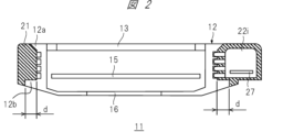
- FIG. 2 is a cross-sectional view of the portable information terminal 10 shown in FIG. 1 taken along the line AA.
- FIG. 2 shows a state in which the attachment 21 is attached to the housing 12. Further, in FIG. 2, the shaded area represents a cross section of the attachment 21.
- the mobile information terminal 10 has a physical information measurement sensor 16.
- the physical information measurement sensor 16 is arranged so as to touch the user's skin when the mobile information terminal 10 is worn on the user's arm.
- the physical information measurement sensor 16 has a function of measuring the user's pulse rate, electrocardiogram, blood flow, etc., and outputs a signal according to the measurement results.
- the housing 12 has a display surface side protrusion 12a and a sensor side protrusion 12b.
- the display surface side convex portion 12a is formed along the circumferential direction on the display surface side of the touch screen portion 13, and is a convex portion having a tapered shape.
- the sensor side convex portion 12b is a convex portion that is formed along the circumferential direction on the side of the housing 12 where the physical information measurement sensor 16 is disposed, and has a width d in the radial direction. In this way, by forming the inner circumferential side of the bezel portion 213 to follow the circumferential shape of the housing 12, the mobile information terminal 10 is configured so that the bezel portion 213 does not come off from the housing 12. .
- the portable information terminal 10 has a control board 15 inside the housing 12.
- the control board 15 controls the system of the mobile information terminal 10, the display of the touch screen section 13, and the image projected from the projector section 22 of the bezel section 213.
- the mobile information terminal 10 has an internal space 22i inside the casing of the projector section 22 provided in the bezel section 213.
- the internal space 22i houses a control board 27 of the projector unit 22, which will be described in detail later, a projection optical system (not shown), and the like.
- FIG. 3 is a front view of the terminal main body 11 viewed from the display surface side. That is, FIG. 3 shows a state in which the bezel portion 213 of the mobile information terminal 10 is removed.
- the housing 12 of the terminal body 11 is provided with pattern detection sensors 12c and 12d.
- the pattern detection sensors 12c and 12d emit light and detect the amount of reflected light according to the pattern of the reflecting surface of the emitted light. Details of the operation of these pattern detection sensors 12c and 12d will be described later.
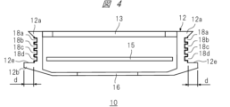
- FIG. 4 is a sectional view taken along line BB of the terminal main body 11 shown in FIG. 3.
- a plurality of grooves are formed along the circumferential side of the housing 12, and slip rings 18a to 18d are provided in these grooves.
- the bezel portion 213 rotatably fits into the slip rings 18a to 18d, and the bezel portion 213 and the slip rings 18a to 18d are configured to be electrically connectable.
- Each slip ring 18a-18d is electrically insulated between each other.
- the slip rings 18a and 18d are assigned as terminals for supplying power from the power supply included in the terminal body 11 to the bezel part 213 side
- the slip rings 18b and 18c are assigned as terminals for supplying power from the power supply included in the terminal body 11 to the bezel part 213 side
- the slip rings 18b and 18c are assigned as terminals for supplying power from the power supply included in the terminal body 11 to the bezel part 213 side
- the slip rings 18b and 18c are It is assigned as a terminal for transmitting and receiving signals to and from the bezel portion 213.
- a housing-side bezel back contact surface 12e is formed on the sensor-side convex portion 12b.
- the pattern detection sensors 12c and 12d are arranged on the case side bezel back contact surface 12e.
- the case side bezel back contact surface 12e has a width d in the radial direction of the bezel portion 213.
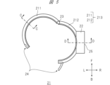
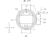
- FIG. 5 is a front view of the attachment 21.
- the bezel portion 213 includes a first semicircular part 211, a second semicircular part 212, a pin 23, and a fastener 24.
- the first semicircular part 211 and the second semicircular part 212 each have a generally semicircular shape, and a through hole is formed at one end in the circumferential direction.
- the pin 23 is inserted into the through holes of the first semicircular part 211 and the second semicircular part 212 in a state where these holes are overlapped, and the pin 23 is inserted into the through holes of the first semicircular part 211 and the second semicircular part 212 .
- the fastener 24 connects the first semicircular part 211 and the second semicircular part 212 when the first semicircular part 211 and the second semicircular part 212 are closed. It is to be fixed in place.
- the projector section 22 is provided near the center of the outer periphery of the second semicircular part 212 so as not to interfere with the terminal main body 11, and is configured integrally with the first semicircular part 211.
- the projector section 22 is configured to project projection light so that display content such as an image or a moving image representing characters, figures, images, etc. is projected onto an object.
- the projection aperture 25 is provided on the side surface of the projector section 22, and is an optical aperture onto which the projection light 10p is projected. Therefore, the projector section 22 integrated with the bezel section 213 can rotate together with the bezel section 213, and the spreading direction of the projection light 10p from the projector section 22 can be freely changed by 360 degrees.
- the first semicircular part 211 and the second semicircular part 212 are connected by the fastener 24 in a closed state surrounding the side surface of the housing 12, so that the bezel part 213 is connected to the terminal main body 11.
- the attachment 21 can be attached to and detached from the terminal main body 11.
- FIG. 6 is a cross-sectional view of the attachment 21 shown in FIG. 5 taken along line CC.
- a main body side bezel back contact surface 21b is formed to be in contact with the body side bezel back contact surface 12e (FIG. 4).
- the main body side bezel back contact surface 21b has a width d in the radial direction of the bezel portion 213.
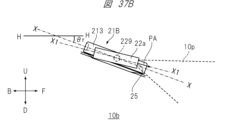
- FIG. 7 is a sectional view taken along the line DD of the attachment 21 shown in FIG. 5.
- Terminals 26a to 26d are provided in the portions of the first semicircular part 211 and the second semicircular part 212 where the projector section 22 is provided.
- the terminals 26a to 26d respectively come into contact with the slip rings 18a to 18d and are electrically connected.
- Such a configuration makes it possible to supply power from the power supply inside the housing 12 to the bezel part 213 and to transmit and receive signals between the housing 12 and the bezel part 213.
- the power supplied to the bezel section 213 is also supplied to the control board 27 and the like inside the projector section 22.
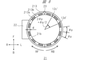
- FIG. 8 is a rear view of the attachment 21.
- a first light reflecting surface 213a shown with diagonal lines is provided on the surface of the main body side bezel back surface contact surface 21b that has a width d in the radial direction of the bezel portion 213 and extends along the circumference.
- a pattern is formed in which second light reflecting surfaces 213b indicated by diagonal lines are alternately arranged at angular intervals of ⁇ p.
- the first light reflecting surface 213a and the second light reflecting surface 213b have different light reflectances. In this embodiment, it is assumed that the light reflectance is greater than the second light reflecting surface 213b>the first light reflecting surface 213a.
- the position of the pattern detection sensor 12c (FIG. 3) when the attachment 21 is attached to the terminal body 11 is represented by position 12c'
- the position of the pattern detection sensor 12c (FIG. 3) when the attachment 21 is attached to the terminal body 11 is also represented by position 12c'
- the position of 12d (FIG. 3) is represented by position 12d'.
- FIG. 9 is a timing chart of output signals obtained by the pattern detection sensor.
- the timing chart shown in FIG. 9 shows output signals obtained by the pattern detection sensor 12c and the pattern detection sensor 12d when the attachment 21 rotates with respect to the terminal main body 11.
- the horizontal axis represents the elapsed time t.
- the detection signal of the pattern detection sensor 12c and the detection signal of the pattern detection sensor 12d are set to the "H (high)" level on the second light reflecting surface 213b, which has a relatively high reflectance, and to the "H" level on the second light reflecting surface 213b, which has a relatively low reflectance.
- the first light reflecting surface 213a outputs "L (low)".
- the output signal of the pattern detection sensor 12c becomes a pulse whose rising timing from the "L" level to the "H” level is earlier than the signal output of the pattern detection sensor 12d.
- the output signal of the pattern detection sensor 12c rises from the "L” level to the "H” level at the timing shown in FIG. The pulse is slower than the signal output from the pattern detection sensor 12d.
- the rotation angle of the bezel portion 213 with respect to the terminal body 11 can be determined by the number of pulses of the output of the pattern detection sensor 12c and the pattern detection sensor 12d, that is, the number of changes in the H level and L level. Further, the rotating direction of the bezel portion 213 is the RF direction if the signal output of the pattern detection sensor 12c is at the "H" level when the output signal of the pattern detection sensor 12d rises from the "L" level to the "H” level. If it is L'' level, it can be determined that the direction is RB.
- the terminal main body 11 and the bezel portion 213 may be configured to provide an operational feeling of rotating with a click feeling while being locked at a certain angle, for example, at each pattern interval ⁇ p of the lowest angle that can be detected. good.
- FIG. 10 is a rear view of the mobile information terminal 10.
- a reset button 192 which is a push-in physical button, is provided on the back of the terminal main body 11 of the mobile information terminal 10.
- the reset button 192 is used to initialize the measurement contents of the rotation angle and rotation direction of the bezel portion 213 when the bezel portion 213 is attached to the terminal body 11 and rotated.
- the reset button 192 is pressed, the initialization process is performed. Details of the initialization process will be described later.
- FIG. 11 is a diagram showing an example of the hardware configuration of the terminal main body 11.
- the terminal body 11 includes a communication interface (I/F) 113, a control section 114, a touch screen section 13, a microphone 161, a speaker 162, an audio input/output section 160, a home button 191, a reset button 192, Switch input section 150, storage 125, mobile communication interface (I/F) 131, memory 132, acceleration sensor 133, pulse counter 134, GPS reception section 135, gyro sensor 136, geomagnetic sensor 137, pattern detection sensor 12c, pattern detection It has a sensor 12d, a pulse counter 134, a switch input section 150, a physical information measurement sensor 16, a sensor interface (I/F) 139, an image output interface (I/F) 170, a battery 180, and slip rings 18a to 18d. Further, each functional unit except the home button 191, reset button 192, microphone 161, speaker 162, physical
- the battery 180 is a power source for the mobile information terminal 10.
- the battery 180 supplies power to each component of the terminal body 11 and to the bezel section 213 and the projector section 22 via the slip rings 18a and 18d.
- the battery 180 is, for example, a rechargeable secondary battery such as a lithium ion battery, and can be charged by a charging circuit (not shown). Further, the battery 180 supplies power to each component and the slip rings 18a and 18d via a power supply voltage conversion circuit (not shown) as necessary.
- the storage 125 stores application programs.
- the control unit 114 can realize various functions by loading an application program from the storage 125 into the memory 132 and executing the loaded application program.
- control unit 114 executing application programs will be explained as being realized mainly by various program function units.
- the application program may be stored in the storage 125 in advance before the terminal main body 11 is shipped.
- the application program is stored in a medium such as an optical medium such as a CD (Compact Disk) or a DVD (Digital Versatile Disk) or a semiconductor memory, and is installed from this medium into the terminal body 11 via a medium connection unit (not shown). Good too.
- the application program may be downloaded from an external network (not shown) and installed in the terminal main body 11 via the communication interface 113 and a wireless router (not shown).
- the application program may be downloaded from a distribution source and installed in the terminal body 11 via the mobile communication interface 131 or a base station (not shown).
- the terminal body 11 may be connected to a personal computer that has acquired the application program via a network via an external device connection interface (not shown), and the application program may be moved or copied from this personal computer to the terminal body 11 and installed. It is possible.
- the application program can also be implemented in hardware as a processing unit with similar functions.
- each processing unit takes the lead in implementing each function.
- the communication interface 113 is connected to a wireless router (not shown) via a wireless LAN (Local Area Network) or the like. Further, the communication interface 113 is connected to an external network via a wireless router, and sends and receives information to and from a server on the external network.
- a wireless router not shown
- a wireless LAN Local Area Network
- the communication interface 113 is connected to an external network via a wireless router, and sends and receives information to and from a server on the external network.
- the communication interface 113 can directly communicate with the server without going through the wireless router using technology such as wireless LAN such as Wi-Fi (registered trademark). is possible.
- the communication interface 113 may be implemented with a plurality of chips that handle different communication methods. Further, the communication interface 113 may be implemented with one chip that handles a plurality of different communication methods. The communication interface 113 may be configured to be able to communicate with other devices using a communication method called BLUETOOTH (registered trademark) for close proximity communication.
- BLUETOOTH registered trademark
- the mobile communication interface 131 is connected to a communication network through a base station using a mobile communication network such as LTE (Long Term Evolution) communication, 4G communication, or 5G communication.
- the mobile communication interface 131 is capable of transmitting and receiving information to and from a server on a communication network, and also allows terminals to share each other's locations. Note that the communication method is not limited to the above example.
- the mobile information terminal 10 may be configured to be able to prioritize connection to an external network through the communication interface 113 over communication network connection through the mobile communication interface 131.
- the control unit 114 receives a user's operation request from the home button 191 or the reset button 192 via the switch input unit 150, or from the microphone 161 via the audio input/output unit 160.
- the control unit 114 controls the touch screen unit 13, the communication interface 113, and various program function units according to the received operation request.
- control unit 114 can acquire various information from a server on an external network via the communication interface 113 and the wireless router, or via the mobile communication interface 131 and the base station.
- the control unit 114 also has a function of passing various acquired information to various program function units. Using these functions, the user can exchange images and voices with the communication partner and perform voice chats and the like.
- the storage 125 is controlled by instructions from the control unit 114 and can store application programs. Furthermore, the storage 125 stores various information created by application programs.
- the storage 125 may store content such as video and audio streams based on signals received from the communication interface 113 or the mobile communication interface 131.
- the storage 125 may be built into the mobile information terminal 10 or may be a memory mounted on a portable bezel portion 213 that is removably attached to the terminal main body 11 of the mobile information terminal 10.
- the memory 132 is controlled by instructions from the control unit 114.
- the control unit 114 expands the functional parts of the application program stored in the storage 125 into the memory 132.
- the display unit 13b that constitutes the touch screen unit 13 displays images and videos stored in the storage 125, broadcasted or distributed videos, user interfaces (UI) for various operations, images generated by application programs, etc. indicate. Note that the display unit 13b may display images and videos received from a server on an external network via the communication interface 113.
- the display unit 13b may display images and videos received from the television receiver via the communication interface 113, or may display images and videos distributed from a server on the communication network via the mobile communication interface 131. Images may also be displayed.
- the home button 191 and reset button 192 accept operations on the terminal body 11 of the mobile information terminal 10 from the user, and are input units into which control information regarding input operations is input.
- the drag operation is, for example, an operation of moving an arbitrary object such as a displayed icon on the display screen of the touch screen unit 13 while touching it with a finger.
- the flick operation is an operation in which a finger is moved on the display screen of the touch screen unit 13 in a flicking manner.
- a tap operation is an operation in which an object or the like is tapped once with a finger.
- a double tap operation is an operation in which an object or the like is tapped twice with a finger.
- each operation on the touch screen unit 13 described above will be described as a drag operation, a flick operation, and a tap operation.
- the acceleration sensor 133 measures the acceleration applied to the mobile information terminal 10.
- the geomagnetic sensor 137 measures geomagnetism at the location where the mobile information terminal 10 is present.
- the pulse counter 134 counts the pulses (FIG. 9) obtained by the pattern detection sensors 12c and 12d when the attachment 21 attached to the terminal body 11 is rotated by the user.
- the control unit 114 detects the rotation direction of the attachment 21 based on the pulse signal.
- the control unit 114 can obtain the rotational operation angle of the attachment 21 based on the detected rotational direction and the counted number of pulses.
- control unit 114 can detect which part of the terminal body 11 is upward, that is, the tilt, posture, etc. of the terminal body 11, by measuring the gravitational acceleration using the acceleration sensor 133, for example. Further, the control unit 114 can determine whether the user's arm on which the terminal body 11 is attached is the right arm or the left arm, based on the detected inclination, posture, etc. of the terminal body 11. Furthermore, the control unit 114 controls the shape of the image projected from the projector unit 22 that is integrally provided on the bezel unit 213 attached to the terminal body 11 based on the detected inclination, posture, etc. of the terminal body 11. Through control, image distortion can be corrected. The details of the amendment will be described later.
- the geomagnetic sensor 137 measures geomagnetism by using a plurality of magnetic sensors.
- the GPS receiving unit 135 receives signals transmitted from a plurality of satellites using GPS (Global Positioning System).
- the control unit 114 can calculate the position information of the terminal body 11 of the mobile information terminal 10 based on the signal received by the GPS reception unit 135.
- the gyro sensor 136 measures the angular velocity of the terminal body 11 that occurs when the terminal body 11 is moved by the user.
- the physical information measurement sensor 16 is generally configured to emit green light onto the user's arm and output a signal according to the amount of reflected light, in order to measure the user's heart rate, blood flow, etc., for example.
- the measurement target, measurement method, configuration, etc. of the physical information measurement sensor 16 are not limited to the above.
- the sensor interface 139 converts the output of the physical information measurement sensor 16 into a digital value.
- the control unit 114 processes the converted digital value using an application program to obtain the heart rate, blood flow rate, etc., and displays the heart rate, blood flow rate, etc. on the display unit 13b.
- the audio input/output unit 160 inputs/outputs an audio input signal from a microphone 161 installed in the mobile information terminal 10 and an audio output signal to the speaker 162.
- the control unit 114 controls the volume of the audio input and output.
- the switch input section 150 takes in switch information in response to the operation of the home button 191 and the reset button 192, and sends it to the control section 114 via the bus 101.
- the control unit 114 causes the switch information to be used for controlling various application programs as necessary.
- control unit 114 controls each component so that the inside of the terminal body 11 returns to the initial state and the display screen returns to the initial screen of the operating system, regardless of the operating state of the running application program. control. Details of the operation of the terminal main body 11 when the reset button 192 is pressed will be described later.
- the image output interface 170 outputs the display image generated by the control unit 114 to the outside, and exchanges information related to initialization processing when the bezel unit 213 is connected to the terminal body 11, etc., through the slip ring 18b, This is done via 18c.
- the display image is an image to be projected and displayed by the projector section 22 provided on the detachable and replaceable bezel section 213.
- FIG. 12 is a diagram showing a configuration example of the projector section 22 in the attachment 21.
- the projector section 22 includes terminals 26a to 26d, an image input interface (I/F) 203, a control section 204, a nonvolatile memory 205, a memory 206, a display element drive section 207, a projection optical system 208, It has a display element 209, an illumination optical system 210, and a light source 215.
- each functional unit of a video input interface 203, a control unit 204, a nonvolatile memory 205, a memory 206, and a display element driving unit 207 are connected to each other via a bus 201.
- Power supplied from the terminal main body 11 via the terminals 26a and 26d is supplied to each component via a power supply voltage conversion circuit (not shown) as necessary.
- the light source 215 generates light that becomes the source of the projection light 10p used for projecting images, videos, etc., and uses an LED light source, a laser light source, or the like.
- the illumination optical system 210 collects the light generated by the light source 215, makes it more uniform, and irradiates the display element 209 with the light.
- the display element 209 is an element that transmits or reflects light from the illumination optical system 210 and modulates the light at this time to generate an image.
- the display element 209 is, for example, a transmissive liquid crystal panel, a reflective liquid crystal panel, a DMD (Digital Micromirror Device: registered trademark) panel, or the like.
- the display element driver 207 sends a drive signal to the display element 209 according to the video signal.
- the projection optical system 208 is an enlarged projection optical system that projects an image, video, etc. onto a target object, and includes at least one of a lens and a mirror.
- the video signal referred to by the display element driving section 207 is a video signal input from the terminal main body 11 of the mobile information terminal 10, and is input as a differential binary signal from the terminals 26b and 26c.
- the video signal referred to by the display element driving unit 207 is an OSD (On Screen Display) generated by the control unit 204 using the image stored in the nonvolatile memory 205 and the video signal obtained via the image input interface 203. ) It may be a signal obtained by superimposing an image signal.
- the display element 209 modulates light according to a drive signal generated by the display element drive unit 207 with reference to these video signals, and generates an optical image.
- the generated optical image is projected by the projection optical system 208 as a display image using the spread of the projection light 10p.
- the protocol of signals communicated between the slip rings 18b and 18c provided on the terminal body 11 of the mobile information terminal 10 and the terminals 26b and 26c provided on the bezel portion 213 is not particularly limited. However, if existing protocols such as USB (Universal Serial Bus) are used, conventional communication software can be used, and product development costs for mobile information terminals can be reduced. As a result, portable information terminal products can be provided to users at a lower cost.
- USB Universal Serial Bus
- the mobile information terminal 10 has an initialization processing function when an attachment is attached.
- the initialization processing function when attaching an attachment means that when the attachment 21 is attached to the terminal body 11 of the mobile information terminal 10, the control unit 114 (FIG. 11) on the terminal body 11 side detects that the attachment is attached. , is the process of initializing the attachment to enable its functionality.
- FIG. 13 is a flow diagram showing the initialization process when attaching an attachment.
- step S1301 attachment attachment detection is performed. Specifically, when the user attaches the attachment 21 to the terminal main body 11, the control unit 114 detects attachment of the attachment by, for example, the same process as the process when plugging in a USB. Communication of signals representing information regarding the functions of the attachment 21 is then performed between the control unit 114 and the attachment 21 . Performing such communication processing is effective in increasing the variety of attachments. For example, as the attachment 21, one having functions other than a projector, such as one with a camera function, can be prepared.
- step S1302 it is determined whether the attachment has a projector function. Specifically, the control unit 114 determines whether the attachment 21 has a projector function based on information received from the attached attachment 21. In this determination, if it is determined that the attachment 21 has a projector function (S1302: Yes), the control unit 114 advances the processing steps to be executed to step S1303. On the other hand, in this determination, if it is determined that the projector function is not provided (S1302: No), the control unit 114 moves the processing step to be executed to step S1306.
- step S1303 a message is displayed.
- the control unit 114 controls the display unit 13b to display a message for the attachment with a projector function.
- the displayed message is, for example, a message prompting the user to align the pin 23 of the attachment 21 with the mark portion 14 and press the reset button 192 (FIG. 10).
- FIG. 14 is a diagram showing an example of message display.
- the control unit 114 causes the display screen of the display unit 13b to display a message such as ⁇ Please align the pins on the bezel with ⁇ and press the reset button on the back side.''
- step S1304 it is determined whether the reset button has been pressed. Specifically, the control unit 114 determines whether the reset button 192 has been pressed. In this determination, if it is determined that the reset button 192 has been pressed (S1304: Yes), the control unit 114 moves the processing step to be executed to the next step S1305. On the other hand, in this determination, if it is determined that the reset button 192 is not pressed (S1304: No), the processing step to be executed is returned to step S1304. Through such processing, the device enters a standby state until the reset button 192 is pressed.
- step S1305 the pulse counter 134 is reset. Specifically, the control unit 114 resets the pulse counter 134 (FIG. 11) and sets the number of pulses counted by the pulse counter 134 to zero. When this setting is completed, the initialization process ends.
- step S1306 other initialization processing for attachments that do not include a projector is performed. Specifically, the control unit 114 performs initialization processing corresponding to the functions of the attached attachment 21. After this process is performed, the initialization process ends.
- the control unit 114 After the initialization process is performed when the attachment with a projector function is attached to the terminal main body 11 in this way, the control unit 114 reads the pulse count from the pulse counter 134 almost in real time. The control unit 114 detects the rotation angle position of the bezel portion 213, that is, the attachment 21 (hereinafter also referred to as attachment rotation position) with respect to the terminal main body 11, based on the read count number.
- reset button 192 may also be used as another button, for example, the home button 191.
- Image projection control by control unit ⁇ Image projection control by control unit>
- image projection control by the control unit 114 on the terminal main body 11 side will be explained.
- the control unit 114 has a function of correcting image projection so that an image suitable for viewing is projected according to the wearing state of the mobile information terminal 10.
- Image projection control mainly includes image rotation control, image shape control, and image projection angle control. Each control will be explained below.
- the portable information terminal 10 has an image rotation control function.
- Image rotation control is a projection method that, when projecting an image as display content, maintains the vertical relationship of the image even if the attachment rotation position changes, in order to improve the visibility of the projected image. It is one of the controls.
- the control unit 114 (FIG. 11) on the side of the terminal body 11 specifies the wearing state of the portable information terminal, and controls the rotation of the image suitable for the specified wearing state according to the specified wearing state.
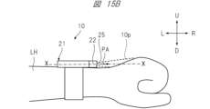
- FIG. 15A is a front view of the mobile information terminal 10 according to the first example.
- FIG. 15B is a side view of the portable information terminal 10 according to the first embodiment.
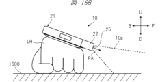
- FIG. 16A is a front view of the portable information terminal 10 according to the second example.
- FIG. 16B is a side view of the portable information terminal 10 according to the second example.
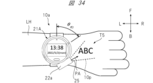
- the mobile information terminal 10 is worn on the outside of the user's left arm, and an image representing the letters "ABC" is projected.
- the direction of the projection aperture 25 of the projector section 22, that is, the projection aperture direction PA is set to the 3 o'clock direction, and the image T1 is projected onto the back of the left hand. There is.
- the projection opening direction PA is set to the 12 o'clock direction by rotating the attachment 21, and the image is projected onto the desk 1500 on which the user's left hand is placed. T2 is projected.
- the control unit 114 detects the rotation angle position and inclination angle of the attachment 21.
- the control unit 114 corrects the direction and spread of the projected light corresponding to the image representing the characters "ABC" in accordance with the detected rotation angle position and tilt angle of the attachment 21. This correction is performed so that the characters "ABC" represented by the projected image appear horizontal when viewed from the user.
- Such correction is mainly performed by controlling the image rotation of the displayed content, and has the effect of improving the visibility of the projected image.
- FIG. 17A is a front view of the mobile information terminal 10 according to the third example.
- FIG. 17B is a side view of the mobile information terminal 10 according to the third example.
- the mobile information terminal 10 is attached to the user's right arm RH, and an image representing the letters "ABC" is projected onto the back of the right hand.
- the portable information terminal 10 is attached to the left arm LH, but in the third embodiment shown in FIG. 17A, the portable information terminal 10 is attached to the right arm RH. Therefore, in the third embodiment, the attachment 21, that is, the bezel portion 213 itself is rotated by 180 degrees compared to the first embodiment shown in FIG. 15A. Therefore, it is necessary to display the image representing the characters "ABC" facing directly, as shown in FIG. 17A, so that the user can easily see the image.
- the control unit 114 corrects the projected image, that is, the projected light, based on the attachment rotation position so that the image is easier to see for the user.
- This correction is also mainly performed by controlling the image rotation of the displayed content, and has the effect of improving the visibility of the projected image.
- the portable information terminal 10 has an image shape control function.
- Image shape control is one type of projection control that is performed to improve the visibility of the projected image when projecting an image that is display content.
- the control unit 114 (FIG. 11) on the side of the terminal body 11 specifies the wearing state of the mobile information terminal, and controls the shape of the image suitable for the specified wearing state according to the specified wearing state.
- FIG. 18A is a front view of the mobile information terminal 10 according to the fourth example.
- FIG. 18B is a side view of the portable information terminal 10 according to the fourth example.
- FIG. 19 is a front view of the portable information terminal 10 according to the fifth embodiment.
- the mobile information terminal 10 is worn on the outside of the left arm, and an image representing a square is projected.
- the attachment 21 is rotated so that the direction of the central axis of the projection aperture 25 of the projector section 22, that is, the projection aperture direction PA is set to the 12 o'clock direction, and the user An image S1 is projected onto a desk top 1500 on which the left arm LH of a person is placed.
- the front side of the mobile information terminal 10 is naturally raised and tilted due to the structure and shape of the human skeleton, joints, or arms.
- the center line of the mobile information terminal 10, that is, the front-rear direction X is inclined with respect to the horizontal direction H at an inclination angle ⁇ r.
- the fourth example shows a state in which the image is not corrected based on the presence of the tilt angle when the image is projected onto the desk top 1500 on which the user's left arm LH is placed.
- the square represented by the image S1 is distorted into a trapezoidal shape due to the existence of the tilt angle ⁇ r from the horizontal direction H.
- control unit 114 detects the attachment rotation position and the inclination angle of the terminal body 11, and determines the direction and spread of the projected light corresponding to the image representing the square. Correct according to the detected rotation angle and tilt angle. This correction is performed so that the square represented by the projected image S2 appears to maintain its square shape when viewed from the user, as shown in FIG. Such correction is mainly performed by controlling the image shape of the displayed content, and since image distortion is reduced, it has the effect of improving the visibility of the projected image.
- the portable information terminal 10 has a function of controlling an image projection angle.
- Image projection angle control is one type of projection control that is performed to improve the visibility of the projected image when projecting an image that is display content.
- the control unit 114 (FIG. 11) on the side of the terminal main body 11 identifies the mounting state of the mobile information terminal, and controls the image projection angle suitable for the specified mounting state according to the specified mounting state.
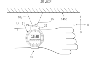
- FIG. 20A is a front view of the mobile information terminal 10 according to the sixth embodiment.
- FIG. 20B is a side view of the portable information terminal 10 according to the sixth embodiment.
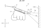
- FIG. 21 is a front view of the portable information terminal 10 according to the seventh embodiment.
- the mobile information terminal 10 is attached to the outside of the user's left arm and projects an image with the projection port 25 facing the front wall 1450. .
- the attachment 21 is rotated, the projector section 22 is directed toward 12 o'clock, and an image is projected onto a wall surface 1450 in front of the user.
- the front side of the arm will lift up due to the structure and shape of the human skeleton, joints, or arm. It often leans toward
- the front-rear direction X of the mobile information terminal 10 is inclined at an inclination angle ⁇ r with respect to the horizontal direction H, and the optical axis of the projected light 10p becomes an optical axis A1 parallel to the front-rear direction X.
- the sixth embodiment shows a state in which when an image is projected onto a wall surface 1450 in front of the user, image distortion based on the presence of the tilt angle ⁇ r and projection angle correction are not performed. .
- the projected image will be distorted into a trapezoidal shape due to the presence of the tilt angle ⁇ r from the horizontal direction H. Furthermore, the position of the projected image relative to the wall surface 1450 is also shifted downward.
- the control unit 114 detects the tilt angle of the mobile information terminal 10, that is, the attitude of the terminal main body 11. Then, as in the seventh embodiment shown in FIG. 21, the control unit 114 sets the projection angle of the image upward relative to the reference projection aperture direction PA so that the image is projected almost perpendicularly to the wall surface 1450.
- the projection angle of the image is controlled so that For example, as shown in FIG. 21, the projection angle is controlled so that the optical axis of the projected light 10p becomes an optical axis A2 that is approximately perpendicular to the wall surface 1450.
- Such correction of the optical axis of the projected light 10p is mainly performed by controlling the projection angle, and the projected position of the image is changed upward to reduce image distortion. This has the effect of improving image visibility.
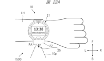
- FIG. 22A is a front view of the mobile information terminal 10 according to the eighth embodiment.
- FIG. 22B is a side view of the portable information terminal 10 according to the eighth embodiment.
- FIG. 23 is a front view of the portable information terminal 10 according to the ninth embodiment.
- the mobile information terminal 10 is worn on the outside of the user's left arm, and images that are display content are projected.
- the attachment 21 is rotated, the projection port direction PA is set to the 6 o'clock direction, and the image is projected onto the desk top 1500 on which the user's left arm LH is placed.
- the front side of the arm will lift up due to the structure and shape of the human skeleton, joints, or arm. It often leans toward
- the front-rear direction X of the mobile information terminal 10 is inclined with respect to the horizontal direction H at an inclination angle ⁇ r.
- the projection angle is not corrected based on the presence of the inclination angle ⁇ r. That is, the optical axis of the projected light 10p becomes an optical axis A3 parallel to the front-rear direction X on the display surface of the terminal main body 11.
- the projection light 10p representing the image is projected upward from the horizontal direction H due to the existence of the tilt angle ⁇ r from the horizontal direction H.
- the image is hardly projected onto the desktop 1500.
- the control unit 114 detects the inclination angle of the attachment 21, that is, the attitude of the terminal main body 11. Then, as in the ninth embodiment shown in FIG. 23, the control unit 114 controls the projection angle of the image to be downward relative to the reference projection aperture direction PA so that the image is projected onto the desk top 1500. , controls the image projection angle. For example, as shown in FIG. 23, the projection angle is controlled so that the optical axis of the projected light 10p becomes an optical axis A4 that intersects with the desk top 1500 near the left arm LH.
- Such correction of the optical axis of the projection light 10p is mainly performed by controlling the image projection angle, and the position where the image is projected is changed downward, so that the entire image is projected at a position that is easy for the user to see. At the same time, since image distortion is reduced, there is an effect of improving the visibility of the projected image.
- image rotation control and image shape control may be realized by an optical method that operates an optical system, or may be realized by an image processing method that operates image information, that is, image data.
- image processing method that operates image information, that is, image data.
- control section 114 has a function of detecting the rotation angle of the bezel section 213 and a function of detecting the tilt angle of the mobile information terminal 10 based on a predetermined mechanism or sensor.
- the control unit 114 can perform various display correction processes when projecting an image or video by the projector unit 22 based on the attachment rotation position and the terminal body posture obtained by such functions.
- Initial setting of projection control refers to setting appropriate projection control in advance according to the wearing state of mobile information terminal 10 so that images as display content are projected with good visibility.
- projection control suitable for projecting the image onto the back of the right hand is set in advance.
- rotation control is set so that the image is rotated 90 degrees clockwise so that the image is properly aligned vertically and horizontally.
- shape control is set so that the width of the image on the far side from the projection port 25 is narrower so that the trapezoidal distortion of the image is corrected.
- the projection angle control is set so that the projection angle is slightly downward from the direction of the display surface of the terminal main body 11 so that the image does not spread too much.
- the mobile information terminal 10 is worn on the outside of the user's left arm and the projection port 25 of the projector section 22 is set to face the 12 o'clock direction of the clock, the image that is the display content is It is assumed that it will be projected onto the wall in front. Therefore, in such a situation, projection control suitable for projecting the image onto the front wall is set in advance. For example, rotation control is set so that the image is not rotated so that the top, bottom, right, and left sides of the image are appropriate. Furthermore, due to the structure of the human body, it is natural for the outside of the arm to lean toward the wall in front of it, so there is a strong tendency for the image to be projected diagonally downward toward the wall. Therefore, the projection angle control is set so that the image is projected perpendicularly to the wall and the projection direction is slightly upward from the direction of the display surface of the terminal main body 11.
- image shape control may be set instead of projection angle control, or conversely, projection angle control may be set instead of image shape control.
- projection angle control and image shape control may be set simultaneously.
- the initial settings for projection control include whether the mobile information terminal 10 is attached to the left or right side or outside or inside of the arm, and the direction of the projection port 25. It may also be determined based on the attitude of the terminal main body 11, that is, the direction and degree of inclination.
- the control unit 114 identifies the wearing state of the mobile information terminal 10 when an image that is display content is projected, and performs projection appropriate for the specified wearing state. Perform initial control settings.
- the mounting state of the mobile information terminal 10 includes the mounting position of the mobile information terminal, the rotational position of the attachment, the attitude of the terminal body, and the like.
- the mounting position outside of the left arm, outside of the right arm, inside of the left arm, and inside of the right arm.
- 12 kinds of options are prepared for the position of the pin 23 of the bezel portion 213, which are positions in 1-hour increments from the 12 o'clock direction to the 11 o'clock direction of the watch.
- the terminal body posture is horizontal, front upward tilt (small), rear upward tilt (small), left upward tilt (small), right upward tilt (small), front upward tilt (large), rear upward tilt (large),
- Nine options are available: upper left tilt (large) and upper right tilt (large).
- a plurality of different setting information is stored in the storage 125.
- the plurality of different setting information are such that the wearing state of the mobile information terminal 10 is associated with setting information representing the initial setting of projection control suitable for the wearing state.
- the control unit 114 reads setting information corresponding to the specified wearing state from the storage 125, and performs initial settings for projection control based on the read setting information.
- FIG. 24 is a diagram showing an example of the setting information table.
- the setting information table is prepared in which, for example, setting information for projection control that is set for each mounting position of the mobile information terminal is compiled.
- a setting information table T01 is applied when the mobile information terminal 10 is worn on the outside of the left arm
- a setting information table T02 is applied when the mobile information terminal 10 is worn on the outside of the right arm
- a setting information table T02 is applied when the mobile information terminal 10 is worn on the outside of the left arm.
- a setting information table T03 is shown which is applied when the wear position is on the inside of the right arm
- a setting information table T04 is shown which is applied when the wearing position is on the inside of the right arm.
- these setting information tables T01 to T04 are stored in the storage 125.
- the setting information table may be one table.
- the setting information table may be stored in the memory 132 on the terminal main body 11 side, or may be stored in the memory 206 on the attachment 21 side.
- FIG. 25 is a diagram showing an example of detailed contents of the setting information table T01.
- FIG. 25 is shown as a representative example of the setting information tables T01 to T04 to facilitate understanding of the table.
- the items "attachment rotation position” and “terminal body posture” are provided as combination items, assuming that the attachment position is “outside” of the "left arm”.
- "setting information” corresponding to the combination of these items is associated. Note that here, each setting information is represented by a symbol J (j1, j2, j3, j4).
- j1 is a numerical value depending on whether the mounting position is on the left or right side of the arm
- j2 is a numerical value depending on whether the mounting position is outside or inside the arm
- j3 is a numerical value depending on the attachment rotation position
- j4 is a numerical value depending on the attitude of the terminal body.
- the "attachment rotational position” is also the rotational position of the attachment 21, and the rotational position of the projector unit 22, for example, the position of the pin 23 as its reference position, is the position of the time direction on a general clock. This is information indicating. Specifically, the "attachment rotational position" indicates which one is the 12 o'clock direction, the 1 o'clock direction, the 2 o'clock direction, . . . , the 11 o'clock direction.
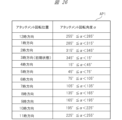
- FIG. 26 is a diagram representing a table AP1 showing an example of the correspondence between the attachment rotation position and the attachment rotation angle ⁇ .
- the bezel rotation angle ⁇ is set to 0° when the projector section is located in the 3 o'clock direction due to initialization when the bezel is attached. As shown in FIG. 26, for example, when 345° ⁇ 15°, the attachment rotation position is in the 3 o'clock direction. Further, for example, when 255° ⁇ 285°, the attachment rotation position is in the 12 o'clock direction.
- the "terminal body posture” is information indicating which direction and how much the display surface of the terminal body 11 is tilted.
- device body posture is horizontal, front-up tilt (small), rear-up tilt (small), right-up tilt (small), left-up tilt (small), front-up tilt (large), and rear-up tilt. (large), upper right tilt (large), or upper left tilt (large).
- front upward inclination (small) means that the front of the terminal main body 11 is inclined upward at a small angle.
- the upper right tilt (large) means that the right side of the terminal body 11 is tilted upward at a large angle.
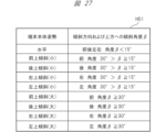
- FIG. 27 is a diagram representing a table HS1 showing an example of the correspondence between the terminal body posture, the tilt direction of the terminal body, and the upward tilt angle ⁇ .
- the inclination angle ⁇ is 0° when the display surface of the terminal main body 11 is horizontal. figure? As shown in FIG. 2, for example, when the upward tilt angle ⁇ 15° in the front, rear, left, and right directions, the terminal main body attitude is horizontal. Further, for example, when the inclination direction is forward and 30°> ⁇ 15°, the forward inclination becomes (small). Further, for example, when the inclination direction is rightward and ⁇ 30°, the upper right inclination is (large).
- FIG. 28 is a diagram showing an example of the contents of the setting information associated in the setting information table T01.
- a table T11 showing an example of the contents of setting information is shown.
- the setting information J (1, 1, 12, 1) indicates that the mounting position of the mobile information terminal 10 is on the outside of the left arm, the attachment rotation position is in the 12 o'clock direction, and the terminal body posture is This is the setting information when it is horizontal.
- the setting contents of the setting information include settings for rotation control, shape control, and projection angle control of display content.
- the setting contents of the setting information J (1, 1, 12, 1) are that for the rotation control of the display content, the rotation is 0°, and for the shape control of the display content, the setting is linear or There is no shape correction, and the projection angle control is set to 0°.
- the settings of the setting information J (1, 1, 6, 3) are as follows: For the rotation control of the display content, the rotation is 180 degrees clockwise (CW), and for the shape control of the display content, Correction is performed to narrow the far width of the image, and the projection angle is set to be 30 degrees downward.
- the control unit 114 refers to the setting information table described above, reads setting information according to the detected wearing state, and performs initial settings for projection control based on the setting information.
- the wearing state and setting information are explained in a simple manner for ease of understanding, but in reality, the wearing state and setting information may be defined by more complex and detailed items. Conceivable. According to such a configuration that performs initial settings for projection control, since projection control suitable for the wearing state of the mobile information terminal is performed in advance, there is no need for subsequent adjustment of projection control, or subsequent projection control by the user. The visibility of displayed content can be improved just by making small adjustments.
- the initial setting of projection control may be performed based on information input by the user.
- the user may input the wearing state of the mobile information terminal 10, and the control unit 114 may initialize the projection control suitable for the input wearing state.
- the user may directly perform initial settings, current settings, fine adjustments, etc. of the projection control.
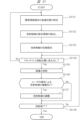
- FIG. 29 is a flow diagram illustrating an example of a process for automatically determining whether the arm on which the mobile information terminal 10 is attached is left or right.
- the flowchart shown in FIG. 29 represents an example of a processing procedure by the control unit 114 for determining whether the mobile information terminal 10 is worn on the left or right arm of the user.
- This discrimination processing algorithm is based on the premise that the user often has his or her arms hanging downward (in the direction of gravity) while walking.
- step S2901 it is determined whether the person is walking. Specifically, the control unit 114 determines whether the user wearing the mobile information terminal 10 is walking based on the output history of at least one of the acceleration sensor 133 and the gyro sensor 136 over a certain period of time. .
- the output of the acceleration sensor 133 or the gyro sensor 136 repeats changes with an amount of change greater than a certain level. Therefore, it can be determined whether the person is walking based on whether or not such characteristics are recognized.
- control unit 114 advances the step to be executed to S2902. On the other hand, if it is determined that the user is not walking (S2901: No), the control unit 114 moves the step to be executed to S2906.
- step S2902 it is determined whether the direction of gravity of the mobile information terminal 10 is in the 3 o'clock direction. Specifically, the control unit 114 determines whether the direction of gravity of the mobile information terminal 10 is near the 3 o'clock direction of the wristwatch based on the output of the acceleration sensor 133. In this determination, if it is determined that the direction of gravity is near the 3 o'clock direction (S2902: Yes), the control unit 114 advances the step to be executed to S2904. On the other hand, if it is determined that the direction of gravity is not near the 3 o'clock direction (S2902: No), the control unit 114 moves the step to be executed to S2903.
- step S2903 it is determined whether the direction of gravity of the mobile information terminal 10 is the 9 o'clock direction. Specifically, the control unit 114 determines, based on the output of the acceleration sensor 133, whether the direction of gravity of the mobile information terminal 10 is near the 9 o'clock direction of the wristwatch. In this determination, if it is determined that the gravity direction is near the 9 o'clock direction (S2903: Yes), the control unit 114 advances the step to be executed to S2905. On the other hand, if it is determined that the gravity direction is not near the 3 o'clock direction (S2903: No), the control unit 114 moves the step to be executed to S2906.
- step S2904 as a process executed when it is determined that the user is walking and the gravity direction of the acceleration sensor output is in the 3 o'clock direction, a process of counting up the variable LW corresponding to the determination result. will be held. Specifically, the control unit 114 sets a value obtained by adding 1 to the value of the variable LW as a new value of the variable LW. When step S2904 is executed, the control unit 114 moves the step to be executed to S2906.
- step S2905 as a process to be executed when it is determined that the user is walking and the gravity direction of the acceleration sensor output is in the 9 o'clock direction, a process of counting up the variable RW corresponding to the determination result is performed. It will be done. Specifically, the control unit 114 sets a value obtained by adding 1 to the value of the variable RW as the new value of the variable RW. When step S2905 is executed, the control unit 114 moves the step to be executed to S2906.
- variables LW and RW are variables used in the program of the control unit 114, and are initialized when the mobile information terminal 10 is turned on or when a system reset process (not shown) is performed by the user. and the value shall be zero.
- step S2906 it is determined whether or not there is a significant difference between the values of variable LW and variable RW. Specifically, the control unit 114 determines whether either the value of the variable LW or the value of the variable RW exceeds the threshold value TH1, and the ratio of the value of the variable LW to the total count number and the ratio of the value of the variable RW. It is determined whether there is a situation in which the difference between the two values exceeds a threshold value TH2. If it is determined that such a situation exists, the control unit 114 advances the step to be executed to S2907. On the other hand, if it is determined that such a situation does not exist, the control unit 114 returns the step to be executed to S2901.
- step S2907 the value of variable LW and the value of variable RW are compared. Specifically, the control unit 114 determines which of the following relationships holds: (1) value of variable LW>value of variable RW, or (2) value of variable LW ⁇ value of variable RW.
- the control unit 114 determines that the user is wearing the mobile information terminal 10 on his left arm (S2908), and ends the determination process.
- the control unit 114 determines that the user is wearing the mobile information terminal 10 on his right arm (S2909), and ends the determination process.
- the physical information measurement sensor 16 irradiates the object with a green light source and outputs a signal according to the amount of light reflected from the object.
- the thickness or number of blood vessels passing near the surface of the arm that is, the blood flow rate, differs between the outside of the arm (on the back of the hand) and the inside of the arm (on the opposite side of the hand).
- the amount of reflected green light varies depending on the blood flow rate. That is, the physical information measurement sensor 16 outputs different signals depending on whether the outside of the arm is irradiated with the green light or the inside of the arm is irradiated with the green light. By utilizing such characteristics, it is possible to determine whether the portable information terminal 10 is worn on the outside or inside of the arm based on the output of the physical information measurement sensor 16.
- FIG. 30 is a flow diagram illustrating an example of a process for determining whether the arm on which the mobile information terminal 10 is attached is inside or outside.
- step S3001 light is emitted to the arm.
- the control unit 114 controls the physical information measurement sensor 16, and the physical information measurement sensor 16 emits green light to the user's arm.
- step S3002 the light reflectance of the arm is measured.
- the control unit 114 receives a signal output from the physical information measurement sensor 16, detects the amount of green light emitted from the arm and reflected from the arm, and detects the amount of green light emitted from the arm based on the amount of light reflected from the arm. Measure light reflectance.
- step S3003 it is determined whether the measured light reflectance exceeds a threshold value. Specifically, the control unit 114 determines whether the measured light reflectance of the arm exceeds a predetermined threshold th. In this determination, if it is determined that the light reflectance exceeds the threshold th (S2003: Yes), the control unit 114 advances the processing step to step 3004. On the other hand, if it is determined that the light reflectance does not exceed the threshold th (S3003: No), the control unit 114 advances the processing step to step S3005.
- step S3004 the control unit 114 determines that the mobile information terminal 10 is worn on the outside of the user's arm. On the other hand, in step S3005, the control unit 114 determines that the mobile information terminal 10 is worn on the inside of the user's arm.
- FIG. 31 is a flow diagram illustrating an example of a process related to display content projection on the mobile information terminal 10.
- step S3101 the mounting state of the mobile information terminal 10 is identified.
- the control unit 114 specifies the terminal mounting position, the attachment rotation position, and the terminal body posture as items regarding the mounting state of the mobile information terminal 10. For example, the method described above is used to specify each item of the wearing state.
- step S3102 projection control setting information is read.
- the control unit 114 refers to the setting information table stored in the storage 125 and reads out from the storage 125 the projection control setting information associated with the specified combination of wearing state items. That is, the control unit 114 reads out projection control setting information suitable for the specified wearing state according to the specified wearing state.
- step S3103 initial settings for projection control are performed. Specifically, the control unit 114 performs initial settings for image rotation control, image shape control, and image projection angle control based on the read setting information.
- step S3104 it is determined whether there has been a change in the attachment rotational position. Specifically, the control unit 114 determines whether there has been a change in the attachment rotational position detected almost in real time. In this determination, if it is determined that there has been a change (S3104: No), the control unit 114 returns the processing step to step S3101. On the other hand, in this determination, if it is determined that there is no change (S3104: Yes), the control unit 114 advances the processing step to step S3105.
- step S3105 image projection is performed. Specifically, the control unit 114 corrects the image by performing set image rotation control and image shape control on the image that is the display content. Then, the control unit 114 transmits image information representing the corrected image, that is, image data, and setting information for projection angle control to the projector unit 22. The control unit 204 on the projector unit 22 side controls the projection angle based on the received projection angle control setting information. Further, the control unit 204 projects an image represented by the received image data by controlling each unit related to image projection.
- step S3106 a process is performed to determine whether or not projection control, display content rotation control, shape control, and projection angle control are adjusted by user operations.
- the control unit 114 executes processing to detect a user's operation, and when a user's operation is detected, adjusts projection control and rotates display content based on information input by the user. Determine if there are any adjustments to control, shape control, and projection angle control. In this determination, if it is determined that there is an adjustment (S1506: Yes), processing is performed to advance the processing step to step S1507. On the other hand, if it is determined that there is no adjustment (S1506: No), the process proceeds to step S1508.
- step S1507 a process of adjusting projection control is performed. Specifically, the control unit 114 adjusts the projection control based on projection control adjustment information input by the user's operation.
- step S1508 it is determined whether or not to end the projection. Specifically, the control unit 114 checks whether a reason for terminating the projection has occurred. Possible reasons for terminating the projection include, for example, an error has occurred in the process, or an instruction to terminate the projection has been input by a user operation. If a reason for terminating the projection occurs, it is determined that the projection has ended, and if a reason for terminating the projection does not occur, it is determined that the projection has not ended. In this determination, if it is determined that the projection has ended (S3108: Yes), the projection is ended. On the other hand, if it is determined that the projection has not ended (S3108: No), the control unit 114 returns the processing step to step S1504.
- a reason for terminating the projection include, for example, an error has occurred in the process, or an instruction to terminate the projection has been input by a user operation. If a reason for terminating the projection occurs, it is determined that the projection has ended, and if a reason for terminating the projection does not occur,
- the mobile information terminal according to the first embodiment since the mobile information terminal according to the first embodiment has the function of image rotation control, when projecting an image as display content, the projected image is rotated by the mobile information terminal. It can be rotated to a rotation angle suitable for the wearing condition. For example, even if the direction in which the image is projected changes, the horizontality of the image can be maintained. As a result, visibility of displayed content can be improved. Particularly when sharing display content with a person other than the user, it becomes possible to project the display content with good visibility even for the person other than the user.
- the mobile information terminal since it has an image shape control function, when projecting an image as display content, the image is shaped into a shape suitable for the state in which the mobile information terminal is worn. It can be transformed into. For example, if the surface of the object onto which the image is projected is tilted with respect to the projection direction, the image will have trapezoidal distortion, but such trapezoidal distortion can be corrected. As a result, visibility of displayed content can be improved. Particularly when sharing display content with a person other than the user, it becomes possible to project the display content with good visibility even for the person other than the user.
- the mobile information terminal since it has a projection angle control function, when projecting an image that is display content, the projection angle is adjusted to suit the wearing state of the mobile information terminal.
- the angle can be adjusted. For example, if the surface of the object onto which the image is projected is tilted with respect to the projection direction, the image will have trapezoidal distortion, but such trapezoidal distortion can be corrected. As a result, visibility of displayed content can be improved. In particular, when display content is shared with a person other than the user, the visibility of the display content is improved even for the person other than the user.
- the mobile information terminal based on the identified wearing state of the mobile information terminal, initial setting of projection control suitable for the projection form of display content assumed from the wearing state is performed. Therefore, the visibility of the projected display content can be further improved. In particular, when display content is shared with a person other than the user, the visibility of the display content is improved even for the person other than the user.
- the mounting state of the mobile information terminal that is, the mounting position, the attachment rotation position, and the terminal main body posture can be automatically detected using the sensor, and the projection It is possible to automatically initialize control settings, which is convenient for the user.
- the attachment is removable, and attachments that have functions other than the projector function, such as those that have a projector function and those that have a camera function, can be attached to the terminal body. It can be installed. According to the portable information terminal having such a configuration, the user can use an attachment suitable for the purpose, which is convenient for the user.
- an attachment having a projector function can be rotatably attached to the terminal body.
- the mobile information terminal according to the first modification example includes an attachment that is provided with a projector part whose projection opening direction is different from the radial direction of the circumference of the bezel part, as an attachment option that can be attached to the terminal body.
- the direction of the projection opening is, for example, the tangential direction of the circumference of the bezel portion.
- FIG. 32A is a front view of the mobile information terminal 10a according to the first modification of the first embodiment.
- FIG. 32B is a side view of the mobile information terminal 10a.
- the projection port of the projector section 22a in the attachment 21A that is, the opening that is the exit of the projected light 10p is formed at one end in the longitudinal direction of the projector section 22a. has been done. That is, in the portable information terminal 10a of this embodiment, the projection opening direction PA of the projector section 22a is set to be the tangential direction of the circumference of the bezel section 213.
- FIG. 33 is a diagram showing an embodiment of the mobile information terminal 10a.
- the mobile information terminal 10a is attached to the outside of the user's left arm LH, and the projection light 10p corresponding to the image T4 representing the characters "ABC" which is the display content is transmitted from the projector unit 22 to the back of the user's hand. is projected on.
- the bezel portion 213 is rotated by a rotation angle ⁇ d1 in order to project an image onto the back of the user's left arm LH.
- the control unit 114 does not perform rotation control of the projected image. In other words, an image without rotation correction is projected onto the back of the hand. In this case, the characters "ABC" appear to be tilted diagonally to the user.
- FIG. 34 is a diagram showing a modification to the embodiment of the mobile information terminal 10a shown in FIG. 33.
- the control unit 114 detects the rotation angle ⁇ d1 of the attachment 21A, and changes the shape of the image based on the rotation angle ⁇ d1 so that the letters "ABC" are displayed along the longitudinal direction of the arm. to correct. Therefore, according to this configuration, it appears to the user that the characters "ABC" are displayed in the horizontal direction, that is, along the longitudinal direction of the arm, and the visibility of the projected image is improved.
- FIG. 35 is a diagram showing an example of a setting information table.
- the setting information table is prepared in which, for example, setting information of projection control to be set is compiled for each mounting position of the information terminal.
- a setting information table T11 is applied when the mobile information terminal 10a is worn on the outside of the left arm
- a setting information table T12 is applied when the mobile information terminal 10a is worn on the outside of the right arm
- a setting information table T12 is applied when the mobile information terminal 10a is worn on the outside of the left arm.
- a setting information table T13 is shown which is applied when the item is worn
- a setting information table T14 is shown which is applied when the wearing position is on the inside of the right arm.
- these setting information tables T11 to T14 are stored in the storage 125.
- FIG. 36 is a diagram showing an example of detailed contents of the setting information table T11.
- FIG. 36 is shown as a representative example of the setting information tables T11 to T14 to facilitate understanding of the table.
- the setting information table T11 as combination items, in addition to "attachment rotation position" and “terminal body posture", assuming that the attachment position is “outside” of "left arm", An item of "projection port direction” is provided, and "setting information" corresponding to the combination of these items is associated.
- the "projection aperture direction” is information representing the direction of the optical axis or principal axis of the projection light 10p emitted from the projection aperture 25.
- the “projection aperture direction” for example, “radial direction” and “tangential direction” of the circumference of the bezel portion 213 are prepared.
- the portable information terminal according to the second modification has an attachment that allows the projector section to rotate with respect to the bezel section, as an attachment option that can be attached to the terminal main body. That is, the portable information terminal according to the second modification is configured to be able to change the image projection direction by changing the rotational position of the projector unit.
- FIG. 37A is a front view of the mobile information terminal 10b according to the second modification of the first embodiment. Further, FIG. 37B is a side view of the mobile information terminal 10b according to the second modification of the first embodiment.
- the mobile information terminal 10b includes an attachment 21B in which the projector section 22a is configured to be rotatable with respect to the bezel section 213.
- the attachment 21B includes a rotation mechanism 229 that allows the projector section 22a to rotate relative to the bezel section 213 about a direction parallel to the display surface direction of the terminal main body 11.
- the projection aperture direction PA of the projector section 22a is the tangential direction of the circumference of the bezel section 213, as in the first modification.
- the mounting state of the mobile information terminal includes the item "rotation angle of projector unit”.
- “Projector unit rotation angle” is information representing the rotation angle of the projector unit 22a with respect to the bezel unit 213, that is, information indicating the rotational state of the projector unit 22a.
- the control unit 114 performs initial settings for projection control that are considered suitable for the mounting state of the mobile information terminal, depending on a combination of a plurality of items including the "rotation angle of the projector unit.” That is, the setting information table is a table that includes "projector unit rotation angle", which is the rotational state of the projector unit 22a, as one of the items associated with the setting information.
- Embodiment 2 A portable information terminal according to Embodiment 2 will be described.
- the mobile information terminal according to the first embodiment has a rotating bezel type attachment
- the mobile information terminal according to the second embodiment has a terminal connection type attachment. . That is, the projection direction of the image can be changed depending on the connection position of the attachment to the terminal body.
- FIG. 38 is a diagram illustrating a configuration example of a mobile information terminal 10c according to the second embodiment.
- the portable information terminal 10c has a terminal main body 11c that is approximately rectangular in shape.
- the terminal main body 11c has a plurality of different connection terminals, and these connection terminals are respectively provided in four directions of the top, bottom, left and right of the terminal main body 11c.
- the attachment 21C which is integrated with the projector section, is configured to be able to be inserted into and removed from each of the connection terminals provided in the four directions of the top, bottom, right and left of the terminal body 11c.
- the direction in which the image or video is projected from the attachment 21C is the same as that shown in FIG. That is, in a state where the attachment 21C is attached to the terminal body 11c, an image or video is projected on the side opposite to the side of the terminal body 11c.
- the direction of the projection port is determined by the mounting position of the attachment 21C on the terminal main body 11c. Therefore, the pattern detection sensors 12c and 12d for detecting the rotation angle of the attachment 21C necessary for correcting the projected image, the detection pattern as a rotary encoder on the bezel portion 213 side, etc. are no longer necessary, simplifying the structure of the mobile information terminal. can be converted into
- the mobile information terminal according to the first modification example includes an attachment that is provided with a projector section whose projection opening direction is different from the direction of radiation from the center of the terminal body, as an attachment option that can be attached to the terminal body.
- the projection opening direction is, for example, a direction perpendicular to the radial direction from the center of the terminal body.
- FIG. 39 is a diagram showing a mobile information terminal 10d that is a first modification of the second embodiment.
- the mobile information terminal 10d has an attachment 21D integrated with the projector section.
- the projection opening direction PA of the projector unit in the attachment 21D is a direction perpendicular to the radial direction from the center of the terminal main body 11, and specifically, the direction PA of the projector section is the longitudinal direction of the attachment 21D. That is, the projection port of the projector section of the attachment 21D is formed at one end in the longitudinal direction of the attachment 21D.
- the projection port direction PA is determined by the mounting position of the attachment 21D with respect to the terminal main body 11c. Therefore, the pattern detection sensors 12c and 12d for detecting the rotational position of the attachment required for image correction, the detection pattern as a rotary encoder on the attachment 21D side, etc. are not required, and the structure of the portable information terminal can be simplified.
- the optical projection angle with respect to the projector unit is assumed to be unchanged.
- the attachment or the projector section may be configured such that all or part of the optical system of the projector section is mechanically variable, and the control section may control the angle thereof.
- a gyro sensor is mounted on the terminal body of the mobile information terminal in Embodiments 1 to 3. Therefore, for example, when a user is wearing a mobile information terminal on their arm and projects an image onto a wall in front of them, vibrations in the user's arm and camera shake can be detected, and image processing can be used to correct the camera shake. be able to.
- the electrical connection between the power source and the signal between the terminal main body of the portable information terminal and the attachment is realized using a slip ring and a terminal.
- the electrical connection of signals may be realized by close proximity wireless connection, or the electrical connection of the power source may be realized by wireless power supply, and the electrical connection of signals may be realized by close proximity wireless connection. It may be realized by wireless connection. According to such a configuration, since the number of sliding parts of the electrical connection part can be reduced, it is possible to reduce mechanical wear and tear, and it is easy to create a waterproof structure. Furthermore, it is also possible to reduce manufacturing costs.
- Embodiments 1 to 3 an example was shown in which a mobile communication interface is mounted on the main body of a portable information terminal.
- the mobile communication interface may be mounted not on the main body but on the detachable attachment side.
- attachments having different functions may be prepared, for example, attachments having a communication function such as LTE, and attachments having an imaging function. In this way, the user can freely expand the functions of the mobile information terminal by later acquiring an attachment having the necessary functions as needed. In other words, the product configuration of the mobile information terminal can be made functionally expandable.
- projection control that is, image rotation control, image shape control, and projection angle control
- a control unit on the terminal main body side acquires information necessary for the above projection control using a sensor, etc., transmits that information to the attachment, and the control unit on the attachment side performs the above projection control based on the received information. You can do it like this.
- the control unit on the terminal body side sends information about the image to be projected to the attachment, and the control unit on the attachment side acquires the information necessary for the projection control using a sensor mounted on itself, and then transmits the information on the image to be projected. Control may also be performed.
- each of the embodiments described above may be partially or entirely configured by hardware, or may be configured to be realized by executing a program on a processor.
- control lines and information lines are shown to be necessary for explanation purposes, and not all control lines and information lines are necessarily shown in the product. In reality, almost all components may be considered to be interconnected.
Landscapes
- Engineering & Computer Science (AREA)
- Physics & Mathematics (AREA)
- Computer Hardware Design (AREA)
- General Physics & Mathematics (AREA)
- Theoretical Computer Science (AREA)
- Telephone Set Structure (AREA)
Abstract
画像投射機能を付加することが可能な携帯情報端末において、投射される画像の視認性を向上させる技術を提供する。携帯情報端末は、端末本体と、端末本体に装着され、端末本体と通信可能に接続されるアタッチメントとを備える。アタッチメントは、端末本体から得られた画像情報に基づいて画像を投射するプロジェクタ部を有し、プロジェクタ部の投射口方向が端末本体に対して可変となるように構成されている。端末本体またはアタッチメントは、アタッチメントの端末本体に対する位置を含む携帯情報端末の状態を特定する。端末本体またはアタッチメントは、特定された状態に基づいて画像の投射制御を行う。投射制御は、例えば、画像回転制御、画像形状制御、または、投射角度制御を含む。
Description
本発明は、携帯情報端末、端末本体、およびアタッチメントに関する。
近年、スマートウォッチと呼ばれる腕に装着するタイプの携帯情報端末が知られている。スマートウォッチには、タッチスクリーン、種々の制御装置、センサ等が搭載されている。ユーザは、例えば、タッチスクリーンに表示された文字あるいはアイコンに触れて操作することにより、センサで計測した心拍数などの生体情報を表示させたり、電子メールの受信状況を表示させたりするなど、種々の機能を利用することができる。
上記した腕に装着するタイプの携帯情報端末の一つとして、ユーザが情報を視認しやすいように、本体の表示画面とは別に小型の表示部を搭載し、その小型の表示部に情報を表示させる機能を有するものが知られている。例えば、特許文献1には、下記のような電子機器が記載されている。
電子機器が有する筐体は、筐体の正面に位置する第1の部分、筐体の側面に位置する第2の部分、第1のバンド取付け部、及び第2のバンド取付け部を有する。第2の部分は、画像を表示する機能を有する。第1のバンド取付け部は、筐体の正面側から見て上側に位置する側面に位置する。第2の部分と、第2のバンド取付け部は、筐体の正面側から見て下側に位置する側面に位置する。第1の部分は、画像を表示する機能を有する、または時針、分針、及び秒針のうち、少なくとも一を有する。このような構成により、使用者は、表示される情報を読み取りやすくなる。
特許文献1に記載の電子機器は、筐体の側面に小さな表示部が搭載された構成を有している。そのため、例えば、電子機器を身に着けたユーザが、表示される情報をユーザ以外の者と共有したいと考える場合などにおいて、ユーザ以外の者にとっての情報の視認性の良さについては考慮されていない。また例えば、電子機器の狭い側面に第2の表示画面を加えただけでは、ユーザ自身が多くの情報を視認しようとする場合にも十分使い勝手が良いとは言い難い。すなわち、表示される情報の視認性について向上の余地がある。
上記事情により、携帯情報端末において、表示される情報の視認性をより向上させる技術の提供が望まれている。
本発明の代表的な実施の形態の一つは、腕に装着される携帯情報端末であって、端末本体と、前記端末本体に装着され、前記端末本体と通信可能に接続されるアタッチメントとを備え、前記アタッチメントは、前記端末本体から得られた画像情報に基づいて画像を投射するプロジェクタ部を有し、当該プロジェクタ部の投射口方向が前記端末本体に対して可変となるように構成されており、前記端末本体または前記アタッチメントは、前記アタッチメントの前記端末本体に対する位置を含む前記携帯情報端末の状態を特定し、前記端末本体または前記アタッチメントは、前記特定された状態に基づいて前記画像の投射制御を行う、携帯情報端末である。
本発明の代表的な実施の形態の一つは、腕に装着される携帯情報端末を構成する端末本体であって、画像を投射するプロジェクタ部を有し当該プロジェクタ部の投射口方向が前記本体に対して可変となるように構成されたアタッチメントを装着する機構と、前記アタッチメントと情報を授受する通信部と、前記通信部を介して前記アタッチメントに送信する画像情報を生成する生成手段と、前記アタッチメントからの投射口方向を表す情報を取得する取得手段とを備え、前記取得手段が取得した情報に基づいて前記画像情報を編集する、端末本体である。
本発明の代表的な実施の形態の一つは、腕に装着される携帯情報端末を構成するアタッチメントであって、前記携帯情報端末の本体に装着され、前記本体と通信可能に接続され、前記本体から得られた画像情報に基づいて画像を投射するプロジェクタ部を有し、当該プロジェクタ部の投射口方向が前記本体に対して可変となるように構成されており、前記本体または前記アタッチメントは、前記アタッチメントの前記本体に対する位置を含む前記携帯情報端末の状態を特定し、前記本体または前記アタッチメントは、前記特定された状態に基づいて前記画像の投射制御を行う、アタッチメントである。
本発明の代表的な実施の形態によれば、携帯情報端末において、表示される情報の視認性をより向上させる技術を提供することができる。
以下、本発明の実施の形態について図面を用いて説明する。なお、各実施の形態および図面において、同一もしくは同等の構成要素には同一の番号や符号を付し、特別な場合を除いて説明の繰り返しを省略するものとする。
(実施の形態1)
実施の形態1に係る携帯情報端末について説明する。実施の形態1に係る携帯情報端末は、表示コンテンツである画像あるいは動画の映像など(以下、単に画像ともいう)を投射する機能を有するものである。また、実施の形態1に係る携帯情報端末は、一例として、ユーザの腕に装着される、いわゆる腕時計型のものである。まず、実施の形態1に係る携帯情報端末の構成について説明する。
実施の形態1に係る携帯情報端末について説明する。実施の形態1に係る携帯情報端末は、表示コンテンツである画像あるいは動画の映像など(以下、単に画像ともいう)を投射する機能を有するものである。また、実施の形態1に係る携帯情報端末は、一例として、ユーザの腕に装着される、いわゆる腕時計型のものである。まず、実施の形態1に係る携帯情報端末の構成について説明する。
〈携帯情報端末の構成〉
図1Aは、実施の形態1に係る携帯情報端末10の正面図である。また、図1Bは、実施の形態1に係る携帯情報端末10の側面図である。なお、これより説明する各実施の形態においては、図1A,図1Bに示すように、携帯情報端末の表示面を正面から見た場合の、上向き方向を前方向F、下向き方向を後方向B、右向き方向を右方向R、左向き方向を左方向L、手前向き方向を上方向U、先向き方向を下方向Dとする。
図1Aは、実施の形態1に係る携帯情報端末10の正面図である。また、図1Bは、実施の形態1に係る携帯情報端末10の側面図である。なお、これより説明する各実施の形態においては、図1A,図1Bに示すように、携帯情報端末の表示面を正面から見た場合の、上向き方向を前方向F、下向き方向を後方向B、右向き方向を右方向R、左向き方向を左方向L、手前向き方向を上方向U、先向き方向を下方向Dとする。
図1A,図1Bに示すように、携帯情報端末10は、主に、端末本体11と、アタッチメント21とにより構成される。
端末本体11は、円周状の周縁部を有している。また、端末本体11は、構成要素として、筐体12、タッチスクリーン部13、マーク部14、ベルト17、およびホームボタン191を有している。
筐体12は、端末本体11のいわゆるハウジングに相当し、概ね、柱軸長が短い円柱形状、あるいは、厚みのある円板形状を有している。タッチスクリーン部13は、筐体12の表面に設けられており、例えば、矩形形状もしくは円板形状を有している。タッチスクリーン部13は、表示部と入力部とが一体化された構造を有する。表示部は、時刻、生体情報、その他の情報を表示するものであり、液晶パネル、有機ELなどの表示素子等で構成される。入力部は、ユーザによるタッチ操作を受け付けるものであり、静電容量方式のタッチセンサ等で構成される。
マーク部14は、筐体12における特定の方向および位置に配置されており、目印として機能する。本実施例では、マーク部14は、三角形のマークであり、一般的な腕時計の12時方向に位置している。ベルト17は、筐体12と接続されており、携帯情報端末10がユーザの腕に装着されるようにその腕に巻くためのものである。
ホームボタン191は、筐体12のタッチスクリーン部13の表示面側に、タッチスクリーン部13とは別に設けられている物理ボタンである。ホームボタン191は、例えば、表示される情報をメインメニューの画面に戻すために用いられる。
アタッチメント21は、筐体12の側面を形成する円周状の周縁部に対して着脱可能に構成されている。また、アタッチメント21は、筐体12の周縁部に装着された場合に、筐体12に対して回転可能に構成されている。また、アタッチメント21は、端末本体11と通信可能に構成されている。
アタッチメント21は、主に、ベゼル部213と、プロジェクタ部22とにより構成される。
ベゼル部213は、筐体12の周縁部に装着可能に構成されている。また、ベゼル部213は、筐体12の周縁部に装着された場合に、タッチスクリーン部13の表示画面を囲む環状の枠部となり、筐体12に対して回転可能に構成されている。プロジェクタ部22は、ベゼル部213に、ベゼル部213と一体的に構成されるように設けられている。
プロジェクタ部22は、表示コンテンツを表す画像を、手の甲、壁、机などの対象物に投射する機能を有している。プロジェクタ部22には投射口25が形成されており、投射口25の開口の中心軸方向である投射口方向PAに向かって、投射口25から投射光10pを広げるように投射する。なお、アタッチメント21の構成の詳細については後述する。
図2は、図1に示した携帯情報端末10のA-A線の断面図である。図2は、アタッチメント21が筐体12に装着されている状態を示している。また、図2において、斜線部はアタッチメント21の断面を表している。
携帯情報端末10は、身体情報計測センサ16を有している。身体情報計測センサ16は、ユーザが携帯情報端末10を腕に装着した場合に、肌に触れるように配置されている。身体情報計測センサ16は、ユーザの脈拍数、心電図、血流量などを計測する機能を有しており、計測結果に応じた信号を出力する。
筐体12は、表示面側凸部12aと、センサ側凸部12bとを有している。表示面側凸部12aは、タッチスクリーン部13の表示面側に円周方向に沿って形成されており、テーパー形状を有する凸部である。センサ側凸部12bは、筐体12の身体情報計測センサ16が配置されている側に円周方向に沿って形成されており、半径方向に幅dを有する凸部である。このように、筐体12の円周形状に倣うようにベゼル部213の内周側を形成することで、携帯情報端末10は、筐体12からベゼル部213が外れないように構成されている。
携帯情報端末10は、筐体12の中に、制御基板15を有している。制御基板15は、携帯情報端末10のシステムを制御したり、タッチスクリーン部13の表示を制御したり、ベゼル部213のプロジェクタ部22から投射する画像を制御したりするものである。また、携帯情報端末10は、ベゼル部213に設けられたプロジェクタ部22の筐体内部に、内部空間22iを有している。内部空間22iには、後に詳述するプロジェクタ部22の制御基板27、あるいは図示しない投射光学系などが収められている。
図3は、端末本体11の表示面側から見た正面図である。すなわち、図3は、携帯情報端末10のベゼル部213が外された状態を示している。図3に示すように、端末本体11の筐体12には、パターン検出センサ12c,12dが設けられている。パターン検出センサ12c,12dは、光を照射し、照射した光の反射面のパターンに応じた反射光量を検出する。これらのパターン検出センサ12c,12dの動作の詳細については、後述する。
図4は、図3に示す端末本体11のB-B線の断面図である。図4に示すように、筐体12には円周側面に沿って複数の溝が形成されており、これらの溝にはスリップリング18a~18dが設けられている。ベゼル部213は、スリップリング18a~18dに対して回転可能に勘合し、ベゼル部213とスリップリング18a~18dとは、電気的に接続可能に構成されている。各スリップリング18a~18dは、それぞれの間で電気的に絶縁されている。
ここでは、一例として、スリップリング18a、18dは、端末本体11に含まれる電源から電力をベゼル部213側に供給する端子として割り振られており、スリップリング18b、18cは、差動の2値化信号でベゼル部213と信号を送受信する端子として割り振られている。
図4に示すように、センサ側凸部12bには、筐体側ベゼル裏面接触面12eが形成されている。パターン検出センサ12c、12dは、筐体側ベゼル裏面接触面12e上に配置される。筐体側ベゼル裏面接触面12eは、ベゼル部213の半径方向に幅dを有している。
ここで、アタッチメント21の構成について、図面を参照しながら詳しく説明する。
図5は、アタッチメント21の正面図である。図5に示すように、ベゼル部213は、第1の半円状パーツ211と、第2の半円状パーツ212と、ピン23と、留め具24とを有している。第1の半円状パーツ211および第2の半円状パーツ212は、それぞれ、概ね、半円形状を有しており、円周方向の一端に貫通孔が形成されている。ピン23は、第1の半円状パーツ211の貫通孔と第2の半円状パーツ212の貫通孔とが重ねられた状態で、これら貫通孔に挿入され、第1の半円状パーツ211と第2の半円状パーツ212とを、ピン23を支点に開閉可能に接続するものである。留め具24は、第1の半円状パーツ211と第2の半円状パーツ212とが閉じた状態で、第1の半円状パーツ211と第2の半円状パーツ212とを接続して固定するものである。
プロジェクタ部22は、第2の半円状パーツ212の外周の中央付近に、端末本体11と干渉しないように設けられており、第1の半円状パーツ211と一体的に構成されている。プロジェクタ部22は、文字、図形、像などを表す画像あるいは動画などの表示コンテンツが物体に投射されるように投射光を投射するよう構成されている。投射口25は、プロジェクタ部22の側面に設けられており、投射光10pが投射される光学的な開口である。そのため、ベゼル部213と一体化されたプロジェクタ部22は、ベゼル部213と共に回転が可能であり、プロジェクタ部22からの投射光10pの拡がり方向は、360度自在に変化させることが可能である。
第1の半円状パーツ211および第2の半円状パーツ212が、筐体12の側面を囲むようにして閉じた状態で、留め具24により接続されることにより、ベゼル部213は、端末本体11に装着される。このような構成により、アタッチメント21は、端末本体11に対して着脱が可能である。
図6は、図5に示すアタッチメント21のC-C線の断面図である。第1の半円状パーツ211および第2の半円状パーツ212のうち、プロジェクタ部22が設けられている部分を除く部分の裏面には、ベゼル部213を筐体12に装着した場合に筐体側ベゼル裏面接触面12e(図4)と接する本体側ベゼル裏面接触面21bが形成されている。本体側ベゼル裏面接触面21bは、ベゼル部213の半径方向に幅dを有している。
図7は、図5に示すアタッチメント21のD-D線の断面図である。第1の半円状パーツ211および第2の半円状パーツ212のうち、プロジェクタ部22が設けられている部分には、端子26a~26dが設けられている。端子26a~26dは、それぞれ、ベゼル部213を筐体12に装着した場合に、スリップリング18a~18dと接触し、電気的に接続される。このような構成により、筐体12内部の電源からベゼル部213への電力の供給と、筐体12とベゼル部213との間での信号の送受信とが可能になる。ベゼル部213に供給された電力は、プロジェクタ部22内部の制御基板27等にも供給される。
図8は、アタッチメント21の背面図である。ベゼル部213の背面には、ベゼル部213の半径方向における幅dを有し円周に沿った本体側ベゼル裏面接触面21bの面上に、斜線で示す第1の光反射面213aと、非斜線で示す第2の光反射面213bとが交互にθpの角度間隔で配置されるパターンが構成されている。第1の光反射面213aと第2の光反射面213bとは、互いに光の反射率が異なっている。本実施例において、光の反射率については、第2の光反射面213b>第1の光反射面213aであるものとする。
図8において、アタッチメント21が端末本体11に装着されたときのパターン検出センサ12c(図3)の位置を、位置12c′で表し、同じくアタッチメント21が端末本体11に装着されたときのパターン検出センサ12d(図3)の位置を、位置12d′で表している。
図9は、パターン検出センサで得られる出力信号のタイミングチャートである。図9に示すタイミングチャートは、アタッチメント21が端末本体11に対して回転した場合にパターン検出センサ12c及びパターン検出センサ12dで得られる出力信号を示している。図9に示すタイミングチャートにおいて、横軸は経過時間tを表している。パターン検出センサ12cの検出信号とパターン検出センサ12dの検出信号は、反射率が相対的に高い第2の光反射面213bにおいては“H(ハイ)”レベルを、反射率が相対的に低い第1の光反射面213aにおいては“L(ロー)”を出力する。
ここで、例えば、パターン検出センサ12cとパターン検出センサ12dとは、ベゼル部213が回転方向RF(図8)へ一定速度で回転した場合、これらの位置の角度間隔が上述した2θp+θp/2となるように配置されている。そのため、図9に示すように、パターン検出センサ12cの出力信号は、“L”レベルから“H”レベルへの立上りのタイミングが、パターン検出センサ12dの信号出力に対して早いパルスとなる。ベゼル部213が回転方向RB(図8)へ一定速度で回転した場合、図9に示すようにパターン検出センサ12cの出力信号は、“L”レベルから“H”レベルへの立上りのタイミングが、パターン検出センサ12dの信号出力に対して遅いパルスとなる。
このため、ベゼル部213の端末本体11に対する回転角度は、パターン検出センサ12c及びパターン検出センサ12dの出力のパルス数、すなわち、Hレベル、Lレベルの変化の回数によって把握することができる。また、ベゼル部213の回転方向は、パターン検出センサ12dの出力信号が“L”レベルから“H”レベルへ立ち上がる際のパターン検出センサ12cの信号出力が、“H”レベルならばRF方向、“L”レベルならばRB方向であると判別することができる。
このように、本体側ベゼル裏面接触面21bのパターンおよびパターン検出センサ12c、12dの上記構成により、ロータリーエンコーダの機能が実現される。
なお、図示しないが、端末本体11とベゼル部213は、一定角度、例えば検出できる最低角度のパターン間隔θpごとにロックされながらクリック感をもって回転していく操作感が得られるように構成されてもよい。
図10は、携帯情報端末10の背面図である。図10に示すように、携帯情報端末10の端末本体11の背面には、押込み式の物理ボタンであるリセットボタン192が設けられている。リセットボタン192は、ベゼル部213が端末本体11に装着され回転操作される際のベゼル部213の回転角度及び回転方向の計測内容を初期化するためのものである。リセットボタン192が押されると、当該初期化の処理が行われる。初期化の処理の詳細については後述する。
〈端末本体の内部構成および機能〉
図11は、端末本体11のハードウェア構成例を示す図である。図11に示すように、端末本体11は、通信インタフェース(I/F)113、制御部114、タッチスクリーン部13、マイク161、スピーカ162、音声入出力部160、ホームボタン191、リセットボタン192、スイッチ入力部150、ストレージ125、移動体通信インタフェース(I/F)131、メモリ132、加速度センサ133、パルスカウンタ134、GPS受信部135、ジャイロセンサ136、地磁気センサ137、パターン検出センサ12c、パターン検出センサ12d、パルスカウンタ134、スイッチ入力部150、身体情報計測センサ16、センサインタフェース(I/F)139、画像出力インタフェース(I/F)170、電池180、およびスリップリング18a~18dを有する。また、ホームボタン191、リセットボタン192、マイク161、スピーカ162、身体情報計測センサ16、電池180、およびスリップリング18a~18dを除く各機能部は、バス101を介してそれぞれ接続されている。
図11は、端末本体11のハードウェア構成例を示す図である。図11に示すように、端末本体11は、通信インタフェース(I/F)113、制御部114、タッチスクリーン部13、マイク161、スピーカ162、音声入出力部160、ホームボタン191、リセットボタン192、スイッチ入力部150、ストレージ125、移動体通信インタフェース(I/F)131、メモリ132、加速度センサ133、パルスカウンタ134、GPS受信部135、ジャイロセンサ136、地磁気センサ137、パターン検出センサ12c、パターン検出センサ12d、パルスカウンタ134、スイッチ入力部150、身体情報計測センサ16、センサインタフェース(I/F)139、画像出力インタフェース(I/F)170、電池180、およびスリップリング18a~18dを有する。また、ホームボタン191、リセットボタン192、マイク161、スピーカ162、身体情報計測センサ16、電池180、およびスリップリング18a~18dを除く各機能部は、バス101を介してそれぞれ接続されている。
電池180は、携帯情報端末10の電源である。電池180は、端末本体11の各構成要素に電力を供給したり、スリップリング18a、18dを介してベゼル部213およびプロジェクタ部22に電力を供給したりするものである。電池180は、例えば、充電可能なリチウムイオン電池などの2次電池であり、図示しない充電回路で充電が可能である。また、電池180は、必要に応じて、図示しない電源電圧変換回路を介して各構成要素、およびスリップリング18a、18dに電力を供給する。
ストレージ125は、アプリケーションプログラムを格納している。制御部114は、ストレージ125からアプリケーションプログラムをメモリ132に展開し、展開されたアプリケーションプログラムを実行することにより、各種機能を実現することができる。
なお、これ以降、説明を簡単にするため、制御部114がアプリケーションプログラムを実行して実現される各種機能は、各種プログラム機能部が主体となって実現されるものとして説明する。
また、アプリケーションプログラムは、端末本体11が出荷されるまでに予めストレージ125に格納されていてもよい。あるいは、アプリケーションプログラムは、CD(Compact Disk)やDVD(Digital Versatile Disk)などの光学メディアや半導体メモリ等の媒体に格納され、この媒体から図示しない媒体接続部を介して端末本体11にインストールされてもよい。
また、アプリケーションプログラムは、通信インタフェース113および図示しない無線ルータを介して、図示しない外部ネットワークからダウンロードして端末本体11にインストールされてもよい。あるいは、アプリケーションプログラムは、移動体通信インタフェース131、図示しない基地局を介して、配信元からダウンロードして端末本体11にインストールされてもよい。
さらに、ネットワークを介してアプリケーションプログラムを取得したパーソナルコンピュータに図示しない外部機器接続インタフェースを介して端末本体11を接続し、このパーソナルコンピュータから端末本体11にアプリケーションプログラムをムーブまたはコピーしてインストールすることも可能である。
また、アプリケーションプログラムは、同様の機能を持つ処理部として、ハードウェアで実現することも可能である。ハードウェアとして実現する場合は、各処理部が主体となって各機能を実現する。
通信インタフェース113は、無線LAN(Local Area Network)などにより、図示しない無線ルータに接続される。また、通信インタフェース113は、無線ルータを介して外部ネットワークに接続され、当該外部ネットワーク上のサーバなどと情報の送受信を行う。
通信インタフェース113は、無線ルータとの通信機能に加えて、またはこれに代えて、Wi-Fi(登録商標)などの無線LANなどの技術にて、無線ルータを介さずにサーバと直接通信することが可能である。
通信インタフェース113は、扱う通信方式が互いに異なる複数のチップが実装されてもよい。また、通信インタフェース113は、互いに異なる複数の通信方式を扱う1つのチップが実装されてもよい。通信インタフェース113は、近接通信用のBLUETOOTH(登録商標)と呼ばれる通信方式を用いて、他の機器と通信することができるようにしてもよい。
移動体通信インタフェース131は、LTE(Long Term Evolution)通信、4G通信、あるいは5G通信などの移動体通信網を利用して、基地局を通して通信ネットワークに接続される。移動体通信インタフェース131は、通信ネットワーク上のサーバと情報の送受信を行うことが可能であり、端末間でお互いの位置を共有することも可能である。なお、通信方式は、上記の例に限定されるものではない。
また、携帯情報端末10は、通信インタフェース113による外部ネットワークとの接続を移動体通信インタフェース131による通信ネットワーク接続より優先することができるように構成されてもよい。
制御部114は、ユーザの操作要求を、ホームボタン191あるいはリセットボタン192からスイッチ入力部150を経由して、または、マイク161から音声入出力部160を経由して受け取る。制御部114は、受け取った操作要求に応じて、タッチスクリーン部13、通信インタフェース113、および各種プログラム機能部を制御する。
さらに、制御部114は、通信インタフェース113および無線ルータを経由して、または、移動体通信インタフェース131および基地局を経由して、外部ネットワーク上のサーバから各種情報を取得することができる。制御部114は、取得された各種情報を、各種プログラム機能部に渡す機能も有する。ユーザは、これらの機能を用いて、通信相手とお互いの画像、音声をやり取りして音声チャット等を行うことができる。
ストレージ125は、制御部114からの指示により制御され、アプリケーションプログラムを保存することができる。また、ストレージ125は、アプリケーションプログラムによって作成された各種情報を保存する。
ストレージ125は、通信インタフェース113または移動体通信インタフェース131から受信した信号に基づいて映像音声ストリーム等のコンテンツを保存してもよい。ストレージ125は、携帯情報端末10に内蔵されたものであってもよいし、携帯情報端末10の端末本体11に着脱可能な可搬型のベゼル部213に搭載されたメモリであってもよい。
メモリ132は、制御部114の指示により制御される。制御部114によってメモリ132に、ストレージ125に格納しているアプリケーションプログラムの機能部が展開される。
タッチスクリーン部13を構成する表示部13bは、ストレージ125に格納された画像や映像、放送または配信された映像、各種操作をするためのユーザインターフェース(UI)、アプリケーションプログラムで生成された画像などを表示する。なお、表示部13bは、通信インタフェース113を介して外部ネットワーク上のサーバから受信した画像、映像を表示してもよい。
また、表示部13bは、通信インタフェース113を介してテレビ受信機から受信された画像、映像を表示してもよいし、移動体通信インタフェース131を介して通信ネットワーク上のサーバから配信された画像、映像を表示してもよい。
ホームボタン191、リセットボタン192は、ユーザからの携帯情報端末10の端末本体11に対する操作を受け付けるものであり、入力操作に関する制御情報が入力される入力部である。
ドラッグ操作は、例えば、タッチスクリーン部13の表示画面上において、表示されたアイコンなどの任意のオブジェクトを指でタッチした状態にて移動する操作である。フリック操作は、タッチスクリーン部13の表示画面上において、指をはじくようにして動かす操作である。
タップ操作またはダブルタップ操作を行うと、アイコンなどのオブジェクトを活性化したり別の画面に切り替えたりすることができる。タップ操作は、オブジェクトなどを指により1回叩く操作である。ダブルタップ操作は、オブジェクトなどを指により2回叩く操作である。ここでは、上述のタッチスクリーン部13における各操作をドラッグ操作、フリック操作、タップ操作と称して説明する。
加速度センサ133は、携帯情報端末10にかかる加速度を測定する。地磁気センサ137は、携帯情報端末10が存在する位置における地磁気を測定する。
パルスカウンタ134は、端末本体11に装着されたアタッチメント21がユーザによって回転操作されたときにパターン検出センサ12c,12dにより得られたパルス(図9)をカウントする。制御部114は、当該パルスの信号に基づいてアタッチメント21の回転方向を検出する。制御部114は、検出された回転方向とカウントされたパルス数とに基づいて、アタッチメント21の回転操作角度を得ることができる。
また、制御部114は、例えば、加速度センサ133により重力加速度を測定することによって、端末本体11のどの部分が上方であるのか、すなわち端末本体11の傾き、姿勢などを検知することができる。さらに、制御部114は、検知された端末本体11の傾き、姿勢などに基づいて、端末本体11が装着されたユーザの腕が右腕なのか左腕なのかを判定することができる。また、制御部114は、検知された端末本体11の傾き、姿勢などに基づいて、端末本体11に装着されたベゼル部213に一体的に設けられたプロジェクタ部22から投射される画像の形状を制御することにより、画像の歪を補正することができる。当該補正の内容は後述する。
地磁気センサ137は、複数の磁気センサを利用するなどして地磁気を測定する。GPS受信部135は、GPS(Global Positioning System)を利用して複数の衛星から送信される信号を受信する。制御部114は、GPS受信部135が受信した信号を基に、携帯情報端末10の端末本体11の位置情報を計算することができる。
ジャイロセンサ136は、端末本体11をユーザが動かした場合などに発生する端末本体11の角速度を測定する。
身体情報計測センサ16は、例えば、ユーザの心拍数、血流量などを計測するために、ユーザの腕に緑色光を照射してその反射光量に応じた信号を出力する構成が一般的である。しかしながら、身体情報計測センサ16の計測対象、計測方式、その構成などは、上記に限定されるものではない。センサインタフェース139は、身体情報計測センサ16の出力をデジタル値に変換する。制御部114は、変換されたデジタル値をアプリケーションプログラムで処理させて心拍数、血流量などを得、その心拍数、血流量などを表示部13bに表示させる。
音声入出力部160は、携帯情報端末10に装備されたマイク161からの音声入力信号およびスピーカ162への音声出力信号を入出力する。制御部114は、その音声入出力のボリュームを制御する。
スイッチ入力部150は、ホームボタン191、リセットボタン192の操作に応じてスイッチ情報を取り込み、バス101を通じて制御部114に送る。制御部114は、必要に応じて、そのスイッチ情報を各種アプリケーションプログラムの制御に使用させる。
ホームボタン191が押されると、制御部114は、起動しているアプリケーションプログラムの動作状態に関わらず、端末本体11の内部が初期状態となり、表示画面がオペレーションシステムでの初期画面に戻るように各部を制御する。リセットボタン192が押された場合の端末本体11の動作の詳細については後述する。
画像出力インタフェース170は、制御部114で生成された表示画像の外部への出力や、ベゼル部213が端末本体11に接続された場合の初期化処理に係る情報のやり取り等を、スリップリング18b、18cを経由して行う。なお、表示画像は、本実施の形態においては、着脱交換可能なベゼル部213に設けられたプロジェクタ部22で投射表示するための画像である。
〈ベゼルの内部構成および機能〉
図12は、アタッチメント21におけるプロジェクタ部22の構成例を示す図である。図12に示すように、プロジェクタ部22は、端子26a~26d、画像入力インタフェース(I/F)203、制御部204、不揮発性メモリ205、メモリ206、表示素子駆動部207、投射光学系208、表示素子209、照明光学系210、および光源215を有している。また、映像入力インタフェース203、制御部204、不揮発性メモリ205、メモリ206、表示素子駆動部207の各機能部は、バス201を介してそれぞれ接続されている。
図12は、アタッチメント21におけるプロジェクタ部22の構成例を示す図である。図12に示すように、プロジェクタ部22は、端子26a~26d、画像入力インタフェース(I/F)203、制御部204、不揮発性メモリ205、メモリ206、表示素子駆動部207、投射光学系208、表示素子209、照明光学系210、および光源215を有している。また、映像入力インタフェース203、制御部204、不揮発性メモリ205、メモリ206、表示素子駆動部207の各機能部は、バス201を介してそれぞれ接続されている。
端末本体11から端子26a、26dを経由して供給される電力は、必要に応じて、図示しない電源電圧変換回路を介して、各構成要素へ供給される。
光源215は、画像、映像等の投射に用いられる投射光10pの元になる光を発生するものであり、LED光源、レーザ光源などを用いる。照明光学系210は、光源215で発生した光を集光し、より均一化して表示素子209に照射する。
表示素子209は、照明光学系210からの光を透過または反射し、その際に光を変調して映像を生成する素子である。表示素子209は、例えば、透過型液晶パネル、反射型液晶パネル、DMD(Digital Micromirror Device:登録商標)パネルなどである。表示素子駆動部207は、表示素子209に対して映像信号に応じた駆動信号を送る。投射光学系208は、画像、映像等を対象物へ投射する拡大投射光学系であり、レンズおよびミラーの少なくとも一方を含む。
ここで、表示素子駆動部207が参照する映像信号は、携帯情報端末10の端末本体11から入力される映像信号であり、端子26b、端子26cより差動の2値化信号として入力される。なお、表示素子駆動部207が参照する映像信号は、画像入力インタフェース203を介して得られる映像信号に、制御部204が不揮発性メモリ205に格納された画像を用いて生成するOSD(On Screen Display)画像信号を重畳して得られる信号であってもよい。表示素子209は、表示素子駆動部207がこれらの映像信号を参照して生成した駆動信号に応じて光を変調し、光学像を生成する。生成された光学像は、投射光学系208により投射光10pの拡がりを以て表示映像として投射される。
なお、携帯情報端末10の端末本体11に設けられたスリップリング18b、18cとベゼル部213に設けられた端子26b、端子26c間を通信する信号のプロトコルは、特に限定されない。しかしながら、USB(Universal Serial Bus)などの既存のプロトコルを使用すれば、従来の通信ソフトウェアなどを用いることができ、携帯情報端末の製品開発コストを抑えることができる。その結果、携帯情報端末の製品をユーザに対してより安価に提供することができる。
〈アタッチメント装着時の初期化処理〉
携帯情報端末10は、アタッチメント装着時の初期化処理機能を有している。アタッチメント装着時の初期化処理機能とは、携帯情報端末10の端末本体11にアタッチメント21が装着された場合に、端末本体11側の制御部114(図11)が、アタッチメントの装着を検知して、アタッチメントの機能を有効にするための初期化を行う処理である。
携帯情報端末10は、アタッチメント装着時の初期化処理機能を有している。アタッチメント装着時の初期化処理機能とは、携帯情報端末10の端末本体11にアタッチメント21が装着された場合に、端末本体11側の制御部114(図11)が、アタッチメントの装着を検知して、アタッチメントの機能を有効にするための初期化を行う処理である。
図13は、アタッチメント装着時の初期化処理を示すフロー図である。
ステップS1301では、アタッチメントの装着検知が行われる。具体的には、ユーザが端末本体11にアタッチメント21を装着すると、制御部114は、例えばUSBのプラグイン時の処理と同様の処理によって、アタッチメントの装着を検知する。そして、制御部114とアタッチメント21との間で、アタッチメント21が有する機能に関する情報などを表す信号の通信が行われる。このような通信処理を行うことは、アタッチメントのバリエーションを増やすのに有効である。例えば、アタッチメント21として、カメラ機能付きのものなど、プロジェクタ以外の機能を有するものを用意することができる。
ステップS1302では、アタッチメントがプロジェクタ機能付きであるか否かの判定が行われる。具体的には、制御部114が、装着されたアタッチメント21から受信した情報に基づいて、アタッチメント21がプロジェクタ機能付きであるか否かを判定する。この判定において、アタッチメント21がプロジェクタ機能付きであると判定された場合(S1302:Yes)には、制御部114は、実行する処理ステップをステップS1303に進める。一方、この判定において、プロジェクタ機能付きでないと判定された場合(S1302:No)には、制御部114は、実行する処理ステップをステップS1306に移行させる。
ステップS1303では、メッセージ表示が行われる。具体的には、制御部114は、表示部13bを制御して、プロジェクタ機能付きアタッチメント用のメッセージを表示させる。表示させるメッセージは、例えば、アタッチメント21のピン23の部分をマーク部14に合わせてリセットボタン192(図10)を押下するようにユーザに促すためのメッセージである。
図14は、メッセージの表示例を示す図である。例えば、図14に示すように、制御部114は、『ベゼルのピンを△に合わせて裏面のリセットボタンを押してください』といったメッセージを表示部13bの表示画面に表示させる。
ステップS1304では、リセットボタンが押下されたか否かの判定が行われる。具体的には、制御部114が、リセットボタン192が押下されたか否かを判定する。この判定において、リセットボタン192が押下されたと判定された場合(S1304:Yes)には、制御部114は、実行する処理ステップを次のステップS1305に移行する。一方、この判定において、リセットボタン192が押下されていないと判定された場合(S1304:No)には、実行する処理ステップをステップS1304に戻す。このような処理により、リセットボタン192が押下されるまで待機の状態となる。
ステップS1305では、パルスカウンタ134のリセットが行われる。具体的には、制御部114が、パルスカウンタ134(図11)をリセットし、パルスカウンタ134によって計数されたパルスのカウント数をゼロに設定する。この設定が完了すると、初期化処理は終了となる。
ステップS1306では、プロジェクタ付きでないアタッチメント用の他の初期化処理が行われる。具体的には、制御部114が、装着されたアタッチメント21が有する機能に対応した初期化処理を行う。当該処理が行われた後、初期化処理は終了となる。
このようにしてプロジェクタ機能付きアタッチメントが端末本体11に装着された場合の初期化処理が行われた後は、制御部114は、ほぼリアルタイムで、パルスカウンタ134からパルスのカウント数を読み取る。制御部114は、読み取ったカウント数に基づいて、端末本体11に対するベゼル部213すなわちアタッチメント21の回転角度位置(以下、アタッチメント回転位置ともいう)を検出する。
なお、リセットボタン192は、他のボタンと兼用であってもよく、例えば、ホームボタン191と兼用であってもよい。
〈制御部による画像の投射制御〉
ここで、端末本体11側の制御部114による画像の投射制御について説明する。制御部114は、携帯情報端末10の装着状態に応じて、視認に適した画像が投射されるように、画像の投射に係る補正を行う機能を有している。画像の投射制御には、主に、画像回転制御、画像形状制御、および画像投射角度制御が含まれる。以下、それぞれの制御について説明する。
ここで、端末本体11側の制御部114による画像の投射制御について説明する。制御部114は、携帯情報端末10の装着状態に応じて、視認に適した画像が投射されるように、画像の投射に係る補正を行う機能を有している。画像の投射制御には、主に、画像回転制御、画像形状制御、および画像投射角度制御が含まれる。以下、それぞれの制御について説明する。
《画像回転制御》
携帯情報端末10は、画像回転制御の機能を有している。画像回転制御とは、表示コンテンツである画像を投射する際に、投射される画像の視認性を良くするため、アタッチメント回転位置が変化しても画像の上下関係が保持されるように行われる投射制御の一つである。端末本体11側の制御部114(図11)は、携帯情報端末の装着状態を特定し、特定された装着状態に応じて、その装着状態に適した、画像の回転の制御を行う。
携帯情報端末10は、画像回転制御の機能を有している。画像回転制御とは、表示コンテンツである画像を投射する際に、投射される画像の視認性を良くするため、アタッチメント回転位置が変化しても画像の上下関係が保持されるように行われる投射制御の一つである。端末本体11側の制御部114(図11)は、携帯情報端末の装着状態を特定し、特定された装着状態に応じて、その装着状態に適した、画像の回転の制御を行う。
図15Aは、第1の実施例による携帯情報端末10の正面図である。図15Bは、第1の実施例による携帯情報端末10の側面図である。また、図16Aは、第2の実施例による携帯情報端末10の正面図である。図16Bは、第2の実施例による携帯情報端末10の側面図である。これら図15A,図15B,図16A,図16Bが示す実施例では、携帯情報端末10がユーザの左腕外側に装着され、文字「ABC」を表す画像が投射されている。
図15A,図15Bが示す第1の実施例では、プロジェクタ部22の投射口25の向き、すなわち投射口方向PAが時計の3時方向に設定され、左手の甲の上に画像T1が投射されている。
これに対し、図16A,図16Bが示す第2の実施例では、アタッチメント21の回転操作により、投射口方向PAが時計の12時方向に設定され、ユーザの左手が置かれた机上1500に画像T2が投射されている。この際、制御部114は、アタッチメント21の回転角度位置、傾斜角度を検出する。そして、制御部114は、文字「ABC」を表す画像に対応した投射光の向きや拡がり方を、検出されたアタッチメント21の回転角度位置、傾斜角度に合わせて補正する。この補正は、投射された画像が表す文字「ABC」が、ユーザから見て水平を保って見えるように行われる。このような補正は、主に、表示コンテンツの画像回転制御によって行われるものであり、投射された画像の視認性をよくする効果がある。
図17Aは、第3の実施例による携帯情報端末10の正面図である。図17Bは、第3の実施例による携帯情報端末10の側面図である。図17A,図17Bが示す第3の実施例では、携帯情報端末10がユーザの右腕RHに装着され、右手の甲の上に文字「ABC」を表す画像が投射されている。図15Aで示した第1の実施例では、携帯情報端末10は左腕LHに装着されているが、図17Aで示す第3の実施例では、携帯情報端末10は右腕RHに装着されている。そのため、第3の実施例では、図15Aの第1の実施例に対し、アタッチメント21すなわちベゼル部213自体が180°回転している。そこで、文字「ABC」を表す画像を、ユーザが見やすくなるよう、図17Aで示すように正対して表示させる必要がある。
携帯情報端末10が右腕RHに装着されている場合、制御部114は、アタッチメント回転位置に基づいて、画像がユーザにとって見やすくなるように、投射される画像すなわち投射光を補正する。この補正も、主に、表示コンテンツの画像回転制御によって行われるものであり、投射された画像の視認性を良くする効果がある。
《画像形状制御》
携帯情報端末10は、画像形状制御の機能を有している。画像形状制御とは、表示コンテンツである画像を投射する際に、投射される画像の視認性を良くするために行われる投射制御の一つである。端末本体11側の制御部114(図11)は、携帯情報端末の装着状態を特定し、特定された装着状態に応じて、その装着状態に適した、画像の形状の制御を行う。
携帯情報端末10は、画像形状制御の機能を有している。画像形状制御とは、表示コンテンツである画像を投射する際に、投射される画像の視認性を良くするために行われる投射制御の一つである。端末本体11側の制御部114(図11)は、携帯情報端末の装着状態を特定し、特定された装着状態に応じて、その装着状態に適した、画像の形状の制御を行う。
図18Aは、第4の実施例による携帯情報端末10の正面図である。図18Bは、第4の実施例による携帯情報端末10の側面図である。また、図19は、第5の実施例による携帯情報端末10の正面図である。これら図18A,図18B,図19で示す実施例では、携帯情報端末10が左腕外側に装着され、正方形を表す画像が投射されている。
図18A,図18Bが示す第4の実施例では、アタッチメント21が回転されて、プロジェクタ部22の投射口25の中心軸の向き、すなわち投射口方向PAが時計の12時方向に設定され、ユーザの左腕LHが置かれた机上1500に画像S1が投射されている。また、第4の実施例では、携帯情報端末10は、人間の骨格、関節あるいは腕の構造、形状等により、手前側が自然に持ち上がり傾いている。第4の実施例では、携帯情報端末10の中心線すなわち前後方向Xは、水平方向Hに対して傾斜角度θrで傾いている。また、第4の実施例では、ユーザの左腕LHが載置された机上1500に画像を投射する際、傾斜角度の存在に基づく画像の補正をしていない状態を示している。このように携帯情報端末10の傾斜角度に基づく画像の補正をしない状態の場合、水平方向Hからの傾斜角度θrの存在により、画像S1が表す正方形は台形の形状に歪んでいる。
これに対し、図19が示す第5の実施例では、制御部114は、アタッチメント回転位置、端末本体11の傾斜角度を検出し、正方形を表す画像に対応した投射光の向きや拡がり方を、検出された回転角度、傾斜角度に合わせて補正する。この補正は、図19に示すように、投射された画像S2が表す正方形が、ユーザから見て正方形の形状を保って見えるように行われる。このような補正は、主に、表示コンテンツの画像形状制御によって行われるものであり、画像の歪が軽減されるため、投射された画像の視認性をよくする効果がある。
《画像投射角度制御》
携帯情報端末10は、画像投射角度制御の機能を有している。画像投射角度制御とは、表示コンテンツである画像を投射する際に、投射される画像の視認性を良くするために行われる投射制御の一つである。端末本体11側の制御部114(図11)は、携帯情報端末の装着状態を特定し、特定された装着状態に応じて、その装着状態に適した、画像の投射角度の制御を行う。
携帯情報端末10は、画像投射角度制御の機能を有している。画像投射角度制御とは、表示コンテンツである画像を投射する際に、投射される画像の視認性を良くするために行われる投射制御の一つである。端末本体11側の制御部114(図11)は、携帯情報端末の装着状態を特定し、特定された装着状態に応じて、その装着状態に適した、画像の投射角度の制御を行う。
図20Aは、第6の実施例による携帯情報端末10の正面図である。図20Bは、第6の実施例による携帯情報端末10の側面図である。また、図21は、第7の実施例による携帯情報端末10の正面図である。これら図20A,図20B,図21が示す実施例では、携帯情報端末10はユーザの左腕外側に装着され、投射口25を前方の壁1450に向けて画像を投射している状態を示している。
図20A,図20Bが示す第6の実施例では、アタッチメント21を回転させ、プロジェクタ部22を時計の12時方向に向け、ユーザの前方にある壁面1450に画像が投射されている。ユーザが、腕に装着された携帯情報端末10の前後方向がユーザの前後方向と一致するような姿勢を取ると、人間の骨格、関節、あるいは腕の構造、形状により、腕の手前側が持ち上がるように傾くことが多い。第6の実施例では、携帯情報端末10の前後方向Xは、水平方向Hに対して傾斜角度θrで傾き、投射光10pの光軸は前後方向Xに平行な光軸A1となる。また、第6の実施例は、ユーザの前方にある壁面1450に画像を投射する際、傾斜角度θrの存在に基づく画像ひずみの補正、および、投射角度の補正を行っていない状態を示している。
このように携帯情報端末10の傾斜角度に基づく画像ひずみの補正および投射角度の補正をしない場合、水平方向Hからの傾斜角度θrの存在により、投射される画像は台形状に歪むことになる。また、投射される画像の壁面1450に対する位置も下方にずれる。
これに対し、図21が示す第7の実施例では、制御部114は、携帯情報端末10の傾斜角度、すなわち端末本体11の姿勢を検出する。そして、図21が示す第7の実施例のように、制御部114は、画像が壁面1450にほぼ垂直に投射されるよう、画像の投射角度が、基準となる投射口方向PAよりも上向きとなるように、画像の投射角度の制御を行う。例えば、図21に示すように、投射光10pの光軸が、壁面1450に対しておおよそ垂直となる光軸A2となるように、投射角度を制御する。このような投射光10pの光軸の補正は、主に、投射角度制御によって行われるものであり、画像の投射される位置が上方に変更され、画像の歪が軽減されるため、投射された画像の視認性を良くする効果がある。
図22Aは、第8の実施例による携帯情報端末10の正面図である。図22Bは、第8の実施例による携帯情報端末10の側面図である。また、図23は、第9の実施例による携帯情報端末10の正面図である。これら図22A,図22B,図23が示す実施例では、携帯情報端末10はユーザの左腕外側に装着され、表示コンテンツである画像が投射されている。
図22A,図22Bが示す第8の実施例では、アタッチメント21が回転されて投射口方向PAが時計の6時方向に設定され、ユーザの左腕LHが置かれた机上1500に画像が投射されている。ユーザが、腕に装着された携帯情報端末10の前後方向がユーザの前後方向と一致するような姿勢を取ると、人間の骨格、関節、あるいは腕の構造、形状により、腕の手前側が持ち上がるように傾くことが多い。第8の実施例では、携帯情報端末10の前後方向Xは、水平方向Hに対して傾斜角度θrで傾いている。また、第8の実施例では、ユーザの左腕LHが載置された机上1500に画像を投射する際、傾斜角度θrの存在に基づく投射角度の補正を行っていない状態を示している。すなわち、投射光10pの光軸は、端末本体11の表示面における前後方向Xと平行な光軸A3となる。
このように携帯情報端末10の傾斜角度に基づく投射角度の補正をしない状態の場合、水平方向Hからの傾斜角度θrの存在により、画像を表す投射光10pは、水平方向Hよりも上向きに投射され、画像は机上1500にほとんど投射されない。
これに対し、第9の実施例では、制御部114は、アタッチメント21の傾斜角度、すなわち端末本体11の姿勢を検出する。そして、図23が示す第9の実施例のように、制御部114は、画像が机上1500に投射されるよう、画像の投射角度が、基準となる投射口方向PAよりも下向きになるように、画像の投射角度の制御を行う。例えば、図23に示すように、投射光10pの光軸が、机上1500に対して左腕LHの近くで交わる光軸A4となるように、投射角度を制御する。
このような投射光10pの光軸の補正は、主に、画像投射角度制御によって行われるものであり、画像の投射される位置が下方に変更され、画像全体がユーザにとって見やすい位置に投射されるとともに、画像ひずみが軽減されるため、投射された画像の視認性を良くする効果がある。
なお、上記の画像回転制御、画像形状制御は、光学系を操作する光学的手法により実現されてもよいし、画像情報すなわち画像データを操作する画像処理的手法により実現されてもよい。本実施の形態の場合、画像を投射するプロジェクタ部22が軽量で小さい方が実用的であるため、光学系を操作する機構が不要な、後者の画像処理的手法を適用することがより好ましい。
また、上記の各実施例では、説明の理解を容易にするため、アタッチメント21の回転操作すなわち回転角度位置に基づく補正と、端末本体11の姿勢すなわち傾斜角度に基づく補正とを分けて説明したが、もちろん、これらの補正は一緒に行われてもよい。
制御部114は、上述したように、所定の機構あるいはセンサに基づいて、ベゼル部213の回転角度検出機能、および携帯情報端末10の傾斜角度検出機能を有している。制御部114は、このような機能によって得られたアタッチメント回転位置、端末本体姿勢を基に、プロジェクタ部22による画像または映像の投射に際し、種々の表示補正処理を行うことができる。
〈装着状態に応じた投射制御の初期設定〉
携帯情報端末10は、投射制御の初期設定機能を有している。投射制御の初期設定とは、表示コンテンツである画像が視認性よく投射されるように、携帯情報端末10の装着状態に応じて、適した投射制御の設定を予め行っておくことをいう。
携帯情報端末10は、投射制御の初期設定機能を有している。投射制御の初期設定とは、表示コンテンツである画像が視認性よく投射されるように、携帯情報端末10の装着状態に応じて、適した投射制御の設定を予め行っておくことをいう。
例えば、携帯情報端末10がユーザの右腕外側に装着されており、プロジェクタ部22の投射口25が時計の9時方向を向くようにアタッチメント回転位置がセットされている場合、表示コンテンツである画像は、ユーザの右手の甲の上に投射されることが想定される。そこで、このような状況の場合、画像を右手の甲の上に投射するのに適した投射制御を事前に設定しておく。例えば、画像の上下左右が適正となるよう、画像が時計回りに90°回転するように回転制御を設定する。また、画像の台形歪が補正されるよう、画像の投射口25より遠方側の幅が狭くなるように形状制御を設定する。さらに、手の甲の表面は比較的狭いので、画像が広がり過ぎないよう、投射角度が端末本体11の表示面方向よりやや下向きとなるように、投射角度制御を設定する。
また例えば、携帯情報端末10がユーザの左腕外側に装着されており、プロジェクタ部22の投射口25が時計の12時方向を向くようにセットされている場合、表示コンテンツである画像は、ユーザの前方の壁面に投射されることが想定される。そこで、このような状況の場合、画像を前方の壁面に投射するのに適した投射制御を事前に設定しておく。例えば、画像の上下左右が適正となるよう、画像が回転しないように回転制御を設定する。また、人体の構造上、腕の外側は前方の壁に向かって傾くのが自然であるため、画像が壁に対して斜め下に投射される傾向が強い。そこで、画像が壁に対して垂直に投射されるよう、投射方向が端末本体11の表示面方向よりやや上向きとなるように、投射角度制御を設定する。
なお、投射制御の初期設定においては、画像の視認性を向上させるため、投射角度制御に代えて画像形状制御を設定したり、逆に、画像形状制御に代えて投射角度制御を設定したり、あるいは、投射角度制御と画像形状制御とを同時に設定したりしてもよい。
また、投射制御、すなわち、画像回転制御、画像形状制御、および投射角度制御の初期設定は、携帯情報端末10が装着されている腕の左右・外側内側の別、投射口25の向きの他、端末本体11の姿勢すなわち傾き方向とその程度にも基づいて決定されてもよい。
上述したように、制御部114は、ユーザの利便性を図るため、表示コンテンツである画像が投射される際に、携帯情報端末10の装着状態を特定し、特定された装着状態に適した投射制御の初期設定を行う。携帯情報端末10の装着状態には、携帯情報端末の装着位置、アタッチメント回転位置、端末本体姿勢などが含まれる。
本実施例では、装着位置としては、左腕外側、右腕外側、左腕内側、右腕内側の4種類の選択肢を用意する。また、アタッチメント回転位置としては、ベゼル部213のピン23の位置として、時計の12時方向~11時方向の1時間刻みの位置である12種類の選択肢を用意する。また、端末本体姿勢としては、水平、前上傾斜(小)、後上傾斜(小)、左上傾斜(小)、右上傾斜(小)、前上傾斜(大)、後上傾斜(大)、左上傾斜(大)、右上傾斜(大)の9種類の選択肢を用意する。
ストレージ125には、複数の異なる設定情報が記憶されている。この複数の異なる設定情報は、携帯情報端末10の装着状態とその装着状態に適した投射制御の初期設定を表す設定情報とが対応付けされたものである。制御部114は、特定された装着状態に対応する設定情報をストレージ125から読出し、その読み出された設定情報に基づいて投射制御の初期設定を行う。
図24は、設定情報テーブルの一例を示す図である。図24に示すように、設定情報テーブルは、例えば、携帯情報端末の装着位置ごとに、設定される投射制御の設定情報がまとめられて用意される。図24に示す例では、携帯情報端末10の装着位置が左腕外側である場合に適用する設定情報テーブルT01、装着位置が右腕外側である場合に適用される設定情報テーブルT02、装着位置が左腕内側である場合に適用する設定情報テーブルT03、装着位置が右腕内側である場合に適用する設定情報テーブルT04を示している。
本実施例では、これらの設定情報テーブルT01~T04が、ストレージ125に記憶されている。なお、設定情報テーブルは、1つのテーブルであってもよい。また、設定情報テーブルは、端末本体11側のメモリ132に記憶されていてもよいし、アタッチメント21側のメモリ206に記憶されていてもよい。
図25は、設定情報テーブルT01の詳細な内容の例を示す図である。図25は、テーブルの理解を容易にするため、設定情報テーブルT01~T04のうちの代表的な例として示したものである。図25に示すように、設定情報テーブルT01では、組合せの項目として、装着位置が「左腕」の「外側」であることを前提として、「アタッチメント回転位置」および「端末本体姿勢」の項目が設けられており、これらの項目の組合せに応じた「設定情報」が対応付けられている。なお、ここでは、各設定情報は、J(j1,j2,j3,j4)の記号で表されている。j1は、装着位置が腕の左右のいずれであるかに応じた数値、j2は、装着位置が腕の外側内側のいずれであるかに応じた数値、j3は、アタッチメント回転位置に応じた数値、j4は端末本体姿勢に応じた数値である。
本実施例において、「アタッチメント回転位置」は、アタッチメント21の回転位置でもあり、プロジェクタ部22の回転位置、例えばその基準位置としてピン23の位置が、一般的な時計の何時方向の位置であるかを示す情報である。「アタッチメント回転位置」は、具体的には、12時方向、1時方向、2時方向、・・・、11時方向のいずれであるかを示す。
図26は、アタッチメント回転位置とアタッチメント回転角度αとの対応関係の一例を示すテーブルAP1を表す図である。ベゼル回転角度αは、ベゼル装着時の初期化により、プロジェクタ部が3時方向に位置する場合に0°とする。図26に示すように、例えば、345°≦α<15°の場合に、アタッチメント回転位置は、3時方向となる。また例えば、255°≦α<285°の場合に、アタッチメント回転位置は、12時方向となる。
また、本実施例において、「端末本体姿勢」は、端末本体11の表示面がいずれの方向にどの程度傾いているかを示す情報である。「端末本体姿勢」は、具体的には、水平、前上傾斜(小)、後上傾斜(小)、右上傾斜(小)、左上傾斜(小)、前上傾斜(大)、後上傾斜(大)、右上傾斜(大)、左上傾斜(大)のいずれであるかを示す。なお、例えば、前上傾斜(小)とは、端末本体11の前方が上方に小さな角度で傾斜していることを意味している。また、右上傾斜(大)とは、端末本体11の右側が上方に大きな角度で傾斜していることを意味している。
図27は、端末本体姿勢と端末本体の傾斜方向および上方への傾斜角度βとの対応関係の一例を示すテーブルHS1を表す図である。傾斜角度βは、端末本体11の表示面が水平である場合に0°とする。図?に示すように、例えば、傾斜方向が前後左右において、上方への傾斜角度β<15°の場合に、端末本体姿勢は、水平となる。また例えば、傾斜方向が前方であり、30°>β≧15°の場合に、前上傾斜(小)となる。また例えば、傾斜方向が右方であり、β≧30°の場合に、右上傾斜(大)となる。
図28は、設定情報テーブルT01にて対応付けされた設定情報の内容の一例を示す図である。図28では、設定情報の内容の一例を示すテーブルT11が表されている。図28に示す例において、例えば、設定情報J(1,1,12,1)は、携帯情報端末10の装着位置が左腕外側であり、アタッチメント回転位置が12時方向であり、端末本体姿勢が水平である場合の設定情報である。設定情報の設定内容は、表示コンテンツの回転制御、形状制御、および投射角度制御の設定を含んでいる。
図28に示す例において、例えば、設定情報J(1,1,12,1)の設定内容は、表示コンテンツの回転制御については、回転を0°とし、表示コンテンツの形状制御については、リニアすなわち形状補正なしとし、投射角度制御については、投射角度を0°とする設定である。また例えば、設定情報J(1,1,6,3)の設定内容は、表示コンテンツの回転制御については、時計回り(CW;ClockWise)に回転を180°とし、表示コンテンツの形状制御については、画像の遠方幅を狭くする補正を実行することし、投射角度制御については、投射角度を下向きに30°とする設定である。
制御部114は、上述した設定情報テーブルを参照して、検知した装着状態に応じた設定情報を読み出し、その設定情報に基づいて投射制御の初期設定を行う。なお、本実施例では、理解の容易のため、装着状態および設定情報を簡単なものにして説明したが、実際には、装着状態および設定情報は、より複雑で細かい項目によって規定されることが考えられる。このような投射制御の初期設定を行う構成によれば、携帯情報端末の装着状態に適した投射制御が事前に行われるため、その後の投射制御の調整なしに、もしくは、ユーザによるその後の投射制御の微調整だけで、表示コンテンツの視認性を向上させることができる。
なお、投射制御の初期設定は、ユーザが入力した情報に基づいて行うようにしてもよい。例えば、ユーザが、携帯情報端末10の装着状態を入力し、制御部114が、その入力された装着状態に適した投射制御の初期設定を行うようにしてもよい。あるいは、ユーザが、投射制御の初期設定もしくは現行設定、微調整等を直接的に行うようにしてもよい。
これより、携帯情報端末の装着状態を自動で特定する処理方法の幾つかの例を、図を参照しながら説明する。
〈装着された腕の左右の判別〉
図29は、携帯情報端末10が装着された腕の左右を自動で判別する処理の一例を示すフロー図である。図29に示すフロー図は、携帯情報端末10がユーザの左右どちらの腕に装着されているかを判別するための制御部114による処理手順の一例を表している。この判別処理のアルゴリズムは、ユーザが歩行中は腕を下方向(重力方向)へ下げている状態が多いということを前提としている。
図29は、携帯情報端末10が装着された腕の左右を自動で判別する処理の一例を示すフロー図である。図29に示すフロー図は、携帯情報端末10がユーザの左右どちらの腕に装着されているかを判別するための制御部114による処理手順の一例を表している。この判別処理のアルゴリズムは、ユーザが歩行中は腕を下方向(重力方向)へ下げている状態が多いということを前提としている。
ステップS2901では、歩行中であるか否かの判定が行われる。具体的には、制御部114は、加速度センサ133およびジャイロセンサ136の少なくとも一方の一定時間の出力履歴に基づき、携帯情報端末10を装着しているユーザが歩行中であるか否かを判定する。
ユーザが歩行中である場合は、加速度センサ133あるいはジャイロセンサ136の出力が、一定レベル以上の変化量で変化を繰り返すことが考えられる。そのため、このような特徴が認められるか否かを基に、歩行中であるか否かを判定することができる。
上記判定において、ユーザが歩行中であると判定された場合(S2901:Yes)には、制御部114は、実行するステップをS2902に進める。一方、ユーザが歩行中ではないと判定された場合(S2901:No)には、制御部114は、実行するステップをS2906に移行させる。
ステップS2902では、携帯情報端末10の重力方向が3時方向であるか否かが判定される。具体的には、制御部114が、加速度センサ133の出力に基づいて、携帯情報端末10の重力方向が腕時計の3時方向近傍である否かを判定する。この判定において、重力方向が3時方向近傍であると判定された場合(S2902:Yes)には、制御部114は、実行するステップをS2904に進める。一方、重力方向が3時方向近傍でないと判定された場合(S2902:No)には、制御部114は、実行するステップをS2903に移行させる。
ステップS2903では、携帯情報端末10の重力方向が9時方向であるか否かが判定される。具体的には、制御部114が、加速度センサ133の出力に基づいて、携帯情報端末10の重力方向が腕時計の9時方向近傍である否かを判定する。この判定において、重力方向が9時方向近傍であると判定された場合(S2903:Yes)には、制御部114は、実行するステップをS2905に進める。一方、重力方向が3時方向近傍でないと判定された場合(S2903:No)には、制御部114は、実行するステップをS2906に移行させる。
ステップS2904では、ユーザが歩行中であり、かつ、加速度センサ出力の重力方向が3時方向であると判定された場合に実行される処理として、当該判定結果に対応した変数LWをカウントアップする処理が行われる。具体的には、制御部114が、変数LWの値に1を加えた値を、変数LWの新たな値とする。ステップS2904が実行されると、制御部114は、実行するステップをS2906に移行させる。
S2905では、ユーザが歩行中であり、かつ、加速度センサ出力の重力方向が9時方向であると判定された場合に実行される処理として、当該判定結果に対応した変数RWをカウントアップする処理が行われる。具体的には、制御部114が、変数RWの値に1を加えた値を、変数RWの新たな値とする。ステップS2905が実行されると、制御部114は、実行するステップをS2906に移行させる。
なお、変数LWおよび変数RWは、制御部114のプログラムで使用される変数であり、携帯情報端末10の電源をONした場合や、ユーザによって図示しないシステムリセット処理などが行われた場合に初期化され、値がゼロになるものとする。
ステップS2906では、変数LWと変数RWとの値に有意な差が現れているか否かの判定が行われる。具体的には、制御部114は、変数LWの値または変数RWの値のいずれかが、閾値TH1を超えており、かつ、全カウント数に対する変数LWの値の割合と変数RWの値の割合との差が、閾値TH2を超えている状況にあるか否かを判定する。そのような状況にあると判定された場合には、制御部114は、実行するステップをS2907に進める。一方、そのような状況にないと判定された場合には、制御部114は、実行するステップをS2901に戻す。
ステップS2907では、変数LWの値と変数RWの値とが比較される。具体的には、制御部114が、(1)変数LWの値>変数RWの値、(2)変数LWの値<変数RWの値、のいずれの関係が成り立つかを判定する。ここで、(1)の関係が成り立つと判定された場合には、制御部114は、ユーザは左腕に携帯情報端末10を装着していると判別し(S2908)、判別処理を終える。一方、(2)の関係が成り立つと判定された場合には、制御部114は、ユーザは右腕に携帯情報端末10を装着していると判別し(S2909)、判別処理を終える。
〈装着された腕の内側外側の判別〉
また、携帯情報端末10の装着された位置が、腕の外側であるか内側であるかの判別は、身体情報計測センサ16の出力に基づいて行うことが考えられる。
また、携帯情報端末10の装着された位置が、腕の外側であるか内側であるかの判別は、身体情報計測センサ16の出力に基づいて行うことが考えられる。
一般的に、身体情報計測センサ16は、緑色の光源を対象物に照射し、対象物からの反射光量に応じた信号を出力する。腕の表面の近くを通っている血管の太さあるいは本数、すなわち血流量は、腕の外側(手の甲側)と腕の内側(手の甲の反対側)とで異なっている。また、緑色光の反射光量は、血流量によって異なる。すなわち、身体情報計測センサ16は、緑色光を腕の外側に照射した場合と腕の内側に照射した場合とで、異なる信号を出力する。このような特徴を利用することにより、身体情報計測センサ16の出力に基づいて、携帯情報端末10の装着位置が、腕の外側であるか内側であるかを判別することが可能である。
図30は、携帯情報端末10が装着された腕の内側外側を判別する処理の一例を示すフロー図である。
図30に示すように、ステップS3001では、腕への発光が行われる。具体的には、制御部114が身体情報計測センサ16を制御し、身体情報計測センサ16がユーザの腕に緑色光を発光する。
ステップS3002では、腕の光反射率の計測が行われる。具体的には、制御部114が、身体情報計測センサ16から出力される信号を受信して、腕に発した緑色光の腕からの反射光の光量を検知し、その光量に基づいて腕の光反射率を計測する。
ステップS3003では、計測された光反射率が閾値を超えているか否かが判定される。具体的には、制御部114が、計測された腕の光反射率が、予め定められた閾値thを超えているか否かを判定する。この判定において、光反射率が閾値thを超えていると判定された場合(S2003:Yes)には、制御部114は、処理ステップをステップ3004に進める。一方、光反射率が閾値thを超えていないと判定された場合(S3003:No)には、制御部114は、処理ステップをステップS3005に進める。
ステップS3004では、制御部114は、携帯情報端末10は、ユーザの腕の外側に装着されていると判定する。一方、ステップS3005では、制御部114は、携帯情報端末10は、ユーザの腕の内側に装着されていると判定する。
上記のように、携帯情報端末10が装着された腕の左右の別、腕の内側外側の別、すなわち、装着位置が、左腕外側、左腕内側、右腕外側、右腕内側のいずれであるかの自動判別ができれば、ユーザが装着場所の設定操作を行う必要がなく、利便性が向上する。
〈携帯情報端末における処理フロー〉
これより、携帯情報端末10における表示コンテンツの投射に係る処理フローについて説明する。
これより、携帯情報端末10における表示コンテンツの投射に係る処理フローについて説明する。
図31は、携帯情報端末10における表示コンテンツの投射に係る処理の一例を示すフロー図である。
図31に示すように、ステップS3101では、携帯情報端末10の装着状態の特定が行われる。具体的には、制御部114は、携帯情報端末10の装着状態の項目として、端末装着位置、アタッチメント回転位置、および端末本体姿勢を特定する。装着状態の各項目の特定には、例えば、上述した手法が用いられる。
ステップS3102では、投射制御の設定情報の読出しが行われる。具体的には、制御部114が、ストレージ125に記憶された設定情報テーブルを参照し、特定された装着状態の項目の組合せと対応付けされた投射制御の設定情報をストレージ125から読み出す。すなわち、制御部114は、特定された装着状態に応じて、その装着状態に適した投射制御の設定情報を読み出す。
ステップS3103では、投射制御の初期設定が行われる。具体的には、制御部114が、読み出された設定情報に基づいて、画像回転制御、画像形状制御、および画像投射角度制御の初期設定を行う。
ステップS3104では、アタッチメント回転位置に変化があったか否かの判定が行われる。具体的には、制御部114が、ほぼリアルタイムで検出しているアタッチメント回転位置に変化があったか否かを判定する。この判定において、変化があったと判定された場合(S3104:No)には、制御部114は、処理ステップをステップS3101に戻す。一方、この判定において、変化がなかったと判定された場合(S3104:Yes)には、制御部114は、処理ステップをステップS3105に進める。
ステップS3105では、画像の投射が行われる。具体的には、制御部114は、表示コンテンツである画像に対して、設定された画像回転制御および画像形状制御を行うことにより、画像を補正する。そして、制御部114は、補正された画像を表す画像情報すなわち画像データと、投射角度制御の設定情報とをプロジェクタ部22に送信する。プロジェクタ部22側の制御部204は、受信された投射角度制御の設定情報に基づいて、投射角度を制御する。また、制御部204は、画像の投射に係る各部を制御することにより、受信された画像データが表す画像を投射させる。
ステップS3106では、ユーザの操作による投射制御の調整、表示コンテンツの回転制御、形状制御、および投射角度制御の調整があるか否かを判定する処理が行われる。具体的には、制御部114が、ユーザの操作を検知する処理を実行し、ユーザの操作が検知された場合に、ユーザによって入力された情報に基づいて、投射制御の調整、表示コンテンツの回転制御、形状制御、および投射角度制御の調整があるか否かを判定する。この判定において、調整があると判定された場合(S1506:Yes)には、処理ステップをステップS1507に進める処理が行われる。一方、調整がないと判定された場合(S1506:No)には、処理ステップをステップS1508に進める処理が行われる。
ステップS1507では、投射制御を調整する処理が行われる。具体的には、制御部114が、ユーザの操作によって入力された投射制御の調整情報に基づいて、投射制御を調整する。
ステップS1508では、投射を終了させるか否かの判定が行われる。具体的には、制御部114は、投射を終了させる事由が発生しているか否かを確認する。投射を終了させる事由としては、例えば、処理にエラーが発生した、ユーザからの操作により投射終了の指示が入力されたなどが考えられる。投射を終了させる事由が発生した場合には、投射終了と判定され、投射を終了させる事由が発生していない場合には、投射終了でないと判定される。この判定において、投射終了と判定された場合(S3108:Yes)には、投射を終了させる。一方、投射終了でないと判定された場合(S3108:No)には、制御部114は、処理ステップをステップS1504に戻す。
以上、このような実施の形態1に係る携帯情報端末によれば、画像回転制御の機能を有しているので、表示コンテンツである画像を投射する際に、投射される画像を携帯情報端末の装着状態に適した回転角度に回転させることができる。例えば、画像の投射される方向が変化しても、画像の水平性を保持させることができる。その結果、表示コンテンツの視認性を向上させることができる。特に、ユーザ以外の者に、表示コンテンツを共有する場合において、ユーザ以外の者にとっても視認性の良い表示コンテンツを投射することが可能になる。
また、実施の形態1に係る携帯情報端末によれば、画像形状制御の機能を有しているので、表示コンテンツである画像を投射する際に、画像を携帯情報端末の装着状態に適した形状に変形させることができる。例えば、画像が投射される対象物の面が投射方向に対して傾いている場合には、画像は台形歪を生じるが、そのような台形歪を補正することができる。その結果、表示コンテンツの視認性を向上させることができる。特に、ユーザ以外の者に、表示コンテンツを共有する場合において、ユーザ以外の者にとっても視認性の良い表示コンテンツを投射することが可能になる。
また、実施の形態1に係る携帯情報端末によれば、投射角度制御の機能を有しているので、表示コンテンツである画像を投射する際に、投射角度を携帯情報端末の装着状態に適した角度に修正することができる。例えば、画像が投射される対象物の面が投射方向に対して傾いている場合には、画像は台形歪を生じるが、そのような台形歪を補正することができる。その結果、表示コンテンツの視認性を向上させることができる。特に、ユーザ以外の者に、表示コンテンツを共有する場合において、ユーザ以外の者にとっても表示コンテンツの視認性が良くなる。
また、実施の形態1に係る携帯情報端末によれば、特定された携帯情報端末の装着状態に基づいて、その装着状態から想定される表示コンテンツの投射形態において適した投射制御の初期設定を行うので、投射される表示コンテンツの視認性をさらに向上させることができる。特に、ユーザ以外の者に、表示コンテンツを共有する場合において、ユーザ以外の者にとっても表示コンテンツの視認性が良くなる。
また、実施の形態1に係る携帯情報端末によれば、携帯情報端末の装着状態、すなわち、装着位置、アタッチメント回転位置、および端末本体姿勢を、センサを用いて自動で検出することができ、投射制御の初期設定を自動で行うことが可能となり、ユーザにとっての利便性が良い。
また、実施の形態1に係る携帯情報端末によれば、アタッチメントが着脱可能であり、アタッチメントとして、プロジェクタ機能を有するものの他、カメラ機能有するものなど、プロジェクタ機能以外の機能を有するものを端末本体に装着させることができる。このような構成の携帯情報端末によれば、ユーザは用途に応じて適したアタッチメントを利用することができ、ユーザにとって利便性が良い。
また、実施の形態1に係る携帯情報端末によれば、プロジェクタ機能を有するアタッチメントを、端末本体に対して回転可能に装着することができる。その結果、ユーザ以外の者と、投射される表示コンテンツを共有する場合において、ユーザの好みの方向に表示コンテンツを投影することができ、ユーザにとって利便性が良く、また、ユーザ以外の者にとっても表示コンテンツの視認性が良くなる。
(実施の形態1の第1の変形例)
実施の形態1の第1の変形例について説明する。当該第1の変形例に係る携帯情報端末は、端末本体に装着可能なアタッチメントの選択肢として、投射口方向がベゼル部の円周の径方向とは異なる方向であるプロジェクタ部が設けられたアタッチメントを有する。投射口方向は、例えば、ベゼル部の円周の接線方向である。
実施の形態1の第1の変形例について説明する。当該第1の変形例に係る携帯情報端末は、端末本体に装着可能なアタッチメントの選択肢として、投射口方向がベゼル部の円周の径方向とは異なる方向であるプロジェクタ部が設けられたアタッチメントを有する。投射口方向は、例えば、ベゼル部の円周の接線方向である。
図32Aは、実施の形態1の第1の変形例に係る携帯情報端末10aの正面図である。また、図32Bは、携帯情報端末10aの側面図である。図32Aおよび図32Bに示すように、携帯情報端末10aは、アタッチメント21Aにおけるプロジェクタ部22aの投射口、すなわち投射光10pの出口である開口が、プロジェクタ部22aの長手方向における一方の端部に形成されている。すなわち、本実施例の携帯情報端末10aは、プロジェクタ部22aの投射口方向PAを、ベゼル部213の円周の接線方向としたものである。
図33は、携帯情報端末10aの実施例を示す図である。図33に示す実施例では、携帯情報端末10aがユーザの左腕LHの外側に装着され、表示コンテンツである文字「ABC」を表す画像T4に対応した投射光10pが、プロジェクタ部22からユーザの手の甲に投射されている。また、本実施例では、ユーザの左腕LHの手の甲に画像を投射するために、ベゼル部213は回転角度θd1だけ回転されている。また、本実施例では、制御部114は、投射される画像の回転制御は行なっていない。すなわち、回転補正なしの画像が手の甲に投射されている。この場合、ユーザには、文字「ABC」が斜めに傾いているように見える。
図34は、図33に示す携帯情報端末10aの実施例に対する変更例を示す図である。図34に示す変更例では、制御部114は、アタッチメント21Aの回転角度θd1を検出し、文字「ABC」が腕の長手方向に沿って表示されるように、回転角度θd1に基づき画像の形状を補正する。そのため、当該構成によれば、ユーザには、文字「ABC」が水平方向すなわち腕の長手方向に沿って表示されているように見え、投射された画像の視認性が向上する。
図35は、設定情報テーブルの一例を示す図である。図35に示すように、設定情報テーブルは、例えば、情報端末の装着位置ごとに、設定される投射制御の設定情報がまとめられて用意される。図35に示す例では、携帯情報端末10aの装着位置が左腕外側である場合に適用する設定情報テーブルT11、装着位置が右腕外側である場合に適用される設定情報テーブルT12、装着位置が左腕内側である場合に適用する設定情報テーブルT13、装着位置が右腕内側である場合に適用する設定情報テーブルT14を示している。本実施例では、これらの設定情報テーブルT11~T14が、ストレージ125に記憶されている。
図36は、設定情報テーブルT11の詳細な内容の例を示す図である。図36は、テーブルの理解を容易にするため、設定情報テーブルT11~T14のうちの代表的な例として示したものである。図36に示すように、設定情報テーブルT11では、組合せの項目として、装着位置が「左腕」の「外側」であることを前提として、「アタッチメント回転位置」および「端末本体姿勢」の他に、「投射口方向」の項目が設けられており、これらの項目の組合せに応じた「設定情報」が対応付けられている。
本実施例において、「投射口方向」は、投射口25から射出される投射光10pの光軸もしくは主軸の方向を表す情報である。「投射口方向」の選択肢としては、例えば、ベゼル部213の円周の「径方向」と「接線方向」が用意される。
(実施の形態1の第2の変形例)
実施の形態1の第2の変形例について説明する。当該第2の変形例に係る携帯情報端末は、端末本体に装着可能なアタッチメントの選択肢として、プロジェクタ部がベゼル部に対して回動可能に構成されたアタッチメントを有する。すなわち、当該第2の変形例に係る携帯情報端末は、プロジェクタ部の回動位置を変えることによって画像の投射方向を変化させることができるように構成されている。
実施の形態1の第2の変形例について説明する。当該第2の変形例に係る携帯情報端末は、端末本体に装着可能なアタッチメントの選択肢として、プロジェクタ部がベゼル部に対して回動可能に構成されたアタッチメントを有する。すなわち、当該第2の変形例に係る携帯情報端末は、プロジェクタ部の回動位置を変えることによって画像の投射方向を変化させることができるように構成されている。
図37Aは、実施の形態1の第2の変形例に係る携帯情報端末10bの正面図である。また、図37Bは、実施の形態1の第2の変形例に係る携帯情報端末10bの側面図である。
図37A,図37Bに示すように、携帯情報端末10bは、ベゼル部213に対してプロジェクタ部22aが回動可能に構成されたアタッチメント21Bを有する。アタッチメント21Bは、プロジェクタ部22aを、ベゼル部213に対して端末本体11の表示面方向と平行な方向を軸に回動可能にする、回動機構229を有する。プロジェクタ部22aの投射口方向PAは、第1の変形例と同様に、ベゼル部213の円周の接線方向である。
本実施例では、携帯情報端末の装着状態として、前述の各項目に加え、「プロジェクタ部回転角度」の項目が含まれる。「プロジェクタ部回転角度」とは、プロジェクタ部22aのベゼル部213に対する回転角度を表す情報であり、すなわち、プロジェクタ部22aの回動状態を示す情報である。制御部114は、携帯情報端末の装着状態として、「プロジェクタ部回転角度」を含む複数の項目の組合せに応じて、適すると考えられる投射制御の初期設定を行う。すなわち、設定情報テーブルは、設定情報と対応付けられる項目の一つとして、プロジェクタ部22aの回動状態である「プロジェクタ部回転角度」が含まれたテーブルととなる。
(実施の形態2)
実施の形態2に係る携帯情報端末について説明する。実施の形態1に係る携帯情報端末は、アタッチメントとして、回転ベゼル型のものを有しているが、実施の形態2に係る携帯情報端末は、アタッチメントとして、端子接続型のものを有している。すなわち、画像の投射方向は、アタッチメントの端末本体に対する接続位置によって変化させることができる。
実施の形態2に係る携帯情報端末について説明する。実施の形態1に係る携帯情報端末は、アタッチメントとして、回転ベゼル型のものを有しているが、実施の形態2に係る携帯情報端末は、アタッチメントとして、端子接続型のものを有している。すなわち、画像の投射方向は、アタッチメントの端末本体に対する接続位置によって変化させることができる。
図38は、実施の形態2に係る携帯情報端末10cの構成例を示す図である。図38に示すように、本実施例では、携帯情報端末10cは、方形に近似した形状の端末本体11cを有している。端末本体11cは、複数の異なる接続端子を有しており、これらの接続端子は、端末本体11cの上下左右の4方向にそれぞれ設けられている。はプロジェクタ部と一体化されたアタッチメント21Cは、端末本体11cの上下左右の4方向に設けられた接続端子の各々に挿抜可能すなわち着脱可能に構成されている。
図38に示す例では、アタッチメント21Cからの画像あるいは映像の投射方向は、図1に示したものと同様である。すなわち、アタッチメント21Cが端末本体11cに装着された状態において、端末本体11cの側とは反対側に画像あるいは映像が投射される。
このような構成の場合、アタッチメント21Cの端末本体11cへの装着位置によって、投射口方向が定まる。そのため、投射する画像の補正に必要なアタッチメント21Cの回転角度を検知するためのパターン検出センサ12c、12d、ベゼル部213側のロータリーエンコーダとしての検出パターンなどが不要となり、携帯情報端末の構造を単純化できる。
(実施形態2の第1の変形例)
実施の形態2の第1の変形例について説明する。当該第1の変形例に係る携帯情報端末は、端末本体に装着可能なアタッチメントの選択肢として、投射口方向が端末本体の中心からの放射方向とは異なる方向であるプロジェクタ部が設けられたアタッチメントを有する。投射口方向は、例えば、端末本体の中心からの放射方向に直交する方向である。
実施の形態2の第1の変形例について説明する。当該第1の変形例に係る携帯情報端末は、端末本体に装着可能なアタッチメントの選択肢として、投射口方向が端末本体の中心からの放射方向とは異なる方向であるプロジェクタ部が設けられたアタッチメントを有する。投射口方向は、例えば、端末本体の中心からの放射方向に直交する方向である。
図39は、実施の形態2の第1の変形例である携帯情報端末10dを示す図である。図39に示すように、本実施例では、携帯情報端末10dは、プロジェクタ部と一体化されたアタッチメント21Dを有している。アタッチメント21Dにおけるプロジェクタ部の投射口方向PAは、端末本体11の中心からの放射方向に直交する方向としたものであり、具体的には、アタッチメント21Dの長手方向としたものである。すなわち、アタッチメント21Dのプロジェクタ部の投射口が、アタッチメント21Dの長手方向における一方の端部に形成されている。
このような構成の場合、図38に示す例と同様に、アタッチメント21Dの端末本体11cに対する装着位置によって投射口方向PAが定まる。そのため、画像補正に必要なアタッチメント回転位置を検出するためのパターン検出センサ12c、12d、アタッチメント21D側のロータリーエンコーダとしての検出パターンなどが不要となり、携帯情報端末の構造を単純化できる。
なお、実施の形態1~3において、プロジェクタ部に対する光学的な投射角度は不変であるものとして説明した。しかしながら、プロジェクタ部の光学系の全部または一部が機構的に可変となるように、アタッチメントあるいはプロジェクタ部を構成し、制御部が、その角度を制御するようにしてもよい。
また、実施の形態の第2の変形例では、プロジェクタ部が回動可能であり、回動の角度を調整することにより、投射角度を調整することが可能な実施例を説明した。このようなプロジェクタ部そのものが回動可能である構成は、他の実施の形態あるいは他の変形例にも適用可能である。
また、実施の形態1~3における携帯情報端末の端末本体には、ジャイロセンサが搭載されている。そのため、例えば、ユーザが携帯情報端末を腕に装着した状態で画像等を前面の壁に投射するような場合において、ユーザの腕の振動、手振れを検知することでき、画像処理により手振れ補正を行うことができる。
また、実施の形態1~3において、携帯情報端末の端末本体とアタッチメントとの間における電源と信号の電気的接続を、スリップリングと端子を用いて実現させる例を示した。しかしながら、このような構成に代えて、信号の電気的接続すなわち送受信を近接無線接続で実現させるようにしてもよいし、電源の電気的接続を無線給電で実現させ、信号の電気的接続を近接無線接続で実現させるようにしてもよい。このような構成によれば、電気的接続部の摺動部を削減できるため、機械的損耗を軽減することが可能であり、また、防水構造化が容易である。さらに、製造コストを低減することも可能である。
また、実施の形態1~3において、携帯情報端末の本体に移動体通信インタフェースを搭載させている例を示した。しかしながら、移動体通信インタフェースを、本体ではなく、着脱可能なアタッチメント側に搭載させるようにしてもよい。また、アタッチメントについては、それぞれ異なる機能を有するもの、例えば、LTE等の通信機能を有するもの、撮像機能などを有するものなどを用意してもよい。このようにすれば、ユーザが後から必要に応じて、必要な機能を有するアタッチメントを取得することにより、携帯情報端末の機能を自在に拡張させることができる。すなわち、携帯情報端末の製品構成を機能拡張可能なものにすることができる。
また、実施の形態1~3において、投射制御、すなわち、画像回転制御、画像形状制御、および投射角度制御は、端末本体側の制御部が行っている。しかしながら、上記投射制御の一部または全部を、アタッチメント側の制御部が行うようにしてもよい。例えば、端末本体側の制御部が、上記投射制御に必要な情報をセンサ等により取得し、その情報をアタッチメントに送信し、アタッチメント側の制御部が、受信した情報を基に上記投射制御を行うようにしてもよい。また例えば、端末本体側の制御部は、投射する画像の情報をアタッチメントに送信し、アタッチメント側の制御部が、上記投射制御に必要な情報を自身に搭載されたセンサ等により取得し、上記投射制御を行うようにしてもよい。
以上、上記した各実施の形態および変形例である実施例は、本発明を分かりやすく説明するために詳細に説明したものであり、必ずしも説明した全ての構成を備えるものに限定されるものではない。また、ある実施例の構成の一部を他の実施例の構成に置き換えることが可能であり、また、ある実施例の構成に他の実施例の構成を加えることも可能である。また、各実施例の構成の一部について、他の構成の追加・削除・置換をすることが可能である。
また、上記の各実施例の構成は、それらの一部又は全部が、ハードウェアで構成されても、プロセッサでプログラムが実行されることにより実現されるように構成されてもよい。また、制御線や情報線は説明上必要と考えられるものを示しており、製品上必ずしも全ての制御線や情報線を示しているとは限らない。実際には殆ど全ての構成が相互に接続されていると考えてもよい。
10…携帯情報端末、10p…投射光、11…端末本体、12…筐体、12a…表示面側凸部、12b…センサ側凸部、12c,12d…パターン検出センサ、12e…筐体側ベゼル裏面接触面、13…タッチスクリーン部、14…マーク部、15…制御基板、16…身体情報計測センサ、17…ベルト、18a~18d…スリップリング、21…アタッチメント、22…プロジェクタ部、22i…内部空間、23…ピン、24…留め具、25…投射口、26a~26d…端子、27…制御基板、114…制御部、191…ホームボタン、192…リセットボタン、204…制御部、211…第1の半円状パーツ、212…第2の半円状パーツ、213…ベゼル部、213a…第1の光反射面、213b…第2の光反射面
Claims (20)
- 腕に装着される携帯情報端末であって、
端末本体と、
前記端末本体に装着され、前記端末本体と通信可能に接続されるアタッチメントとを備え、
前記アタッチメントは、前記端末本体から得られた画像情報に基づいて画像を投射するプロジェクタ部を有し、当該プロジェクタ部の投射口方向が前記端末本体に対して可変となるように構成されており、
前記端末本体または前記アタッチメントは、前記アタッチメントの前記端末本体に対する位置を含む前記携帯情報端末の状態を特定し、
前記端末本体または前記アタッチメントは、前記特定された状態に基づいて前記画像の投射制御を行う、
携帯情報端末。 - 請求項1に記載の携帯情報端末において、
前記端末本体または前記アタッチメントは、複数の異なる前記投射制御の設定情報を記憶し、
前記端末本体または前記アタッチメントは、前記特定された状態に対応する前記設定情報を読み出して前記投射制御の設定を行う、
携帯情報端末。 - 請求項2に記載の携帯情報端末において、
前記投射制御は、前記画像の回転の制御を含む、
携帯情報端末。 - 請求項2に記載の携帯情報端末において、
前記投射制御は、前記画像の形状の制御を含む、
携帯情報端末。 - 請求項2に記載の携帯情報端末において、
前記投射制御は、前記画像の投射角度の制御を含む、
携帯情報端末。 - 請求項2に記載の携帯情報端末において、
前記端末本体は、円周状の周縁部を有し、
前記アタッチメントは、前記周縁部に装着され、前記端末本体に対して回転可能に構成されており、
前記端末本体または前記アタッチメントは、前記アタッチメントの回転位置を特定する、
携帯情報端末。 - 請求項2に記載の携帯情報端末において、
前記端末本体は、前記アタッチメントが接続される複数の異なる接続端子を有し、
前記アタッチメントは、複数の前記接続端子のいずれかに接続され、
前記端末本体または前記アタッチメントは、前記アタッチメントがいずれの前記接続端子に接続されたかを特定することにより、前記アタッチメントの位置を特定する、
携帯情報端末。 - 請求項2に記載の携帯情報端末において、
前記携帯情報端末の状態は、前記携帯情報端末のユーザに対する装着位置、および前記端末本体の姿勢のうち少なくとも一つを含む、
携帯情報端末。 - 請求項2に記載の携帯情報端末において、
前記携帯情報端末の状態は、前記携帯情報端末の装着位置を含み、
前記端末本体は、当該端末本体に生じる加速度に応じた信号を出力するセンサを有し、
前記端末本体または前記アタッチメントは、前記センサの出力の履歴に基づいて当該端末本体が装着されている腕の左右の別を、前記装着位置に含まれる情報として特定する、
携帯情報端末。 - 請求項6に記載の携帯情報端末において、
前記アタッチメントは、前記端末本体に着脱可能に構成されている、
携帯情報端末。 - 請求項1に記載の携帯情報端末において、
前記プロジェクタ部は、前記アタッチメントに対して回動可能に構成されており、
前記携帯情報端末の状態は、前記プロジェクタ部の回動状態を含む、
携帯情報端末。 - 請求項3に記載の携帯情報端末において、
前記端末本体または前記アタッチメントは、前記特定された状態に応じて、前記画像の上下関係が保持されるように、前記画像の回転の制御を行う、
携帯情報端末。 - 請求項4に記載の携帯情報端末において、
前記端末本体または前記アタッチメントは、前記特定された状態に応じて、前記画像の歪が小さくなるように、前記画像の形状の制御を行う、
携帯情報端末。 - 請求項5に記載の携帯情報端末において、
前記端末本体または前記アタッチメントは、前記アタッチメントの位置が、前記投射口方向が時計の12時方向となるような位置である場合に、前記画像が基準よりも上向きに投射され、前記アタッチメントの位置が、前記投射口方向が時計の6時方向となるような位置である場合に、前記画像が前記基準よりも下向きに投射されるように、前記画像の投射角度の制御を行う、
携帯情報端末。 - 腕に装着される携帯情報端末を構成する端末本体であって、
画像を投射するプロジェクタ部を有し当該プロジェクタ部の投射口方向が前記端末本体に対して可変となるように構成されたアタッチメントを装着する機構と、
前記アタッチメントと情報を授受する通信部と、
前記通信部を介して前記アタッチメントに送信する画像情報を生成する生成手段と、
前記アタッチメントからの投射口方向を表す情報を取得する取得手段とを備え、
前記取得手段が取得した情報に基づいて前記画像情報を編集する、
端末本体。 - 請求項15に記載の端末本体において、
複数の異なる画像の投射制御の設定情報を記憶し、前記取得した情報が表す投射口方向に対応する前記設定情報を読み出して前記画像情報の編集を行う、
端末本体。 - 請求項15に記載の端末本体において、
前記画像情報の編集は、画像回転制御および画像形状制御のうち少なくとも一つを含む、
端末本体。 - 腕に装着される携帯情報端末を構成するアタッチメントであって、
前記携帯情報端末の本体に装着され、前記本体と通信可能に接続され、
前記本体から得られた画像情報に基づいて画像を投射するプロジェクタ部を有し、当該プロジェクタ部の投射口方向が前記本体に対して可変となるように構成されており、
前記本体または前記アタッチメントは、前記アタッチメントの前記本体に対する位置を含む前記携帯情報端末の状態を特定し、
前記本体または前記アタッチメントは、前記特定された状態に基づいて前記画像の投射制御を行う、
アタッチメント。 - 請求項18に記載のアタッチメントにおいて、
前記本体または前記アタッチメントは、複数の異なる前記投射制御の設定情報を記憶し、
前記本体または前記アタッチメントは、前記特定された状態に対応する前記設定情報を読み出して前記投射制御の設定を行う、
アタッチメント。 - 請求項18に記載のアタッチメントにおいて、
前記投射制御は、画像回転制御、画像形状制御、および投射角度制御のうち少なくとも一つを含む、
アタッチメント。
Priority Applications (1)
| Application Number | Priority Date | Filing Date | Title |
|---|---|---|---|
| PCT/JP2022/033517 WO2024053002A1 (ja) | 2022-09-07 | 2022-09-07 | 携帯情報端末、端末本体、およびアタッチメント |
Applications Claiming Priority (1)
| Application Number | Priority Date | Filing Date | Title |
|---|---|---|---|
| PCT/JP2022/033517 WO2024053002A1 (ja) | 2022-09-07 | 2022-09-07 | 携帯情報端末、端末本体、およびアタッチメント |
Publications (1)
| Publication Number | Publication Date |
|---|---|
| WO2024053002A1 true WO2024053002A1 (ja) | 2024-03-14 |
Family
ID=90192431
Family Applications (1)
| Application Number | Title | Priority Date | Filing Date |
|---|---|---|---|
| PCT/JP2022/033517 WO2024053002A1 (ja) | 2022-09-07 | 2022-09-07 | 携帯情報端末、端末本体、およびアタッチメント |
Country Status (1)
| Country | Link |
|---|---|
| WO (1) | WO2024053002A1 (ja) |
Citations (7)
| Publication number | Priority date | Publication date | Assignee | Title |
|---|---|---|---|---|
| JP2003038217A (ja) * | 2001-07-31 | 2003-02-12 | Masanori Taura | 携帯電話機用リストバンド |
| JP2007096542A (ja) * | 2005-09-27 | 2007-04-12 | Sharp Corp | プロジェクタ機能付携帯端末 |
| JP2010246030A (ja) * | 2009-04-09 | 2010-10-28 | Panasonic Corp | 携帯端末装置及びホルダ |
| CN206209303U (zh) * | 2016-10-13 | 2017-05-31 | 无锡科技职业学院 | 一种led教学投影钟 |
| JP2020024569A (ja) * | 2018-08-07 | 2020-02-13 | Ntn株式会社 | リストバンド |
| CN111067206A (zh) * | 2020-01-14 | 2020-04-28 | 江苏感恩机械有限公司 | 一种具有投影功能的穿戴式电子智能手表 |
| CN215991068U (zh) * | 2021-08-05 | 2022-03-08 | 上海旗胜电器有限公司 | 一种可视化网络交互显示装置 |
-
2022
- 2022-09-07 WO PCT/JP2022/033517 patent/WO2024053002A1/ja unknown
Patent Citations (7)
| Publication number | Priority date | Publication date | Assignee | Title |
|---|---|---|---|---|
| JP2003038217A (ja) * | 2001-07-31 | 2003-02-12 | Masanori Taura | 携帯電話機用リストバンド |
| JP2007096542A (ja) * | 2005-09-27 | 2007-04-12 | Sharp Corp | プロジェクタ機能付携帯端末 |
| JP2010246030A (ja) * | 2009-04-09 | 2010-10-28 | Panasonic Corp | 携帯端末装置及びホルダ |
| CN206209303U (zh) * | 2016-10-13 | 2017-05-31 | 无锡科技职业学院 | 一种led教学投影钟 |
| JP2020024569A (ja) * | 2018-08-07 | 2020-02-13 | Ntn株式会社 | リストバンド |
| CN111067206A (zh) * | 2020-01-14 | 2020-04-28 | 江苏感恩机械有限公司 | 一种具有投影功能的穿戴式电子智能手表 |
| CN215991068U (zh) * | 2021-08-05 | 2022-03-08 | 上海旗胜电器有限公司 | 一种可视化网络交互显示装置 |
Similar Documents
| Publication | Publication Date | Title |
|---|---|---|
| US10564738B2 (en) | Electronic device including detachable input device | |
| US20220113562A1 (en) | Modular wearable electronic devices, systems, and methods | |
| US11137569B2 (en) | Camera module including aperture and electronic device including the same | |
| CN106550106B (zh) | 手表型移动终端及其控制方法 | |
| US9195219B2 (en) | Smart watch and control method thereof | |
| US10929005B2 (en) | Electronic device, wearable device, and method of controlling displayed object in electronic device | |
| CN108803896B (zh) | 控制屏幕的方法、装置、终端及存储介质 | |
| KR102180479B1 (ko) | 전자기기 및 전자기기의 동작 방법 | |
| US20100265179A1 (en) | Computer apparatus with added functionality | |
| KR20150026336A (ko) | 웨어러블 디바이스 및 그 컨텐트 출력 방법 | |
| US20190079590A1 (en) | Head mounted display device and control method for head mounted display device | |
| TWI358685B (en) | Method and system for control of a device | |
| JP3128532U (ja) | 画像を捕獲するプロジェクターと、プロジェクターを持つプレゼンテーションシステム | |
| WO2019101185A1 (zh) | 播放音频数据的方法和装置 | |
| EP3404511B1 (en) | Electronic device and method of controlling operation of electronic device | |
| JP2000152060A (ja) | 腕装着型カメラ及び時計型情報機器 | |
| US11231938B2 (en) | Parameter configuration method for a display device having a plurality of drivers for each connected component | |
| KR20150045257A (ko) | 웨어러블 디바이스 및 그 제어 방법 | |
| WO2022227623A1 (zh) | 显示发布进度的方法及电子设备 | |
| US20230284000A1 (en) | Mobile information terminal, information presentation system and information presentation method | |
| KR20170085826A (ko) | 회전체를 구비한 전자 장치 및 이의 동작 방법 | |
| WO2022095465A1 (zh) | 信息显示方法及装置 | |
| US9524699B2 (en) | Wearable electronic device and peripheral device control method for using the same | |
| WO2024053002A1 (ja) | 携帯情報端末、端末本体、およびアタッチメント | |
| CN108153083B (zh) | 滤镜组结构、摄像装置及摄像装置的滤镜控制方法 |
Legal Events
| Date | Code | Title | Description |
|---|---|---|---|
| 121 | Ep: the epo has been informed by wipo that ep was designated in this application |
Ref document number: 22958081 Country of ref document: EP Kind code of ref document: A1 |