WO2024053002A1 - 携帯情報端末、端末本体、およびアタッチメント - Google Patents
携帯情報端末、端末本体、およびアタッチメント Download PDFInfo
- Publication number
- WO2024053002A1 WO2024053002A1 PCT/JP2022/033517 JP2022033517W WO2024053002A1 WO 2024053002 A1 WO2024053002 A1 WO 2024053002A1 JP 2022033517 W JP2022033517 W JP 2022033517W WO 2024053002 A1 WO2024053002 A1 WO 2024053002A1
- Authority
- WO
- WIPO (PCT)
- Prior art keywords
- attachment
- terminal
- image
- information terminal
- mobile information
- Prior art date
- Legal status (The legal status is an assumption and is not a legal conclusion. Google has not performed a legal analysis and makes no representation as to the accuracy of the status listed.)
- Ceased
Links
Images


Classifications
-
- G—PHYSICS
- G06—COMPUTING OR CALCULATING; COUNTING
- G06F—ELECTRIC DIGITAL DATA PROCESSING
- G06F1/00—Details not covered by groups G06F3/00 - G06F13/00 and G06F21/00
- G06F1/16—Constructional details or arrangements
- G06F1/1613—Constructional details or arrangements for portable computers
- G06F1/1633—Constructional details or arrangements of portable computers not specific to the type of enclosures covered by groups G06F1/1615 - G06F1/1626
- G06F1/1637—Details related to the display arrangement, including those related to the mounting of the display in the housing
- G06F1/1639—Details related to the display arrangement, including those related to the mounting of the display in the housing the display being based on projection
-
- G—PHYSICS
- G06—COMPUTING OR CALCULATING; COUNTING
- G06F—ELECTRIC DIGITAL DATA PROCESSING
- G06F1/00—Details not covered by groups G06F3/00 - G06F13/00 and G06F21/00
- G06F1/16—Constructional details or arrangements
- G06F1/1613—Constructional details or arrangements for portable computers
- G06F1/163—Wearable computers, e.g. on a belt
-
- G—PHYSICS
- G06—COMPUTING OR CALCULATING; COUNTING
- G06F—ELECTRIC DIGITAL DATA PROCESSING
- G06F3/00—Input arrangements for transferring data to be processed into a form capable of being handled by the computer; Output arrangements for transferring data from processing unit to output unit, e.g. interface arrangements
- G06F3/14—Digital output to display device ; Cooperation and interconnection of the display device with other functional units
-
- G—PHYSICS
- G09—EDUCATION; CRYPTOGRAPHY; DISPLAY; ADVERTISING; SEALS
- G09G—ARRANGEMENTS OR CIRCUITS FOR CONTROL OF INDICATING DEVICES USING STATIC MEANS TO PRESENT VARIABLE INFORMATION
- G09G5/00—Control arrangements or circuits for visual indicators common to cathode-ray tube indicators and other visual indicators
- G09G5/36—Control arrangements or circuits for visual indicators common to cathode-ray tube indicators and other visual indicators characterised by the display of a graphic pattern, e.g. using an all-points-addressable [APA] memory
Definitions
- the present invention relates to a mobile information terminal, a terminal body, and an attachment.
- a smartwatch is equipped with a touch screen, various control devices, sensors, etc. For example, by touching and operating characters or icons displayed on the touch screen, the user can display various biological information such as heart rate measured by a sensor, display the status of email reception, etc. You can use the functions of
- Patent Document 1 describes the following electronic device.
- the casing of the electronic device has a first part located on the front side of the casing, a second part located on the side surface of the casing, a first band attachment part, and a second band attachment part.
- the second part has the function of displaying images.
- the first band attachment portion is located on the side surface located on the upper side when viewed from the front side of the housing.
- the second portion and the second band attachment portion are located on a side surface located on the lower side when viewed from the front side of the housing.
- the first part has a function of displaying an image, or has at least one of an hour hand, a minute hand, and a second hand. Such a configuration makes it easier for the user to read the displayed information.
- the electronic device described in Patent Document 1 has a configuration in which a small display section is mounted on the side surface of the housing. Therefore, for example, when a user wearing an electronic device wants to share the displayed information with someone other than the user, the visibility of the information for those other than the user is not considered. . Further, for example, simply adding a second display screen to a narrow side of an electronic device cannot be said to be sufficiently user-friendly even when the user wants to view a lot of information. That is, there is room for improvement in the visibility of displayed information.
- One of the representative embodiments of the present invention is a mobile information terminal worn on the arm, which includes a terminal body and an attachment that is attached to the terminal body and communicably connected to the terminal body.
- the attachment includes a projector section that projects an image based on image information obtained from the terminal main body, and is configured such that a projection opening direction of the projector section is variable with respect to the terminal main body.
- the terminal main body or the attachment specifies a state of the mobile information terminal including the position of the attachment with respect to the terminal main body, and the terminal main body or the attachment determines the projection of the image based on the specified state. It is a mobile information terminal that performs control.
- One of the typical embodiments of the present invention is a terminal main body constituting a mobile information terminal worn on the arm, the terminal main body having a projector section for projecting an image, and the projection opening direction of the projector section being directed to the main body.
- a mechanism for attaching an attachment that is configured to be variable with respect to the attachment; a communication unit that exchanges information with the attachment; a generating unit that generates image information to be transmitted to the attachment via the communication unit;
- the terminal main body includes an acquisition unit that acquires information representing a direction of a projection port from an attachment, and edits the image information based on the information acquired by the acquisition unit.
- One of the typical embodiments of the present invention is an attachment constituting a mobile information terminal worn on the arm, the attachment being attached to the main body of the mobile information terminal, communicably connected to the main body, It has a projector section that projects an image based on image information obtained from the main body, and is configured such that the direction of the projection opening of the projector section is variable with respect to the main body, and the main body or the attachment A state of the portable information terminal including a position of the attachment relative to the main body is specified, and the main body or the attachment is an attachment that controls projection of the image based on the specified state.
- FIG. 1 is a front view of a portable information terminal according to Embodiment 1.
- FIG. 1 is a side view of a portable information terminal according to Embodiment 1.
- FIG. 2 is a cross-sectional view taken along line AA of the portable information terminal shown in FIG. 1.
- FIG. FIG. 3 is a front view of the terminal main body as seen from the display surface side. 4 is a sectional view taken along line BB of the terminal body shown in FIG. 3.
- FIG. FIG. 3 is a front view of the attachment. 6 is a sectional view taken along line CC of the attachment shown in FIG. 5.
- FIG. 6 is a sectional view taken along line DD of the attachment shown in FIG. 5.
- FIG. FIG. 3 is a rear view of the attachment.
- FIG. 3 is a timing chart of output signals obtained by a pattern detection sensor.
- FIG. 3 is a rear view of the mobile information terminal.
- FIG. 2 is a diagram illustrating an example of the hardware configuration of a terminal body. It is a figure showing an example of composition of a projector part in an attachment.
- FIG. 3 is a flow diagram showing initialization processing when an attachment is attached. It is a figure which shows the example of a display of a message.
- FIG. 1 is a front view of a portable information terminal according to a first embodiment.
- FIG. 1 is a side view of a portable information terminal according to a first embodiment.
- FIG. 7 is a front view of a portable information terminal according to a second embodiment.
- FIG. 3 is a side view of a portable information terminal according to a second embodiment.
- FIG. 7 is a front view of a portable information terminal according to a third embodiment.
- FIG. 7 is a side view of a portable information terminal according to a third embodiment.
- FIG. 7 is a front view of a portable information terminal according to a fourth embodiment.
- FIG. 7 is a side view of a portable information terminal according to a fourth embodiment.
- FIG. 7 is a front view of a portable information terminal according to a fifth embodiment.
- FIG. 7 is a front view of a portable information terminal according to a sixth embodiment.
- FIG. 7 is a side view of a portable information terminal according to a sixth embodiment.
- FIG. 7 is a front view of a portable information terminal according to a seventh embodiment.
- FIG. 7 is a front view of a portable information terminal according to an eighth embodiment.
- FIG. 7 is a side view of a portable information terminal according to an eighth embodiment.
- FIG. 7 is a front view of a portable information terminal according to a ninth embodiment. It is a figure which shows an example of a setting information table.
- FIG. 3 is a diagram showing an example of detailed contents of a setting information table. It is a figure showing the table which shows an example of the correspondence of an attachment rotation position and an attachment rotation angle.
- FIG. 7 is a diagram illustrating a table showing an example of the correspondence between the terminal main body posture, the inclination direction and the upward inclination angle of the terminal main body. It is a figure which shows an example of the content of the setting information matched in the setting information table.
- FIG. 3 is a diagram showing an example of detailed contents of a setting information table.
- FIG. 7 is a diagram illustrating a table showing an example of the correspondence between the terminal main body posture, the inclination direction and the upward inclination angle of the terminal main body. It is a figure which shows an example of the
- FIG. 7 is a flow diagram illustrating an example of a process for automatically determining whether the arm on which the mobile information terminal is attached is left or right.
- FIG. 7 is a flow diagram illustrating an example of a process for determining the inner and outer sides of the arm on which the mobile information terminal is attached.
- FIG. 2 is a flow diagram illustrating an example of processing related to projection of display content on a mobile information terminal.
- 7 is a front view of a portable information terminal according to a first modification of the first embodiment.
- FIG. FIG. 3 is a side view of a portable information terminal according to a first modification of the first embodiment.
- 7 is a diagram illustrating an example of a portable information terminal according to a first modification of the first embodiment.
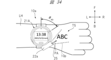
- FIG. 34 is a diagram showing a modification example of the embodiment of the portable information terminal shown in FIG. 33.
- FIG. It is a figure which shows an example of a setting information table.
- FIG. 3 is a diagram showing an example of detailed contents of a setting information table.
- FIG. 7 is a front view of a portable information terminal according to a second modification of the first embodiment.
- FIG. 7 is a side view of a portable information terminal according to a second modification of the first embodiment.
- FIG. 3 is a diagram showing a configuration example of a mobile information terminal according to Embodiment 2.
- FIG. FIG. 7 is a diagram showing a portable information terminal that is a first modification of the second embodiment.
- Embodiment 1 A portable information terminal according to Embodiment 1 will be described.
- the portable information terminal according to the first embodiment has a function of projecting an image or a moving image (hereinafter also simply referred to as an image) as display content.
- the mobile information terminal according to the first embodiment is, for example, a so-called wristwatch type that is worn on the user's arm.
- the configuration of the mobile information terminal according to Embodiment 1 will be described.
- FIG. 1A is a front view of mobile information terminal 10 according to the first embodiment.
- FIG. 1B is a side view of the mobile information terminal 10 according to the first embodiment.
- the upward direction is the front direction F
- the downward direction is the rear direction B.
- the rightward direction is the rightward direction R
- the leftward direction is the leftward direction L
- the forward direction is the upward direction U
- the forward direction is the downward direction D.
- the mobile information terminal 10 mainly includes a terminal main body 11 and an attachment 21.
- the terminal main body 11 has a circumferential peripheral edge.
- the terminal main body 11 also includes a housing 12, a touch screen section 13, a mark section 14, a belt 17, and a home button 191 as constituent elements.
- the casing 12 corresponds to a so-called housing of the terminal main body 11, and generally has a cylindrical shape with a short column axis length or a thick disk shape.
- the touch screen section 13 is provided on the surface of the housing 12, and has, for example, a rectangular shape or a disk shape.
- the touch screen section 13 has a structure in which a display section and an input section are integrated.
- the display section displays time, biological information, and other information, and is composed of display elements such as a liquid crystal panel and organic EL.
- the input unit accepts a touch operation by a user, and is configured with a capacitive touch sensor or the like.
- the mark portion 14 is arranged in a specific direction and position on the housing 12, and functions as a mark.
- the mark portion 14 is a triangular mark, and is located in the 12 o'clock direction of a typical wristwatch.
- the belt 17 is connected to the housing 12 and is for wrapping around the user's arm so that the mobile information terminal 10 is worn on the user's arm.
- the home button 191 is a physical button provided separately from the touch screen section 13 on the display surface side of the touch screen section 13 of the housing 12.
- the home button 191 is used, for example, to return displayed information to the main menu screen.
- the attachment 21 is configured to be detachable from the circumferential edge forming the side surface of the housing 12. Further, the attachment 21 is configured to be rotatable relative to the housing 12 when attached to the peripheral edge of the housing 12. Further, the attachment 21 is configured to be able to communicate with the terminal main body 11.
- the attachment 21 mainly includes a bezel section 213 and a projector section 22.
- the bezel portion 213 is configured to be attachable to the peripheral edge of the housing 12. Furthermore, when the bezel portion 213 is attached to the peripheral edge of the housing 12, it becomes an annular frame portion surrounding the display screen of the touch screen portion 13, and is configured to be rotatable with respect to the housing 12.
- the projector section 22 is provided on the bezel section 213 so as to be configured integrally with the bezel section 213.
- the projector unit 22 has a function of projecting an image representing display content onto an object such as the back of a hand, a wall, or a desk.
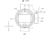
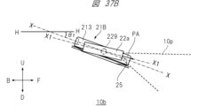
- a projection aperture 25 is formed in the projector section 22, and the projection light 10p is projected from the projection aperture 25 so as to spread toward the projection aperture direction PA, which is the central axis direction of the opening of the projection aperture 25. Note that details of the configuration of the attachment 21 will be described later.
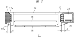
- FIG. 2 is a cross-sectional view of the portable information terminal 10 shown in FIG. 1 taken along the line AA.
- FIG. 2 shows a state in which the attachment 21 is attached to the housing 12. Further, in FIG. 2, the shaded area represents a cross section of the attachment 21.
- the mobile information terminal 10 has a physical information measurement sensor 16.
- the physical information measurement sensor 16 is arranged so as to touch the user's skin when the mobile information terminal 10 is worn on the user's arm.
- the physical information measurement sensor 16 has a function of measuring the user's pulse rate, electrocardiogram, blood flow, etc., and outputs a signal according to the measurement results.
- the housing 12 has a display surface side protrusion 12a and a sensor side protrusion 12b.
- the display surface side convex portion 12a is formed along the circumferential direction on the display surface side of the touch screen portion 13, and is a convex portion having a tapered shape.
- the sensor side convex portion 12b is a convex portion that is formed along the circumferential direction on the side of the housing 12 where the physical information measurement sensor 16 is disposed, and has a width d in the radial direction. In this way, by forming the inner circumferential side of the bezel portion 213 to follow the circumferential shape of the housing 12, the mobile information terminal 10 is configured so that the bezel portion 213 does not come off from the housing 12. .
- the portable information terminal 10 has a control board 15 inside the housing 12.
- the control board 15 controls the system of the mobile information terminal 10, the display of the touch screen section 13, and the image projected from the projector section 22 of the bezel section 213.
- the mobile information terminal 10 has an internal space 22i inside the casing of the projector section 22 provided in the bezel section 213.
- the internal space 22i houses a control board 27 of the projector unit 22, which will be described in detail later, a projection optical system (not shown), and the like.
- FIG. 3 is a front view of the terminal main body 11 viewed from the display surface side. That is, FIG. 3 shows a state in which the bezel portion 213 of the mobile information terminal 10 is removed.
- the housing 12 of the terminal body 11 is provided with pattern detection sensors 12c and 12d.
- the pattern detection sensors 12c and 12d emit light and detect the amount of reflected light according to the pattern of the reflecting surface of the emitted light. Details of the operation of these pattern detection sensors 12c and 12d will be described later.
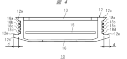
- FIG. 4 is a sectional view taken along line BB of the terminal main body 11 shown in FIG. 3.
- a plurality of grooves are formed along the circumferential side of the housing 12, and slip rings 18a to 18d are provided in these grooves.
- the bezel portion 213 rotatably fits into the slip rings 18a to 18d, and the bezel portion 213 and the slip rings 18a to 18d are configured to be electrically connectable.
- Each slip ring 18a-18d is electrically insulated between each other.
- the slip rings 18a and 18d are assigned as terminals for supplying power from the power supply included in the terminal body 11 to the bezel part 213 side
- the slip rings 18b and 18c are assigned as terminals for supplying power from the power supply included in the terminal body 11 to the bezel part 213 side
- the slip rings 18b and 18c are assigned as terminals for supplying power from the power supply included in the terminal body 11 to the bezel part 213 side
- the slip rings 18b and 18c are It is assigned as a terminal for transmitting and receiving signals to and from the bezel portion 213.
- a housing-side bezel back contact surface 12e is formed on the sensor-side convex portion 12b.
- the pattern detection sensors 12c and 12d are arranged on the case side bezel back contact surface 12e.
- the case side bezel back contact surface 12e has a width d in the radial direction of the bezel portion 213.
- FIG. 5 is a front view of the attachment 21.
- the bezel portion 213 includes a first semicircular part 211, a second semicircular part 212, a pin 23, and a fastener 24.
- the first semicircular part 211 and the second semicircular part 212 each have a generally semicircular shape, and a through hole is formed at one end in the circumferential direction.
- the pin 23 is inserted into the through holes of the first semicircular part 211 and the second semicircular part 212 in a state where these holes are overlapped, and the pin 23 is inserted into the through holes of the first semicircular part 211 and the second semicircular part 212 .
- the fastener 24 connects the first semicircular part 211 and the second semicircular part 212 when the first semicircular part 211 and the second semicircular part 212 are closed. It is to be fixed in place.
- the projector section 22 is provided near the center of the outer periphery of the second semicircular part 212 so as not to interfere with the terminal main body 11, and is configured integrally with the first semicircular part 211.
- the projector section 22 is configured to project projection light so that display content such as an image or a moving image representing characters, figures, images, etc. is projected onto an object.
- the projection aperture 25 is provided on the side surface of the projector section 22, and is an optical aperture onto which the projection light 10p is projected. Therefore, the projector section 22 integrated with the bezel section 213 can rotate together with the bezel section 213, and the spreading direction of the projection light 10p from the projector section 22 can be freely changed by 360 degrees.
- the first semicircular part 211 and the second semicircular part 212 are connected by the fastener 24 in a closed state surrounding the side surface of the housing 12, so that the bezel part 213 is connected to the terminal main body 11.
- the attachment 21 can be attached to and detached from the terminal main body 11.
- FIG. 6 is a cross-sectional view of the attachment 21 shown in FIG. 5 taken along line CC.
- a main body side bezel back contact surface 21b is formed to be in contact with the body side bezel back contact surface 12e (FIG. 4).
- the main body side bezel back contact surface 21b has a width d in the radial direction of the bezel portion 213.
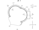
- FIG. 7 is a sectional view taken along the line DD of the attachment 21 shown in FIG. 5.
- Terminals 26a to 26d are provided in the portions of the first semicircular part 211 and the second semicircular part 212 where the projector section 22 is provided.
- the terminals 26a to 26d respectively come into contact with the slip rings 18a to 18d and are electrically connected.
- Such a configuration makes it possible to supply power from the power supply inside the housing 12 to the bezel part 213 and to transmit and receive signals between the housing 12 and the bezel part 213.
- the power supplied to the bezel section 213 is also supplied to the control board 27 and the like inside the projector section 22.
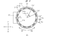
- FIG. 8 is a rear view of the attachment 21.
- a first light reflecting surface 213a shown with diagonal lines is provided on the surface of the main body side bezel back surface contact surface 21b that has a width d in the radial direction of the bezel portion 213 and extends along the circumference.
- a pattern is formed in which second light reflecting surfaces 213b indicated by diagonal lines are alternately arranged at angular intervals of ⁇ p.
- the first light reflecting surface 213a and the second light reflecting surface 213b have different light reflectances. In this embodiment, it is assumed that the light reflectance is greater than the second light reflecting surface 213b>the first light reflecting surface 213a.
- the position of the pattern detection sensor 12c (FIG. 3) when the attachment 21 is attached to the terminal body 11 is represented by position 12c'
- the position of the pattern detection sensor 12c (FIG. 3) when the attachment 21 is attached to the terminal body 11 is also represented by position 12c'
- the position of 12d (FIG. 3) is represented by position 12d'.
- FIG. 9 is a timing chart of output signals obtained by the pattern detection sensor.
- the timing chart shown in FIG. 9 shows output signals obtained by the pattern detection sensor 12c and the pattern detection sensor 12d when the attachment 21 rotates with respect to the terminal main body 11.
- the horizontal axis represents the elapsed time t.
- the detection signal of the pattern detection sensor 12c and the detection signal of the pattern detection sensor 12d are set to the "H (high)" level on the second light reflecting surface 213b, which has a relatively high reflectance, and to the "H" level on the second light reflecting surface 213b, which has a relatively low reflectance.
- the first light reflecting surface 213a outputs "L (low)".
- the output signal of the pattern detection sensor 12c becomes a pulse whose rising timing from the "L" level to the "H” level is earlier than the signal output of the pattern detection sensor 12d.
- the output signal of the pattern detection sensor 12c rises from the "L” level to the "H” level at the timing shown in FIG. The pulse is slower than the signal output from the pattern detection sensor 12d.
- the rotation angle of the bezel portion 213 with respect to the terminal body 11 can be determined by the number of pulses of the output of the pattern detection sensor 12c and the pattern detection sensor 12d, that is, the number of changes in the H level and L level. Further, the rotating direction of the bezel portion 213 is the RF direction if the signal output of the pattern detection sensor 12c is at the "H" level when the output signal of the pattern detection sensor 12d rises from the "L" level to the "H” level. If it is L'' level, it can be determined that the direction is RB.
- the terminal main body 11 and the bezel portion 213 may be configured to provide an operational feeling of rotating with a click feeling while being locked at a certain angle, for example, at each pattern interval ⁇ p of the lowest angle that can be detected. good.
- FIG. 10 is a rear view of the mobile information terminal 10.
- a reset button 192 which is a push-in physical button, is provided on the back of the terminal main body 11 of the mobile information terminal 10.
- the reset button 192 is used to initialize the measurement contents of the rotation angle and rotation direction of the bezel portion 213 when the bezel portion 213 is attached to the terminal body 11 and rotated.
- the reset button 192 is pressed, the initialization process is performed. Details of the initialization process will be described later.
- FIG. 11 is a diagram showing an example of the hardware configuration of the terminal main body 11.
- the terminal body 11 includes a communication interface (I/F) 113, a control section 114, a touch screen section 13, a microphone 161, a speaker 162, an audio input/output section 160, a home button 191, a reset button 192, Switch input section 150, storage 125, mobile communication interface (I/F) 131, memory 132, acceleration sensor 133, pulse counter 134, GPS reception section 135, gyro sensor 136, geomagnetic sensor 137, pattern detection sensor 12c, pattern detection It has a sensor 12d, a pulse counter 134, a switch input section 150, a physical information measurement sensor 16, a sensor interface (I/F) 139, an image output interface (I/F) 170, a battery 180, and slip rings 18a to 18d. Further, each functional unit except the home button 191, reset button 192, microphone 161, speaker 162, physical
- the battery 180 is a power source for the mobile information terminal 10.
- the battery 180 supplies power to each component of the terminal body 11 and to the bezel section 213 and the projector section 22 via the slip rings 18a and 18d.
- the battery 180 is, for example, a rechargeable secondary battery such as a lithium ion battery, and can be charged by a charging circuit (not shown). Further, the battery 180 supplies power to each component and the slip rings 18a and 18d via a power supply voltage conversion circuit (not shown) as necessary.
- the storage 125 stores application programs.
- the control unit 114 can realize various functions by loading an application program from the storage 125 into the memory 132 and executing the loaded application program.
- control unit 114 executing application programs will be explained as being realized mainly by various program function units.
- the application program may be stored in the storage 125 in advance before the terminal main body 11 is shipped.
- the application program is stored in a medium such as an optical medium such as a CD (Compact Disk) or a DVD (Digital Versatile Disk) or a semiconductor memory, and is installed from this medium into the terminal body 11 via a medium connection unit (not shown). Good too.
- the application program may be downloaded from an external network (not shown) and installed in the terminal main body 11 via the communication interface 113 and a wireless router (not shown).
- the application program may be downloaded from a distribution source and installed in the terminal body 11 via the mobile communication interface 131 or a base station (not shown).
- the terminal body 11 may be connected to a personal computer that has acquired the application program via a network via an external device connection interface (not shown), and the application program may be moved or copied from this personal computer to the terminal body 11 and installed. It is possible.
- the application program can also be implemented in hardware as a processing unit with similar functions.
- each processing unit takes the lead in implementing each function.
- the communication interface 113 is connected to a wireless router (not shown) via a wireless LAN (Local Area Network) or the like. Further, the communication interface 113 is connected to an external network via a wireless router, and sends and receives information to and from a server on the external network.
- a wireless router not shown
- a wireless LAN Local Area Network
- the communication interface 113 is connected to an external network via a wireless router, and sends and receives information to and from a server on the external network.
- the communication interface 113 can directly communicate with the server without going through the wireless router using technology such as wireless LAN such as Wi-Fi (registered trademark). is possible.
- the communication interface 113 may be implemented with a plurality of chips that handle different communication methods. Further, the communication interface 113 may be implemented with one chip that handles a plurality of different communication methods. The communication interface 113 may be configured to be able to communicate with other devices using a communication method called BLUETOOTH (registered trademark) for close proximity communication.
- BLUETOOTH registered trademark
- the mobile communication interface 131 is connected to a communication network through a base station using a mobile communication network such as LTE (Long Term Evolution) communication, 4G communication, or 5G communication.
- the mobile communication interface 131 is capable of transmitting and receiving information to and from a server on a communication network, and also allows terminals to share each other's locations. Note that the communication method is not limited to the above example.
- the mobile information terminal 10 may be configured to be able to prioritize connection to an external network through the communication interface 113 over communication network connection through the mobile communication interface 131.
- the control unit 114 receives a user's operation request from the home button 191 or the reset button 192 via the switch input unit 150, or from the microphone 161 via the audio input/output unit 160.
- the control unit 114 controls the touch screen unit 13, the communication interface 113, and various program function units according to the received operation request.
- control unit 114 can acquire various information from a server on an external network via the communication interface 113 and the wireless router, or via the mobile communication interface 131 and the base station.
- the control unit 114 also has a function of passing various acquired information to various program function units. Using these functions, the user can exchange images and voices with the communication partner and perform voice chats and the like.
- the storage 125 is controlled by instructions from the control unit 114 and can store application programs. Furthermore, the storage 125 stores various information created by application programs.
- the storage 125 may store content such as video and audio streams based on signals received from the communication interface 113 or the mobile communication interface 131.
- the storage 125 may be built into the mobile information terminal 10 or may be a memory mounted on a portable bezel portion 213 that is removably attached to the terminal main body 11 of the mobile information terminal 10.
- the memory 132 is controlled by instructions from the control unit 114.
- the control unit 114 expands the functional parts of the application program stored in the storage 125 into the memory 132.
- the display unit 13b that constitutes the touch screen unit 13 displays images and videos stored in the storage 125, broadcasted or distributed videos, user interfaces (UI) for various operations, images generated by application programs, etc. indicate. Note that the display unit 13b may display images and videos received from a server on an external network via the communication interface 113.
- the display unit 13b may display images and videos received from the television receiver via the communication interface 113, or may display images and videos distributed from a server on the communication network via the mobile communication interface 131. Images may also be displayed.
- the home button 191 and reset button 192 accept operations on the terminal body 11 of the mobile information terminal 10 from the user, and are input units into which control information regarding input operations is input.
- the drag operation is, for example, an operation of moving an arbitrary object such as a displayed icon on the display screen of the touch screen unit 13 while touching it with a finger.
- the flick operation is an operation in which a finger is moved on the display screen of the touch screen unit 13 in a flicking manner.
- a tap operation is an operation in which an object or the like is tapped once with a finger.
- a double tap operation is an operation in which an object or the like is tapped twice with a finger.
- each operation on the touch screen unit 13 described above will be described as a drag operation, a flick operation, and a tap operation.
- the acceleration sensor 133 measures the acceleration applied to the mobile information terminal 10.
- the geomagnetic sensor 137 measures geomagnetism at the location where the mobile information terminal 10 is present.
- the pulse counter 134 counts the pulses (FIG. 9) obtained by the pattern detection sensors 12c and 12d when the attachment 21 attached to the terminal body 11 is rotated by the user.
- the control unit 114 detects the rotation direction of the attachment 21 based on the pulse signal.
- the control unit 114 can obtain the rotational operation angle of the attachment 21 based on the detected rotational direction and the counted number of pulses.
- control unit 114 can detect which part of the terminal body 11 is upward, that is, the tilt, posture, etc. of the terminal body 11, by measuring the gravitational acceleration using the acceleration sensor 133, for example. Further, the control unit 114 can determine whether the user's arm on which the terminal body 11 is attached is the right arm or the left arm, based on the detected inclination, posture, etc. of the terminal body 11. Furthermore, the control unit 114 controls the shape of the image projected from the projector unit 22 that is integrally provided on the bezel unit 213 attached to the terminal body 11 based on the detected inclination, posture, etc. of the terminal body 11. Through control, image distortion can be corrected. The details of the amendment will be described later.
- the geomagnetic sensor 137 measures geomagnetism by using a plurality of magnetic sensors.
- the GPS receiving unit 135 receives signals transmitted from a plurality of satellites using GPS (Global Positioning System).
- the control unit 114 can calculate the position information of the terminal body 11 of the mobile information terminal 10 based on the signal received by the GPS reception unit 135.
- the gyro sensor 136 measures the angular velocity of the terminal body 11 that occurs when the terminal body 11 is moved by the user.
- the physical information measurement sensor 16 is generally configured to emit green light onto the user's arm and output a signal according to the amount of reflected light, in order to measure the user's heart rate, blood flow, etc., for example.
- the measurement target, measurement method, configuration, etc. of the physical information measurement sensor 16 are not limited to the above.
- the sensor interface 139 converts the output of the physical information measurement sensor 16 into a digital value.
- the control unit 114 processes the converted digital value using an application program to obtain the heart rate, blood flow rate, etc., and displays the heart rate, blood flow rate, etc. on the display unit 13b.
- the audio input/output unit 160 inputs/outputs an audio input signal from a microphone 161 installed in the mobile information terminal 10 and an audio output signal to the speaker 162.
- the control unit 114 controls the volume of the audio input and output.
- the switch input section 150 takes in switch information in response to the operation of the home button 191 and the reset button 192, and sends it to the control section 114 via the bus 101.
- the control unit 114 causes the switch information to be used for controlling various application programs as necessary.
- control unit 114 controls each component so that the inside of the terminal body 11 returns to the initial state and the display screen returns to the initial screen of the operating system, regardless of the operating state of the running application program. control. Details of the operation of the terminal main body 11 when the reset button 192 is pressed will be described later.
- the image output interface 170 outputs the display image generated by the control unit 114 to the outside, and exchanges information related to initialization processing when the bezel unit 213 is connected to the terminal body 11, etc., through the slip ring 18b, This is done via 18c.
- the display image is an image to be projected and displayed by the projector section 22 provided on the detachable and replaceable bezel section 213.
- FIG. 12 is a diagram showing a configuration example of the projector section 22 in the attachment 21.
- the projector section 22 includes terminals 26a to 26d, an image input interface (I/F) 203, a control section 204, a nonvolatile memory 205, a memory 206, a display element drive section 207, a projection optical system 208, It has a display element 209, an illumination optical system 210, and a light source 215.
- each functional unit of a video input interface 203, a control unit 204, a nonvolatile memory 205, a memory 206, and a display element driving unit 207 are connected to each other via a bus 201.
- Power supplied from the terminal main body 11 via the terminals 26a and 26d is supplied to each component via a power supply voltage conversion circuit (not shown) as necessary.
- the light source 215 generates light that becomes the source of the projection light 10p used for projecting images, videos, etc., and uses an LED light source, a laser light source, or the like.
- the illumination optical system 210 collects the light generated by the light source 215, makes it more uniform, and irradiates the display element 209 with the light.
- the display element 209 is an element that transmits or reflects light from the illumination optical system 210 and modulates the light at this time to generate an image.
- the display element 209 is, for example, a transmissive liquid crystal panel, a reflective liquid crystal panel, a DMD (Digital Micromirror Device: registered trademark) panel, or the like.
- the display element driver 207 sends a drive signal to the display element 209 according to the video signal.
- the projection optical system 208 is an enlarged projection optical system that projects an image, video, etc. onto a target object, and includes at least one of a lens and a mirror.
- the video signal referred to by the display element driving section 207 is a video signal input from the terminal main body 11 of the mobile information terminal 10, and is input as a differential binary signal from the terminals 26b and 26c.
- the video signal referred to by the display element driving unit 207 is an OSD (On Screen Display) generated by the control unit 204 using the image stored in the nonvolatile memory 205 and the video signal obtained via the image input interface 203. ) It may be a signal obtained by superimposing an image signal.
- the display element 209 modulates light according to a drive signal generated by the display element drive unit 207 with reference to these video signals, and generates an optical image.
- the generated optical image is projected by the projection optical system 208 as a display image using the spread of the projection light 10p.
- the protocol of signals communicated between the slip rings 18b and 18c provided on the terminal body 11 of the mobile information terminal 10 and the terminals 26b and 26c provided on the bezel portion 213 is not particularly limited. However, if existing protocols such as USB (Universal Serial Bus) are used, conventional communication software can be used, and product development costs for mobile information terminals can be reduced. As a result, portable information terminal products can be provided to users at a lower cost.
- USB Universal Serial Bus
- the mobile information terminal 10 has an initialization processing function when an attachment is attached.
- the initialization processing function when attaching an attachment means that when the attachment 21 is attached to the terminal body 11 of the mobile information terminal 10, the control unit 114 (FIG. 11) on the terminal body 11 side detects that the attachment is attached. , is the process of initializing the attachment to enable its functionality.
- FIG. 13 is a flow diagram showing the initialization process when attaching an attachment.
- step S1301 attachment attachment detection is performed. Specifically, when the user attaches the attachment 21 to the terminal main body 11, the control unit 114 detects attachment of the attachment by, for example, the same process as the process when plugging in a USB. Communication of signals representing information regarding the functions of the attachment 21 is then performed between the control unit 114 and the attachment 21 . Performing such communication processing is effective in increasing the variety of attachments. For example, as the attachment 21, one having functions other than a projector, such as one with a camera function, can be prepared.
- step S1302 it is determined whether the attachment has a projector function. Specifically, the control unit 114 determines whether the attachment 21 has a projector function based on information received from the attached attachment 21. In this determination, if it is determined that the attachment 21 has a projector function (S1302: Yes), the control unit 114 advances the processing steps to be executed to step S1303. On the other hand, in this determination, if it is determined that the projector function is not provided (S1302: No), the control unit 114 moves the processing step to be executed to step S1306.
- step S1303 a message is displayed.
- the control unit 114 controls the display unit 13b to display a message for the attachment with a projector function.
- the displayed message is, for example, a message prompting the user to align the pin 23 of the attachment 21 with the mark portion 14 and press the reset button 192 (FIG. 10).
- FIG. 14 is a diagram showing an example of message display.
- the control unit 114 causes the display screen of the display unit 13b to display a message such as ⁇ Please align the pins on the bezel with ⁇ and press the reset button on the back side.''
- step S1304 it is determined whether the reset button has been pressed. Specifically, the control unit 114 determines whether the reset button 192 has been pressed. In this determination, if it is determined that the reset button 192 has been pressed (S1304: Yes), the control unit 114 moves the processing step to be executed to the next step S1305. On the other hand, in this determination, if it is determined that the reset button 192 is not pressed (S1304: No), the processing step to be executed is returned to step S1304. Through such processing, the device enters a standby state until the reset button 192 is pressed.
- step S1305 the pulse counter 134 is reset. Specifically, the control unit 114 resets the pulse counter 134 (FIG. 11) and sets the number of pulses counted by the pulse counter 134 to zero. When this setting is completed, the initialization process ends.
- step S1306 other initialization processing for attachments that do not include a projector is performed. Specifically, the control unit 114 performs initialization processing corresponding to the functions of the attached attachment 21. After this process is performed, the initialization process ends.
- the control unit 114 After the initialization process is performed when the attachment with a projector function is attached to the terminal main body 11 in this way, the control unit 114 reads the pulse count from the pulse counter 134 almost in real time. The control unit 114 detects the rotation angle position of the bezel portion 213, that is, the attachment 21 (hereinafter also referred to as attachment rotation position) with respect to the terminal main body 11, based on the read count number.
- reset button 192 may also be used as another button, for example, the home button 191.
- Image projection control by control unit ⁇ Image projection control by control unit>
- image projection control by the control unit 114 on the terminal main body 11 side will be explained.
- the control unit 114 has a function of correcting image projection so that an image suitable for viewing is projected according to the wearing state of the mobile information terminal 10.
- Image projection control mainly includes image rotation control, image shape control, and image projection angle control. Each control will be explained below.
- the portable information terminal 10 has an image rotation control function.
- Image rotation control is a projection method that, when projecting an image as display content, maintains the vertical relationship of the image even if the attachment rotation position changes, in order to improve the visibility of the projected image. It is one of the controls.
- the control unit 114 (FIG. 11) on the side of the terminal body 11 specifies the wearing state of the portable information terminal, and controls the rotation of the image suitable for the specified wearing state according to the specified wearing state.
- FIG. 15A is a front view of the mobile information terminal 10 according to the first example.
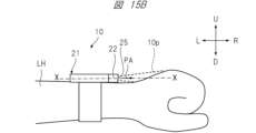
- FIG. 15B is a side view of the portable information terminal 10 according to the first embodiment.
- FIG. 16A is a front view of the portable information terminal 10 according to the second example.
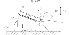
- FIG. 16B is a side view of the portable information terminal 10 according to the second example.
- the mobile information terminal 10 is worn on the outside of the user's left arm, and an image representing the letters "ABC" is projected.
- the direction of the projection aperture 25 of the projector section 22, that is, the projection aperture direction PA is set to the 3 o'clock direction, and the image T1 is projected onto the back of the left hand. There is.
- the projection opening direction PA is set to the 12 o'clock direction by rotating the attachment 21, and the image is projected onto the desk 1500 on which the user's left hand is placed. T2 is projected.
- the control unit 114 detects the rotation angle position and inclination angle of the attachment 21.
- the control unit 114 corrects the direction and spread of the projected light corresponding to the image representing the characters "ABC" in accordance with the detected rotation angle position and tilt angle of the attachment 21. This correction is performed so that the characters "ABC" represented by the projected image appear horizontal when viewed from the user.
- Such correction is mainly performed by controlling the image rotation of the displayed content, and has the effect of improving the visibility of the projected image.
- FIG. 17A is a front view of the mobile information terminal 10 according to the third example.
- FIG. 17B is a side view of the mobile information terminal 10 according to the third example.
- the mobile information terminal 10 is attached to the user's right arm RH, and an image representing the letters "ABC" is projected onto the back of the right hand.
- the portable information terminal 10 is attached to the left arm LH, but in the third embodiment shown in FIG. 17A, the portable information terminal 10 is attached to the right arm RH. Therefore, in the third embodiment, the attachment 21, that is, the bezel portion 213 itself is rotated by 180 degrees compared to the first embodiment shown in FIG. 15A. Therefore, it is necessary to display the image representing the characters "ABC" facing directly, as shown in FIG. 17A, so that the user can easily see the image.
- the control unit 114 corrects the projected image, that is, the projected light, based on the attachment rotation position so that the image is easier to see for the user.
- This correction is also mainly performed by controlling the image rotation of the displayed content, and has the effect of improving the visibility of the projected image.
- the portable information terminal 10 has an image shape control function.
- Image shape control is one type of projection control that is performed to improve the visibility of the projected image when projecting an image that is display content.
- the control unit 114 (FIG. 11) on the side of the terminal body 11 specifies the wearing state of the mobile information terminal, and controls the shape of the image suitable for the specified wearing state according to the specified wearing state.
- FIG. 18A is a front view of the mobile information terminal 10 according to the fourth example.
- FIG. 18B is a side view of the portable information terminal 10 according to the fourth example.
- FIG. 19 is a front view of the portable information terminal 10 according to the fifth embodiment.
- the mobile information terminal 10 is worn on the outside of the left arm, and an image representing a square is projected.
- the attachment 21 is rotated so that the direction of the central axis of the projection aperture 25 of the projector section 22, that is, the projection aperture direction PA is set to the 12 o'clock direction, and the user An image S1 is projected onto a desk top 1500 on which the left arm LH of a person is placed.
- the front side of the mobile information terminal 10 is naturally raised and tilted due to the structure and shape of the human skeleton, joints, or arms.
- the center line of the mobile information terminal 10, that is, the front-rear direction X is inclined with respect to the horizontal direction H at an inclination angle ⁇ r.
- the fourth example shows a state in which the image is not corrected based on the presence of the tilt angle when the image is projected onto the desk top 1500 on which the user's left arm LH is placed.
- the square represented by the image S1 is distorted into a trapezoidal shape due to the existence of the tilt angle ⁇ r from the horizontal direction H.
- control unit 114 detects the attachment rotation position and the inclination angle of the terminal body 11, and determines the direction and spread of the projected light corresponding to the image representing the square. Correct according to the detected rotation angle and tilt angle. This correction is performed so that the square represented by the projected image S2 appears to maintain its square shape when viewed from the user, as shown in FIG. Such correction is mainly performed by controlling the image shape of the displayed content, and since image distortion is reduced, it has the effect of improving the visibility of the projected image.
- the portable information terminal 10 has a function of controlling an image projection angle.
- Image projection angle control is one type of projection control that is performed to improve the visibility of the projected image when projecting an image that is display content.
- the control unit 114 (FIG. 11) on the side of the terminal main body 11 identifies the mounting state of the mobile information terminal, and controls the image projection angle suitable for the specified mounting state according to the specified mounting state.
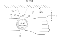
- FIG. 20A is a front view of the mobile information terminal 10 according to the sixth embodiment.
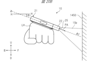
- FIG. 20B is a side view of the portable information terminal 10 according to the sixth embodiment.
- FIG. 21 is a front view of the portable information terminal 10 according to the seventh embodiment.
- the mobile information terminal 10 is attached to the outside of the user's left arm and projects an image with the projection port 25 facing the front wall 1450. .
- the attachment 21 is rotated, the projector section 22 is directed toward 12 o'clock, and an image is projected onto a wall surface 1450 in front of the user.
- the front side of the arm will lift up due to the structure and shape of the human skeleton, joints, or arm. It often leans toward
- the front-rear direction X of the mobile information terminal 10 is inclined at an inclination angle ⁇ r with respect to the horizontal direction H, and the optical axis of the projected light 10p becomes an optical axis A1 parallel to the front-rear direction X.
- the sixth embodiment shows a state in which when an image is projected onto a wall surface 1450 in front of the user, image distortion based on the presence of the tilt angle ⁇ r and projection angle correction are not performed. .
- the projected image will be distorted into a trapezoidal shape due to the presence of the tilt angle ⁇ r from the horizontal direction H. Furthermore, the position of the projected image relative to the wall surface 1450 is also shifted downward.
- the control unit 114 detects the tilt angle of the mobile information terminal 10, that is, the attitude of the terminal main body 11. Then, as in the seventh embodiment shown in FIG. 21, the control unit 114 sets the projection angle of the image upward relative to the reference projection aperture direction PA so that the image is projected almost perpendicularly to the wall surface 1450.
- the projection angle of the image is controlled so that For example, as shown in FIG. 21, the projection angle is controlled so that the optical axis of the projected light 10p becomes an optical axis A2 that is approximately perpendicular to the wall surface 1450.
- Such correction of the optical axis of the projected light 10p is mainly performed by controlling the projection angle, and the projected position of the image is changed upward to reduce image distortion. This has the effect of improving image visibility.
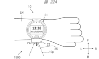
- FIG. 22A is a front view of the mobile information terminal 10 according to the eighth embodiment.
- FIG. 22B is a side view of the portable information terminal 10 according to the eighth embodiment.
- FIG. 23 is a front view of the portable information terminal 10 according to the ninth embodiment.
- the mobile information terminal 10 is worn on the outside of the user's left arm, and images that are display content are projected.
- the attachment 21 is rotated, the projection port direction PA is set to the 6 o'clock direction, and the image is projected onto the desk top 1500 on which the user's left arm LH is placed.
- the front side of the arm will lift up due to the structure and shape of the human skeleton, joints, or arm. It often leans toward
- the front-rear direction X of the mobile information terminal 10 is inclined with respect to the horizontal direction H at an inclination angle ⁇ r.
- the projection angle is not corrected based on the presence of the inclination angle ⁇ r. That is, the optical axis of the projected light 10p becomes an optical axis A3 parallel to the front-rear direction X on the display surface of the terminal main body 11.
- the projection light 10p representing the image is projected upward from the horizontal direction H due to the existence of the tilt angle ⁇ r from the horizontal direction H.
- the image is hardly projected onto the desktop 1500.
- the control unit 114 detects the inclination angle of the attachment 21, that is, the attitude of the terminal main body 11. Then, as in the ninth embodiment shown in FIG. 23, the control unit 114 controls the projection angle of the image to be downward relative to the reference projection aperture direction PA so that the image is projected onto the desk top 1500. , controls the image projection angle. For example, as shown in FIG. 23, the projection angle is controlled so that the optical axis of the projected light 10p becomes an optical axis A4 that intersects with the desk top 1500 near the left arm LH.
- Such correction of the optical axis of the projection light 10p is mainly performed by controlling the image projection angle, and the position where the image is projected is changed downward, so that the entire image is projected at a position that is easy for the user to see. At the same time, since image distortion is reduced, there is an effect of improving the visibility of the projected image.
- image rotation control and image shape control may be realized by an optical method that operates an optical system, or may be realized by an image processing method that operates image information, that is, image data.
- image processing method that operates image information, that is, image data.
- control section 114 has a function of detecting the rotation angle of the bezel section 213 and a function of detecting the tilt angle of the mobile information terminal 10 based on a predetermined mechanism or sensor.
- the control unit 114 can perform various display correction processes when projecting an image or video by the projector unit 22 based on the attachment rotation position and the terminal body posture obtained by such functions.
- Initial setting of projection control refers to setting appropriate projection control in advance according to the wearing state of mobile information terminal 10 so that images as display content are projected with good visibility.
- projection control suitable for projecting the image onto the back of the right hand is set in advance.
- rotation control is set so that the image is rotated 90 degrees clockwise so that the image is properly aligned vertically and horizontally.
- shape control is set so that the width of the image on the far side from the projection port 25 is narrower so that the trapezoidal distortion of the image is corrected.
- the projection angle control is set so that the projection angle is slightly downward from the direction of the display surface of the terminal main body 11 so that the image does not spread too much.
- the mobile information terminal 10 is worn on the outside of the user's left arm and the projection port 25 of the projector section 22 is set to face the 12 o'clock direction of the clock, the image that is the display content is It is assumed that it will be projected onto the wall in front. Therefore, in such a situation, projection control suitable for projecting the image onto the front wall is set in advance. For example, rotation control is set so that the image is not rotated so that the top, bottom, right, and left sides of the image are appropriate. Furthermore, due to the structure of the human body, it is natural for the outside of the arm to lean toward the wall in front of it, so there is a strong tendency for the image to be projected diagonally downward toward the wall. Therefore, the projection angle control is set so that the image is projected perpendicularly to the wall and the projection direction is slightly upward from the direction of the display surface of the terminal main body 11.
- image shape control may be set instead of projection angle control, or conversely, projection angle control may be set instead of image shape control.
- projection angle control and image shape control may be set simultaneously.
- the initial settings for projection control include whether the mobile information terminal 10 is attached to the left or right side or outside or inside of the arm, and the direction of the projection port 25. It may also be determined based on the attitude of the terminal main body 11, that is, the direction and degree of inclination.
- the control unit 114 identifies the wearing state of the mobile information terminal 10 when an image that is display content is projected, and performs projection appropriate for the specified wearing state. Perform initial control settings.
- the mounting state of the mobile information terminal 10 includes the mounting position of the mobile information terminal, the rotational position of the attachment, the attitude of the terminal body, and the like.
- the mounting position outside of the left arm, outside of the right arm, inside of the left arm, and inside of the right arm.
- 12 kinds of options are prepared for the position of the pin 23 of the bezel portion 213, which are positions in 1-hour increments from the 12 o'clock direction to the 11 o'clock direction of the watch.
- the terminal body posture is horizontal, front upward tilt (small), rear upward tilt (small), left upward tilt (small), right upward tilt (small), front upward tilt (large), rear upward tilt (large),
- Nine options are available: upper left tilt (large) and upper right tilt (large).
- a plurality of different setting information is stored in the storage 125.
- the plurality of different setting information are such that the wearing state of the mobile information terminal 10 is associated with setting information representing the initial setting of projection control suitable for the wearing state.
- the control unit 114 reads setting information corresponding to the specified wearing state from the storage 125, and performs initial settings for projection control based on the read setting information.
- FIG. 24 is a diagram showing an example of the setting information table.
- the setting information table is prepared in which, for example, setting information for projection control that is set for each mounting position of the mobile information terminal is compiled.
- a setting information table T01 is applied when the mobile information terminal 10 is worn on the outside of the left arm
- a setting information table T02 is applied when the mobile information terminal 10 is worn on the outside of the right arm
- a setting information table T02 is applied when the mobile information terminal 10 is worn on the outside of the left arm.
- a setting information table T03 is shown which is applied when the wear position is on the inside of the right arm
- a setting information table T04 is shown which is applied when the wearing position is on the inside of the right arm.
- these setting information tables T01 to T04 are stored in the storage 125.
- the setting information table may be one table.
- the setting information table may be stored in the memory 132 on the terminal main body 11 side, or may be stored in the memory 206 on the attachment 21 side.
- FIG. 25 is a diagram showing an example of detailed contents of the setting information table T01.
- FIG. 25 is shown as a representative example of the setting information tables T01 to T04 to facilitate understanding of the table.
- the items "attachment rotation position” and “terminal body posture” are provided as combination items, assuming that the attachment position is “outside” of the "left arm”.
- "setting information” corresponding to the combination of these items is associated. Note that here, each setting information is represented by a symbol J (j1, j2, j3, j4).
- j1 is a numerical value depending on whether the mounting position is on the left or right side of the arm
- j2 is a numerical value depending on whether the mounting position is outside or inside the arm
- j3 is a numerical value depending on the attachment rotation position
- j4 is a numerical value depending on the attitude of the terminal body.
- the "attachment rotational position” is also the rotational position of the attachment 21, and the rotational position of the projector unit 22, for example, the position of the pin 23 as its reference position, is the position of the time direction on a general clock. This is information indicating. Specifically, the "attachment rotational position" indicates which one is the 12 o'clock direction, the 1 o'clock direction, the 2 o'clock direction, . . . , the 11 o'clock direction.
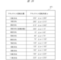
- FIG. 26 is a diagram representing a table AP1 showing an example of the correspondence between the attachment rotation position and the attachment rotation angle ⁇ .
- the bezel rotation angle ⁇ is set to 0° when the projector section is located in the 3 o'clock direction due to initialization when the bezel is attached. As shown in FIG. 26, for example, when 345° ⁇ 15°, the attachment rotation position is in the 3 o'clock direction. Further, for example, when 255° ⁇ 285°, the attachment rotation position is in the 12 o'clock direction.
- the "terminal body posture” is information indicating which direction and how much the display surface of the terminal body 11 is tilted.
- device body posture is horizontal, front-up tilt (small), rear-up tilt (small), right-up tilt (small), left-up tilt (small), front-up tilt (large), and rear-up tilt. (large), upper right tilt (large), or upper left tilt (large).
- front upward inclination (small) means that the front of the terminal main body 11 is inclined upward at a small angle.
- the upper right tilt (large) means that the right side of the terminal body 11 is tilted upward at a large angle.
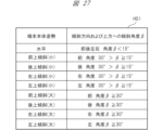
- FIG. 27 is a diagram representing a table HS1 showing an example of the correspondence between the terminal body posture, the tilt direction of the terminal body, and the upward tilt angle ⁇ .
- the inclination angle ⁇ is 0° when the display surface of the terminal main body 11 is horizontal. figure? As shown in FIG. 2, for example, when the upward tilt angle ⁇ 15° in the front, rear, left, and right directions, the terminal main body attitude is horizontal. Further, for example, when the inclination direction is forward and 30°> ⁇ 15°, the forward inclination becomes (small). Further, for example, when the inclination direction is rightward and ⁇ 30°, the upper right inclination is (large).
- FIG. 28 is a diagram showing an example of the contents of the setting information associated in the setting information table T01.
- a table T11 showing an example of the contents of setting information is shown.
- the setting information J (1, 1, 12, 1) indicates that the mounting position of the mobile information terminal 10 is on the outside of the left arm, the attachment rotation position is in the 12 o'clock direction, and the terminal body posture is This is the setting information when it is horizontal.
- the setting contents of the setting information include settings for rotation control, shape control, and projection angle control of display content.
- the setting contents of the setting information J (1, 1, 12, 1) are that for the rotation control of the display content, the rotation is 0°, and for the shape control of the display content, the setting is linear or There is no shape correction, and the projection angle control is set to 0°.
- the settings of the setting information J (1, 1, 6, 3) are as follows: For the rotation control of the display content, the rotation is 180 degrees clockwise (CW), and for the shape control of the display content, Correction is performed to narrow the far width of the image, and the projection angle is set to be 30 degrees downward.
- the control unit 114 refers to the setting information table described above, reads setting information according to the detected wearing state, and performs initial settings for projection control based on the setting information.
- the wearing state and setting information are explained in a simple manner for ease of understanding, but in reality, the wearing state and setting information may be defined by more complex and detailed items. Conceivable. According to such a configuration that performs initial settings for projection control, since projection control suitable for the wearing state of the mobile information terminal is performed in advance, there is no need for subsequent adjustment of projection control, or subsequent projection control by the user. The visibility of displayed content can be improved just by making small adjustments.
- the initial setting of projection control may be performed based on information input by the user.
- the user may input the wearing state of the mobile information terminal 10, and the control unit 114 may initialize the projection control suitable for the input wearing state.
- the user may directly perform initial settings, current settings, fine adjustments, etc. of the projection control.
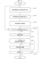
- FIG. 29 is a flow diagram illustrating an example of a process for automatically determining whether the arm on which the mobile information terminal 10 is attached is left or right.
- the flowchart shown in FIG. 29 represents an example of a processing procedure by the control unit 114 for determining whether the mobile information terminal 10 is worn on the left or right arm of the user.
- This discrimination processing algorithm is based on the premise that the user often has his or her arms hanging downward (in the direction of gravity) while walking.
- step S2901 it is determined whether the person is walking. Specifically, the control unit 114 determines whether the user wearing the mobile information terminal 10 is walking based on the output history of at least one of the acceleration sensor 133 and the gyro sensor 136 over a certain period of time. .
- the output of the acceleration sensor 133 or the gyro sensor 136 repeats changes with an amount of change greater than a certain level. Therefore, it can be determined whether the person is walking based on whether or not such characteristics are recognized.
- control unit 114 advances the step to be executed to S2902. On the other hand, if it is determined that the user is not walking (S2901: No), the control unit 114 moves the step to be executed to S2906.
- step S2902 it is determined whether the direction of gravity of the mobile information terminal 10 is in the 3 o'clock direction. Specifically, the control unit 114 determines whether the direction of gravity of the mobile information terminal 10 is near the 3 o'clock direction of the wristwatch based on the output of the acceleration sensor 133. In this determination, if it is determined that the direction of gravity is near the 3 o'clock direction (S2902: Yes), the control unit 114 advances the step to be executed to S2904. On the other hand, if it is determined that the direction of gravity is not near the 3 o'clock direction (S2902: No), the control unit 114 moves the step to be executed to S2903.
- step S2903 it is determined whether the direction of gravity of the mobile information terminal 10 is the 9 o'clock direction. Specifically, the control unit 114 determines, based on the output of the acceleration sensor 133, whether the direction of gravity of the mobile information terminal 10 is near the 9 o'clock direction of the wristwatch. In this determination, if it is determined that the gravity direction is near the 9 o'clock direction (S2903: Yes), the control unit 114 advances the step to be executed to S2905. On the other hand, if it is determined that the gravity direction is not near the 3 o'clock direction (S2903: No), the control unit 114 moves the step to be executed to S2906.
- step S2904 as a process executed when it is determined that the user is walking and the gravity direction of the acceleration sensor output is in the 3 o'clock direction, a process of counting up the variable LW corresponding to the determination result. will be held. Specifically, the control unit 114 sets a value obtained by adding 1 to the value of the variable LW as a new value of the variable LW. When step S2904 is executed, the control unit 114 moves the step to be executed to S2906.
- step S2905 as a process to be executed when it is determined that the user is walking and the gravity direction of the acceleration sensor output is in the 9 o'clock direction, a process of counting up the variable RW corresponding to the determination result is performed. It will be done. Specifically, the control unit 114 sets a value obtained by adding 1 to the value of the variable RW as the new value of the variable RW. When step S2905 is executed, the control unit 114 moves the step to be executed to S2906.
- variables LW and RW are variables used in the program of the control unit 114, and are initialized when the mobile information terminal 10 is turned on or when a system reset process (not shown) is performed by the user. and the value shall be zero.
- step S2906 it is determined whether or not there is a significant difference between the values of variable LW and variable RW. Specifically, the control unit 114 determines whether either the value of the variable LW or the value of the variable RW exceeds the threshold value TH1, and the ratio of the value of the variable LW to the total count number and the ratio of the value of the variable RW. It is determined whether there is a situation in which the difference between the two values exceeds a threshold value TH2. If it is determined that such a situation exists, the control unit 114 advances the step to be executed to S2907. On the other hand, if it is determined that such a situation does not exist, the control unit 114 returns the step to be executed to S2901.
- step S2907 the value of variable LW and the value of variable RW are compared. Specifically, the control unit 114 determines which of the following relationships holds: (1) value of variable LW>value of variable RW, or (2) value of variable LW ⁇ value of variable RW.
- the control unit 114 determines that the user is wearing the mobile information terminal 10 on his left arm (S2908), and ends the determination process.
- the control unit 114 determines that the user is wearing the mobile information terminal 10 on his right arm (S2909), and ends the determination process.
- the physical information measurement sensor 16 irradiates the object with a green light source and outputs a signal according to the amount of light reflected from the object.
- the thickness or number of blood vessels passing near the surface of the arm that is, the blood flow rate, differs between the outside of the arm (on the back of the hand) and the inside of the arm (on the opposite side of the hand).
- the amount of reflected green light varies depending on the blood flow rate. That is, the physical information measurement sensor 16 outputs different signals depending on whether the outside of the arm is irradiated with the green light or the inside of the arm is irradiated with the green light. By utilizing such characteristics, it is possible to determine whether the portable information terminal 10 is worn on the outside or inside of the arm based on the output of the physical information measurement sensor 16.
- FIG. 30 is a flow diagram illustrating an example of a process for determining whether the arm on which the mobile information terminal 10 is attached is inside or outside.
- step S3001 light is emitted to the arm.
- the control unit 114 controls the physical information measurement sensor 16, and the physical information measurement sensor 16 emits green light to the user's arm.
- step S3002 the light reflectance of the arm is measured.
- the control unit 114 receives a signal output from the physical information measurement sensor 16, detects the amount of green light emitted from the arm and reflected from the arm, and detects the amount of green light emitted from the arm based on the amount of light reflected from the arm. Measure light reflectance.
- step S3003 it is determined whether the measured light reflectance exceeds a threshold value. Specifically, the control unit 114 determines whether the measured light reflectance of the arm exceeds a predetermined threshold th. In this determination, if it is determined that the light reflectance exceeds the threshold th (S2003: Yes), the control unit 114 advances the processing step to step 3004. On the other hand, if it is determined that the light reflectance does not exceed the threshold th (S3003: No), the control unit 114 advances the processing step to step S3005.
- step S3004 the control unit 114 determines that the mobile information terminal 10 is worn on the outside of the user's arm. On the other hand, in step S3005, the control unit 114 determines that the mobile information terminal 10 is worn on the inside of the user's arm.
- FIG. 31 is a flow diagram illustrating an example of a process related to display content projection on the mobile information terminal 10.
- step S3101 the mounting state of the mobile information terminal 10 is identified.
- the control unit 114 specifies the terminal mounting position, the attachment rotation position, and the terminal body posture as items regarding the mounting state of the mobile information terminal 10. For example, the method described above is used to specify each item of the wearing state.
- step S3102 projection control setting information is read.
- the control unit 114 refers to the setting information table stored in the storage 125 and reads out from the storage 125 the projection control setting information associated with the specified combination of wearing state items. That is, the control unit 114 reads out projection control setting information suitable for the specified wearing state according to the specified wearing state.
- step S3103 initial settings for projection control are performed. Specifically, the control unit 114 performs initial settings for image rotation control, image shape control, and image projection angle control based on the read setting information.
- step S3104 it is determined whether there has been a change in the attachment rotational position. Specifically, the control unit 114 determines whether there has been a change in the attachment rotational position detected almost in real time. In this determination, if it is determined that there has been a change (S3104: No), the control unit 114 returns the processing step to step S3101. On the other hand, in this determination, if it is determined that there is no change (S3104: Yes), the control unit 114 advances the processing step to step S3105.
- step S3105 image projection is performed. Specifically, the control unit 114 corrects the image by performing set image rotation control and image shape control on the image that is the display content. Then, the control unit 114 transmits image information representing the corrected image, that is, image data, and setting information for projection angle control to the projector unit 22. The control unit 204 on the projector unit 22 side controls the projection angle based on the received projection angle control setting information. Further, the control unit 204 projects an image represented by the received image data by controlling each unit related to image projection.
- step S3106 a process is performed to determine whether or not projection control, display content rotation control, shape control, and projection angle control are adjusted by user operations.
- the control unit 114 executes processing to detect a user's operation, and when a user's operation is detected, adjusts projection control and rotates display content based on information input by the user. Determine if there are any adjustments to control, shape control, and projection angle control. In this determination, if it is determined that there is an adjustment (S1506: Yes), processing is performed to advance the processing step to step S1507. On the other hand, if it is determined that there is no adjustment (S1506: No), the process proceeds to step S1508.
- step S1507 a process of adjusting projection control is performed. Specifically, the control unit 114 adjusts the projection control based on projection control adjustment information input by the user's operation.
- step S1508 it is determined whether or not to end the projection. Specifically, the control unit 114 checks whether a reason for terminating the projection has occurred. Possible reasons for terminating the projection include, for example, an error has occurred in the process, or an instruction to terminate the projection has been input by a user operation. If a reason for terminating the projection occurs, it is determined that the projection has ended, and if a reason for terminating the projection does not occur, it is determined that the projection has not ended. In this determination, if it is determined that the projection has ended (S3108: Yes), the projection is ended. On the other hand, if it is determined that the projection has not ended (S3108: No), the control unit 114 returns the processing step to step S1504.
- a reason for terminating the projection include, for example, an error has occurred in the process, or an instruction to terminate the projection has been input by a user operation. If a reason for terminating the projection occurs, it is determined that the projection has ended, and if a reason for terminating the projection does not occur,
- the mobile information terminal according to the first embodiment since the mobile information terminal according to the first embodiment has the function of image rotation control, when projecting an image as display content, the projected image is rotated by the mobile information terminal. It can be rotated to a rotation angle suitable for the wearing condition. For example, even if the direction in which the image is projected changes, the horizontality of the image can be maintained. As a result, visibility of displayed content can be improved. Particularly when sharing display content with a person other than the user, it becomes possible to project the display content with good visibility even for the person other than the user.
- the mobile information terminal since it has an image shape control function, when projecting an image as display content, the image is shaped into a shape suitable for the state in which the mobile information terminal is worn. It can be transformed into. For example, if the surface of the object onto which the image is projected is tilted with respect to the projection direction, the image will have trapezoidal distortion, but such trapezoidal distortion can be corrected. As a result, visibility of displayed content can be improved. Particularly when sharing display content with a person other than the user, it becomes possible to project the display content with good visibility even for the person other than the user.
- the mobile information terminal since it has a projection angle control function, when projecting an image that is display content, the projection angle is adjusted to suit the wearing state of the mobile information terminal.
- the angle can be adjusted. For example, if the surface of the object onto which the image is projected is tilted with respect to the projection direction, the image will have trapezoidal distortion, but such trapezoidal distortion can be corrected. As a result, visibility of displayed content can be improved. In particular, when display content is shared with a person other than the user, the visibility of the display content is improved even for the person other than the user.
- the mobile information terminal based on the identified wearing state of the mobile information terminal, initial setting of projection control suitable for the projection form of display content assumed from the wearing state is performed. Therefore, the visibility of the projected display content can be further improved. In particular, when display content is shared with a person other than the user, the visibility of the display content is improved even for the person other than the user.
- the mounting state of the mobile information terminal that is, the mounting position, the attachment rotation position, and the terminal main body posture can be automatically detected using the sensor, and the projection It is possible to automatically initialize control settings, which is convenient for the user.
- the attachment is removable, and attachments that have functions other than the projector function, such as those that have a projector function and those that have a camera function, can be attached to the terminal body. It can be installed. According to the portable information terminal having such a configuration, the user can use an attachment suitable for the purpose, which is convenient for the user.
- an attachment having a projector function can be rotatably attached to the terminal body.
- the mobile information terminal according to the first modification example includes an attachment that is provided with a projector part whose projection opening direction is different from the radial direction of the circumference of the bezel part, as an attachment option that can be attached to the terminal body.
- the direction of the projection opening is, for example, the tangential direction of the circumference of the bezel portion.
- FIG. 32A is a front view of the mobile information terminal 10a according to the first modification of the first embodiment.
- FIG. 32B is a side view of the mobile information terminal 10a.
- the projection port of the projector section 22a in the attachment 21A that is, the opening that is the exit of the projected light 10p is formed at one end in the longitudinal direction of the projector section 22a. has been done. That is, in the portable information terminal 10a of this embodiment, the projection opening direction PA of the projector section 22a is set to be the tangential direction of the circumference of the bezel section 213.
- FIG. 33 is a diagram showing an embodiment of the mobile information terminal 10a.
- the mobile information terminal 10a is attached to the outside of the user's left arm LH, and the projection light 10p corresponding to the image T4 representing the characters "ABC" which is the display content is transmitted from the projector unit 22 to the back of the user's hand. is projected on.
- the bezel portion 213 is rotated by a rotation angle ⁇ d1 in order to project an image onto the back of the user's left arm LH.
- the control unit 114 does not perform rotation control of the projected image. In other words, an image without rotation correction is projected onto the back of the hand. In this case, the characters "ABC" appear to be tilted diagonally to the user.
- FIG. 34 is a diagram showing a modification to the embodiment of the mobile information terminal 10a shown in FIG. 33.
- the control unit 114 detects the rotation angle ⁇ d1 of the attachment 21A, and changes the shape of the image based on the rotation angle ⁇ d1 so that the letters "ABC" are displayed along the longitudinal direction of the arm. to correct. Therefore, according to this configuration, it appears to the user that the characters "ABC" are displayed in the horizontal direction, that is, along the longitudinal direction of the arm, and the visibility of the projected image is improved.
- FIG. 35 is a diagram showing an example of a setting information table.
- the setting information table is prepared in which, for example, setting information of projection control to be set is compiled for each mounting position of the information terminal.
- a setting information table T11 is applied when the mobile information terminal 10a is worn on the outside of the left arm
- a setting information table T12 is applied when the mobile information terminal 10a is worn on the outside of the right arm
- a setting information table T12 is applied when the mobile information terminal 10a is worn on the outside of the left arm.
- a setting information table T13 is shown which is applied when the item is worn
- a setting information table T14 is shown which is applied when the wearing position is on the inside of the right arm.
- these setting information tables T11 to T14 are stored in the storage 125.
- FIG. 36 is a diagram showing an example of detailed contents of the setting information table T11.
- FIG. 36 is shown as a representative example of the setting information tables T11 to T14 to facilitate understanding of the table.
- the setting information table T11 as combination items, in addition to "attachment rotation position" and “terminal body posture", assuming that the attachment position is “outside” of "left arm", An item of "projection port direction” is provided, and "setting information" corresponding to the combination of these items is associated.
- the "projection aperture direction” is information representing the direction of the optical axis or principal axis of the projection light 10p emitted from the projection aperture 25.
- the “projection aperture direction” for example, “radial direction” and “tangential direction” of the circumference of the bezel portion 213 are prepared.
- the portable information terminal according to the second modification has an attachment that allows the projector section to rotate with respect to the bezel section, as an attachment option that can be attached to the terminal main body. That is, the portable information terminal according to the second modification is configured to be able to change the image projection direction by changing the rotational position of the projector unit.
- FIG. 37A is a front view of the mobile information terminal 10b according to the second modification of the first embodiment. Further, FIG. 37B is a side view of the mobile information terminal 10b according to the second modification of the first embodiment.
- the mobile information terminal 10b includes an attachment 21B in which the projector section 22a is configured to be rotatable with respect to the bezel section 213.
- the attachment 21B includes a rotation mechanism 229 that allows the projector section 22a to rotate relative to the bezel section 213 about a direction parallel to the display surface direction of the terminal main body 11.
- the projection aperture direction PA of the projector section 22a is the tangential direction of the circumference of the bezel section 213, as in the first modification.
- the mounting state of the mobile information terminal includes the item "rotation angle of projector unit”.
- “Projector unit rotation angle” is information representing the rotation angle of the projector unit 22a with respect to the bezel unit 213, that is, information indicating the rotational state of the projector unit 22a.
- the control unit 114 performs initial settings for projection control that are considered suitable for the mounting state of the mobile information terminal, depending on a combination of a plurality of items including the "rotation angle of the projector unit.” That is, the setting information table is a table that includes "projector unit rotation angle", which is the rotational state of the projector unit 22a, as one of the items associated with the setting information.
- Embodiment 2 A portable information terminal according to Embodiment 2 will be described.
- the mobile information terminal according to the first embodiment has a rotating bezel type attachment
- the mobile information terminal according to the second embodiment has a terminal connection type attachment. . That is, the projection direction of the image can be changed depending on the connection position of the attachment to the terminal body.
- FIG. 38 is a diagram illustrating a configuration example of a mobile information terminal 10c according to the second embodiment.
- the portable information terminal 10c has a terminal main body 11c that is approximately rectangular in shape.
- the terminal main body 11c has a plurality of different connection terminals, and these connection terminals are respectively provided in four directions of the top, bottom, left and right of the terminal main body 11c.
- the attachment 21C which is integrated with the projector section, is configured to be able to be inserted into and removed from each of the connection terminals provided in the four directions of the top, bottom, right and left of the terminal body 11c.
- the direction in which the image or video is projected from the attachment 21C is the same as that shown in FIG. That is, in a state where the attachment 21C is attached to the terminal body 11c, an image or video is projected on the side opposite to the side of the terminal body 11c.
- the direction of the projection port is determined by the mounting position of the attachment 21C on the terminal main body 11c. Therefore, the pattern detection sensors 12c and 12d for detecting the rotation angle of the attachment 21C necessary for correcting the projected image, the detection pattern as a rotary encoder on the bezel portion 213 side, etc. are no longer necessary, simplifying the structure of the mobile information terminal. can be converted into
- the mobile information terminal according to the first modification example includes an attachment that is provided with a projector section whose projection opening direction is different from the direction of radiation from the center of the terminal body, as an attachment option that can be attached to the terminal body.
- the projection opening direction is, for example, a direction perpendicular to the radial direction from the center of the terminal body.
- FIG. 39 is a diagram showing a mobile information terminal 10d that is a first modification of the second embodiment.
- the mobile information terminal 10d has an attachment 21D integrated with the projector section.
- the projection opening direction PA of the projector unit in the attachment 21D is a direction perpendicular to the radial direction from the center of the terminal main body 11, and specifically, the direction PA of the projector section is the longitudinal direction of the attachment 21D. That is, the projection port of the projector section of the attachment 21D is formed at one end in the longitudinal direction of the attachment 21D.
- the projection port direction PA is determined by the mounting position of the attachment 21D with respect to the terminal main body 11c. Therefore, the pattern detection sensors 12c and 12d for detecting the rotational position of the attachment required for image correction, the detection pattern as a rotary encoder on the attachment 21D side, etc. are not required, and the structure of the portable information terminal can be simplified.
- the optical projection angle with respect to the projector unit is assumed to be unchanged.
- the attachment or the projector section may be configured such that all or part of the optical system of the projector section is mechanically variable, and the control section may control the angle thereof.
- a gyro sensor is mounted on the terminal body of the mobile information terminal in Embodiments 1 to 3. Therefore, for example, when a user is wearing a mobile information terminal on their arm and projects an image onto a wall in front of them, vibrations in the user's arm and camera shake can be detected, and image processing can be used to correct the camera shake. be able to.
- the electrical connection between the power source and the signal between the terminal main body of the portable information terminal and the attachment is realized using a slip ring and a terminal.
- the electrical connection of signals may be realized by close proximity wireless connection, or the electrical connection of the power source may be realized by wireless power supply, and the electrical connection of signals may be realized by close proximity wireless connection. It may be realized by wireless connection. According to such a configuration, since the number of sliding parts of the electrical connection part can be reduced, it is possible to reduce mechanical wear and tear, and it is easy to create a waterproof structure. Furthermore, it is also possible to reduce manufacturing costs.
- Embodiments 1 to 3 an example was shown in which a mobile communication interface is mounted on the main body of a portable information terminal.
- the mobile communication interface may be mounted not on the main body but on the detachable attachment side.
- attachments having different functions may be prepared, for example, attachments having a communication function such as LTE, and attachments having an imaging function. In this way, the user can freely expand the functions of the mobile information terminal by later acquiring an attachment having the necessary functions as needed. In other words, the product configuration of the mobile information terminal can be made functionally expandable.
- projection control that is, image rotation control, image shape control, and projection angle control
- a control unit on the terminal main body side acquires information necessary for the above projection control using a sensor, etc., transmits that information to the attachment, and the control unit on the attachment side performs the above projection control based on the received information. You can do it like this.
- the control unit on the terminal body side sends information about the image to be projected to the attachment, and the control unit on the attachment side acquires the information necessary for the projection control using a sensor mounted on itself, and then transmits the information on the image to be projected. Control may also be performed.
- each of the embodiments described above may be partially or entirely configured by hardware, or may be configured to be realized by executing a program on a processor.
- control lines and information lines are shown to be necessary for explanation purposes, and not all control lines and information lines are necessarily shown in the product. In reality, almost all components may be considered to be interconnected.
Landscapes
- Engineering & Computer Science (AREA)
- Theoretical Computer Science (AREA)
- Computer Hardware Design (AREA)
- Physics & Mathematics (AREA)
- General Physics & Mathematics (AREA)
- General Engineering & Computer Science (AREA)
- Human Computer Interaction (AREA)
- Telephone Set Structure (AREA)
- Controls And Circuits For Display Device (AREA)
- Geometry (AREA)
- Multimedia (AREA)
- Signal Processing (AREA)
- Position Input By Displaying (AREA)
Priority Applications (5)
| Application Number | Priority Date | Filing Date | Title |
|---|---|---|---|
| JP2024545321A JP7796238B2 (ja) | 2022-09-07 | 2022-09-07 | 携帯情報端末、端末本体、およびアタッチメント |
| US19/109,596 US20260099172A1 (en) | 2022-09-07 | 2022-09-07 | Portable information terminal, terminal body, and attachment |
| CN202280097611.5A CN119365916A (zh) | 2022-09-07 | 2022-09-07 | 便携信息终端、终端主体和附件 |
| PCT/JP2022/033517 WO2024053002A1 (ja) | 2022-09-07 | 2022-09-07 | 携帯情報端末、端末本体、およびアタッチメント |
| JP2025273132A JP2026040570A (ja) | 2022-09-07 | 2025-12-22 | 携帯情報端末、端末本体、およびアタッチメント |
Applications Claiming Priority (1)
| Application Number | Priority Date | Filing Date | Title |
|---|---|---|---|
| PCT/JP2022/033517 WO2024053002A1 (ja) | 2022-09-07 | 2022-09-07 | 携帯情報端末、端末本体、およびアタッチメント |
Publications (1)
| Publication Number | Publication Date |
|---|---|
| WO2024053002A1 true WO2024053002A1 (ja) | 2024-03-14 |
Family
ID=90192431
Family Applications (1)
| Application Number | Title | Priority Date | Filing Date |
|---|---|---|---|
| PCT/JP2022/033517 Ceased WO2024053002A1 (ja) | 2022-09-07 | 2022-09-07 | 携帯情報端末、端末本体、およびアタッチメント |
Country Status (4)
| Country | Link |
|---|---|
| US (1) | US20260099172A1 (https=) |
| JP (2) | JP7796238B2 (https=) |
| CN (1) | CN119365916A (https=) |
| WO (1) | WO2024053002A1 (https=) |
Citations (7)
| Publication number | Priority date | Publication date | Assignee | Title |
|---|---|---|---|---|
| JP2003038217A (ja) * | 2001-07-31 | 2003-02-12 | Masanori Taura | 携帯電話機用リストバンド |
| JP2007096542A (ja) * | 2005-09-27 | 2007-04-12 | Sharp Corp | プロジェクタ機能付携帯端末 |
| JP2010246030A (ja) * | 2009-04-09 | 2010-10-28 | Panasonic Corp | 携帯端末装置及びホルダ |
| CN206209303U (zh) * | 2016-10-13 | 2017-05-31 | 无锡科技职业学院 | 一种led教学投影钟 |
| JP2020024569A (ja) * | 2018-08-07 | 2020-02-13 | Ntn株式会社 | リストバンド |
| CN111067206A (zh) * | 2020-01-14 | 2020-04-28 | 江苏感恩机械有限公司 | 一种具有投影功能的穿戴式电子智能手表 |
| CN215991068U (zh) * | 2021-08-05 | 2022-03-08 | 上海旗胜电器有限公司 | 一种可视化网络交互显示装置 |
Family Cites Families (36)
| Publication number | Priority date | Publication date | Assignee | Title |
|---|---|---|---|---|
| US6771294B1 (en) * | 1999-12-29 | 2004-08-03 | Petri Pulli | User interface |
| WO2010024028A1 (ja) * | 2008-08-29 | 2010-03-04 | 日本電気株式会社 | 位置情報入力装置および位置情報入力方法 |
| JP2010170048A (ja) | 2009-01-26 | 2010-08-05 | Toshiba Corp | プロジェクター装置 |
| US9569001B2 (en) * | 2009-02-03 | 2017-02-14 | Massachusetts Institute Of Technology | Wearable gestural interface |
| US9958902B2 (en) * | 2010-03-15 | 2018-05-01 | Nec Corporation | Input device, input method, and program |
| US8228315B1 (en) * | 2011-07-12 | 2012-07-24 | Google Inc. | Methods and systems for a virtual input device |
| US9582035B2 (en) * | 2014-02-25 | 2017-02-28 | Medibotics Llc | Wearable computing devices and methods for the wrist and/or forearm |
| CN105027030B (zh) * | 2012-11-01 | 2018-10-23 | 艾卡姆有限公司 | 用于三维成像、映射、建网和界面连接的无线腕式计算和控制设备和方法 |
| US10142496B1 (en) * | 2013-01-26 | 2018-11-27 | Ip Holdings, Inc. | Mobile device image capture and image modification including filters, superimposing and geofenced comments in augmented reality |
| KR101999958B1 (ko) * | 2013-05-22 | 2019-07-15 | 엘지전자 주식회사 | 이동 단말기 및 그것의 제어 방법 |
| JP2015041052A (ja) * | 2013-08-23 | 2015-03-02 | ソニー株式会社 | リストバンド型情報処理装置および記憶媒体 |
| CN104866170B (zh) * | 2014-02-24 | 2018-12-14 | 联想(北京)有限公司 | 一种信息处理方法及电子设备 |
| US11747769B2 (en) * | 2014-02-25 | 2023-09-05 | Medibotics Llc | Smart watch with variable-configuration display |
| US10429888B2 (en) * | 2014-02-25 | 2019-10-01 | Medibotics Llc | Wearable computer display devices for the forearm, wrist, and/or hand |
| US20150323998A1 (en) * | 2014-05-06 | 2015-11-12 | Qualcomm Incorporated | Enhanced user interface for a wearable electronic device |
| WO2016060461A1 (en) * | 2014-10-15 | 2016-04-21 | Jun Ho Park | Wearable device |
| KR101909540B1 (ko) * | 2014-10-23 | 2018-10-18 | 삼성전자주식회사 | 가상의 입력 영역을 이용한 포터블 디바이스의 사용자 입력 방법 |
| KR102029756B1 (ko) * | 2014-11-03 | 2019-10-08 | 삼성전자주식회사 | 웨어러블 디바이스 및 그 제어 방법 |
| KR20160055577A (ko) * | 2014-11-10 | 2016-05-18 | 엘지전자 주식회사 | 웨어러블 디바이스 |
| KR101518395B1 (ko) * | 2014-11-17 | 2015-05-15 | 구본훈 | 스마트 레이저 폰 |
| KR101927323B1 (ko) * | 2015-04-03 | 2018-12-10 | 엘지전자 주식회사 | 이동단말기 및 그 제어방법 |
| FR3034889B1 (fr) * | 2015-04-10 | 2017-04-28 | Cn2P Sas | Bracelet electronique pour l’affichage d’un contenu numerique interactif destine a etre projete sur une zone d’un bras |
| FR3034890B1 (fr) * | 2015-04-10 | 2018-09-07 | Cn2P | Dispositif electronique de projection interactif |
| JP6288372B2 (ja) * | 2015-05-21 | 2018-03-07 | 日本電気株式会社 | インタフェース制御システム、インタフェース制御装置、インタフェース制御方法、及びプログラム |
| CN108027656B (zh) * | 2015-09-28 | 2021-07-06 | 日本电气株式会社 | 输入设备、输入方法和程序 |
| US11106273B2 (en) * | 2015-10-30 | 2021-08-31 | Ostendo Technologies, Inc. | System and methods for on-body gestural interfaces and projection displays |
| CN108027655A (zh) * | 2016-02-25 | 2018-05-11 | 日本电气株式会社 | 信息处理系统、信息处理设备、控制方法和程序 |
| JP6256497B2 (ja) * | 2016-03-04 | 2018-01-10 | 日本電気株式会社 | 情報処理システム、情報処理装置、制御方法、及びプログラム |
| KR102408359B1 (ko) * | 2017-08-23 | 2022-06-14 | 삼성전자주식회사 | 전자 장치 및 전자 장치의 제어 방법 |
| US10684690B2 (en) * | 2018-01-08 | 2020-06-16 | Facebook Technologies, Llc | Methods, devices, and systems for creating localized haptic stimulations on a user |
| CN111868666A (zh) * | 2018-03-23 | 2020-10-30 | 脸谱科技有限责任公司 | 用于确定虚拟现实和/或增强现实设备的用户的接触的方法、设备和系统 |
| US10585532B2 (en) * | 2018-03-26 | 2020-03-10 | International Business Machines Corporation | Obstruction free smartwatch interaction |
| US11537203B2 (en) * | 2019-07-23 | 2022-12-27 | BlueOwl, LLC | Projection system for smart ring visual output |
| US12498755B2 (en) * | 2021-07-30 | 2025-12-16 | Samsung Electronics Co., Ltd. | Wearable electronic device including projection display |
| US12541246B2 (en) * | 2022-02-16 | 2026-02-03 | Maxell, Ltd. | Information processing device and information processing system |
| US12468435B2 (en) * | 2023-09-12 | 2025-11-11 | Ambiq Micro, Inc. | Systems and methods for receiving user input |
-
2022
- 2022-09-07 US US19/109,596 patent/US20260099172A1/en active Pending
- 2022-09-07 WO PCT/JP2022/033517 patent/WO2024053002A1/ja not_active Ceased
- 2022-09-07 JP JP2024545321A patent/JP7796238B2/ja active Active
- 2022-09-07 CN CN202280097611.5A patent/CN119365916A/zh active Pending
-
2025
- 2025-12-22 JP JP2025273132A patent/JP2026040570A/ja active Pending
Patent Citations (7)
| Publication number | Priority date | Publication date | Assignee | Title |
|---|---|---|---|---|
| JP2003038217A (ja) * | 2001-07-31 | 2003-02-12 | Masanori Taura | 携帯電話機用リストバンド |
| JP2007096542A (ja) * | 2005-09-27 | 2007-04-12 | Sharp Corp | プロジェクタ機能付携帯端末 |
| JP2010246030A (ja) * | 2009-04-09 | 2010-10-28 | Panasonic Corp | 携帯端末装置及びホルダ |
| CN206209303U (zh) * | 2016-10-13 | 2017-05-31 | 无锡科技职业学院 | 一种led教学投影钟 |
| JP2020024569A (ja) * | 2018-08-07 | 2020-02-13 | Ntn株式会社 | リストバンド |
| CN111067206A (zh) * | 2020-01-14 | 2020-04-28 | 江苏感恩机械有限公司 | 一种具有投影功能的穿戴式电子智能手表 |
| CN215991068U (zh) * | 2021-08-05 | 2022-03-08 | 上海旗胜电器有限公司 | 一种可视化网络交互显示装置 |
Also Published As
| Publication number | Publication date |
|---|---|
| JP2026040570A (ja) | 2026-03-09 |
| JP7796238B2 (ja) | 2026-01-08 |
| US20260099172A1 (en) | 2026-04-09 |
| JPWO2024053002A1 (https=) | 2024-03-14 |
| CN119365916A (zh) | 2025-01-24 |
Similar Documents
| Publication | Publication Date | Title |
|---|---|---|
| US10564738B2 (en) | Electronic device including detachable input device | |
| US11137569B2 (en) | Camera module including aperture and electronic device including the same | |
| US20220113562A1 (en) | Modular wearable electronic devices, systems, and methods | |
| US9195219B2 (en) | Smart watch and control method thereof | |
| US10635182B2 (en) | Head mounted display device and control method for head mounted display device | |
| CN107908929B (zh) | 播放音频数据的方法和装置 | |
| US20180181274A1 (en) | Electronic device, wearable device, and method of controlling displayed object in electronic device | |
| EP3404511B1 (en) | Electronic device and method of controlling operation of electronic device | |
| KR102180479B1 (ko) | 전자기기 및 전자기기의 동작 방법 | |
| KR20150026336A (ko) | 웨어러블 디바이스 및 그 컨텐트 출력 방법 | |
| US20070132733A1 (en) | Computer Apparatus with added functionality | |
| CN108803896B (zh) | 控制屏幕的方法、装置、终端及存储介质 | |
| US11231938B2 (en) | Parameter configuration method for a display device having a plurality of drivers for each connected component | |
| US20230284000A1 (en) | Mobile information terminal, information presentation system and information presentation method | |
| JP2000152060A (ja) | 腕装着型カメラ及び時計型情報機器 | |
| US20240406540A1 (en) | Preview method, electronic device, and system | |
| WO2022227623A1 (zh) | 显示发布进度的方法及电子设备 | |
| US9524699B2 (en) | Wearable electronic device and peripheral device control method for using the same | |
| KR20170085826A (ko) | 회전체를 구비한 전자 장치 및 이의 동작 방법 | |
| CN110769120A (zh) | 进行消息提醒的方法、装置、设备及存储介质 | |
| US20180278922A1 (en) | Wireless earpiece with a projector | |
| JP2018091882A (ja) | 頭部装着型表示装置、プログラム、及び頭部装着型表示装置の制御方法 | |
| JP5700198B2 (ja) | 回転表示装置 | |
| JP7796238B2 (ja) | 携帯情報端末、端末本体、およびアタッチメント | |
| CN113538633A (zh) | 动画播放方法、装置、电子设备及计算机可读存储介质 |
Legal Events
| Date | Code | Title | Description |
|---|---|---|---|
| 121 | Ep: the epo has been informed by wipo that ep was designated in this application |
Ref document number: 22958081 Country of ref document: EP Kind code of ref document: A1 |
|
| WWE | Wipo information: entry into national phase |
Ref document number: 202280097611.5 Country of ref document: CN |
|
| WWP | Wipo information: published in national office |
Ref document number: 202280097611.5 Country of ref document: CN |
|
| WWE | Wipo information: entry into national phase |
Ref document number: 2024545321 Country of ref document: JP |
|
| NENP | Non-entry into the national phase |
Ref country code: DE |
|
| 122 | Ep: pct application non-entry in european phase |
Ref document number: 22958081 Country of ref document: EP Kind code of ref document: A1 |