WO2024048596A1 - 超音波供給装置 - Google Patents
超音波供給装置 Download PDFInfo
- Publication number
- WO2024048596A1 WO2024048596A1 PCT/JP2023/031266 JP2023031266W WO2024048596A1 WO 2024048596 A1 WO2024048596 A1 WO 2024048596A1 JP 2023031266 W JP2023031266 W JP 2023031266W WO 2024048596 A1 WO2024048596 A1 WO 2024048596A1
- Authority
- WO
- WIPO (PCT)
- Prior art keywords
- ultrasonic
- supply device
- reflecting
- fluid
- cavity
- Prior art date
- Legal status (The legal status is an assumption and is not a legal conclusion. Google has not performed a legal analysis and makes no representation as to the accuracy of the status listed.)
- Ceased
Links
Images




Classifications
-
- B—PERFORMING OPERATIONS; TRANSPORTING
- B06—GENERATING OR TRANSMITTING MECHANICAL VIBRATIONS IN GENERAL
- B06B—METHODS OR APPARATUS FOR GENERATING OR TRANSMITTING MECHANICAL VIBRATIONS OF INFRASONIC, SONIC, OR ULTRASONIC FREQUENCY, e.g. FOR PERFORMING MECHANICAL WORK IN GENERAL
- B06B3/00—Methods or apparatus specially adapted for transmitting mechanical vibrations of infrasonic, sonic, or ultrasonic frequency
- B06B3/04—Methods or apparatus specially adapted for transmitting mechanical vibrations of infrasonic, sonic, or ultrasonic frequency involving focusing or reflecting
-
- H—ELECTRICITY
- H04—ELECTRIC COMMUNICATION TECHNIQUE
- H04R—LOUDSPEAKERS, MICROPHONES, GRAMOPHONE PICK-UPS OR LIKE ACOUSTIC ELECTROMECHANICAL TRANSDUCERS; ELECTRIC HEARING AIDS; PUBLIC ADDRESS SYSTEMS
- H04R1/00—Details of transducers, loudspeakers or microphones
- H04R1/20—Arrangements for obtaining desired frequency or directional characteristics
- H04R1/32—Arrangements for obtaining desired frequency or directional characteristics for obtaining desired directional characteristic only
- H04R1/34—Arrangements for obtaining desired frequency or directional characteristics for obtaining desired directional characteristic only by using a single transducer with sound reflecting, diffracting, directing or guiding means
-
- H—ELECTRICITY
- H04—ELECTRIC COMMUNICATION TECHNIQUE
- H04R—LOUDSPEAKERS, MICROPHONES, GRAMOPHONE PICK-UPS OR LIKE ACOUSTIC ELECTROMECHANICAL TRANSDUCERS; ELECTRIC HEARING AIDS; PUBLIC ADDRESS SYSTEMS
- H04R17/00—Piezoelectric transducers; Electrostrictive transducers
Definitions
- the present invention relates to an ultrasonic supply device that locally supplies ultrasonic waves, and particularly to an ultrasonic supply device that has a thin rod that emits ultrasonic waves from its tip.
- the ultrasonic wave supply device includes an annular piezoelectric ceramic vibrating element, a first paraboloid for focusing that reflects the ultrasonic waves from the piezoelectric ceramic vibrating element, and a second paraboloid that reflects the ultrasonic waves from the first paraboloid.
- a device that includes a paraboloid and sends a plane wave to a thin rod extending forward from the central region of the first paraboloid is known (Non-Patent Document 1).
- the medium through which the ultrasonic waves propagate is metal, and the input longitudinal vibrations are converted into longitudinal waves at the interface between the metal and air when the ultrasonic waves are reflected on a paraboloid. It is separated into transverse waves and converted.
- This ultrasonic supply device is designed so that the ultrasonic waves to be focused are only longitudinal vibrations, so the transverse waves converted upon reflection become a loss, which may reduce the focusing efficiency of the ultrasonic waves.
- the present invention has been made in view of the above-mentioned background art, and an object of the present invention is to provide an ultrasonic supply device that can improve the focusing efficiency of ultrasonic waves.
- the ultrasonic supply device includes a first reflecting member having a first reflecting surface that reflects and focuses ultrasonic waves from an ultrasonic emission surface, and an ultrasonic wave reflected by the first reflecting surface.
- a second reflecting member having a second reflecting surface that reflects forward, and a cylindrical member extending forward from the center of the first reflecting member, a cavity being formed by the first reflecting member and the second reflecting member, The cavity is filled with fluid.
- the expression "filled with fluid” is not limited to only fluid, but also includes a case where solid or the like is mixed with fluid.
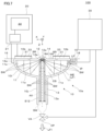
- FIG. 1 is a sectional view illustrating the ultrasonic supply device of the first embodiment.
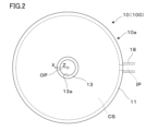
- FIG. 2 is a bottom view illustrating a waveguide in the ultrasonic supply device.
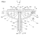
- FIG. 3 is a cross-sectional view illustrating the ultrasonic supply device of the second embodiment.
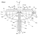
- FIG. 4 is a cross-sectional view illustrating the ultrasonic supply device of the third embodiment.
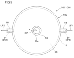
- FIG. 5 is a bottom view illustrating the ultrasonic supply device of the fourth embodiment.
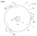
- FIG. 6 is a diagram illustrating a modification of the ultrasonic supply device of FIG. 5.
- FIG. 7 is a cross-sectional view illustrating the ultrasonic supply device of the fifth embodiment.
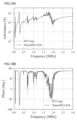
- FIGS. 8A to 8C are diagrams illustrating evaluations based on differences in media within the cavity of the ultrasonic vibration device.
- FIGS. 9A and 9B are diagrams illustrating the distribution of vibration velocity or displacement during resonance of the ultrasonic supply device.
- FIGS. 10A and 10B are diagrams illustrating evaluation of the ultrasonic supply device and the ultrasonic source of the example.
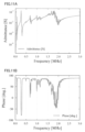
- FIG. 11A is a diagram illustrating the operating efficiency of the ultrasonic supply device of the example
- FIG. 11B is a diagram illustrating the resonance efficiency of the ultrasonic supply device of the example.
- FIG. 12 is a diagram illustrating the sound pressure of the ultrasonic supply device of the example.
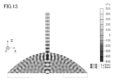
- FIG. 13 is a diagram illustrating the sound pressure distribution during resonance of the ultrasonic supply device of the example.
- an ultrasonic supply device 100 of the first embodiment includes an ultrasonic vibration device 10, a drive device 20, and a fluid supply device 30.
- the ultrasonic vibration device 10 includes a waveguide 10a that accommodates a fluid LF and applies ultrasonic SW to the fluid LF, and an ultrasonic source 10b that supplies the ultrasonic SW to the waveguide 10a.
- the waveguide 10a has an outer shape similar to a funnel, and includes a disk-shaped base 10i and a thin rod 10j having a hollow axis.
- the waveguide 10a includes a first reflecting member 11, a second reflecting member 12, a cylindrical member 13, a proximal member 14, and a flange 15.
- the first reflecting member 11, the second reflecting member 12, the base end member 14, etc. constitute a base portion 10i in appearance, and the cylindrical member 13 constitutes a thin rod 10j.
- the waveguide 10a is made of a metal material such as stainless steel (SUS), Hastelloy (registered trademark), fused silica, alumina, or the like.
- the first reflecting member 11 is formed of a thin plate obtained by cutting out a part of a dome in an annular shape.
- the first reflecting member 11 has a first reflecting surface 11a that is arranged coaxially with the annular ultrasonic radiation surface SR to reflect and focus the ultrasonic waves SW from the ultrasonic radiation surface SR toward the region RA.
- the second reflective member 12 is connected to the central portion of the proximal member 14 .
- the second reflecting member 12 has a second reflecting surface 12a that is disposed coaxially with the first reflecting surface 11a and reflects and collimates the ultrasonic wave SW reflected by the first reflecting surface 11a forward.
- the cylindrical member 13 is connected to the central portion of the first reflective member 11 and extends forward.
- the cylindrical member 13 has a cylindrical inner surface 13a, is arranged coaxially with the first reflecting surface 11a, and allows the ultrasonic wave SW reflected by the second reflecting surface 12a to pass therethrough.
- the base member 14 is disposed near the front of the ultrasound emission surface SR, and connects the outer edge 11e of the first reflecting member 11 and the outer edge 12e of the second reflecting member 12 to form a cavity CS.
- the proximal member 14 has a cylindrical portion 14a connected to the outer edge 11e of the first reflecting member 11 at the distal end, and a cylindrical portion 14a connected to the proximal end of the cylindrical portion 14a at the outer periphery and to the outer edge 12e of the second reflecting member 12 at the inner periphery.
- the flange 15 is provided to fix the ultrasonic vibration device 10 to a support or stage (not shown).
- the first reflecting member 11, the second reflecting member 12, the cylindrical member 13, and the base end member 14 form a cavity CS as an acoustic space.
- the first reflecting member 11, the second reflecting member 12, the cylindrical member 13, and the proximal member 14 need only have a thickness that maintains the shape of the waveguide 10a.
- the first reflecting member 11, the second reflecting member 12, the cylindrical member 13, and the proximal member 14 can be formed individually and then joined together.
- methods for joining the first reflecting member 11, the second reflecting member 12, etc. methods such as welding and adhesion can be used.
- the first reflecting member 11 and the cylindrical member 13 can be formed as an integral member.
- the first reflective member 11 and the base end member 14 can be formed as an integral member.
- the first reflecting member 11, the cylindrical member 13, and the base end member 14 can be formed as an integral member.
- the outer edge 11e of the first reflecting member 11 or the cylindrical portion 14a of the base end member 14 is provided with an inlet IP for introducing the fluid LF into the cavity CS.
- the introduction port IP is provided at one location on the cylindrical portion 14a, which is the side surface of the base end member 14. Note that the arrangement and number of introduction ports IP can be changed as appropriate.
- the introduction port IP may be provided at the annular portion 14b of the proximal member 14 or the root of the cylindrical member 13, that is, at the connection portion between the cylindrical member 13 and the first reflecting member 11.
- the inlet IP is connected to a fluid supply device 30, which will be described later, via a connecting member 18.
- the fluid LF is supplied from the fluid supply device 30 at a substantially constant flow rate so that the cavity CS is always filled with the fluid LF.
- the fluid LF is any one of a liquid, a gas, a sol, a gel, a mixture thereof, and a solid therein.
- fine particles may be mixed with a liquid or gas as a solid.
- a fluid containing solids such as stone or plastic may be crushed by ultrasonic cavitation.
- An outlet OP is provided at the tip of the cylindrical member 13. By discharging the fluid LF from the outlet OP, it is possible to cause the fluid LF to generate strong ultrasonic waves while flowing the fluid LF. This makes it possible to achieve a powerful ultrasonic effect with a high flow rate, for example in semiconductor wafer cleaning.
- the outlet OP is open, and the fluid LF supplied from the fluid supply device 30 is discharged at a substantially constant flow rate.
- the flow rate or flow rate of the fluid LF discharged from the outlet OP may be such that a predetermined amount of the fluid LF is continuously discharged, or may be such that drops fall at regular intervals.
- the cavity CS is filled with fluid LF. That is, the inside of the cavity CS is filled with the fluid LF without any gaps.
- the cavity CS allows the sound waves to uniformly propagate through the fluid LF, which is the medium ME.
- the fluid LF introduced into the cavity CS may be one type or multiple types. For example, when air as a second fluid is introduced into a liquid as a first fluid, the air can be turned into nanobubbles due to the effect of powerful ultrasonic waves. Alternatively, the mixture may be introduced as the fluid LF.
- the first reflecting surface 11a of the first reflecting member 11 focuses the ultrasonic waves SW from the ultrasonic radiation surface SR onto a region RA corresponding to a focal point. Therefore, the first reflective surface 11a has a shape in which a concave curve is rotated backward, that is, in the -Z direction. That is, the first reflecting member 11 receives and reflects the ultrasonic waves SW from the ultrasonic emission surface SR on its concave surface, thereby converging them.
- the second reflecting surface 12a of the second reflecting member 12 transmits the ultrasonic wave SW that passes through the region RA and diverges into the space S12 formed in the cylindrical member 13.
- the second reflective surface 12a has a shape in which a concave curve is rotated forward, that is, in the +Z direction.
- the ultrasonic wave SW sent to the space S12 is close to a plane wave, and has substantially the same phase in the Z direction, which is the traveling direction.
- the first reflective surface 11a of the first reflective member 11 rotates a backward concave parabola around the central axis AX of the cylindrical member 13 in the axial section (specifically, the XZ plane) of the cylindrical member 13. It is a plane of symmetry.
- the second reflective surface 12a of the second reflective member 12 rotates around the central axis AX of the cylindrical member 13 by rotating a forward concave parabola in the axial section (specifically, the XZ plane) of the cylindrical member 13. It is a plane of symmetry.
- the ratio of the diameter of the thin rod 10j or the cylindrical member 13 to the diameter of the base 10i or the diameter of the first reflective member 11 should not exceed 1:2.
- the diameter of the thin rod 10j becomes relatively large, the propagation loss of ultrasonic waves becomes large. For example, if the outer diameter of the base 10i or the ultrasonic source 10b is 40 mm, the outer diameter of the thin rod 10j is about 20 mm at the maximum.
- the flange 15 for fixing the ultrasonic vibration device 10 to a support or a stage may be integrated with the main body including the first reflecting member 11 and the proximal member 14, but it may be manufactured separately from the main body and then joined. It may be something that is done.
- the ultrasonic vibration device 10 can also be fixed to a support body via the outer periphery of the cylindrical member 13 when the vibration on the outer circumferential side of the cylindrical member 13 is small.
- the periphery of the base 10i consisting of the first reflecting member 11 and the second reflecting member 12 can be housed in a cover that is ground-shielded.
- the ultrasonic source 10b is a thick annular member, and radiates plane wave-like ultrasonic waves SW forward from a front annular ultrasonic radiation surface SR. Since the ultrasonic radiation surface SR is annular, the shape of the ultrasonic radiation surface SR can correspond to the shape of the second reflection surface 12a of the second reflection member 12.
- the ultrasonic radiation surface SR is a surface substantially parallel to a cross section (specifically, an XY plane) perpendicular to the central axis AX.
- the ultrasonic wave SW passes through the annular portion 14b of the base end member 14, is guided into the cavity CS, and enters the first reflecting surface 11a of the first reflecting member 11.
- the ultrasonic source 10b is a piezoelectric element (PZT) in which an electrode 33 is formed on the rear surface of an annular plate-shaped piezoelectric ceramic 31.
- the piezoelectric ceramic 31 has discrete resonance frequency characteristics determined by the overall structure that enables the output of powerful ultrasonic waves SW, and resonance frequency characteristics determined by the thickness of the piezoelectric ceramic 31. The thinner the piezoelectric ceramic 31 is, the higher the fundamental frequency can be.
- the ultrasonic source 10b is bonded to the annular portion 14b of the proximal member 14 using, for example, an adhesive. Note that if the ultrasonic source 10b is made removable, it becomes possible to replace the ultrasonic source 10b.
- the ultrasonic supply device 100 can be operated appropriately to irradiate the target with ultrasonic waves SW of a desired intensity from the tip of the cylindrical member 13. Moreover, the temperature rise of the ultrasonic source 10b can be reduced due to the cooling effect of the fluid LF in the cavity CS.
- an adhesive is applied to the surface of the annular portion 14b at the base 10i, and the ultrasonic source 10b is pressed and cured. Annealing is performed in an oven while compressing and preloading the ring portion 14b.
- an epoxy resin was used as the adhesive
- the thickness of the adhesive upon curing was 2 to 50 ⁇ m
- the preload range was 4 to 80 kPa
- the annealing temperature was 100 to 200°C.
- the material and composition of the adhesive can be varied in various ways.
- the drive device 20 includes a power supply circuit 21 that supplies a sinusoidal drive signal of, for example, several tens of kHz to several MHz to the ultrasonic source 10b, and a control circuit 22 that controls the operating state of the power supply circuit 21.
- the fluid supply device 30 supplies the fluid LF from the inlet IP through the connection member 18 into the cavity CS of the waveguide 10a.
- the fluid supply device 30 controls the amount of fluid LF introduced into the cavity CS, the introduction speed, and the like.
- a fluid LF is supplied to the cavity CS of the waveguide 10a under the control of the fluid supply device 30.
- the power supply circuit 21 is operated under the control of the control circuit 22 to emit plane wave-shaped ultrasonic waves SW forward from the ultrasonic radiation surface SR of the ultrasonic source 10b.
- This ultrasonic wave SW passes through the annular portion 14b of the base end member 14, enters the cavity CS filled with the fluid LF, and enters the first reflecting surface 11a of the first reflecting member 11.
- the ultrasonic wave SW is reflected by the first reflecting surface 11a, and enters the area RA corresponding to the focal point while being focused.
- the ultrasonic wave SW that has passed through the region RA is incident on the second reflective surface 12a of the second reflective member 12.
- the ultrasonic wave SW is reflected by the second reflecting surface 12a and is emitted with high energy density into the narrow space S12 formed in the cylindrical member 13.
- the ultrasonic wave SW collected in the space S12 is guided while maintaining a state similar to a plane wave, and is radiated with high energy density in front of the cylindrical member 13 together with the fluid LF.
- the ultrasonic wave SW is transmitted to the liquid in the process of propagating inside the waveguide 10a, and as the liquid flows from the outlet OP, powerful ultrasonic waves are generated into the liquid. can be generated.
- the medium ME through which the ultrasonic wave SW propagates is the fluid LF having substantially no shear force
- the medium ME through which the ultrasonic wave SW propagates is the fluid LF having substantially no shear force
- loss caused by converting longitudinal waves into transverse waves on a reflective surface such as metal is reduced, and the longitudinal waves are reflected by the first and second reflecting members 11 and 12 as longitudinal waves.
- the focusing efficiency of the ultrasonic SW can be improved, and high sound pressure can be output.
- the sound speed of the fluid LF is slower than the sound speed of a solid such as metal, the wavelength at the same frequency becomes shorter. Therefore, by using the fluid LF as the medium ME, the vibration propagation is closer to a plane wave, and the propagation is as designed, so that the focusing effect of the ultrasonic wave SW is enhanced.
- the ultrasonic supply device of the second embodiment is a partially modified ultrasonic supply device of the first embodiment, and a description of common parts will be omitted.
- the second reflective surface 12a of the second reflective member 12 has a curved shape that is convex toward the front, that is, the +Z side.
- the second reflective surface 12a is a rotationally symmetrical surface formed by rotating a forwardly convex parabola around the central axis AX of the cylindrical member 13 in the axial section (specifically, the XZ plane) of the cylindrical member 13.
- the ultrasonic source 10b is a thick circular member, and radiates plane wave-shaped ultrasonic waves SW forward from the front ultrasonic radiation surface SR.
- the second reflecting surface 12a since the second reflecting surface 12a has a forwardly convex shape, even if the ultrasonic source 10b is circular or disk-shaped, it can be placed immediately after the annular portion 14b. Thereby, the shape of the ultrasonic source 10b is not limited, and manufacturing costs can be reduced. Further, when the second reflective surface 12a has a convex shape toward the front, cavitation is less likely to occur, so it is suitable for emulsifying chemicals and the like.
- the ultrasonic wave SW reflected by the first reflecting surface 11a of the first reflecting member 11 is reflected by the second reflecting surface 12a of the second reflecting member 12 while being focused, and is collimated.
- the first reflective surface 11a and the second reflective surface 12a are both paraboloids, are arranged concentrically, and have the same focal point.
- the ultrasonic supply device of the third embodiment is a partially modified ultrasonic supply device of the first embodiment, and a description of common parts will be omitted.
- the first reflecting member 11 is formed of a thin plate or a surface obtained by cutting out a part of a dome into an annular shape, and is arranged coaxially with the circular ultrasonic emission surface SR so that the first reflection member 11 is formed from a thin plate or a surface obtained by cutting out a part of the dome in an annular shape. It has a first reflecting surface 11a that reflects the ultrasonic waves SW and focuses them toward the annular area RA2.
- the second reflecting member 12 is formed of a thin plate or a surface obtained by cutting out a part of a toroidal surface or a one-lobed hyperboloid into an annular shape, and is arranged coaxially with the ultrasonic radiation surface SR, so that the ultrasonic waves reflected by the first reflecting surface 11a It has a second reflective surface 12a that reflects and collimates the SW forward.
- the first reflecting surface 11a of the first reflecting member 11 focuses the ultrasonic waves SW from the ultrasonic emission surface SR onto an annular region RA2 corresponding to a focal point. Therefore, the first reflective surface 11a has a shape in which a concave curve is rotated backward, that is, in the -Z direction.
- the second reflecting surface 12a of the second reflecting member 12 transmits the ultrasonic wave SW that passes through the annular region RA2 and diverges into the space S12. Therefore, the second reflective surface 12a has a shape in which a concave curve is rotated forward, that is, in the +Z direction.
- the ultrasonic wave SW sent to the space S12 is similar to a plane wave, and has substantially the same phase in the Z direction, which is the traveling direction.
- the first reflective surface 11a of the first reflective member 11 has an axis of symmetry TX that is a generatrix of a virtual reference cylindrical surface IT concentric with the cylindrical member 13 in the axial cross section (specifically, the XZ plane) of the cylindrical member 13. It is a rotationally symmetrical surface in which a backwardly concave parabola (outer parabola) extending outside the reference cylindrical surface IT is rotated around the central axis AX of the outer cylinder.
- the second reflective surface 12a of the second reflective member 12 extends forward toward the inside of the reference cylindrical surface IT with the generatrix of the reference cylindrical surface IT as the axis of symmetry TX in the axial section (specifically, the XZ plane) of the cylindrical member 13.
- a rotationally symmetrical surface such as the first reflective surface 11a and the second reflective surface 12a is also called a parabolic surface of rotation.
- the reference cylindrical surface IT does not need to match the inner cylindrical surface of the cylindrical member 13, and may be larger or smaller than the inner cylindrical surface of the cylindrical member 13. That is, the annular region RA2 corresponding to the focal point of the first reflective surface 11a may also be located inside or outside the cylindrical surface that is an extension of the cylindrical member 13.
- the introduction port IP includes a first introduction port IP1 that introduces the liquid LF1 into the cavity CS, and a second introduction port IP2 that introduces the gas LF2 into the cavity CS.
- the first introduction port IP1 and the second introduction port IP2 are arranged at symmetrical positions with respect to the cylindrical member 13.
- a gas LF2 as a second fluid such as air is introduced into the liquid LF1 as the first fluid introduced into the cavity CS, the air can be turned into nanobubbles due to the effect of powerful ultrasonic waves.
- fluid LF introduced into the first and second introduction ports IP1 and IP2 can be changed as appropriate. That is, gas may be introduced from the first introduction port IP1, or liquid may be introduced from the second introduction port IP2. Further, fluid may be introduced from both the first and second introduction ports IP1, IP2, or gas may be introduced from both the first and second introduction ports IP1, IP2.
- FIG. 6 shows a modification of the ultrasonic supply device 100 of FIG. 5, and is provided with three introduction ports IP.
- the first to third introduction ports IP1 to IP3 are equally arranged on the circumference of the side surface 11d of the first reflecting member 11.
- the first to third inlet ports IP1 to IP3 are arranged at an angle to the side surface 11d (that is, at an inclination of less than 90° with respect to a perpendicular state) so as to form a flow. Note that even when there is only one inlet IP, it can be arranged at an angle to the side surface 11d so as to form a flow.
- the flow may be a steady flow or a turbulent flow.
- the ultrasonic supply device of the fifth embodiment is a partial modification of the ultrasonic supply device of the first embodiment, and a description of common parts will be omitted.
- the outlet OP provided at the tip of the cylindrical member 13 has a valve VA.
- the valve VA opens the outlet OP by an opening operation controlled by the fluid supply device 30, and discharges the fluid LF in the cavity CS or the cylindrical member 13 to the outside. Further, the valve VA closes the outlet OP by a closing operation under the control of the fluid supply device 30, and prevents the fluid LF from being discharged from the cylindrical member 13.
- opening and closing the valve VA the discharge flow rate and timing of the fluid LF from the outlet OP can be controlled.
- connection between the cylindrical member 13 and the valve VA is thin, but it does not have to be thin.
- FIG. 8A is a diagram illustrating the operating efficiency of the ultrasonic supply device 100.
- the horizontal axis indicates the driving frequency of the output voltage of the ultrasonic source 10b
- the vertical axis indicates admittance (ease of current flow). It can be said that as the peak value of admittance increases at a certain frequency, the energy absorption efficiency increases.
- the dotted line indicates the case of the conventional ultrasonic supply device 100
- the solid line indicates the case of the reference ultrasonic supply device 100.
- the reference example has a larger amplitude as a whole, and it can be said that the ultrasonic energy can be injected efficiently.
- FIG. 8B is a diagram illustrating the resonance efficiency of the ultrasonic supply device 100.
- the horizontal axis indicates the driving frequency of the output voltage of the ultrasonic source 10b
- the vertical axis indicates the phase between the current and voltage. It can be said that the more the phase is reversed, the more resonance occurs.
- the dotted line indicates the case of the conventional ultrasonic supply device 100
- the solid line indicates the case of the reference ultrasonic supply device 100.
- FIG. 8C is a diagram illustrating the speed of the tip of the cylindrical member 13 or thin rod 10j of the ultrasonic supply device 100.
- the horizontal axis indicates the driving frequency of the output voltage of the ultrasonic source 10b
- the vertical axis indicates the vibration speed of the tip of the cylindrical member 13. The higher the speed of the cylindrical member 13 in the axial direction, the more efficiently the medium ME is vibrated.
- the dotted line indicates the case of the conventional ultrasonic supply device 100, and the solid line indicates the case of the reference ultrasonic supply device 100.
- the vibration speed is high as a whole, but there is no high peak value.
- the vibration speed is low overall, there are locally high peak values, and it is expected that vibration can be applied efficiently by tuning.
- the maximum peak was 1.3225 Hz and a vibration speed of 0.471 m/s was obtained.
- the maximum peak was 1.506 Hz and a vibration speed of 0.329 m/s was obtained. From the above, it can be seen that in the reference example, a vibration speed 1.43 times that of the conventional example can be obtained.
- FIGS. 9A and 9B are diagrams illustrating the distribution of vibration velocity or displacement during resonance of the ultrasonic supply device 100.
- FIG. 9A shows the case of the conventional ultrasonic supply device 100 (1.506 Hz resonance)
- FIG. 9B shows the case of the reference example of the ultrasonic supply device 100 (1.3225 Hz resonance).
- the vibration speed is higher at the center closer to the axis, and the vibration speed is lower at the periphery closer to the side.
- the vibration speed is uniform both at the center and around the periphery. If not only the center but also the periphery is evaluated, the evaluation of the ultrasonic supply device 100 of the reference example may be improved.
- the diameter of the cylindrical member 13 is 1 mm, and the length is 10 mm.
- the ultrasonic source 10b has an outer diameter of 20 mm, an inner diameter of 8 mm, and a thickness of 1.1 mm.
- FIG. 10A is a diagram illustrating the operating efficiency of the ultrasonic supply device 100.
- the horizontal axis shows the driving frequency of the output voltage of the ultrasonic source 10b
- the vertical axis shows the admittance.
- the dotted line shows the case of PZT alone
- the solid line shows the case of the ultrasonic supply device 100 of the embodiment.
- the peak amplitude width is slightly smaller in the example than in the conventional example. In other words, the Q value decreases slightly. Note that the higher the Q value, the less attenuation occurs.
- FIG. 10B is a diagram illustrating the resonance efficiency of the ultrasonic supply device 100.
- the horizontal axis shows the driving frequency of the output voltage of the ultrasonic source 10b
- the vertical axis shows the phase between the current and voltage.
- the dotted line shows the case of PZT alone
- the solid line shows the case of the ultrasonic supply device 100 of the embodiment.
- PZT alone has slightly more phase changes and inversions, but there is not much difference between the two.
- FIG. 11A is a diagram illustrating the operational efficiency of the ultrasonic supply device 100 of the example.
- the horizontal axis shows the driving frequency of the output voltage of the ultrasonic source 10b
- the vertical axis shows the admittance.
- FIG. 11B is a diagram illustrating the resonance efficiency of the ultrasonic supply device 100 of the example.
- the horizontal axis indicates the driving frequency of the output voltage of the ultrasonic source 10b
- the vertical axis indicates the phase between the current and voltage.
- FIG. 12 is a diagram illustrating the sound pressure of the ultrasonic supply device 100 of the example. In FIG.
- the horizontal axis shows the driving frequency of the output voltage of the ultrasonic source 10b
- the vertical axis shows the sound pressure.
- the sound pressure is at the center point of the tip of the cylindrical member 13, and it is assumed that the ultrasonic supply device 100 is driven underwater.
- the boundary condition, that is, the material of the waveguide 10a is stainless steel (SUS304).
- FIG. 13 is a diagram illustrating the sound pressure distribution during resonance of the ultrasonic supply device 100 of the example.
- FIG. 13 shows the sound pressure distribution at 1.7835Hz resonance.
- the maximum value is 2 MPa and the minimum value is -4 MPa.
- the amplitude of the sound pressure is reduced. Although the sound pressure is attenuated toward the tip of the cylindrical member 13, high sound pressure can be produced by shortening the cylindrical member 13. Note that in order to prevent sound pressure from attenuating, a metal that is harder and heavier than SUS may be used.
- the cylindrical member 13 is not limited to having a constant diameter, and may have a tapered or widened shape.
- the first reflecting member 11, second reflecting member 12, cylindrical member 13, proximal member 14, etc. may be formed of different materials.
- the first reflecting member 11 and the second reflecting member 12 may have a difference in mutual acoustic impedance.
- the fluid LF may be sealed in the cavity CS of the waveguide 10a.
- the outlet OP is not provided, the cavity CS does not need to be provided in the cylindrical member 13.
- the first reflective surface 11a and the second reflective surface 12a do not necessarily have to have a geometrically strict shape.
- the first reflective surface 11a is not limited to the shape of a parabola rotated around the central axis AX, but also has the shape of a concave curve rotated backward, that is, to the -Z side. It may include a spherical surface, a free-form surface, etc., as long as it can focus plane wave-like ultrasonic waves.
- the second reflective surface 12a is not limited to having a shape in which a parabola is rotated around the central axis AX, but also has a shape in which a concave or convex curve is rotated toward the front, that is, the +Z side. includes a spherical surface, a free-form surface, etc., and any surface that converts the diverging ultrasonic waves into a plane wave may be used.
- the ultrasonic source 10b is not limited to one that uses piezoelectric ceramics 31, and may operate based on various principles.
- the piezoelectric ceramic 31 is not limited to a single ring, but may be divided into a plurality of pieces.
- the fluid LF introduced into the cavity CS is only gas, it can be used as an airborne ultrasound.
- the piezoelectric ceramic 31 is not used as it is as the ultrasound source 10b, but a unit for aerial ultrasound is provided.
- the annular portion 14b of the base member 14 may be omitted, and the surface of the piezoelectric ceramic 31 of the ultrasonic source 10b facing the waveguide 10a may be exposed. Further, a 1/4 ⁇ plate may be provided between the base end member 14 and the piezoelectric ceramic 31.
Landscapes
- Engineering & Computer Science (AREA)
- Physics & Mathematics (AREA)
- Acoustics & Sound (AREA)
- Signal Processing (AREA)
- Health & Medical Sciences (AREA)
- Otolaryngology (AREA)
- Mechanical Engineering (AREA)
- Apparatuses For Generation Of Mechanical Vibrations (AREA)
Abstract
超音波供給装置は、超音波放射面からの超音波を反射し集束させる第1反射面を有する第1反射部材と、第1反射面で反射された超音波を前方に反射する第2反射面を有する第2反射部材と、第1反射部材の中央から前方に延びる円筒状部材と、を備え、第1反射部材と第2反射部材とによって空洞が形成され、空洞内には、流体が満たされている。
Description
本発明は、超音波を局所的に供給する超音波供給装置に関し、特に先端から超音波を放出する細棒を有する超音波供給装置に関する。
超音波供給装置として、円環状の圧電セラミックス振動素子と、圧電セラミックス振動素子からの超音波を反射する集束用の第1放物面と、第1放物面からの超音波を反射する第2放物面とを備え、第1放物面の中央領域から前方に延びる細棒に平面波を送り込むものが公知となっている(非特許文献1)。
非特許文献1の超音波供給装置では、超音波が伝搬する媒体は金属であり、超音波が放物面で反射する際の金属と空気との界面において、入力した縦波振動は縦波と横波とに分離されて変換される。この超音波供給装置では、集束される超音波が縦波振動のみであるとして設計されているため、反射時に変換される横波は損失となり、超音波の集束効率が低下するおそれがある。
K. Chen, et al., "Double-parabolic-reLFectors acoustic waveguides for high-power medical ultrasound," Sci. Rep., vol. 9, 18493, 2019.
本発明は、上記背景技術に鑑みてなされたものであり、超音波の集束効率を向上させることができる超音波供給装置を提供することを目的とする。
一実施の形態によれば、超音波供給装置は、超音波放射面からの超音波を反射し集束させる第1反射面を有する第1反射部材と、第1反射面で反射された超音波を前方に反射する第2反射面を有する第2反射部材と、第1反射部材の中央から前方に延びる円筒状部材と、を備え、第1反射部材と第2反射部材とによって空洞が形成され、空洞内には、流体が満たされている。ここで、流体が満たされているとは、流体のみに限らず、流体に固体等が混合している場合も含む。
〔第1実施形態〕
以下、図面を参照しつつ、本発明に係る超音波供給装置の第1実施形態について説明する。
以下、図面を参照しつつ、本発明に係る超音波供給装置の第1実施形態について説明する。
図1及び図2を参照して、第1実施形態の超音波供給装置100は、超音波振動装置10と、駆動装置20と、流体供給装置30とを備える。超音波振動装置10は、流体LFを収納して流体LFに超音波SWを付与する導波器10aと、超音波SWを導波器10aに供給する超音波源10bとを備える。導波器10aは、ロートに類似する外形を有し、円盤状の基部10iと、軸心が中空の細棒10jとを有する。
超音波振動装置10のうち、導波器10aは、第1反射部材11と、第2反射部材12と、円筒状部材13と、基端部材14と、フランジ15とを備える。第1反射部材11、第2反射部材12、基端部材14等は、外観における基部10iを構成し、円筒状部材13は、細棒10jを構成する。導波器10aの材料は、音響インピーダンスが比較的高く、腐食しにくいものが望ましい。導波器10aは、例えばステンレススチール(SUS)、ハステロイ(登録商標)、溶融石英、アルミナ等の金属材料で形成される。
第1反射部材11は、ドームの一部を環状に切り出した薄板で形成されている。第1反射部材11は、円環状の超音波放射面SRと同軸に配置されて超音波放射面SRからの超音波SWを反射し領域RAに向かうように集束させる第1反射面11aを有する。第2反射部材12は、基端部材14の中央部に接続されている。第2反射部材12は、第1反射面11aと同軸に配置されて第1反射面11aで反射された超音波SWを前方に反射しコリメートする第2反射面12aを有する。円筒状部材13は、第1反射部材11の中央部に接続されて前方に延びる。円筒状部材13は、円筒内面13aを有し、第1反射面11aと同軸に配置されて第2反射面12aで反射された超音波SWを通過させる。基端部材14は、超音波放射面SRの前方の近傍に配置され、第1反射部材11の外縁11eと第2反射部材12の外縁12eとを接続して空洞CSを形成する。基端部材14は、先端において第1反射部材11の外縁11eに接続される円筒部14aと、外周において円筒部14aの基端に接続されるとともに内周において第2反射部材12の外縁12eに接続される円環部14bとを有する。この場合、円筒部14aによって、第1反射部材11と円環部14bとの間隔を調整し、空洞CSの広さを調整することができる。また、円環部14bによって、第2反射部材12を支持しつつ、空洞CSの内外を仕切ることができる。フランジ15は、超音波振動装置10を不図示の支持体やステージに固定するために設けられている。
上述の通り、第1反射部材11、第2反射部材12、円筒状部材13、及び基端部材14は、音響空間としての空洞CSを形成する。第1反射部材11、第2反射部材12、円筒状部材13、及び基端部材14は、導波器10aの形状を保つ程度の厚みを有していればよい。
第1反射部材11、第2反射部材12、円筒状部材13、及び基端部材14は、個別に形成して接合することができる。第1反射部材11、第2反射部材12等を接合する方法としては、溶接、接着等の手法を用いることができる。なお、第1反射部材11と円筒状部材13とは、一体の部材として形成することができる。また、第1反射部材11と基端部材14とは、一体の部材として形成することができる。また、第1反射部材11と円筒状部材13と基端部材14とは、一体の部材として形成することができる。
第1反射部材11の外縁11e又は基端部材14の円筒部14aには、空洞CS中に流体LFを導入する導入口IPが設けられている。図1等の例では、導入口IPは、基端部材14の側面である円筒部14aの一箇所に設けられている。なお、導入口IPの配置や数は適宜変更することができる。例えば、導入口IPは、基端部材14の円環部14bや円筒状部材13の根元、すなわち円筒状部材13と第1反射部材11との接続部分に設けてもよい。
導入口IPは、後述する流体供給装置30に接続部材18を介して接続されている。導入口IPでは、空洞CS内を常に流体LFで満たすように略一定の流速で流体LFが流体供給装置30から供給されている。流体LFは、液体、気体、ゾル、ゲル、これらの混合物、及びこれらに固体を含むもののいずれかである。例えば、液体や気体に固体として微粒子等を混ぜてもよい。また、石やプラスチック等の固体を含む流体を超音波キャビテーションによって粉砕させてもよい。
円筒状部材13の先端には、導出口OPが設けられている。導出口OPから流体LFが吐出されることにより、流体LFを流しながら流体LFに強力超音波を生成させることができる。これにより、例えば半導体ウェハ洗浄において、流速をもった強力超音波効果を実現することができる。図1等の例では、導出口OPは、開放されており、流体供給装置30から供給された流体LFが略一定の流速で吐出される。導出口OPから吐出される流体LFの流速又は流量は、所定量の流体LFが連続的に吐出する程度でもよいし又は滴が一定間隔で落ちる程度であってもよい。
空洞CS内には、流体LFが充填されている。すなわち、空洞CS内は、流体LFで隙間なく満たされている。空洞CSは、媒体MEである流体LFによって、音波を一様に伝搬させる。空洞CSに導入する流体LFは、1種類でも複数種類でもよい。例えば第1の流体としての液体中に第2の流体としての空気を導入すると、強力超音波の効果により、空気をナノバブル化させることができる。また、流体LFとして混合物を導入してもよい。
第1反射部材11の第1反射面11aは、超音波放射面SRからの超音波SWを焦点に相当する領域RAに集束させる。このため、第1反射面11aは、後方すなわち-Z方向に凹の曲線を回転させた形状を有する。つまり、第1反射部材11は、超音波放射面SRからの超音波SWを凹面で受けて反射することによって集束させる。第2反射部材12の第2反射面12aは、領域RAを通過して発散する超音波SWを円筒状部材13に形成された空間S12に送出する。このため、第2反射面12aは、前方すなわち+Z方向に凹の曲線を回転させた形状を有する。空間S12に送出される超音波SWは、平面波に近いものであり、進行方向であるZ方向に関して位相が略揃ったものとなっている。
第1反射部材11の第1反射面11aは、円筒状部材13の軸断面(具体的にはXZ面)において後方に凹の放物線を円筒状部材13の中心軸AXの周りに回転させた回転対称面である。第2反射部材12の第2反射面12aは、円筒状部材13の軸断面(具体的にはXZ面)において前方に凹の放物線を円筒状部材13の中心軸AXの周りに回転させた回転対称面である。
細棒10j又は円筒状部材13の直径の、基部10iの直径又は第1反射部材11の直径に対する比は、1:2を超えないようにする。細棒10jの直径が相対的に大きくなると、超音波の伝搬ロスが大きくなる。例えば基部10i又は超音波源10bの外径が40mmとして、細棒10jの外径は最大でも20mm程度とする。
超音波振動装置10を支持体やステージに固定するためのフランジ15は、第1反射部材11や基端部材14を含む本体と一体であってもよいが、本体とは別に作製された後に接合されるものであってもよい。超音波振動装置10は、円筒状部材13の外周側面の振動が少ない場合、円筒状部材13の外周を介して支持体に固定することもできる。なお、超音波振動装置10の支持に際しては、第1反射部材11や第2反射部材12からなる基部10iの周囲をグランドシールドされたカバー内に収納することができる。
超音波源10bは、厚みを有する円環状の部材であり、前方の円環状の超音波放射面SRから平面波状の超音波SWを前方に放射する。超音波放射面SRが円環状であることにより、超音波放射面SRの形状を第2反射部材12の第2反射面12aの形状に対応するものとすることができる。超音波放射面SRは、中心軸AXに垂直な断面(具体的にはXY面)に略平行な面である。超音波SWは、基端部材14の円環部14bを通過して空洞CS内に導波され、第1反射部材11の第1反射面11aに入射する。
超音波源10bは、円環板状の圧電セラミックス31の後面に電極33を形成した圧電素子(PZT)である。圧電セラミックス31は、強力な超音波SWの出力を可能にする全体の構造から決まるとびとびの共振周波数特性と圧電セラミックス31の厚さから決まる共振周波数特性とを有する。圧電セラミックス31の厚みが薄くなるほど基本周波数を高めることができる。超音波源10bは、例えば接着材を用いて基端部材14の円環部14bに接着される。なお、超音波源10bを着脱可能とすれば、超音波源10bの交換が可能になる。
超音波源10bを組み込むことで、超音波供給装置100を適切に動作させ、円筒状部材13の先端から所望の強度の超音波SWを対象に照射することができる。また、空洞CS内の流体LFの冷却効果により、超音波源10bの温度上昇を軽減することができる。
超音波源10bを円環部14bに接着する際には、基部10iにおいて円環部14bの表面に接着材を塗布して超音波源10bを押し付けて硬化させ、さらに、超音波源10bを円環部14bに対して圧縮予圧しながらオーブンでアニールする。接着材として例えばエポキシ樹脂を用い、接着材を硬化させる際の厚みを2~50μmとし、予圧の範囲を4~80kPaとし、アニール温度は100~200℃とした。接着材の材料や配合は、様々に変更可能である。
駆動装置20は、超音波源10bに対して、例えば数10kHz~数MHzの正弦波状の駆動信号を供給する電源回路21と、電源回路21の動作状態を制御する制御回路22とを有する。
流体供給装置30は、接続部材18を介して導入口IPから導波器10aの空洞CS内に流体LFを供給する。流体供給装置30は、空洞CSへの流体LFの導入量、導入速度等を制御する。
実施形態の超音波供給装置100の動作について説明する。流体供給装置30の制御下で導波器10aの空洞CSには、流体LFが供給されている。制御回路22の制御下で電源回路21を動作させ、超音波源10bの超音波放射面SRから平面波状の超音波SWを前方に射出させる。この超音波SWは、基端部材14の円環部14bを通過して流体LFが満たされた空洞CSに入射し、第1反射部材11の第1反射面11aに入射する。超音波SWは、第1反射面11aで反射され、焦点に相当する領域RAに集束しつつ入射する。領域RAを通過した超音波SWは、第2反射部材12の第2反射面12aに入射する。超音波SWは、第2反射面12aで反射され、円筒状部材13に形成された狭い空間S12に高いエネルギー密度で射出される。空間S12に集められた超音波SWは、平面波に近い状態を保ちつつ導波され、円筒状部材13の前方に流体LFとともに高いエネルギー密度で放射される。具体的には、例えば半導体ウェハ洗浄において、導波器10a内に超音波SWが伝搬していく過程で液体に超音波SWが伝わり、導出口OPから液体を流しながら液体の中に強力超音波を生成させることができる。
以上で説明した第1実施形態の超音波供給装置100では、超音波SWが伝搬する媒体MEが実質的に剪断力を有さない流体LFであるため、空洞CS内において横波がほとんど存在せず、金属のように反射面で縦波が横波に変換される損失が軽減し、縦波は縦波として第1及び第2反射部材11,12で反射される。これにより、超音波SWの集束効率を向上させることができ、高い音圧を出力することができる。流体LFの音速は、金属等の固体の音速よりも遅いため、同一周波数における波長が短くなる。したがって、流体LFを媒体MEとすることにより、より平面波に近い振動伝搬となり、設計通りの伝搬となるため、超音波SWの集束効果が高くなる。
〔第2実施形態〕
以下、本発明の第2実施形態に係る超音波供給装置について説明する。なお、第2実施形態の超音波供給装置は、第1実施形態の超音波供給装置を部分的に変更したものであり、共通部分については説明を省略する。
以下、本発明の第2実施形態に係る超音波供給装置について説明する。なお、第2実施形態の超音波供給装置は、第1実施形態の超音波供給装置を部分的に変更したものであり、共通部分については説明を省略する。
図3に示すように、本実施形態において、第2反射部材12の第2反射面12aは、前方すなわち+Z側に凸の曲線を回転させた形状を有している。第2反射面12aは、円筒状部材13の軸断面(具体的にはXZ面)において前方に凸の放物線を円筒状部材13の中心軸AXの周りに回転させた回転対称面である。
超音波源10bは、厚みを有する円形状の部材であり、前方の超音波放射面SRから平面波状の超音波SWを前方に放射する。
本実施形態では、第2反射面12aが前方に凸形状を有することにより、超音波源10bが円形状又は円板状でも円環部14bの直後に配置することができる。これにより、超音波源10bの形状が制限されず、製造コストを低減することができる。また、第2反射面12aが前方に凸形状を有する場合、キャビテーションが生じにくくなるため、薬品等の乳化に向いている。
第1反射部材11の第1反射面11aで反射された超音波SWは、集束されつつ第2反射部材12の第2反射面12aによって反射され、コリメートされる。この場合、第1反射面11a及び第2反射面12aは、ともに放物面であり、同心に配置され、焦点が一致する。
〔第3実施形態〕
以下、本発明の第3実施形態に係る超音波供給装置について説明する。なお、第3実施形態の超音波供給装置は、第1実施形態の超音波供給装置を部分的に変更したものであり、共通部分については説明を省略する。
以下、本発明の第3実施形態に係る超音波供給装置について説明する。なお、第3実施形態の超音波供給装置は、第1実施形態の超音波供給装置を部分的に変更したものであり、共通部分については説明を省略する。
図4に示すように、第1反射部材11は、ドームの一部を環状に切り出した薄板又は面で形成され、円形状の超音波放射面SRと同軸に配置されて超音波放射面SRからの超音波SWを反射し環状領域RA2に向かうように集束させる第1反射面11aを有する。第2反射部材12は、トロイダル面又は一葉双曲面の一部を環状に切り出した薄板又は面で形成され、超音波放射面SRと同軸に配置されて第1反射面11aで反射された超音波SWを前方に反射しコリメートする第2反射面12aを有する。
第1反射部材11の第1反射面11aは、超音波放射面SRからの超音波SWを焦点に相当する環状領域RA2に集束させる。このため、第1反射面11aは、後方すなわち-Z方向に凹の曲線を回転させた形状を有する。第2反射部材12の第2反射面12aは、環状領域RA2を通過して発散する超音波SWを空間S12に送出する。このため、第2反射面12aは、前方すなわち+Z方向に凹の曲線を回転させた形状を有する。空間S12に送出される超音波SWは、平面波に近いものであり、進行方向であるZ方向に関して位相が略揃ったものとなっている。
第1反射部材11の第1反射面11aは、円筒状部材13の軸断面(具体的にはXZ面)において円筒状部材13と同心の仮想的な基準円筒面ITの母線を対称軸TXとし基準円筒面ITの外側に延びる後方に凹の放物線(外側の放物線)を外筒の中心軸AXの周りに回転させた回転対称面である。第2反射部材12の第2反射面12aは、円筒状部材13の軸断面(具体的にはXZ面)において基準円筒面ITの母線を対称軸TXとし基準円筒面ITの内側に延びる前方に凹の放物線(内側の放物線)を円筒状部材13の中心軸AXの周りに回転させた回転対称面である。ここで、基準円筒面ITよりも外側の放物線の焦点と、基準円筒面ITよりも内側の放物線の焦点とは、互いに一致しており、環状領域RA2上に配置される。第1反射面11aや第2反射面12aのような回転対称面を放物回転面とも呼ぶ。なお、基準円筒面ITは、円筒状部材13の内筒面と一致する必要はなく、円筒状部材13の内筒面より大きくなっても小さくなってもよい。つまり、第1反射面11aの焦点に対応する環状領域RA2も、円筒状部材13を延長した円筒面の内側にあっても外側にあってもよい。
〔第4実施形態〕
以下、本発明の第4実施形態に係る超音波供給装置について説明する。なお、第4実施形態の超音波供給装置は、第1実施形態の超音波供給装置を部分的に変更したものであり、共通部分については説明を省略する。
以下、本発明の第4実施形態に係る超音波供給装置について説明する。なお、第4実施形態の超音波供給装置は、第1実施形態の超音波供給装置を部分的に変更したものであり、共通部分については説明を省略する。
図5に示すように、導入口IPは、複数設けられる。具体的には、導入口IPは、空洞CSに液体LF1を導入する第1導入口IP1と、空洞CSに気体LF2を導入する第2導入口IP2とを有する。図示の例では、第1導入口IP1と第2導入口IP2とは、円筒状部材13に対して対称な位置に配置される。空洞CSに導入された第1の流体としての液体LF1中に空気等の第2の流体としての気体LF2を導入すると、強力超音波の効果により、空気をナノバブル化させることができる。
導入口IPを複数設けることにより、各導入口IPから導入した複数の流体LFを混合して超音波SWを作用させることができる。また、空洞CS内部で生成されるキャビテーションによって化学反応を促進させることができる。
なお、第1及び第2導入口IP1,IP2に導入される流体LFは適宜変更することができる。すなわち、第1導入口IP1から気体を導入してもよいし、第2導入口IP2から液体を導入してもよい。また、第1及び第2導入口IP1,IP2の両方から流体を導入してもよいし、第1及び第2導入口IP1,IP2の両方から気体を導入してもよい。
図6は、図5の超音波供給装置100の変形例であり、3つの導入口IPを設けている。図6に示す超音波供給装置100では、導入口IPは、第1反射部材11の側面11dの円周上において、第1~第3導入口IP1~IP3が均等に配置されている。第1~第3導入口IP1~IP3は、流れを形成するように側面11dに対して角度をつけて(つまり、直角な状態に対し90°未満の傾きで)配置される。なお、導入口IPが1つの場合でも、流れを形成するように側面11dに対して角度をつけて配置することができる。流れについては、定常的な流れであってもよいし、乱流が生じていてもよい。
〔第5実施形態〕
以下、本発明の第5実施形態に係る超音波供給装置について説明する。なお、第5実施形態の超音波供給装置は、第1実施形態の超音波供給装置を部分的に変更したものであり、共通部分については説明を省略する。
以下、本発明の第5実施形態に係る超音波供給装置について説明する。なお、第5実施形態の超音波供給装置は、第1実施形態の超音波供給装置を部分的に変更したものであり、共通部分については説明を省略する。
図7に示すように、本実施形態では、円筒状部材13の先端に設けた導出口OPにバルブVAを有する。バルブVAは、流体供給装置30の制御による開動作により、導出口OPを開放し、空洞CS又は円筒状部材13内の流体LFを外部に吐出させる。また、バルブVAは、流体供給装置30の制御による閉動作により、導出口OPを閉鎖し、円筒状部材13の流体LFを円筒状部材13から吐出させない。バルブVAの開閉動作により、導出口OPからの流体LFの吐出流量やタイミングを制御することができる。
図示の例では、円筒状部材13とバルブVAとの接続部が細くなっているが、細くなくてもよい。
〔シミュレーション1〕
以下、超音波供給装置100の空洞CS内の媒体の違いによる評価について説明する。従来例の超音波供給装置100は、第1反射面11a、第2反射面12a、円筒内面13a、及び超音波放射面SRに囲まれた空間がジュラルミンで満たされているとした。参考例の超音波供給装置100は、第1反射面11a、第2反射面12a、円筒内面13a、及び超音波放射面SRに囲まれた空間が液体状のジュラルミンで満たされているとした。液体状のジュラルミンは、ジュラルミンと同じ物性値を持つが横波を発生させないものとしている。
以下、超音波供給装置100の空洞CS内の媒体の違いによる評価について説明する。従来例の超音波供給装置100は、第1反射面11a、第2反射面12a、円筒内面13a、及び超音波放射面SRに囲まれた空間がジュラルミンで満たされているとした。参考例の超音波供給装置100は、第1反射面11a、第2反射面12a、円筒内面13a、及び超音波放射面SRに囲まれた空間が液体状のジュラルミンで満たされているとした。液体状のジュラルミンは、ジュラルミンと同じ物性値を持つが横波を発生させないものとしている。
図8Aは、超音波供給装置100の動作効率について説明する図である。図8Aにおいて、横軸は超音波源10bの出力電圧の駆動周波数を示し、縦軸はアドミタンス(電流の流れやすさ)を示す。ある周波数においてアドミタンスのピーク値が上がるとエネルギーの吸収効率が上がるといえる。点線は従来例の超音波供給装置100の場合を示し、実線は参考例の超音波供給装置100の場合を示す。
図8Aに示すように、参考例の方が全体として振幅が大きく、超音波エネルギーを効率よく注入できているといえる。
図8Bは、超音波供給装置100の共振効率について説明する図である。図8Bにおいて、横軸は超音波源10bの出力電圧の駆動周波数を示し、縦軸は電流と電圧の間の位相を示す。位相が反転するほど共振が生じているといえる。点線は従来例の超音波供給装置100の場合を示し、実線は参考例の超音波供給装置100の場合を示す。
図8Bにおいて、従来例は、位相の変化や反転が少なく、共振があまり生じていない。参考例は、位相の変化や反転が大きく、共振が十分に生じている。
図8Cは、超音波供給装置100の円筒状部材13又は細棒10jの先端の速度について説明する図である。図8Cにおいて、横軸は超音波源10bの出力電圧の駆動周波数を示し、縦軸は円筒状部材13先端の振動速度を示す。円筒状部材13の軸方向の速度が大きいほど、媒体MEに効率よく振動を与えていることになる。点線は従来例の超音波供給装置100の場合を示し、実線は参考例の超音波供給装置100の場合を示す。
図8Cに示すように、従来例は、全体としては振動速度が大きいが、高いピーク値が存在ない。参考例は、全体としては振動速度が小さいが、局所的に高いピーク値が存在し、チューニングにより効率的に振動を与えうることが期待される。参考例では最大ピークは1.3225Hzで0.471m/sの振動速度が得られた。従来例では最大ピークは1.506Hzで0.329m/sの振動速度が得られた。以上のことから、参考例では、従来例の1.43倍の振動速度が得られることがわかる。
図9A及び9Bは、超音波供給装置100の共振時の振動速度又は変位の分布を説明する図である。図9Aは、従来例の超音波供給装置100の場合(1.506Hz共振)を示し、図9Bは、参考例の超音波供給装置100の場合(1.3225Hz共振)を示す。
円筒状部材13(上部の細いロッド状の部分)に着目すると、従来例の場合、軸に近い中心ほど振動速度が大きく、側面に近い周辺で振動速度が低下している。参考例の超音波供給装置100の場合、中心でも周辺でも振動速度が均一である。中心だけでなく周辺も併せて評価すると、参考例の超音波供給装置100の評価が高まる可能性がある。
〔シミュレーション2〕
以下、実施例の超音波供給装置100、及び超音波源(PZT単体)10bの評価について説明する。従来例は、超音波源(PZT単体)10bで正面方向の液体に超音波SWを供給している。実施例は、第1反射面11a、第2反射面12a、円筒内面13a、及び超音波放射面SRに囲まれた空間が水で満たされ、その外側にSUS304が存在するとした。第1反射部材11の第1反射面11aの形状はz=-r2/20+5で表され、第2反射部材12の第2反射面12aの形状は、z=r2-0.25で表される。円筒状部材13の直径は1mmであり、長さは10mmである。超音波源10bは、外径が20mmであり、内径が8mmであり、厚みが1.1mmである。シミュレーション2では、シミュレーションの計算負担を減らすため、実際の導波器10aの外径の半分の大きさ(r=20mm)を想定して計算している。
以下、実施例の超音波供給装置100、及び超音波源(PZT単体)10bの評価について説明する。従来例は、超音波源(PZT単体)10bで正面方向の液体に超音波SWを供給している。実施例は、第1反射面11a、第2反射面12a、円筒内面13a、及び超音波放射面SRに囲まれた空間が水で満たされ、その外側にSUS304が存在するとした。第1反射部材11の第1反射面11aの形状はz=-r2/20+5で表され、第2反射部材12の第2反射面12aの形状は、z=r2-0.25で表される。円筒状部材13の直径は1mmであり、長さは10mmである。超音波源10bは、外径が20mmであり、内径が8mmであり、厚みが1.1mmである。シミュレーション2では、シミュレーションの計算負担を減らすため、実際の導波器10aの外径の半分の大きさ(r=20mm)を想定して計算している。
図10Aは、超音波供給装置100の動作効率を説明する図である。図10Aにおいて、横軸は超音波源10bの出力電圧の駆動周波数を示し、縦軸はアドミタンスを示す。点線はPZT単体の場合を示し、実線は実施例の超音波供給装置100の場合を示す。
図10Aに示すように、従来例よりも実施例の方が、ピークの振幅幅が若干小さくなっている。つまり、Q値が若干下がる。なお、Q値が高いほど減衰しない。
図10Bは、超音波供給装置100の共振効率を説明する図である。図10Bにおいて、横軸は超音波源10bの出力電圧の駆動周波数を示し、縦軸は電流と電圧の間の位相を示す。点線はPZT単体の場合を示し、実線は実施例の超音波供給装置100の場合を示す。
図10Bに示すように、PZT単体の方が位相の変化や反転が若干多いが、両者の差はあまりない。
図11Aは、実施例の超音波供給装置100の動作効率を説明する図である。図11Aにおいて、横軸は超音波源10bの出力電圧の駆動周波数を示し、縦軸はアドミタンスを示す。図11Bは、実施例の超音波供給装置100の共振効率を説明する図である。図11Bにおいて、横軸は超音波源10bの出力電圧の駆動周波数を示し、縦軸は電流と電圧の間の位相を示す。図12は、実施例の超音波供給装置100の音圧を説明する図である。図12において、横軸は超音波源10bの出力電圧の駆動周波数を示し、縦軸は音圧を示す。音圧は、円筒状部材13先端の中心点におけるものであり、超音波供給装置100の水中での駆動を想定している。境界条件、すなわち、導波器10aの材質はステンレススチール(SUS304)としている。
図12に示すように、0.7MHz、1.7MHz辺りにピークがある。特に1.7835MHzに214kPaのピークが顕著である。
図13は、実施例の超音波供給装置100の共振時の音圧分布を説明する図である。図13は、1.7835Hz共振における音圧分布を示す。最大値は2MPaで、最小値は-4MPaとしている。
図13に示すように、円筒状部材13では、音圧の振れ幅が減少している。円筒状部材13の先端に向けて音圧が減衰しているが、円筒状部材13を短くすれば高い音圧を出すことができる。なお、音圧の減衰を防ぐため、SUSよりも硬く重い金属を用いてもよい。
この発明は、上記の実施形態に限られるものではなく、その要旨を逸脱しない範囲において種々の態様で実施することが可能である。
例えば、円筒状部材13は、一定の直径を有するものに限らず、先細り又は先広がりの形状とすることができる。
第1反射部材11、第2反射部材12、円筒状部材13、基端部材14等は、異なる材質で形成されてもよい。第1反射部材11及び第2反射部材12は、相互の音響インピーダンスに差があってもよい。
導入口IP又は導出口OPを設けなくてもよい。すなわち、導波器10aの空洞CS内に流体LFを封入してもよい。また、導出口OPを設けない場合、円筒状部材13に空洞CSを設けなくてもよい。
第1反射面11aや第2反射面12aは、必ずしも幾何的に厳密な形状を有するものでなくてもよい。つまり、第1反射面11aは、放物線を中心軸AXの周りに回転させた形状を有するものに限らず、後方すなわち-Z側に凹の曲線を回転させた形状を有し、具体的には球面、自由曲面等を含むものであり、平面波状の超音波を集束させるものであればよい。また、第2反射面12aは、放物線を中心軸AXの周りに回転させた形状を有するものに限らず、前方すなわち+Z側に凹又は凸の曲線を回転させた形状を有し、具体的には球面、自由曲面等を含むものであり、発散する超音波を平面波状にするものであればよい。
超音波源10bは、圧電セラミックス31を用いるものに限らず、様々な原理で動作するものとすることができる。圧電セラミックス31は、一体の円環に限らず、複数に分割されたものであってもよい。
空洞CSに導入する流体LFを気体のみとした場合、空中超音波として利用できる。この場合、超音波源10bとして圧電セラミックス31をそのまま用いず、空中超音波用のユニットを設ける。
基端部材14のうち円環部14bを省略し、超音波源10bの圧電セラミックス31が導波器10aと対面する面が露出していてもよい。また、基端部材14と圧電セラミックス31との間に1/4λ板を設けてもよい。
本発明は上記各実施の形態に限定されず、本発明の技術思想の範囲内において、各実施の形態は適宜変形又は変更されうることは明らかである。各実施の形態の技術は、技術的矛盾の発生しない限り、他の実施の形態で用いることが可能である。
なお、この出願は、2022年8月30日に出願された日本国特許出願2022-136568号を基礎とする優先権を主張し、その開示のすべてを引用によりここに組み込む。
Claims (15)
- 超音波放射面からの超音波を反射し集束させる第1反射面を有する第1反射部材と、
前記第1反射面で反射された前記超音波を前方に反射する第2反射面を有する第2反射部材と、
前記第1反射部材の中央から前方に延びる円筒状部材と、
を備え、
前記第1反射部材と前記第2反射部材とによって空洞が形成され、
前記空洞内には、流体が満たされている超音波供給装置。 - 前記空洞は、前記第1反射部材と前記第2反射部材と前記円筒状部材とによって形成される、請求項1に記載の超音波供給装置。
- 前記流体は、液体、気体、ゾル、ゲル、これらの混合物、及びこれらに固体を含むもののいずれかである、請求項1及び2のいずれか一項に記載の超音波供給装置。
- 前記空洞に前記流体を導入する導入口が設けられ、前記円筒状部材に導出口が設けられている、請求項2及び3のいずれか一項に記載の超音波供給装置。
- 前記第1反射部材と前記第2反射部材とを繋ぐ基端部材を備え、
前記導入口は、前記基端部材の側面に設けられる、請求項4に記載の超音波供給装置。 - 前記空洞は、回転対称な形状を有し、
前記導入口は、流れを形成するように前記側面に対して角度をつけて配置される、請求項5に記載の超音波供給装置。 - 前記導入口は、複数設けられる、請求項1~6のいずれか一項に記載の超音波供給装置。
- 前記導入口は、前記空洞に第1の流体を導入する第1導入口と、前記空洞に第2の流体を導入する第2導入口とを有する、請求項7に記載の超音波供給装置。
- 前記第1反射面は、後方に凹の曲線を回転させた形状を有する、請求項1~8のいずれか一項に記載の超音波供給装置。
- 前記第1反射面は、放物面を有する、請求項9に記載の超音波供給装置。
- 前記第2反射面は、前方に凹又は凸の曲線を回転させた形状を有する、請求項9及び10のいずれか一項に記載の超音波供給装置。
- 前記第2反射面は、放物面を有する、請求項11に記載の超音波供給装置。
- 前記超音波放射面は、円環状である、請求項9~12のいずれか一項に記載の超音波供給装置。
- 前記超音波放射面から超音波を前方に放射する超音波源をさらに備える、請求項1~13のいずれか一項に記載の超音波供給装置。
- 前記超音波放射面から超音波を前方に放射する超音波源をさらに備え、
前記第2反射面は、前方に凸の曲線を回転させた形状を有し、
前記超音波源は、円形状である、請求項9に記載の超音波供給装置。
Priority Applications (1)
| Application Number | Priority Date | Filing Date | Title |
|---|---|---|---|
| JP2024544295A JPWO2024048596A1 (ja) | 2022-08-30 | 2023-08-29 |
Applications Claiming Priority (2)
| Application Number | Priority Date | Filing Date | Title |
|---|---|---|---|
| JP2022136568 | 2022-08-30 | ||
| JP2022-136568 | 2022-08-30 |
Publications (1)
| Publication Number | Publication Date |
|---|---|
| WO2024048596A1 true WO2024048596A1 (ja) | 2024-03-07 |
Family
ID=90099537
Family Applications (1)
| Application Number | Title | Priority Date | Filing Date |
|---|---|---|---|
| PCT/JP2023/031266 Ceased WO2024048596A1 (ja) | 2022-08-30 | 2023-08-29 | 超音波供給装置 |
Country Status (2)
| Country | Link |
|---|---|
| JP (1) | JPWO2024048596A1 (ja) |
| WO (1) | WO2024048596A1 (ja) |
Citations (1)
| Publication number | Priority date | Publication date | Assignee | Title |
|---|---|---|---|---|
| JP2021090181A (ja) * | 2019-12-06 | 2021-06-10 | 日本特殊陶業株式会社 | 超音波発生装置 |
-
2023
- 2023-08-29 WO PCT/JP2023/031266 patent/WO2024048596A1/ja not_active Ceased
- 2023-08-29 JP JP2024544295A patent/JPWO2024048596A1/ja active Pending
Patent Citations (1)
| Publication number | Priority date | Publication date | Assignee | Title |
|---|---|---|---|---|
| JP2021090181A (ja) * | 2019-12-06 | 2021-06-10 | 日本特殊陶業株式会社 | 超音波発生装置 |
Non-Patent Citations (1)
| Title |
|---|
| YAMADA, KYOHEI ET AL. : "Fundamental Study of Tube-Type Double-Parabolic-Reflectors Ultrasonic Transducer", IEICE TECHNICAL REPORT, IEICE, JP, vol. 121, no. 67 (US2021-9), 18 June 2021 (2021-06-18), JP , pages 6 - 11, XP009547618, ISSN: 2432-6380 * |
Also Published As
| Publication number | Publication date |
|---|---|
| JPWO2024048596A1 (ja) | 2024-03-07 |
Similar Documents
| Publication | Publication Date | Title |
|---|---|---|
| JP7752431B2 (ja) | 超音波供給装置 | |
| US5485828A (en) | Portable device for micropulverization generated by ultrasound waves | |
| US6749406B2 (en) | Ultrasonic pump with non-planar transducer for generating focused longitudinal waves and pumping methods | |
| EP1470546B1 (en) | Method and apparatus for focussing ultrasonic energy | |
| AU2002322636B2 (en) | Apparatus for focussing ultrasonic acoustical energy within a liquid stream | |
| EP2064994B1 (en) | Resonance ultrasonic transducer | |
| US9011698B2 (en) | Method and devices for sonicating liquids with low-frequency high energy ultrasound | |
| JP7612151B2 (ja) | 流路内蔵型超音波振動子 | |
| TWI413553B (zh) | 產生超音波振動的裝置 | |
| JP2647352B2 (ja) | 半導体ウエハー洗浄装置 | |
| US4757227A (en) | Transducer for producing sound of very high intensity | |
| JPS6451162A (en) | Piezoelectric exciting type resonator | |
| JPH0197995A (ja) | 弾性波の負半波を抑制又は減衰させる音響フィルタ及び該フィルタを有する弾性波発振器 | |
| US8343421B2 (en) | Method and system for enhanced high intensity acoustic waves application | |
| Al-Jumaily et al. | On the development of focused ultrasound liquid atomizers | |
| CN100354925C (zh) | 非柱面声波装置 | |
| US7712680B2 (en) | Ultrasonic atomizing nozzle and method | |
| JP2014171928A (ja) | 超音波反応装置 | |
| JP2012095999A (ja) | 流体噴射装置及び医療機器 | |
| Wang et al. | 2E1-2 Multi-frequency ultrasonic atomization of circular plate by single parabolic reflector transducer | |
| Gallego-Juárez | High power ultrasonic transducers for use in gases and interphases | |
| JP2005186030A (ja) | 超音波放射体、超音波放射ユニット、超音波放射装置、及びこれを用いた超音波処理装置 | |
| JPH1190330A (ja) | 超音波放射装置 | |
| TW202502053A (zh) | 超音波產生裝置 | |
| JP4353518B2 (ja) | 超音波放射体、超音波放射装置、及びこれを用いた超音波処理装置 |
Legal Events
| Date | Code | Title | Description |
|---|---|---|---|
| 121 | Ep: the epo has been informed by wipo that ep was designated in this application |
Ref document number: 23860358 Country of ref document: EP Kind code of ref document: A1 |
|
| WWE | Wipo information: entry into national phase |
Ref document number: 2024544295 Country of ref document: JP |
|
| NENP | Non-entry into the national phase |
Ref country code: DE |
|
| 122 | Ep: pct application non-entry in european phase |
Ref document number: 23860358 Country of ref document: EP Kind code of ref document: A1 |