WO2024047876A1 - 映像伝送システム、映像伝送制御方法およびプログラム - Google Patents
映像伝送システム、映像伝送制御方法およびプログラム Download PDFInfo
- Publication number
- WO2024047876A1 WO2024047876A1 PCT/JP2022/033177 JP2022033177W WO2024047876A1 WO 2024047876 A1 WO2024047876 A1 WO 2024047876A1 JP 2022033177 W JP2022033177 W JP 2022033177W WO 2024047876 A1 WO2024047876 A1 WO 2024047876A1
- Authority
- WO
- WIPO (PCT)
- Prior art keywords
- video
- line
- video data
- information
- processing unit
- Prior art date
- Legal status (The legal status is an assumption and is not a legal conclusion. Google has not performed a legal analysis and makes no representation as to the accuracy of the status listed.)
- Ceased
Links
Images


Classifications
-
- H—ELECTRICITY
- H04—ELECTRIC COMMUNICATION TECHNIQUE
- H04N—PICTORIAL COMMUNICATION, e.g. TELEVISION
- H04N21/00—Selective content distribution, e.g. interactive television or video on demand [VOD]
- H04N21/20—Servers specifically adapted for the distribution of content, e.g. VOD servers; Operations thereof
- H04N21/23—Processing of content or additional data; Elementary server operations; Server middleware
- H04N21/24—Monitoring of processes or resources, e.g. monitoring of server load, available bandwidth, upstream requests
Definitions
- One aspect of the present invention relates to a video transmission system used, for example, to transmit relay video of an event, and a video transmission control method and program used in this system.
- Patent Document 1 a system described in Patent Document 1 is known as a system that transmits relay video of an event such as sports or entertainment from a transmitting side to a receiving side via a network.
- This system encodes multimedia content including video and sound using an encoder at the transmitting site, transmits it to the receiving site via a network, and decodes the transmitted multimedia content using a decoder at the receiving site. playback and output.
- the receiving site can view the relay video transmitted from the transmitting site in real time.
- This invention was made in view of the above circumstances, and aims to provide a technology that improves real-time performance by reducing video processing delays when relay video is distributed and transmitted over multiple lines. It is.
- one aspect of the video transmission system or the video transmission control method according to the present invention is a video transmission system that distributes and transmits video data from a sending device to a receiving device using a plurality of lines.
- the receiving device generates line state determination information for each of the plurality of lines, including at least the line identification information and information representing the amount of delay, and transmits the generated line state determination information to the transmitting device.
- the transmitting side device determines the transmission priority of the video data for each frame area of the video data, and determines the transmission priority of the video data for each frame region of the video data, and determines the transmission priority of the plurality of circuits based on information representing the delay amount included in the line state determination information.
- the quality is determined, and based on the transmission priority determination result and the line quality determination result, the video data is sequentially selected from the video of the area with the high transmission priority, and the video of the selected area is
- the circuits are allocated to a plurality of lines in order of line quality.
- the transmitting side device when transmitting video data, transmits the video data based on the delay amount of each of the plurality of lines and the transmission priority for each area within the frame determined by the type of video data. Then, pixel groups in areas with high transmission priority are sequentially allocated and transmitted in order from the line with the least amount of delay and the best line quality. Therefore, the receiving device receives video data in the order of pixel groups in areas with high transmission priority and with low delay. As a result, video data can be played back with less delay, and the real-time nature of relay video can be improved.
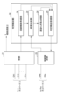
- FIG. 1 is a block diagram showing the configuration of a video transmission system according to an embodiment of the present invention.
- FIG. 2 is a block diagram illustrating an example of the functional configuration of a determination information collection unit provided in the receiving side device of the video transmission system illustrated in FIG. 1.
- FIG. 3 is a block diagram illustrating an example of the functional configuration of a priority processing determining section provided in the transmitting side device of the video transmission system illustrated in FIG. 1.
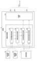
- FIG. 4 is a block diagram illustrating an example of the functional configuration of a line allocation control section provided in the transmitting side device of the video transmission system illustrated in FIG. 1.
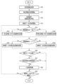
- FIG. 5 is a flowchart showing an example of the processing procedure and processing contents of the line allocation control section shown in FIG.
- FIG. 1 is a block diagram showing the configuration of a video transmission system according to an embodiment of the present invention.
- the video transmission system of one embodiment connects, via a network 3, a transmitting device 1 installed, for example, at an event venue, and a receiving device 2, installed, for example, in a viewer's home.
- the network 3 includes a plurality of lines CH1 to CHn used to transmit video data from the sending device 1 to the receiving device 2.
- These lines CH1 to CHn include a plurality of types of physical lines, such as optical lines and wireless lines, with different delay amounts and transmission bands.
- the receiving device 2 includes a receiving section 21, a video processing section 22, and a display section 23, and in addition, a determination information collecting section 24 and a control information transmitting section 25 as new functions according to the present invention. We are prepared.
- the receiving unit 21, the video processing unit 22, and the display unit 23 sequentially receive packets of video data transmitted from the transmitting device 1 selectively via the lines CH1 to CHn, and sequentially decode the received packets.
- the original video data is played back, and the played back video data is displayed on the display section 23. Note that although only video data will be explained in this example, audio data and additional data transmitted together with video data are similarly reproduced and output.
- the determination information collection unit 24 collects information necessary to determine the delay amount and transmission band for each of the lines CH1 to CHn, and generates line state determination information representing the result of determination of the state of the lines CH1 to CHn. generate.
- the determination information collection unit 24 includes, for example, a control unit using a hardware processor such as a central processing unit (CPU), a storage unit having a program storage unit and a data storage unit, and an input/output interface (hereinafter referred to as an interface). (abbreviated as I/F).
- a hardware processor such as a central processing unit (CPU), a storage unit having a program storage unit and a data storage unit, and an input/output interface (hereinafter referred to as an interface). (abbreviated as I/F).
- FIG. 2 is a block diagram illustrating an example of the processing functions included in the determination information collection unit 24.
- the determination information collection section 24 includes a line information acquisition processing section 241, a delay calculation processing section 242, a delay fluctuation calculation processing section 243, and a determination information transmission processing section 244 as its processing functions.
- the line information acquisition processing unit 241 receives from the receiving unit 21 information for identifying the lines CH1 to CHn (hereinafter referred to as line ID) and reception time information (hereinafter referred to as (referred to as destination time information) and information indicating the transmission capacity per unit time of each line CH1 to CHn (transmission band information).
- line ID information for identifying the lines CH1 to CHn
- destination time information reception time information
- transmission band information information indicating the transmission capacity per unit time of each line CH1 to CHn
- the delay calculation processing unit 242 acquires, from the control information transmitting unit 25, the absolute time (hereinafter referred to as source time information) included in the synchronization signal transmitted from the transmitting device 1 via the source time notification line CHa. Then, by calculating the time difference between the acquired transmission source time information and the transmission destination time information, the delay amount of each line CH1 to CHn is determined.
- the delay fluctuation calculation processing unit 243 calculates the variation amount of the delay amount with respect to the average per unit time of the delay amount obtained by the delay calculation processing unit 242 for each line CH1 to CHn, and calculates the variation amount by using the calculated variation amount. This is information indicating delay fluctuation.
- the determination information transmission processing unit 244 generates line state determination information including information indicating the acquired line ID, transmission band information, calculated delay amount, and delay fluctuation for each line CH1 to CHn, and determines the generated line state.
- the determination information is output to the control information transmitter 25.
- the determination information collection unit 24 only needs to include at least the line ID and the amount of delay in the line state determination information, and can arbitrarily set whether or not to include the line band information and delay fluctuation information in the line state determination information.
- the control information transmitter 25 transmits the line state determination information to the transmitter device 1 via the control line CHc. Note that the control information transmitter 25 also has a function of receiving a synchronization signal transmitted from the transmitting device 1 via the synchronization signal transmission line CHa.
- the transmitting device 1 includes a camera 11, a video processing section 12, a transmitting section 13, and a synchronization signal generating section 14, and further includes a control information receiving section 15 and a priority information receiving section 15 as a new function according to the characteristics of the present invention. It includes a processing determination section 16, a configuration file storage section 17, a learning data storage section 18, and a line allocation control section 19.
- the video processing unit 12 and the transmission unit 13 encode the video data representing the state of the event captured by the camera 11, and then subdivide it into, for example, packets, and transmit the packets from the transmission unit 13 selectively to the lines CH1 to CHn.
- the data is transmitted to the receiving device 2 via the host device 2. Note that this example describes a case where video data is transmitted, but if there is audio data and additional data attached to the video data, these audio data and additional data are also transmitted in the same way.
- the synchronization signal generation unit 14 generates a synchronization signal including absolute time, supplies the generated synchronization signal to the transmission unit 13, and also supplies it to the reception unit 21 of the reception side device 2 via the synchronization line CHb.
- the priority processing determining unit 16 has a function of determining the transmission priority for an area within a frame of video data according to the type (also referred to as classification) of the video data.
- the transmission priority indicates the degree of necessity when the receiving device 2 plays video data, and for example, it is determined that an area with movement has a higher transmission priority than an area that is stationary. .
- the priority processing determination unit 16 is composed of a control unit using a hardware processor such as a CPU, a storage unit having a program storage unit and a data storage unit, and an input/output I/F unit connected to the control unit.
- a hardware processor such as a CPU
- a storage unit having a program storage unit and a data storage unit
- an input/output I/F unit connected to the control unit.
- FIG. 3 is a block diagram illustrating an example of processing functions included in the priority processing determination unit 16. That is, the priority processing determination section 16 includes an operation mode setting information acquisition processing section 161 , a manual determination processing section 162 , an automatic determination processing section 163 , and a determination information transmission processing section 164 .
- the operation mode setting information acquisition processing unit 161 acquires from the setting file storage unit 17 an operation mode that specifies whether the determination process of the type of video data is to be performed fixedly or automatically.
- the operation mode for example, "manual" mode and "automatic” mode are alternatively specified. If the mode is "manual”, the video type designation information is acquired from the setting file storage section 17. On the other hand, in the "automatic" mode, information specifying the determination cycle is acquired from the setting file storage section 17.
- the manual determination processing unit 162 determines, when the acquired operation mode is "manual" mode, that the video data is of a type in which the entire area of the frame changes, based on the video type information acquired from the configuration file. It is determined whether the video data is of a type in which a specific region of the frame mainly changes. In this example, the former video type is called “general” and the latter video type is called “special.”
- the manual determination processing unit 162 sets a transmission priority for the video data such that the scanning start position within the frame is highest and the transmission priority is sequentially lowered in the scanning direction. Furthermore, if the video type is "special”, the manual determination processing unit 162 sets a transmission priority for the video data such that the specific area within the frame is highest and the other areas are low.
- the automatic judgment processing unit 163 When the acquired operation mode is the "auto" mode, the automatic judgment processing unit 163 performs a pre-processing process using machine learning on the video data output from the camera 11, for example, every unit time specified by a preset judgment cycle. It is determined whether the video type is "general” or "special” using the learning data created in . Note that the learning data stored in the learning data storage section 18 is used. An example of this determination process will be described in an operation example.
- the automatic determination processing unit 163 determines that the scanning start position within the frame is the highest in the scanning direction for video data of a unit time whose video type is determined to be “general”. Set the transmission priority so that it becomes lower according to the following. On the other hand, for video data of a unit time whose video type is determined to be "special”, a transmission priority is set such that the specific area of the frame has the highest priority and the other areas have the lowest priority.
- the determination information transmission processing unit 164 outputs determination information including the video type determination result and transmission priority setting information obtained by the manual determination processing unit 162 or the automatic determination processing unit 163 to the line allocation control unit 19.
- Line allocation control section 19 The line allocation control unit 19 is provided within the transmitting unit 13 as part of its functions, and receives the line status determination information notified from the determination information collection unit 24 of the receiving side device 2 and output from the priority processing determination unit 16. The allocation of video data packets to the lines CH1 to CHn is controlled based on the above-mentioned determination information.
- the line allocation control section 19 includes a control section using a hardware processor such as a CPU, a storage unit having a program storage section and a data storage section, and an input/output I/F section. It is made up of connected.
- FIG. 4 is a block diagram showing an example of the functional configuration of the line allocation control section 19. That is, the line allocation control section 19 includes a judgment information acquisition processing section 191 , a line quality judgment processing section 192 , a general video line allocation processing section 193 , and a special video line allocation processing section 194 .
- the determination information acquisition processing section 191 acquires the line state determination information sent from the determination information collection section 24 of the receiving side device 2 via the control information reception section 15, and also acquires the video type information from the priority processing determination section 16. Obtain determination information including determination results and transmission priority setting information.
- the line quality determination processing unit 192 determines the line quality of each line CH1 to CHn based on information indicating the amount of delay and delay fluctuation of each line CH1 to CHn included in the acquired line state determination information, Selection priorities are set for lines CH1 to CHn in descending order of delay amount and delay fluctuation.
- the general video line allocation processing unit 193 determines whether the video type is “general” among the video data output from the video processing unit 12 based on the determination information including the video type determination result and the transmission priority setting information. Data packets are sequentially selected in the scanning direction from the scanning start position for each frame. Then, based on the determination result of the line quality, processing is performed to allocate the selected packets to lines in descending order of line quality.
- the general video line allocation processing unit 193 switches the allocation destination line based on the transmission band information of the lines CH1 to CHn included in the line status determination information, and determines whether the data amount of the allocated packet is the same as the allocation destination. Control is performed so that the timing immediately before the line exceeds the transmission band of the line.
- the special video line allocation processing unit 194 selects a video whose video type is “special” from among the video data output from the video processing unit 12 based on the determination result of the video type and the determination information including the transmission priority setting information. Data packets are selected in order from those in a specific area to those in other areas. Then, based on the determination result of the line quality, processing is performed to allocate the selected packets to lines in descending order of line quality.
- the special video line allocation processing unit 194 switches the allocation destination line based on the transmission band information of the lines CH1 to CHn included in the line status determination information. Control is performed so that the transmission is performed immediately before the transmission band of the line is exceeded.
- the transmitter main body 130 transmits the video data packets to the receiving side device 2 through the allocated lines CH1 to CHn according to the line allocation results by the general video line allocation processing unit 193 and the special video line allocation processing unit 194. do.
- processing functions of the priority processing determining section 16 and the line allocation control section 19 may be executed by one CPU, and the functions of the transmitting section main body 130 may also be executed by this one CPU. good.
- the system administrator sets an operation mode that specifies whether the process of determining the type of video data is to be performed permanently in the "manual” mode or automatically in the "automatic” mode. Then, in the "manual” mode, the video type of the video data is set, and in the "automatic” mode, the determination cycle is set. Then, the system administrator inputs the set operation mode, video type, and determination cycle into the sending device 1 from, for example, an administrator terminal (not shown), and stores them in the setting file storage section 17. It is assumed that the learning data is created by machine learning in advance and is stored in the learning data storage section 18.
- the transmitting side device 1 supplies a synchronization signal including the absolute time generated by the synchronization signal generation unit 14 to the transmission unit 13, and receives the synchronization signal via the synchronization line CHb. Send to side device 2.
- the receiving device 2 performs a receiving operation in synchronization with the transmitting device 1 based on the synchronization signal.
- the transmitting device 1 transmits the synchronization signal from the transmitting unit 13 to the receiving device 2 via each line CH1 to CHn, and also indicates the transmission source time of the synchronization signal for each of the lines CH1 to CHn. The information is notified to the receiving device 2 via another line CHa.
- the determination information collecting section 24 first obtains the line ID of each line CH1 to CHn from the receiving section 21 under the control of the line information acquisition processing section 241.
- the line information acquisition processing unit 241 also acquires the absolute time included in the synchronization signal received by the reception unit 21 via the lines CH1 to CHn from the reception unit 21 as destination time information.
- 241 acquires information representing the transmission capacity per unit time of each line CH1 to CHn, that is, the transmission band, from the receiving unit 21.
- the determination information collection unit 24 uses the delay calculation processing unit 242 to transmit the absolute time included in the synchronization signal transmitted from the transmission side device 1 via the line CHa to the control information transmission unit 25 as source time information. get. Then, for each line CH1 to CHn, the difference between the destination time information obtained from the receiving section 21 and the source time information is calculated, and the calculated difference is used as the delay amount for each line CH1 to CHn.
- the determination information collection unit 24 uses the delay fluctuation calculation processing unit 243 to calculate the average per unit time of the delay amount calculated by the delay calculation processing unit 242 for each line CH1 to CHn, and calculates the above-mentioned delay with respect to this average. Calculate the amount of change in quantity. Then, the calculated amount of variation in the amount of delay is used as information indicating delay fluctuation.
- the judgment information collection unit 24 transmits the line status including information representing the line ID, the calculated delay amount, delay fluctuation, and line band for each line CH1 to CHn in the judgment information transmission processing unit 244. Generate judgment information. Then, the determination information transmission processing unit 244 transmits the generated line state determination information from the control information transmission unit 25 to the transmission side device 1 via the control line CHc.
- the series of collection processes by the judgment information collection unit 24 described above are performed periodically during the transmission period of video data, but if the delay fluctuations of the lines CH1 to CHn are below a certain tolerance value, It may be configured to be performed only before or immediately after the start of data transmission.
- the priority processing determination unit 16 determines the video type of the video data and the transmission priority for the pixel area within the frame. Set the degree as follows.
- the priority processing determination unit 16 first acquires the operation mode setting information from the configuration file storage unit 17 using the operation mode setting information acquisition processing unit 161, and determines whether the operation mode is “manual” mode or “automatic” mode. Determine if there is. If the mode is "manual”, the video type designation information is acquired from the setting file storage section 17. On the other hand, in the "automatic" mode, information specifying the determination cycle is acquired from the setting file storage section 17.
- the priority processing determination unit 16 first uses the manual determination processing unit 162 to determine the priority processing based on the video type designation information obtained from the configuration file. Then, it is determined whether the video data is of a type that changes in the entire region of the frame, that is, a "general” video, or a type that changes only in a specific region of the frame, that is, a "special" video.
- the manual determination processing unit 162 sets the transmission priority for each pixel area in the frame of video data sequentially according to the scanning direction, with the scanning start position (upper left position of the frame) having the highest priority. Set it to be low.
- the manual determination processing unit 162 sets the transmission priority for each pixel region in the frame of video data so that the specific region is highest and the other regions are low.
- the "special” video has a characteristic that, for example, only the pixels at the center of the video frame change frequently, while the pixels at the periphery do not change much. Therefore, for a "special” video, the transmission priority is set so that it is highest at the center of the frame and becomes lower as it spirals clockwise from the center toward the peripheral area.
- the manual determination processing unit 162 determines whether the video type specified by the configuration file is "general" or "special". , the transmission priority is fixedly set for the entire period of video data according to information specifying the video type.
- the priority processing determination unit 16 uses the automatic determination processing unit 163 to determine the settings for the video data output from the camera 11.
- the video type is changed to "general” using the learning data stored in the learning data storage unit 18 every fixed period of time (also referred to as unit time for determination) represented by the information specifying the determination period acquired from the file. or "special".
- the automatic determination processing unit 163 detects a change in a pixel area at the same position between frames of video data every unit time specified by the determination period. If the detected amount of change is greater than or equal to a certain value, the video type is determined to be "general,” while if the detected amount of change is less than a certain value, the video type is determined to be "special.”
- the automatic determination processing section 163 determines that the scanning start position within the frame is the highest for the video data of the unit time whose video type is determined to be "general". Transmission priorities are set so that they become lower in the scanning direction. On the other hand, for video data of a period in which the video type is determined to be "special", a transmission priority is set such that the specific area of the frame has the highest priority and the other areas have the lowest priority. In this case as well, the transmission priority is set such that, for example, the transmission priority is highest at the center of the frame and decreases as it spirals from the center toward the periphery.
- the automatic determination processing unit 163 determines whether the video type of the video data is "general” or “special” for each unit time determined by the determination cycle, and depending on the determination result, the automatic determination processing unit 163 determines whether the video type of the video data is "general” or "special”. and setting transmission priorities for "special” video. Therefore, even if the video type of video data is switched between "general” and "special” during an event, it is possible to automatically switch the transmission priority according to each video type.
- the transmitting device 1 executes the allocation control of video data packets to the lines CH1 to CHn as follows.
- FIG. 5 is a flowchart illustrating an example of the processing procedure and processing contents of line allocation control executed by the line allocation control unit 19.
- the line allocation control section 19 first acquires the information specifying the determination period and the video type from the priority processing determination section 16 in steps S10 and S11.
- the determination information including the determination result and transmission priority setting information is acquired.
- the line allocation control unit 19 also acquires line state determination information transmitted from the determination information collection unit 24 of the receiving device 2 from the control information receiving unit 15 .
- the line allocation control unit 19 under the control of the line quality judgment processing unit 192, first determines each of the lines included in the line state judgment information in step S12.
- the line quality of each line CH1 to CHn is determined based on information indicating the amount of delay and delay fluctuation of each line CH1 to CHn. Then, based on the determination result, selection priorities are set for the lines CH1 to CHn so that, for example, the lines CH1 to CHn are selected in descending order of delay amount and delay fluctuation.
- the line quality determination processing unit 192 calculates the amount of delay and the amount of delay fluctuation into the product of the reciprocal of the delay amount 1/x and the reciprocal number of the delay fluctuation amount 1/y.
- a value ⁇ /xy is calculated by multiplying by a coefficient ⁇ that adjusts the weight for. Then, selection priorities are set for the lines CH1 to CHn so that the lines are selected in descending order of the calculated ⁇ /xy.
- the line allocation control section 19 When the transmission of video data is started, the line allocation control section 19 performs the following operations based on the operation mode and video type determination results included in the determination information provided from the priority processing determination section 16 and the transmission priority setting information. Line allocation control is executed as follows.
- the line allocation control unit 19 first determines whether the video type is "general” or "special” in step S14. As a result of this determination, if the video type is "general", the line allocation control unit 19 performs the line allocation process for the general video in step S18 under the control of the general video line allocation processing unit 193 as follows.
- the general video line allocation processing unit 193 assigns packets of video data output from the video processing unit 12 in the scanning direction from the scan start position of the frame according to the transmission priority setting information set by the priority processing determination unit 16. Select sequentially according to the following. Then, the selected packet is first assigned to the line CHk with the best line quality, that is, the line CHk with the least delay amount and delay fluctuation among the lines CH1 to CHn.
- the general video line allocation processing unit 193 determines in step S17 whether the capacity of the allocated packet exceeds the transmission band of the allocation destination line CHk. As a result of this determination, if the allocated packet capacity is within the transmission band range of the line CHk, the allocation destination line CHk is maintained in step S19. Then, the next selected packet is subsequently assigned to the line CHk.
- the general video line allocation processing unit 193 moves from step S17 to step S18, and transfers the allocation destination line to the above line CHk.
- the line is changed to CHk+1, which has the next highest quality among CH1 to CHn. Then, the process returns to step S15 and the next selected packet is assigned to the changed line CHk+1.
- the general video line allocation processing unit 193 sequentially selects allocation destination lines in descending order of line quality, and assigns the selected line.
- the video data packets are sequentially allocated to the devices according to their transmission priorities.
- the line allocation control unit 19 repeatedly executes the line allocation process for the "general" video until the end of input of video data is detected in step S23, and ends the process when the input of video data ends.
- step S14 When the video type is “special” in manual mode
- the line allocation control unit 19 controls the control of the special video line allocation processing unit 194.
- step S16 line allocation processing for special video is performed as follows.
- the special video line allocation processing unit 194 assigns video data output from the video processing unit 12 that corresponds to the central pixel group within the frame according to the transmission priority setting information set by the priority processing determination unit 16. First, a packet corresponding to that position is selected, and packets corresponding to that position are sequentially selected in a spiral clockwise direction toward the surrounding area.
- the special video line allocation processing unit 194 first allocates the selected packet to the line CHk, which has the smallest delay amount and delay fluctuation, among the lines CH1 to CHn. Further, in this state, the special video line allocation processing unit 194 determines in step S17 whether the capacity of the allocated packet exceeds the transmission band of the line CHk to which it is allocated. As a result of this determination, if the allocated packet capacity is within the transmission band range of the line CHk, the allocation destination line CHk is maintained in step S19. Then, the next selected packet is subsequently assigned to the line CHk.
- the special video line allocation processing unit 194 moves from step S17 to step S18, and transfers the allocation destination line to the above line CHk.
- the line is changed to CHk+1, which has the next highest quality among CH1 to CHn. Then, the process returns to step S16 and the next selected packet is assigned to the changed line CHk+1.
- the special video line allocation processing unit 194 sequentially selects allocation destination lines in descending order of line quality each time it is determined that the allocated packet capacity exceeds the transmission band of the line, and assigns the selected line.
- the video data packets are sequentially allocated to the devices according to their transmission priorities.
- the line allocation control unit 19 repeatedly executes the special video line allocation process until the end of input of video data is detected in step S23, that is, over the entire period of video data, and processes when the input of video data ends. end.
- the priority processing determination unit 16 determines whether the video type of video data is "general” or "special” for each unit time determined by the determination cycle. Ru. For this reason, the line allocation control unit 19 performs line allocation processing according to the transmission priority set for the "general” video and "special ” selectively executes line allocation processing according to the transmission priority set for the video.
- the line allocation control unit 19 moves from step S14 to step S15. Then, as in the case of the manual mode described above, under the control of the general video line allocation processing section 193, the video The packets of video data output from the processing unit 12 are sequentially selected in accordance with the scanning direction from the scanning start position of the frame. Then, the selected packet is first assigned to the line CHk, which has the least amount of delay and delay fluctuation, among the lines CH1 to CHn.
- the general video line allocation processing unit 193 determines in step S17 whether the capacity of the allocated packet exceeds the transmission band of the allocation destination line CHk. As a result of this determination, if the allocated packet capacity is within the transmission band range of the line CHk, the allocation destination line CHk is maintained in step S19.
- the general video line allocation processing unit 193 moves from step S17 to step S18, and transfers the allocation destination line to the above line CHk.
- the line is changed to CHk+1, which has the next highest quality among CH1 to CHn.
- the line allocation control unit 19 moves from step S20 to step S21, and determines in step S21 whether or not a unit time has elapsed. If the unit time has not elapsed, the unit waits for a certain period of time in step S22, and then in step S23 it is determined whether or not the input of video data continues, and if it continues, the process returns to step S14 to automatically Continue line allocation processing in mode.
- the line allocation control unit 19 moves from step S14 to step S16. Then, as in the case of the manual mode described above, under the control of the special video line allocation processing unit 194, the video The packets of video data output from the processing unit 12 are sequentially selected in a spiral clockwise direction from the center of the frame toward the surrounding area. Then, the selected packet is first assigned to the line CHk, which has the least amount of delay and delay fluctuation, among the lines CH1 to CHn.
- the special video line allocation processing unit 194 determines in step S17 whether the capacity of the allocated packet exceeds the transmission band of the allocation destination line CHk. As a result of this determination, if the allocated packet capacity is within the transmission band range of the line CHk, the allocation destination line CHk is maintained in step S19.
- the special video line allocation processing unit 194 moves from step S17 to step S18, and transfers the allocation destination line to the above line CHk.
- the line is changed to CHk+1, which has the next highest quality among CH1 to CHn.
- the line allocation control unit 19 performs line allocation processing for "general” video, based on the video type determination result and its transmission priority setting information, for each unit time determined by the determination cycle. and line allocation processing for "special" video.
- the determination information collection unit 24 provided in the receiving device 2 determines the delay amount, delay fluctuation, and transmission band of each of the lines CH1 to CHn, and transmits the results as line state determination information.
- the priority processing determining unit 16 sets the type of video data and the video transmission priority corresponding to the type of video data
- the line allocation control unit 19 determines the line status sent from the determination information collecting unit 24.
- the line quality of lines CH1 to CHn is determined based on the information, and based on the line quality judgment result and the video transmission priority according to the above video type, the transmission priority is determined from the line with good line quality. Videos with higher values are allocated and transmitted in order.
- the video data is received in order from the video of the area with the highest transmission priority and with low delay, so even if the video data is distributed and transmitted over multiple lines, the overall It becomes possible to reproduce video data with less processing delay, and the real-time nature of relay video can be improved.
- the amount of allocated data is checked against the transmission band of the line, and the video data allocation process is performed until just before the amount of data exceeds the transmission band. This makes it possible to transmit video data by efficiently using the transmission band of the line, thereby increasing the efficiency of line usage, improving the transmission efficiency of video data, and reducing delays. becomes.
- an automatic mode is provided to automatically determine the type of video data, and the video type of video data is determined every unit time determined by the determination cycle, and transmission priority is set according to the determined video type.
- video is allocated to the line. Therefore, even for video data whose video type changes during an event, it is possible to transmit the video data in descending order of transmission priority according to the transmission priority according to the video type. Even video data whose type changes can be played back with low delay.
- the video type is automatically determined, so the switching time between video types can be significantly shortened, and the viewer on the receiving side can It is possible to eliminate the sense of discomfort felt by the viewer.
- the transmission band is determined for each line CH1 to CHn, and the amount of video data allocated to the line is controlled according to the determined transmission band.
- the present invention is not limited thereto.
- an upper limit value of the data allocation amount may be uniformly set for each line CH1 to CHn, and control may be performed such that video data is allocated up to the set upper limit value. In this way, it is possible to reduce the processing load on the line allocation control section 19.
- the present invention is not limited to the above-described embodiments as they are, but can be embodied by modifying the constituent elements at the implementation stage without departing from the spirit of the invention.
- various inventions can be formed by appropriately combining the plurality of components disclosed in the above embodiments. For example, some components may be deleted from all the components shown in the embodiments. Furthermore, components from different embodiments may be combined as appropriate.
Landscapes
- Engineering & Computer Science (AREA)
- Multimedia (AREA)
- Signal Processing (AREA)
- Two-Way Televisions, Distribution Of Moving Picture Or The Like (AREA)
Abstract
この発明の一態様は、受信側装置が、複数の回線の各々について、少なくともその回線識別情報と遅延量を表す情報とを含む回線状態判定情報を生成して送信側装置へ送信する。これに対し前記送信側装置が、映像データのフレームの領域別に映像データの送信優先度を判定し、前記回線状態判定情報に含まれる前記遅延量を表す情報に基づいて前記複数の回線の回線品質を判定し、前記送信優先度の判定結果および前記回線品質の判定結果に基づいて、前記映像データを前記送信優先度が高い領域の映像から順次に選択し、選択した前記領域の映像を前記複数の回線に対し前記回線品質が良い回線から順に割り当てるようにしたものである。
Description
この発明の一態様は、例えばイベントの中継映像を伝送するために使用される映像伝送システムと、このシステムで使用される映像伝送制御方法およびプログラムに関する。
例えば、スポーツやエンターテイメント等のイベントにおける中継映像を、送信側から受信側へネットワークを介して伝送するシステムとして、例えば特許文献1に記載されるシステムが知られている。
このシステムは、送信地側において映像および音を含むマルチメディアコンテンツをエンコーダで符号化したのちネットワークを介して受信地側へ伝送し、受信地側において上記伝送されたマルチメディアコンテンツをデコーダで復号して再生出力する。このシステムであれば、受信地側は送信地側から伝送される中継映像をリアルタイムに視聴することが可能となる。
ところが、近年、映像の高解像化により中継映像の伝送に必要な帯域が増加してネットワーク上の物理回線の上限帯域を超えてしまい、中継映像を伝送できなくなる事態が発生している。そこで、例えば中継用の物理回線を2本以上に増やし、これらの物理回線により中継映像を分散して伝送する方式が提案されている。
しかしながら、一般にネットワーク上の複数の物理回線は耐障害性等の観点から異なるルートを経由することが多い。このため、回線間で遅延量および伝送帯域が異なり、伝送品質は一定にならない。その結果、中継映像を例えばパケット単位で細分化して複数の回線により分散して伝送すると、受信側におけるパケットの到達タイミングが回線間で前後に変化し、受信側における中継映像の再生処理に遅延が発生して、中継映像のリアルタイム性が損なわれるおそれがある。
この発明は上記事情に着目してなされたもので、中継映像を複数の回線により分散して伝送する場合の映像の処理遅延を低減してリアルタイム性の向上を図った技術を提供しようとするものである。
上記課題を解決するためにこの発明に係る映像伝送システムまたは映像伝送制御方法の一態様は、送信側装置から受信側装置へ複数の回線を使用して映像データを分散して伝送する映像伝送システムにおいて、前記受信側装置が、前記複数の回線の各々について、少なくともその回線識別情報と遅延量を表す情報とを含む回線状態判定情報を生成して前記送信側装置へ送信する。そして、前記送信側装置が、前記映像データのフレームの領域別に前記映像データの送信優先度を判定し、前記回線状態判定情報に含まれる前記遅延量を表す情報に基づいて前記複数の回線の回線品質を判定し、前記送信優先度の判定結果および前記回線品質の判定結果に基づいて、前記映像データを前記送信優先度が高い領域の映像から順次に選択し、選択した前記領域の映像を前記複数の回線に対し前記回線品質が良い回線から順に割り当てるようにしたものである。
この発明の一態様によれば、送信側装置において、映像データを送信する際に、複数の回線のそれぞれの遅延量と、映像データの種別により定まるフレーム内の領域別の送信優先度とに基づいて、遅延量が少なく回線品質の良好な回線から順に送信優先度の高い領域の画素群が順に割り当てられて送信される。このため、受信側装置では映像データが送信優先度の高い領域の画素群から順にかつ低遅延で受信されることになり、これにより映像データを複数の回線により分散して伝送する場合でも、全体として映像データを少ない遅延で再生することが可能となって、中継映像のリアルタイム性を高めることができる。
すなわちこの発明の一態様によれば、中継映像を複数の回線により分散して伝送する場合の中継映像の処理遅延を低減してリアルタイム性の向上を図った技術を提供することができる。
以下、図面を参照してこの発明に係わる実施形態を説明する。
[一実施形態]
(構成例)
(1)システム
図1は、この発明の一実施形態に係る映像伝送システムの構成を示すブロック図である。
(構成例)
(1)システム
図1は、この発明の一実施形態に係る映像伝送システムの構成を示すブロック図である。
一実施形態の映像伝送システムは、例えばイベント会場に設置される送信側装置1と、例えば視聴者宅に設置される受信側装置2との間を、ネットワーク3を介して接続したものである。ネットワーク3は、送信側装置1から受信側装置2へ映像データを伝送するために使用する複数の回線CH1~CHnを備えている。これらの回線CH1~CHnは、例えば光回線および無線回線のように遅延量および伝送帯域が異なる複数種類の物理回線を含む。
(2)受信側装置2
受信側装置2は、受信部21と、映像処理部22と、表示部23とを備え、それに加え、この発明に係る新たな機能として、判定情報収集部24と、制御情報送信部25とを備えている。
受信側装置2は、受信部21と、映像処理部22と、表示部23とを備え、それに加え、この発明に係る新たな機能として、判定情報収集部24と、制御情報送信部25とを備えている。
受信部21、映像処理部22および表示部23は、送信側装置1から上記回線CH1~CHnを選択的に経由して伝送された映像データのパケットを順次受信し、受信したパケットを順次復号して元の映像データを再生し、再生した映像データを表示部23に表示する。なお、この例では映像データについてのみ説明するが、映像データと共に伝送される音声データおよび付加データについても同様に再生されて出力される。
判定情報収集部24は、上記回線CH1~CHnの各々についてその遅延量および伝送帯域を判定するために必要な情報を収集して、上記回線CH1~CHnの状態の判定結果を表す回線状態判定情報を生成する。
判定情報収集部24は、例えば、中央処理ユニット(Central Processing Unit:CPU)等のハードウェアプロセッサを使用した制御部に、プログラム記憶部およびデータ記憶部を有する記憶ユニットと、入出力インタフェース(以後インタフェースをI/Fと略称する)部を接続したものから構成される。
図2は、判定情報収集部24が備える処理機能の一例を示すブロック図である。
判定情報収集部24は、その処理機能として、回線情報取得処理部241と、遅延算出処理部242と、遅延ゆらぎ算出処理部243と、判定情報送信処理部244とを備える。
判定情報収集部24は、その処理機能として、回線情報取得処理部241と、遅延算出処理部242と、遅延ゆらぎ算出処理部243と、判定情報送信処理部244とを備える。
回線情報取得処理部241は、受信部21から、回線CH1~CHnを識別するための情報(以後回線IDと呼ぶ)と、回線CH1~CHnを介して受信された同期信号の受信時刻情報(以後送信先時刻情報と呼ぶ)と、各回線CH1~CHnの単位時間当たりの伝送容量を示す情報(伝送帯域情報)を取得する。
遅延算出処理部242は、送信側装置1から送信元時刻通知用の回線CHaを介して送信される同期信号に含まれる絶対時刻(以後送信元時刻情報と呼ぶ)を制御情報送信部25から取得し、取得した上記送信元時刻情報と、上記送信先時刻情報との時間差を算出することにより、各回線CH1~CHnの遅延量を求める。
遅延ゆらぎ算出処理部243は、回線CH1~CHnごとに、上記遅延算出処理部242により求められた遅延量の単位時間当たりの平均に対する上記遅延量の変動量を算出し、算出した上記変動量を遅延ゆらぎを示す情報とする。
判定情報送信処理部244は、回線CH1~CHnごとに、取得された回線ID、伝送帯域情報、算出された遅延量および遅延ゆらぎを示す情報を含む回線状態判定情報を生成し、生成した回線状態判定情報を制御情報送信部25へ出力する。
なお、判定情報収集部24は、回線状態判定情報には少なくとも回線IDおよび遅延量を含めればよく、回線帯域情報および遅延ゆらぎ情報を回線状態判定情報に含めるか否かは任意に設定できる。
制御情報送信部25は、上記回線状態判定情報を制御用の回線CHcを介して送信側装置1へ送信する。なお、制御情報送信部25は、送信側装置1から同期信号伝送用の回線CHaを介して伝送される同期信号を受信する機能も有する。
(3)送信側装置1
送信側装置1は、カメラ11と、映像処理部12と、送信部13と、同期信号生成部14とを備え、さらにこの発明の特徴に係る新たな機能として、制御情報受信部15と、優先処理判定部16と、設定ファイル記憶部17と、学習データ記憶部18と、回線割当制御部19とを備えている。
送信側装置1は、カメラ11と、映像処理部12と、送信部13と、同期信号生成部14とを備え、さらにこの発明の特徴に係る新たな機能として、制御情報受信部15と、優先処理判定部16と、設定ファイル記憶部17と、学習データ記憶部18と、回線割当制御部19とを備えている。
映像処理部12および送信部13は、カメラ11により撮像されたイベントの様子を表す映像データを、符号化したのち例えばパケットに細分化し、このパケットを送信部13から回線CH1~CHnを選択的に介して受信側装置2へ送信する。なお、この例では映像データを送信する場合について説明するが、映像データに付属する音声データおよび付加データがある場合には、これらの音声データおよび付加データも同様に送信される。
同期信号生成部14は、絶対時刻を含む同期信号を生成し、生成した同期信号を送信部13に供給すると共に、同期用の回線CHbを介して受信側装置2の受信部21に供給する。
優先処理判定部16は、映像データのタイプ(種別とも云う)に応じて映像データのフレーム内の領域に対する送信優先度を判定する機能を有する。なお、送信優先度とは受信側装置2が映像データを再生する際の必要度合いの高さを表し、例えば動きがある領域の方が静止している領域より送信優先度が高いと判定される。
優先処理判定部16は、例えばCPU等のハードウェアプロセッサを使用した制御部に、プログラム記憶部およびデータ記憶部を有する記憶ユニットと、入出力I/F部を接続したものから構成される。
図3は、優先処理判定部16が備える処理機能の一例を示すブロック図である。
すなわち、優先処理判定部16は、動作モード設定情報取得処理部161と、手動判定処理部162と、自動判定処理部163と、判定情報送信処理部164とを備える。
すなわち、優先処理判定部16は、動作モード設定情報取得処理部161と、手動判定処理部162と、自動判定処理部163と、判定情報送信処理部164とを備える。
動作モード設定情報取得処理部161は、映像データの種別の判定処理を固定的に行うか自動的に行うかを指定する動作モードを、設定ファイル記憶部17から取得する。動作モードは、例えば「手動」モードと「自動」モードを択一的に指定する。そして、「手動」モードであれば、設定ファイル記憶部17から映像種別の指定情報を取得する。一方、「自動」モードであれば、設定ファイル記憶部17から判定周期を指定する情報を取得する。
手動判定処理部162は、取得された上記動作モードが「手動」モードの場合に、設定ファイルから取得した映像種別情報に基づいて、映像データがフレームの全領域が変化するタイプの映像データであるか、フレームの特定領域が主として変化するタイプの映像データであるかを判定する。この例では、前者の映像種別を「一般」、後者の映像種別を「特殊」と称する。
手動判定処理部162は、映像種別が「一般」であれば、映像データに対し、フレーム内の走査開始位置が最も高く走査方向に従い順次低くなるような送信優先度を設定する。また手動判定処理部162は、映像種別が「特殊」であれば、映像データに対しフレーム内の特定領域が最も高くその他の領域が低くなるような送信優先度を設定する。
自動判定処理部163は、取得された動作モードが「自動」モードの場合、カメラ11から出力された映像データについて、例えば予め設定された判定周期により指定される単位時間ごとに、機械学習により事前に作成された学習データを用いて、映像種別が「一般」であるか、或いは「特殊」であるかを判定する。なお、学習データは学習データ記憶部18に記憶されているものを用いる。この判定処理の一例については動作例で述べる。
自動判定処理部163は、上記手動判定処理部162の場合と同様に、映像種別が「一般」と判定された単位時間の映像データに対しては、フレーム内の走査開始位置が最も高く走査方向に従い順次低くなるような送信優先度を設定する。一方、映像種別が「特殊」と判定された単位時間の映像データに対しては、フレームの特定領域が最も高くその他の領域が低くなるような送信優先度を設定する。
判定情報送信処理部164は、上記手動判定処理部162または自動判定処理部163により得られた映像種別の判定結果および送信優先度の設定情報を含む判定情報を回線割当制御部19へ出力する。
(4)回線割当制御部19
回線割当制御部19は、送信部13内にその機能の一部として設けられ、受信側装置2の判定情報収集部24から通知された回線状態判定情報と、上記優先処理判定部16から出力された上記判定情報とに基づいて、回線CH1~CHnに対する映像データのパケットの割当を制御する。
回線割当制御部19は、送信部13内にその機能の一部として設けられ、受信側装置2の判定情報収集部24から通知された回線状態判定情報と、上記優先処理判定部16から出力された上記判定情報とに基づいて、回線CH1~CHnに対する映像データのパケットの割当を制御する。
回線割当制御部19も、上記優先処理判定部16と同様に、例えばCPU等のハードウェアプロセッサを使用した制御部に、プログラム記憶部およびデータ記憶部を有する記憶ユニットと、入出力I/F部を接続したものから構成される。
図4は、回線割当制御部19の機能構成の一例を示すブロック図である。
すなわち、回線割当制御部19は、判定情報取得処理部191と、回線品質判定処理部192と、一般映像回線割当処理部193と、特殊映像回線割当処理部194とを備えている。
すなわち、回線割当制御部19は、判定情報取得処理部191と、回線品質判定処理部192と、一般映像回線割当処理部193と、特殊映像回線割当処理部194とを備えている。
判定情報取得処理部191は、上記受信側装置2の判定情報収集部24から送られた回線状態判定情報を制御情報受信部15を介して取得すると共に、上記優先処理判定部16から映像種別の判定結果および送信優先度の設定情報を含む判定情報を取得する。
回線品質判定処理部192は、取得された上記回線状態判定情報に含まれる各回線CH1~CHnの遅延量および遅延ゆらぎを示す情報に基づいて、各回線CH1~CHnについてそれぞれ回線品質を判定し、回線CH1~CHnに対し遅延量および遅延ゆらぎが少ない順に選択優先順位を設定する。
一般映像回線割当処理部193は、上記映像種別の判定結果および送信優先度の設定情報を含む判定情報に基づいて、映像処理部12から出力される映像データのうち映像種別が「一般」の映像データのパケットを、フレームごとにその走査開始位置から走査方向に順次選択する。そして、上記回線品質の判定結果に基づいて、選択した上記パケットを回線品質が良い回線から順に割り当てる処理を行う。
またその際、一般映像回線割当処理部193は、割当先の回線の切り替えを、回線状態判定情報に含まれる回線CH1~CHnの伝送帯域情報をもとに、割り当てたパケットのデータ量が割当先の回線の伝送帯域を超える直前のタイミングで行うように制御する。
特殊映像回線割当処理部194は、上記映像種別の判定結果および送信優先度の設定情報を含む判定情報に基づいて、映像処理部12から出力される映像データのうち映像種別が「特殊」の映像データのパケットを、特定領域のものから他の領域のものの順に選択する。そして、上記回線品質の判定結果に基づいて、選択した上記パケットを回線品質が良い回線から順に割り当てる処理を行う。
またその際、特殊映像回線割当処理部194は、割当先の回線の切り替えを、回線状態判定情報に含まれる回線CH1~CHnの伝送帯域情報をもとに、割り当てたパケットのデータ量が割当先の回線の伝送帯域を超える直前のタイミングで行うように制御する。
なお、上記一般映像回線割当処理部193および特殊映像回線割当処理部194による回線割当制御の具体例は、動作例において述べる。
送信部本体130は、上記一般映像回線割当処理部193および特殊映像回線割当処理部194による回線割当結果に応じて、映像データのパケットを割り当てられた回線CH1~CHnにより受信側装置2に向け送信する。
なお、上記優先処理判定部16および回線割当制御部19の各処理機能は、1つのCPUにより実行されてもよく、またこの1つのCPUにより送信部本体130の機能も実行されるようにしてもよい。
(動作例)
次に、以上のように構成された映像伝送システムの動作例を説明する。
次に、以上のように構成された映像伝送システムの動作例を説明する。
(1)事前設定
システム管理者は、先ず映像データの種別の判定処理を「手動」モードにより固定的に行うか、「自動」モードにより自動的に行うかを指定する動作モードを設定する。そして、「手動」モードの場合には映像データの映像種別を設定し、「自動」モードの場合には判定周期を設定する。そしてシステム管理者は、設定した上記動作モード、映像種別および判定周期を、例えば図示しない管理者端末から送信側装置1に入力し、設定ファイル記憶部17に記憶させる。なお、学習データは事前の機械学習により作成され、学習データ記憶部18に記憶されているものとする。
システム管理者は、先ず映像データの種別の判定処理を「手動」モードにより固定的に行うか、「自動」モードにより自動的に行うかを指定する動作モードを設定する。そして、「手動」モードの場合には映像データの映像種別を設定し、「自動」モードの場合には判定周期を設定する。そしてシステム管理者は、設定した上記動作モード、映像種別および判定周期を、例えば図示しない管理者端末から送信側装置1に入力し、設定ファイル記憶部17に記憶させる。なお、学習データは事前の機械学習により作成され、学習データ記憶部18に記憶されているものとする。
(2)回線状態の判定
送信側装置1は、動作状態において、同期信号生成部14により生成された絶対時刻を含む同期信号を送信部13に供給すると共に、同期用の回線CHbを介して受信側装置2へ送信する。受信側装置2は、上記同期信号をもとに送信側装置1と同期して受信動作を行う。
送信側装置1は、動作状態において、同期信号生成部14により生成された絶対時刻を含む同期信号を送信部13に供給すると共に、同期用の回線CHbを介して受信側装置2へ送信する。受信側装置2は、上記同期信号をもとに送信側装置1と同期して受信動作を行う。
また送信側装置1は、上記同期信号を送信部13から各回線CH1~CHnを介して受信側装置2に向けて送信すると共に、上記回線CH1~CHnごとの上記同期信号の送信元時刻を表す情報を別の回線CHaを介して受信側装置2に通知する。
これに対し受信側装置2では、判定情報収集部24が、先ず回線情報取得処理部241の制御の下、受信部21から、各回線CH1~CHnの回線IDを取得する。また回線情報取得処理部241は、回線CH1~CHnを介して受信部21で受信された同期信号に含まれる絶対時刻を、受信部21から送信先時刻情報として取得する、さらに回線情報取得処理部241は、各回線CH1~CHnの単位時間当たりの伝送容量、つまり伝送帯域を表す情報を、受信部21から取得する。
次に、判定情報収集部24は、遅延算出処理部242により、送信側装置1から回線CHaを介して伝送された同期信号に含まれる絶対時刻を、送信元時刻情報として制御情報送信部25から取得する。そして、回線CH1~CHnごとに、上記受信部21から取得した送信先時刻情報と上記送信元時刻情報との差分を算出し、算出した差分を各回線CH1~CHnの遅延量とする。
続いて判定情報収集部24は、遅延ゆらぎ算出処理部243により、回線CH1~CHnごとに、上記遅延算出処理部242により求められた遅延量の単位時間当たりの平均を求め、この平均に対する上記遅延量の変動量を算出する。そして、算出した上記遅延量の変動量を遅延ゆらぎを示す情報とする。
最後に判定情報収集部24は、判定情報送信処理部244において、回線CH1~CHnごとに、その回線IDと、算出された上記遅延量と、遅延ゆらぎと、回線帯域を表す情報を含む回線状態判定情報を生成する。そして、判定情報送信処理部244は、生成した上記回線状態判定情報を制御情報送信部25から制御用の回線CHcを介して送信側装置1に向け送信する。
なお、以上述べた判定情報収集部24による一連の収集処理は、映像データの伝送期間中に定期的に行われるが、回線CH1~CHnの遅延ゆらぎが一定の許容値以下の場合には、映像データの伝送開始前または開始直後にのみ行われるようにしてもよい。
(3)優先処理の判定
送信側装置1では、映像データの送信動作が開始されると、優先処理判定部16が、上記映像データについてその映像種別の判定と、フレーム内の画素領域に対する送信優先度の設定を以下のように行う。
送信側装置1では、映像データの送信動作が開始されると、優先処理判定部16が、上記映像データについてその映像種別の判定と、フレーム内の画素領域に対する送信優先度の設定を以下のように行う。
すなわち、優先処理判定部16は、先ず動作モード設定情報取得処理部161により設定ファイル記憶部17から動作モードの設定情報を取得し、動作モードが「手動」モードであるか、「自動」モードであるかを判定する。そして、「手動」モードであれば、設定ファイル記憶部17から映像種別の指定情報を取得する。一方、「自動」モードであれば、設定ファイル記憶部17から判定周期を指定する情報を取得する。
(3-1)手動モードにおける判定処理
動作モードが「手動」モードと判定されると、優先処理判定部16は手動判定処理部162により、先ず上記設定ファイルから取得した映像種別の指定情報に基づいて、映像データがフレームの全領域で変化するタイプ、つまり「一般」映像であるか、フレームの特定領域のみで変化するタイプ、つまり「特殊」映像であるかを判定する。
動作モードが「手動」モードと判定されると、優先処理判定部16は手動判定処理部162により、先ず上記設定ファイルから取得した映像種別の指定情報に基づいて、映像データがフレームの全領域で変化するタイプ、つまり「一般」映像であるか、フレームの特定領域のみで変化するタイプ、つまり「特殊」映像であるかを判定する。
そして手動判定処理部162は、映像種別が「一般」であれば、映像データのフレーム内の各画素領域に対する送信優先度を、走査開始位置(フレームの最左上位置)が最も高く走査方向に従い順次低くなるように設定する。
また手動判定処理部162は、映像種別が「特殊」であれば、映像データのフレーム内の各画素領域に対する送信優先度を、特定の領域が最も高くその他の領域が低くなるように設定する。ここで、「特殊」映像とは、例えば映像フレーム内の中心部の画素だけが頻繁に変化し、周辺部の画素は変化が少ないという特性を持つ。そこで、「特殊」映像に対しては、送信優先度を、フレーム内の中心部が最も高く中心部から渦巻き状に時計回りに周辺領域に向かうに従い低くなるように設定する。
なお、手動モードの場合は、映像データの全期間にわたり映像種別は変化しないので、手動判定処理部162は、設定ファイルにより指定される映像種別が「一般」または「特殊」のいずれの場合にも、映像種別を指定する情報に従い、映像データの全期間に対し送信優先度を固定的に設定する。
(3-2)自動モードにおける判定処理
一方、動作モードが「自動」モードと判定されると、優先処理判定部16は、自動判定処理部163により、カメラ11から出力された映像データについて、設定ファイルから取得した判定周期を指定する情報により表される一定時間(判定のための単位時間とも云う)ごとに、学習データ記憶部18に記憶された学習データを用いて、映像種別が「一般」であるか、或いは「特殊」であるかを判定する。
一方、動作モードが「自動」モードと判定されると、優先処理判定部16は、自動判定処理部163により、カメラ11から出力された映像データについて、設定ファイルから取得した判定周期を指定する情報により表される一定時間(判定のための単位時間とも云う)ごとに、学習データ記憶部18に記憶された学習データを用いて、映像種別が「一般」であるか、或いは「特殊」であるかを判定する。
例えば、自動判定処理部163は、判定周期により指定される単位時間ごとに、映像データのフレーム間の同一位置における画素領域の変化を検出する。そして、検出した変化量が一定値以上であれば、映像種別を「一般」であると判定し、一方検出した変化量が一定値未満であれば映像種別を「特殊」であると判定する。
続いて自動判定処理部163は、上記手動判定処理部162の場合と同様に、映像種別が「一般」と判定された単位時間の映像データに対しては、フレーム内の走査開始位置が最も高く走査方向に従い順次低くなるような送信優先度を設定する。一方、映像種別が「特殊」と判定された期間の映像データに対しては、フレームの特定領域が最も高くその他の領域が低くなるような送信優先度を設定する。この場合も、例えばフレーム内の中心部が最も高くこの中心部から渦巻き状に周辺に向かうに従い低くなるような送信優先度を設定する。
すなわち、自動判定処理部163は、判定周期により定まる単位時間ごとに映像データの映像種別が「一般」であるか「特殊」であるかを判定し、その判定結果に応じて「一般」映像用および「特殊」映像用の送信優先度を設定する。従って、映像データの映像種別がイベントの途中で「一般」と「特殊」との間で切り替わる場合でも、それぞれの映像種別に応じた送信優先度を自動切替が可能となる。
(3-3)判定情報の出力
上記手動判定処理部162または自動判定処理部163による処理が終了すると、優先処理判定部16は、判定情報送信処理部164の制御の下、得られた上記映像種別の判定結果および送信優先度の設定情報を含む判定情報を回線割当制御部19に与える。
上記手動判定処理部162または自動判定処理部163による処理が終了すると、優先処理判定部16は、判定情報送信処理部164の制御の下、得られた上記映像種別の判定結果および送信優先度の設定情報を含む判定情報を回線割当制御部19に与える。
(4)回線割当制御
送信側装置1は、回線割当制御部19の制御の下、回線CH1~CHnに対する映像データのパケットの割当制御を以下のように実行する。
送信側装置1は、回線割当制御部19の制御の下、回線CH1~CHnに対する映像データのパケットの割当制御を以下のように実行する。
図5は、回線割当制御部19が実行する回線割当制御の処理手順と処理内容の一例を示すフローチャートである。
(4-1)判定情報の取得
回線割当制御部19は、先ず判定情報取得処理部191の制御の下、先ずステップS10,S11により、優先処理判定部16から判定周期を指定する情報と映像種別の判定結果および送信優先度の設定情報を含む判定情報を取得する。また回線割当制御部19は、受信側装置2の判定情報収集部24から送信される回線状態判定情報を、制御情報受信部15から取得する。
回線割当制御部19は、先ず判定情報取得処理部191の制御の下、先ずステップS10,S11により、優先処理判定部16から判定周期を指定する情報と映像種別の判定結果および送信優先度の設定情報を含む判定情報を取得する。また回線割当制御部19は、受信側装置2の判定情報収集部24から送信される回線状態判定情報を、制御情報受信部15から取得する。
(4-2)回線品質の判定
上記判定情報が取得されると、回線割当制御部19は、先ず回線品質判定処理部192の制御の下、ステップS12において、上記回線状態判定情報に含まれる各回線CH1~CHnの遅延量および遅延ゆらぎを示す情報に基づいて、各回線CH1~CHnの回線品質を判定する。そして、その判定結果に基づいて、例えば遅延量および遅延ゆらぎが少ない順に選択されるように回線CH1~CHnに対し選択優先順位を設定する。
上記判定情報が取得されると、回線割当制御部19は、先ず回線品質判定処理部192の制御の下、ステップS12において、上記回線状態判定情報に含まれる各回線CH1~CHnの遅延量および遅延ゆらぎを示す情報に基づいて、各回線CH1~CHnの回線品質を判定する。そして、その判定結果に基づいて、例えば遅延量および遅延ゆらぎが少ない順に選択されるように回線CH1~CHnに対し選択優先順位を設定する。
例えば、回線品質判定処理部192は、遅延量をx、遅延ゆらぎ量をyとすると、遅延量の逆数1/xと遅延ゆらぎ量の逆数1/yとの積に、遅延量および遅延ゆらぎ量に対する重みを調整する係数αを乗じた値α/xyを算出する。そして、算出した上記α/xyが大きい順に回線が選択されるように、回線CH1~CHnに対し選択優先順位を設定する。
映像データの送信が開始されると、回線割当制御部19は優先処理判定部16から与えられる判定情報に含まれる動作モードおよび映像種別の判定結果と、送信優先度の設定情報にと基づいて、以下のように回線割当制御を実行する。
(4-3)手動モードで映像種別が「一般」の場合
回線割当制御部19は、先ずステップS14において、映像種別が「一般」であるか「特殊」であるかを判定する。この判定の結果、映像種別が「一般」であれば、回線割当制御部19は、一般映像回線割当処理部193の制御の下、ステップS18において一般映像に対する回線割当処理を以下のように行う。
回線割当制御部19は、先ずステップS14において、映像種別が「一般」であるか「特殊」であるかを判定する。この判定の結果、映像種別が「一般」であれば、回線割当制御部19は、一般映像回線割当処理部193の制御の下、ステップS18において一般映像に対する回線割当処理を以下のように行う。
すなわち、一般映像回線割当処理部193は、優先処理判定部16により設定された送信優先度の設定情報に従い、映像処理部12から出力される映像データのパケットを、フレームの走査開始位置から走査方向に従い順次に選択する。そして、選択した上記パケットを、回線CH1~CHnのうち、先ず回線品質が最も良い回線、つまり遅延量および遅延ゆらぎが最も少ない回線CHkに割り当てる。
また、この状態で一般映像回線割当処理部193は、ステップS17において、割り当てたパケットの容量が割当先の回線CHkの伝送帯域を超えるか否かを判定する。この判定の結果、割り当てたパケットの容量が回線CHkの伝送帯域の範囲内であれば、ステップS19により割当先の回線CHkを維持する。そして、次に選択されたパケットを引き続き上記回線CHkに割り当てる。
これに対し、割り当てたパケットの容量が割当先の回線CHkの伝送帯域を超えることが見込まれると、一般映像回線割当処理部193はステップS17からステップS18に移行し、割当先の回線を上記回線CH1~CHnの中で次に品質が良い回線CHk+1に変更する。そして、ステップS15に戻って、次に選択されたパケットを変更された上記回線CHk+1に割り当てる。
以後同様に、一般映像回線割当処理部193は、割当済のパケットの容量が回線の伝送帯域を超えると判定されるごとに、回線品質が良い順に割当先の回線を順次選択し、選択した回線に映像データのパケットを送信優先度に従い順次割り当てる。
そして、回線割当制御部19は、ステップS23において映像データの入力終了が検出されるまで、上記「一般」映像の回線割当処理を繰り返し実行し、映像データの入力が終了すると処理を終了する。
(4-4)手動モードで映像種別が「特殊」の場合
回線割当制御部19は、ステップS14において映像種別が「特殊」であると判定されると、特殊映像回線割当処理部194の制御の下、ステップS16において特殊映像に対する回線割当処理を以下のように行う。
回線割当制御部19は、ステップS14において映像種別が「特殊」であると判定されると、特殊映像回線割当処理部194の制御の下、ステップS16において特殊映像に対する回線割当処理を以下のように行う。
すなわち、特殊映像回線割当処理部194は、優先処理判定部16により設定された送信優先度の設定情報に従い、映像処理部12から出力される映像データについて、フレーム内の中心部の画素群に対応するパケットを先ず選択し、周辺領域に向かって渦巻き状に時計回りにその位置に対応するパケットを順次選択する。
そして、特殊映像回線割当処理部194は、選択した上記パケットを、回線CH1~CHnのうち、先ず遅延量および遅延ゆらぎが最も少ない回線CHkに割り当てる。また、この状態で特殊映像回線割当処理部194は、ステップS17において、割り当てたパケットの容量が割当先の回線CHkの伝送帯域を超えるか否かを判定する。この判定の結果、割り当てたパケットの容量が回線CHkの伝送帯域の範囲内であれば、ステップS19により割当先の回線CHkを維持する。そして、次に選択されたパケットを引き続き上記回線CHkに割り当てる。
これに対し、割り当てたパケットの容量が割当先の回線CHkの伝送帯域を超えることが見込まれると、特殊映像回線割当処理部194はステップS17からステップS18に移行し、割当先の回線を上記回線CH1~CHnの中で次に品質が良い回線CHk+1に変更する。そして、ステップS16に戻って、次に選択されたパケットを変更された上記回線CHk+1に割り当てる。
以後同様に、特殊映像回線割当処理部194は、割当済のパケットの容量が回線の伝送帯域を超えると判定されるごとに、回線品質が良い順に割当先の回線を順次選択し、選択した回線に映像データのパケットを送信優先度に従い順次割り当てる。
回線割当制御部19は、ステップS23において映像データの入力終了が検出されるまで、つまり映像データの全期間に渡って上記特殊映像の回線割当処理を繰り返し実行し、映像データの入力が終了すると処理を終了する。
(4-5)自動モードの場合
自動モードが設定された場合、優先処理判定部16では、判定周期により決まる単位時間ごとに、映像データの映像種別が「一般」か「特殊」かが判定される。このため、回線割当制御部19は、上記単位時間ごとに、そのときの映像種別の判定結果に基づいて、「一般」映像に対し設定された送信優先度に応じた回線割当処理と、「特殊」映像に対し設定された送信優先度に応じた回線割当処理とを選択的に実行する。
自動モードが設定された場合、優先処理判定部16では、判定周期により決まる単位時間ごとに、映像データの映像種別が「一般」か「特殊」かが判定される。このため、回線割当制御部19は、上記単位時間ごとに、そのときの映像種別の判定結果に基づいて、「一般」映像に対し設定された送信優先度に応じた回線割当処理と、「特殊」映像に対し設定された送信優先度に応じた回線割当処理とを選択的に実行する。
先ず、ある単位時間において「一般」映像と判定されたときには、回線割当制御部19はステップS14からステップS15に移行する。そして、先に述べた手動モードの場合と同様に、一般映像回線割当処理部193の制御の下、優先処理判定部16から通知された映像種別の判定結果および送信優先度の設定情報に従い、映像処理部12から出力される映像データのパケットを、フレームの走査開始位置から走査方向に従い順に選択する。そして、選択した上記パケットを、回線CH1~CHnのうち、遅延量および遅延ゆらぎが最も少ない回線CHkに先ず割り当てる。
また、この状態で一般映像回線割当処理部193は、ステップS17において、割り当てたパケットの容量が割当先の回線CHkの伝送帯域を超えるか否かを判定する。この判定の結果、割り当てたパケットの容量が回線CHkの伝送帯域の範囲内であれば、ステップS19により割当先の回線CHkを維持する。
これに対し、割り当てたパケットの容量が割当先の回線CHkの伝送帯域を超えることが見込まれると、一般映像回線割当処理部193はステップS17からステップS18に移行し、割当先の回線を上記回線CH1~CHnの中で次に品質が良い回線CHk+1に変更する。
回線割当制御部19は、自動モードの場合、ステップS20からステップS21に移行し、このステップS21において単位時間が経過したか否かを判定する。そして、単位時間が経過していなければステップS22において一定時間待機し、しかる後ステップS23で映像データの入力が継続しているか否かを判定して、継続していればステップS14に戻って自動モードにおける回線割当処理を継続する。
一方、次の単位時間において映像種別が「特殊」と判定されたとする。この場合、回線割当制御部19はステップS14からステップS16に移行する。そして、先に述べた手動モードの場合と同様に、特殊映像回線割当処理部194の制御の下、優先処理判定部16から通知された映像種別の判定結果および送信優先度の設定情報に従い、映像処理部12から出力される映像データのパケットを、フレームの中心部からその周辺領域に向かって渦巻き状に時計回りに順次選択する。そして、選択した上記パケットを、回線CH1~CHnのうち、遅延量および遅延ゆらぎが最も少ない回線CHkに先ず割り当てる。
また、この状態で特殊映像回線割当処理部194は、ステップS17において、割り当てたパケットの容量が割当先の回線CHkの伝送帯域を超えるか否かを判定する。この判定の結果、割り当てたパケットの容量が回線CHkの伝送帯域の範囲内であれば、ステップS19により割当先の回線CHkを維持する。
これに対し、割り当てたパケットの容量が割当先の回線CHkの伝送帯域を超えることが見込まれると、特殊映像回線割当処理部194はステップS17からステップS18に移行し、割当先の回線を上記回線CH1~CHnの中で次に品質が良い回線CHk+1に変更する。
以後同様に、回線割当制御部19は、自動モードの場合、判定周期により定まる単位時間ごとに、映像種別の判定結果とその送信優先度の設定情報に基づいて、「一般」映像に対する回線割当処理と、「特殊」映像に対する回線割当処理とを選択的に実行する。
(作用・効果)
以上述べたように一実施形態では、受信側装置2に設けた判定情報収集部24により回線CH1~CHnそれぞれの遅延量、遅延ゆらぎおよび伝送帯域を判定してその結果を回線状態判定情報として送信側装置1へ送信する。そして、送信側装置1において、優先処理判定部16により映像データの種別とそれに応じた映像の送信優先度を設定し、回線割当制御部19により上記判定情報収集部24から送られた回線状態判定情報をもとに回線CH1~CHnの回線品質を判定し、この回線品質の判定結果と上記映像種別に応じた映像の送信優先度とに基づいて、回線品質が良好な回線から送信優先度の高い映像を順に割り当てて送信するようにしている。
以上述べたように一実施形態では、受信側装置2に設けた判定情報収集部24により回線CH1~CHnそれぞれの遅延量、遅延ゆらぎおよび伝送帯域を判定してその結果を回線状態判定情報として送信側装置1へ送信する。そして、送信側装置1において、優先処理判定部16により映像データの種別とそれに応じた映像の送信優先度を設定し、回線割当制御部19により上記判定情報収集部24から送られた回線状態判定情報をもとに回線CH1~CHnの回線品質を判定し、この回線品質の判定結果と上記映像種別に応じた映像の送信優先度とに基づいて、回線品質が良好な回線から送信優先度の高い映像を順に割り当てて送信するようにしている。
従って、受信側装置2では映像データが送信優先度の高い領域の映像から順にかつ低遅延で受信されることになり、これにより映像データを複数の回線により分散して伝送する場合でも、全体として映像データを少ない処理遅延により再生することが可能となって、中継映像のリアルタイム性を高めることができる。
また、回線に映像データを割り当てる際に、割当済のデータ量を回線が持つ伝送帯域と照合し、データ量が伝送帯域を超える直前まで映像データの割当処理を行うようにしている。このため、回線が持つ伝送帯域を効率的に使用して映像データを伝送することが可能となり、これにより回線の使用効率を高めて映像データの伝送効率の向上と遅延の低減を図ることが可能となる。
さらに、映像データの種別を自動的に判定する自動モードを用意し、判定周期により定められる単位時間ごとに映像データの映像種別を判定して、判定した映像種別に応じた送信優先度を設定して回線に対する映像の割当を行うようにしている。このため、イベント中に映像種別が変化する映像データについても、映像種別に応じた送信優先度に従い送信優先度の高い映像から順に送信することが可能となり、これにより受信側装置2では途中で映像種別が変化する映像データであっても低遅延で再生することが可能となる。
因みに、映像種別を人間が目視によって判定して動作モードを切り替えようとすると、最短でも数秒単位の時間が必要となる。この数単位の時間は、受信側の視聴者にとっては違和感として感じられるが、一実施形態によれば映像種別が自動判定されるので、映像種別の切替時間を大幅に短縮して、受信側の視聴者が感じる違和感を無くすことが可能となる。
[その他の実施形態]
(1)一実施形態では、回線CH1~CHnごとに伝送帯域を判定し、判定した伝送帯域に応じて回線に対する映像データの割当量を制御するようにした。しかし、それに限らず、例えば各回線CH1~CHnに対し一律にデータ割当量の上限値を設定し、設定した上限値まで映像データを割り当てるように制御してもよい。このようにすると、回線割当制御部19の処理負荷を軽減することが可能となる。
(1)一実施形態では、回線CH1~CHnごとに伝送帯域を判定し、判定した伝送帯域に応じて回線に対する映像データの割当量を制御するようにした。しかし、それに限らず、例えば各回線CH1~CHnに対し一律にデータ割当量の上限値を設定し、設定した上限値まで映像データを割り当てるように制御してもよい。このようにすると、回線割当制御部19の処理負荷を軽減することが可能となる。
(2)その他、映像種別を判定するための判定周期の値や、「一般」映像および「特殊」映像の各々に対する送信優先度の設定パターン、判定情報収集部、優先処理判定部および回線割当制御部による処理の手順と処理内容、イベントの種類等についても、この発明の要旨を逸脱しない範囲で種々変形して実施できる。
以上、この発明の実施形態を詳細に説明してきたが、前述までの説明はあらゆる点においてこの発明の例示に過ぎない。この発明の範囲を逸脱することなく種々の改良や変形を行うことができることは言うまでもない。つまり、この発明の実施にあたって、実施形態に応じた具体的構成が適宜採用されてもよい。
要するにこの発明は、上記実施形態そのままに限定されるものではなく、実施段階ではその要旨を逸脱しない範囲で構成要素を変形して具体化できる。また、上記実施形態に開示されている複数の構成要素の適宜な組み合せにより種々の発明を形成できる。例えば、実施形態に示される全構成要素から幾つかの構成要素を削除してもよい。さらに、異なる実施形態に亘る構成要素を適宜組み合せてもよい。
1…送信側装置
2…受信側装置
3…ネットワーク
11…カメラ
12…送信側の映像処理部
13…送信部
14…同期信号生成部
15…制御情報受信部
16…優先処理判定部
17…設定ファイル記憶部
18…学習データ記憶部
19…回線割当制御部
21…受信部
22…受信側の映像処理部
23…表示部
24…判定情報収集部
25…制御情報送信部
161…動作モード設定情報取得処理部
162…手動判定処理部
163…自動判定処理部
164…判定情報送信処理部
191…判定情報取得処理部
192…回線品質判定処理部
193…一般映像回線割当処理部
194…特殊映像回線割当処理部
241…回線情報取得処理部
242…遅延算出処理部
243…遅延ゆらぎ算出処理部
244…判定情報送信処理部
2…受信側装置
3…ネットワーク
11…カメラ
12…送信側の映像処理部
13…送信部
14…同期信号生成部
15…制御情報受信部
16…優先処理判定部
17…設定ファイル記憶部
18…学習データ記憶部
19…回線割当制御部
21…受信部
22…受信側の映像処理部
23…表示部
24…判定情報収集部
25…制御情報送信部
161…動作モード設定情報取得処理部
162…手動判定処理部
163…自動判定処理部
164…判定情報送信処理部
191…判定情報取得処理部
192…回線品質判定処理部
193…一般映像回線割当処理部
194…特殊映像回線割当処理部
241…回線情報取得処理部
242…遅延算出処理部
243…遅延ゆらぎ算出処理部
244…判定情報送信処理部
Claims (8)
- 送信側装置から受信側装置へ複数の回線を使用して映像データを分散して伝送する映像伝送システムであって、
前記受信側装置は、
前記複数の回線の各々について、少なくともその回線識別情報と遅延量を表す情報とを含む回線状態判定情報を生成し、生成した前記回線状態判定情報を前記送信側装置へ送信する第1の処理部
を備え、
前記送信側装置は、
前記映像データのフレームの領域別に、前記映像データの送信優先度を判定する第2の処理部と、
前記回線状態判定情報に含まれる前記遅延量を表す情報に基づいて、前記複数の回線の回線品質を判定する第3の処理部と、
前記第2の処理部による前記送信優先度の判定結果および前記第3の処理部による前記回線品質の判定結果に基づいて、前記映像データを前記送信優先度が高い領域の映像から順次に選択し、選択した前記領域の映像を前記複数の回線に対し前記回線品質が良い回線から順に割り当てる第4の処理部と
を備える
映像伝送システム。 - 前記第1の処理部は、前記複数の回線の各々について、前記回線状態判定情報として、前記回線識別情報、前記遅延量を表す情報および遅延ゆらぎを表す情報を含む情報を生成し、生成した前記回線状態判定情報を前記送信側装置へ送信し、
前記第3の処理部は、前記回線状態判定情報に含まれる前記遅延量を表す情報および遅延ゆらぎを表す情報に基づいて前記複数の回線の前記回線品質を判定し、
前記第4の処理部は、選択した前記領域の映像を前記複数の回線に対し前記回線品質の良い回線から順に割り当てる
請求項1に記載の映像伝送システム。 - 前記第1の処理部は、前記複数の回線の各々について、前記回線状態判定情報として、回線識別情報、前記遅延量を表す情報および伝送帯域を表す情報を含む情報を生成し、生成した前記回線状態判定情報を前記送信側装置へ送信し、
前記第4の処理部は、選択した前記領域の映像を、前記複数の回線のうち先ず第1の遅延量を有する第1の回線に当該第1の回線が有する前記伝送帯域の範囲内で割り当て、次に前記第1の遅延量より大きい第2の遅延量を有する第2の回線に当該第2の回線が有する前記伝送帯域の範囲内で割り当てる処理を行う
請求項1に記載の映像伝送システム。 - 前記第2の処理部は、
前記映像データが、時系列上で前記フレームの全領域が変化する第1のタイプの映像データであるか、または時系列上で前記フレームの特定領域が主として変化する第2のタイプの映像データであるかを判定し、
前記第1のタイプの映像データに対し、前記送信優先度を前記フレームの走査開始位置が最も高く走査方向に従い順次低くなるように設定し、
前記第2のタイプの映像データに対し、前記送信優先度を前記フレームの前記特定領域が高く他の領域が低くなるように設定する
請求項1に記載の映像伝送システム。 - 前記第2の処理部は、動作モードとして手動モードが設定された場合に、前記映像データに対し予め固定的に設定された映像種別を表す情報を取得し、取得した前記映像種別を表す情報をもとに、前記映像データが前記第1のタイプの映像データであるかまたは前記第2のタイプの映像データであるかを判定する、請求項4に記載の映像伝送システム。
- 前記第2の処理部は、動作モードとして自動モードが設定された場合に、予め設定された判定周期で前記映像データの前記フレーム内の領域ごとの映像の変化量を判定し、その判定結果に基づいて前記映像データが前記第1のタイプの映像データであるかまたは前記第2のタイプの映像データであるかを判定する、請求項4に記載の映像伝送システム。
- 送信側装置から受信側装置へ複数の回線を使用して映像データを分散して伝送する映像伝送システムにおいて、
前記受信側装置が、前記複数の回線の各々について、少なくともその回線識別情報と遅延量を表す情報とを含む回線状態判定情報を生成し、生成した前記回線状態判定情報を前記送信側装置へ送信し、
前記送信側装置が、前記映像データのフレームの領域別に、前記映像データの送信優先度を判定し、
前記送信側装置が、前記回線状態判定情報に含まれる前記遅延量を表す情報に基づいて、前記複数の回線の回線品質を判定し、
前記送信側装置が、前記送信優先度の判定結果および前記回線品質の判定結果に基づいて、前記映像データを前記送信優先度が高い領域の映像から順次に選択し、選択した前記領域の映像を前記複数の回線に対し前記回線品質が良い回線から順に割り当てる
映像伝送制御方法。 - 請求項1乃至6のいずれかに記載の映像伝送システムの前記送信側装置が備える前記第2乃至第4の処理部が行う各処理の少なくとも1つを、前記送信側装置が備えるプロセッサに実行させるプログラム。
Priority Applications (1)
| Application Number | Priority Date | Filing Date | Title |
|---|---|---|---|
| PCT/JP2022/033177 WO2024047876A1 (ja) | 2022-09-02 | 2022-09-02 | 映像伝送システム、映像伝送制御方法およびプログラム |
Applications Claiming Priority (1)
| Application Number | Priority Date | Filing Date | Title |
|---|---|---|---|
| PCT/JP2022/033177 WO2024047876A1 (ja) | 2022-09-02 | 2022-09-02 | 映像伝送システム、映像伝送制御方法およびプログラム |
Publications (1)
| Publication Number | Publication Date |
|---|---|
| WO2024047876A1 true WO2024047876A1 (ja) | 2024-03-07 |
Family
ID=90099084
Family Applications (1)
| Application Number | Title | Priority Date | Filing Date |
|---|---|---|---|
| PCT/JP2022/033177 Ceased WO2024047876A1 (ja) | 2022-09-02 | 2022-09-02 | 映像伝送システム、映像伝送制御方法およびプログラム |
Country Status (1)
| Country | Link |
|---|---|
| WO (1) | WO2024047876A1 (ja) |
Citations (2)
| Publication number | Priority date | Publication date | Assignee | Title |
|---|---|---|---|---|
| JP2008182680A (ja) * | 2006-12-27 | 2008-08-07 | Fujifilm Corp | 監視システム、監視方法、及びプログラム |
| WO2018180394A1 (ja) * | 2017-03-28 | 2018-10-04 | 日本電気株式会社 | 通信装置、メディア配信システム、メディア配信方法および非一時的なコンピュータ可読媒体 |
-
2022
- 2022-09-02 WO PCT/JP2022/033177 patent/WO2024047876A1/ja not_active Ceased
Patent Citations (2)
| Publication number | Priority date | Publication date | Assignee | Title |
|---|---|---|---|---|
| JP2008182680A (ja) * | 2006-12-27 | 2008-08-07 | Fujifilm Corp | 監視システム、監視方法、及びプログラム |
| WO2018180394A1 (ja) * | 2017-03-28 | 2018-10-04 | 日本電気株式会社 | 通信装置、メディア配信システム、メディア配信方法および非一時的なコンピュータ可読媒体 |
Similar Documents
| Publication | Publication Date | Title |
|---|---|---|
| EP2636190B1 (en) | Method and apparatus for quality of experience management for network services | |
| US8116263B2 (en) | Radio communication apparatus | |
| KR20150040125A (ko) | 마스터 기기, 클라이언트 기기, 및 그에 따른 화면 미러링 방법 | |
| KR20070081780A (ko) | 송신 장치, 송신 방법, 수신 장치, 수신 방법, 송수신시스템 | |
| JP6463041B2 (ja) | 画像処理装置、画像処理方法、及びプログラム | |
| US20080144949A1 (en) | Portable Terminal | |
| CN102256101A (zh) | 一种视频会议中媒体能力的转换方法、系统及应用服务器 | |
| CN113014858A (zh) | 一种改变分辨率的方法、系统和装置 | |
| CN108668179B (zh) | 媒体索引文件的传输方法及相关设备 | |
| JPH11220711A (ja) | 多地点会議システム及び会議端末装置 | |
| KR20030026109A (ko) | 채널 적응적 멀티미디어 데이터 전송 장치 및 방법 | |
| US8547484B2 (en) | Communication system for synthesizing and outputting a plurality of pieces of video data, device for determining quality of video data to be synthesized and output, control method thereof, and program | |
| JP2011066577A (ja) | 画像処理プログラム、表示システム、画像処理装置および画像処理方法 | |
| JP2005006245A (ja) | ネットワーク監視システム、再生端末または監視端末 | |
| Yaqoob et al. | A priority-aware dash-based multi-view video streaming scheme over multiple channels | |
| JP4842678B2 (ja) | 通信システム、情報処理装置及びプログラム | |
| JP7679462B2 (ja) | 動画像受信装置、動画像送信装置、動画像送受信システム、制御方法及びプログラム | |
| JP3139398B2 (ja) | 動画像伝送システム | |
| JPH06351006A (ja) | 画像信号用可変レート符号化装置 | |
| JP3913726B2 (ja) | 多地点テレビ会議制御装置及び多地点テレビ会議システム | |
| JPH0833000A (ja) | 映像伝送装置および映像伝送方法 | |
| JP2002118553A (ja) | 放送システム及びその方法 | |
| JP2018160805A (ja) | 画質情報でセグメント受信を制御するクライアント、システム、プログラム及び方法 | |
| JP2004128953A (ja) | 監視カメラシステムと監視画像伝送方法 | |
| JP2013168941A (ja) | 画像データを表示するためのビデオシステム及び方法及びコンピュータプログラムならびに符号化装置 |
Legal Events
| Date | Code | Title | Description |
|---|---|---|---|
| 121 | Ep: the epo has been informed by wipo that ep was designated in this application |
Ref document number: 22957470 Country of ref document: EP Kind code of ref document: A1 |
|
| NENP | Non-entry into the national phase |
Ref country code: DE |
|
| 122 | Ep: pct application non-entry in european phase |
Ref document number: 22957470 Country of ref document: EP Kind code of ref document: A1 |
|
| NENP | Non-entry into the national phase |
Ref country code: JP |