WO2024047818A1 - 運転支援システム、車両、コンピュータプログラムを記録した記録媒体及び運転支援方法 - Google Patents
運転支援システム、車両、コンピュータプログラムを記録した記録媒体及び運転支援方法 Download PDFInfo
- Publication number
- WO2024047818A1 WO2024047818A1 PCT/JP2022/032867 JP2022032867W WO2024047818A1 WO 2024047818 A1 WO2024047818 A1 WO 2024047818A1 JP 2022032867 W JP2022032867 W JP 2022032867W WO 2024047818 A1 WO2024047818 A1 WO 2024047818A1
- Authority
- WO
- WIPO (PCT)
- Prior art keywords
- vehicle
- sound
- blind spot
- spot area
- running sound
- Prior art date
- Legal status (The legal status is an assumption and is not a legal conclusion. Google has not performed a legal analysis and makes no representation as to the accuracy of the status listed.)
- Ceased
Links
Images










Classifications
-
- G—PHYSICS
- G08—SIGNALLING
- G08G—TRAFFIC CONTROL SYSTEMS
- G08G1/00—Traffic control systems for road vehicles
- G08G1/16—Anti-collision systems
- G08G1/167—Driving aids for lane monitoring, lane changing, e.g. blind spot detection
-
- B—PERFORMING OPERATIONS; TRANSPORTING
- B60—VEHICLES IN GENERAL
- B60R—VEHICLES, VEHICLE FITTINGS, OR VEHICLE PARTS, NOT OTHERWISE PROVIDED FOR
- B60R11/00—Arrangements for holding or mounting articles, not otherwise provided for
- B60R11/02—Arrangements for holding or mounting articles, not otherwise provided for for radio sets, television sets, telephones, or the like; Arrangement of controls thereof
- B60R11/0247—Arrangements for holding or mounting articles, not otherwise provided for for radio sets, television sets, telephones, or the like; Arrangement of controls thereof for microphones or earphones
-
- G—PHYSICS
- G08—SIGNALLING
- G08G—TRAFFIC CONTROL SYSTEMS
- G08G1/00—Traffic control systems for road vehicles
- G08G1/16—Anti-collision systems
-
- G—PHYSICS
- G08—SIGNALLING
- G08G—TRAFFIC CONTROL SYSTEMS
- G08G1/00—Traffic control systems for road vehicles
- G08G1/16—Anti-collision systems
- G08G1/166—Anti-collision systems for active traffic, e.g. moving vehicles, pedestrians, bikes
Definitions
- the present disclosure relates to a driving support system, a vehicle, a recording medium recording a computer program, and a driving support method.
- a blind spot information acquisition device that identifies the sound source of a sound occurring in a blind spot area and accurately acquires information about the blind spot area (for example, Patent Document 1).
- such a blind spot information acquisition device estimates the location of the acquired sound around the vehicle, recognizes the location of objects around the vehicle, and detects sounds occurring in the vehicle's blind spot when the source of the sound cannot be identified. It has a configuration that recognizes it as a sound that is being played.
- the blind spot information acquisition device described in Patent Document 1 only acquires information regarding the blind spot area, and does not function as a device for controlling a vehicle based on information regarding running noise in the blind spot area. .
- the present disclosure has been made in view of the above problems, and the purpose of the present disclosure is to reduce the risk that occurs around the blind spot area caused by low or difficult to recognize running noise, and to reduce the risk to the vehicle.
- the objective is to provide a driving support system that can appropriately provide driving support.
- a driving support system includes: In driving support systems that support vehicle driving, comprising one or more processors and one or more memories communicably connected to the one or more processors, The processor, Executing an acquisition process for acquiring information regarding the running sound of the own vehicle based on a blind spot area seen from the own vehicle as running sound related information; executing a determination process for determining whether or not the running sound is recognizable in the blind spot area based on the acquired running sound related information; The vehicle is configured to execute a setting process for setting driving conditions of the own vehicle based on the determination result of the determination process.
- a vehicle includes: In a vehicle equipped with a driving support device that supports vehicle driving,
- the driving support device includes: Executing an acquisition process for acquiring information regarding the running sound of the own vehicle based on a blind spot area seen from the own vehicle as running sound related information; executing a determination process for determining whether or not the running sound is recognizable in the blind spot area based on the acquired running sound related information;
- the vehicle is configured to execute a setting process for setting driving conditions of the own vehicle based on the determination result of the determination process.
- a recording medium recording a computer program includes: A recording medium that records a computer program applied to a driving support system that supports driving of a vehicle, to the computer, Executing an acquisition process for acquiring information regarding the running sound of the own vehicle based on a blind spot area seen from the own vehicle as running sound related information; executing a determination process for determining whether the traveling sound is recognizable in the blind spot area based on the acquired traveling sound related information; A computer program is recorded that executes a setting process for setting driving conditions of the own vehicle based on the determination result of the determination process.
- a driving support method includes: In a driving support method for supporting vehicle driving, Executing an acquisition process for acquiring information regarding the running sound of the own vehicle based on a blind spot area seen from the own vehicle as running sound related information; executing a determination process for determining whether or not the running sound is recognizable in the blind spot area based on the acquired running sound related information; The vehicle is configured to execute a setting process for setting driving conditions of the host vehicle based on the determination result of the determination process.
- the driving support system and the like of the present disclosure can reflect risks that occur around blind spots caused by low or difficult-to-recognize running noise in driving conditions such as vehicle speed and route. Therefore, the driving support system and the like of the present disclosure can realize driving support control that avoids or reduces risks that occur around the blind spot area, which is the driver's blind spot.
- FIG. 1 is an example of a system configuration diagram showing a configuration of a vehicle control system installed in a vehicle according to a first embodiment of the present disclosure.
- 1 is a schematic diagram showing a configuration example of a vehicle equipped with a vehicle control system according to a first embodiment
- FIG. 3 is a diagram for explaining driving support control processing including driving condition setting processing executed in a vehicle control system having the driving support control device of the first embodiment.
- FIG. 3 is a diagram for explaining driving support control processing including driving condition setting processing executed in a vehicle control system having the driving support control device of the first embodiment.
- FIG. 2 is an explanatory diagram illustrating risk potential with respect to obstacles in the first embodiment, and is a diagram illustrating an example in which a pedestrian is used as the obstacle.
- FIG. 3 is a diagram for explaining risk distribution data (risk map) composed of standard risk potentials in the first embodiment.
- FIG. 3 is a diagram for explaining risk distribution data (risk map) in which the risk of not being able to recognize a running sound is reflected in the reference risk potential in the first embodiment.
- FIG. 3 is a diagram for explaining a running sound recognition determination process executed by the vehicle control system of the first embodiment.
- FIG. 3 is a diagram for explaining a running sound recognition determination process executed by the vehicle control system of the first embodiment.
- FIG. 3 is a diagram for explaining driving condition setting processing executed by the vehicle control system of the first embodiment.
- FIG. 3 is a diagram for explaining driving condition setting processing executed by the vehicle control system of the first embodiment.
- FIG. 3 is a diagram for explaining a specific example of the operation of driving support control processing including driving condition setting processing executed by the driving support control device of the first embodiment.
- FIG. 3 is a diagram for explaining a specific example of the operation of driving support control processing including driving condition setting processing executed by the driving support control device of the first embodiment.
- FIG. 3 is a diagram for explaining a specific example of the operation of driving support control processing including driving condition setting processing executed by the driving support control device of the first embodiment.
- FIG. 3 is a diagram for explaining a specific example of the operation of driving support control processing including driving condition setting processing executed by the driving support control device of the first embodiment.
- FIG. 3 is a diagram for explaining a specific example of the operation of driving support control processing including driving condition setting processing executed by the driving support control device of the first embodiment.
- FIG. 7 is a diagram for explaining a modification of the first embodiment, and is a diagram for explaining a driving condition setting process in which the volume of the own vehicle sound of the own vehicle is set as the driving condition.
- FIG. 7 is a diagram for explaining a modification of the first embodiment, and is a diagram for explaining a driving condition setting process in which the volume of the own vehicle sound of the own vehicle is set as the driving condition.
- FIG. 7 is a diagram for explaining a modification of the first embodiment, and is a diagram for explaining a running sound recognition determination process when ambient environmental sounds that are irregularly output in a blind spot area are mixed.
- FIG. 7 is a diagram for explaining a modification of the first embodiment, and is a diagram for explaining a running sound recognition determination process when ambient environmental sounds that are irregularly output in a blind spot area are mixed.
- FIG. 7 is a diagram for explaining a modification of the first embodiment, and is a diagram for explaining a running sound recognition determination process when ambient environmental sounds that are irregularly output in a blind spot area are mixed.
- FIG. 7 is a diagram for explaining a modification of the first embodiment, and is a diagram for explaining a running sound recognition and determination process when ambient environmental sounds that are irregularly output in a blind spot area are mixed. It is an example of a system configuration diagram showing the configuration of a driving support network system according to a second embodiment. It is an example of a block diagram showing the structure of the management server of 2nd Embodiment.
- the embodiments of the present disclosure include: In driving support systems that support vehicle driving, comprising one or more processors and one or more memories communicably connected to the one or more processors, The processor, Executing an acquisition process for acquiring information regarding the running sound of the own vehicle based on a blind spot area seen from the own vehicle as running sound related information; executing a determination process for determining whether or not the running sound is recognizable in the blind spot area based on the acquired running sound related information; The vehicle is configured to execute a setting process for setting driving conditions of the own vehicle based on the determination result of the determination process.
- the embodiments of the present disclosure describe a vehicle equipped with a driving support control device that executes each of the above processes, a recording medium that records a computer program for executing each of the above processes, or a vehicle that executes each of the above processes. This can also be achieved by using a driving support method.
- the driving support system and the like of the present disclosure can reduce the risk that occurs around the blind spot area, which is a blind spot for the driver, caused by low or difficult to recognize running noise of an electric vehicle, etc., by adjusting the vehicle speed, route, etc. This can be reflected in the operating conditions. Therefore, the driving support system and the like of the present disclosure can realize driving support control that avoids or reduces risks such as contact between the own vehicle, which is the target of driving support, and an obstacle that occurs around the blind spot area.
- the "acquisition processing,” “judgment processing,” and “setting processing” may be realized by a system installed in a vehicle, or some or all of the processing may be performed by a system installed in such a vehicle. It may also be realized by a server connected via a network.
- the "blind spot area seen from the own vehicle” includes an area that is a blind spot for a device such as a camera that acquires visual information as a substitute for the driver in controlling the own vehicle.
- the running sound of the own vehicle based on the blind spot area indicates the running sound that can be recognized by pedestrians and the like in the blind spot area.
- “Running sound related information” may be information on the volume of running sound in the blind spot area, information on the volume and type of surrounding environmental sounds in the blind spot area, or information on both. It may be two or more pieces of information.
- “surrounding environmental sound in the blind spot area” refers to environmental sound that can be recognized by pedestrians and the like in the blind spot area.
- Determination processing includes not only determining whether or not the vehicle running sound is recognizable, but also determining the degree to which it is recognizable (hereinafter also referred to as "recognizable level”), such as whether it is easy to recognize. It will be done.
- Driving conditions are conditions for running a vehicle, such as the speed of the vehicle and the trajectory including the direction of movement, and conditions for automatic control or driving support of the vehicle.
- the speed of the vehicle includes, for example, the relative speed with respect to objects such as a preceding vehicle, a vehicle traveling in parallel, an oncoming vehicle, a pedestrian, and an obstacle.
- the "trajectory” includes, for example, distances to objects such as vehicles, oncoming vehicles, pedestrians, and obstacles.
- the “driving conditions” include, for example, conditions for controlling equipment or devices used when the vehicle is running, such as the volume of sound emitted by the vehicle, turning on and off headlights, or switching the optical axis.
- the embodiment of the present disclosure includes:
- the running sound related information includes running sound information indicating the volume of the running sound of the host vehicle, and surrounding environment sound information having at least one of the volume and type of the surrounding environment sound in the blind spot area. Contains, has a configuration.
- the driving support system of the present disclosure can determine whether and the degree of recognition of the running sound of the target vehicle in the blind spot area, taking into account not only the running sound but also environmental sounds. It is possible to appropriately set driving conditions such as vehicle speed and trajectory.
- surrounding environment sound refers to sounds heard from the environment or surrounding space, including, for example, sounds from vehicles other than the vehicle being driven and other means of transportation.
- the embodiment of the present disclosure includes: The processor, As the determination process, determine whether the running sound of the host vehicle can be recognized;
- the setting process may include changing the degree of deceleration of the own vehicle or the degree of change of the trajectory in a direction away from the blind spot area, depending on the determined recognizable situation.
- the driving support system of the present disclosure can detect the degree of deceleration of the own vehicle or the degree of change in trajectory in the direction away from the blind spot area, for example, in a situation where it is difficult to recognize the own vehicle in the blind spot area. It can be changed.
- the driving support system and the like of the present disclosure accurately grasps the risk and carefully executes vehicle driving control when the risk is high, or realizes smooth driving when the risk is low. be able to.
- the "recognizable state of the running sound of the own vehicle” may be a state in which the running sound of the own vehicle can be recognized in the blind spot area, or may be a state in which the running sound of the own vehicle can be recognized in the blind spot area or other areas including the blind spot area. It may be a recognizable situation. That is, any method that can estimate or specify the recognition situation of the vehicle's running sound in the blind spot area is sufficient.
- the "recognizable state” refers to the recognition state of the running sound in the blind spot area, such as, for example, clearly audible, audible, difficult to hear, and not audible. However, the recognizable state indicates the degree to which the running sound within the blind spot area can be recognized (recognition level).
- the embodiment of the present disclosure includes: The processor, performing an estimation process for estimating whether or not there is a target object that may jump out in front of the own vehicle in the blind spot area;
- the determination process may include determining whether or not the running sound of the own vehicle in the blind spot area can be recognized by the protruding target object when the presence of the protruding target object is estimated in the blind spot area. You may do so.
- the driving support system and the like of the present disclosure can realize driving control that appropriately reduces risk according to the protruding object when the protruding object is present in the blind spot area.
- Estimatation processing is, for example, based on information provided from a source other than the own vehicle through a given communication such as V2X (Vehicle to The process of estimating the presence or absence of an object that jumps out in the direction of travel of the own vehicle is shown.
- V2X Vehicle to The process of estimating the presence or absence of an object that jumps out in the direction of travel of the own vehicle is shown.
- V2X refers to network communication for acquiring information on other companies' vehicles via a network, inter-vehicle communication, or communication between one's own vehicle and traffic infrastructure such as pedestrians.
- the embodiment of the present disclosure includes: The processor,
- the setting process includes an actual risk set for obstacles existing around the own vehicle, a latent risk set in advance for the blind spot area, and the blind spot according to the determination result of the determination process. setting driving conditions for the own vehicle based on risk distribution data indicating a risk distribution that reflects a risk of not being able to recognize the sound of the own vehicle, which indicates a risk of whether the sound of the own vehicle can be recognized in the area; It has a structure.
- the driving support system and the like of the present disclosure can add up various risks related to the driving of the own vehicle and evaluate the risk as a whole, so that the driving support system etc. of the present disclosure can appropriately consider all risks associated with the driving of the own vehicle.
- Vehicle driving conditions can be set.
- the driving support system of the present disclosure can form a risk map in which risks are mapped so that risk distribution data can be easily understood.
- the driving support system and the like of the present disclosure can also convert into data any risks that occur based on blind spot areas, so it is possible to set appropriate driving conditions and, as a result, to improve the own vehicle 1 with a higher degree of safety. Driving assistance can be performed.
- risks refer to risks that can already be recognized, such as obstacles that impede the driving of the own vehicle, and “latent risks” refer to risks that are difficult to recognize due to the presence of blind spots, etc. Indicates risks that have not been identified.
- Risk distribution data refers to the spatial potential for risk that occurs while the vehicle is running, based on the detected obstacles that impede the running of the own vehicle and the blind spot area that is the driver's blind spot. Data showing two-dimensional distribution of overlap is shown. In particular, a two-dimensional diagram of "risk distribution data" is called a risk map.
- embodiments of the present disclosure include: The processor, Executing a retention process for retaining the ambient environment sound information already acquired by the acquisition process until a predetermined period of time has elapsed after the ambient environment sound stops and before the own vehicle passes through the blind spot area. death, If the holding process ends after the predetermined period has elapsed, executing a cancellation process to cancel the use of the held ambient environmental sound information for the determination process; If the determination process is executed before a predetermined period of time has elapsed while the retention process is being executed, the retained environmental sound information is used together with the running sound volume information to determine whether the vehicle is in the blind spot area. It may be configured to determine whether or not the vehicle running sound is recognizable.
- the driving support system and the like of the present disclosure can, for example, even if the ambient environmental sound in a blind spot area such as a railroad crossing changes in a short span, if the ambient environmental sound changes regularly, Operating conditions for the area can be set.
- the driving support system of the present disclosure can operate the own vehicle smoothly without significantly changing the driving conditions even if the environmental sounds around the own vehicle change from moment to moment.
- the burden of calculation processing can be reduced.
- predetermined period is a period length appropriate for vehicle driving, such as until the next acquisition of surrounding environmental sounds, until the own vehicle passes through a blind spot area, or a predetermined period of time. Indicates the length (for example, 5 seconds).
- embodiments of the present disclosure include: The processor, As the acquisition process, information regarding a situation in which a recognizable ambient environmental sound occurs continuously or intermittently in the blind spot area is acquired as ambient environmental sound related information, The apparatus may have a configuration in which it is determined whether or not the retained ambient environmental sound information is to be used in the determination process, based on the acquired ambient environmental sound related information.
- the driving support system and the like of the present disclosure can accurately determine whether the ambient environmental sound in the blind spot area changes in a short span. Therefore, the driving support system of the present disclosure can operate the own vehicle smoothly without significantly changing the driving conditions even if the environmental sounds around the own vehicle change from moment to moment. The burden of calculation processing can be reduced.
- inventions of the present disclosure include: The processor, The setting process may be configured to execute a setting process for setting driving conditions for changing the volume of the running sound of the own vehicle.
- the embodiment of the present disclosure can easily change driving conditions without changing the movement of the own vehicle, such as the route or speed.
- FIG. 1 is an example of a system configuration diagram showing the configuration of a vehicle control system 10 that is installed in the host vehicle 1 of this embodiment and has a driving support control device 100.
- the vehicle control system 10 is a device installed in the own vehicle 1, and is used to automatically run the own vehicle 1 in the automatic driving mode or to control the driving of the own vehicle 1 while the driver is driving the own vehicle 1 in the manual driving mode. This is a system for providing driving assistance.
- the vehicle control system 10 of the present embodiment is configured to perform automatic driving control of the host vehicle 1 or control to assist the driver while driving (hereinafter also referred to as "manual driving assist control"). It has a configuration for setting driving conditions for the host vehicle 1 during driving support. Specifically, the vehicle control system 10 of this embodiment detects the presence or absence of a blind spot region that is a blind spot of the driver during such driving support. Further, when a blind spot area is detected, the vehicle control system 10 sets driving conditions such as a route or speed to avoid or reduce risks based on the blind spot area.
- the vehicle control system 10 includes a running sound detection device 24, a vehicle operation/behavior sensor 27, a GNSS (Global Navigation Satellite System) antenna 29, an external camera 31, and the surrounding environment.
- a sensor 32 is provided.
- the vehicle control system 10 also includes a map data storage unit 33, an HMI (Human Machine Interface) 43, a vehicle drive control unit 40, and a driving support control device 100 that executes control to support the driver in driving the own vehicle 1. ing.
- HMI Human Machine Interface
- the running sound detection device 24, vehicle operation/behavior sensor 27, and GNSS antenna 29 are each directly connected to the driving support control device 100.
- the vehicle exterior photographing camera 31, the surrounding environment sensor 32, the map data storage section 33, the HMI 43, and the vehicle drive control section 40 are each directly connected to the driving support control device 100.
- these may be indirectly connected to the driving support control device 100 via communication means such as CAN (Controller Area Network) or LIN (Local InterNet).
- the running sound detection device 24 is a device that detects the running sound of the host vehicle 1 while the host vehicle 1 is running, and is formed by, for example, a sound collection device such as a small microphone that can be installed inside or outside the host vehicle 1. . Further, the running sound detection device 24 transmits the detected running sound of the own vehicle 1 to the driving support control device 100 as running sound information.
- the vehicle operation/behavior sensor 27 is composed of at least one sensor that detects the operating state and behavior of the vehicle.
- the vehicle operation/behavior sensor 27 includes at least one of a vehicle speed sensor, an acceleration sensor, and an angular velocity sensor, and detects vehicle behavior information such as vehicle speed, longitudinal acceleration, lateral acceleration, and yaw rate.
- the vehicle operation/behavior sensor 27 includes at least one of an accelerator position sensor, a brake stroke sensor, a brake pressure sensor, a steering angle sensor, an engine speed sensor, a brake lamp switch, and a turn signal switch. ing.
- the vehicle operation/behavior sensor 27 detects information on the operation state of the vehicle, such as the steering angle of the steering wheel or steered wheels, the accelerator opening, the amount of brake operation, the on/off of the brake lamp switch, and the on/off of the blinker switch.
- the vehicle operation/behavior sensor 27 has a driving mode changeover switch and detects setting information of automatic driving mode or manual driving mode. Vehicle operation/behavior sensor 27 transmits a sensor signal containing detected information to driving support control device 100.
- the GNSS antenna 29 receives satellite signals from satellites such as GPS (Global Positioning System) satellites.
- the GNSS antenna 29 transmits vehicle position information on map data included in the received satellite signal to the driving support control device 100.
- an antenna that receives satellite signals from other satellite systems that specify the position of the vehicle may be provided instead of the GNSS antenna 29, an antenna that receives satellite signals from other satellite systems that specify the position of the vehicle may be provided.
- the vehicle exterior photographing camera 31 photographs the surroundings of the own vehicle 1 and generates image data within the photographing range.
- the outside camera 31 may be installed as a safety function to ensure the safety of the own vehicle 1.
- the vehicle exterior camera 31 includes an imaging device such as a CCD (Charged-Coupled Device) or a CMOS (Complementary Metal-Oxide-Semiconductor), and transmits generated image data to the driving support control device 100.
- CCD Charge-Coupled Device
- CMOS Complementary Metal-Oxide-Semiconductor
- vehicle exterior camera 31 is installed in the own vehicle 1 so as to be able to image at least one of the front, side, and rear directions of the vehicle, and may be composed of one camera or a plurality of cameras. You can leave it there.
- the surrounding environment sensor 32 is a sensor that detects people or obstacles around the vehicle 1 .
- the ambient environment sensor 32 includes one or more of a high frequency radar sensor, an ultrasonic sensor, and LiDAR.
- the surrounding environment sensor 32 has a function of detecting any objects that exist around the own vehicle 1, such as other vehicles or bicycles, buildings, utility poles, traffic signs, traffic lights, natural objects, or other obstacles. ing.
- the surrounding environment sensor 32 then transmits a sensor signal including the detected data to the driving support control device 100.
- the surrounding environment sensor 32 is a small microphone that can be installed outside the vehicle 1 and collects environmental sounds around the vehicle 1 such as a highly directional microphone or an omnidirectional microphone. It may be configured by a sound collection device 32M that makes sound.
- the map data storage unit 33 is a storage medium in which map data is stored, and is composed of a storage element or a storage device such as a magnetic disk, an optical disk, or a flash memory.
- a RAM Random Access Memory
- a ROM Read Only Memory
- the magnetic disk an HDD (Hard Disk Drive) or the like is used.
- an optical disc a CD (Compact Disc) or a DVD (Digital Versatile Disc) is used.
- the flash memory an SSD (Solid State Drive) or a USB (Universal Serial Bus) memory is used.
- the map data of this embodiment includes data of a reference path, which is a reference trajectory when traveling on each road.
- map data storage unit 33 of this embodiment may be a storage medium that stores map data of a navigation system (not shown) that supports the driver and guides the own vehicle 1 to the destination.
- the HMI 43 is driven by the driving support control device 100 and has a function of notifying the driver of various information by means such as image display or audio output.
- the HMI 43 includes a display device and a speaker (not shown) provided in the instrument panel.
- the display device may be a display device of a navigation system.
- the HMI 43 may include a HUD (head-up display) that displays on the front window superimposed on the scenery around the vehicle.
- the vehicle drive control unit 40 has at least one control system that controls the drive of the own vehicle 1.
- the vehicle drive control unit 40 includes an engine control system or a motor control system that controls the driving force of the vehicle, an electric steering system that controls the steering angle of the steering wheel, or a brake system that controls the braking force of the vehicle. are doing.
- the vehicle drive control unit 40 may include a transmission system that changes the speed of the output output from the engine or the drive motor and transmits it to the drive wheels.
- the vehicle drive control unit 40 controls the automatic driving or manual driving based on the set driving conditions. Executes control for driving support. Specifically, the vehicle drive control unit 40 controls the engine control system or the motor control system, the steering wheel, an electric steering system that controls the steering angle of the steered wheels, or the braking force of the vehicle based on set driving conditions. Control the brake system.
- the driving support control device 100 detects a risk level indicating the degree of risk that the driver feels about obstacles around the host vehicle 1 and risk factors that are factors that cause the driver to feel the risk, and reduces the risk that the driver feels. while controlling the self-driving vehicle 1.
- the driving support control device 100 receives running sound information transmitted from the running sound detection device 24, image data transmitted from the outside camera 31, ambient environment detection data transmitted from the surrounding environment sensor 32, etc. Receive. Further, the driving support control device 100 receives data on the operation state and behavior of the vehicle transmitted from the vehicle operation/behavior sensor 27. Further, the driving support control device 100 receives information on the vehicle's position on the map data (hereinafter referred to as “position information”) transmitted from the GNSS antenna 29. Based on the received data and information, the driving support control device 100 controls automatic driving of the own vehicle 1 (i.e., automatic driving control) or assists the driver in driving the own vehicle 1. Executes driving assist control for
- the driving support control device 100 acquires reference path data stored in the map data storage unit 33.
- the driving support control device 100 sets driving conditions for the own vehicle 1 so that the own vehicle 1 does not come into contact with passersby or obstacles (hereinafter referred to as "obstacles" unless otherwise noted), and A control command is transmitted to the vehicle drive control section 40 based on the conditions.
- automatic driving control and driving assist control are defined as vehicle driving control.
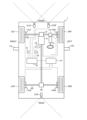
- FIG. 2 is a schematic diagram showing a configuration example of a vehicle 1 equipped with the vehicle control system 10 of this embodiment.
- the vehicle 1 has a driving force section 9 that generates driving torque for the vehicle.
- the driving force unit 9 may be an internal combustion engine such as a gasoline engine or a diesel engine, or may be a driving motor, or may include both an internal combustion engine and a driving motor.
- the vehicle 1 may be an electric vehicle equipped with two drive motors, for example, a front wheel drive motor and a rear wheel drive motor, and may be an electric vehicle equipped with a drive motor corresponding to each wheel 3. There may be.
- the vehicle 1 is an electric vehicle or a hybrid electric vehicle, the vehicle 1 includes a secondary battery that stores power to be supplied to the drive motor, or a motor or fuel cell that generates power to be charged to the battery.
- a generator will be installed.
- the vehicle 1 includes a driving force section 9, an electric steering device 15, and brake devices 17LF, 17RF, 17LR, and 17RR (hereinafter referred to as "brake devices 17" when no particular distinction is required) as devices used for driving control of the vehicle 1. ).
- the driving force section 9 outputs a driving torque that is transmitted to the front wheel drive shaft 5F and the rear wheel drive shaft 5R via a transmission (not shown), a front wheel differential mechanism 7F, and a rear wheel differential mechanism 7R.
- the drive of the driving force section 9 and the transmission is controlled by a vehicle drive control section 40 that includes one or more electronic control units (ECUs).
- An electric steering device 15 is provided on the front wheel drive shaft 5F.
- the electric steering device 15 includes an electric motor and a gear mechanism (not shown), and is controlled by the vehicle drive control unit 40 to adjust the steering angles of the front left wheel 3LF and the front right wheel 3RF.
- the vehicle drive control unit 40 controls the electric steering device 15 based on the steering angle of the steering wheel 13 by the driver.
- the vehicle drive control unit 41 controls the electric steering device 15 based on the set travel trajectory.
- the brake devices 17LF, 17RF, 17LR, and 17RR apply braking force to the front, rear, left, and right drive wheels 3LF, 3RF, 3LR, and 3RR, respectively.
- the brake devices 17 are configured as, for example, hydraulic brake devices, and the hydraulic pressure supplied to each brake device 17 is controlled by the vehicle drive control unit 40 to generate a predetermined braking force. If the vehicle 1 is an electric vehicle or a hybrid electric vehicle, the brake device 17 is used in combination with regenerative braking by a drive motor.
- the vehicle drive control unit 40 includes a driving force unit 9 that outputs the driving torque of the vehicle 1, an electric steering device 15 that controls the steering angle of the steering wheel or steered wheels, and a brake device 17 that controls the braking force of the vehicle 1. It includes one or more electronic control devices that control the drive.
- the vehicle drive control unit 40 may have a function of controlling the drive of a transmission that changes the speed of the output output from the drive force unit 9 and transmits the same to the wheels 3.
- the vehicle drive control unit 40 is configured to be able to acquire information transmitted from the driving support control device 100, and is configured to be able to execute automatic driving control or driving assist control of the vehicle 1.
- the vehicle 1 also includes a running sound detection device 24 that detects the running sound of the vehicle 1, an external camera 31 that includes a front camera 31LF, 31RF, and a rear camera 31R, and a sound pickup device that detects surrounding environmental sounds. an ambient environment sensor 32 having a device 32M.
- the vehicle 1 also includes an operation/behavior sensor 27, a GNSS antenna 29, and an HMI (Human Machine Interface) 43 for acquiring information about the surrounding environment of the vehicle 1.
- HMI Human Machine Interface
- the front photographing cameras 31LF, 31RF and the rear photographing camera 31R photograph the front or rear of the vehicle 1 and generate image data.
- the front camera 31LF and 31RF are configured as a stereo camera including a pair of left and right cameras
- the rear camera 31R is configured as a so-called monocular camera.
- the front photographing cameras 31LF, 31RF and the rear photographing camera 31R may each be a stereo camera or a monocular camera.
- the rear camera 31R may be omitted.
- the vehicle 1 of this embodiment includes, as the vehicle exterior photographing camera 31, a camera provided on the side mirrors 11L, 11R to photograph the left rear or right rear, in addition to the front photographing cameras 31LF, 31RF and the rear photographing camera 31R. You may be prepared.
- the driving support control device 100 has one or more processors such as a CPU (Central Processing Unit) or an MPU (Micro Processing Unit). Note that part or all of the driving support control device 100 may be configured with something that can be updated, such as firmware, or may be a program module or the like that is executed by a command from a CPU or the like.
- processors such as a CPU (Central Processing Unit) or an MPU (Micro Processing Unit).
- firmware or may be a program module or the like that is executed by a command from a CPU or the like.
- the driving support control device 100 executes a computer program to perform automatic driving control, etc., which reduces the risk of collision between the own vehicle 1, which is subject to driving support, and an obstacle that occurs in or around a blind spot area.
- the vehicle driving control for the own vehicle 1 is executed.
- the driving support control device 100 includes a processing section 110, a storage section 140, an information storage medium 150, and a communication section 170, as shown in FIG. Note that a configuration may be adopted in which some of these are omitted.
- the processing unit 110 performs various processes of this embodiment by reading and executing an application program (hereinafter also referred to as an "application”) stored in the information storage medium 150.
- an application hereinafter also referred to as an "application”
- the processing unit 110 of the present embodiment reads programs and data stored in the information storage medium 150, temporarily stores the read programs and data in the storage unit 140, and processes the programs and data based on the programs and data. You may do so.
- the processing unit 110 performs various processes using the main storage unit in the storage unit 140 as a work area.
- the functions of the processing unit 110 are realized by hardware such as various processors (CPU, DSP, etc.) or by application programs.
- the processing unit 110 includes a communication control unit 111, a surrounding environment detection unit 112, a vehicle data acquisition unit 113, a driver image acquisition unit 114, a running sound recognition processing unit 115, a driving condition setting unit 116, and a notification control unit 117. It consists of Note that a configuration may be adopted in which some of these are omitted.
- the communication control unit 111 performs processing for transmitting and receiving data with the management server 20.
- the communication control unit 111 controls the communication unit 170 and executes network communication including vehicle-to-vehicle communication, road-to-vehicle communication, mobile communication network, and the like.
- the surrounding environment detection unit 112 detects information regarding the surrounding environment of the vehicle based on the image data transmitted from the vehicle exterior camera 31 and the data transmitted from the surrounding environment sensor 32. Specifically, the surrounding environment detection unit 112 performs image processing on the image data transmitted from the outside camera 31, and uses object detection technology to detect people, other vehicles, and bicycles around the own vehicle 1. , buildings, natural objects, and other obstacles.
- the surrounding environment detection unit 112 calculates the positions of these objects with respect to the own vehicle 1, or the distance and relative speed between the own vehicle 1 and these objects. Then, the surrounding environment detection unit 112 stores data on the detected obstacles around the own vehicle 1 in the storage unit 140 as time-series data.
- the surrounding environment detection unit 112 detects surrounding environment sound based on data transmitted from the surrounding environment sensor 32 (sound collection device 32M).
- the surrounding environment detection unit 112 detects the driver's blind spot, such as the blind spot area formed by obstacles around the own vehicle 1, based on various information transmitted from devices outside the vehicle through V2X communication or the like. Various types of blind spot areas may be identified. For example, in this case, the surrounding environment detection unit 112 identifies the blind spot area according to the position, type, size, etc. of the obstacle based on various information.
- the surrounding environment detection unit 112 identifies the position of the own vehicle 1 on the map data using the position information of the own vehicle 1 acquired by the GNSS antenna 29, and uses the information on obstacles around the own vehicle 1 as described above.
- the blind spot area may be identified based on the following.
- the vehicle data acquisition unit 113 acquires data on the operating state and behavior of the own vehicle 1 based on the sensor signal transmitted from the vehicle operation/behavior sensor 27.
- data on the operating state and behavior of the host vehicle 1 includes vehicle speed, longitudinal acceleration, lateral acceleration, yaw rate, steering angle of the steering wheel or steered wheels, accelerator opening, brake operation amount, brake lamp switch on/off, turn signal switch Contains on/off data.
- the data on the operating state and behavior of the host vehicle 1 includes data on whether the automatic driving mode of the host vehicle 1 is on or off.
- the vehicle data acquisition unit 113 stores the acquired data on the operating state and behavior of the own vehicle 1 in the storage unit 140 as time-series data.
- the running sound recognition processing unit 115 acquires information regarding the running sound of the host vehicle 1 based on the blind spot area as running sound related information. Then, based on the acquired running sound related information, the running sound recognition processing unit 115 determines whether the running sound of the own vehicle 1 can be recognized, including the volume of the running sound of the own vehicle 1 in the detected blind spot area. Determine.
- the driving condition setting unit 116 sets driving conditions for executing vehicle driving control related to automatic driving or assisting the driver's driving based on whether or not the driving sound of the own vehicle 1 is recognized as determined by the driving sound recognition processing unit 115. Execute the operating condition setting process to set the The driving condition setting unit 116 then provides information on the set driving conditions (hereinafter referred to as “driving condition information”) to the vehicle drive control unit 40.
- the driving condition setting unit 116 sets at least the running trajectory and vehicle speed so that the own vehicle 1 does not come into contact with obstacles when the own vehicle 1 is automatically driven along a route to a set destination. Then, a control command is transmitted to the vehicle drive control section 40. Further, at this time, the driving condition setting unit 116 sets the traveling trajectory and vehicle speed of the own vehicle 1 using the risk potential, which is an index indicating the possibility that the own vehicle 1 will collide with an obstacle.
- the notification control unit 117 performs various controls for notifying the driver of the set driving conditions by controlling the driving of the HMI 43.
- the notification control unit 117 of this embodiment notifies the driver of the set driving conditions after the driving control of the host vehicle 1 is performed.
- the notification control unit 117 may issue a warning message such as "Please pass on the left side of the road to ensure a distance from the pedestrian.” “I did it.” Further, for example, when the vehicle speed is reduced, the notification control unit 117 notifies the vehicle that "the speed has been reduced to ensure the safety of pedestrians.” Note that the notification control unit 117 notifies the driver by, for example, at least one of audio and display.
- the notification control unit 117 does not necessarily need to notify the driver of the driving conditions for automatic driving control.
- the storage unit 140 serves as a work area for the processing unit 110 and the like, and its functions are realized by hardware such as RAM (VRAM).
- the storage unit 140 of this embodiment includes a main storage unit 141 that is used as a work area, and a data storage unit 142 that stores data used when executing each process.
- the data storage unit 142 stores, in addition to computer programs, table data, and risk distribution data, standard data and reference data for performing various processes.
- the computer program is a program for causing a processor to execute various operations that should be executed by the driving support control device 100. Further, the computer program may be recorded on a recording medium built into the driving support control device 100 or any recording medium that can be externally attached to the driving support control device 100.
- the information storage medium 150 is readable by a computer, and may store various applications and various data such as an OS (operating system).
- the information storage medium 150 is configured by a storage element, a magnetic disk, an optical disk, a flash memory, or the like.
- the communication unit 170 performs various controls for communicating with devices outside the vehicle (not shown), and its functions are configured by hardware such as various processors or communication ASICs, computer programs, and the like.
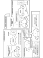
- FIGS. 3 and 4 are diagrams for explaining the driving support control process including the driving condition setting process of this embodiment.
- the driving support control device 100 of the present embodiment uses a risk level that indicates whether or not there is a risk that the driver feels about obstacles around the own vehicle 1, and the degree of risk, so that the own vehicle 1 can be controlled while reducing the risk that the driver feels.
- Executes vehicle driving control such as automatic driving. That is, in order to increase the reliability of automatic driving control or driving assist control, when an obstacle is detected, the driving support control device 100 not only avoids the obstacle but also prevents the driver from taking risks with respect to the obstacle. Execute vehicle driving control that reduces the factors that make you feel.
- the driving support control device 100 of the present embodiment takes into consideration the risk that the running sound of pedestrians who are present in the blind spot area of the driver of an electric vehicle or the like cannot be recognized or is difficult to recognize. It has a configuration for setting operating conditions for the vehicle 1.
- a vehicle 1 with an engine basically makes a louder running noise than an electric vehicle, so it is in a blind spot area that cannot be recognized from the vehicle. In many cases, the vehicle can also be recognized by the sound of the vehicle running.
- a vehicle 1 such as an electric car that runs quietly has a significantly lower running noise than an engine vehicle, so pedestrians and others in the blind spot can hear the sound of the running noise. It is difficult to recognize by In addition, if the vehicle itself cannot be recognized as described above, there is a high risk that a situation of insufficient information such as a pedestrian colliding with the vehicle 1 will occur.
- the driving support control device 100 of the present embodiment determines whether or not the running sound of the host vehicle 1 can be recognized in the blind spot area that is the driver's blind spot, sets a new risk, and sets a new risk for the host vehicle 1 including the risk. It has a configuration for setting driving conditions and executing driving support control processing associated therewith.
- the driving support control device 100 when the driving support control device 100 detects a blind spot area that is a driver's blind spot, the driving support control device 100 adjusts the driving of the own vehicle 1 based on the blind spot area as seen from the own vehicle 1.
- the vehicle is configured to execute an information acquisition process to acquire information regarding sound as traveling sound related information.
- the driving support control device 100 performs a determination process (hereinafter referred to as "driving sound It has a configuration that executes "recognition determination processing").
- the driving support control device 100 has a configuration that executes a driving condition setting process that sets driving conditions for the host vehicle based on the determination result of the running sound recognition determination process. There is.
- the driving support control device 100 of the present embodiment executes a setting process for setting driving conditions at each predetermined timing during driving support, and each time the driving condition is set, the driving support control device 100 It has a configuration that controls. That is, the driving support control device 100 has a configuration that controls the host vehicle 1 during driving support in accordance with the driving situation or driving environment that changes moment by moment, including the blind spot area.
- the driving support control device 100 of the present embodiment is configured to recognize the obvious noise of obstacles around the own vehicle 1 when the running sound of the own vehicle 1 can be recognized in the blind spot area. It has a configuration that sets driving conditions based on risks and potential risks to blind spot areas. On the other hand, as shown in FIG. 4 [3], if the driving support control device 100 cannot recognize the running sound of the own vehicle 1 in the blind spot area, in addition to the actual risk and the latent risk, the driving support control device 100 The system is configured to set operating conditions based on the assumption that the running sound may not be recognized.
- the driving support control device 100 of the present embodiment performs driving based on risk distribution data showing a risk distribution that reflects the above-mentioned actual risk and latent risk as well as the risk of not being able to recognize running sounds, or a risk map that illustrates the risk distribution data. It has a configuration for setting conditions.
- FIG. 4 [1] shows that a blind spot area is detected using image data etc. acquired by the external photographic camera 31 during automatic driving control based on an already set route and speed. Further, in FIG. 4 [2], information acquisition processing is executed to acquire the running sound of the own vehicle 1 or the surrounding environmental sound by the running sound detection device 24 and the sound collection device 32M, respectively, as running sound related information. It is shown that the running sound recognition determination process is executed accordingly. Furthermore, FIG. 4 [3] shows that, as a driving condition setting process, the risks assumed are different depending on whether the running sound can be recognized or not recognized by the above-mentioned running sound recognition determination process, and the different risks. It is shown that the operating conditions are set respectively.
- the driving support control device 100 of the present embodiment can reduce the risk that occurs around the driver's blind spot due to low or difficult to recognize running noise of an electric vehicle, etc., by adjusting the speed and route of the vehicle. This can be reflected in operating conditions such as Therefore, the driving support control device 100 of the present embodiment is capable of realizing driving support control that avoids or reduces risks such as collision between the own vehicle and an obstacle that is a target of driving support that occurs around the blind spot area. can.
- FIG. 5 is an explanatory diagram illustrating a risk value (risk potential) indicating the value of risk with respect to an obstacle in this embodiment, and is a diagram illustrating an example when a pedestrian is used as the obstacle.
- FIG. 6 is a diagram for explaining risk distribution data (risk map) composed of standard risk potentials in this embodiment.
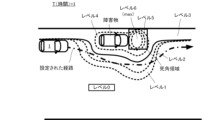
- FIG. 7 is a diagram for explaining risk distribution data (risk map) in which the risk of not being able to recognize running sounds is reflected in the reference risk potential in this embodiment.
- the risk potential increases as you get closer to the obstacle (pedestrian). Since the risk potential can be expressed as an exponential function with respect to the distance xi from each obstacle, it is expressed by, for example, the following equation (1). Note that “Ri” is the risk value which is the risk potential, “Ci” is the absolute risk value (gain), “xi” is the distance from the obstacle, “Ti” is the gradient coefficient, and “ri” is The radius of the obstacle and "i” indicate the numbering for distinguishing the obstacle. Further, the gradient coefficient Ti is a value that is set regardless of obstacles.
- the absolute risk value Ci which is the risk value when the distance xi between the host vehicle 1 and the obstacle is zero, is set in advance for each obstacle as a value that depends on the obstacle. For example, if the obstacle is a ⁇ pedestrian'' or ⁇ a low curb,'' a collision with a pedestrian is considered to be a higher risk than a collision with a short kerb, and the risk to the ⁇ pedestrian.'' The absolute value Ci is set to a value larger than the absolute risk value Ci for the "short curb".
- the risk distribution data assigns a predetermined risk value to each obstacle detected while the own vehicle 1 is moving, and indicates the spatial overlap of the risk values of each obstacle. It is a data of the height of the sky on a two-dimensional plane. That is, the risk distribution data is two-dimensional distribution data of risk values Ri that reflect the risk of collision with a plurality of obstacles existing in the direction of travel of the vehicle.
- a "risk map" is a graphical representation of this risk distribution data. In other words, a risk map is a map that represents the height of risk potential as contour lines on a two-dimensional plane.
- the risk distribution data (or risk map)
- the risk distribution data of this embodiment includes standard risk potentials of a risk potential based on obstacles as an actual risk, and a latent risk potential (i.e., latent risk) based on a blind spot area that is a driver's blind spot. It will be done. That is, in addition to the risk value Ri (actual) of the actual risk, the risk distribution data includes the risk value Ri (potential) of the latent risk that may come into contact with an obstacle that has not become obvious due to the existence of a blind spot area. ) is included.
- potential risks include the risk of a passerby jumping out of the blind spot of a vehicle when passing through a blind spot formed by an obstacle of a vehicle parked on a side road.
- the risk distribution data is basically a standard risk that spatially overlaps the risk value Ri (actual) of the actual risk and the risk value Ri (potential) of the latent risk. This is potential distribution data.
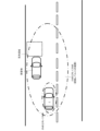
- FIG. 6 there is an obstacle (vehicle) and a blind spot area formed due to the obstacle (vehicle) in the left front of the own vehicle 1, and the level of the risk value of the standard risk potential (hereinafter referred to as "risk level").
- risk level the level of the risk value of the standard risk potential
- the risk distribution data of this embodiment includes, in addition to the above-mentioned standard risk potential, a running sound unrecognizable risk that indicates the risk of whether or not the running sound of the host vehicle 1 can be recognized within the blind spot area formed by the obstacle. is reflected. That is, in this embodiment, in order to reflect the possibility that an obstacle such as a pedestrian will jump out onto the route from the blind spot area and come into contact with the host vehicle 1 in the risk distribution data, the risk of not being able to recognize the driving sound is used.
- the risk of not being able to recognize the running sound of the present embodiment is that the risk increases when the running sound of the own vehicle 1 within the blind spot area cannot be recognized. This is a risk that increases the risk around the blind spot area compared to the case where the
- the value of the risk potential (i.e., risk value) of the risk of not being able to recognize a running sound in this embodiment is set by increasing the standard risk potential level (i.e., risk level) of the blind spot area by one.
- the risk distribution data set based on the standard risk potential becomes data in which the risk level is increased by one in the vicinity of the blind spot area when the sound of the own vehicle 1 is recognizable in the blind spot area.
- risk distribution data when increasing risk level 0 to risk level 6 by one not only in the vicinity of the blind spot area but also in the range where driving conditions such as routes are affected by the risk to the blind spot area is analyzed. It is designed to be used. In principle, changing the risk level only around the blind spot area is sufficient from the perspective of avoiding risk. However, if the route as a driving condition changes according to a change in risk potential while the own vehicle 1 is running, it is necessary to smoothly change the traveling trajectory of the own vehicle 1, so it is necessary to assign a risk level. be. Therefore, in this embodiment, as described above, as shown in FIG. 7, when reflecting the risk of not being able to recognize running sounds in the risk distribution data, It is designed to change the level.
- FIG. 7 shows risk distribution data when the sound of the own vehicle 1 in the blind spot region cannot be recognized.
- FIG. 7 shows data in which risk level 0 to risk level 6 are raised by one not only in the vicinity of the blind spot area but also in the entire risk distribution data that should reflect the risk of not being able to recognize running sounds. However, even in this case, the risk level is maintained at a maximum of "6".
- blind areas are not shown to avoid clutter.
- a fluctuation value for changing the risk value indicating the reference risk potential of the blind spot area may be used as the risk value of the risk of not being able to recognize the running sound.
- a risk value indicating the risk of not being able to recognize a running sound may be used, such as doubling the risk value indicating the standard risk potential.
- the risk level is maintained at a maximum of "6".
- the actual risk preset for obstacles, the potential risk preset for the blind spot area, and whether or not the running sound of the own vehicle 1 in the blind spot area can be recognized.
- risk distribution data that includes the risk of not being able to recognize running sounds.
- the running sound recognition processing unit 115 detects the running sound of the host vehicle 1 based on the blind spot area from the running sound detection device 24 and the surrounding environment sensor 32.
- the included information (hereinafter referred to as "running sound related information") is acquired. That is, the running sound recognition processing unit 115 determines whether the running sound of the own vehicle 1 can be recognized in the blind spot area, such as the volume of the running sound of the own vehicle 1 and the type and volume of the surrounding environmental sound of the own vehicle 1.
- the information used to determine this is acquired as running sound related information.
- the running sound recognition processing unit 115 acquires running sound information of the host vehicle 1 from the running sound detection device 24 when repeatedly executing the running sound recognition determination process at predetermined timings. Then, as shown in FIG. 4 [2] above, the running sound recognition processing unit 115 determines the volume of the running sound of the own vehicle 1 based on the acquired running sound information and the distance from the own vehicle 1 to the blind spot area. , the running sound related information is acquired by estimating the volume of the running sound in the blind spot area. In particular, the running sound recognition processing unit 115 calculates the volume of the running sound of the own vehicle 1 and the attenuation rate based on the distance (for example, the shortest distance) from the own vehicle 1 to the blind spot area at each predetermined timing. is used to estimate the volume of the running sound of the host vehicle 1 in the blind spot area.
- the running sound recognition processing unit 115 uses information about the surrounding environment sound detected by the surrounding environment detection unit 112 (hereinafter referred to as (referred to as "surrounding environment sound information").
- the running sound recognition processing unit 115 receives running sound related information via a wireless communication network (not shown) and the communication unit 170 by V2X communication. may be obtained.
- the running sound recognition processing unit 115 detects the running sound of the host vehicle 1 that is picked up by a microphone (not shown) installed in a blind spot area or a telephone pole around the blind spot area or on the road surface. , may be acquired as running sound related information within the blind spot area. In this case, the running sound recognition processing unit 115 may acquire running sound-related information including ambient environmental sounds within the blind spot area, or may acquire running sound related information including ambient environmental sounds within the blind spot area, or Only the running sound may be acquired as the running sound related information.
- the running sound recognition processing unit 115 collects information for determining whether or not the running sound of the own vehicle 1 that can be recognized within the blind spot area is recognized. It may also be acquired as running sound related information. For example, in addition to the running sound information of the own vehicle 1, the running sound recognition processing unit 115 may also detect the position of an obstacle based on a satellite signal from a GPS satellite, the position of the own vehicle 1, and the sound absorption and reflected sound related to the obstacle. Reference data and the like may be acquired as the running sound related information.
- FIG.8 and FIG.9 is a figure for demonstrating the running sound recognition determination process performed by the vehicle control system 10 of this embodiment.
- the running sound recognition processing unit 115 recognizes whether or not the running sound of the host vehicle 1 within the blind spot area is recognized, the volume of the running sound, or both, based on the running sound related information acquired through the information acquisition process. Execute running sound recognition determination processing. In particular, when a blind spot area is detected, the running sound recognition processing unit 115 repeatedly executes the running sound recognition determination process at predetermined timings until the blind spot area is passed, in conjunction with the driving condition setting process.
- the running sound recognition processing unit 115 detects the running sound of the own vehicle 1 in the blind spot area based on the volume of the running sound of the own vehicle 1 in the blind spot area included in the running sound related information acquired by the information acquisition process. Recognize the presence or absence of sound. In particular, the running sound recognition processing unit 115 determines that the running sound of the own vehicle 1 in the blind spot area cannot be recognized when the volume of the running sound of the own vehicle 1 in the blind spot area is "0" or less.
- the surrounding environment detection unit 112 directly uses this information to recognize the running sound of the own vehicle 1 in the blind spot area. It is also possible to determine whether or not it is possible.
- the running sound recognition processing unit 115 uses the distance (center) from the own vehicle 1 to the blind spot area when estimating the volume of the running sound in the blind spot area. and width may also be used.
- the running sound recognition processing unit 115 may use an attenuation rate based on the position, type, and size of the obstacle.
- the running sound recognition processing unit 115 Based on the running sound related information, the running sound recognition processing unit 115 not only determines whether or not the running sound of the host vehicle 1 in the blind spot area can be recognized, but also determines whether the running sound is difficult to recognize (i.e., whether the running sound is difficult to recognize). Recognizable situations (hereinafter also referred to as "recognizable situations") such as gender) may be determined.
- the recognition situation changes in the blind spot area such as whether the running sound of the own vehicle 1 can be heard, is difficult to hear, or cannot be heard, the risks around the blind spot area will also change, and the driving conditions of the own vehicle 1, such as the route and speed, will also change. It is necessary to do so.
- the running sound recognition processing unit 115 of the present embodiment sets driving conditions based on an accurate understanding of risks assumed around the blind spot area. It may have a configuration for determining.
- the running sound recognition processing unit 115 of the present embodiment identifies the volume of the running sound of the own vehicle 1 based on the acquired running sound related information, and makes it possible to recognize the running sound of the own vehicle 1 in the blind spot area. Assess the situation. For example, the running sound recognition processing unit 115 may identify the volume of running sounds around the own vehicle 1 and determine whether the running sound of the own vehicle 1 in the blind spot area can be recognized. The volume may be specified to determine whether the sound of the host vehicle 1 in the blind spot region can be recognized.
- the running sound recognition processing unit 115 sets the volume level range of the running sound of the own vehicle 1 in the blind spot area in advance to, for example, a level where the running sound of the own vehicle 1 can be heard, a level where it is hard to hear, and a level where it cannot be heard. , set in stages (for example, three stages). Further, as described above, the running sound recognition processing unit 115 determines to which level range the volume of the running sound of the own vehicle 1 in the estimated blind spot area belongs. Then, the running sound recognition processing unit 115 determines each recognition possible situation in which the running sound of the own vehicle 1 in the blind spot area is "audible", “hard to hear", or "inaudible", depending on the level range to which it belongs. Identify.
- the volume level of running sound is divided into four levels: less than 10 dB, 10 dB or more but less than 20 dB, 20 dB or more but less than 30 dB, and 30 dB or more.
- the recognition level RL is "1.0 (hearing)", “1.25 (hard to hear: high volume)", “1.5 (hard to hear: low volume)” and "2 .0 (cannot hear)” is set.
- the volume level of the running sound of the own vehicle 1 in the blind spot area is "10 dB”
- the running sound recognition processing unit 115 can recognize the recognition level "1.5” as shown in FIG. Set as a situation.
- the above-mentioned recognizable situation is set to a variation value (specifically, from “1.0” to "1.0") for varying the value of the risk potential of the risk distribution data. 2.0), the details of which will be described later.
- the running sound recognition processing unit 115 of the present embodiment determines whether the own vehicle 1 is running in the blind spot area based on the running sound related information.
- the volume level of the sound may also be specified. Then, the running sound recognition processing unit 115 may determine the recognition state based on the volume level of the running sound of the host vehicle 1 within the specified blind spot area.
- the running sound recognition processing unit 115 of the present embodiment detects the running sound of the own vehicle 1 in the blind spot area based on the volume of the running sound of the own vehicle 1 in the blind spot area, as well as the volume, type, or both of the surrounding environment sound in the blind spot area. It may also be determined whether or not the running sound of the vehicle can be recognized.
- the running sound related information of the present embodiment includes running sound information indicating the volume of the running sound of the host vehicle 1, and surrounding environment sound information having at least one of the volume and type of the surrounding environment sound in the blind spot area. , contains information on.
- the running sound recognition processing unit 115 of the present embodiment may execute the running sound recognition determination process based on the running sound information and the surrounding environment sound information.
- the own vehicle 1 in the blind spot area is It is difficult to determine whether a particular running sound is acceptable or not based only on one running sound.
- FIG. 9 shows an example in which the volume of the running sound of the host vehicle 1 in the blind spot area is lower than 20 dB, and the level crossing warning sound as the surrounding environment sound in the blind spot area is 40 dB. In the blind spot area, the sound of the vehicle 1 running is drowned out.
- the running sound recognition processing unit 115 of the present embodiment estimates the volume, type, or both of the surrounding environmental sounds in the blind spot area, and based on the relationship between the running sound of the own vehicle 1 and the surrounding environmental sound, the running sound recognition processing unit 115 It may be determined whether or not the running sound of the own vehicle 1 can be recognized.
- the running sound recognition processing unit 115 detects the volume and direction of the sound source of the surrounding environmental sound at the position of the host vehicle 1 based on the data detected by the surrounding environment sensor 32 and the surrounding environmental sound information. Furthermore, the running sound recognition processing unit 115 refers to the amplification factor and attenuation rate associated with the distance based on the volume of the surrounding environment sound, the direction of the sound source, and the distance from the own vehicle 1 to the blind spot area, and calculates the blind spot area. Estimate the volume of environmental sounds at. Then, the running sound recognition processing unit 115 determines whether or not there is a running sound of the host vehicle 1 in the blind spot area, based on the acquired volume of the running sound in the blind spot area and the estimated volume of ambient environmental sound in the blind spot area. Recognize the volume (relative volume) of running sounds, or both.
- the running sound recognition processing unit 115 detects the blind spot. It is determined that the running sound of the own vehicle 1 is recognizable in the area. Further, in this case, the running sound recognition processing unit 115 determines that the running sound of the own vehicle 1 cannot be recognized in the blind spot area if the volume of the running sound is lower than the volume of the surrounding environmental sound. However, even in this case, if the difference between the volume of the running sound and the volume of the surrounding environment sound is "0", the running sound recognition processing unit 115 recognizes the running sound of the own vehicle 1 in the blind spot area. It may be determined that it is difficult.
- the predetermined condition for the volume of the running sound of the own vehicle 1 and the volume of the surrounding environment sound is that the volume of the running sound is larger than the volume of the surrounding environment sound. It may also be specified that the amplitude is greater than a predetermined magnitude (for example, greater than or equal to 10 dB).
- the running sound recognition processing unit 115 directly uses these information to detect the blind spot. It may also be determined whether the sound of the own vehicle 1 in the area is recognized.
- the running sound recognition processing unit 115 uses the difference between the volume of the running sound of the own vehicle 1 in the blind spot area and the volume of the ambient environmental sound to determine whether the running sound of the own vehicle 1 in the blind spot area is A ratio between the volume of the running sound and the volume of the surrounding environmental sound may be used.
- the surrounding environment detection unit 112 determines that "a ⁇ 1" when the ratio of the volume X of the running sound of the vehicle 1 in the blind spot area to the volume Y of the surrounding environment sound is (Formula 2). In this case, it is determined that the sound of the host vehicle 1 in the blind spot area cannot be recognized. On the other hand, in this case, the surrounding environment detection unit 112 determines that the running sound of the own vehicle 1 in the blind spot area is recognizable when "a>1".
- the running sound recognition processing unit 115 detects the distance from the own vehicle 1 to the blind spot area when estimating the volume of the running sound in the blind spot area.
- the distance eg, center distance
- the running sound recognition processing unit 115 may use an attenuation factor or amplification factor (including reflected sound) based on the position, type, and size of the obstacle.
- the running sound recognition processing unit 115 of this embodiment directly estimates the volume of the surrounding environment sound in the blind spot area based on the data detected by the surrounding environment sensor 32 and the surrounding environment sound information. It may be estimated based on the type of environmental sound. In this case, the running sound recognition processing unit 115 indirectly estimates the volume of the surrounding environmental sound based on the type of the surrounding environmental sound, the direction of the sound source, and the distance between the sound source and the blind spot area.
- the running sound recognition processing unit 115 recognizes the running sound of the host vehicle 1 in the blind spot area based on the frequency component of the running sound, etc., instead of the volume of the running sound. It is also possible to determine whether or not it is possible. In particular, the running sound recognition processing unit 115 determines whether the running sound of the own vehicle 1 in the blind spot area can be recognized based on the frequency component of the running sound of the own vehicle 1 in the blind spot area and the frequency component of the surrounding environmental sound. It's okay.
- the running sound recognition processing unit 115 has a property that the running sound is canceled out when the frequency component of the running sound in the blind spot area is the same as the frequency component of the sound included in the surrounding environmental sound but has the opposite phase. may be used to determine whether the sound of the host vehicle 1 in the blind spot area can be recognized.
- the running sound recognition processing unit 115 performs frequency analysis on the running sound of the host vehicle 1 in the blind spot area based on the running sound related information acquired by the information acquisition process, and Identify the amplitude and phase of each frequency component of the sound. Furthermore, in this case, the running sound recognition processing unit 115 performs frequency analysis on the surrounding environmental sound within the blind spot area based on the data detected by the surrounding environment sensor 32 and the surrounding environment sound information, and Identify the amplitude and phase of each frequency component of the sound.
- the running sound recognition processing unit 115 determines whether or not to cancel the running sound of the own vehicle 1 in the blind spot area based on the surrounding environmental sound in the blind spot area. In other words, the running sound recognition processing unit 115 determines whether the frequency component of the sound included in the surrounding environment sound in the blind spot area is the same as the frequency component of the running sound in the blind spot area, the amplitudes of both are the same, and the frequency components are opposite in phase. Determine whether there is a relationship.
- the running sound recognition processing unit 115 determines that the frequency component of the sound included in the surrounding environment sound in the blind spot area is the same as the frequency component of the running sound in the blind spot area, the amplitudes of both are the same, and the phase is opposite to that of the sound in the blind spot area. In this case, it is determined that the sound of the host vehicle 1 in the blind spot area cannot be recognized. Further, the running sound recognition processing unit 115 determines whether the frequency component of the sound included in the surrounding environment sound in the blind spot area is not the same as the frequency component of the running sound in the blind spot area, the amplitudes of both are not the same, or the relationship is in opposite phase. If not, it is determined that the sound of the host vehicle 1 in the blind spot area can be recognized.
- FIGS. 10 and 11 are diagrams for explaining the driving condition setting process executed by the vehicle control system 10 of this embodiment.
- the driving condition setting unit 116 monitors the surrounding environment of the own vehicle 1 including obstacles and blind spots, and its operating state and behavior at predetermined timings during driving support for the own vehicle 1. An operating condition setting process is executed to set operating conditions based on the changing situation.
- the driving condition setting unit 116 acquires image data acquired by the external camera 31 and data on the surrounding environment of the host vehicle 1 specified by the surrounding environment sensor 32 as the constantly changing situation. do. At this time, the driving condition setting unit 116 acquires the presence or absence of an obstacle and its type, the presence or absence of a blind spot area, and the position and size relative to the own vehicle 1 as data on the surrounding environment. Then, when a blind spot area exists, the driving condition setting unit 116 obtains the result of the running sound recognition determination process indicating whether the running sound of the host vehicle 1 can be recognized in the blind spot area.
- the driving condition setting unit 116 determines the route that the host vehicle 1 will travel and the route that the host vehicle 1 will travel based on the determination result of the running sound recognition determination process.
- the speed at which the vehicle 1 is traveling is set as the driving condition.
- the driving condition setting unit 116 executes a driving condition setting process that repeatedly sets driving conditions at predetermined timings until the vehicle passes through the blind spot area.
- the driving condition setting unit 116 of the present embodiment takes risks based on obstacles around the own vehicle 1, reflecting the determination results of the running sound recognition determination process. Use quantified risk potential. That is, in order to use the risk potential, the driving condition setting unit 116 of the present embodiment sets the driving conditions by using risk distribution data that reflects the risk of not being able to recognize the running sound in the reference risk potential that includes the actual risk and the latent risk. Set.
- the driving condition setting unit 116 provides the set driving conditions including the route and speed of the own vehicle 1 to the vehicle drive control unit 40 as driving condition information.
- the operating condition setting unit 116 sets operating conditions within a range not exceeding these. Further, the operating condition setting unit 116 of this embodiment executes the operating condition setting process, for example, every 100 ⁇ (sec) as a predetermined timing. However, the predetermined timing depends on the processing capacity of the ECU.
- the driving condition setting unit 116 determines the risk as a spatial risk potential with respect to the traveling direction of the own vehicle 1 based on the acquired surrounding environment of the own vehicle 1 and the result of the running sound recognition determination process at each predetermined timing. Set distribution data. In particular, when it is determined that the running sound of the host vehicle 1 cannot be recognized in the blind spot area, the driving condition setting unit 116 spatially reflects the running sound risk potential around the blind spot area along with the reference risk potential. Set the risk distribution data.
- the driving condition setting unit 116 creates a reference risk potential consisting of a spatial overlap between an actual risk due to a spatial obstacle and a latent risk caused by the existence of a blind spot area. Set.
- the driving condition setting unit 116 specifies the spatial distribution of the risk potential of the actual risk in the traveling direction of the own vehicle 1 based on the type, size, and position of the obstacle and the relative speed with respect to the own vehicle 1. do. Further, the driving condition setting unit 116 sets a distribution of risk potential as a latent risk in the traveling direction of the own vehicle 1 based on the size and position of the blind spot area and the relative speed with respect to the own vehicle 1. Then, the driving condition setting unit 116 spatially adds the risk potential distributions of the actual risk and the latent risk, and sets a reference risk potential that has a spatial distribution with respect to the position of the own vehicle 1.
- the driving condition setting unit 116 sets a running sound unrecognizable risk indicating the risk of whether or not the running sound of the own vehicle 1 around the blind spot area can be recognized, based on the obtained result of the running sound recognition determination process. .
- the driving condition setting unit 116 sets (referred to as "the area around the blind spot"). For example, the driving condition setting unit 116 identifies an area where there is a risk of collision if an obstacle such as a pedestrian jumps out of the corresponding blind spot area, as the area around the blind spot.
- the driving condition setting unit 116 sets a spatial predetermined risk potential (i.e., a running sound risk potential) with respect to the traveling direction of the own vehicle 1 in the identified blind spot surrounding area based on the acquired running sound recognition determination process. Set. In particular, if it is determined that the running sound of the own vehicle 1 in the corresponding blind spot area is not recognizable, the driving condition setting unit 116 determines that the risk based on the blind spot area is high and sets the risk potential in the blind spot area. Set the running noise risk potential to make it higher.
- a spatial predetermined risk potential i.e., a running sound risk potential
- the driving condition setting unit 116 calculates the comprehensive distribution of each spatial risk potential (i.e., risk distribution data) based on the reference risk potential and the running sound risk potential. Set.
- the running sound recognition judgment is such that the running sound of the own vehicle 1 in the blind spot area can be recognized. Assume that the processing results are obtained.
- the operating condition setting unit 116 sets risk distribution data for raising the level according to the reference risk potential by one level.
- FIG. 10 shows a case where a value for raising the level by one is reflected for the standard risk potential of risk levels 1 to 6 when the running sound of the own vehicle 1 cannot be recognized in the blind spot area. An example is shown.
- the risk distribution data is set as the running sound risk potential by varying the reference risk potential according to the recognizable level as the recognizable situation of the running sound in the blind spot area.
- the variation values of "2.0", “1.5”, “1.25" and “1" are set depending on the recognizable level (specifically, the volume level range). It is assumed that
- the driving condition setting unit 116 sets the risk level to the standard risk potential near the blind spot area, as shown in FIG. Risk distribution data is set by multiplying the running noise risk potential.
- FIG. 11 shows an example where each risk level is twice the standard risk potential.
- risk level 3 in the standard potential becomes risk level 6 when the driving sound risk potential is reflected.
- risk level 2 in the standard potential becomes risk level 6. If the potential is reflected, the risk level will be 4. Furthermore, even in this case, the highest risk level is set not to exceed "6".
- the driving condition setting unit 116 refers to data on the current operating state and behavior of the own vehicle 1 and determines the route and speed at which the own vehicle 1 should travel based on risk distribution data set at each predetermined timing. Set. Specifically, based on the set risk distribution data, the driving condition setting unit 116 determines whether the own vehicle 1 is able to travel and whether the own vehicle 1 is traveling in the direction of travel and the current speed. Establish appropriate operating conditions that reduce risk. In particular, as shown in FIG. 10 or 11, for example, the driving condition setting unit 116 sets driving conditions such as routes, speeds, and combinations thereof that allow the own vehicle 1 to travel at a low risk and at an appropriate speed. Set as .
- driving conditions predetermined speed at risk level 1 that maintain the same risk as conventional driving support even if the risk in the risk distribution data becomes higher are set.
- An example is shown below.
- the driving condition setting unit 116 gives priority to setting the new route, and the driving condition setting unit 116 prioritizes setting of the new route while maintaining the current speed. (more than an angle), set operating conditions for deceleration.
- the driving condition setting unit 116 does not set the running sound risk potential and only sets the reference risk potential. Set operating conditions based on
- the driving condition setting unit 116 sets driving conditions such as equipment or devices used when the vehicle is running, such as the volume of sound emitted by the own vehicle 1, turning on and off headlights, or switching the optical axis.
- the conditions for control may be set as operating conditions.
- FIGS. 12 and 13 are flowcharts showing the operation of the driving support control process including the driving condition setting process executed by the driving support control device 100 of this embodiment.
- the driving condition setting unit 116 detects the start of driving support control processing such as automatic driving (step S101), it executes preprocessing such as initialization of the driving support control device 100 (step S102). . Note that at this time, the running sound detection device 24, the vehicle exterior photographing camera 31, and the surrounding environment sensor 32 start operations for the automatic driving mode.
- the driving condition setting unit 116 determines whether an instruction to terminate the automatic driving mode, such as a driver's instruction, has been received (step S103). At this time, if the driving condition setting unit 116 determines that an instruction to end the driving support control process has been received, it ends this operation, and if it determines that the end instruction has not been received, the driving condition setting unit 116 performs the process in step S104. to be transferred to
- the surrounding environment detection unit 112 determines that the instruction to end the driving support control process has not been received, the surrounding environment detection unit 112 detects image data or surrounding environment detection data transmitted from the outside camera 31 and the surrounding environment sensor 32. (Step S104).
- the surrounding environment detection unit 112 recognizes the surrounding environment such as obstacles around the own vehicle 1 based on the detected data (step S105).
- the surrounding environment detection unit 112 determines (detects) the presence or absence of a blind spot area from the recognized surrounding environment (step S106). In particular, the surrounding environment detection unit 112 determines whether there is a blind spot area that is a blind spot of the driver, based on various data transmitted from the outside camera 31 or the surrounding environment sensor 32.
- the driving condition setting unit 116 works in conjunction with the vehicle drive control unit 40 to detect the presence of a recognized obstacle or the like in the own vehicle.
- Guidance control of the host vehicle 1 is performed based on the surrounding environment of the host vehicle 1 (step S107). That is, when an obstacle exists, the driving condition setting unit 116 specifies the type, position, size, and relative speed of the vehicle 1 of the obstacle, and determines whether the obstacle is caused by the presence of the obstacle. The host vehicle 1 executes guidance control to avoid the obstacle, including risks.
- the driving condition setting unit 116 acquires running sound related information of the host vehicle 1 based on the target blind spot area (step S111). Specifically, the running sound recognition processing unit 115 acquires running sound information from the running sound detection device 24 and ambient environment sound information from the ambient environment sensor 32 .
- the running sound recognition processing unit 115 executes a running sound recognition determination process to determine whether the running sound of the host vehicle 1 can be recognized in the target blind spot area based on the acquired running sound related information (step S112). Specifically, the running sound recognition processing unit 115 estimates the volume of the running sound of the own vehicle 1 in the blind spot area from the acquired running sound information, and estimates the volume of the surrounding environmental sound in the blind spot area from the acquired surrounding environment sound information. Estimate. Then, the running sound recognition processing unit 115 determines whether the running sound can be recognized based on the estimated volume of the running sound of the own vehicle 1 and the surrounding environment sound. However, as described above, the running sound recognition processing unit 115 may estimate the volume of the running sound of the host vehicle 1 in the blind spot area only from the acquired running sound information.
- step S112 if the running sound recognition processing unit 115 determines that the running sound of the host vehicle 1 cannot be recognized in the target blind spot area, the process proceeds to step S113. On the other hand, when the running sound recognition processing unit 115 determines that the running sound of the host vehicle 1 in the blind spot area can be recognized, the running sound recognition processing unit 115 determines that the risk distribution of the actual risk of the obstacle and the latent risk (standard risk potential) in the blind spot area The data is set (step S115) and the process moves to step S116.
- the driving condition setting unit 116 specifies the risk (risk potential) of not being able to recognize the running sound (step S113).
- the driving condition setting unit 116 sets the risk distribution data of the standard risk potential of the actual risk based on the target obstacle and the latent risk in the blind spot area, and also sets the risk of not being able to recognize the running sound specified in the risk distribution data. It is reflected (step S114).
- the driving condition setting unit 116 sets new driving conditions including the route and speed of the host vehicle 1 based on the set risk distribution data (step S116), and transmits the set driving conditions to the vehicle drive control unit 40. (Step S117).
- the surrounding environment detection unit 112 determines whether the own vehicle 1 passes through the target blind spot area around the own vehicle 1 or in the direction of travel, based on various data transmitted from the outside camera 31 or the surrounding environment sensor 32. It is determined whether or not (step S118). At this time, if the surrounding environment detection unit 112 determines that the target blind spot area is still detectable, the process proceeds to step S111, and if it determines that the target blind spot area is no longer detectable, the process proceeds to step S103. Move to processing.
- the running sound recognition determination process of this operation is repeatedly executed after the blind spot area is detected until the vehicle passes through the blind spot area, but once it is determined that the running sound cannot be recognized, the running sound cannot be recognized. Alternatively, this process may be omitted and subsequent processes may be executed. However, if the running sound recognition and judgment process is repeated until the vehicle passes through the blind spot area, it is possible to respond to changes in the relative position of the own vehicle 1 and the blind spot area. Operation control can be executed.
- FIGS. 14 to 17 are diagrams for explaining specific examples of the operation of the driving support control process including the driving condition setting process executed by the driving support control device 100 of this embodiment.
- risk distribution data having risk levels from level 0 to level 6 is formed.
- the route and speed that will result in smooth running without sudden deceleration or sudden steering will be set. do.
- the running sound recognition determination process it is assumed that the running sound of own vehicle sound 1 in the blind spot area is determined in three stages: "heard", "hard to hear", and "not audible”. Further, in the driver of this specific example, the route is set at risk level 3 or lower.
- the driving support control device 100 detects a blind spot area and determines that the running sound of the host vehicle 1 in the blind spot area cannot be recognized through the running sound recognition determination process at timing T1.
- the driving support control device 100 sets risk distribution data based on the reference risk potential and the risk of not being able to recognize the driving sound, as shown in FIG. Specifically, as shown in FIG. 14, the driving support control device 100 sets risk distribution data having risk levels 0 to 6 and reflecting the risk of not being able to recognize the driving sound in the reference risk potential.
- the driving support control device 100 operates according to the risk distribution data, the current operating state and behavior of the host vehicle 1, the predetermined upper and lower limits of acceleration/deceleration, and the upper limit of the angular velocity of the steering angle.
- a route that passes through a predetermined speed and a risk level of 3 or less is set as a driving condition. Further, the driving support control device 100 controls the vehicle drive control unit 40 to control the host vehicle 1 based on the set speed and route until the next running sound recognition determination processing execution timing.
- the risk level "3" or lower includes the range of risk levels 0, 1, and 2 extending from the solid line indicating risk level 3 toward the bottom of the drawing. Further, FIG. 14 shows an example of a route that allows smooth travel according to predetermined upper and lower limits of acceleration/deceleration when the risk level is "3" or lower.
- timing T2 arrives, and at timing 2, the driving support control device 100 detects the blind spot area and detects the running sound of the own vehicle 1 in the blind spot area through the running sound recognition determination process. A case where it is determined that it cannot be recognized will be explained.
- the driving support control device 100 sets (updates) risk distribution data based on the reference risk potential and the risk of not being able to recognize the driving sound, as shown in FIG. Specifically, as shown in FIG. 15, the driving support control device 100 sets risk distribution data whose risk level is one level higher than at timing T1.
- the driving support control device 100 uses the risk distribution data, the current operating state and behavior of the own vehicle 1, the predetermined upper and lower limits of acceleration/deceleration, and the angular velocity of the steering angle. According to the upper limit, a route passing through a predetermined speed and a risk level of 3 or less is set as a driving condition. Further, the driving support control device 100 controls the vehicle drive control unit 40 to control the host vehicle 1 based on the set speed and route until the next running sound recognition determination processing execution timing.
- FIG. 15 shows risk distribution data in which the risk level has increased by one in FIG. 14. Even if the risk level changes, a new route is set so that the route as a driving condition is at risk level 3 or lower.
- timing T3 arrives, and while the driving support control device 100 detects the blind spot area at timing T3, it determines that the running sound of the host vehicle 1 in the blind spot area is difficult to recognize through the running sound recognition determination process. Let me explain the case.
- the driving support control device 100 sets (updates) risk distribution data based on the reference risk potential and the risk of not being able to recognize the driving sound, as shown in FIG. Specifically, as shown in FIG. 16, the driving support control device 100 sets risk distribution data in which the risk level is 0.5 higher than at timing T2.
- the driving support control device 100 uses the risk distribution data, the current operating state and behavior of the own vehicle 1, the predetermined upper and lower limits of acceleration/deceleration, and the angular velocity of the steering angle. According to the upper limit, a route passing through a predetermined speed and a risk level of 3 or less is set as a driving condition. Further, the driving support control device 100 controls the vehicle drive control unit 40 to control the host vehicle 1 based on the set speed and route until the next running sound recognition determination processing execution timing.
- FIG. 16 shows risk distribution data in which the risk level has increased by 0.5 in FIG. 15. Even if the risk level changes, a new route is set so that the route as a driving condition is at risk level 3 or lower.
- the driving support control device 100 determines the current operating state and behavior of the own vehicle 1, the predetermined upper and lower limits of acceleration/deceleration, and the angular velocity of the steering angle, without executing the running sound recognition determination process.
- Guidance control of the host vehicle 1 is executed according to the upper limit of and.
- Modified example 1 Driving condition setting process when changing the volume of own vehicle sound
- FIGS. 18 and 19 are diagrams for explaining the driving condition setting process of setting the volume of the own vehicle sound of the own vehicle 1 as the driving condition.
- the route of the own vehicle 1 is set as the driving condition in order to avoid risks such as collision, but in this modification example is characterized in that the volume of the own vehicle sound emitted by the own vehicle 1 is changed. That is, in this modification, as a driving condition, when the running sound of the own vehicle 1 in the blind spot area is unrecognizable, the volume of the own vehicle sound of the own vehicle 1 is increased to make the own vehicle 1 in the blind spot area. It is designed to recognize the sound of running cars.
- the driving condition setting unit 116 sets the driving condition of the own vehicle 1 based on the determination result of the running sound recognition determination process, as described above. Set.
- the driving condition setting unit 116 sets a driving condition that increases the volume of the own vehicle sound of the own vehicle 1 when it is determined in the running sound recognition determination process that the running sound of the own vehicle 1 in the blind spot area is unrecognizable.
- the driving condition setting unit 116 if the detected running sound of the own vehicle 1 is 20 dB and it is determined that the running sound of the own vehicle 1 in the blind spot area is unrecognizable, the driving condition setting unit 116 , the volume of the own vehicle sound of the own vehicle 1 is set to 60 dB using the engine sound, motor sound, other sounds of the own vehicle 1, or a combination of these so that the running sound in the blind spot area can be recognized.
- FIG. 10 shows an example in which when the own vehicle sound of the own vehicle 1 is set to 60 dB, the running sound of the own vehicle 1 can be recognized at 20 d to 10 dB in the blind spot area.
- the driving condition setting unit 116 detects the difference between the volume of the running sound of the host vehicle 1 in the blind spot area and the volume of the ambient environmental sound, as in the above embodiment. , the volume of the own vehicle sound of the own vehicle 1 is set as a driving condition according to the detected difference.
- the detected running sound of the own vehicle 1 is 40 dB
- the running sound of the own vehicle 1 in the blind spot area is estimated to be 10 dB
- the volume of the surrounding environment sound in the blind spot area is Assume a case where it is estimated to be 40 dB.
- the running sound recognition processing unit 115 determines that the running sound of the own vehicle 1 in the blind spot area cannot be recognized.
- the driving condition setting unit 116 then adjusts the engine sound, motor sound, other sounds, or a combination thereof of the own vehicle 1 so that the running sound in the blind spot area is louder than the surrounding environment sound and is recognizable. Set the volume to 60dB.
- the vehicle drive control unit 40 increases the engine rotation speed and the motor rotation speed to reduce the own vehicle sound. Increase the volume. However, the engine or motor is separated from the drive wheels and the rotation speed is increased, or the gear ratio is adjusted so that the drive torque does not fluctuate.
- the volume of the running sound of the host vehicle 1 in the blind spot area and the volume of the surrounding environment are used.
- the volume of the running sound and the type of surrounding environmental sound may also be used. That is, in this modification, the running sound recognition determination process may be performed based on the volume of the running sound of the own vehicle 1 in the blind spot area and the type of surrounding environmental sound.
- the running sound recognition processing unit 115 performs frequency analysis on the detection data detected by the surrounding environment sensor 32 or the surrounding environment sound information, and performs a frequency analysis on the sound data already stored in the storage unit 140. The type of ambient sound is identified by comparing it with Then, the running sound recognition processing unit 115 estimates the volume of the surrounding environmental sound in the blind spot area based on data (for example, a specified volume) already stored in the storage unit 140. Furthermore, the running sound recognition processing unit 115 executes a running sound recognition determination process based on the estimated volume of surrounding environmental sound in the blind spot area and the estimated running sound of the host vehicle 1 in the blind spot area.
- the running sound recognition processing unit 115 detects not only the type of ambient environmental sound but also the volume of the ambient environmental sound, and detects the ambient environmental sound in the blind spot area based on the type and the actual volume of the ambient environmental sound.
- the volume may be estimated.
- the driving support control device 100 of this modification performs the above-described running sound recognition and determination process when a protruding object exists within the blind spot area and there is a possibility that the protruding object may jump out of the blind spot area. Executes operating condition setting processing.
- the driving support control device 100 of this modification is configured to detect surrounding objects such as obstacles when the object that jumps out exists within the blind spot area and there is no possibility that the object jumps out from the blind spot area.
- Guidance operation control is executed for the host vehicle 1 based on the environment.
- the driving condition setting unit 116 acquires blind spot area information including information indicating the presence or absence of a protruding object in the blind spot area via a wireless communication network (not shown) and the communication unit 170 through V2X communication.
- the driving condition setting unit 116 executes an estimation process to estimate whether or not there is an object to jump out in front of the own vehicle 1 in the blind spot area, based on the blind spot area information.
- the driving condition setting unit 116 determines whether or not there is a protruding object within the blind spot area, and determines whether the protruding object is on the path of the own vehicle 1 and toward the blind spot area of the own vehicle 1. It is determined whether or not the pop-out target will arrive on the route before reaching the target.
- the driving condition setting unit 116 is configured to set the driving condition setting unit 116 to control the driving condition setting unit 116 when a jumping object exists, its traveling direction is on the route of the own vehicle 1, and the jumping object arrives on the route before the own vehicle 1 arrives. executes the above-described running sound recognition determination process and driving condition setting process.
- the driving condition setting unit 116 determines that although the object that jumps out exists within the blind spot area, the direction of movement of the object is not on the route of the own vehicle 1, or that the object that jumps out is on the route before the object reaches the target vehicle 1. If it does not reach , it is determined that there is no possibility of jumping out. In this case, the driving condition setting unit 116 does not execute the above-described running sound recognition determination process and driving condition setting process, and instead guides the host vehicle 1 based on the recognized surrounding environment such as obstacles. Execute motion control.
- the driving condition setting unit 116 upgrades the object that jumped out to an actual obstacle, and makes the object an actual risk. It also executes guidance operation control such as collision avoidance control.
- FIGS. 20 to 23 are diagrams for explaining the running sound recognition and determination process when ambient environmental sounds that are continuously output with a rest period in the blind spot area are mixed.
- the running sound recognition determination process and the driving condition setting process are repeatedly executed after the blind spot area is detected until the vehicle passes through the blind spot area, and the driving conditions such as the route are set.
- the driving conditions such as the route are set.
- ambient environmental sounds such as a railroad crossing warning sound repeatedly start and stop between the detection of the blind spot area and the passage of the blind spot area, or when music is provided with breaks due to a concert.
- the results of the running sound recognition determination process vary greatly depending on the timing. For this reason, when the driving conditions set according to the result of the running sound recognition determination process are changed, the route and speed may change significantly, making it impossible for the own vehicle 1 to run smoothly.
- the crossing gate will go up and the warning sound will temporarily stop, but after a short period of time the crossing gate will start to go down again and the warning sound will go off. It may start to ring.
- the running sound recognition determination process determines that the running sound of the host vehicle 1 in the blind spot area cannot be recognized.
- the running sound recognition determination process determines that the running sound of the host vehicle 1 in the blind spot area is recognizable. Therefore, different routes are taken when it is determined that the sound of the own vehicle 1 in the blind spot area cannot be recognized and when it is determined that the sound of the own vehicle 1 in the blind spot area is recognizable. Set. Furthermore, for this reason, if these two routes are set consecutively in chronological order, the traveling trajectory of the own vehicle 1 will change significantly or the speed will change significantly when switching between these routes. The host vehicle 1 will no longer be able to operate smoothly.
- the surrounding environment sound information acquired up to that point is retained, and the retained surrounding environment sound information is stored for a certain period of time.
- the information is configured to be used for running sound recognition determination processing.
- the driving support control device 100 of this modified example acquires information before the own vehicle 1 passes through the blind spot area and until a predetermined period of time has elapsed after the surrounding environmental sounds have stopped (stopped). It has a configuration that executes a holding process that holds ambient environment sound information that has already been acquired through the process. Further, the driving support control device 100 has a configuration that executes a cancellation process to cancel the use of the saved surrounding environment sound information for the running sound recognition determination process when the holding process ends after a predetermined period of time has passed. are doing. If the driving support control device 100 executes the running sound recognition determination process before a predetermined period of time has elapsed while the holding process is being executed, the driving support control device 100 uses the surrounding environment sound information held together with the running sound information. The system is configured to determine whether or not the running sound of the own vehicle 1 can be recognized in the blind spot area.
- the driving support control device 100 of this modification receives information regarding a situation in which ambient environmental sound that can be recognized in a blind spot area is continuously generated with a rest period in between, from an external source such as V2X communication as ambient environmental sound related information. get.
- the driving support control device 100 has a configuration that determines whether or not the retained ambient environmental sound information is to be used for a driving sound recognition determination process, etc., based on the acquired ambient environmental sound related information. .
- a management server (not shown) stores, for each railroad crossing, information such as location information, warning sound information, warning sound output period, and warning sound output timing as surrounding environment sound related information. Further, when the driving support control device 100 of this modification detects that there is a railroad crossing on the travel route of the host vehicle 1 or within a predetermined range from the position of the host vehicle 1 using map data or the like, Connect to the relevant management server via V2X communication and identify the relevant railroad crossing. The driving support control device 100 then acquires surrounding environment related information regarding the identified railroad crossing.
- the driving support control device 100 of this modification example uses the acquired surrounding environment sound information and the surrounding environment related information such as the output timing, output period, and current time of the surrounding environment sound, which is retained. It is determined whether or not the environmental sound information is used for running sound recognition determination processing. For example, when the driving support control device 100 of this modification recognizes that a railroad crossing warning sound is continuously output with a rest period in between within a predetermined period from the current time based on the surrounding environment sound related information. Next, it is determined whether or not the stored surrounding environment sound information is to be used in the running sound recognition determination process.
- the "predetermined period” is a period length appropriate for vehicle driving, such as until the next time the surrounding environment sound is acquired, until the own vehicle passes through a blind spot area, or until the own vehicle passes through a blind spot area. , indicates a predetermined time length (for example, 5 seconds).
- the volume of the running sound of the own vehicle 1 in the blind spot area is 20 dB
- the volume of the railroad crossing warning sound in the blind spot area is 40 dB. shall be taken as a thing.
- the own vehicle 1 detects a blind spot area information related to the surrounding environment is acquired through V2X communication with a management server (not shown), and a railroad crossing is recognized on or around the route of the own vehicle 1. .
- the driving support control device 100 outputs the position of the host vehicle 1 as well as a warning sound as the surrounding environment sound due to a railroad crossing on or around the route of the host vehicle 1 based on the map data.
- the driving support control device 100 recognizes that an alarm (surrounding environment sound) will sound continuously after the recognized rest period, based on the surrounding environment related information.
- the driving support control device 100 detects a blind spot area and determines through the running sound recognition determination process that the running sound of the own vehicle 1 in the blind spot area cannot be recognized at timing T1. That is, in the above example, since "volume of running sound ⁇ volume of surrounding environment sound" in the blind spot area, the driving support control device 100 uses the running sound recognition determination process to reduce the running sound of the host vehicle 1 in the blind spot area. The case where it is determined that the object cannot be recognized will be explained.
- the driving support control device 100 sets risk distribution data based on the reference risk potential and the risk of not being able to recognize the driving sound, as shown in FIG. Specifically, as shown in FIG. 20, the driving support control device 100 sets risk distribution data that has risk levels 0 to 6 and reflects the risk of not being able to recognize running sounds in the reference risk potential.
- the driving support control device 100 operates according to the risk distribution data, the current operating state and behavior of the host vehicle 1, the predetermined upper and lower limits of acceleration/deceleration, and the upper limit of the angular velocity of the steering angle.
- a route that passes through a predetermined speed and a risk level of 3 or less is set as a driving condition. Further, the driving support control device 100 controls the vehicle drive control unit 40 to control the host vehicle 1 based on the set speed and route until the next running sound recognition determination processing execution timing.
- the risk level "3" or lower includes the range of risk levels 0, 1, and 2 extending from the solid line indicating risk level 3 toward the bottom of the drawing. Further, FIG. 20 shows an example of a route that allows smooth travel according to predetermined upper and lower limits of acceleration/deceleration when the risk level is "3" or lower.
- the driving support control device 100 registers surrounding environmental sound related information in the storage unit 140 and retains it until a predetermined period of time arrives.
- a timing T2 arrives, which is a timing before the predetermined period for retaining the surrounding environment sound related information, and the driving support control device 100 detects a blind spot area at the timing 2, as in the timing 1, and , a case where the railroad crossing warning is stopped will be explained.
- the driving support control device 100 executes the running sound recognition determination process based on the retained surrounding environment related information and the detected running sound information of the host vehicle in the blind spot area. Further, at this time, if the driving support control device 100 determines that the running sound of the host vehicle 1 in the blind spot area cannot be recognized, as shown in FIG. Set (update). Specifically, as shown in FIG. 21, the driving support control device 100 sets risk distribution data whose risk level is one level higher than at timing T1.
- the driving support control device 100 uses the risk distribution data, the current operating state and behavior of the host vehicle 1, the predetermined upper and lower limits of acceleration/deceleration, and the angular velocity of the steering angle. According to the upper limit, a route passing through a predetermined speed and a risk level of 3 or less is set as a driving condition. Further, the driving support control device 100 controls the vehicle drive control unit 40 to control the host vehicle 1 based on the set speed and route until the next running sound recognition determination processing execution timing.
- the risk level "3" or lower includes the range of risk levels 2, 1, and 0 extending from the solid line of risk level 3 toward the bottom of the drawing. Further, FIG. 21 shows an example of a route set according to predetermined upper and lower limits of acceleration/deceleration when the risk level is "3" or lower.
- the driving support control device 100 executes the running sound recognition determination process based on the surrounding environment sound information acquired by the surrounding environment sensor 32 or the like instead of the surrounding environment related information.
- the driving support control device 100 determines in the running sound recognition determination process that the running sound of the own vehicle 1 in the blind spot area can be recognized. Therefore, as shown in FIG. 22, the driving support control device 100 sets (updates) risk distribution data without the risk of not being able to recognize the driving sound. Specifically, as shown in FIG. 22, the driving support control device 100 uses the same risk distribution data as at timing T1, which is risk distribution data consisting only of the reference risk potential without the risk of not being able to recognize running sounds. Set.
- the driving support control device 100 uses the risk distribution data, the current operating state and behavior of the own vehicle 1, the predetermined upper and lower limits of acceleration/deceleration, and the angular velocity of the steering angle. According to the upper limit, a route passing through a predetermined speed and a risk level of 3 or less is set as a driving condition. Further, the driving support control device 100 controls the vehicle drive control unit 40 to control the host vehicle 1 based on the set speed and route until the next running sound recognition determination processing execution timing.
- timing T2 when the surrounding environment related information is not used, if the railroad crossing alarm does not sound, the operating conditions are appropriate. However, if the railroad crossing alarm sounds before the next driving condition setting process is executed (that is, timing T3), the route will be closer to the blind spot area than if it did not sound, and the route will be closer to the blind spot area than if it did not sound. This increases the possibility of contact with pedestrians, etc.
- the railroad crossing alarm sounds by timing T3 normally the vehicle 1 will be set on a route away from the blind spot area, but currently, as shown in FIG. A route close to the area will be set. Therefore, in this case, the host vehicle 1 will travel on a high-risk route, increasing the possibility that the host vehicle 1 will come into contact with an object such as a pedestrian that jumps out of the blind spot area.
- this modified example allows the surrounding environment sound to change regularly, even if the surrounding environment sound in a blind spot area such as a railroad crossing, a construction site, or fireworks changes in a short span. If so, it is possible to set driving conditions for the blind spot area. Therefore, in this modified example, even if the environmental sounds around the vehicle change from moment to moment, the vehicle can be operated smoothly without significantly changing the driving conditions, and the computational processing burden is reduced. It is now possible to reduce the
- the surrounding environment sound related information may also be held. That is, the retention period of the surrounding environment sound related information may be extended each time it is used. However, at timing T1, a general period from detection of the blind spot area to passage thereof may be set as the retention period.
- FIG. 24 is an example of a system configuration diagram showing the configuration of the driving support network system S of this embodiment.
- the driving support network system S of this embodiment includes a vehicle control system 10 installed in the own vehicle 1, and a management server that executes some or all of the information acquisition processing, the running sound recognition determination processing, and the driving condition determination processing. 20.
- the vehicle control system 10 has the same configuration as the first embodiment except for the processes executed by the management server 20 among the information acquisition process, the running sound recognition determination process, and the driving condition determination process. However, the vehicle control system 10 connects a communication line and exchanges data with the management server 20 as necessary.
- the management server 20 is a device that is communicably connected to the vehicle control system 10 installed in each vehicle 1 via a network using cloud computing technology.
- the management server 20 of this embodiment may be composed of one server (device, processor) or may be composed of a plurality of servers (devices, processors).
- the management server 20 has various databases (storage devices and memories in a broad sense) in which various types of information used for driving support for each driver, including various processes of driving support control, are stored.
- the management server 20 of this embodiment is a database (storage device, memory in a broad sense) connected via a network, or another server that manages a database (storage device, memory, in a broad sense), for example.
- Equipment (not shown) may also be accessed.
- the management server 20 works in conjunction with the vehicle control system 10 of each vehicle 1, and transmits data to the vehicle control system 10 in order to execute part or all of the information acquisition process, the running sound recognition determination process, and the driving condition determination process. It has a configuration that executes various processes including provision and control.
- FIG. 25 is a block diagram showing an example of the configuration of the management server 20 according to this embodiment.
- the management server 20 has one or more processors such as a CPU, and executes various processes for performing driving support control in conjunction with the vehicle control system 10 by executing a computer program.
- the management server 20 when the management server 20 executes all of the information acquisition process, the running sound recognition determination process, and the driving condition determination process, the management server 20 uses the vehicle data acquisition unit 113, the running sound recognition processing unit 115, and the driving condition setting unit 116 described above. It has the same function as . That is, in this case, the management server 20 receives the predetermined information transmitted from the host vehicle 1, and performs all of the information acquisition processing, running sound recognition determination processing, and driving condition determination processing based on the received information. It has a configuration that executes the following processing.
- the management server 20 is configured to provide the processed information to the vehicle control system 10 of the corresponding own vehicle 1.
- the management server 20 may be configured with something that can be updated, such as firmware, or may be a program module or the like that is executed by a command from a CPU or the like.
- the computer program is a computer program for causing a processor to execute various operations to be executed by the management server 20.
- the computer program executed by the processor may be recorded on a recording medium that functions as a storage unit (memory) 240 provided in the management server 20, or may be recorded on a recording medium built into the management server 20 or externally stored in the management server 20. It may be recorded on any attachable recording medium.
- the recording medium for recording the computer program may be a magnetic medium such as a hard disk, a floppy disk, or a magnetic tape.
- the recording medium may be an optical recording medium such as a CD-ROM (Compact Disk Read Only Memory), a DVD (Digital Versatile Disk), or Blu-ray (registered trademark).
- the recording medium stores magnetic optical media such as floptical disks, storage elements such as RAM and ROM, flash memories such as USB (Universal Serial Bus) memory and SSD (Solid State Drive), and other programs. It may be any possible medium.
- the processing section 210 includes a communication control section 211, a data acquisition section 213, a running sound recognition processing section 215, and a driving condition setting section 216. Note that a configuration may be adopted in which some of these are omitted.
- the data acquisition section 213, running sound recognition processing section 215, and driving condition setting section 216 of this embodiment have the same functions as each section included in the processing section 110 of the vehicle control system 10 of the first embodiment. The explanation will be omitted.
- the storage unit 240 serves as a work area for the processing unit 210 and the like, and its functions are realized by hardware such as RAM (VRAM).
- the storage unit 240 of this embodiment includes a main storage unit 241 used as a work area, a data storage unit 242 that stores computer programs, table data, and reference data used when executing each process, and a driver storage unit 242.
- the computer program is a program for causing a processor to execute various operations to be executed by the management server 20. Further, the computer program may be recorded on a recording medium built into the management server 20 or any recording medium that can be externally attached to the management server 20.
- the information storage medium 250 is readable by a computer, and stores various applications, an OS (operating system), and various data including IDs corresponding to each vehicle control system 10. You can leave it there.
- the information storage medium 250 includes an application for making the computer function as each part of the present embodiment (an application for causing the computer to execute the processing of each part), an ID for communicating with each vehicle control system 10, and the like. be remembered.
- the information storage medium 250 may be a magnetic medium such as a hard disk, a floppy disk, and a magnetic tape. Further, the information storage medium 250 may be an optical recording medium such as a CD-ROM (Compact Disk Read Only Memory), a DVD (Digital Versatile Disk), or Blu-ray (registered trademark). Furthermore, the information storage medium 250 includes magnetic optical media such as floptical disks, storage elements such as RAM and ROM, flash memories such as USB (Universal Serial Bus) memory and SSD (Solid State Drive), and other programs. It may be a storable medium.
- a CD-ROM Compact Disk Read Only Memory
- DVD Digital Versatile Disk
- Blu-ray registered trademark
- the information storage medium 250 includes magnetic optical media such as floptical disks, storage elements such as RAM and ROM, flash memories such as USB (Universal Serial Bus) memory and SSD (Solid State Drive), and other programs. It may be a storable medium.
- the communication unit 270 performs various controls for communicating with the outside (for example, the vehicle control system 10), and its functions include hardware such as various processors or communication ASICs, computer programs, etc. It is made up of.
- Embodiments of the present disclosure include configurations that are substantially the same as those described in the above embodiments (for example, configurations that have the same functions, methods, and results, or configurations that have the same objectives and effects). Further, the embodiments of the present disclosure include configurations in which non-essential parts of the configurations described in the above embodiments are replaced. Further, the embodiments of the present disclosure include configurations that have the same effects or can achieve the same objectives as the configurations described in the above embodiments. Furthermore, the embodiments of the present disclosure include configurations in which known techniques are added to the configurations described in the above embodiments.
- S: Driving support network system 10 Vehicle control system 20: Management server 24: Running sound detection device 27: Behavior sensor 31: External camera 32: Surrounding environment sensor 33: Map data storage unit 40: Vehicle drive control unit 100: Driving Support control device 110: Processing section 111: Communication control section 112: Surrounding environment detection section 113: Vehicle data acquisition section 114: Driver image acquisition section 115: Running sound recognition processing section 116: Driving condition setting section 117: Notification control section 140: Storage section 141: Main storage section 142: Data storage section 150: Information storage medium 170: Communication section 210: Processing section 211: Communication control section 213: Data acquisition section 215: Running sound recognition processing section 216: Driving condition setting section 240: Storage section 241: Main storage section 242: Data storage section 243: Driver data storage section 250: Information storage medium 270: Communication section
Landscapes
- Physics & Mathematics (AREA)
- General Physics & Mathematics (AREA)
- Engineering & Computer Science (AREA)
- Mechanical Engineering (AREA)
- Traffic Control Systems (AREA)
Priority Applications (5)
| Application Number | Priority Date | Filing Date | Title |
|---|---|---|---|
| PCT/JP2022/032867 WO2024047818A1 (ja) | 2022-08-31 | 2022-08-31 | 運転支援システム、車両、コンピュータプログラムを記録した記録媒体及び運転支援方法 |
| CN202280058301.2A CN117957593A (zh) | 2022-08-31 | 2022-08-31 | 驾驶支援系统、车辆、记录了计算机程序的记录介质以及驾驶支援方法 |
| US18/692,133 US20240395149A1 (en) | 2022-08-31 | 2022-08-31 | Driver assistance system, vehicle, recording medium containing computer program, and driver assistance method |
| DE112022007706.9T DE112022007706T8 (de) | 2022-08-31 | 2022-08-31 | Fahrerassistenzsystem, fahrzeug, aufzeichnungsmedium mit einem computerprogramm und fahrerassistenzverfahren |
| JP2024543711A JP7614461B2 (ja) | 2022-08-31 | 2022-08-31 | 運転支援システム、車両、コンピュータプログラムを記録した記録媒体及び運転支援方法 |
Applications Claiming Priority (1)
| Application Number | Priority Date | Filing Date | Title |
|---|---|---|---|
| PCT/JP2022/032867 WO2024047818A1 (ja) | 2022-08-31 | 2022-08-31 | 運転支援システム、車両、コンピュータプログラムを記録した記録媒体及び運転支援方法 |
Publications (1)
| Publication Number | Publication Date |
|---|---|
| WO2024047818A1 true WO2024047818A1 (ja) | 2024-03-07 |
Family
ID=90098978
Family Applications (1)
| Application Number | Title | Priority Date | Filing Date |
|---|---|---|---|
| PCT/JP2022/032867 Ceased WO2024047818A1 (ja) | 2022-08-31 | 2022-08-31 | 運転支援システム、車両、コンピュータプログラムを記録した記録媒体及び運転支援方法 |
Country Status (5)
| Country | Link |
|---|---|
| US (1) | US20240395149A1 (https=) |
| JP (1) | JP7614461B2 (https=) |
| CN (1) | CN117957593A (https=) |
| DE (1) | DE112022007706T8 (https=) |
| WO (1) | WO2024047818A1 (https=) |
Families Citing this family (1)
| Publication number | Priority date | Publication date | Assignee | Title |
|---|---|---|---|---|
| DE102022202384A1 (de) * | 2022-03-10 | 2023-09-14 | Continental Automotive Technologies GmbH | Multi-Access Edge Computing- basierter spezifischer Relativgeschwindigkeitsdienst |
Citations (4)
| Publication number | Priority date | Publication date | Assignee | Title |
|---|---|---|---|---|
| WO2011070630A1 (ja) * | 2009-12-11 | 2011-06-16 | 三菱電機株式会社 | 電気自動車用音響出力装置 |
| JP2011164064A (ja) * | 2010-02-15 | 2011-08-25 | Panasonic Corp | 電磁波検知装置、携帯機器、電気自動車及びハイブリッド車の判定方法並びにプログラム |
| JP2018106667A (ja) * | 2016-12-27 | 2018-07-05 | パナソニック インテレクチュアル プロパティ コーポレーション オブ アメリカPanasonic Intellectual Property Corporation of America | 情報処理装置、情報処理方法およびプログラム |
| JP2021046022A (ja) * | 2019-09-17 | 2021-03-25 | 株式会社Subaru | 自動運転車両における報知装置および報知方法 |
Family Cites Families (3)
| Publication number | Priority date | Publication date | Assignee | Title |
|---|---|---|---|---|
| CN101980890B (zh) * | 2008-09-26 | 2013-04-24 | 松下电器产业株式会社 | 死角车辆检测装置以及检测方法 |
| JP7133155B2 (ja) * | 2019-03-04 | 2022-09-08 | トヨタ自動車株式会社 | 運転支援システム |
| JP7287301B2 (ja) * | 2020-02-06 | 2023-06-06 | トヨタ自動車株式会社 | 死角情報取得装置、死角情報取得方法、車両及びプログラム |
-
2022
- 2022-08-31 JP JP2024543711A patent/JP7614461B2/ja active Active
- 2022-08-31 US US18/692,133 patent/US20240395149A1/en active Pending
- 2022-08-31 DE DE112022007706.9T patent/DE112022007706T8/de active Active
- 2022-08-31 CN CN202280058301.2A patent/CN117957593A/zh active Pending
- 2022-08-31 WO PCT/JP2022/032867 patent/WO2024047818A1/ja not_active Ceased
Patent Citations (4)
| Publication number | Priority date | Publication date | Assignee | Title |
|---|---|---|---|---|
| WO2011070630A1 (ja) * | 2009-12-11 | 2011-06-16 | 三菱電機株式会社 | 電気自動車用音響出力装置 |
| JP2011164064A (ja) * | 2010-02-15 | 2011-08-25 | Panasonic Corp | 電磁波検知装置、携帯機器、電気自動車及びハイブリッド車の判定方法並びにプログラム |
| JP2018106667A (ja) * | 2016-12-27 | 2018-07-05 | パナソニック インテレクチュアル プロパティ コーポレーション オブ アメリカPanasonic Intellectual Property Corporation of America | 情報処理装置、情報処理方法およびプログラム |
| JP2021046022A (ja) * | 2019-09-17 | 2021-03-25 | 株式会社Subaru | 自動運転車両における報知装置および報知方法 |
Also Published As
| Publication number | Publication date |
|---|---|
| US20240395149A1 (en) | 2024-11-28 |
| DE112022007706T8 (de) | 2025-08-21 |
| JPWO2024047818A1 (https=) | 2024-03-07 |
| JP7614461B2 (ja) | 2025-01-15 |
| DE112022007706T5 (de) | 2025-07-10 |
| CN117957593A (zh) | 2024-04-30 |
Similar Documents
| Publication | Publication Date | Title |
|---|---|---|
| JP7270834B2 (ja) | 自律車両の駐車動作 | |
| CN108859938B (zh) | 用于自动驾驶车辆的自动车辆应急灯控制的方法和系统 | |
| CN110800031B (zh) | 检测和响应警报 | |
| CN109426256B (zh) | 自动驾驶车辆的基于驾驶员意图的车道辅助系统 | |
| CN108974009B (zh) | 用于自动驾驶控制的方法、介质和系统 | |
| US10139818B2 (en) | Visual communication system for autonomous driving vehicles (ADV) | |
| US11453392B2 (en) | Early object detection for unprotected turns | |
| EP3323687A1 (en) | An emergency handling system for an autonomous driving vehicle (adv) | |
| JP7543494B2 (ja) | 自立型車両の視界から出た対象の追跡 | |
| CN109933062A (zh) | 自动驾驶车辆的报警系统 | |
| CN108334073A (zh) | 使用制动灯保持自动驾驶车辆与跟随车辆之间的距离的方法 | |
| WO2020041443A1 (en) | Detecting and responding to sounds for autonomous vehicles | |
| US20250234126A1 (en) | Acoustic control method and acoustic control device | |
| CN113495560A (zh) | 基于场景的自动驾驶车辆控制 | |
| US20220017093A1 (en) | Vehicle control device, vehicle control method, program, and vehicle | |
| CN112793584A (zh) | 紧急车辆音频检测 | |
| JP2022526376A (ja) | 自律型車両の例外処理 | |
| WO2021010083A1 (ja) | 情報処理装置、情報処理方法及び情報処理プログラム | |
| CN113508056A (zh) | 针对自主车辆的转弯发出信号 | |
| WO2024047818A1 (ja) | 運転支援システム、車両、コンピュータプログラムを記録した記録媒体及び運転支援方法 | |
| WO2023209942A1 (ja) | 運転支援システム及び車両並びにコンピュータプログラムを記録した記録媒体 | |
| US20250042394A1 (en) | Driver assistance apparatus, vehicle, recording medium storing computer program, and driver assistance method | |
| JP2024024415A (ja) | 走行計画生成装置及び走行計画生成方法 | |
| CN114802435A (zh) | 车辆控制方法、装置、车辆、存储介质及芯片 | |
| CN113393687A (zh) | 驾驶辅助装置、驾驶辅助方法、车辆和介质 |
Legal Events
| Date | Code | Title | Description |
|---|---|---|---|
| WWE | Wipo information: entry into national phase |
Ref document number: 202280058301.2 Country of ref document: CN |
|
| 121 | Ep: the epo has been informed by wipo that ep was designated in this application |
Ref document number: 22957415 Country of ref document: EP Kind code of ref document: A1 |
|
| ENP | Entry into the national phase |
Ref document number: 2024543711 Country of ref document: JP Kind code of ref document: A |
|
| WWE | Wipo information: entry into national phase |
Ref document number: 112022007706 Country of ref document: DE |
|
| WWP | Wipo information: published in national office |
Ref document number: 112022007706 Country of ref document: DE |
|
| 122 | Ep: pct application non-entry in european phase |
Ref document number: 22957415 Country of ref document: EP Kind code of ref document: A1 |