WO2024047780A1 - 空気圧縮装置 - Google Patents
空気圧縮装置 Download PDFInfo
- Publication number
- WO2024047780A1 WO2024047780A1 PCT/JP2022/032716 JP2022032716W WO2024047780A1 WO 2024047780 A1 WO2024047780 A1 WO 2024047780A1 JP 2022032716 W JP2022032716 W JP 2022032716W WO 2024047780 A1 WO2024047780 A1 WO 2024047780A1
- Authority
- WO
- WIPO (PCT)
- Prior art keywords
- air
- return
- compressor
- buffer tank
- compression device
- Prior art date
- Legal status (The legal status is an assumption and is not a legal conclusion. Google has not performed a legal analysis and makes no representation as to the accuracy of the status listed.)
- Ceased
Links
Images


Classifications
-
- F—MECHANICAL ENGINEERING; LIGHTING; HEATING; WEAPONS; BLASTING
- F04—POSITIVE - DISPLACEMENT MACHINES FOR LIQUIDS; PUMPS FOR LIQUIDS OR ELASTIC FLUIDS
- F04B—POSITIVE-DISPLACEMENT MACHINES FOR LIQUIDS; PUMPS
- F04B49/00—Control, e.g. of pump delivery, or pump pressure of, or safety measures for, machines, pumps, or pumping installations, not otherwise provided for, or of interest apart from, groups F04B1/00 - F04B47/00
- F04B49/06—Control using electricity
Definitions
- the present invention relates to an air compression device.
- Patent Document 1 states, ⁇ By returning a portion of the discharged gas to the suction side of the rotary compressor to increase the suction pressure, the flow rate is adjusted such that the discharge pressure can be increased while maintaining a predetermined compression ratio.
- An oil-free rotary compressor characterized in that a return gas pipe provided with a control means is branched from the discharge gas pipe and connected to the suction side of the rotary compressor.'' (see paragraph 1) is disclosed. There is.
- the air compressor described in Patent Document 1 directly returns a portion of the discharged air to the air suction side via piping, resulting in unstable suction pressure.
- An object of the present invention is to stabilize suction pressure in an air compression device.
- An air compression device that is one aspect of the present invention includes a compressor that compresses intake air taken in from an intake port through an air intake pipe, a heat exchanger that cools the compressed air, and a heat exchanger that cools the compressed air. It is characterized by comprising an air return pipe that returns part of the air as return air to the air suction pipe, and a buffer tank provided at a predetermined position of the air return pipe to temporarily store at least the return air. do.
- FIG. 1 is a diagram showing the configuration of an air compressor according to a first embodiment.
- FIG. 3 is a flowchart of discharge air return control in Example 1.
- FIG. 3 is a diagram showing the pressure, flow rate, temperature, and density at each location in the air compression device of Example 1.
- FIG. 2 is a diagram showing the configuration of an air compressor according to a second embodiment.
- 7 is a flowchart of discharge air return control in Example 2.
- FIG. FIG. 3 is a diagram showing the pressure, flow rate, temperature, and density at each location in the air compression device of Example 2.
- FIG. 3 is a diagram showing the configuration of an air compressor according to a third embodiment.
- FIG. 3 is a diagram showing the configuration of an air compressor according to a third embodiment.
- FIG. 7 is a flowchart of discharge air return control in Example 3; 3 is a diagram showing the pressure, flow rate, temperature, and density at each location in the air compression device of Example 3.
- FIG. 7 is a flowchart of other discharge air return control in Examples 1 and 3.
- FIG. 7 is a flowchart of another discharge air return control according to the second embodiment.
- Embodiment 1 of the present invention will be described below with reference to FIGS. 1, 2, and 3.
- FIG. 1 is a diagram showing the configuration of an air compression device of Example 1, and the solid line in the diagram indicates the flow of air in the air compression device.
- the area within the broken line 19 is inside the package of the air compressor. Outside air taken in from the air intake port 1 passes through an air filter 2, a check valve 3, and a buffer tank 4, and is compressed by a compressor 7 (a single-stage machine in the main body of the air compressor). The compressed high-temperature air is cooled by an intercooler (heat exchanger) 11, and further compressed to a target pressure by a compressor 8 (a two-stage machine in the main body of the air compressor).
- a compressor 7 a single-stage machine in the main body of the air compressor.
- the compressed high-temperature air is cooled by an intercooler (heat exchanger) 11, and further compressed to a target pressure by a compressor 8 (a two-stage machine in the main body of the air compressor).
- the suction pressure is measured by the pressure gauge 6, the intermediate pressure by the pressure gauge 16, the discharge pressure by the pressure gauge 13, and the return air by the pressure gauge 20. Get the value.
- Control of the regulating valve 5 is performed by a control panel 15 via a control line.
- the check valve 17 is for preventing the air from the customer side from flowing back during unloading, and 18 is an air outlet during unloading.
- the air compression device is provided with a thermometer 21, a thermometer 22, a thermometer 23, and a thermometer 24, respectively.
- Thermometer 21 measures the intake air temperature.
- Thermometer 22 measures the return air temperature.
- the thermometer 23 measures the first stage discharge temperature.
- Thermometer 24 measures the discharge temperature.
- the buffer tank 4 is a place where air taken in from the outside air and part of the discharged air are mixed and the pressurized intake air is stored. By once storing air in the buffer tank 4, air with stable pressure can be sent to the compressor 7 (single-stage machine). This prevents the adjustment valve 5 from chattering.
- chattering refers to the adjustment valve 5 repeatedly opening and closing in order to finely adjust the amount of return air due to changes in the usage amount of discharge air or fluctuations in discharge pressure. Chattering shortens the life of the regulating valve 5 and causes control errors.
- a check valve 3 is attached to the inlet of the buffer tank 4 in order to prevent part of the discharged air sent into the buffer tank 4 from flowing back through the air intake port 1.
- An adjustment valve 5 is attached to the air return pipe 10 that returns part of the discharged air, and by opening and closing this adjustment valve 5, the amount returned to the buffer tank 4 can be adjusted. However, if the discharged air is directly fed into the regulating valve 5, the valve will be opened and closed while receiving high-pressure air, which is likely to lead to deterioration or failure of the regulating valve 5. To prevent this, an orifice 9 is attached to the air return pipe 10. The orifice 9 also has the role of preventing the regulating valve 5 from opening and closing excessively in response to small fluctuations in discharge pressure when controlling the return flow rate.
- FIG. 2 shows the control flow of the regulating valve 5 of the first embodiment.
- a control panel 15 controls a series of adjustment valves 5. The control flow will be explained below.
- normal operation S202 is performed with the adjustment valve 5 in the closed state.
- the control panel 15 determines whether the discharge air pressure (P d ) measured by the pressure gauge 13 is around a preset target pressure (target value) (for example, within ⁇ 10% of the target pressure) (S203). . If P d is around the target pressure (S203: Yes), normal operation S202 is continued, and it is determined whether P d is around the target pressure at predetermined time intervals in S203.
- target value for example, within ⁇ 10% of the target pressure
- the adjustment valve 5 is adjusted (S204). Specifically, for example, if the target pressure is 90% or less, the adjustment valve 5 is opened by a predetermined amount to increase the amount of compressed air returned to the buffer tank 4, and if the target pressure is 110% or more, the adjustment valve 5 is opened. is closed by a predetermined amount to reduce the amount of compressed air returned to the buffer tank 4.
- the compressed air returns to the buffer tank 4, the first-stage suction air pressure of the compressor 7 increases, and the air pressure (suction pressure P s ) coming out of the buffer tank 4 measured by the pressure gauge 6 becomes the preset target pressure. It is determined whether the pressure is close to (target value) (for example, within ⁇ 10% of the target pressure) (S205).
- the adjustment valve 5 is further adjusted (S204). Specifically, for example, if the target pressure is 90% or less, the adjustment valve 5 is opened by a predetermined amount to increase the amount of compressed air returned to the buffer tank 4, and if the target pressure is 110% or more, the adjustment valve 5 is opened. By closing by a predetermined amount and reducing the amount of compressed air returned to the buffer tank 4, the first stage suction air pressure of the compressor 7 is adjusted to be around the target pressure.
- the suction can be achieved while protecting the compressor 8 with a simple configuration. Pressure can be stabilized.
- a control panel 15 controls a series of adjustment valves 5.
- step 206 is omitted.
- the other steps are almost the same as the control flow shown in FIG. 2, so their explanation will be omitted.
- the amount of opening and closing of the regulating valve 5 is set to a predetermined value, and there is a concern that it will take time to determine whether the pressure in each part has reached the target pressure after opening and closing the regulating valve 5.
- step 206 is omitted to speed up the processing.
- FIG. 3 shows the pressure P, volumetric flow rate Q, mass flow rate G, temperature T, and air density ⁇ at each position inside the package 19 of the air compressor.
- the first stage suction flow rate is the sum of the suction flow rate and the return flow rate, it can be expressed by the following equation (1) using Boyle-Charles' law.
- the suction air pressure Ps is set to 80 [kPa] (atmospheric pressure near an altitude of 2000 m), and the first stage suction pressure Ps+r is increased to 100 [kPa] using return air.
- suction temperature Ts 303.15K
- density ⁇ s 0.92kg/m 3
- return temperature Tr 423.15K
- density ⁇ r 6.43kg.
- the first-stage suction flow rate Qs+r 50m 3 /min
- the suction temperature Ts+r 303.15K
- the density ⁇ s+r 1.15kg/m 3
- the suction air amount Qs and the first-stage air end are Assuming that the intake air amount Qs+r is the same, the return flow rate Qr can be calculated according to the following equation (3).
- Embodiment 2 of the present invention will be described below with reference to FIGS. 4, 5, and 6.
- FIG. 4 is a diagram showing the configuration of the air compression device of Example 2, and the solid line in the diagram indicates the flow of air in the air compression device.
- Embodiment 2 has a structure in which a part of the discharged air is returned between the compressor 7 (first stage machine) and the compressor 8 (second stage machine) (between the heat exchanger 11 and the second stage suction port).
- the configuration that differs from the air compressor of Example 1 shown in FIG. 1 is the arrangement of the buffer tank 4 and check valve 3. Furthermore, in the second embodiment, a pressure sensor 25 and a thermometer 26 are newly arranged.
- the pressure sensor 25 is a sensor that measures the two-stage suction pressure (Pc+r), and is connected to the control unit 15 by a dotted line.
- the thermometer 26 is a thermometer that measures the two-stage suction air temperature (Tc+r), and is connected to the control unit 15 by a dotted line.
- An outlet for air from the buffer tank 4 is provided between the compressors 7 and 8, and the buffer tank 4 temporarily stores return air and sends the return air to the compressor 8.
- the check valve 3 is provided on the outlet side of the buffer tank 4 to prevent the air cooled by the heat exchanger 11 from flowing back into the buffer tank 4.
- FIG. 5 shows the control flow of the regulating valve 5 of the second embodiment.
- control flow is almost the same as the control flow of the regulating valve 5 of Example 1 shown in FIG. 2, and the difference is that the reference pressure after adjusting the regulating valve 5 is the second stage suction pressure P1+r (see S205). .
- the other steps are almost the same as those in the first embodiment shown in FIG. 2, so their explanation will be omitted.
- a control panel 15 controls a series of adjustment valves 5.
- step 206 is omitted.
- the other steps are almost the same as the control flow shown in FIG. 5, so their explanation will be omitted.
- the amount of opening and closing of the regulating valve 5 is set to a predetermined value, and there is a concern that it will take time to determine whether the pressure in each part has reached the target pressure after opening and closing the regulating valve 5.
- step 206 is omitted to speed up the processing.
- FIG. 6 shows the pressure P, volume flow rate Q, mass flow rate G, temperature T, and air density ⁇ at each position. Since the first-stage suction flow rate is the sum of the suction flow rate and the return flow rate, it can be expressed by the following equation (5) using Boyle-Charles' law.
- Tc is the outlet temperature of the intercooler (heat exchanger) 11.
- Equation (8) shows that the return flow rate requires about 20% of the discharge flow rate, and as in Example 1, it can be used to determine the opening/closing amount of the adjustment valve 5 for adjusting the return flow rate in S204. can.
- Embodiment 3 of the present invention will be described below with reference to FIGS. 7, 8, and 9.
- FIG. 7 is a diagram showing the configuration of the air compression device of Example 3, and the solid line indicates the flow of air in the air compression device.
- the main configuration different from the air compression device of Example 1 shown in FIG. 1 is that the compressor 8 (two-stage unit) and heat exchanger 12 of the air compression device main body are not present. In this way, the air compression device of Example 3 is a single-stage air compression device.
- outside air is taken in from an air intake port 1, passes through an air filter 2, a check valve 3, and a buffer tank 4, and is compressed by a compressor 7.
- the compressed high-temperature air is cooled by the heat exchanger 11 and then discharged to the outside from the discharge port 14.
- FIG. 8 shows the control flow of the regulating valve 5 of the third embodiment.
- ⁇ i1 is the compression ratio of the single-stage machine, and indicates the ratio Pd/P1 of the discharge pressure and the suction pressure.
- the other steps are almost the same as those in the first embodiment shown in FIG. 2, so their explanation will be omitted.
- the amount of opening and closing of the regulating valve 5 is set to a predetermined value, and there is a concern that it will take time to determine whether the pressure in each part has reached the target pressure after opening and closing the regulating valve 5.
- step 206 is omitted to speed up the processing.
- FIG. 9 shows the pressure P, volume flow rate Q, mass flow rate G, temperature T, and air density ⁇ at each position. Since the first-stage suction flow rate is the sum of the suction flow rate and the return flow rate, it can be expressed by the following equation (9) using Boyle-Charles' law.
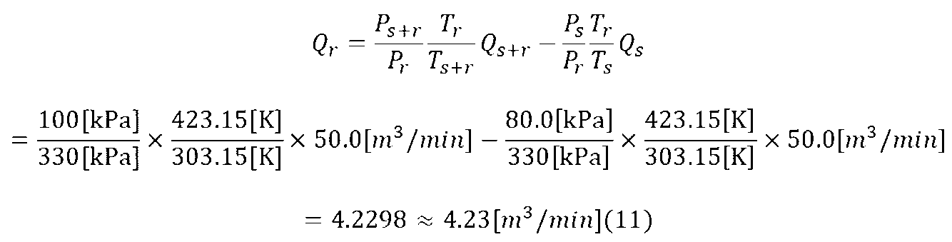
- the suction air pressure Ps is set to 80 [kPa] (atmospheric pressure near an altitude of 2000 m), and the suction pressure Ps+r is increased to 100 [kPa] using return air.
- Equation (12) shows that the return flow rate requires about 20% of the discharge flow rate, and as in Example 1, it can be used to determine the opening/closing amount of the adjustment valve 5 for adjusting the return flow rate in S204. can.
- the suction pressure can be stably increased by returning a portion of the discharged air to the buffer tank installed on the suction side. Furthermore, chattering of the regulating valve 5 attached to the air return pipe can be prevented.
Landscapes
- Engineering & Computer Science (AREA)
- Mechanical Engineering (AREA)
- General Engineering & Computer Science (AREA)
- Applications Or Details Of Rotary Compressors (AREA)
- Compressor (AREA)
Abstract
Description

この式(1)を戻り流量Qrの式にすると以下の通り式(2)に表すことができる。

ここで、吸込空気圧をQs=80kPa、吸込温度Ts=303.15K、密度ρs=0.92kg/m3、戻り空気圧力をPr=780kPa、戻り温度Tr=423.15K、密度ρr=6.43kg/m3、一段吸込み空気圧力をPs+r=100kPa、一段吸込流量Qs+r=50m3/min、吸込温度Ts+r=303.15K、密度ρs+r=1.15kg/m3とし、吸込空気量Qsと一段エアエンドの吸込空気量Qs+rが同等であると仮定すると、戻り流量Qrは以下の式(3)の通り計算することができる。

ここで、質量流量は温度によらず一定であることから、1段機吸込質量流量Gs+rは吐出質量流量Gdと同等である。戻り質量流量Grと1段機吸込質量流量Gs+rの比が、戻すべき流量であることがわかる。

式(4)より戻り質量流量Grは吐出質量流量Gdの内約20%を必要とすることが分かる。ここで、制御盤15は調整バルブ5の開閉量と戻り質量流量Grとを関連付けるテーブルまたは数式を図示しない記憶部に記憶しており、必要とする戻り質量流量Grをバッファタンク4に戻すために必要な調整バルブ5の開閉量を求めることができる。

実施例1と同様に、この式(5)を戻り流量Qrの式にすると以下の通りに式(6)で表すことができ、戻り流量Qrは以下の式(7)の通り計算することができる。式(8)により戻し流量は吐出流量の内約20%を必要とすることがわかり、実施例1と同様にS204における戻り流量の調整のための調整バルブ5の開閉量の決定に用いることができる。



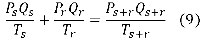
実施例1と同様に、この式(9)を戻り流量Qrの式にすると以下の通りに式(10)で表すことができ、戻り流量Qrは以下の式(11)の通り計算することができる。式(12)により戻し流量は吐出流量の内約20%を必要とすることがわかり、実施例1と同様にS204における戻り流量の調整のための調整バルブ5の開閉量の決定に用いることができる。

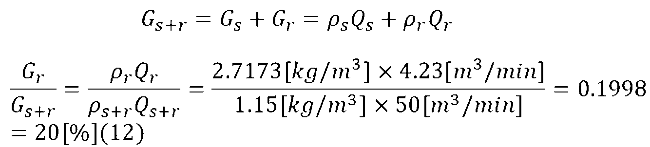
上記実施例1~3に示すように、単段機、2段機及び空気戻し位置に関係なく、計算により求められた量の吐出空気を戻すことで増圧させ、目標の吐出し空気圧力を維持することが可能である。
2 吸込みフィルタ
3 逆止弁
4 バッファタンク
5 流量調整バルブ
6 吸込み圧力センサ
7 圧縮機(一段機)
8 圧縮機(二段機)
9 オリフィス(減圧弁)
10 空気戻り配管
11 インタークーラ
12 アフタークーラ
13 吐出圧力センサ
14 吐出ポート
15 制御盤
16 中間圧力センサ
17 逆止弁
18 ブロー配管
Claims (13)
- 吸入口から空気吸入配管を介して吸入された吸入空気を圧縮する圧縮機と、
圧縮された前記空気を冷却する熱交換器と、
冷却された前記空気の内の一部を戻り空気として前記空気吸入配管に戻す空気戻り配管と、
前記空気戻り配管の所定に位置に設けられ、少なくとも前記戻り空気を一時的に貯めるバッファタンクと、
を有することを特徴とする空気圧縮装置。 - 前記バッファタンクは、
前記空気吸入配管から吸入された吸入空気と前記戻り空気とを一時的に貯めて、前記吸入空気と前記戻り空気とが混合された混合空気を前記圧縮機に送り込むことを特徴とする請求項1に記載の空気圧縮装置。 - 前記バッファタンクは、
前記圧縮機の入口側に設けられ、
前記熱交換器は、
前記圧縮機の出口側に設けられていることを特徴とする請求項1に記載の空気圧縮装置。 - 前記空気戻り配管の所定に位置に設けられた調整バルブと、
前記調整バルブを制御する制御盤と、を更に有し、
前記制御盤は、
前記調整バルブを開閉することにより前記バッファタンクへの前記戻り空気の流量を調整することを特徴とする請求項1に記載の空気圧縮装置。 - 前記空気戻り配管の所定に位置にオリフィスを更に有することを特徴とする請求項1に記載の空気圧縮装置。
- 前記空気吸入配管の所定の位置に設けられ、前記バッファタンクに貯められた前記戻り空気が前記空気吸入配管に逆流することを防ぐ逆止弁を更に有することを特徴とする請求項1に記載の空気圧縮装置。
- 空気吸入口から吸入された空気を圧縮する第1の圧縮機と、
前記第1の圧縮機で圧縮された空気をさらに圧縮する第2の圧縮機と、
前記第1の圧縮機により圧縮された前記空気を冷却する第1の熱交換器と、
前記第2の圧縮機により圧縮された前記空気を冷却する第2の熱交換器と、
前記第2の熱交換器により冷却された前記空気の内の一部を戻り空気として空気吸入側に戻す空気戻り配管と、
前記空気戻り配管に接続され、少なくとも前記戻り空気を一時的に貯めるバッファタンクと、
を有することを特徴とする空気圧縮装置。 - 前記バッファタンクは、
前記第1の圧縮機の入口側に設けられており、
前記空気吸入口から取り込まれた吸入空気と前記戻り空気とを一時的に貯めて、前記吸入空気と前記戻り空気とが混合された混合空気を前記第1の圧縮機に送り込むことを特徴とする請求項7に記載の空気圧縮装置。 - 前記バッファタンクの入口側に設けられ、前記戻り空気が前記空気吸入側に逆流することを防ぐ逆止弁を更に有することを特徴とする請求項8に記載の空気圧縮装置。
- 前記バッファタンクは、
前記第1の圧縮機と前記第2の圧縮機の間に設けられており、
前記戻り空気を一時的に貯めて、前記戻り空気を前記第2の圧縮機に送り込むことを特徴とする請求項7に記載の空気圧縮装置。 - 前記バッファタンクの出口側に設けられ、前記第1の熱交換器により冷却された前記空気が前記バッファタンクに逆流することを防ぐ逆止弁を更に有することを特徴とする請求項10に記載の空気圧縮装置。
- 前記空気戻り配管の所定に位置に設けられた調整バルブと、
前記調整バルブを制御する制御盤と、を更に有し、
前記制御盤は、
前記調整バルブを開閉することにより前記バッファタンクへの前記戻り空気の戻し量を調整することを特徴とする請求項7に記載の空気圧縮装置。 - 前記空気戻り配管の所定に位置に設けられ、前記戻り空気により前記調整バルブが劣化又は故障するのを防ぐオリフィスを更に有することを特徴とする請求項7に記載の空気圧縮装置。
Priority Applications (4)
| Application Number | Priority Date | Filing Date | Title |
|---|---|---|---|
| JP2024543679A JP7769136B2 (ja) | 2022-08-31 | 2022-08-31 | 空気圧縮装置 |
| PCT/JP2022/032716 WO2024047780A1 (ja) | 2022-08-31 | 2022-08-31 | 空気圧縮装置 |
| CN202280096304.5A CN119256162A (zh) | 2022-08-31 | 2022-08-31 | 空气压缩装置 |
| TW112125035A TWI867609B (zh) | 2022-08-31 | 2023-07-05 | 空氣壓縮裝置 |
Applications Claiming Priority (1)
| Application Number | Priority Date | Filing Date | Title |
|---|---|---|---|
| PCT/JP2022/032716 WO2024047780A1 (ja) | 2022-08-31 | 2022-08-31 | 空気圧縮装置 |
Publications (1)
| Publication Number | Publication Date |
|---|---|
| WO2024047780A1 true WO2024047780A1 (ja) | 2024-03-07 |
Family
ID=90098891
Family Applications (1)
| Application Number | Title | Priority Date | Filing Date |
|---|---|---|---|
| PCT/JP2022/032716 Ceased WO2024047780A1 (ja) | 2022-08-31 | 2022-08-31 | 空気圧縮装置 |
Country Status (4)
| Country | Link |
|---|---|
| JP (1) | JP7769136B2 (ja) |
| CN (1) | CN119256162A (ja) |
| TW (1) | TWI867609B (ja) |
| WO (1) | WO2024047780A1 (ja) |
Cited By (1)
| Publication number | Priority date | Publication date | Assignee | Title |
|---|---|---|---|---|
| CN119844352A (zh) * | 2025-02-08 | 2025-04-18 | 烟台东德实业有限公司 | 一种两级离子液封气体压缩机控制方法 |
Citations (3)
| Publication number | Priority date | Publication date | Assignee | Title |
|---|---|---|---|---|
| JPS60166785A (ja) * | 1984-02-10 | 1985-08-30 | Hitachi Ltd | 無給油式回転圧縮装置 |
| JP2005069013A (ja) * | 2003-08-22 | 2005-03-17 | Tokyo Electric Power Co Inc:The | ガス供給装置及びその制御方法 |
| US20190085854A1 (en) * | 2015-07-09 | 2019-03-21 | Nuovo Pignone Tecnologie Srl | Compressor system with a gas temperature control at the inlet of the anti-surge line and relevant method |
-
2022
- 2022-08-31 CN CN202280096304.5A patent/CN119256162A/zh active Pending
- 2022-08-31 WO PCT/JP2022/032716 patent/WO2024047780A1/ja not_active Ceased
- 2022-08-31 JP JP2024543679A patent/JP7769136B2/ja active Active
-
2023
- 2023-07-05 TW TW112125035A patent/TWI867609B/zh active
Patent Citations (3)
| Publication number | Priority date | Publication date | Assignee | Title |
|---|---|---|---|---|
| JPS60166785A (ja) * | 1984-02-10 | 1985-08-30 | Hitachi Ltd | 無給油式回転圧縮装置 |
| JP2005069013A (ja) * | 2003-08-22 | 2005-03-17 | Tokyo Electric Power Co Inc:The | ガス供給装置及びその制御方法 |
| US20190085854A1 (en) * | 2015-07-09 | 2019-03-21 | Nuovo Pignone Tecnologie Srl | Compressor system with a gas temperature control at the inlet of the anti-surge line and relevant method |
Cited By (1)
| Publication number | Priority date | Publication date | Assignee | Title |
|---|---|---|---|---|
| CN119844352A (zh) * | 2025-02-08 | 2025-04-18 | 烟台东德实业有限公司 | 一种两级离子液封气体压缩机控制方法 |
Also Published As
| Publication number | Publication date |
|---|---|
| JP7769136B2 (ja) | 2025-11-12 |
| TW202411537A (zh) | 2024-03-16 |
| TWI867609B (zh) | 2024-12-21 |
| CN119256162A (zh) | 2025-01-03 |
| JPWO2024047780A1 (ja) | 2024-03-07 |
Similar Documents
| Publication | Publication Date | Title |
|---|---|---|
| US20190011179A1 (en) | Boil-off gas supply device | |
| US12259165B2 (en) | Method for controlling suction pressure of a vapour compression system | |
| EP3913300B1 (en) | Method for starting cryogenic freezer and cryogenic freezer | |
| JP5261466B2 (ja) | Bog多段容積型圧縮機の運転制御方法 | |
| CN108547763B (zh) | 一种用于往复式压缩机闭式性能试验系统的进气调节装置 | |
| CN109964091A (zh) | 在气体旁通阀故障期间控制蒸气压缩系统的方法 | |
| US20170254338A1 (en) | Apparatus and method for surge prevention for centrifugal compressor | |
| JP7769136B2 (ja) | 空気圧縮装置 | |
| KR20160022510A (ko) | 원심압축기의 서지 방지 장치 및 방법 | |
| US6793456B2 (en) | Turbo-compressor and capacity control method thereof | |
| JP7025272B2 (ja) | ガス供給装置及びその停止制御方法 | |
| EP2392825B1 (en) | Method for controlling the operation of a multistage boil-off gas (BOG) compressor | |
| US11768014B2 (en) | Surge protection for a multistage compressor | |
| JP4240589B2 (ja) | 低温ガスターボ圧縮機の運転開始方法 | |
| JP2002213366A (ja) | Bog圧縮機の起動時の運転制御方法 | |
| CN212107873U (zh) | 一种适用于液化天然气接收站的再冷凝器 | |
| CN114364934B (zh) | 室外单元以及冷冻循环装置 | |
| JPH08284839A (ja) | 低温ガス圧縮機の運転方法および制御装置 | |
| JP3384894B2 (ja) | ターボ圧縮機の容量制御方法 | |
| JP4134373B2 (ja) | 低温ガス用レシプロ圧縮機の吸引ヘッダー母管の冷却設備 | |
| JP2001082345A (ja) | 無給油式可変容量圧縮機 | |
| JP2017172690A (ja) | 低温液化ガス貯蔵設備 | |
| JP2024024276A (ja) | 圧縮機の減圧装置および圧縮機の減圧方法 | |
| JP4881007B2 (ja) | 圧縮機のアンロード運転制御方法 | |
| CN119982470A (zh) | 一种超临界co2压缩机自动控制方法 |
Legal Events
| Date | Code | Title | Description |
|---|---|---|---|
| 121 | Ep: the epo has been informed by wipo that ep was designated in this application |
Ref document number: 22957379 Country of ref document: EP Kind code of ref document: A1 |
|
| ENP | Entry into the national phase |
Ref document number: 2024543679 Country of ref document: JP Kind code of ref document: A |
|
| WWE | Wipo information: entry into national phase |
Ref document number: 18863460 Country of ref document: US |
|
| WWE | Wipo information: entry into national phase |
Ref document number: 202280096304.5 Country of ref document: CN |
|
| WWE | Wipo information: entry into national phase |
Ref document number: 202417093194 Country of ref document: IN |
|
| WWP | Wipo information: published in national office |
Ref document number: 202280096304.5 Country of ref document: CN |
|
| NENP | Non-entry into the national phase |
Ref country code: DE |
|
| 122 | Ep: pct application non-entry in european phase |
Ref document number: 22957379 Country of ref document: EP Kind code of ref document: A1 |