WO2024042860A1 - Disassembly method for two-stage cold head, and displacer removal jig - Google Patents
Disassembly method for two-stage cold head, and displacer removal jig Download PDFInfo
- Publication number
- WO2024042860A1 WO2024042860A1 PCT/JP2023/024273 JP2023024273W WO2024042860A1 WO 2024042860 A1 WO2024042860 A1 WO 2024042860A1 JP 2023024273 W JP2023024273 W JP 2023024273W WO 2024042860 A1 WO2024042860 A1 WO 2024042860A1
- Authority
- WO
- WIPO (PCT)
- Prior art keywords
- displacer
- stage
- cold head
- cylinder
- stage displacer
- Prior art date
Links
- 238000000034 method Methods 0.000 title claims abstract description 38
- 238000000605 extraction Methods 0.000 claims description 33
- 239000007789 gas Substances 0.000 description 26
- 238000001816 cooling Methods 0.000 description 15
- 238000010586 diagram Methods 0.000 description 12
- 238000012423 maintenance Methods 0.000 description 10
- 239000000463 material Substances 0.000 description 8
- 238000006243 chemical reaction Methods 0.000 description 7
- RYGMFSIKBFXOCR-UHFFFAOYSA-N Copper Chemical compound [Cu] RYGMFSIKBFXOCR-UHFFFAOYSA-N 0.000 description 4
- 229910052802 copper Inorganic materials 0.000 description 4
- 239000010949 copper Substances 0.000 description 4
- 238000012986 modification Methods 0.000 description 3
- 230000004048 modification Effects 0.000 description 3
- 230000000737 periodic effect Effects 0.000 description 3
- 230000002159 abnormal effect Effects 0.000 description 2
- 238000013459 approach Methods 0.000 description 1
- 229910052797 bismuth Inorganic materials 0.000 description 1
- JCXGWMGPZLAOME-UHFFFAOYSA-N bismuth atom Chemical compound [Bi] JCXGWMGPZLAOME-UHFFFAOYSA-N 0.000 description 1
- 230000007423 decrease Effects 0.000 description 1
- 238000013461 design Methods 0.000 description 1
- 230000000694 effects Effects 0.000 description 1
- 239000008187 granular material Substances 0.000 description 1
- 239000001307 helium Substances 0.000 description 1
- 229910052734 helium Inorganic materials 0.000 description 1
- SWQJXJOGLNCZEY-UHFFFAOYSA-N helium atom Chemical compound [He] SWQJXJOGLNCZEY-UHFFFAOYSA-N 0.000 description 1
- 239000007788 liquid Substances 0.000 description 1
- 230000007774 longterm Effects 0.000 description 1
- 239000002184 metal Substances 0.000 description 1
- 229910052751 metal Inorganic materials 0.000 description 1
- 239000007769 metal material Substances 0.000 description 1
- NJPPVKZQTLUDBO-UHFFFAOYSA-N novaluron Chemical compound C1=C(Cl)C(OC(F)(F)C(OC(F)(F)F)F)=CC=C1NC(=O)NC(=O)C1=C(F)C=CC=C1F NJPPVKZQTLUDBO-UHFFFAOYSA-N 0.000 description 1
- 239000003507 refrigerant Substances 0.000 description 1
- 238000005057 refrigeration Methods 0.000 description 1
- 229910001220 stainless steel Inorganic materials 0.000 description 1
- 239000010935 stainless steel Substances 0.000 description 1
- 239000011232 storage material Substances 0.000 description 1
- 239000000725 suspension Substances 0.000 description 1
- 230000001360 synchronised effect Effects 0.000 description 1
- 238000003466 welding Methods 0.000 description 1
Images


Classifications
-
- F—MECHANICAL ENGINEERING; LIGHTING; HEATING; WEAPONS; BLASTING
- F25—REFRIGERATION OR COOLING; COMBINED HEATING AND REFRIGERATION SYSTEMS; HEAT PUMP SYSTEMS; MANUFACTURE OR STORAGE OF ICE; LIQUEFACTION SOLIDIFICATION OF GASES
- F25B—REFRIGERATION MACHINES, PLANTS OR SYSTEMS; COMBINED HEATING AND REFRIGERATION SYSTEMS; HEAT PUMP SYSTEMS
- F25B9/00—Compression machines, plants or systems, in which the refrigerant is air or other gas of low boiling point
Definitions
- the present invention relates to a two-stage cold head disassembly method and a displacer extraction jig.
- a mounting structure provided with a sleeve in order to mount a cryogenic refrigerator to a cryogenic vacuum container such as a cryostat.
- An object to be cooled such as a superconducting coil, is housed in the cryogenic vacuum vessel, and this object is in thermal contact with the end of the sleeve.
- the cold head of the cryogenic refrigerator is installed inside the sleeve, and cools the object through the sleeve.
- the cold head is somewhat movable relative to the sleeve so that thermal contact between the cold head and the sleeve can be broken.
- the cold head is heated to a temperature convenient for maintenance work, such as room temperature, while the object to be cooled can be maintained at an extremely low temperature. There is no need to heat up and re-cool the object to be cooled for maintenance of the cryogenic refrigerator, thereby reducing the time required for maintenance of the cryogenic refrigerator.
- the cold head is disassembled during maintenance.
- a displacer assembly consisting of a single-stage displacer and a two-stage displacer is withdrawn from the cold head.
- the displacer assembly thus removed is subjected to maintenance such as replacing consumable parts, or replaced with a new one, and the cold head is reassembled.
- One exemplary object of an embodiment of the present invention is a method for disassembling a two-stage cold head that makes it possible to take out a two-stage displacer left in the two-stage cold head, and a displacer extraction jig suitable for this method.
- Our goal is to provide the following.
- a method for disassembling a two-stage cold head includes attaching a displacer removal jig to the two-stage displacer left in the two-stage cold head, and removing the two-stage displacer from the two-stage cold head. operating the displacer extraction jig so that it is pulled out.
- a method for disassembling a two-stage coldhead includes a displacer assembly including a first-stage displacer and a second-stage displacer, and a displacer drive shaft coupled to the first-stage displacer.
- the disassembly method includes attaching a displacer extraction jig to the displacer drive shaft and operating the displacer extraction jig such that the displacer assembly is withdrawn from the two-stage cold head.
- the displacer extraction jig includes a gripper that can engage the two-stage displacer of the two-stage cold head, and a lifter that is configured to raise and lower the gripper.
- the present invention it is possible to provide a method for disassembling a two-stage cold head that makes it possible to take out the two-stage displacer left in the two-stage cold head, and a displacer extraction jig suitable for this method.
- FIG. 1 is a diagram schematically showing a cryogenic refrigerator according to an embodiment.
- FIG. 1 is a diagram schematically showing a cryogenic refrigerator according to an embodiment.
- FIG. 3 is an exploded perspective view schematically showing an example of a connection structure of a single-stage displacer and a two-stage displacer in the displacer assembly shown in FIGS. 1 and 2.
- FIG. FIGS. 4(a) to 4(c) are diagrams schematically showing a displacer extraction jig according to an embodiment.
- FIGS. 5A and 5B are diagrams schematically showing a displacer extraction jig according to an embodiment. It is a schematic diagram showing a method of disassembling a cold head according to an embodiment. It is a schematic diagram showing a method of disassembling a cold head according to an embodiment.
- FIGS. 8A and 8B are diagrams schematically showing other examples of the gripping tool of the displacer extraction jig according to the embodiment.
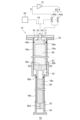
- FIG. 1 and 2 are diagrams schematically showing a cryogenic refrigerator 10 according to an embodiment.
- FIG. 1 shows the external appearance of the cryogenic refrigerator 10
- FIG. 2 shows the internal structure of the cryogenic refrigerator 10.
- the cryogenic refrigerator 10 is, for example, a two-stage Gifford-McMahon (GM) refrigerator.
- GM Gifford-McMahon
- the cryogenic refrigerator 10 includes a compressor 12 and a two-stage cold head 14.
- the compressor 12 is configured to recover the working gas of the cryogenic refrigerator 10 from the cold head 14, pressurize the recovered working gas, and supply the working gas to the cold head 14 again.
- Cold head 14 is also called an expander.
- the working gas also referred to as refrigerant gas, is typically helium gas, although other suitable gases may be used.
- the pressure of the working gas supplied from the compressor 12 to the cold head 14 and the pressure of the working gas recovered from the cold head 14 to the compressor 12 are both significantly higher than atmospheric pressure, and are respectively at the first high pressure and It can be called the second high pressure.
- the first high pressure and the second high pressure are also simply referred to as high pressure and low pressure, respectively.
- the high pressure is for example 2-3 MPa.
- the low pressure is, for example, 0.5 to 1.5 MPa, for example about 0.8 MPa.
- the direction of flow of the working gas is indicated by arrows.
- the cold head 14 includes a refrigerator cylinder 16 and a displacer assembly 18.
- the refrigerator cylinder 16 guides the linear reciprocating motion of the displacer assembly 18, and forms an expansion chamber (32, 34) for working gas between the refrigerator cylinder 16 and the displacer assembly 18.
- the cold head 14 includes a pressure switching valve 40 that determines the timing at which the intake of working gas into the expansion chamber starts and the timing at which the exhaust of the working gas from the expansion chamber starts.
- the side near the top dead center of the reciprocating motion of the displacer in the axial direction is referred to as "upper”, and the side closer to the bottom dead center is referred to as “lower”. ”.
- the top dead center is the position of the displacer where the volume of the expansion space is maximum
- the bottom dead center is the position of the displacer where the volume of the expansion space is the minimum.
- a temperature gradient occurs in which the temperature decreases from the upper side to the lower side in the axial direction, so the upper side can also be called the high temperature side and the lower side can also be called the low temperature side.
- the refrigerator cylinder 16 has a first-stage cylinder 16a and a second-stage cylinder 16b.
- the first-stage cylinder 16a and the second-stage cylinder 16b are, for example, members having a cylindrical shape, and the second-stage cylinder 16b has a smaller diameter than the first-stage cylinder 16a.
- the first-stage cylinder 16a and the second-stage cylinder 16b are arranged coaxially, and the lower end of the first-stage cylinder 16a is rigidly connected to the upper end of the second-stage cylinder 16b.
- the displacer assembly 18 includes a single-stage displacer 18a and a two-stage displacer 18b that are connected to each other and move together.
- the first-stage displacer 18a and the second-stage displacer 18b are, for example, members having a cylindrical shape, and the second-stage displacer 18b has a smaller diameter than the first-stage displacer 18a.
- the first stage displacer 18a and the second stage displacer 18b are arranged coaxially.
- the first stage displacer 18a is housed in the first stage cylinder 16a, and the second stage displacer 18b is housed in the second stage cylinder 16b.
- the first-stage displacer 18a can reciprocate in the axial direction along the first-stage cylinder 16a, and the second-stage displacer 18b can reciprocate in the axial direction along the second-stage cylinder 16b.
- the single-stage displacer 18a accommodates the first regenerator 26.
- the first regenerator 26 is formed by filling the cylindrical main body of the one-stage displacer 18a with a wire mesh made of copper or other appropriate first regenerator material, for example.
- the upper lid part and the lower lid part of the single-stage displacer 18a may be provided as separate members from the main body part of the single-stage displacer 18a, and the upper lid part and the lower lid part of the single-stage displacer 18a are attached to the main body by an appropriate means such as fastening or welding. , and thereby the first regenerator material may be accommodated in the one-stage displacer 18a.
- the two-stage displacer 18b accommodates the second regenerator 28.
- the second regenerator 28 is constructed by filling the cylindrical main body of the two-stage displacer 18b with a non-magnetic regenerator material such as bismuth, a magnetic regenerator material such as HoCu 2 , or any other appropriate second regenerator material. is formed by.
- the second cold storage material may be formed into granules.
- the upper lid part and the lower lid part of the two-stage displacer 18b may be provided as separate members from the main body of the two-stage displacer 18b, and the upper lid part and the lower lid part of the two-stage displacer 18b may be fastened, welded, or otherwise
- the second regenerator material may be fixed to the main body by means such that the second regenerator material is accommodated in the two-stage displacer 18b.
- the displacer assembly 18 forms an indoor chamber 30, a first expansion chamber 32, and a second expansion chamber 34 inside the refrigerator cylinder 16.
- the cold head 14 comprises a first cooling stage 33 and a second cooling stage 35.
- the indoor greenhouse 30 is formed between the upper lid part of the single-stage displacer 18a and the upper part of the single-stage cylinder 16a.
- the first expansion chamber 32 is formed between the lower lid portion of the single-stage displacer 18a and the first cooling stage 33.
- the second expansion chamber 34 is formed between the lower lid portion of the two-stage displacer 18b and the second cooling stage 35.
- the first cooling stage 33 is fixed to the lower part of the first stage cylinder 16a so as to surround the first expansion chamber 32
- the second cooling stage 35 is fixed to the lower part of the second stage cylinder 16b so as to surround the second expansion chamber 34.
- the first cooling stage 33 and the second cooling stage 35 are formed of, for example, pure copper (eg, oxygen-free copper, tough pitch copper, etc.) or other high heat conductive metal.
- the first regenerator 26 is connected to the indoor greenhouse 30 through a working gas passage 36a formed in the upper lid of the single-stage displacer 18a, and is first expanded through a working gas passage 36b formed in the lower lid of the single-stage displacer 18a. It is connected to the chamber 32.
- the second regenerator 28 is connected to the first regenerator 26 through a working gas passage 36c formed from the lower lid of the single-stage displacer 18a to the upper lid of the second-stage displacer 18b. Further, the second regenerator 28 is connected to the second expansion chamber 34 through a working gas flow path 36d formed in the lower lid portion of the two-stage displacer 18b.
- the working gas flow between the first expansion chamber 32, the second expansion chamber 34, and the indoor greenhouse 30 is not limited to the clearance between the refrigerator cylinder 16 and the displacer assembly 18;
- a first seal 38a and a second seal 38b may be provided to guide the liquid to the vessel 28.
- the first seal 38a may be attached to the upper lid portion of the single-stage displacer 18a so as to be disposed between the single-stage displacer 18a and the single-stage cylinder 16a.
- the second seal 38b may be attached to the upper lid portion of the two-stage displacer 18b so as to be disposed between the two-stage displacer 18b and the two-stage cylinder 16b.
- the cold head 14 includes a refrigerator housing 20 that houses a pressure switching valve 40.
- Refrigerator housing 20 is coupled to refrigerator cylinder 16, thereby forming an airtight container housing pressure switching valve 40 and displacer assembly 18.
- Refrigerator housing 20 and refrigerator cylinder 16 are formed of a metallic material, such as stainless steel, or other suitable high-strength material so as to be airtight containers and withstand internal and external pressure differences.
- the pressure switching valve 40 includes a high pressure valve 40a and a low pressure valve 40b, and is configured to generate periodic pressure fluctuations within the refrigerator cylinder 16.
- a working gas discharge port of the compressor 12 is connected to the indoor room 30 via a high pressure valve 40a, and a working gas inlet of the compressor 12 is connected to the indoor room 30 via a low pressure valve 40b.
- High pressure valve 40a and low pressure valve 40b are configured to open and close selectively and alternately (ie, when one is open, the other is closed).
- the pressure switching valve 40 may take the form of a rotary valve. That is, the pressure switching valve 40 may be configured such that the high pressure valve 40a and the low pressure valve 40b are alternately opened and closed by rotational sliding of the valve disk with respect to a stationary valve body. In that case, the expander motor 42 may be coupled to the pressure switching valve 40 to rotate the valve disc of the pressure switching valve 40.
- the pressure switching valve 40 is arranged such that the valve rotation axis is coaxial with the rotation axis of the expander motor 42.
- the high pressure valve 40a and the low pressure valve 40b may each be individually controllable valves, and in that case, the pressure switching valve 40 does not need to be connected to the expander motor 42.
- the cold head 14 includes an expander motor 42 and a motion conversion mechanism 43.
- the expander motor 42 is a drive source that drives the cold head 14, and is, for example, an electric motor driven by three-phase alternating current. Expander motor 42 is attached to refrigerator housing 20.
- the motion conversion mechanism 43 like the pressure switching valve 40, is housed in the refrigerator housing 20.
- the expander motor 42 is connected to a displacer drive shaft 44 via a motion conversion mechanism 43 such as a Scotch yoke mechanism.
- the motion conversion mechanism 43 converts the rotational motion output by the expander motor 42 into linear reciprocating motion of the displacer drive shaft 44.
- the displacer drive shaft 44 extends from the motion conversion mechanism 43 into the indoor greenhouse 30, and is fixed to the upper lid portion of the single-stage displacer 18a.
- the rotation of the expander motor 42 is converted by the motion converting mechanism 43 into an axial reciprocating motion of the displacer drive shaft 44, and the displacer assembly 18 linearly reciprocates in the axial direction within the refrigerator cylinder 16.
- the cryogenic refrigerator 10 is configured such that when the compressor 12 and the expander motor 42 are operated, periodic volume fluctuations occur in the first expansion chamber 32 and the second expansion chamber 34, and the working gas is synchronized with the periodic volume fluctuations. This causes pressure fluctuations.
- the low pressure valve 40b is closed and the high pressure valve 40a is opened, so that high pressure working gas flows from the compressor 12 into the indoor room 30 through the high pressure valve 40a, passes through the first regenerator 26, and then flows into the room temperature chamber 30 through the first regenerator 26. It is supplied to the first expansion chamber 32 and then to the second expansion chamber 34 through the second regenerator 28 .
- the pressure in the first expansion chamber 32 and the second expansion chamber 34 is increased from low pressure to high pressure.
- the displacer assembly 18 is moved upward from the bottom dead center to the top dead center, and the volumes of the first expansion chamber 32 and the second expansion chamber 34 are increased.
- the high pressure valve 40a closes, the intake stroke ends.
- the high-pressure valve 40a closes and the low-pressure valve 40b opens, thereby opening the high-pressure first expansion chamber 32 and the second expansion chamber 34 to the low-pressure working gas inlet of the compressor 12.
- the working gas expands in the first expansion chamber 32 and the second expansion chamber 34, and as a result, the working gas with a low pressure is transferred from the first expansion chamber 32 and the second expansion chamber 34 to the first regenerator 26 and the second expansion chamber 34. It is discharged to the indoor greenhouse 30 through the regenerator 28.
- the displacer assembly 18 is moved downward from the top dead center to the bottom dead center, and the volumes of the first expansion chamber 32 and the second expansion chamber 34 are reduced.
- Working gas is recovered from the cold head 14 to the compressor 12 through the low pressure valve 40b. When the low pressure valve 40b closes, the exhaust process ends.
- a refrigeration cycle such as a GM cycle is configured, and the first cooling stage 33 and the second cooling stage 35 are cooled to a desired extremely low temperature.
- the first cooling stage 33 may be cooled to a first cooling temperature ranging from about 30K to about 70K, for example.
- the second cooling stage 35 may be cooled to a second cooling temperature (eg, about 1K to about 4K) lower than the first cooling temperature.
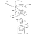
- FIG. 3 is an exploded perspective view schematically showing an example of the connection structure of the single-stage displacer 18a and the two-stage displacer 18b in the displacer assembly 18 shown in FIGS. 1 and 2.
- a cylindrical recess 46 is provided at the low temperature end (lower lid portion in FIGS. 1 and 2) of the single-stage displacer 18a, coaxially with the central axis of the single-stage displacer 18a.
- the recess 46 has a small diameter part 46a on the upper side and a large diameter part 46b on the lower side.
- a single-stage displacer pin hole 48a is further provided at the low-temperature end of the single-stage displacer 18a, passing through the first-stage displacer 18a and the small diameter portion 46a of the recess 46 in the radial direction and perpendicular to the central axis of the single-stage displacer 18a.
- a cylindrical recess 47 (see FIG. 6) is provided at the high temperature end (upper lid portion in FIGS. 1 and 2) of the two-stage displacer 18b coaxially with the central axis of the two-stage displacer 18b.
- the high-temperature end of the two-stage displacer 18b is further provided with a two-stage displacer pin hole 48b that extends through the two-stage displacer 18b and the recess 47 in the radial direction and perpendicular to the central axis of the two-stage displacer 18b.
- a short cylindrical connecting body 50 is provided between the first stage displacer 18a and the second stage displacer 18b.
- a first pin hole 50a is provided at one end (the upper end in FIG. 3) of the connecting body 50 and extends through the connecting body 50 in the radial direction perpendicular to the central axis of the connecting body 50.
- a second pin hole 50b is provided at the lower end in FIG. 3, which extends through the connecting body 50 in the radial direction and perpendicularly to the central axis thereof.
- the first pin hole 50a and the second pin hole 50b are provided at different positions along the central axis of the connecting body 50 so as to be perpendicular to each other.
- One end of the connecting body 50 can be inserted into the small diameter portion 46a of the recess 46 provided in the single-stage displacer 18a, and when the connecting body 50 is inserted, the first pin hole 50a communicates with the single-stage displacer pin hole 48a. do.
- the first connecting pin 52a is inserted into the first stage displacer pin hole 48a and the first pin hole 50a, thereby connecting the connecting body 50 with the first stage displacer 18a.
- the other end of the connecting body 50 can be inserted into the recess of the two-stage displacer 18b, and when the connecting body 50 is inserted, the second pin hole 50b communicates with the two-stage displacer pin hole 48b.
- the second connecting pin 52b is inserted into the two-stage displacer pin hole 48b and the second pin hole 50b, thereby connecting the connecting body 50 with the two-stage displacer 18b. In this way, the first stage displacer 18a and the second stage displacer 18b are connected via the connecting body 50.
- connection structure between the single-stage displacer 18a and the two-stage displacer 18b may have other configurations.
- the connecting body 50 it is not essential to use the connecting body 50, and the two-stage displacer 18b may be inserted into the recess 46 of the one-stage displacer 18a, and the one-stage displacer 18a and the second-stage displacer 18b may be connected with one connecting pin.
- the cold head 14 may be disassembled for maintenance of the cryogenic refrigerator 10.
- the fastening between the refrigerator housing 20 and the refrigerator cylinder 16 is released, and the refrigerator housing 20 is lifted from the refrigerator cylinder 16.
- the displacer assembly 18 is also raised relative to the refrigerator cylinder 16 along with the displacer drive mechanism, such as the expander motor 42 and the motion conversion mechanism 43 within the refrigerator housing 20 .
- the first stage displacer 18a and the second stage displacer 18b are pulled out from the first stage cylinder 16a and the second stage cylinder 16b, respectively, and finally the refrigerator housing 20 and the displacer assembly 18 are removed from the cold head 14.
- Only the first-stage displacer 18a may be pulled out, and the second-stage displacer 18b may be left behind in the second-stage cylinder 16b. If the two-stage displacer 18b remains in the cold head 14, maintenance of the cold head 14 cannot be completed, and operation of the cryogenic refrigerator 10 cannot be restarted.
- a method of disassembling the cold head 14 that can be easily performed on site is proposed.
- the two-stage displacer 18b remaining in the cold head 14 can be taken out using a displacer removal jig 60, which will be described below.
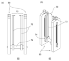
- FIGS. 4(a) to 4(c) are diagrams schematically showing a displacer extraction jig 60 according to an embodiment.
- 4A shows a front view of the displacer removal jig 60
- FIG. 4B shows a side view of the displacer removal jig 60
- FIG. 4C shows a partially cutaway perspective view of the displacer removal jig 60. It will be done.
- the displacer extraction jig 60 includes a gripping tool 70 that can engage with the two-stage displacer 18b of the cold head 14, and a lifter 80 configured to raise and lower the gripping tool 70.
- the gripping tool 70 includes two vertical rods 72 that extend parallel to each other in the vertical direction (vertical direction in the figure), and a horizontal rod that extends in the horizontal direction that is perpendicular to the vertical direction and supports these vertical rods 72.
- a suspension rod 74 is provided.
- Each vertical rod 72 includes a base 72a and a tip 72b.
- the longitudinal rod 72 has a rectangular cross-section in this example, but may have other cross-sectional shapes.
- the base 72a of the vertical rod 72 has a ring-like shape with a through hole in its center that receives the horizontal rod 74.
- the vertical rod 72 is connected to the horizontal rod 74 so as to be movable in the horizontal direction with respect to the horizontal rod 74.
- the horizontal rod 74 has a circular cross section
- the through hole in the base 72a of the vertical rod 72 also has the same circular cross section, so that the vertical rod 72 can rotate around the horizontal rod 74. It's also possible.
- the horizontal rod 74 may have another cross-sectional shape such as a rectangular cross-section, and the through hole in the base 72a of the vertical rod 72 may also have a corresponding shape.
- the gripping tool 70 includes a gripping pin 76 having a shape that can be inserted into the two-stage displacer pin hole 48b. Therefore, the grip pin 76 has a shape corresponding to the two-stage displacer pin hole 48b. For example, if the two-stage displacer pin hole 48b is a round hole, the grip pin 76 is a cylindrical pin correspondingly.
- a gripping pin 76 is provided on each longitudinal rod 72, that is, in this embodiment, the gripping tool 70 is provided with two gripping pins 76.
- a gripping pin hole into which a gripping pin 76 is inserted is provided at the tip 72b of the vertical rod 72. This gripping pin hole passes through the tip 72b of the vertical rod 72 in the horizontal direction. The grip pin 76 is attached to the vertical rod 72 by being inserted into the grip pin hole.
- the gripping pin 76 is replaceable. That is, the gripping pin 76 is removably attached to the vertical rod 72. If necessary, pull out the attached grip pin 76 from the grip pin hole, insert another grip pin 76 (for example, a new grip pin 76) into the grip pin hole, and attach it to the vertical rod 72. I can do it.
- a large force acts on the gripping pin 76, and the gripping pin 76 may be deformed.
- the same displacer extraction jig 60 can be used for the next cold head disassembly operation.
- the lifter 80 includes a support body 82 and a feed screw mechanism 84 built into the support body 82.
- the support body 82 consists of two support rods extending parallel to each other in the longitudinal direction, and each support rod includes a base portion 82a and a tip portion 82b. Each support rod is provided with a slit 82c extending vertically from the base 82a to the tip 82b.
- the feed screw mechanism 84 includes a feed screw 86 that is rotatably supported by the support 82 and a nut portion 88 that is screwed into the feed screw 86.
- the nut portion 88 is supported by the rotation of the feed screw 86 with respect to the support 82.
- the body 82 is configured to move relative to the body 82.
- one support rod of the support body 82 is cut away and illustrated on a plane passing through the center axis of the feed screw 86 and the center axis of the horizontal rod 74 for ease of understanding. There is.
- the feed screw 86 is rotatably supported by the tip end 82b of the support rod, and extends vertically within the slit 82c.
- a screw head 86a of the feed screw 86 is provided on the tip 82b of the support rod, and the feed screw mechanism 84 can be operated by an operator rotating the screw head 86a.
- a threaded portion 86b of the feed screw 86 is arranged within the slit 82c.
- the nut portions 88 are provided at both ends of the horizontal rod 74 and are a part of the horizontal rod 74.
- the feed screw 86 is screwed into the nut portion 88 at the tip of the threaded portion 86b of the feed screw 86 adjacent to the base portion 82a of the support rod.
- the nut portion 88 is disposed in the slit 82c of the support body 82 in a state where it is screwed with the feed screw 86, and is movable in the vertical direction along the slit 82c by rotation of the feed screw 86.
- the gripper 70 is connected to the nut part 88 so as to move together with the nut part 88.
- FIGS. 5(a) and 5(b) are diagrams schematically showing a displacer extraction jig 60 according to an embodiment.
- FIG. 5A shows a front view of the displacer removal jig 60
- FIG. 5B shows a perspective view of the displacer removal jig 60.
- 4(a) to 4(c) show the unfolded state of the displacer extracting jig 60
- FIGS. 5(a) and 5(b) show the displacer extracting jig 60 in the stored state. is shown.
- the vertical rod 72 of the gripper 70 is connected to the horizontal rod as compared to the deployed state shown in FIGS. 4(a) to 4(c). It is rotated about 180 degrees around 74 and folded into a lifter 80.
- the displacer extraction jig 60 according to the embodiment is foldable.
- the length of the displacer extraction jig 60 in the stored state in the vertical direction is approximately half that of the displacer extraction jig 60 in the expanded state. In this way, by making the displacer removal jig 60 compact by folding it, the storage space for the displacer removal jig 60 can be reduced.
- displacer removal jig 60 may be disassembled and stored, such as by removing the gripper 70 from the lifter 80.
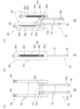
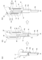
- FIG. 6 is a schematic diagram showing a method of disassembling the cold head 14 according to the embodiment.
- the refrigerator cylinder 16 is shown cut along a plane including its central axis.
- This disassembly method starts with only the second-stage displacer 18b left behind in the second-stage cylinder 16b of the refrigerator cylinder 16, as shown on the left side of FIG. 6 (S10).
- This state is a result of the connecting portion between the first-stage displacer 18a and the second-stage displacer 18b being damaged and only the first-stage displacer 18a being pulled out from the first-stage cylinder 16a, as described above.
- the second connecting pin 52b (see FIG. 3), which was inserted into the second-stage displacer pin hole 48b of the second-stage displacer 18b, breaks when the connecting body 50 is pulled up together with the first-stage displacer 18a, and It is assumed that the displacer pin has fallen out from the displacer pin hole 48b. However, if the second connecting pin 52b remains in the second stage displacer pin hole 48b, the second connecting pin 52b is removed from the second stage displacer pin hole 48b at this stage.
- a displacer extraction jig 60 is prepared, and as described below, the displacer extraction jig 60 is attached to the remaining two-stage displacer 18b (S11).
- the support 82 of the displacer removal jig 60 is placed on the refrigerator cylinder 16.
- the refrigerator cylinder 16 includes a cylinder flange 17 at the upper end of the first-stage cylinder 16a (the end opposite to the second-stage cylinder 16b).
- the cylinder flange 17 extends radially outward from the upper end of the first-stage cylinder 16a.
- the support body 82 ie the bases 82a of the two support rods, is placed on the upper surface of the cylinder flange 17.
- the support body 82 is merely placed on the cylinder flange 17, and the support body 82 is not fixed to the cylinder flange 17. However, if necessary, the support body 82 may be fixed to the cylinder flange 17 by an appropriate method such as screwing. Further, instead of placing or fixing the support body 82 on the cylinder flange 17, pedestals for placing or fixing the support body 82 may be prepared on both sides of the refrigerator cylinder 16, and the support body 82 is supported on the pedestal. The body 82 may be mounted or fixed.
- the displacer extraction jig 60 is in the unfolded state, and the vertical rod 72 extends from the horizontal rod 74 toward the opposite side (lower side in the figure) from the tip end 82b of the support rod.
- the distance between the vertical rods 72 is adjusted in advance by sliding the vertical rods 72 relative to the horizontal rods 74.
- the interval between the vertical rods 72 is adjusted to be smaller than the inner diameter of the first stage cylinder 16a.
- the interval between the vertical rods 72 is such that the interval between the tips of the gripping pins 76 is larger than the outer diameter of the two-stage displacer 18b in order to avoid interference between the gripping pin 76 attached to the tip 72b and the two-stage displacer 18b. It is adjusted as follows.
- the vertical rod 72 is inserted into the first stage cylinder 16a.
- the vertical length of the vertical rod 72 is set to be approximately the same length as the depth of the first-stage cylinder 16a. Therefore, when the support body 82 is placed on the cylinder flange 17, the gripping pin 76 attached to the vertical rod 72 is placed at the bottom of the first stage cylinder 16a, and the second stage at the upper end of the remaining two stage displacer 18b. It will be located near the displacer pin hole 48b.
- the vertical alignment of the gripping pin 76 and the two-stage displacer pin hole 48b is made possible by rotating the feed screw 86 and finely adjusting the position of the nut portion 88, that is, the horizontal rod 74, in the vertical direction. Furthermore, circumferential alignment of the gripping pin 76 and the two-stage displacer pin hole 48b is made possible by moving the displacer extraction jig 60 on the cylinder flange 17. In this way, the positional relationship between the gripping pins 76 and the second-stage displacer pin hole 48b can be adjusted such that the two gripping pins 76 are located on both sides of the second-stage displacer pin hole 48b.
- the two gripping pins 76 are inserted into the second stage displacer pin holes. 48b.
- the gripper 70 is engaged with the two-stage displacer 18b, and the displacer extraction jig 60 is attached to the two-stage displacer 18b.
- the tips 72b of the two vertical rods 72 to which the gripping pins 76 are attached may be inserted into the recesses 47 of the two-stage displacer 18b. Then, the vertical rods 72 may be slid with respect to the horizontal rods 74 so as to widen the interval between the vertical rods 72, and the grip pins 76 may be inserted from the inside into the two-stage displacer pin holes 48b.
- the displacer extraction jig 60 is operated so that the two-stage displacer 18b is pulled out from the refrigerator cylinder 16 (S12). Specifically, by rotating the feed screw 86 (arrow 90), the nut portion 88, that is, the horizontal rod 74 is raised (arrow 91), thereby moving the two-stage displacer 18b gripped by the gripper 70 into two stages. It can be pulled out from the cylinder 16b.
- the gripping tool 70 can be pulled up together with the two-stage cylinder 16b. Thereafter, by lifting the displacer removal jig 60 itself from the cylinder flange 17, the two-stage cylinder 16b can be pulled out and removed from the refrigerator cylinder 16.
- Another functioning displacer assembly 18 eg, a new displacer assembly 18
- a method for disassembling the cold head 14 using the displacer extracting jig 60 is provided to take out the two-stage displacer 18b left in the cold head 14 by using the displacer extracting jig 60. can be provided. Even if the two-stage displacer 18b is left behind in the refrigerator cylinder 16, maintenance of the cold head 14 can be completed on-site without removing the entire cold head 14 from the cryogenic equipment to which the cold head 14 is attached. Then, operation of the cryogenic refrigerator 10 can be restarted.
- FIG. 7 is a schematic diagram showing a method of disassembling the cold head 14 according to the embodiment.
- the displacer removal jig 60 can be used not only to remove the two-stage displacer 18b left in the refrigerator cylinder 16 but also to remove the undamaged displacer assembly 18. The following describes how to remove the displacer assembly 18 from the cold head 14 using the displacer removal jig 60.
- a typical example of the motion conversion mechanism 43 for driving the displacer assembly 18 is a Scotch yoke mechanism.
- the displacer drive shaft 44 connected to the single-stage displacer 18a has a Scotch yoke plate 45.
- the Scotch yoke plate 45 is provided with a horizontally long window 45a for reciprocating the crank pin (not shown) of the Scotch yoke mechanism.
- the disassembly method shown in FIG. 7 starts with the displacer assembly 18 housed in the refrigerator cylinder 16, as shown on the left side of the figure (S20).
- the first stage displacer 18a is within the first stage cylinder 16a
- the second stage displacer 18b is within the second stage cylinder 16b.
- a displacer drive shaft 44 having a Scotch yoke plate 45 projects out of the refrigerator cylinder 16 from the single-stage displacer 18a.
- a displacer removal jig 60 is prepared, and the displacer removal jig 60 is attached to the Scotch yoke plate 45 (S21).
- the vertical rod 72 is removed from the horizontal rod 74, unlike the method of FIG.
- the feed screw mechanism 84 is assembled to the support body 82 with the horizontal rod 74 inserted into the horizontally long window 45a of the Scotch yoke plate 45 (that is, the nut portions at both ends of the horizontal rod 74 88 are screwed into corresponding feed screws 86).
- the support 82 is placed on the cylinder flange 17.
- the displacer extraction jig 60 is operated so that the displacer assembly 18 is pulled out from the refrigerator cylinder 16 (S22). Specifically, by rotating the feed screw 86 (arrow 90), the nut portion 88, that is, the horizontal rod 74 is raised (arrow 91), thereby moving the Scotch yoke plate 45 and displacer assembly 18 to the refrigerator cylinder 16. It can be lifted from Thereafter, by lifting the displacer removal jig 60 itself from the cylinder flange 17, the displacer assembly 18 can be pulled out and removed from the refrigerator cylinder 16.
- the gripping tool 70 of the displacer extraction jig 60 has a configuration in which the gripping pin 76 is attached to the tip end 72b of the vertical rod 72, but other configurations are also possible.
- the gripper 70 includes one vertical rod 72, and this vertical rod 72 may be coupled to the two-stage displacer 18b. may be fitted into the recess 47 of the two-stage displacer 18b.
- a threaded portion may be formed at the tip of the vertical rod 72, and the vertical rod 72 may be coupled to the two-stage displacer 18b by biting this threaded portion into the inner wall surface of the recess 47 of the two-stage displacer 18b. good.
- the gripping tool 70 may have a gripping wire 78, and by inserting this gripping wire 78 into the second-stage displacer pin hole 48b, the second-stage cylinder 16b can be gripped. It may be held by the tool 70.
- the present invention can be used in the fields of a two-stage cold head disassembly method and a displacer extraction jig.
Landscapes
- Engineering & Computer Science (AREA)
- Physics & Mathematics (AREA)
- Mechanical Engineering (AREA)
- Thermal Sciences (AREA)
- General Engineering & Computer Science (AREA)
- Compressors, Vaccum Pumps And Other Relevant Systems (AREA)
- Automatic Assembly (AREA)
Abstract
This disassembly method for a two-stage cold head (14) includes attaching a displacer removal jig (60) to a two-stage displacer (18b) remaining inside a cold head (14), and operating the displacer removal jig (60) such that the two-stage displacer (18b) is pulled out from the cold head (14). The displacer removal jig (60) comprises a gripping tool (70) capable of engaging the two-stage displacer (18b), and a lifter (80) configured so as to raise and lower the gripping tool (70).
Description
本発明は、二段式コールドヘッドの分解方法、およびディスプレーサ取出ジグに関する。
The present invention relates to a two-stage cold head disassembly method and a displacer extraction jig.
従来、極低温冷凍機をクライオスタットなどの極低温真空容器に装着するために、スリーブを備えた装着構造を使用することが知られている。極低温真空容器内には例えば超伝導コイルなどの被冷却物が収容され、この被冷却物はスリーブ末端に熱接触している。極低温冷凍機のコールドヘッドはスリーブの内部に装着されており、スリーブを介して被冷却物を冷却する。
Conventionally, it has been known to use a mounting structure provided with a sleeve in order to mount a cryogenic refrigerator to a cryogenic vacuum container such as a cryostat. An object to be cooled, such as a superconducting coil, is housed in the cryogenic vacuum vessel, and this object is in thermal contact with the end of the sleeve. The cold head of the cryogenic refrigerator is installed inside the sleeve, and cools the object through the sleeve.
極低温冷凍機を長期的に運転するなかで、極低温冷凍機のメンテナンスが定期的に必要とされうる。コールドヘッドはスリーブに対していくらか移動可能であるので、コールドヘッドとスリーブの熱接触を解除することができる。コールドヘッドは例えば室温などメンテナンス作業に都合のよい温度に昇温される一方、被冷却物は極低温に維持することができる。極低温冷凍機のメンテナンスのために被冷却物の昇温と再冷却をする必要がなく、これにより極低温冷凍機のメンテナンス所要時間は短縮される。
During long-term operation of a cryogenic refrigerator, maintenance of the cryogenic refrigerator may be required periodically. The cold head is somewhat movable relative to the sleeve so that thermal contact between the cold head and the sleeve can be broken. The cold head is heated to a temperature convenient for maintenance work, such as room temperature, while the object to be cooled can be maintained at an extremely low temperature. There is no need to heat up and re-cool the object to be cooled for maintenance of the cryogenic refrigerator, thereby reducing the time required for maintenance of the cryogenic refrigerator.
メンテナンスの際にコールドヘッドは分解される。たとえば二段式のギフォード・マクマホン(Gifford-McMahon;GM)冷凍機であれば、一段ディスプレーサおよび二段ディスプレーサからなるディスプレーサ組立体がコールドヘッドからから引き抜かれる。こうして取り外されたディスプレーサ組立体には、消耗部品の交換などメンテナンスが施され、または新品と交換され、コールドヘッドは再び組み立てられる。
The cold head is disassembled during maintenance. For example, in a two-stage Gifford-McMahon (GM) refrigerator, a displacer assembly consisting of a single-stage displacer and a two-stage displacer is withdrawn from the cold head. The displacer assembly thus removed is subjected to maintenance such as replacing consumable parts, or replaced with a new one, and the cold head is reassembled.
しかしながら、現場で起こりうる異常事態の例として、二段ディスプレーサと二段シリンダが何らかの原因で噛み込みを起こし、二段ディスプレーサが二段シリンダに嵌まり込んで動かなくなるケースがある。その結果、分解のためにディスプレーサ組立体を引き抜こうとする際に、一段ディスプレーサと二段ディスプレーサの連結部に過剰な力が働いて破損し、一段ディスプレーサだけが引き抜かれ、二段ディスプレーサがコールドヘッド内に取り残されてしまうことがある。こうしてコールドヘッド内に残置された二段ディスプレーサを現場で取り外すことができなければ、コールドヘッドのメンテナンスを完了できなくなり、極低温冷凍機の運転を再開することもできなくなる。
However, as an example of an abnormal situation that can occur on site, there is a case where the two-stage displacer and the two-stage cylinder become jammed for some reason, and the two-stage displacer gets stuck in the second-stage cylinder and cannot move. As a result, when attempting to pull out the displacer assembly for disassembly, excessive force is applied to the joint between the first and second stage displacers, causing damage, causing only the first stage displacer to be pulled out and the second stage displacer to be placed inside the cold head. You may be left behind. If the two-stage displacer left in the cold head cannot be removed on site, maintenance of the cold head cannot be completed and the operation of the cryogenic refrigerator cannot be resumed.
本発明のある態様の例示的な目的のひとつは、二段式コールドヘッド内に残置された二段ディスプレーサを取り出すことを可能にする二段式コールドヘッドの分解方法およびこの方法に適するディスプレーサ取出ジグを提供することにある。
One exemplary object of an embodiment of the present invention is a method for disassembling a two-stage cold head that makes it possible to take out a two-stage displacer left in the two-stage cold head, and a displacer extraction jig suitable for this method. Our goal is to provide the following.
本発明のある態様によると、二段式コールドヘッドの分解方法は、二段式コールドヘッド内に残置された二段ディスプレーサにディスプレーサ取出ジグを取り付けることと、二段ディスプレーサが二段式コールドヘッドから引き抜かれるようにディスプレーサ取出ジグを操作することと、を備える。
According to an aspect of the present invention, a method for disassembling a two-stage cold head includes attaching a displacer removal jig to the two-stage displacer left in the two-stage cold head, and removing the two-stage displacer from the two-stage cold head. operating the displacer extraction jig so that it is pulled out.
本発明のある態様によると、二段式コールドヘッドの分解方法が提供される。二段式コールドヘッドは、一段ディスプレーサと二段ディスプレーサを備えるディスプレーサ組立体と、一段ディスプレーサと連結されたディスプレーサ駆動軸とを備える。分解方法は、ディスプレーサ駆動軸にディスプレーサ取出ジグを取り付けることと、ディスプレーサ組立体が二段式コールドヘッドから引き抜かれるようにディスプレーサ取出ジグを操作することと、を備える。
According to one aspect of the present invention, a method for disassembling a two-stage coldhead is provided. The two-stage cold head includes a displacer assembly including a first-stage displacer and a second-stage displacer, and a displacer drive shaft coupled to the first-stage displacer. The disassembly method includes attaching a displacer extraction jig to the displacer drive shaft and operating the displacer extraction jig such that the displacer assembly is withdrawn from the two-stage cold head.
本発明のある態様によると、ディスプレーサ取出ジグは、二段式コールドヘッドの二段ディスプレーサに係合可能な把持具と、把持具を昇降させるように構成されたリフターと、を備える。
According to an aspect of the present invention, the displacer extraction jig includes a gripper that can engage the two-stage displacer of the two-stage cold head, and a lifter that is configured to raise and lower the gripper.
本発明によれば、二段式コールドヘッド内に残置された二段ディスプレーサを取り出すことを可能にする二段式コールドヘッドの分解方法およびこの方法に適するディスプレーサ取出ジグを提供することができる。
According to the present invention, it is possible to provide a method for disassembling a two-stage cold head that makes it possible to take out the two-stage displacer left in the two-stage cold head, and a displacer extraction jig suitable for this method.
以下、図面を参照しながら、本発明を実施するための形態について詳細に説明する。説明および図面において同一または同等の構成要素、部材、処理には同一の符号を付し、重複する説明は適宜省略する。図示される各部の縮尺や形状は、説明を容易にするために便宜的に設定されており、特に言及がない限り限定的に解釈されるものではない。実施の形態は例示であり、本発明の範囲を何ら限定するものではない。実施の形態に記述されるすべての特徴やその組み合わせは、必ずしも発明の本質的なものであるとは限らない。
Hereinafter, embodiments for carrying out the present invention will be described in detail with reference to the drawings. In the description and drawings, the same or equivalent components, members, and processes are denoted by the same reference numerals, and overlapping explanations will be omitted as appropriate. The scales and shapes of the parts shown in the figures are set for convenience to facilitate explanation, and should not be interpreted in a limited manner unless otherwise stated. The embodiments are illustrative and do not limit the scope of the present invention. All features and combinations thereof described in the embodiments are not necessarily essential to the invention.
図1および図2は、実施の形態に係る極低温冷凍機10を概略的に示す図である。図1には、極低温冷凍機10の外観を示し、図2には、極低温冷凍機10の内部構造を示す。極低温冷凍機10は、一例として、二段式のギフォード・マクマホン(Gifford-McMahon;GM)冷凍機である。
1 and 2 are diagrams schematically showing a cryogenic refrigerator 10 according to an embodiment. FIG. 1 shows the external appearance of the cryogenic refrigerator 10, and FIG. 2 shows the internal structure of the cryogenic refrigerator 10. The cryogenic refrigerator 10 is, for example, a two-stage Gifford-McMahon (GM) refrigerator.
極低温冷凍機10は、圧縮機12と二段式のコールドヘッド14とを備える。圧縮機12は、極低温冷凍機10の作動ガスをコールドヘッド14から回収し、回収した作動ガスを昇圧して、再び作動ガスをコールドヘッド14に供給するよう構成されている。コールドヘッド14は、膨張機とも呼ばれる。作動ガスは、冷媒ガスとも称され、通例はヘリウムガスであるが、適切な他のガスが用いられてもよい。
The cryogenic refrigerator 10 includes a compressor 12 and a two-stage cold head 14. The compressor 12 is configured to recover the working gas of the cryogenic refrigerator 10 from the cold head 14, pressurize the recovered working gas, and supply the working gas to the cold head 14 again. Cold head 14 is also called an expander. The working gas, also referred to as refrigerant gas, is typically helium gas, although other suitable gases may be used.
なお、一般に、圧縮機12からコールドヘッド14に供給される作動ガスの圧力と、コールドヘッド14から圧縮機12に回収される作動ガスの圧力は、ともに大気圧よりかなり高く、それぞれ第1高圧及び第2高圧と呼ぶことができる。説明の便宜上、第1高圧及び第2高圧はそれぞれ単に高圧及び低圧とも呼ばれる。典型的には、高圧は例えば2~3MPaである。低圧は例えば0.5~1.5MPaであり、例えば約0.8MPaである。理解のために、作動ガスの流れる方向を矢印で示す。
Generally, the pressure of the working gas supplied from the compressor 12 to the cold head 14 and the pressure of the working gas recovered from the cold head 14 to the compressor 12 are both significantly higher than atmospheric pressure, and are respectively at the first high pressure and It can be called the second high pressure. For convenience of explanation, the first high pressure and the second high pressure are also simply referred to as high pressure and low pressure, respectively. Typically, the high pressure is for example 2-3 MPa. The low pressure is, for example, 0.5 to 1.5 MPa, for example about 0.8 MPa. For understanding, the direction of flow of the working gas is indicated by arrows.
コールドヘッド14は、冷凍機シリンダ16と、ディスプレーサ組立体18とを備える。冷凍機シリンダ16は、ディスプレーサ組立体18の直線往復運動をガイドするとともに、ディスプレーサ組立体18との間に作動ガスの膨張室(32、34)を形成する。また、コールドヘッド14は、膨張室への作動ガスの吸気開始タイミングおよび膨張室からの作動ガスの排気開始タイミングを定める圧力切替バルブ40を備える。
The cold head 14 includes a refrigerator cylinder 16 and a displacer assembly 18. The refrigerator cylinder 16 guides the linear reciprocating motion of the displacer assembly 18, and forms an expansion chamber (32, 34) for working gas between the refrigerator cylinder 16 and the displacer assembly 18. Further, the cold head 14 includes a pressure switching valve 40 that determines the timing at which the intake of working gas into the expansion chamber starts and the timing at which the exhaust of the working gas from the expansion chamber starts.
本書では、極低温冷凍機10の構成要素間の位置関係を説明するために、便宜上、ディスプレーサの軸方向往復動の上死点に近い側を「上」、下死点に近い側を「下」と表記することとする。上死点は膨張空間の容積が最大となるディスプレーサの位置であり、下死点は膨張空間の容積が最小となるディスプレーサの位置である。極低温冷凍機10の運転時には軸方向上方から下方へと温度が下がる温度勾配が生じるので、上側を高温側、下側を低温側と呼ぶこともできる。
In this document, in order to explain the positional relationship between the components of the cryogenic refrigerator 10, for convenience, the side near the top dead center of the reciprocating motion of the displacer in the axial direction is referred to as "upper", and the side closer to the bottom dead center is referred to as "lower". ”. The top dead center is the position of the displacer where the volume of the expansion space is maximum, and the bottom dead center is the position of the displacer where the volume of the expansion space is the minimum. During operation of the cryogenic refrigerator 10, a temperature gradient occurs in which the temperature decreases from the upper side to the lower side in the axial direction, so the upper side can also be called the high temperature side and the lower side can also be called the low temperature side.
冷凍機シリンダ16は、一段シリンダ16a、二段シリンダ16bを有する。一段シリンダ16aと二段シリンダ16bは、一例として、円筒形状を有する部材であり、二段シリンダ16bが一段シリンダ16aよりも小径である。一段シリンダ16aと二段シリンダ16bは同軸に配置され、一段シリンダ16aの下端が二段シリンダ16bの上端に剛に連結されている。
The refrigerator cylinder 16 has a first-stage cylinder 16a and a second-stage cylinder 16b. The first-stage cylinder 16a and the second-stage cylinder 16b are, for example, members having a cylindrical shape, and the second-stage cylinder 16b has a smaller diameter than the first-stage cylinder 16a. The first-stage cylinder 16a and the second-stage cylinder 16b are arranged coaxially, and the lower end of the first-stage cylinder 16a is rigidly connected to the upper end of the second-stage cylinder 16b.
ディスプレーサ組立体18は、互いに連結された一段ディスプレーサ18aと二段ディスプレーサ18bを備え、これらは一体に移動する。一段ディスプレーサ18aと二段ディスプレーサ18bは、一例として、円筒形状を有する部材であり、二段ディスプレーサ18bが一段ディスプレーサ18aよりも小径である。一段ディスプレーサ18aと二段ディスプレーサ18bは同軸に配置されている。
The displacer assembly 18 includes a single-stage displacer 18a and a two-stage displacer 18b that are connected to each other and move together. The first-stage displacer 18a and the second-stage displacer 18b are, for example, members having a cylindrical shape, and the second-stage displacer 18b has a smaller diameter than the first-stage displacer 18a. The first stage displacer 18a and the second stage displacer 18b are arranged coaxially.
一段ディスプレーサ18aは、一段シリンダ16aに収容され、二段ディスプレーサ18bは、二段シリンダ16bに収容されている。一段ディスプレーサ18aは、一段シリンダ16aに沿って軸方向に往復移動可能であり、二段ディスプレーサ18bは、二段シリンダ16bに沿って軸方向に往復移動可能である。
The first stage displacer 18a is housed in the first stage cylinder 16a, and the second stage displacer 18b is housed in the second stage cylinder 16b. The first-stage displacer 18a can reciprocate in the axial direction along the first-stage cylinder 16a, and the second-stage displacer 18b can reciprocate in the axial direction along the second-stage cylinder 16b.
図2に示されるように、一段ディスプレーサ18aは、第1蓄冷器26を収容する。第1蓄冷器26は、一段ディスプレーサ18aの筒状の本体部の中に、例えば銅などの金網またはその他適宜の第1蓄冷材を充填することによって形成されている。一段ディスプレーサ18aの上蓋部および下蓋部は一段ディスプレーサ18aの本体部とは別の部材として提供されてもよく、一段ディスプレーサ18aの上蓋部および下蓋部は、締結、溶接など適宜の手段で本体に固定され、それにより第1蓄冷材が一段ディスプレーサ18aに収容されてもよい。
As shown in FIG. 2, the single-stage displacer 18a accommodates the first regenerator 26. The first regenerator 26 is formed by filling the cylindrical main body of the one-stage displacer 18a with a wire mesh made of copper or other appropriate first regenerator material, for example. The upper lid part and the lower lid part of the single-stage displacer 18a may be provided as separate members from the main body part of the single-stage displacer 18a, and the upper lid part and the lower lid part of the single-stage displacer 18a are attached to the main body by an appropriate means such as fastening or welding. , and thereby the first regenerator material may be accommodated in the one-stage displacer 18a.
同様に、二段ディスプレーサ18bは、第2蓄冷器28を収容する。第2蓄冷器28は、二段ディスプレーサ18bの筒状の本体部の中に、例えばビスマスなどの非磁性蓄冷材、HoCu2などの磁性蓄冷材、またはその他適宜の第2蓄冷材を充填することによって形成されている。第2蓄冷材は粒状に成形されていてもよい。二段ディスプレーサ18bの上蓋部および下蓋部は二段ディスプレーサ18bの本体部とは別の部材として提供されてもよく、二段ディスプレーサ18bの上蓋部および下蓋部は、締結、溶接など適宜の手段で本体に固定され、それにより第2蓄冷材が二段ディスプレーサ18bに収容されてもよい。
Similarly, the two-stage displacer 18b accommodates the second regenerator 28. The second regenerator 28 is constructed by filling the cylindrical main body of the two-stage displacer 18b with a non-magnetic regenerator material such as bismuth, a magnetic regenerator material such as HoCu 2 , or any other appropriate second regenerator material. is formed by. The second cold storage material may be formed into granules. The upper lid part and the lower lid part of the two-stage displacer 18b may be provided as separate members from the main body of the two-stage displacer 18b, and the upper lid part and the lower lid part of the two-stage displacer 18b may be fastened, welded, or otherwise The second regenerator material may be fixed to the main body by means such that the second regenerator material is accommodated in the two-stage displacer 18b.
ディスプレーサ組立体18は、室温室30、第1膨張室32、第2膨張室34を冷凍機シリンダ16の内部に形成する。極低温冷凍機10によって冷却すべき所望の物体または媒体との熱交換のために、コールドヘッド14は、第1冷却ステージ33と第2冷却ステージ35を備える。室温室30は、一段ディスプレーサ18aの上蓋部と一段シリンダ16aの上部との間に形成される。第1膨張室32は、一段ディスプレーサ18aの下蓋部と第1冷却ステージ33との間に形成される。第2膨張室34は、二段ディスプレーサ18bの下蓋部と第2冷却ステージ35との間に形成される。第1冷却ステージ33は、第1膨張室32を取り囲むように一段シリンダ16aの下部に固着され、第2冷却ステージ35は、第2膨張室34を取り囲むように二段シリンダ16bの下部に固着されている。第1冷却ステージ33および第2冷却ステージ35は、例えば純銅(例えば、無酸素銅、タフピッチ銅など)、または他の高熱伝導金属で形成される。
The displacer assembly 18 forms an indoor chamber 30, a first expansion chamber 32, and a second expansion chamber 34 inside the refrigerator cylinder 16. For heat exchange with the desired object or medium to be cooled by the cryogenic refrigerator 10, the cold head 14 comprises a first cooling stage 33 and a second cooling stage 35. The indoor greenhouse 30 is formed between the upper lid part of the single-stage displacer 18a and the upper part of the single-stage cylinder 16a. The first expansion chamber 32 is formed between the lower lid portion of the single-stage displacer 18a and the first cooling stage 33. The second expansion chamber 34 is formed between the lower lid portion of the two-stage displacer 18b and the second cooling stage 35. The first cooling stage 33 is fixed to the lower part of the first stage cylinder 16a so as to surround the first expansion chamber 32, and the second cooling stage 35 is fixed to the lower part of the second stage cylinder 16b so as to surround the second expansion chamber 34. ing. The first cooling stage 33 and the second cooling stage 35 are formed of, for example, pure copper (eg, oxygen-free copper, tough pitch copper, etc.) or other high heat conductive metal.
第1蓄冷器26は、一段ディスプレーサ18aの上蓋部に形成された作動ガス流路36aを通じて室温室30に接続され、一段ディスプレーサ18aの下蓋部に形成された作動ガス流路36bを通じて第1膨張室32に接続されている。第2蓄冷器28は、一段ディスプレーサ18aの下蓋部から二段ディスプレーサ18bの上蓋部へと形成された作動ガス流路36cを通じて第1蓄冷器26に接続されている。また、第2蓄冷器28は、二段ディスプレーサ18bの下蓋部に形成された作動ガス流路36dを通じて第2膨張室34に接続されている。
The first regenerator 26 is connected to the indoor greenhouse 30 through a working gas passage 36a formed in the upper lid of the single-stage displacer 18a, and is first expanded through a working gas passage 36b formed in the lower lid of the single-stage displacer 18a. It is connected to the chamber 32. The second regenerator 28 is connected to the first regenerator 26 through a working gas passage 36c formed from the lower lid of the single-stage displacer 18a to the upper lid of the second-stage displacer 18b. Further, the second regenerator 28 is connected to the second expansion chamber 34 through a working gas flow path 36d formed in the lower lid portion of the two-stage displacer 18b.
第1膨張室32、第2膨張室34と室温室30との間の作動ガス流れが、冷凍機シリンダ16とディスプレーサ組立体18との間のクリアランスではなく、第1蓄冷器26、第2蓄冷器28に導かれるようにするために、第1シール38a、第2シール38bが設けられていてもよい。第1シール38aは、一段ディスプレーサ18aと一段シリンダ16aとの間に配置されるように一段ディスプレーサ18aの上蓋部に装着されてもよい。第2シール38bは、二段ディスプレーサ18bと二段シリンダ16bとの間に配置されるように二段ディスプレーサ18bの上蓋部に装着されてもよい。
The working gas flow between the first expansion chamber 32, the second expansion chamber 34, and the indoor greenhouse 30 is not limited to the clearance between the refrigerator cylinder 16 and the displacer assembly 18; A first seal 38a and a second seal 38b may be provided to guide the liquid to the vessel 28. The first seal 38a may be attached to the upper lid portion of the single-stage displacer 18a so as to be disposed between the single-stage displacer 18a and the single-stage cylinder 16a. The second seal 38b may be attached to the upper lid portion of the two-stage displacer 18b so as to be disposed between the two-stage displacer 18b and the two-stage cylinder 16b.
図1に示されるように、コールドヘッド14は、圧力切替バルブ40を収容する冷凍機ハウジング20を備える。冷凍機ハウジング20は、冷凍機シリンダ16と結合され、それにより、圧力切替バルブ40およびディスプレーサ組立体18を収容する気密容器が構成される。冷凍機ハウジング20および冷凍機シリンダ16は、気密容器として内外の圧力差に耐えるように、例えばステンレス鋼などの金属材料またはその他の適する高強度材料で形成される。
As shown in FIG. 1, the cold head 14 includes a refrigerator housing 20 that houses a pressure switching valve 40. Refrigerator housing 20 is coupled to refrigerator cylinder 16, thereby forming an airtight container housing pressure switching valve 40 and displacer assembly 18. Refrigerator housing 20 and refrigerator cylinder 16 are formed of a metallic material, such as stainless steel, or other suitable high-strength material so as to be airtight containers and withstand internal and external pressure differences.
圧力切替バルブ40は、図2に示されるように、高圧バルブ40aと低圧バルブ40bを備え、冷凍機シリンダ16内に周期的圧力変動を発生させるように構成されている。圧縮機12の作動ガス吐出口が高圧バルブ40aを介して室温室30に接続され、圧縮機12の作動ガス吸入口が低圧バルブ40bを介して室温室30に接続されている。高圧バルブ40aと低圧バルブ40bは、選択的かつ交互に開閉するように(すなわち、一方が開いているとき他方が閉じるように)構成されている。
As shown in FIG. 2, the pressure switching valve 40 includes a high pressure valve 40a and a low pressure valve 40b, and is configured to generate periodic pressure fluctuations within the refrigerator cylinder 16. A working gas discharge port of the compressor 12 is connected to the indoor room 30 via a high pressure valve 40a, and a working gas inlet of the compressor 12 is connected to the indoor room 30 via a low pressure valve 40b. High pressure valve 40a and low pressure valve 40b are configured to open and close selectively and alternately (ie, when one is open, the other is closed).
圧力切替バルブ40は、ロータリーバルブの形式をとってもよい。すなわち、圧力切替バルブ40は、静止したバルブ本体に対するバルブディスクの回転摺動によって高圧バルブ40aと低圧バルブ40bが交互に開閉されるように構成されていてもよい。その場合、膨張機モータ42が圧力切替バルブ40のバルブディスクを回転させるように圧力切替バルブ40に連結されていてもよい。たとえば、圧力切替バルブ40は、バルブ回転軸が膨張機モータ42の回転軸と同軸となるように配置される。
The pressure switching valve 40 may take the form of a rotary valve. That is, the pressure switching valve 40 may be configured such that the high pressure valve 40a and the low pressure valve 40b are alternately opened and closed by rotational sliding of the valve disk with respect to a stationary valve body. In that case, the expander motor 42 may be coupled to the pressure switching valve 40 to rotate the valve disc of the pressure switching valve 40. For example, the pressure switching valve 40 is arranged such that the valve rotation axis is coaxial with the rotation axis of the expander motor 42.
あるいは、高圧バルブ40aと低圧バルブ40bはそれぞれ個別に制御可能なバルブであってもよく、その場合、圧力切替バルブ40は、膨張機モータ42に連結されていなくてもよい。
Alternatively, the high pressure valve 40a and the low pressure valve 40b may each be individually controllable valves, and in that case, the pressure switching valve 40 does not need to be connected to the expander motor 42.
コールドヘッド14は、膨張機モータ42と運動変換機構43とを備える。膨張機モータ42は、コールドヘッド14を駆動する駆動源であり、例えば、三相交流で駆動する電気モータである。膨張機モータ42は、冷凍機ハウジング20に取り付けられている。運動変換機構43は、圧力切替バルブ40と同様に、冷凍機ハウジング20に収容されている。
The cold head 14 includes an expander motor 42 and a motion conversion mechanism 43. The expander motor 42 is a drive source that drives the cold head 14, and is, for example, an electric motor driven by three-phase alternating current. Expander motor 42 is attached to refrigerator housing 20. The motion conversion mechanism 43, like the pressure switching valve 40, is housed in the refrigerator housing 20.
膨張機モータ42は、たとえばスコッチヨーク機構などの運動変換機構43を介してディスプレーサ駆動軸44に連結されている。運動変換機構43は、膨張機モータ42が出力する回転運動をディスプレーサ駆動軸44の直線往復運動に変換する。ディスプレーサ駆動軸44は、運動変換機構43から室温室30の中へと延び、一段ディスプレーサ18aの上蓋部に固定されている。膨張機モータ42の回転は運動変換機構43によってディスプレーサ駆動軸44の軸方向往復動に変換され、ディスプレーサ組立体18は冷凍機シリンダ16内を軸方向に直線的に往復する。
The expander motor 42 is connected to a displacer drive shaft 44 via a motion conversion mechanism 43 such as a Scotch yoke mechanism. The motion conversion mechanism 43 converts the rotational motion output by the expander motor 42 into linear reciprocating motion of the displacer drive shaft 44. The displacer drive shaft 44 extends from the motion conversion mechanism 43 into the indoor greenhouse 30, and is fixed to the upper lid portion of the single-stage displacer 18a. The rotation of the expander motor 42 is converted by the motion converting mechanism 43 into an axial reciprocating motion of the displacer drive shaft 44, and the displacer assembly 18 linearly reciprocates in the axial direction within the refrigerator cylinder 16.
以上の構成により、極低温冷凍機10は、圧縮機12および膨張機モータ42が運転されるとき、第1膨張室32および第2膨張室34において周期的な容積変動とこれに同期した作動ガスの圧力変動を発生させる。典型的には、吸気工程においては、低圧バルブ40bが閉じ高圧バルブ40aが開くことによって、高圧の作動ガスが圧縮機12から高圧バルブ40aを通じて室温室30に流入し、第1蓄冷器26を通じて第1膨張室32に供給され、第2蓄冷器28を通じて第2膨張室34に供給される。こうして、第1膨張室32、第2膨張室34は低圧から高圧へと昇圧される。このとき、ディスプレーサ組立体18が下死点から上死点へと上動され第1膨張室32と第2膨張室34の容積が増加される。高圧バルブ40aが閉じると吸気工程は終了する。
With the above configuration, the cryogenic refrigerator 10 is configured such that when the compressor 12 and the expander motor 42 are operated, periodic volume fluctuations occur in the first expansion chamber 32 and the second expansion chamber 34, and the working gas is synchronized with the periodic volume fluctuations. This causes pressure fluctuations. Typically, in the intake stroke, the low pressure valve 40b is closed and the high pressure valve 40a is opened, so that high pressure working gas flows from the compressor 12 into the indoor room 30 through the high pressure valve 40a, passes through the first regenerator 26, and then flows into the room temperature chamber 30 through the first regenerator 26. It is supplied to the first expansion chamber 32 and then to the second expansion chamber 34 through the second regenerator 28 . In this way, the pressure in the first expansion chamber 32 and the second expansion chamber 34 is increased from low pressure to high pressure. At this time, the displacer assembly 18 is moved upward from the bottom dead center to the top dead center, and the volumes of the first expansion chamber 32 and the second expansion chamber 34 are increased. When the high pressure valve 40a closes, the intake stroke ends.
排気工程においては、高圧バルブ40aが閉じ低圧バルブ40bが開くことによって、高圧の第1膨張室32、第2膨張室34が圧縮機12の低圧の作動ガス吸入口に開放される。それにより、作動ガスが第1膨張室32、第2膨張室34で膨張し、その結果低圧となった作動ガスが第1膨張室32、第2膨張室34から第1蓄冷器26、第2蓄冷器28を通じて室温室30へと排出される。このとき、ディスプレーサ組立体18が上死点から下死点へと下動され第1膨張室32と第2膨張室34の容積が減少される。作動ガスはコールドヘッド14から低圧バルブ40bを通じて圧縮機12に回収される。低圧バルブ40bが閉じると排気工程は終了する。
In the exhaust process, the high-pressure valve 40a closes and the low-pressure valve 40b opens, thereby opening the high-pressure first expansion chamber 32 and the second expansion chamber 34 to the low-pressure working gas inlet of the compressor 12. As a result, the working gas expands in the first expansion chamber 32 and the second expansion chamber 34, and as a result, the working gas with a low pressure is transferred from the first expansion chamber 32 and the second expansion chamber 34 to the first regenerator 26 and the second expansion chamber 34. It is discharged to the indoor greenhouse 30 through the regenerator 28. At this time, the displacer assembly 18 is moved downward from the top dead center to the bottom dead center, and the volumes of the first expansion chamber 32 and the second expansion chamber 34 are reduced. Working gas is recovered from the cold head 14 to the compressor 12 through the low pressure valve 40b. When the low pressure valve 40b closes, the exhaust process ends.
このようにして、たとえばGMサイクルなどの冷凍サイクルが構成され、第1冷却ステージ33および第2冷却ステージ35が所望の極低温に冷却される。第1冷却ステージ33は、例えば約30K~約70Kの範囲にある第1冷却温度に冷却されることができる。第2冷却ステージ35は、第1冷却温度より低い第2冷却温度(例えば、約1K~約4K)に冷却されることができる。
In this way, a refrigeration cycle such as a GM cycle is configured, and the first cooling stage 33 and the second cooling stage 35 are cooled to a desired extremely low temperature. The first cooling stage 33 may be cooled to a first cooling temperature ranging from about 30K to about 70K, for example. The second cooling stage 35 may be cooled to a second cooling temperature (eg, about 1K to about 4K) lower than the first cooling temperature.
図3は、図1および図2に示されるディスプレーサ組立体18における一段ディスプレーサ18aと二段ディスプレーサ18bの連結構造の例を模式的に示す分解斜視図である。図示されるように、一段ディスプレーサ18aの低温端(図1および図2における下蓋部)には、一段ディスプレーサ18aの中心軸と同軸に円筒状の凹部46が設けられている。凹部46は、上側に小径部46a、下側に大径部46bを有する。一段ディスプレーサ18aの低温端にはさらに、一段ディスプレーサ18aの中心軸と直交して径方向に一段ディスプレーサ18aおよび凹部46の小径部46aを貫通する一段ディスプレーサピン穴48aが設けられている。
FIG. 3 is an exploded perspective view schematically showing an example of the connection structure of the single-stage displacer 18a and the two-stage displacer 18b in the displacer assembly 18 shown in FIGS. 1 and 2. As illustrated, a cylindrical recess 46 is provided at the low temperature end (lower lid portion in FIGS. 1 and 2) of the single-stage displacer 18a, coaxially with the central axis of the single-stage displacer 18a. The recess 46 has a small diameter part 46a on the upper side and a large diameter part 46b on the lower side. A single-stage displacer pin hole 48a is further provided at the low-temperature end of the single-stage displacer 18a, passing through the first-stage displacer 18a and the small diameter portion 46a of the recess 46 in the radial direction and perpendicular to the central axis of the single-stage displacer 18a.
また、二段ディスプレーサ18bの高温端(図1および図2における上蓋部)には、二段ディスプレーサ18bの中心軸と同軸に円筒状の凹部47(図6参照)が設けられている。二段ディスプレーサ18bの高温端にはさらに、二段ディスプレーサ18bの中心軸と直交して径方向に二段ディスプレーサ18bおよび凹部47を貫通する二段ディスプレーサピン穴48bが設けられている。
Further, a cylindrical recess 47 (see FIG. 6) is provided at the high temperature end (upper lid portion in FIGS. 1 and 2) of the two-stage displacer 18b coaxially with the central axis of the two-stage displacer 18b. The high-temperature end of the two-stage displacer 18b is further provided with a two-stage displacer pin hole 48b that extends through the two-stage displacer 18b and the recess 47 in the radial direction and perpendicular to the central axis of the two-stage displacer 18b.
一段ディスプレーサ18aと二段ディスプレーサ18bとの間には、短い円柱状の連結体50が設けられている。連結体50の一方の端部(図3において上端)には、連結体50の中心軸と直交して径方向に貫通する第1ピン穴50aが設けられ、連結体50の他方の端部(図3において下端)には、連結体50の中心軸と直交して径方向に貫通する第2ピン穴50bが設けられている。第1ピン穴50aと第2ピン穴50bは、連結体50の中心軸に沿って異なる位置で、互いに直交するように設けられている。
A short cylindrical connecting body 50 is provided between the first stage displacer 18a and the second stage displacer 18b. A first pin hole 50a is provided at one end (the upper end in FIG. 3) of the connecting body 50 and extends through the connecting body 50 in the radial direction perpendicular to the central axis of the connecting body 50. A second pin hole 50b is provided at the lower end in FIG. 3, which extends through the connecting body 50 in the radial direction and perpendicularly to the central axis thereof. The first pin hole 50a and the second pin hole 50b are provided at different positions along the central axis of the connecting body 50 so as to be perpendicular to each other.
連結体50の一方の端部は、一段ディスプレーサ18aに設けられた凹部46の小径部46aに挿入可能であり、連結体50が挿入されたとき第1ピン穴50aが一段ディスプレーサピン穴48aと連通する。第1連結ピン52aが一段ディスプレーサピン穴48aおよび第1ピン穴50aに挿入され、それにより、連結体50は一段ディスプレーサ18aと連結される。また、連結体50の他方の端部は、二段ディスプレーサ18bの凹部に挿入可能であり、連結体50が挿入されたとき第2ピン穴50bが二段ディスプレーサピン穴48bと連通する。第2連結ピン52bが二段ディスプレーサピン穴48bおよび第2ピン穴50bに挿入され、それにより、連結体50は二段ディスプレーサ18bと連結される。このようにして、一段ディスプレーサ18aと二段ディスプレーサ18bとが連結体50を介して連結される。
One end of the connecting body 50 can be inserted into the small diameter portion 46a of the recess 46 provided in the single-stage displacer 18a, and when the connecting body 50 is inserted, the first pin hole 50a communicates with the single-stage displacer pin hole 48a. do. The first connecting pin 52a is inserted into the first stage displacer pin hole 48a and the first pin hole 50a, thereby connecting the connecting body 50 with the first stage displacer 18a. The other end of the connecting body 50 can be inserted into the recess of the two-stage displacer 18b, and when the connecting body 50 is inserted, the second pin hole 50b communicates with the two-stage displacer pin hole 48b. The second connecting pin 52b is inserted into the two-stage displacer pin hole 48b and the second pin hole 50b, thereby connecting the connecting body 50 with the two-stage displacer 18b. In this way, the first stage displacer 18a and the second stage displacer 18b are connected via the connecting body 50.
なお、一段ディスプレーサ18aと二段ディスプレーサ18bの連結構造は、他の構成もとりうる。例えば、連結体50を用いることは必須ではなく、一段ディスプレーサ18aの凹部46に二段ディスプレーサ18bが挿入され、一本の連結ピンで一段ディスプレーサ18aと二段ディスプレーサ18bが連結されてもよい。
Note that the connection structure between the single-stage displacer 18a and the two-stage displacer 18b may have other configurations. For example, it is not essential to use the connecting body 50, and the two-stage displacer 18b may be inserted into the recess 46 of the one-stage displacer 18a, and the one-stage displacer 18a and the second-stage displacer 18b may be connected with one connecting pin.
本書の冒頭で述べたように、極低温冷凍機10のメンテナンスのために、コールドヘッド14が分解されることがある。このとき、冷凍機ハウジング20と冷凍機シリンダ16の締結が解除され、冷凍機ハウジング20が冷凍機シリンダ16から持ち上げられる。冷凍機ハウジング20内の膨張機モータ42および運動変換機構43などのディスプレーサ駆動機構とともに、ディスプレーサ組立体18も冷凍機シリンダ16に対し引き上げられる。こうして一段ディスプレーサ18aおよび二段ディスプレーサ18bがそれぞれ一段シリンダ16aおよび二段シリンダ16bから引き抜かれ、最終的に冷凍機ハウジング20およびディスプレーサ組立体18がコールドヘッド14から取り外される。
As mentioned at the beginning of this document, the cold head 14 may be disassembled for maintenance of the cryogenic refrigerator 10. At this time, the fastening between the refrigerator housing 20 and the refrigerator cylinder 16 is released, and the refrigerator housing 20 is lifted from the refrigerator cylinder 16. The displacer assembly 18 is also raised relative to the refrigerator cylinder 16 along with the displacer drive mechanism, such as the expander motor 42 and the motion conversion mechanism 43 within the refrigerator housing 20 . In this way, the first stage displacer 18a and the second stage displacer 18b are pulled out from the first stage cylinder 16a and the second stage cylinder 16b, respectively, and finally the refrigerator housing 20 and the displacer assembly 18 are removed from the cold head 14.
しかしながら、現場で起こりうる異常事態の例として、二段ディスプレーサ18bと二段シリンダ16bが何らかの原因で噛み込みを起こし、二段ディスプレーサ18bが二段シリンダ16b内に嵌まり込んで動かなくなるケースがある。その結果、分解のためにディスプレーサ組立体18を冷凍機シリンダ16から引き抜こうとする際に、一段ディスプレーサ18aと二段ディスプレーサ18bの連結部に過剰な力が働き、連結部が破損する(例えば、第2連結ピン52bが折れる)ことがある。一段ディスプレーサ18aだけが引き抜かれ、二段ディスプレーサ18bが二段シリンダ16bに取り残されてしまうことがある。二段ディスプレーサ18bがコールドヘッド14内に残置されたままでは、コールドヘッド14のメンテナンスを完了できず、極低温冷凍機10の運転を再開することもできない。
However, as an example of an abnormal situation that may occur on-site, there is a case where the second-stage displacer 18b and the second-stage cylinder 16b become jammed for some reason, and the second-stage displacer 18b gets stuck inside the second-stage cylinder 16b and becomes unable to move. . As a result, when attempting to pull out the displacer assembly 18 from the refrigerator cylinder 16 for disassembly, excessive force is applied to the connection between the first-stage displacer 18a and the second-stage displacer 18b, causing damage to the connection (for example, (the two connecting pins 52b may break). Only the first-stage displacer 18a may be pulled out, and the second-stage displacer 18b may be left behind in the second-stage cylinder 16b. If the two-stage displacer 18b remains in the cold head 14, maintenance of the cold head 14 cannot be completed, and operation of the cryogenic refrigerator 10 cannot be restarted.
そこで、この実施の形態では、現場で容易に行えるコールドヘッド14の分解方法が提案される。この方法では、以下に説明するディスプレーサ取出ジグ60を使用して、コールドヘッド14内に残置された二段ディスプレーサ18bを取り出すことが可能となる。
Therefore, in this embodiment, a method of disassembling the cold head 14 that can be easily performed on site is proposed. In this method, the two-stage displacer 18b remaining in the cold head 14 can be taken out using a displacer removal jig 60, which will be described below.
図4(a)から図4(c)は、実施の形態に係るディスプレーサ取出ジグ60を概略的に示す図である。図4(a)にはディスプレーサ取出ジグ60の正面図、図4(b)にはディスプレーサ取出ジグ60の側面図、図4(c)にはディスプレーサ取出ジグ60の一部切り欠き斜視図が示される。
FIGS. 4(a) to 4(c) are diagrams schematically showing a displacer extraction jig 60 according to an embodiment. 4A shows a front view of the displacer removal jig 60, FIG. 4B shows a side view of the displacer removal jig 60, and FIG. 4C shows a partially cutaway perspective view of the displacer removal jig 60. It will be done.
ディスプレーサ取出ジグ60は、コールドヘッド14の二段ディスプレーサ18bと係合可能な把持具70と、把持具70を昇降させるように構成されたリフター80と、を備える。
The displacer extraction jig 60 includes a gripping tool 70 that can engage with the two-stage displacer 18b of the cold head 14, and a lifter 80 configured to raise and lower the gripping tool 70.
把持具70は、縦方向(図において上下方向)に互いに平行に延在する2本の縦ロッド72と、縦方向に垂直な方向である横方向に延在しこれら縦ロッド72を支持する横架ロッド74とを備える。各縦ロッド72は、基部72aと先端部72bとを備える。縦ロッド72は、この例では矩形断面を有するが、他の断面形状を有してもよい。
The gripping tool 70 includes two vertical rods 72 that extend parallel to each other in the vertical direction (vertical direction in the figure), and a horizontal rod that extends in the horizontal direction that is perpendicular to the vertical direction and supports these vertical rods 72. A suspension rod 74 is provided. Each vertical rod 72 includes a base 72a and a tip 72b. The longitudinal rod 72 has a rectangular cross-section in this example, but may have other cross-sectional shapes.
縦ロッド72の基部72aは、その中心部に横架ロッド74を受け入れる貫通穴を有するリング状の形状を有する。縦ロッド72の基部72aのこの貫通穴に横架ロッド74が挿し込まれることで、縦ロッド72は、横架ロッド74に対して横方向に移動可能となるように横架ロッド74と連結されている。この例では、横架ロッド74は円形断面を有し、縦ロッド72の基部72aの貫通穴も同じ円形断面を有しており、これにより、縦ロッド72は、横架ロッド74まわりに回動可能でもある。なお、横架ロッド74は矩形断面など他の断面形状を有してもよく、縦ロッド72の基部72aの貫通穴もこれに対応する形状を有してもよい。
The base 72a of the vertical rod 72 has a ring-like shape with a through hole in its center that receives the horizontal rod 74. By inserting the horizontal rod 74 into this through hole in the base 72a of the vertical rod 72, the vertical rod 72 is connected to the horizontal rod 74 so as to be movable in the horizontal direction with respect to the horizontal rod 74. ing. In this example, the horizontal rod 74 has a circular cross section, and the through hole in the base 72a of the vertical rod 72 also has the same circular cross section, so that the vertical rod 72 can rotate around the horizontal rod 74. It's also possible. Note that the horizontal rod 74 may have another cross-sectional shape such as a rectangular cross-section, and the through hole in the base 72a of the vertical rod 72 may also have a corresponding shape.
また、把持具70は、二段ディスプレーサピン穴48bに挿し込むことができるように定められた形状を有する把持ピン76を備える。よって、把持ピン76は、二段ディスプレーサピン穴48bに対応する形状を有する。例えば、二段ディスプレーサピン穴48bが丸穴である場合、これに対応して把持ピン76は円柱状のピンである。
Furthermore, the gripping tool 70 includes a gripping pin 76 having a shape that can be inserted into the two-stage displacer pin hole 48b. Therefore, the grip pin 76 has a shape corresponding to the two-stage displacer pin hole 48b. For example, if the two-stage displacer pin hole 48b is a round hole, the grip pin 76 is a cylindrical pin correspondingly.
把持ピン76は各縦ロッド72に設けられており、すなわちこの実施の形態では、把持具70には2本の把持ピン76が設けられている。縦ロッド72の先端部72bには、把持ピン76が挿し込まれる把持ピン穴が設けられている。この把持ピン穴は、縦ロッド72の先端部72bを横方向に貫通している。把持ピン76は、この把持ピン穴に挿し込まれることで縦ロッド72に装着される。
A gripping pin 76 is provided on each longitudinal rod 72, that is, in this embodiment, the gripping tool 70 is provided with two gripping pins 76. A gripping pin hole into which a gripping pin 76 is inserted is provided at the tip 72b of the vertical rod 72. This gripping pin hole passes through the tip 72b of the vertical rod 72 in the horizontal direction. The grip pin 76 is attached to the vertical rod 72 by being inserted into the grip pin hole.
把持ピン76は、交換可能である。つまり、把持ピン76は、取り外し可能に縦ロッド72に装着されている。必要に応じて、装着された把持ピン76を把持ピン穴から引き抜いて、別の把持ピン76(例えば、新品の把持ピン76)を新たに把持ピン穴に挿し込んで縦ロッド72に装着することができる。後述するコールドヘッド分解方法では、二段ディスプレーサ18bを二段シリンダ16bから引き抜くとき、把持ピン76に大きな力が働き、把持ピン76は変形しうる。変形した使用済みの把持ピン76を未変形の別の把持ピン76と交換することにより、同じディスプレーサ取出ジグ60を次回のコールドヘッド分解作業にも使用することができる。
The gripping pin 76 is replaceable. That is, the gripping pin 76 is removably attached to the vertical rod 72. If necessary, pull out the attached grip pin 76 from the grip pin hole, insert another grip pin 76 (for example, a new grip pin 76) into the grip pin hole, and attach it to the vertical rod 72. I can do it. In the cold head disassembly method described later, when the two-stage displacer 18b is pulled out from the two-stage cylinder 16b, a large force acts on the gripping pin 76, and the gripping pin 76 may be deformed. By replacing the used, deformed gripping pin 76 with another undeformed gripping pin 76, the same displacer extraction jig 60 can be used for the next cold head disassembly operation.
リフター80は、支持体82と、支持体82に組み込まれた送りねじ機構84と、を備える。支持体82は、図示されるように、縦方向に互いに平行に延在する2本の支持ロッドからなり、各支持ロッドは、基部82aと先端部82bとを備える。各支持ロッドには、基部82aから先端部82bへと縦方向に延びるスリット82cが設けられている。
The lifter 80 includes a support body 82 and a feed screw mechanism 84 built into the support body 82. As shown, the support body 82 consists of two support rods extending parallel to each other in the longitudinal direction, and each support rod includes a base portion 82a and a tip portion 82b. Each support rod is provided with a slit 82c extending vertically from the base 82a to the tip 82b.
送りねじ機構84は、支持体82に回転可能に支持された送りねじ86と送りねじ86に螺合するナット部88とを有し、支持体82に対する送りねじ86の回転によりナット部88が支持体82に対して移動するように構成されている。図4(c)では、理解を容易にするために、送りねじ86の中心軸および横架ロッド74の中心軸を通る平面で、支持体82のうち片側の支持ロッドを切り欠いて図示している。送りねじ86は、支持ロッドの先端部82bに回転可能に支持され、スリット82c内を縦方向に延在している。送りねじ86のねじ頭86aが支持ロッドの先端部82b上に設けられ、このねじ頭86aを作業者が回転させることにより、送りねじ機構84を操作可能である。送りねじ86のねじ部86bは、スリット82c内に配置されている。
The feed screw mechanism 84 includes a feed screw 86 that is rotatably supported by the support 82 and a nut portion 88 that is screwed into the feed screw 86. The nut portion 88 is supported by the rotation of the feed screw 86 with respect to the support 82. The body 82 is configured to move relative to the body 82. In FIG. 4(c), one support rod of the support body 82 is cut away and illustrated on a plane passing through the center axis of the feed screw 86 and the center axis of the horizontal rod 74 for ease of understanding. There is. The feed screw 86 is rotatably supported by the tip end 82b of the support rod, and extends vertically within the slit 82c. A screw head 86a of the feed screw 86 is provided on the tip 82b of the support rod, and the feed screw mechanism 84 can be operated by an operator rotating the screw head 86a. A threaded portion 86b of the feed screw 86 is arranged within the slit 82c.
ナット部88は、横架ロッド74の両端に設けられ、横架ロッド74の一部となっている。図示の状態では、支持ロッドの基部82aに近接する送りねじ86のねじ部86bの先端部で、送りねじ86がナット部88に螺合している。ナット部88は、送りねじ86と螺合した状態で支持体82のスリット82cに配置され、送りねじ86の回転によりスリット82cに沿って縦方向に移動可能である。ナット部88すなわち横架ロッド74の縦方向移動により、横架ロッド74に支持された縦ロッド72および把持ピン76も縦方向移動する。このようにして、把持具70は、ナット部88と一体に移動するようにナット部88に連結されている。
The nut portions 88 are provided at both ends of the horizontal rod 74 and are a part of the horizontal rod 74. In the illustrated state, the feed screw 86 is screwed into the nut portion 88 at the tip of the threaded portion 86b of the feed screw 86 adjacent to the base portion 82a of the support rod. The nut portion 88 is disposed in the slit 82c of the support body 82 in a state where it is screwed with the feed screw 86, and is movable in the vertical direction along the slit 82c by rotation of the feed screw 86. As the nut portion 88, that is, the horizontal rod 74 moves in the vertical direction, the vertical rod 72 supported by the horizontal rod 74 and the gripping pin 76 also move in the vertical direction. In this way, the gripper 70 is connected to the nut part 88 so as to move together with the nut part 88.
図5(a)および図5(b)は、実施の形態に係るディスプレーサ取出ジグ60を概略的に示す図である。図5(a)にはディスプレーサ取出ジグ60の正面図、図5(b)にはディスプレーサ取出ジグ60の斜視図が示される。図4(a)から図4(c)には、ディスプレーサ取出ジグ60の展開状態が示されるのに対して、図5(a)および図5(b)には、ディスプレーサ取出ジグ60の格納状態が示される。
FIGS. 5(a) and 5(b) are diagrams schematically showing a displacer extraction jig 60 according to an embodiment. FIG. 5A shows a front view of the displacer removal jig 60, and FIG. 5B shows a perspective view of the displacer removal jig 60. 4(a) to 4(c) show the unfolded state of the displacer extracting jig 60, whereas FIGS. 5(a) and 5(b) show the displacer extracting jig 60 in the stored state. is shown.
図5(a)および図5(b)に示される格納状態では、図4(a)から図4(c)に示される展開状態と比較して、把持具70の縦ロッド72が横架ロッド74まわりに約180度回転されてリフター80へと折り畳まれている。このように、実施の形態に係るディスプレーサ取出ジグ60は、折り畳み可能である。これにより、格納状態におけるディスプレーサ取出ジグ60の縦方向の長さは、展開状態に比べておよそ半分に短くなる。このようにして、折り畳みによってディスプレーサ取出ジグ60をコンパクトにすることによって、ディスプレーサ取出ジグ60の収納スペースを小さくすることができる。これは、不使用時のディスプレーサ取出ジグ60の保管に役立つ。なお、ディスプレーサ取出ジグ60を折り畳むことに代えて、ディスプレーサ取出ジグ60は、リフター80から把持具70を取り外す等、分解されて保管されてもよい。
In the retracted state shown in FIGS. 5(a) and 5(b), the vertical rod 72 of the gripper 70 is connected to the horizontal rod as compared to the deployed state shown in FIGS. 4(a) to 4(c). It is rotated about 180 degrees around 74 and folded into a lifter 80. In this way, the displacer extraction jig 60 according to the embodiment is foldable. As a result, the length of the displacer extraction jig 60 in the stored state in the vertical direction is approximately half that of the displacer extraction jig 60 in the expanded state. In this way, by making the displacer removal jig 60 compact by folding it, the storage space for the displacer removal jig 60 can be reduced. This is useful for storing the displacer extraction jig 60 when not in use. Note that instead of folding up the displacer removal jig 60, the displacer removal jig 60 may be disassembled and stored, such as by removing the gripper 70 from the lifter 80.
図6は、実施の形態に係るコールドヘッド14の分解方法を示す概略図である。理解を容易にするために、図6では、冷凍機シリンダ16はその中心軸を含む平面で切断して図示している。
FIG. 6 is a schematic diagram showing a method of disassembling the cold head 14 according to the embodiment. For easy understanding, in FIG. 6, the refrigerator cylinder 16 is shown cut along a plane including its central axis.
この分解方法は、図6の左部に示すように、冷凍機シリンダ16の二段シリンダ16bに二段ディスプレーサ18bのみが取り残された状態から開始される(S10)。この状態は、上述のように、一段ディスプレーサ18aと二段ディスプレーサ18bの連結部が破損して一段ディスプレーサ18aのみが一段シリンダ16aから引き抜かれた結果である。
This disassembly method starts with only the second-stage displacer 18b left behind in the second-stage cylinder 16b of the refrigerator cylinder 16, as shown on the left side of FIG. 6 (S10). This state is a result of the connecting portion between the first-stage displacer 18a and the second-stage displacer 18b being damaged and only the first-stage displacer 18a being pulled out from the first-stage cylinder 16a, as described above.
たいていの場合、二段ディスプレーサ18bの二段ディスプレーサピン穴48bに挿し込まれていた第2連結ピン52b(図3参照)は、一段ディスプレーサ18aとともに連結体50が引き上げられるとき折れてしまい、二段ディスプレーサピン穴48bから抜け落ちていると想定される。しかし、もし第2連結ピン52bが二段ディスプレーサピン穴48bに残存している場合には、この段階で第2連結ピン52bは二段ディスプレーサピン穴48bから取り除かれる。
In most cases, the second connecting pin 52b (see FIG. 3), which was inserted into the second-stage displacer pin hole 48b of the second-stage displacer 18b, breaks when the connecting body 50 is pulled up together with the first-stage displacer 18a, and It is assumed that the displacer pin has fallen out from the displacer pin hole 48b. However, if the second connecting pin 52b remains in the second stage displacer pin hole 48b, the second connecting pin 52b is removed from the second stage displacer pin hole 48b at this stage.
次に、図6の中央部に示すように、ディスプレーサ取出ジグ60が準備され、以下に説明するように、残置された二段ディスプレーサ18bにディスプレーサ取出ジグ60が取り付けられる(S11)。
Next, as shown in the center of FIG. 6, a displacer extraction jig 60 is prepared, and as described below, the displacer extraction jig 60 is attached to the remaining two-stage displacer 18b (S11).
S11では、まず、ディスプレーサ取出ジグ60の支持体82が冷凍機シリンダ16に載置される。冷凍機シリンダ16は、一段シリンダ16aの上端(二段シリンダ16bとは反対側の端部)にシリンダフランジ17を備える。シリンダフランジ17は、一段シリンダ16aの上端から径方向外側に延出している。支持体82、つまり2本の支持ロッドの基部82aが、シリンダフランジ17の上面に載置される。
In S11, first, the support 82 of the displacer removal jig 60 is placed on the refrigerator cylinder 16. The refrigerator cylinder 16 includes a cylinder flange 17 at the upper end of the first-stage cylinder 16a (the end opposite to the second-stage cylinder 16b). The cylinder flange 17 extends radially outward from the upper end of the first-stage cylinder 16a. The support body 82, ie the bases 82a of the two support rods, is placed on the upper surface of the cylinder flange 17.
なお、支持体82は、シリンダフランジ17に置かれているにすぎず、支持体82はシリンダフランジ17に固定されてはいない。しかし、必要に応じて、支持体82はシリンダフランジ17に例えばねじ止めなど適宜の手法により固定されてもよい。また、支持体82をシリンダフランジ17に載置または固定することに代えて、支持体82を載置または固定するための台座が冷凍機シリンダ16の両側に用意されてもよく、この台座に支持体82が載置または固定されてもよい。
Note that the support body 82 is merely placed on the cylinder flange 17, and the support body 82 is not fixed to the cylinder flange 17. However, if necessary, the support body 82 may be fixed to the cylinder flange 17 by an appropriate method such as screwing. Further, instead of placing or fixing the support body 82 on the cylinder flange 17, pedestals for placing or fixing the support body 82 may be prepared on both sides of the refrigerator cylinder 16, and the support body 82 is supported on the pedestal. The body 82 may be mounted or fixed.
このとき、ディスプレーサ取出ジグ60は展開状態にあり、縦ロッド72は、支持ロッドの先端部82bとは反対側(図において下側)に向かって横架ロッド74から延びている。縦ロッド72どうしの間隔は、縦ロッド72を横架ロッド74に対してスライドさせて、あらかじめ調整される。縦ロッド72の間隔は、これら縦ロッド72を一段シリンダ16aに挿入するために、一段シリンダ16aの内径よりも小さくなるように調整される。また、縦ロッド72の間隔は、先端部72bに取り付けられた把持ピン76と二段ディスプレーサ18bの干渉を避けるために、把持ピン76の先端どうしの間隔が二段ディスプレーサ18bの外径より大きくなるように調整される。
At this time, the displacer extraction jig 60 is in the unfolded state, and the vertical rod 72 extends from the horizontal rod 74 toward the opposite side (lower side in the figure) from the tip end 82b of the support rod. The distance between the vertical rods 72 is adjusted in advance by sliding the vertical rods 72 relative to the horizontal rods 74. In order to insert these vertical rods 72 into the first stage cylinder 16a, the interval between the vertical rods 72 is adjusted to be smaller than the inner diameter of the first stage cylinder 16a. Further, the interval between the vertical rods 72 is such that the interval between the tips of the gripping pins 76 is larger than the outer diameter of the two-stage displacer 18b in order to avoid interference between the gripping pin 76 attached to the tip 72b and the two-stage displacer 18b. It is adjusted as follows.
よって、支持体82をシリンダフランジ17に近づけることで、縦ロッド72が一段シリンダ16a内に挿入される。縦ロッド72の縦方向長さは一段シリンダ16aの深さと概ね同じ長さに設定されている。そのため、支持体82がシリンダフランジ17に載置されたとき、縦ロッド72に取り付けられた把持ピン76は、一段シリンダ16aの底部に配置され、残置された二段ディスプレーサ18bの上端部の二段ディスプレーサピン穴48bの近傍に位置することになる。
Therefore, by bringing the support body 82 closer to the cylinder flange 17, the vertical rod 72 is inserted into the first stage cylinder 16a. The vertical length of the vertical rod 72 is set to be approximately the same length as the depth of the first-stage cylinder 16a. Therefore, when the support body 82 is placed on the cylinder flange 17, the gripping pin 76 attached to the vertical rod 72 is placed at the bottom of the first stage cylinder 16a, and the second stage at the upper end of the remaining two stage displacer 18b. It will be located near the displacer pin hole 48b.
把持ピン76と二段ディスプレーサピン穴48bの縦方向の位置合わせは、送りねじ86を回転させてナット部88つまり横架ロッド74の位置を縦方向に微調整することによって可能となる。また、把持ピン76と二段ディスプレーサピン穴48bの周方向の位置合わせは、ディスプレーサ取出ジグ60をシリンダフランジ17上で移動させることによって可能となる。このようにして、2本の把持ピン76が二段ディスプレーサピン穴48bの両側に位置するように把持ピン76と二段ディスプレーサピン穴48bとの位置関係を調整することができる。
The vertical alignment of the gripping pin 76 and the two-stage displacer pin hole 48b is made possible by rotating the feed screw 86 and finely adjusting the position of the nut portion 88, that is, the horizontal rod 74, in the vertical direction. Furthermore, circumferential alignment of the gripping pin 76 and the two-stage displacer pin hole 48b is made possible by moving the displacer extraction jig 60 on the cylinder flange 17. In this way, the positional relationship between the gripping pins 76 and the second-stage displacer pin hole 48b can be adjusted such that the two gripping pins 76 are located on both sides of the second-stage displacer pin hole 48b.
そして、二段シリンダ16bを挟み込むようにして2本の縦ロッド72を互いに横方向に近づけるように横架ロッド74に対してスライドさせることで、2本の把持ピン76がそれぞれ二段ディスプレーサピン穴48bに挿し込まれる。このようにして、把持具70が二段ディスプレーサ18bと係合され、ディスプレーサ取出ジグ60は、二段ディスプレーサ18bに取り付けられる。
Then, by sliding the two vertical rods 72 with respect to the horizontal rod 74 so as to approach each other laterally so as to sandwich the second stage cylinder 16b, the two gripping pins 76 are inserted into the second stage displacer pin holes. 48b. In this way, the gripper 70 is engaged with the two-stage displacer 18b, and the displacer extraction jig 60 is attached to the two-stage displacer 18b.
なお、別の取り付け方も可能である。把持ピン76が取り付けられた2本の縦ロッド72の先端部72bが二段ディスプレーサ18bの凹部47に挿入されてもよい。そして、これら縦ロッド72の間隔を広げるように横架ロッド74に対して縦ロッド72がスライドされ、把持ピン76が二段ディスプレーサピン穴48bへと内側から挿し込まれてもよい。
Note that other attachment methods are also possible. The tips 72b of the two vertical rods 72 to which the gripping pins 76 are attached may be inserted into the recesses 47 of the two-stage displacer 18b. Then, the vertical rods 72 may be slid with respect to the horizontal rods 74 so as to widen the interval between the vertical rods 72, and the grip pins 76 may be inserted from the inside into the two-stage displacer pin holes 48b.
続いて、図6の右部に示すように、二段ディスプレーサ18bが冷凍機シリンダ16から引き抜かれるようにディスプレーサ取出ジグ60が操作される(S12)。具体的には、送りねじ86を回転させることで(矢印90)、ナット部88すなわち横架ロッド74を上昇させ(矢印91)、それにより把持具70に把持された二段ディスプレーサ18bを二段シリンダ16bから引き抜くことができる。
Subsequently, as shown on the right side of FIG. 6, the displacer extraction jig 60 is operated so that the two-stage displacer 18b is pulled out from the refrigerator cylinder 16 (S12). Specifically, by rotating the feed screw 86 (arrow 90), the nut portion 88, that is, the horizontal rod 74 is raised (arrow 91), thereby moving the two-stage displacer 18b gripped by the gripper 70 into two stages. It can be pulled out from the cylinder 16b.
このようにして、リフター80の送りねじ機構84を操作することによって、二段シリンダ16bとともに把持具70を引き上げることができる。この後、ディスプレーサ取出ジグ60自体をシリンダフランジ17から持ち上げることにより、二段シリンダ16bを冷凍機シリンダ16から引き抜き、取り除くことができる。機能する別のディスプレーサ組立体18(例えば、新品のディスプレーサ組立体18)を準備し、これを用いてコールドヘッド14を現場で再び組み立てることができる。
In this way, by operating the feed screw mechanism 84 of the lifter 80, the gripping tool 70 can be pulled up together with the two-stage cylinder 16b. Thereafter, by lifting the displacer removal jig 60 itself from the cylinder flange 17, the two-stage cylinder 16b can be pulled out and removed from the refrigerator cylinder 16. Another functioning displacer assembly 18 (eg, a new displacer assembly 18) can be provided and used to reassemble the cold head 14 in the field.
したがって、実施の形態によれば、ディスプレーサ取出ジグ60を使用することにより、コールドヘッド14内に残置された二段ディスプレーサ18bを取り出すための、ディスプレーサ取出ジグ60を使用したコールドヘッド14の分解方法を提供することができる。二段ディスプレーサ18bが冷凍機シリンダ16に取り残されてしまった場合であっても、コールドヘッド14が取り付けられた極低温装置からコールドヘッド14をまるごと取り外すことなく、コールドヘッド14のメンテナンスを現場で完了し、極低温冷凍機10の運転を再開することができる。
Therefore, according to the embodiment, a method for disassembling the cold head 14 using the displacer extracting jig 60 is provided to take out the two-stage displacer 18b left in the cold head 14 by using the displacer extracting jig 60. can be provided. Even if the two-stage displacer 18b is left behind in the refrigerator cylinder 16, maintenance of the cold head 14 can be completed on-site without removing the entire cold head 14 from the cryogenic equipment to which the cold head 14 is attached. Then, operation of the cryogenic refrigerator 10 can be restarted.
図7は、実施の形態に係るコールドヘッド14の分解方法を示す概略図である。ディスプレーサ取出ジグ60は、冷凍機シリンダ16内に残置された二段ディスプレーサ18bだけではなく、破損していないディスプレーサ組立体18の取り出しにも利用可能である。以下では、ディスプレーサ取出ジグ60を使用して、ディスプレーサ組立体18をコールドヘッド14から取り出す方法を説明する。
FIG. 7 is a schematic diagram showing a method of disassembling the cold head 14 according to the embodiment. The displacer removal jig 60 can be used not only to remove the two-stage displacer 18b left in the refrigerator cylinder 16 but also to remove the undamaged displacer assembly 18. The following describes how to remove the displacer assembly 18 from the cold head 14 using the displacer removal jig 60.
ディスプレーサ組立体18を駆動するための運動変換機構43の典型例は、スコッチヨーク機構である。この場合、一段ディスプレーサ18aと連結されたディスプレーサ駆動軸44は、スコッチヨーク板45を有する。スコッチヨーク板45には、スコッチヨーク機構のクランクピン(図示せず)の往復動のための横長窓45aが設けられている。
A typical example of the motion conversion mechanism 43 for driving the displacer assembly 18 is a Scotch yoke mechanism. In this case, the displacer drive shaft 44 connected to the single-stage displacer 18a has a Scotch yoke plate 45. The Scotch yoke plate 45 is provided with a horizontally long window 45a for reciprocating the crank pin (not shown) of the Scotch yoke mechanism.
図7に示される分解方法は、同図の左部に示すように、冷凍機シリンダ16内にディスプレーサ組立体18が収められた状態から開始される(S20)。よって、一段ディスプレーサ18aは一段シリンダ16a内にあり、二段ディスプレーサ18bは二段シリンダ16b内にある。スコッチヨーク板45を有するディスプレーサ駆動軸44が、一段ディスプレーサ18aから冷凍機シリンダ16の外へと突き出している。
The disassembly method shown in FIG. 7 starts with the displacer assembly 18 housed in the refrigerator cylinder 16, as shown on the left side of the figure (S20). Thus, the first stage displacer 18a is within the first stage cylinder 16a, and the second stage displacer 18b is within the second stage cylinder 16b. A displacer drive shaft 44 having a Scotch yoke plate 45 projects out of the refrigerator cylinder 16 from the single-stage displacer 18a.
次に、図7の中央部に示すように、ディスプレーサ取出ジグ60が準備され、スコッチヨーク板45にディスプレーサ取出ジグ60が取り付けられる(S21)。図7の方法では、図6の方法とは異なり、横架ロッド74から縦ロッド72が取り外されている。図示されるように、横架ロッド74がスコッチヨーク板45の横長窓45aに挿し込まれた状態で、送りねじ機構84が支持体82に組み付けられる(つまり、横架ロッド74の両端のナット部88がそれぞれ対応する送りねじ86と螺合する)。支持体82は、シリンダフランジ17に載置される。
Next, as shown in the center of FIG. 7, a displacer removal jig 60 is prepared, and the displacer removal jig 60 is attached to the Scotch yoke plate 45 (S21). In the method of FIG. 7, the vertical rod 72 is removed from the horizontal rod 74, unlike the method of FIG. As shown in the figure, the feed screw mechanism 84 is assembled to the support body 82 with the horizontal rod 74 inserted into the horizontally long window 45a of the Scotch yoke plate 45 (that is, the nut portions at both ends of the horizontal rod 74 88 are screwed into corresponding feed screws 86). The support 82 is placed on the cylinder flange 17.
続いて、図7の右部に示すように、ディスプレーサ組立体18が冷凍機シリンダ16から引き抜かれるようにディスプレーサ取出ジグ60が操作される(S22)。具体的には、送りねじ86を回転させることで(矢印90)、ナット部88すなわち横架ロッド74を上昇させ(矢印91)、それによりスコッチヨーク板45およびディスプレーサ組立体18を冷凍機シリンダ16から引き上げることができる。この後、ディスプレーサ取出ジグ60自体をシリンダフランジ17から持ち上げることにより、ディスプレーサ組立体18を冷凍機シリンダ16から引き抜き、取り除くことができる。
Subsequently, as shown on the right side of FIG. 7, the displacer extraction jig 60 is operated so that the displacer assembly 18 is pulled out from the refrigerator cylinder 16 (S22). Specifically, by rotating the feed screw 86 (arrow 90), the nut portion 88, that is, the horizontal rod 74 is raised (arrow 91), thereby moving the Scotch yoke plate 45 and displacer assembly 18 to the refrigerator cylinder 16. It can be lifted from Thereafter, by lifting the displacer removal jig 60 itself from the cylinder flange 17, the displacer assembly 18 can be pulled out and removed from the refrigerator cylinder 16.
以上、本発明を実施例にもとづいて説明した。本発明は上記実施形態に限定されず、種々の設計変更が可能であり、様々な変形例が可能であること、またそうした変形例も本発明の範囲にあることは、当業者に理解されるところである。ある実施の形態に関連して説明した種々の特徴は、他の実施の形態にも適用可能である。組合せによって生じる新たな実施の形態は、組み合わされる実施の形態それぞれの効果をあわせもつ。
The present invention has been described above based on examples. It will be understood by those skilled in the art that the present invention is not limited to the above embodiments, and that various design changes and modifications are possible, and that such modifications also fall within the scope of the present invention. By the way. Various features described in connection with one embodiment are also applicable to other embodiments. A new embodiment resulting from a combination has the effects of each of the combined embodiments.
上述の実施の形態では、ディスプレーサ取出ジグ60の把持具70は、縦ロッド72の先端部72bに把持ピン76を取り付ける構成を採用しているが、他の構成も可能である。例えば、図8(a)に示されるように、把持具70は、1本の縦ロッド72を備え、この縦ロッド72が二段ディスプレーサ18bと結合されてもよく、例えば、縦ロッド72の先端が二段ディスプレーサ18bの凹部47に嵌め込まれてもよい。縦ロッド72の先端にはねじ部が形成されていてもよく、このねじ部を二段ディスプレーサ18bの凹部47の内壁面に食い込ませることによって、縦ロッド72が二段ディスプレーサ18bと結合されてもよい。
In the embodiment described above, the gripping tool 70 of the displacer extraction jig 60 has a configuration in which the gripping pin 76 is attached to the tip end 72b of the vertical rod 72, but other configurations are also possible. For example, as shown in FIG. 8(a), the gripper 70 includes one vertical rod 72, and this vertical rod 72 may be coupled to the two-stage displacer 18b. may be fitted into the recess 47 of the two-stage displacer 18b. A threaded portion may be formed at the tip of the vertical rod 72, and the vertical rod 72 may be coupled to the two-stage displacer 18b by biting this threaded portion into the inner wall surface of the recess 47 of the two-stage displacer 18b. good.
あるいは、図8(b)に示されるように、把持具70は、把持ワイヤ78を有してもよく、この把持ワイヤ78を二段ディスプレーサピン穴48bに差し込むことによって、二段シリンダ16bが把持具70に把持されてもよい。
Alternatively, as shown in FIG. 8(b), the gripping tool 70 may have a gripping wire 78, and by inserting this gripping wire 78 into the second-stage displacer pin hole 48b, the second-stage cylinder 16b can be gripped. It may be held by the tool 70.
実施の形態にもとづき、具体的な語句を用いて本発明を説明したが、実施の形態は、本発明の原理、応用の一側面を示しているにすぎず、実施の形態には、請求の範囲に規定された本発明の思想を逸脱しない範囲において、多くの変形例や配置の変更が認められる。
Although the present invention has been described using specific words based on the embodiments, the embodiments merely illustrate one aspect of the principles and applications of the present invention, and the embodiments do not include the claims. Many modifications and changes in arrangement are possible without departing from the spirit of the invention as defined in scope.
本発明は、二段式コールドヘッドの分解方法、およびディスプレーサ取出ジグの分野における利用が可能である。
The present invention can be used in the fields of a two-stage cold head disassembly method and a displacer extraction jig.
14 コールドヘッド、 18b 二段ディスプレーサ、 60 ディスプレーサ取出ジグ、 70 把持具、 76 把持ピン、 80 リフター、 82 支持体、 84 送りねじ機構、 86 送りねじ、 88 ナット部。
14 cold head, 18b two-stage displacer, 60 displacer extraction jig, 70 gripping tool, 76 gripping pin, 80 lifter, 82 support, 84 feed screw mechanism, 86 feed screw, 88 nut section.
Claims (10)
- 二段式コールドヘッドの分解方法であって、
前記二段式コールドヘッド内に残置された二段ディスプレーサにディスプレーサ取出ジグを取り付けることと、
前記二段ディスプレーサが前記二段式コールドヘッドから引き抜かれるように前記ディスプレーサ取出ジグを操作することと、を備えることを特徴とする方法。 A method for disassembling a two-stage cold head, the method comprising:
attaching a displacer removal jig to the two-stage displacer left in the two-stage cold head;
operating the displacer extraction jig so that the two-stage displacer is withdrawn from the two-stage cold head. - 前記ディスプレーサ取出ジグは、前記二段ディスプレーサに係合可能な把持具と、前記把持具を昇降させるように構成されたリフターと、を備え、
前記取り付けることは、前記把持具を前記二段ディスプレーサに係合させることを備え、
前記操作することは、前記把持具を引き上げるように前記リフターを操作することを備えることを特徴とする請求項1に記載の方法。 The displacer extraction jig includes a gripping tool that can engage with the two-stage displacer, and a lifter configured to raise and lower the gripping tool,
the attaching comprises engaging the gripper with the two-stage displacer;
2. The method of claim 1, wherein the manipulating comprises manipulating the lifter to raise the gripper. - 前記把持具は、前記二段ディスプレーサのピン穴に挿し込まれる把持ピンを備えることを備えることを特徴とする請求項2に記載の方法。 3. The method according to claim 2, wherein the gripping tool includes a gripping pin inserted into a pin hole of the two-stage displacer.
- 前記把持ピンは、交換可能であることを備えることを特徴とする請求項3に記載の方法。 4. The method of claim 3, wherein the gripping pin is replaceable.
- 前記把持具は、前記二段ディスプレーサのピン穴に挿し込まれる把持ワイヤを備えることを備えることを特徴とする請求項2に記載の方法。 3. The method of claim 2, wherein the gripping tool comprises a gripping wire inserted into a pin hole of the two-stage displacer.
- 前記把持具は、縦ロッドを備え、
前記取り付けることは、前記縦ロッドの先端を前記二段ディスプレーサに嵌め込むことを備えることを特徴とする請求項2に記載の方法。 The gripping tool includes a vertical rod,
3. The method of claim 2, wherein said attaching comprises snapping a tip of said longitudinal rod into said two-stage displacer. - 前記リフターは、支持体と、前記支持体に回転可能に支持された送りねじと前記送りねじに螺合するナット部とを有し、前記支持体に対する前記送りねじの回転により前記ナット部が前記支持体に対して移動するように構成された送りねじ機構と、を備え、
前記把持具は、前記ナット部と一体に移動するように前記ナット部に連結されており、
前記操作することは、前記送りねじを回転させることを備えることを特徴とする請求項2に記載の方法。 The lifter includes a support body, a feed screw rotatably supported by the support body, and a nut portion screwed into the feed screw, and the nut portion is rotated by rotation of the feed screw with respect to the support body. a lead screw mechanism configured to move relative to the support;
The gripping tool is connected to the nut part so as to move together with the nut part,
3. The method of claim 2, wherein said manipulating comprises rotating said lead screw. - 前記二段ディスプレーサに前記ディスプレーサ取出ジグを取り付ける前に、前記ディスプレーサ取出ジグを展開することをさらに備えることを特徴とする請求項1から7のいずれかに記載の方法。 8. The method according to claim 1, further comprising unfolding the displacer removal jig before attaching the displacer removal jig to the two-stage displacer.
- 二段式コールドヘッドの分解方法であって、前記二段式コールドヘッドは、一段ディスプレーサと二段ディスプレーサを備えるディスプレーサ組立体と、前記一段ディスプレーサと連結されたディスプレーサ駆動軸とを備え、前記分解方法は、
前記ディスプレーサ駆動軸にディスプレーサ取出ジグを取り付けることと、
前記ディスプレーサ組立体が前記二段式コールドヘッドから引き抜かれるように前記ディスプレーサ取出ジグを操作することと、を備えることを特徴とする方法。 A method for disassembling a two-stage cold head, wherein the two-stage cold head includes a displacer assembly including a first-stage displacer and a second-stage displacer, and a displacer drive shaft connected to the first-stage displacer, teeth,
attaching a displacer extraction jig to the displacer drive shaft;
operating the displacer extraction jig so that the displacer assembly is withdrawn from the two-stage coldhead. - 二段式コールドヘッドの二段ディスプレーサに係合可能な把持具と、
前記把持具を昇降させるように構成されたリフターと、を備えることを特徴とするディスプレーサ取出ジグ。 a gripper engageable with a two-stage displacer of a two-stage cold head;
A displacer extraction jig comprising: a lifter configured to raise and lower the gripping tool.
Applications Claiming Priority (2)
| Application Number | Priority Date | Filing Date | Title |
|---|---|---|---|
| JP2022133296 | 2022-08-24 | ||
| JP2022-133296 | 2022-08-24 |
Publications (1)
| Publication Number | Publication Date |
|---|---|
| WO2024042860A1 true WO2024042860A1 (en) | 2024-02-29 |
Family
ID=90012861
Family Applications (1)
| Application Number | Title | Priority Date | Filing Date |
|---|---|---|---|
| PCT/JP2023/024273 WO2024042860A1 (en) | 2022-08-24 | 2023-06-29 | Disassembly method for two-stage cold head, and displacer removal jig |
Country Status (2)
| Country | Link |
|---|---|
| TW (1) | TW202409486A (en) |
| WO (1) | WO2024042860A1 (en) |
Citations (3)
| Publication number | Priority date | Publication date | Assignee | Title |
|---|---|---|---|---|
| JP2005123313A (en) * | 2003-10-15 | 2005-05-12 | Sumitomo Heavy Ind Ltd | Loading structure of freezer in super-conductive magnet device for single crystal pull-up device and maintenance method of freezer |
| JP2015166665A (en) * | 2014-03-04 | 2015-09-24 | 住友重機械工業株式会社 | Cold storage device and partition unit |
| JP2020134006A (en) * | 2019-02-19 | 2020-08-31 | 住友重機械工業株式会社 | Disassembling method for cold head, and lift-up jig |
-
2023
- 2023-06-29 WO PCT/JP2023/024273 patent/WO2024042860A1/en unknown
- 2023-08-02 TW TW112128975A patent/TW202409486A/en unknown
Patent Citations (3)
| Publication number | Priority date | Publication date | Assignee | Title |
|---|---|---|---|---|
| JP2005123313A (en) * | 2003-10-15 | 2005-05-12 | Sumitomo Heavy Ind Ltd | Loading structure of freezer in super-conductive magnet device for single crystal pull-up device and maintenance method of freezer |
| JP2015166665A (en) * | 2014-03-04 | 2015-09-24 | 住友重機械工業株式会社 | Cold storage device and partition unit |
| JP2020134006A (en) * | 2019-02-19 | 2020-08-31 | 住友重機械工業株式会社 | Disassembling method for cold head, and lift-up jig |
Also Published As
| Publication number | Publication date |
|---|---|
| TW202409486A (en) | 2024-03-01 |
Similar Documents
| Publication | Publication Date | Title |
|---|---|---|
| EP3699516A2 (en) | Method of decomposing cold head and lifting-up jig | |
| US20190316574A1 (en) | Gm cryocooler and method of operating gm cryocooler | |
| JP3629725B2 (en) | Superconducting magnet | |
| US20200003465A1 (en) | Cryocooler and rotary valve unit for cryocooler | |
| WO2024042860A1 (en) | Disassembly method for two-stage cold head, and displacer removal jig | |
| US20240102705A1 (en) | Cryocooler and method for operating cryocooler | |
| US11846458B2 (en) | Cryocooler and control method of cryocooler | |
| JP2015117872A (en) | Cryogenic refrigerating machine | |
| US10520226B2 (en) | Cryocooler | |
| JP2007205607A (en) | Gm refrigerating machine | |
| WO2019098128A1 (en) | Cryogenic refrigerator | |
| US20240318875A1 (en) | Method for disassembling cryocooler | |
| WO2023189805A1 (en) | Method for operating cryogenic refrigerator | |
| CN112673218B (en) | Cooling container for mounting refrigerator | |
| WO2023105964A1 (en) | Method for disassembling cryogenic freezer | |
| EP4361527A1 (en) | Cryocooler and method for operating cryocooler | |
| EP4350249A2 (en) | Method for operating cryocooler and cryocooler | |
| JP6664843B2 (en) | GM refrigerator | |
| JP6275602B2 (en) | Superconducting system and current leads | |
| Trollier et al. | Miniature 50 to 80 K pulse tube cooler for space applications | |
| CN114739039B (en) | Diaphragm compression type linear compressor system for high-frequency pulse tube refrigerator | |
| WO2018221371A1 (en) | Extreme-low-temperature freezer | |
| JP2021169874A (en) | Fitting structure for cryogenic refrigeration machine and cryogenic refrigeration machine | |
| JP2003083628A (en) | Refrigerant gas displacement device in refrigerating machine |
Legal Events
| Date | Code | Title | Description |
|---|---|---|---|
| 121 | Ep: the epo has been informed by wipo that ep was designated in this application |
Ref document number: 23856977 Country of ref document: EP Kind code of ref document: A1 |