WO2024042837A1 - 照明システム及び制御装置 - Google Patents
照明システム及び制御装置 Download PDFInfo
- Publication number
- WO2024042837A1 WO2024042837A1 PCT/JP2023/023330 JP2023023330W WO2024042837A1 WO 2024042837 A1 WO2024042837 A1 WO 2024042837A1 JP 2023023330 W JP2023023330 W JP 2023023330W WO 2024042837 A1 WO2024042837 A1 WO 2024042837A1
- Authority
- WO
- WIPO (PCT)
- Prior art keywords
- control device
- liquid crystal
- diffusivity
- setting information
- light
- Prior art date
- Legal status (The legal status is an assumption and is not a legal conclusion. Google has not performed a legal analysis and makes no representation as to the accuracy of the status listed.)
- Ceased
Links
Images


Classifications
-
- H—ELECTRICITY
- H05—ELECTRIC TECHNIQUES NOT OTHERWISE PROVIDED FOR
- H05B—ELECTRIC HEATING; ELECTRIC LIGHT SOURCES NOT OTHERWISE PROVIDED FOR; CIRCUIT ARRANGEMENTS FOR ELECTRIC LIGHT SOURCES, IN GENERAL
- H05B47/00—Circuit arrangements for operating light sources in general, i.e. where the type of light source is not relevant
- H05B47/10—Controlling the light source
- H05B47/105—Controlling the light source in response to determined parameters
-
- H—ELECTRICITY
- H05—ELECTRIC TECHNIQUES NOT OTHERWISE PROVIDED FOR
- H05B—ELECTRIC HEATING; ELECTRIC LIGHT SOURCES NOT OTHERWISE PROVIDED FOR; CIRCUIT ARRANGEMENTS FOR ELECTRIC LIGHT SOURCES, IN GENERAL
- H05B47/00—Circuit arrangements for operating light sources in general, i.e. where the type of light source is not relevant
- H05B47/10—Controlling the light source
-
- F—MECHANICAL ENGINEERING; LIGHTING; HEATING; WEAPONS; BLASTING
- F21—LIGHTING
- F21V—FUNCTIONAL FEATURES OR DETAILS OF LIGHTING DEVICES OR SYSTEMS THEREOF; STRUCTURAL COMBINATIONS OF LIGHTING DEVICES WITH OTHER ARTICLES, NOT OTHERWISE PROVIDED FOR
- F21V14/00—Controlling the distribution of the light emitted by adjustment of elements
- F21V14/003—Controlling the distribution of the light emitted by adjustment of elements by interposition of elements with electrically controlled variable light transmissivity, e.g. liquid crystal elements or electrochromic devices
-
- F—MECHANICAL ENGINEERING; LIGHTING; HEATING; WEAPONS; BLASTING
- F21—LIGHTING
- F21V—FUNCTIONAL FEATURES OR DETAILS OF LIGHTING DEVICES OR SYSTEMS THEREOF; STRUCTURAL COMBINATIONS OF LIGHTING DEVICES WITH OTHER ARTICLES, NOT OTHERWISE PROVIDED FOR
- F21V23/00—Arrangement of electric circuit elements in or on lighting devices
- F21V23/04—Arrangement of electric circuit elements in or on lighting devices the elements being switches
- F21V23/0442—Arrangement of electric circuit elements in or on lighting devices the elements being switches activated by means of a sensor, e.g. motion or photodetectors
- F21V23/045—Arrangement of electric circuit elements in or on lighting devices the elements being switches activated by means of a sensor, e.g. motion or photodetectors the sensor receiving a signal from a remote controller
-
- F—MECHANICAL ENGINEERING; LIGHTING; HEATING; WEAPONS; BLASTING
- F21—LIGHTING
- F21V—FUNCTIONAL FEATURES OR DETAILS OF LIGHTING DEVICES OR SYSTEMS THEREOF; STRUCTURAL COMBINATIONS OF LIGHTING DEVICES WITH OTHER ARTICLES, NOT OTHERWISE PROVIDED FOR
- F21V23/00—Arrangement of electric circuit elements in or on lighting devices
- F21V23/04—Arrangement of electric circuit elements in or on lighting devices the elements being switches
- F21V23/0442—Arrangement of electric circuit elements in or on lighting devices the elements being switches activated by means of a sensor, e.g. motion or photodetectors
- F21V23/0485—Arrangement of electric circuit elements in or on lighting devices the elements being switches activated by means of a sensor, e.g. motion or photodetectors the sensor sensing the physical interaction between a user and certain areas located on the lighting device, e.g. a touch sensor
-
- G—PHYSICS
- G02—OPTICS
- G02F—OPTICAL DEVICES OR ARRANGEMENTS FOR THE CONTROL OF LIGHT BY MODIFICATION OF THE OPTICAL PROPERTIES OF THE MEDIA OF THE ELEMENTS INVOLVED THEREIN; NON-LINEAR OPTICS; FREQUENCY-CHANGING OF LIGHT; OPTICAL LOGIC ELEMENTS; OPTICAL ANALOGUE/DIGITAL CONVERTERS
- G02F1/00—Devices or arrangements for the control of the intensity, colour, phase, polarisation or direction of light arriving from an independent light source, e.g. switching, gating or modulating; Non-linear optics
- G02F1/01—Devices or arrangements for the control of the intensity, colour, phase, polarisation or direction of light arriving from an independent light source, e.g. switching, gating or modulating; Non-linear optics for the control of the intensity, phase, polarisation or colour
- G02F1/13—Devices or arrangements for the control of the intensity, colour, phase, polarisation or direction of light arriving from an independent light source, e.g. switching, gating or modulating; Non-linear optics for the control of the intensity, phase, polarisation or colour based on liquid crystals, e.g. single liquid crystal display cells
- G02F1/133—Constructional arrangements; Operation of liquid crystal cells; Circuit arrangements
- G02F1/1333—Constructional arrangements; Manufacturing methods
- G02F1/1335—Structural association of cells with optical devices, e.g. polarisers or reflectors
- G02F1/1336—Illuminating devices
- G02F1/133601—Illuminating devices for spatial active dimming
-
- G—PHYSICS
- G02—OPTICS
- G02F—OPTICAL DEVICES OR ARRANGEMENTS FOR THE CONTROL OF LIGHT BY MODIFICATION OF THE OPTICAL PROPERTIES OF THE MEDIA OF THE ELEMENTS INVOLVED THEREIN; NON-LINEAR OPTICS; FREQUENCY-CHANGING OF LIGHT; OPTICAL LOGIC ELEMENTS; OPTICAL ANALOGUE/DIGITAL CONVERTERS
- G02F1/00—Devices or arrangements for the control of the intensity, colour, phase, polarisation or direction of light arriving from an independent light source, e.g. switching, gating or modulating; Non-linear optics
- G02F1/01—Devices or arrangements for the control of the intensity, colour, phase, polarisation or direction of light arriving from an independent light source, e.g. switching, gating or modulating; Non-linear optics for the control of the intensity, phase, polarisation or colour
- G02F1/13—Devices or arrangements for the control of the intensity, colour, phase, polarisation or direction of light arriving from an independent light source, e.g. switching, gating or modulating; Non-linear optics for the control of the intensity, phase, polarisation or colour based on liquid crystals, e.g. single liquid crystal display cells
- G02F1/133—Constructional arrangements; Operation of liquid crystal cells; Circuit arrangements
- G02F1/1333—Constructional arrangements; Manufacturing methods
- G02F1/1347—Arrangement of liquid crystal layers or cells in which the final condition of one light beam is achieved by the addition of the effects of two or more layers or cells
-
- G—PHYSICS
- G09—EDUCATION; CRYPTOGRAPHY; DISPLAY; ADVERTISING; SEALS
- G09G—ARRANGEMENTS OR CIRCUITS FOR CONTROL OF INDICATING DEVICES USING STATIC MEANS TO PRESENT VARIABLE INFORMATION
- G09G3/00—Control arrangements or circuits, of interest only in connection with visual indicators other than cathode-ray tubes
- G09G3/20—Control arrangements or circuits, of interest only in connection with visual indicators other than cathode-ray tubes for presentation of an assembly of a number of characters, e.g. a page, by composing the assembly by combination of individual elements arranged in a matrix no fixed position being assigned to or needed to be assigned to the individual characters or partial characters
- G09G3/34—Control arrangements or circuits, of interest only in connection with visual indicators other than cathode-ray tubes for presentation of an assembly of a number of characters, e.g. a page, by composing the assembly by combination of individual elements arranged in a matrix no fixed position being assigned to or needed to be assigned to the individual characters or partial characters by control of light from an independent source
- G09G3/3406—Control of illumination source
- G09G3/342—Control of illumination source using several illumination sources separately controlled corresponding to different display panel areas, e.g. along one dimension such as lines
- G09G3/3426—Control of illumination source using several illumination sources separately controlled corresponding to different display panel areas, e.g. along one dimension such as lines the different display panel areas being distributed in two dimensions, e.g. matrix
-
- H—ELECTRICITY
- H05—ELECTRIC TECHNIQUES NOT OTHERWISE PROVIDED FOR
- H05B—ELECTRIC HEATING; ELECTRIC LIGHT SOURCES NOT OTHERWISE PROVIDED FOR; CIRCUIT ARRANGEMENTS FOR ELECTRIC LIGHT SOURCES, IN GENERAL
- H05B45/00—Circuit arrangements for operating light-emitting diodes [LED]
- H05B45/10—Controlling the intensity of the light
-
- H—ELECTRICITY
- H05—ELECTRIC TECHNIQUES NOT OTHERWISE PROVIDED FOR
- H05B—ELECTRIC HEATING; ELECTRIC LIGHT SOURCES NOT OTHERWISE PROVIDED FOR; CIRCUIT ARRANGEMENTS FOR ELECTRIC LIGHT SOURCES, IN GENERAL
- H05B45/00—Circuit arrangements for operating light-emitting diodes [LED]
- H05B45/20—Controlling the colour of the light
-
- H—ELECTRICITY
- H05—ELECTRIC TECHNIQUES NOT OTHERWISE PROVIDED FOR
- H05B—ELECTRIC HEATING; ELECTRIC LIGHT SOURCES NOT OTHERWISE PROVIDED FOR; CIRCUIT ARRANGEMENTS FOR ELECTRIC LIGHT SOURCES, IN GENERAL
- H05B47/00—Circuit arrangements for operating light sources in general, i.e. where the type of light source is not relevant
- H05B47/10—Controlling the light source
- H05B47/155—Coordinated control of two or more light sources
-
- H—ELECTRICITY
- H05—ELECTRIC TECHNIQUES NOT OTHERWISE PROVIDED FOR
- H05B—ELECTRIC HEATING; ELECTRIC LIGHT SOURCES NOT OTHERWISE PROVIDED FOR; CIRCUIT ARRANGEMENTS FOR ELECTRIC LIGHT SOURCES, IN GENERAL
- H05B47/00—Circuit arrangements for operating light sources in general, i.e. where the type of light source is not relevant
- H05B47/10—Controlling the light source
- H05B47/17—Operational modes, e.g. switching from manual to automatic mode or prohibiting specific operations
-
- H—ELECTRICITY
- H05—ELECTRIC TECHNIQUES NOT OTHERWISE PROVIDED FOR
- H05B—ELECTRIC HEATING; ELECTRIC LIGHT SOURCES NOT OTHERWISE PROVIDED FOR; CIRCUIT ARRANGEMENTS FOR ELECTRIC LIGHT SOURCES, IN GENERAL
- H05B47/00—Circuit arrangements for operating light sources in general, i.e. where the type of light source is not relevant
- H05B47/10—Controlling the light source
- H05B47/175—Controlling the light source by remote control
- H05B47/19—Controlling the light source by remote control via wireless transmission
-
- G—PHYSICS
- G02—OPTICS
- G02F—OPTICAL DEVICES OR ARRANGEMENTS FOR THE CONTROL OF LIGHT BY MODIFICATION OF THE OPTICAL PROPERTIES OF THE MEDIA OF THE ELEMENTS INVOLVED THEREIN; NON-LINEAR OPTICS; FREQUENCY-CHANGING OF LIGHT; OPTICAL LOGIC ELEMENTS; OPTICAL ANALOGUE/DIGITAL CONVERTERS
- G02F1/00—Devices or arrangements for the control of the intensity, colour, phase, polarisation or direction of light arriving from an independent light source, e.g. switching, gating or modulating; Non-linear optics
- G02F1/01—Devices or arrangements for the control of the intensity, colour, phase, polarisation or direction of light arriving from an independent light source, e.g. switching, gating or modulating; Non-linear optics for the control of the intensity, phase, polarisation or colour
- G02F1/13—Devices or arrangements for the control of the intensity, colour, phase, polarisation or direction of light arriving from an independent light source, e.g. switching, gating or modulating; Non-linear optics for the control of the intensity, phase, polarisation or colour based on liquid crystals, e.g. single liquid crystal display cells
- G02F1/133—Constructional arrangements; Operation of liquid crystal cells; Circuit arrangements
- G02F1/1333—Constructional arrangements; Manufacturing methods
- G02F1/133388—Constructional arrangements; Manufacturing methods with constructional differences between the display region and the peripheral region
-
- G—PHYSICS
- G02—OPTICS
- G02F—OPTICAL DEVICES OR ARRANGEMENTS FOR THE CONTROL OF LIGHT BY MODIFICATION OF THE OPTICAL PROPERTIES OF THE MEDIA OF THE ELEMENTS INVOLVED THEREIN; NON-LINEAR OPTICS; FREQUENCY-CHANGING OF LIGHT; OPTICAL LOGIC ELEMENTS; OPTICAL ANALOGUE/DIGITAL CONVERTERS
- G02F1/00—Devices or arrangements for the control of the intensity, colour, phase, polarisation or direction of light arriving from an independent light source, e.g. switching, gating or modulating; Non-linear optics
- G02F1/01—Devices or arrangements for the control of the intensity, colour, phase, polarisation or direction of light arriving from an independent light source, e.g. switching, gating or modulating; Non-linear optics for the control of the intensity, phase, polarisation or colour
- G02F1/13—Devices or arrangements for the control of the intensity, colour, phase, polarisation or direction of light arriving from an independent light source, e.g. switching, gating or modulating; Non-linear optics for the control of the intensity, phase, polarisation or colour based on liquid crystals, e.g. single liquid crystal display cells
- G02F1/133—Constructional arrangements; Operation of liquid crystal cells; Circuit arrangements
- G02F1/1333—Constructional arrangements; Manufacturing methods
- G02F1/1337—Surface-induced orientation of the liquid crystal molecules, e.g. by alignment layers
- G02F1/133753—Surface-induced orientation of the liquid crystal molecules, e.g. by alignment layers with different alignment orientations or pretilt angles on a same surface, e.g. for grey scale or improved viewing angle
- G02F1/133757—Surface-induced orientation of the liquid crystal molecules, e.g. by alignment layers with different alignment orientations or pretilt angles on a same surface, e.g. for grey scale or improved viewing angle with different alignment orientations
-
- G—PHYSICS
- G09—EDUCATION; CRYPTOGRAPHY; DISPLAY; ADVERTISING; SEALS
- G09G—ARRANGEMENTS OR CIRCUITS FOR CONTROL OF INDICATING DEVICES USING STATIC MEANS TO PRESENT VARIABLE INFORMATION
- G09G2320/00—Control of display operating conditions
- G09G2320/06—Adjustment of display parameters
- G09G2320/0606—Manual adjustment
-
- G—PHYSICS
- G09—EDUCATION; CRYPTOGRAPHY; DISPLAY; ADVERTISING; SEALS
- G09G—ARRANGEMENTS OR CIRCUITS FOR CONTROL OF INDICATING DEVICES USING STATIC MEANS TO PRESENT VARIABLE INFORMATION
- G09G3/00—Control arrangements or circuits, of interest only in connection with visual indicators other than cathode-ray tubes
- G09G3/20—Control arrangements or circuits, of interest only in connection with visual indicators other than cathode-ray tubes for presentation of an assembly of a number of characters, e.g. a page, by composing the assembly by combination of individual elements arranged in a matrix no fixed position being assigned to or needed to be assigned to the individual characters or partial characters
- G09G3/34—Control arrangements or circuits, of interest only in connection with visual indicators other than cathode-ray tubes for presentation of an assembly of a number of characters, e.g. a page, by composing the assembly by combination of individual elements arranged in a matrix no fixed position being assigned to or needed to be assigned to the individual characters or partial characters by control of light from an independent source
- G09G3/36—Control arrangements or circuits, of interest only in connection with visual indicators other than cathode-ray tubes for presentation of an assembly of a number of characters, e.g. a page, by composing the assembly by combination of individual elements arranged in a matrix no fixed position being assigned to or needed to be assigned to the individual characters or partial characters by control of light from an independent source using liquid crystals
-
- Y—GENERAL TAGGING OF NEW TECHNOLOGICAL DEVELOPMENTS; GENERAL TAGGING OF CROSS-SECTIONAL TECHNOLOGIES SPANNING OVER SEVERAL SECTIONS OF THE IPC; TECHNICAL SUBJECTS COVERED BY FORMER USPC CROSS-REFERENCE ART COLLECTIONS [XRACs] AND DIGESTS
- Y02—TECHNOLOGIES OR APPLICATIONS FOR MITIGATION OR ADAPTATION AGAINST CLIMATE CHANGE
- Y02B—CLIMATE CHANGE MITIGATION TECHNOLOGIES RELATED TO BUILDINGS, e.g. HOUSING, HOUSE APPLIANCES OR RELATED END-USER APPLICATIONS
- Y02B20/00—Energy efficient lighting technologies, e.g. halogen lamps or gas discharge lamps
- Y02B20/40—Control techniques providing energy savings, e.g. smart controller or presence detection
Definitions
- the present invention relates to a lighting system and a control device.
- a lighting device that combines a light source such as an LED with a thin lens carved with a prism pattern, and changes the light distribution angle by changing the distance between the light source and the thin lens.
- a lighting fixture has been disclosed in which the front surface of a transparent light bulb is covered with a liquid crystal light control element and the transmittance of the liquid crystal layer is changed to switch between direct light and scattered light (for example, see Patent Document 1).
- the degree of light diffusion in two directions can be controlled by driving both liquid crystal cells, respectively.
- An object of the present invention is to provide a lighting system and a control device that can change various setting values of a plurality of lighting devices all at once.
- An illumination system includes a light source, and a light distribution state of light emitted from the light source provided on the optical axis of the light source in a first direction and a second direction intersecting the first direction.
- a plurality of illumination devices including optical elements that can be set in two directions; and a control device that controls the plurality of illumination devices to change the light distribution state;
- a touch sensor having a detection area provided with an element;
- a display panel provided with a display area that overlaps the detection area of the touch sensor in plan view;
- 1 storage circuit which transmits setting information to some or all of the plurality of lighting devices when the setting value is changed, and each lighting device stores the settings transmitted from the control device.
- a second storage circuit for storing information is provided.
- a control device for a lighting device includes a plurality of lighting devices capable of setting a light distribution shape of light emitted from a light source in two directions: a first direction and a second direction intersecting the first direction.
- a control device that controls a touch sensor having a detection area provided with a plurality of detection elements, a display panel provided with a display area that overlaps the detection area of the touch sensor in plan view, and at least the light distribution.
- a storage circuit that stores setting information including shape setting values, and transmits the setting information to the plurality of lighting devices when the setting values are changed.
- FIG. 1A is a side view showing an example of a lighting device according to an embodiment.
- FIG. 1B is a perspective view showing an example of an optical element according to an embodiment.
- FIG. 2 is a schematic plan view of the first substrate viewed from the Dz direction.
- FIG. 3 is a schematic plan view of the second substrate viewed from the Dz direction.
- FIG. 4 is a perspective view of a liquid crystal cell in which a first substrate and a second substrate are stacked in the Dz direction.
- FIG. 5 is a cross-sectional view taken along the line A-A' shown in FIG.
- FIG. 6A is a diagram showing the alignment direction of the alignment film of the first substrate.
- FIG. 6B is a diagram showing the alignment direction of the alignment film of the second substrate.
- FIG. 6A is a diagram showing the alignment direction of the alignment film of the first substrate.
- FIG. 6B is a diagram showing the alignment direction of the alignment film of the second substrate.
- FIG. 7 is a diagram of the laminated structure of the optical element according to the embodiment.
- FIG. 8A is a conceptual diagram for explaining a change in the shape of light caused by the optical element according to the embodiment.
- FIG. 8B is a conceptual diagram for explaining a change in the shape of light caused by the optical element according to the embodiment.
- FIG. 8C is a conceptual diagram for explaining a change in the shape of light caused by the optical element according to the embodiment.
- FIG. 8D is a conceptual diagram for explaining a change in the shape of light caused by the optical element according to the embodiment.
- FIG. 9 is a conceptual diagram conceptually explaining control of light diffusion degree by the lighting device according to the embodiment.
- FIG. 10 is a schematic diagram showing an example of the configuration of the lighting system according to the first embodiment.
- FIG. 11 is an external view showing an example of the control device according to the first embodiment.
- FIG. 12 is a conceptual diagram showing an example of a touch detection area in a touch sensor.
- FIG. 13 is a diagram illustrating an example of a control block configuration of the control device according to the first embodiment.
- FIG. 14 is a diagram illustrating an example of a control block configuration of the lighting device according to the first embodiment.
- FIG. 15A is a conceptual diagram showing an example of a display mode of a setting change screen of the control device according to the first embodiment.
- FIG. 15B is a conceptual diagram showing an example of a display mode of a setting change screen of the control device according to the first embodiment.
- FIG. 15C is a conceptual diagram showing an example of a display mode of a setting change screen of the control device according to the first embodiment.
- FIG. 15D is a conceptual diagram illustrating an example of a display mode of a setting change screen of the control device according to the first embodiment.
- FIG. 15E is a conceptual diagram illustrating an example of a display mode of a setting change screen of the control device according to the first embodiment.
- FIG. 16 is a diagram illustrating the relationship between the position on the setting change screen of the control device and the degree of light diffusion according to the first embodiment.
- FIG. 17 is a flowchart illustrating an example of a setting change process in the control device of the lighting device according to the first embodiment.
- FIG. 18 is a conceptual diagram showing an example of a storage area in the control device for the lighting device according to the first embodiment.
- FIG. 19A is a schematic diagram illustrating an example of the configuration of a lighting system according to Embodiment 2.
- FIG. 19B is a schematic diagram showing a specific connection example when the lighting control device is a DMX controller in the configuration of the lighting system according to the second embodiment.
- FIG. 1A is a side view showing an example of a lighting device according to an embodiment.
- FIG. 1B is a perspective view showing an example of an optical element according to an embodiment.
- the illumination device 1 includes a light source 4, a reflector 4a, and an optical element 100.
- the optical element 100 includes a first liquid crystal cell 2_1, a second liquid crystal cell 2_2, a third liquid crystal cell 2_3, and a fourth liquid crystal cell 2_4.
- the light source 4 is composed of, for example, a light emitting diode (LED).
- the reflector 4a is a component that focuses the light from the light source 4 onto the optical element 100.
- the Dz direction indicates the direction in which light is emitted from the light source 4 and the reflector 4a.
- the optical element 100 is configured by stacking a first liquid crystal cell 2_1, a second liquid crystal cell 2_2, a third liquid crystal cell 2_3, and a fourth liquid crystal cell 2_4 in the Dz direction.
- the optical element 100 is stacked in the order of a first liquid crystal cell 2_1, a second liquid crystal cell 2_2, a third liquid crystal cell 2_3, and a fourth liquid crystal cell 2_4 from the light source 4 side (lower side of FIG. 1B). It is configured.
- FIG. 1B the Dz direction indicates the direction in which light is emitted from the light source 4 and the reflector 4a.
- the optical element 100 is configured by stacking a first liquid crystal cell 2_1, a second liquid crystal cell 2_2, a third liquid crystal cell 2_3, and a fourth liquid crystal cell 2_4 in the Dz direction.
- the optical element 100 is stacked in the order of a first liquid crystal
- one direction of the plane parallel to the laminated surfaces of the first liquid crystal cell 2_1, second liquid crystal cell 2_2, third liquid crystal cell 2_3, and fourth liquid crystal cell 2_4 perpendicular to the Dz direction is the Dx direction (the first direction ), and the direction perpendicular to both the Dx direction and the Dz direction is the Dy direction (second direction).
- the first liquid crystal cell 2_1, the second liquid crystal cell 2_2, the third liquid crystal cell 2_3, and the fourth liquid crystal cell 2_4 each have a similar configuration.
- the first liquid crystal cell 2_1 and the fourth liquid crystal cell 2_4 are liquid crystal cells for p-wave polarization.
- the second liquid crystal cell 2_2 and the third liquid crystal cell 2_3 are liquid crystal cells for s-wave polarization.
- the first liquid crystal cell 2_1, the second liquid crystal cell 2_2, the third liquid crystal cell 2_3, and the fourth liquid crystal cell 2_4 are also collectively referred to as "liquid crystal cell 2.”
- the liquid crystal cell 2 includes a first substrate 5 and a second substrate 6.
- FIG. 2 is a schematic plan view of the first substrate viewed from the Dz direction.
- FIG. 3 is a schematic plan view of the second substrate viewed from the Dz direction.
- the drive electrodes are visible through the substrate, the drive electrodes and wiring are shown in solid lines for ease of understanding.
- FIG. 4 is a perspective view of a liquid crystal cell in which a first substrate and a second substrate are stacked in the Dz direction. In FIG. 4 as well, for ease of understanding, the driving electrodes and wiring on the second substrate side are shown with solid lines, and the driving electrodes and wiring on the first substrate side are shown with dotted lines.
- FIG. 4 is a perspective view of a liquid crystal cell in which a first substrate and a second substrate are stacked in the Dz direction. In FIG. 4 as well, for ease of understanding, the driving electrodes and wiring on the second substrate side are shown with solid lines, and the driving electrodes and wiring on the first substrate side are shown
- FIG. 5 is a cross-sectional view taken along the line A-A' shown in FIG. Note that in FIGS. 2, 3, 4, and 5, the drive electrodes 10a, 10b of the first substrate 5 extend in the Dx direction, and the drive electrodes 13a, 13b of the second substrate 6 extend in the Dy direction.
- a third liquid crystal cell 2_3 and a fourth liquid crystal cell 2_4 are illustrated.
- the liquid crystal cell 2 includes a liquid crystal layer 8 between a first substrate 5 and a second substrate 6, the periphery of which is sealed with a sealant 7.
- the liquid crystal layer 8 modulates the light passing through the liquid crystal layer 8 depending on the state of the electric field.
- the liquid crystal molecules positive nematic liquid crystals are used, but other liquid crystals having similar effects may also be used.
- the liquid crystal layer 8 side of the base material 9 of the first substrate 5 there are a plurality of drive electrodes 10a, 10b and a plurality of metals that supply drive voltages to be applied to these drive electrodes 10a, 10b. It includes wirings 11a and 11b, and a plurality of metal wirings 11c and 11d that supply a driving voltage to be applied to a plurality of driving electrodes 13a and 13b (see FIG. 3) provided on a second substrate 6, which will be described later.
- the metal wirings 11a, 11b, 11c, and 11d are provided in the wiring layer of the first substrate 5.
- the metal wirings 11a, 11b, 11c, and 11d are provided at intervals in the wiring layer on the first substrate 5.
- the plurality of drive electrodes 10a, 10b may be simply referred to as “drive electrodes 10.” Furthermore, the plurality of metal interconnects 11a, 11b, 11c, and 11d may be referred to as "first metal interconnects 11.” As shown in FIG. 2, in the third liquid crystal cell 2_3 and the fourth liquid crystal cell 2_4, the drive electrode 10 on the first substrate 5 extends in the Dx direction. Note that in the first liquid crystal cell 2_1 and the second liquid crystal cell 2_2, the drive electrode 10 on the first substrate 5 extends in the Dy direction.
- the plurality of drive electrodes 13a and 13b may be simply referred to as "drive electrodes 13.”
- the plurality of metal interconnects 14a and 14b may be referred to as "second metal interconnects 14.”
- the drive electrode 13 on the second substrate 6 extends in the Dy direction. Note that in the first liquid crystal cell 2_1 and the second liquid crystal cell 2_2, the drive electrode 13 on the second substrate 6 extends in the Dx direction.
- the drive electrode 10 and the drive electrode 13 are transparent electrodes formed of a transparent conductive material (transparent conductive oxide) such as ITO (Indium Tin Oxide).
- the first substrate 5 and the second substrate 6 are transparent substrates made of glass, resin, or the like.
- the first metal wiring 11 and the second metal wiring 14 are made of at least one metal material selected from aluminum (Al), copper (Cu), silver (Ag), molybdenum (Mo), or an alloy thereof. Further, the first metal wiring 11 and the second metal wiring 14 may be a laminate made of one or more of these metal materials. At least one metal material such as aluminum (Al), copper (Cu), silver (Ag), molybdenum (Mo), or an alloy thereof has a lower resistance than a transparent conductive oxide such as ITO.
- the metal wiring 11c of the first substrate 5 and the metal wiring 14a of the second substrate 6 are connected by a conductive portion 15a made of, for example, a conductive paste. Further, the metal wiring 11d of the first substrate 5 and the metal wiring 14b of the second substrate 6 are connected by a conductive portion 15b made of, for example, a conductive paste.
- connection terminal portion 16a that is connected to a flexible printed circuit (FPC) (not shown) is provided.
- FPC flexible printed circuit
- connection terminal portions 16a and 16b each include four connection terminals corresponding to the metal wirings 11a, 11b, 11c, and 11d.
- connection terminal portions 16a and 16b are provided on the wiring layer of the first substrate 5.
- a driving voltage is applied to the driving electrodes 10a, 10b on the first substrate 5 and the driving electrodes 13a, 13b on the second substrate 6 from the FPC connected to the connecting terminal part 16a or 16b. Supplied.
- the connection terminal parts 16a and 16b may be simply referred to as "the connection terminal part 16.”
- a first substrate 5 and a second substrate 6 overlap in the Dz direction (light irradiation direction), and a plurality of drive electrodes on the first substrate 5 overlap when viewed from the Dz direction. 10 and the plurality of drive electrodes 13 on the second substrate 6 intersect.
- the liquid crystal of the liquid crystal layer 8 is controlled by supplying drive voltages to the plurality of drive electrodes 10 on the first substrate 5 and the plurality of drive electrodes 13 on the second substrate 6, respectively.
- the orientation direction of the molecules 17 can be controlled.
- the area in which the orientation direction of the liquid crystal molecules 17 in the liquid crystal layer 8 can be controlled is referred to as an "effective area AA.”
- an effective area AA By changing the refractive index distribution of the liquid crystal layer 8 in this effective area AA, it becomes possible to control the degree of diffusion of light transmitted through the effective area AA of the liquid crystal cell 2.
- the area where the liquid crystal layer 8 is sealed with the sealing material 7 is referred to as a "peripheral area GA" (see FIG. 5).
- the drive electrode 10 (drive electrode 10a in FIG. 5) is covered with the alignment film 18. Further, in the effective area AA of the second substrate 6, the drive electrodes 13 (drive electrodes 13a and 13b in FIG. 5) are covered by the alignment film 19.
- the orientation film 18 and the orientation film 19 have different orientation directions of liquid crystal molecules.
- FIG. 6A is a diagram showing the alignment direction of the alignment film of the first substrate.
- FIG. 6B is a diagram showing the alignment direction of the alignment film of the second substrate.
- the alignment direction of the alignment film 18 of the first substrate 5 and the alignment direction of the alignment film 19 of the second substrate 6 are directions that intersect with each other in plan view. Specifically, as shown by the solid line arrow in FIG. 6A, the alignment direction of the alignment film 18 of the first substrate 5 is perpendicular to the extending direction of the drive electrodes 10a and 10b, which is shown by the broken line arrow in FIG. 6A. Further, as shown by the solid line arrow in FIG. 6B, the alignment direction of the alignment film 19 of the second substrate 6 is perpendicular to the extending direction of the drive electrodes 13a and 13b, which is shown by the broken line arrow in FIG. 6B.
- the extending direction of each of these drive electrodes 10, 13 and the alignment direction of the alignment films 18, 19 covering it are perpendicular to each other, but these may be made at an angle other than orthogonal, for example, 85° to 90°. It does not matter if they intersect within the angular range. Further, it is preferable that the drive electrodes 10 on the first substrate 5 side and the drive electrodes 13 on the second substrate 6 side are perpendicular to each other, but they may also intersect at an angle of 85° to 90°, for example. do not have.
- the alignment direction of the alignment films 18 and 19 is formed by a rubbing process or a photo alignment process.
- FIG. 7 is a diagram of the laminated structure of the optical element according to the embodiment.
- 8A, FIG. 8B, FIG. 8C, and FIG. 8D are conceptual diagrams for explaining changes in the shape of light caused by the optical element according to the embodiment. 8A, FIG. 8B, FIG. 8C, and FIG. 8D show examples in which a potential difference is generated between each drive electrode of the shaded substrate of each liquid crystal cell 2.
- the optical element 100 is provided on the optical axis of the light source 4 shown by the dashed line, and as described above, from the light source 4 side (lower side in FIG. 7), the first liquid crystal cell 2_1, the first liquid crystal cell 2_1, the A second liquid crystal cell 2_2, a third liquid crystal cell 2_3, and a fourth liquid crystal cell 2_4 are stacked in this order.
- the third liquid crystal cell 2_3 and the fourth liquid crystal cell 2_4 are stacked while being rotated by 90 degrees with respect to the first liquid crystal cell 2_1 and the second liquid crystal cell 2_2.
- the alignment direction of the alignment film intersects on the first substrate 5 side and the second substrate 6 side, as shown in FIGS. 6A and 6B.
- the direction of the liquid crystal molecules in the liquid crystal layer 8 gradually changes from the Dx direction to the Dy direction (or from the Dy direction to the Dx direction) as it goes from the first substrate 5 side to the second substrate 6 side.
- the polarization component of the transmitted light rotates along the axis.
- the polarized light component that was a p-polarized light component on the first substrate 5 side changes to an s-polarized light component as it moves toward the second substrate 6, and the polarized light that was an s-polarized light component on the first substrate 5 side changes to an s-polarized light component as it moves toward the second substrate 6 side.
- the component changes to a p-polarized component as it moves toward the second substrate 6 side.
- Such rotation of polarized light components may be referred to as optical rotation.
- FIG. 8A shows a state in which no potential is generated between adjacent electrodes of each liquid crystal cell 2. In this case, only optical rotation occurs in each liquid crystal cell 2, and none of the polarized light components is diffused.
- the liquid crystal molecules are aligned in an arc shape between the electrodes, and this Accordingly, a refractive index distribution is formed in the liquid crystal layer 8 along the Dx direction.
- the refractive index distribution acts on the polarized light component parallel to the Dx direction (the p polarized light component in FIG. 8B), thereby causing the p polarized light component to be diffused in the Dx direction. do.
- the s-polarized light component is diffused in the Dy direction. That is, the polarized light component that changed from the p-polarized light component to the s-polarized light component while passing through the liquid crystal layer 8 of the first liquid crystal cell 2_1 will now be diffused in the Dy direction as well.
- the s-polarized light component when it enters the first liquid crystal cell 2_1 undergoes optical rotation while passing through the liquid crystal layer 8, but since it becomes a polarized light component that intersects with any refractive index distribution, it is only rotated without being diffused. It passes through the first liquid crystal cell 2_1.
- the degree of light diffusion in each direction depends on the potential difference between adjacent drive electrodes 10a and 10b (or between drive electrodes 13a and 13b). If the potential difference between the drive electrodes 10a and 10b (or between the drive electrodes 13a and 13b) is a predefined maximum potential difference (for example, 30 [V]), the spread of light in that direction will be the maximum (100 [%]). , if no potential difference is generated at all, no light spreads in that direction (0 [%]). Alternatively, if the potential difference between the drive electrodes 10a and 10b (or between the drive electrodes 13a and 13b) is 50% (for example, 15V) of the maximum potential difference, the spread of light in that direction is 50%. becomes. Note that if the relationship between the voltage difference and the spread of light is not linear, it is possible to set the voltage difference to another potential difference instead of 15 [V].
- each liquid crystal cell 2 has a wide gap (also referred to as a cell gap) between the substrates (between the first substrate 5 and the second substrate 6), which is approximately 30 ⁇ m to 50 ⁇ m.
- the effect of the electric field formed on one substrate on the other substrate is suppressed as much as possible.
- the drive voltage that generates the potential difference between the adjacent drive electrodes 10a and 10b (or between the drive electrodes 13a and 13b) is a so-called AC square wave, and it goes without saying that this prevents the burn-in of liquid crystal molecules. .
- each alignment film the extending direction of the drive electrode of each substrate, and the angle formed between these may be determined depending on the characteristics of the liquid crystal employed and the optical characteristics desired to be applied to the entire optical element 100 or the liquid crystal cell 2. It can be changed as appropriate.
- a configuration in which four first liquid crystal cells 2_1, a second liquid crystal cell 2_2, a third liquid crystal cell 2_3, and a fourth liquid crystal cell 2_4 are stacked is described for the optical element 100;
- a configuration in which two or three liquid crystal cells 2 are stacked, or a configuration in which five or more liquid crystal cells 2 are stacked can also be adopted.
- the illumination device 1 having the above-described configuration, by controlling the drive voltage of each liquid crystal cell 2, light incident on the optical element from the light source 4 is directed in the Dx direction (horizontal diffusion direction) and the Dy direction (vertical diffusion direction). control in two directions (direction).
- the above-mentioned vertical diffusion and horizontal diffusion may be collectively referred to as light diffusion.
- the shape of the light is the shape of light appearing on a plane parallel to the output surface of the optical element, and may also be referred to as a light distribution shape.
- control of the degree of light diffusion in the present disclosure will be described with reference to FIG. 9.
- FIG. 9 is a conceptual diagram conceptually explaining control of light diffusion degree by the lighting device according to the embodiment.
- FIG. 9 shows the irradiation range of light on the virtual plane xy perpendicular to the Dz direction. Note that the outline of the actual irradiation range becomes somewhat unclear due to the distance to the light source 4, light diffraction phenomenon, and the like.
- the light distribution shape in the Dx direction changes depending on the drive voltage applied to the drive electrode 10 or the drive electrode 13 extending in the Dy direction in each liquid crystal cell 2.
- Such diffusion of light in the Dx direction may be referred to as lateral diffusion.
- the light distribution shape in the Dy direction changes depending on the drive voltage applied to the drive electrode 10 or the drive electrode 13 extending in the Dx direction in the first to fourth liquid crystal cells.
- Such diffusion of light in the Dy direction may be referred to as vertical diffusion.
- the minimum diffusivity of horizontal diffusion and vertical diffusion is 0 [%], and the maximum diffusivity is 100 [%]. More specifically, when the lateral diffusivity is 0%, a drive electrode that functions to widen the light distribution state in the Dx direction (for example, a drive electrode that extends in the Dy direction on the first substrate 5 of the first liquid crystal cell 2_1) The drive electrode 10) does not affect the refractive index distribution of the liquid crystal layer 8. In this case, there is either no potential difference between the adjacent drive electrodes 10a and 10b, or no potential is supplied to the electrodes.
- the drive electrode that functions to widen the light distribution state in the Dx direction (for example, the drive electrode 10 extending in the Dy direction on the first substrate 5 of the first liquid crystal cell 2_1) has the greatest effect on the refractive index distribution of the liquid crystal layer 8.
- the potential difference between the adjacent drive electrodes 10a and 10b is set to the maximum potential difference (for example, 30 [V]) in the optical element 100.
- the potential difference between the adjacent drive electrodes 10a and 10b is greater than 0 [V] and smaller than the maximum potential difference (for example, 30 [V]).
- a potential adjusted to is applied to the electrode. The same applies to vertical diffusion.
- a contour a shown in FIG. 9 exemplifies the irradiation range when both the horizontal diffusivity and the vertical diffusivity are 100%.
- a contour b shown in FIG. 9 illustrates an irradiation range when the horizontal diffusivity is 100 [%] and the vertical diffusivity is 0 [%].
- a contour c shown in FIG. 9 exemplifies the irradiation range when the horizontal diffusivity is 0 [%] and the vertical diffusivity is 100 [%].
- the contour d shown in FIG. 9 illustrates the irradiation range when both the horizontal diffusivity and the vertical diffusivity are 0 [%]. That is, the contour d shows the light distribution state when the light from the light source 4 is emitted without being controlled in any way by the optical element 100 (so to speak, it passes through the optical element 100 as it is).
- the horizontal and vertical diffusivity of the light emitted from the optical element 100 can be controlled. Thereby, the light distribution shape of the emitted light from the lighting device 1 can be changed.
- FIG. 10 is a schematic diagram showing an example of the configuration of the lighting system according to the first embodiment.
- the lighting system according to the first embodiment includes a plurality of lighting devices 1_1, 1_2, ..., 1_N and a control device 200.
- the control device 200 is exemplified by a portable communication terminal device such as a smartphone or a tablet. Each of the lighting devices 1_1, 1_2, .
- the communication means 300 transmits and receives data and various command signals between each lighting device 1_1, 1_2, ..., 1_N and the control device 200.
- the communication means 300 is, for example, a wireless communication means such as Bluetooth (registered trademark) or WiFi (registered trademark).
- each lighting device 1_1, 1_2, ..., 1_N and the control device 200 may perform wireless communication via a predetermined network such as a mobile communication network.
- each of the lighting devices 1_1, 1_2, . . . , 1_N and the control device 200 may be connected by wire to perform wire communication.
- N is a natural number of 1 or more
- lighting devices 1_n n is a natural number from 1 to N
- the present disclosure is not limited by the number of devices to be controlled by the control device 200 (lighting devices 1_n).
- the light diffusivity of each lighting device 1_n is controlled as a setting parameter of the controlled device (lighting device 1_n), but the setting parameter is not limited to the light diffusivity.
- the setting parameters of the controlled device (lighting device 1_n) may include, for example, the light amount and color temperature of the lighting device 1_n.
- FIG. 11 is an external view showing an example of the control device according to the first embodiment.
- the control device 200 is a display device with a touch detection function (touch screen) in which a display panel 20 and a touch sensor 30 are integrated.
- the control device 200 includes internal components such as various ICs such as a detection IC and a display IC, a CPU (Central Processing Unit), a RAM (Random Access Memory), and an EEPROM of a smartphone or tablet that constitutes the control device 200. (Electrically Erasable Programmable Read Only Memory), ROM (Read Only Memory), GPU (Graphics Processing Unit), etc.
- the display panel 20 is a so-called in-cell type or hybrid type device that has a touch sensor 30 built-in and integrated. Integrating the touch sensor 30 into the display panel 20 means, for example, that some members such as the substrate and electrodes used as the display panel 20 and some parts such as the substrate and electrodes used as the touch sensor 30. This includes using the same member as the other member. Note that the display panel 20 may be a so-called on-cell type device in which a touch sensor 30 is mounted on a display device.
- the display panel 20 is a liquid crystal display panel using a liquid crystal display element.
- the display panel 20 is not limited to this, and may be, for example, an organic EL display panel (OLED: Organic Light Emitting Diode) or an inorganic EL display panel (micro LED, mini LED).
- OLED Organic Light Emitting Diode
- micro LED mini LED
- the touch sensor 30 is a capacitive touch sensor.
- the touch sensor 30 is not limited to this, and may be, for example, a resistive film type touch sensor, an ultrasonic type touch sensor, or an optical type touch sensor.
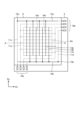
- FIG. 12 is a conceptual diagram showing an example of a touch detection area in a touch sensor.
- a plurality of detection elements 31 are provided in the detection area FA of the touch sensor 30.
- the plurality of detection elements 31 are arranged in a matrix in the detection area FA of the touch sensor 30 in the X direction and the Y direction perpendicular to the X direction.
- the touch sensor 30 has a detection area FA that overlaps a plurality of detection elements 31 arranged in the X direction and the Y direction.
- FIG. 13 is a diagram showing an example of a control block configuration of the control device according to the first embodiment.
- a control block configuration for executing a setting change process to be described later will be described.
- the control device 200 includes a display panel 20, a touch sensor 30, a detection circuit 211, a conversion processing circuit 212, a storage circuit (first storage circuit) 223, a transmission/reception circuit 225, and a display A control circuit 231 is provided.
- the detection circuit 211 is composed of, for example, a detection IC.
- the detection circuit 211 and the display control circuit 231 may be mounted on the display panel 20 as one display IC, or may be mounted on an FPC connected to the display panel 20.
- the conversion processing circuit 212 and the storage circuit 223 are configured by, for example, a CPU, RAM, EEPROM, ROM, etc. of a smartphone or tablet that constitutes the control device 200.
- the display control circuit 231 may be a display IC mounted on the display panel 20 as described above, or may include a GPU of a smartphone, tablet, etc. that constitutes the control device 200. Also good.
- the transmitting/receiving circuit 225 is configured with a wireless communication module such as a smartphone or a tablet that configures the control device 200, for example.
- the detection circuit 211 is a circuit that detects the presence or absence of a touch on the touch sensor 30 based on the detection signal output from each detection element 31 of the touch sensor 30.
- the conversion processing circuit 212 is a circuit that performs conversion processing between the touch detection position in the detection circuit 211 and various setting values (in the present disclosure, light diffusivity) of the lighting device 1. Further, in the present disclosure, the conversion processing circuit 212 has a function of performing conversion processing between the touch detection position in the detection circuit 211, the touched object (image), and the operation state on various screens. .
- the conversion processing circuit 212 is a component implemented by, for example, a CPU of a smartphone, tablet, or the like that constitutes the control device 200.
- the storage circuit 223 is composed of, for example, a RAM, an EEPROM, a ROM, etc. of a smartphone or tablet that constitutes the control device 200.
- the storage circuit 223 stores setting information including various setting values (in the present disclosure, light diffusivity) of the lighting device 1. Further, the storage circuit 223 temporarily stores, for example, intermediate data in a setting change process to be described later.
- the transmitting and receiving circuit 225 transmits and receives setting information to and from the lighting device 1. Specifically, the transmitting/receiving circuit 225 transmits the Dx direction light diffusivity S1x and the Dy direction light diffusivity S1y, which are obtained in a setting change process described later, to the lighting device 1 as first setting information. The transmitting/receiving circuit 225 also receives the second setting information (Dx direction light diffusivity S2x and Dy direction light diffusivity S2y) transmitted from the lighting device 1.
- the second setting information Dx direction light diffusivity S2x and Dy direction light diffusivity S2y
- the display control circuit 231 executes display control processing to display a setting change screen, which will be described later, on the display panel 20.
- the display control circuit 231 controls the display of the display panel 20 based on various setting information and image position information stored in the storage area of the storage circuit 223.
- FIG. 14 is a diagram showing an example of a control block configuration of the lighting device according to the first embodiment.
- the illumination device 1 according to the first embodiment includes a transmitting/receiving circuit 111, an electrode drive circuit 112, and a memory circuit (second memory circuit) 113 as control blocks for controlling the optical element 100 described above. Equipped with
- the transmitting/receiving circuit 111 transmits and receives various setting information to and from the control device 200. Specifically, the transmitting/receiving circuit 111 receives the first setting information (Dx direction light diffusivity S1x and Dy direction light diffusivity S1y) transmitted from the control device 200. Further, the transmitting/receiving circuit 111 transmits the Dx direction light diffusivity S2x and the Dy direction light diffusivity S2y stored in the storage circuit 113 to the control device 200 as second setting information.
- the first setting information Dx direction light diffusivity S1x and Dy direction light diffusivity S1y
- the transmitting/receiving circuit 111 transmits the Dx direction light diffusivity S2x and the Dy direction light diffusivity S2y stored in the storage circuit 113 to the control device 200 as second setting information, which will be described later.
- the Dx direction light diffusivity S1x and the Dy direction light diffusivity S1y of the first setting information transmitted from the control device 200 by the setting change process of the control device 200 are changed to the new Dx direction light diffusivity S2x and Dy direction light diffusivity. It is stored in the memory circuit 113 as S2y. That is, by transmitting the first setting information from the control device 200 to the lighting device 1, the second setting information is updated to the first setting information. Note that the lighting device 1 does not store the second setting information for the first time (both vertical diffusion and horizontal diffusion are 0 [%]). In this case, the second setting information is stored by transmitting the first setting information from the control device 200.
- the electrode drive circuit 112 supplies drive voltages corresponding to the Dx direction light diffusivity S2x and the Dy direction light diffusivity S2y stored in the memory circuit 113 to each drive electrode 10, 13 of each liquid crystal cell 2 of the optical element 100. .
- the electrode drive circuit 112 applies a drive voltage to each drive electrode 10 , 13 of each liquid crystal cell 2 of the optical element 100 in accordance with the second setting information stored in the memory circuit 113 when the lighting device 1 is started. supply to.
- the electrode drive circuit 112 applies a drive voltage to each drive electrode 10 , 13 of each liquid crystal cell 2 of the optical element 100 in accordance with second setting information updated based on the first setting information transmitted from the control device 200 . supply to.
- the storage circuit 113 is composed of, for example, RAM, EEPROM, ROM, etc.
- the memory circuit 113 stores the final value of the second setting information when the lighting device 1 was previously operated.
- FIGS. 15A, FIG. 15B, FIG. 15C, FIG. 15D, and FIG. 15E are conceptual diagrams showing an example of a display mode of a setting change screen of the control device according to the first embodiment.
- the X direction is defined corresponding to the Dx direction (first direction) in light diffusivity control of the lighting device 1
- the Y direction is defined corresponding to the Dy direction (second direction) in light diffusivity control of the lighting device 1.
- an XY plane is defined with the origin O(0,0) being a predetermined position on the display area DA.
- the display panel 20 is provided with a display area DA that overlaps the detection area FA of the touch sensor 30 in plan view.
- a light distribution shape object OBJ whose center point is the origin O(0,0) of the XY plane on the setting change screen 400 is displayed.
- a first slider S1 and a second slider S2 for setting the degree of light diffusion of the illumination device 1 are arranged on the outline of the light distribution shape object OBJ.
- the light distribution shape object OBJ is an image corresponding to the light distribution state of light emitted from the lighting device 1 on the setting change screen 400.
- the first slider S1 and the second slider S2 are, for example, images displayed on the setting change screen 400, and the user can touch and move them (drag operation) with a finger.
- the shape of the light distribution shape object OBJ can be changed.
- the light diffusivity (lateral diffusivity) of the lighting device 1 in the Dx direction is controlled.
- the second slider S2 in the Y direction the shape of the light distribution shape object OBJ can be changed.
- the light diffusivity in the Dy direction (vertical diffusivity) of the lighting device 1 is controlled.
- a selection switch SSEL for a single unit operation mode (first mode) and a selection switch MSEL for a multiple unit operation mode (second mode) are provided on the setting change screen 400. Further, on the setting change screen 400, there are provided a plurality of device selection switches DSEL respectively corresponding to the lighting devices 1_1, 1_2, 1_3, 1_4, and 1_5 registered in advance as controlled devices.
- Each device selection switch DSEL is an image image as a button displayed on the setting display screen, and by selecting one or more of these device selection switches DSEL, the operation target in the device setting process described later.
- a lighting device 1 is selected. Note that each time a new lighting device 1 is registered, the device selection switch DSEL is individually provided corresponding to the lighting device 1, and when the registered lighting device 1 is deleted, the device selection switch DSEL is set to the device corresponding to the lighting device 1.
- the selection switch DSEL is deleted from the setting display screen.
- the illumination device 1 that is to be operated by selecting each device selection switch DSEL will also be referred to as a "device to be operated.”
- selecting a switch means that the user touches the image corresponding to the switch on the setting change screen 400, and the display of the image changes (the shape and color of the image changes). , brightness, etc.). Further, “deselecting the switch” indicates that the user touches the image again and the image returns to its original state.
- the selection switch SSEL is an image of a button displayed on the setting change screen 400. By selecting the selection switch SSEL and selecting one of the images corresponding to the lighting device 1 to be operated from the device selection switch DSEL, the lighting device 1 can be controlled. Details will be described later.
- the selection switch MSEL is an image of a button displayed on the setting change screen 400. By selecting the selection switch SSEL and selecting one or more of the images corresponding to the lighting device 1 to be operated from the device selection switch DSEL, the selected lighting device can be controlled. Details will be described later.
- the positions where the device selection switch DSEL, selection switch SSEL, and selection switch MSEL are provided are not limited to the embodiments shown in FIGS. 15A, 15B, 15C, 15D, and 15E.
- the single operation mode and the multiple unit operation mode are operation modes that are exclusively selected.
- the mode switches to the multiple unit operation mode. Further, for example, when the selection switch SSEL is touched in the multiple device operation mode, the mode is switched to the single device operation mode.
- the behavior when the device selection switch DSEL is operated is different between the single unit operation mode and the multiple unit operation mode.
- the target device to be operated singly changes from the lighting device 1_1 to the lighting device Switch to 1_2. That is, in the single operation mode, any one of the plurality of lighting devices 1_1, 1_2, 1_3, 1_4, and 1_5 registered in advance as a device to be controlled is selected as a device to be operated, and can be operated independently.
- the multiple unit operation mode for example, when lighting device 1_1 is selected, if the device selection switch DSEL corresponding to lighting device 1_2 is selected, the two devices to be operated become lighting device 1_1 and lighting device 1_2. . Thereafter, when the selection of the device selection switch DSEL corresponding to the lighting device 1_2 is deselected again, the lighting device 1_2 is excluded from the devices to be operated, and the only device to be operated is the lighting device 1_1. Alternatively, when there are two devices to be operated, lighting device 1_1 and lighting device 1_2, if the device selection switch DSEL corresponding to lighting device 1_1 is deselected, lighting device 1_1 is excluded from the devices to be operated, and There is only one device, lighting device 1_2.
- the operation target device when at least one of the plurality of lighting devices 1_1, 1_2, 1_3, 1_4, and 1_5 registered in advance as a control target device is selected as an operation target device, the operation target device is When a plurality of control target devices (for example, the selected lighting device 1_1 and lighting device 1_2) are selected as operation target devices, the selected operation target devices (for example, the lighting device 1_1 and the lighting device 1_2) can be operated independently. The lighting devices 1_2) can be operated simultaneously.
- the device selection switch DSEL when transmitting the same setting information (light diffusivity information in this disclosure) for multiple lighting devices, select the device selection switch DSEL to switch the operation target device, and select the device selection switch DSEL to switch the operation target device (for example, It is necessary to make the same setting changes for each of the lighting device 1_1 and the lighting device 1_2).
- the same setting change is applied to a plurality of selected operation target devices (for example, lighting device 1_1 and lighting device 1_2).
- a plurality of selected operation target devices for example, lighting device 1_1 and lighting device 1_2.
- the number of devices to be controlled by the control device 200 is not limited to five.
- the number of devices (lighting devices 1) to be controlled by the control device 200 may be N (N is a natural number of 1 or more).
- the operation target device (lighting device 1) selected in the multiple device operation mode (second mode) The number may be explained as M (M is a natural number from 1 to N).
- FIG. 15A shows a setting change screen 400 when the lighting device 1_1 is selected as the device to be operated in the single operation mode.
- FIG. 15A shows an example in which the Dx direction light diffusivity Sx of the lighting device 1_1 is 50% and the Dy direction light diffusivity Sy is 50%.
- the numerical values of the Dx direction light diffusivity Sx and the Dy direction light diffusivity Sy are also displayed on the display screen. Note that, hereinafter, the Dx direction light diffusivity Sx will be referred to as the lateral diffusivity Sx, and the Dy direction light diffusivity Sy will be referred to as the vertical diffusivity Sy.
- FIG. 15B shows the setting change screen 400 when the lighting device 1_2 is selected as the device to be operated in the single operation mode.
- FIG. 15B shows an example in which both the horizontal diffusivity Sx and the vertical diffusivity Sy of the lighting device 1_2 are 100%.
- FIG. 15C shows the setting change screen 400 when the lighting device 1_3 is selected as the device to be operated in the single operation mode.
- FIG. 15C shows an example in which both the horizontal diffusivity Sx and the vertical diffusivity Sy of the lighting device 1_3 are 0%.
- FIG. 15D shows the setting change screen 400 when the lighting device 1_4 is selected as the device to be operated in the single operation mode.
- FIG. 15D shows an example in which the lateral diffusivity Sx of the lighting device 1_4 is 100 [%] and the vertical diffusivity Sy is 50 [%].
- FIG. 15E shows a setting change screen 400 when lighting devices 1_1, 1_2, and 1_3 are selected as devices to be operated in the multiple device operation mode.
- FIG. 15E shows an example in which the horizontal diffusivity Sx and vertical diffusivity Sy of the lighting devices 1_1, 1_2, and 1_3 are set to initial values (default values) in a setting change process described later.
- FIG. 15E an example is shown in which both the initial value of the horizontal diffusivity Sx and the initial value of the vertical diffusivity Sy are 50[%], but the initial value of the horizontal diffusivity Sx and the initial value of the vertical diffusivity Sy are is not limited to 50[%], and can be set to any value such as 0%, 30%, 100%, etc. Further, the initial value of the horizontal diffusivity Sx and the initial value of the vertical diffusivity Sy may be different from each other. Note that the setting change procedure in the multiple device operation mode will be explained in detail in the setting change process described later.
- the shape of the light distribution shape object OBJ on the setting change screen 400 can be moved to the first slider S1 and the second slider S2, as shown in FIGS. 15A, 15B, 15C, 15D, and 15E. As a result, it changes into a circular or oval shape.
- a first area TA1 is provided as an area in which the first slider S1 can be operated.
- the first slider S1 is set within the first area TA1 from the position on the outline of the light distribution shape object OBJ when the lateral diffusivity Sx is 0[%] to when the lateral diffusivity Sx is 100[%]. Movement in the X direction is possible up to a position on the outline of the light distribution shape object OBJ. Therefore, the first slider S1 does not move if the user's finger leaves the screen, or if it leaves the first area TA1 without leaving the screen.
- a second area TA2 is provided as an area in which the second slider S2 can be operated.
- the second slider S2 is set in the second area TA2 when the vertical diffusivity Sy is 100[%] from the position on the outline of the light distribution shape object OBJ when the vertical diffusivity Sy is 0[%]. Movement in the Y direction is possible up to a position on the outline of the light distribution shape object OBJ. Therefore, the second slider S2 does not move if the user's finger leaves the screen, or if the user's finger leaves the second area TA2 without leaving the screen.
- FIG. 16 is a diagram illustrating the relationship between the position on the setting change screen of the control device and the degree of light diffusion according to the first embodiment.
- the position (coordinates) of the display panel 20 on the display area DA and the position (coordinates) of the touch sensor 30 on the detection area FA will be described as being equivalent.
- the lateral diffusivity Sx of the lighting device 1 is determined by the amount of movement of the position x of the intersection of the X axis of the XY plane and the outline of the light distribution shape object OBJ. Can be set.
- the position x of the intersection of the X-axis and the outline of the light distribution shape object OBJ is set as the center point of the first slider S1.
- the position x0 of the first slider S1 on the display area DA overlaps with the position x of the intersection of the X-axis and the outline of the light distribution shape object OBJ.
- the lateral diffusivity Sx of the lighting device 1 can be set by touching the first slider S1 and moving it in the X-axis direction.
- “Sx” in FIG. 16 indicates the lateral diffusivity (for example, “50” [%]) of the lighting device 1.
- the reference movement amount Px in the X direction on the XY plane when the lateral diffusivity variation ⁇ Sx of the lighting device 1 is 1 [%] is the light distribution when the X axis and the lateral diffusivity Sx are 100 [%] If the intersection with the outline of the shape object OBJ is X 100 , and the intersection between the X axis and the outline of the light distribution shape object OBJ when the lateral diffusivity Sx is 0 [%] is X 0 , then the following (1) is obtained. It is shown by the formula.
- the vertical diffusivity Sy of the lighting device 1 is determined by the movement of the position y of the intersection of the Y axis of the XY plane and the outline of the light distribution shape object OBJ. It can be set depending on the amount.
- the position y of the intersection of the Y-axis and the outline of the light distribution shape object OBJ is set as the center point of the second slider S2.
- the position y0 of the second slider S2 on the display area DA overlaps with the position y of the intersection of the Y-axis and the outline of the light distribution shape object OBJ.
- the vertical diffusivity Sy of the lighting device 1 can be set.
- “Sy” in FIG. 16 indicates the vertical diffusion degree (for example, “50” [%]) of the lighting device 1.
- the reference movement amount Py in the Y direction on the XY plane when the lateral diffusivity change ⁇ Sy of the lighting device 1 is 1% is the light distribution when the Y axis and the vertical diffusivity Sy are 100%. If the intersection with the outline of the shape object OBJ is Y 100 and the intersection between the Y axis and the outline of the light distribution shape object OBJ when the vertical diffusivity Sy is 0 [%] is Y 0 , then the following (4) is obtained. It is shown by the formula.
- the circular light distribution shape object OBJ is displayed when both the horizontal diffusivity Sx and the vertical diffusivity Sy are set to 0%, but the present invention is not limited to this.
- the origin O(0,0) of the XY plane on the setting change screen 400 may be the position when both the horizontal diffusivity Sx and the vertical diffusivity Sy are set to 0%. .
- FIG. 17 is a flowchart illustrating an example of a setting change process in the control device of the lighting device according to the first embodiment.
- FIG. 18 is a conceptual diagram showing an example of a storage area in the control device for the lighting device according to the first embodiment.
- the setting change process shown in FIG. 17 is realized, for example, by application software executed on a CPU of a smartphone, tablet, etc. that constitutes the control device 200.
- application software for realizing the setting change process of the lighting device 1_n will also be simply referred to as a "setting change application.”
- the settings change application can display a device registration screen for registering a device to be controlled on the display area DA.
- the device registration screen may be a sub-screen that is explicitly transitioned to when registering a controlled device after starting the settings change app, or it may be an initial screen that is displayed immediately after starting the settings change app. good.
- a mode will be described in which, when the settings change application is started, the single operation mode is selected as the default setting of the operation mode, and the lighting device 1_1 is selected as the device to be operated in the single operation mode.
- the transmitting/receiving circuit 111 of the lighting device 1_1 reads out the second setting information stored in the storage circuit 113 and transmits it to the control device 200. Further, the electrode drive circuit 112 of the lighting device 1_1 supplies a drive voltage according to the second setting information to each drive electrode 10, 13 of each liquid crystal cell 2 of the optical element 100.
- the transmitting/receiving circuit 225 of the control device 200 determines whether or not the second setting information has been received from the lighting device 1_1 (step S003). If the second setting information has not been received from the lighting device 1_1 (step S003; No), the process of step S003 is repeatedly executed.
- the transmitting/receiving circuit 225 sets the Dx direction light diffusivity S2x_1 of the second setting information of the lighting device 1_1 to the lateral diffusivity Sx_1, and sets the Dy direction light
- the degree of diffusion S2y_1 is stored as the degree of vertical diffusion Sy_1 in the storage area of the storage circuit 223 shown in FIG. 18 (step S004).
- the storage circuit 223 of the control device 200 stores the current horizontal diffusivity Sx_n and vertical diffusivity Sy_n of each lighting device 1_n.
- the horizontal diffusivity Sx_4 and the vertical diffusivity Sy_4 in the lighting device 1_5 are set to "**".
- the lateral diffusivity Sx_n and the vertical diffusivity Sy_n of each lighting device 1_n are merely examples, and are not limited to the example shown in FIG. 18.
- the transmitting/receiving circuit 111 of the lighting device 1_n reads out the second setting information stored in the storage circuit 113 and transmits it to the control device 200. Further, the electrode drive circuit 112 of the lighting device 1_n supplies a drive voltage according to the second setting information stored in the memory circuit 113 to each drive electrode 10, 13 of each liquid crystal cell 2 of the optical element 100.
- the transmitting/receiving circuit 225 of the control device 200 determines whether or not the second setting information has been received from the lighting device 1_n (step S003). If the second setting information has not been received from the lighting device 1_n (step S003; No), the process of step S003 is repeatedly executed.
- the transmitting/receiving circuit 225 sets the Dx direction light diffusivity S2x_n of the second setting information of the lighting device 1_n to the lateral diffusivity Sx_n, and sets the Dy direction light
- the degree of diffusion S2y_n is stored as the degree of vertical diffusion Sy_n in the storage area of the storage circuit 223 shown in FIG. 18 (step S004).
- the horizontal diffusivity Sx_n and vertical diffusivity Sy_n of all controlled devices are acquired and stored in the storage area of the storage circuit 223 (see FIG. 18).
- control device 200 determines whether the multiple unit operation mode is selected (step S006).
- the single operation mode is selected as the default setting (initial setting) of the operation mode, as described above. That is, in step S006 immediately after starting the settings change application, the single operation mode is selected (step S006; No).
- the display control circuit 231 of the control device 200 displays the horizontal diffusion degree Sx_1 and the vertical diffusion degree of the lighting device 1_1 stored in the storage area of the storage circuit 223.
- the degree Sy_1 is read out (step S007), and display control of the display panel 20 is executed (step S008).
- the current values in FIG. 18 indicate the current horizontal diffusivity Sx and vertical diffusivity Sy displayed on the setting change screen 400.
- the horizontal diffusivity Sx_1 and vertical diffusivity Sy_1 of 1_1 are overwritten as the current horizontal diffusivity Sx and vertical diffusivity Sy.
- the setting change screen 400 on which the horizontal diffusion degree Sx_1 and the vertical diffusion degree Sy_1 of the lighting device 1_1 are reflected is displayed on the display area DA as the default screen in the single operation mode immediately after the setting change application is started.
- control device 200 determines whether the device to be operated has been changed (step S011).
- step S011; No the display control circuit 231 of the control device 200 selects the lighting device 1_s (which is set by default as the device to be operated) in the single operation mode immediately after starting the setting change application.
- step S101 it is determined whether a setting change of the setting information (in the present disclosure, light diffusivity information) of the lighting device 1_1) has been performed (step S101). If the settings of the setting information have not been changed (step S101; No), the control device 200 returns to the process of step S006.
- the conversion processing circuit 212 executes, for example, touch detection processing for the first slider S1 and touch detection processing for the second slider S2 on the setting change screen 400.
- the conversion processing circuit 212 calculates the current lateral diffusivity Sx based on the X-direction position on the detection area FA of the first slider S1, and stores it in the storage area of the storage circuit 223. do. More specifically, by operating the first slider S1, the current value of the lateral diffusivity Sx shown in FIG. 18 is updated and overwritten.
- the conversion processing circuit 212 calculates the current vertical diffusivity Sy based on the Y-direction position of the second slider S2 on the detection area FA, and stores it in the storage area of the storage circuit 223. do. More specifically, by operating the second slider S2, the current value of the vertical diffusivity Sy shown in FIG. 18 is updated and overwritten.
- step S101 When the settings of the settings information are changed on the settings change screen 400 (step S101; Yes), the display control circuit 231 of the control device 200 changes the settings on the settings change screen 400 and changes the current information on the display that has been overwritten.
- the values lateral diffusivity Sx and vertical diffusivity Sy are read out (step S102), and display control of the display panel 20 is executed (step S103).
- the transmitting/receiving circuit 225 of the control device 200 transmits the first setting information to the lighting device 1_s (in this disclosure, the lighting device 1_1) which is set by default as the operation target device when the settings change application is started.
- the first setting information is transmitted to the lighting device 1_s (1_1) which is set by default as the operation target device when the setting change application is started (step S108).
- the transmitting/receiving circuit 111 of the lighting device 1_s (1_1) stores the received first setting information in the storage circuit 113 as second setting information.
- the electrode drive circuit 112 of the lighting device 1_n (1_1) supplies a drive voltage according to the second setting information stored in the memory circuit 113 to each drive electrode 10, 13 of each liquid crystal cell 2 of the optical element 100. Then, the transmitting/receiving circuit 111 of the lighting device 1_s (1_1) reads out the second setting information stored in the storage circuit 113 and transmits it to the control device 200.
- the transmitting/receiving circuit 225 of the control device 200 determines whether or not the second setting information has been received from the lighting device 1_s (1_1) (step S110). If the second setting information is not received from the lighting device 1_s (1_1) (step S110; No), the process of step S110 is repeatedly executed.
- the transmitting/receiving circuit 225 converts the Dx direction light diffusivity S2x_s (S2x_1) of the second setting information of the lighting device 1_s into the lateral diffusivity.
- Sx_s (Sx_1), Dy direction light diffusivity S2y_s (S2y_1) is stored as longitudinal diffusivity Sy_s (Sy_1) in the storage area of the storage circuit 223 (step S111).
- the transmitting/receiving circuit 111 of the lighting device 1_s stores the received first setting information in the storage circuit 113 as second setting information.
- the electrode drive circuit 112 of the lighting device 1_n supplies a drive voltage according to the second setting information stored in the memory circuit 113 to each drive electrode 10, 13 of each liquid crystal cell 2 of the optical element 100. Then, the transmitting/receiving circuit 111 of the lighting device 1_s reads out the second setting information stored in the storage circuit 113 and transmits it to the control device 200.
- the transmitting/receiving circuit 225 of the control device 200 determines whether or not the second setting information has been received from the lighting device 1_s (step S110). If the second setting information has not been received from the lighting device 1_s (step S110; No), the process of step S110 is repeatedly executed.
- the transmitting/receiving circuit 225 sets the Dx direction light diffusivity S2x_s of the second setting information of the lighting device 1_s to the lateral diffusivity Sx_s, and sets the Dy direction light
- the degree of diffusion S2y_s is stored as the degree of vertical diffusion Sy_s in the storage area of the storage circuit 223 (step S111). Thereby, the settings of the lighting device 1_s selected as the device to be operated in the single operation mode are changed.
- step S101 When the settings of the settings information are changed on the settings change screen 400 (step S101; Yes), the display control circuit 231 of the control device 200 changes the settings on the settings change screen 400 and changes the current information on the display that has been overwritten.
- the values lateral diffusivity Sx and vertical diffusivity Sy are read out (step S102), and display control of the display panel 20 is executed (step S103).
- the transmitting/receiving circuit 111 of the lighting device 1_s stores the received first setting information in the storage circuit 113 as second setting information.
- the electrode drive circuit 112 of the lighting device 1_n supplies a drive voltage according to the second setting information stored in the memory circuit 113 to each drive electrode 10, 13 of each liquid crystal cell 2 of the optical element 100. Then, the transmitting/receiving circuit 111 of the lighting device 1_s reads out the second setting information stored in the storage circuit 113 and transmits it to the control device 200.
- the transmitting/receiving circuit 225 of the control device 200 determines whether or not the second setting information has been received from the lighting device 1_s (step S110). If the second setting information has not been received from the lighting device 1_s (step S110; No), the process of step S110 is repeatedly executed.
- the transmitting/receiving circuit 225 sets the Dx direction light diffusivity S2x_s of the second setting information of the lighting device 1_s to the lateral diffusivity Sx_s, and sets the Dy direction light
- the degree of diffusion S2y_s is stored as the degree of vertical diffusion Sy_s in the storage area of the storage circuit 223 (step S111). As a result, the settings of the only lighting device 1_s selected as the device to be operated in the multiple device operation mode are changed.
- the control device 200 selects the devices to be operated in the multiple unit operation mode. It is determined whether the light distribution shapes of the M lighting devices 1_m (1_a, 1_b, . . . ) are the same. Specifically, the control device 200 controls the M lighting devices 1_m (1_a, 1_b, . . . ) to have the same lateral diffusivity Sx_m (Sx_a, Sx_b, . . . ), and It is determined whether the vertical diffusivity Sy_m (Sy_a, Sy_b, . . .) of 1_m (1_a, 1_b, . . . ) is the same (step S013).
- step S201 If the light distribution shapes of the M lighting devices 1_m (1_a, 1_b, . . . ) selected as operation target devices in the multiple device operation mode are the same (step S013; Yes), the process moves to step S201.
- the display control circuit 231 of the control device 200 reads out the lateral diffusivity Sx_ini (50 [%] in FIG. 18), which is the initial value (default value) of the lateral diffusivity Sx stored in the storage area of the storage circuit 223, and sets it as the current value of the lateral diffusivity Sx; Furthermore, the vertical diffusivity Sy_ini (50 [%] in the example shown in FIG.
- step S009 executes display control of the display panel 20 (step S010), and moves to step S201.
- the display control circuit 231 of the control device 200 determines whether or not the settings of the plurality of lighting devices 1_m selected as devices to be operated in the multiple device operation mode have been changed (step S201). If the settings of the setting information have not been changed (step S201; No), the control device 200 returns to the process of step S006.
- step S201 When the settings of the settings information are changed on the settings change screen 400 (step S201; Yes), the display control circuit 231 of the control device 200 changes the settings on the settings change screen 400 and displays the current information on the display that has been overwritten.
- the values lateral diffusivity Sx and vertical diffusivity Sy are read out (step S202), and display control of the display panel 20 is executed (step S203).
- the transmitting/receiving circuit 111 of the lighting device 1_m stores the received first setting information in the storage circuit 113 as second setting information.
- the electrode drive circuit 112 of the lighting device 1_m supplies a drive voltage according to the second setting information stored in the memory circuit 113 to each drive electrode 10, 13 of each liquid crystal cell 2 of the optical element 100. Then, the transmitting/receiving circuit 111 of the lighting device 1_m reads out the second setting information stored in the storage circuit 113 and transmits it to the control device 200.
- the transmitting/receiving circuit 225 of the control device 200 determines whether or not the second setting information has been received from the lighting device 1_m (step S210). If the second setting information has not been received from the lighting device 1_m (step S210; No), the process of step S210 is repeatedly executed.
- the transmitting/receiving circuit 225 Upon receiving the second setting information from the lighting device 1_m (step S210; Yes), the transmitting/receiving circuit 225 sets the Dx direction light diffusivity S2x_m of the second setting information of the lighting device 1_m to the lateral diffusivity Sx_m, and sets the Dy direction light
- the degree of diffusion S2y_m is stored as the degree of vertical diffusion Sy_m in the storage area of the storage circuit 223 (step S211).
- step S206 to step S211 The above processing from step S206 to step S211 is executed for M lighting devices 1_m selected as operation target devices in the multiple device operation mode. As a result, the same setting change is performed for the M lighting devices 1_m selected as devices to be operated in the multiple device operation mode.
- the plurality of lighting devices selected at the time of selecting the multiple unit operation mode from among the plurality of lighting devices 1_n registered in advance as control target devices. 1_m the same setting information (in this disclosure, light diffusivity information) can be set all at once.
- the setting change screen 400 is displayed for each of the plurality of lighting devices 1_n (see FIG. 15A, FIG. 15B, FIG. 15C, FIG. 15D, and FIG. 15E).
- the present invention is not limited to the manner in which the setting change screen 400 is displayed for each device 1_n.
- the display area DA of the control device 200 is a tablet or the like that is sufficiently wide, the settings of a plurality of lighting devices 1_n registered as devices to be controlled may be changed on one screen.
- FIG. 19A is a schematic diagram illustrating an example of the configuration of a lighting system according to Embodiment 2.
- the lighting control device 200a includes a DMX controller and the like.
- the DMX controller can not only adjust the brightness and color of the light emitted from the lighting devices 1_1, 1_2, ..., 1_N, but also adjust the brightness and color of the light emitted from the lighting devices 1_1, 1_2, ..., 1_N.
- the element 100 can be operated, thereby making it possible to change the light distribution shape of the emitted light from each lighting device 1_1, 1_2, . . . , 1_N.
- FIG. 19B is a schematic diagram showing a specific connection example when the lighting control device is a DMX controller in the configuration of the lighting system according to the second embodiment.
- the lighting control device 200a is a DMX controller
- the lighting control device 200a and the plurality of lighting devices 1_1, 1_2, ..., 1_N are connected in a daisy chain, as shown in FIG. 19B. More specifically, the lighting control device 200a and the lighting device 1_1 are connected by a cable 310_1, and the lighting device 1_1 and the lighting device 1_2 are connected by a cable 310_2. Thereafter, the front-stage lighting device and the rear-stage lighting device are sequentially connected by cable.
- the lighting system includes a plurality of lighting devices 1_1, 1_2, ..., 1_N and one lighting control device 200a, which are connected by wire. More specifically, each lighting device 1_1, 1_2, ..., 1_N includes a light source 4 and an optical element 100 as in the first embodiment, and the lighting control device 200a includes a plurality of physical sliders 200b. There is. Further, the light source 4 and optical element 100 of each lighting device 1_1, 1_2, ..., 1_N are connected to the lighting control device 200a via wiring 310 (or cable 310_1, 310_2, ..., 310_N), Accordingly, each light source 4 or each optical element 100 can be driven by moving the physical slider (hereinafter referred to as a slider) 200b up and down.
- a slider physical slider
- each light source 4 and the slider 200b have a one-to-one correspondence, and by moving the slider 200b up and down, the brightness of the light emitted from the light source 4 can be changed.
- the color of the light emitted from the light source 4 is changed by moving the slider 200b up and down, and it is also possible to change both the brightness and color.
- two sliders 200b may be associated with each light source 4, and the brightness of the light emitted from the light source 4 can be changed by moving one slider 200b up and down, and the brightness of the light emitted from the light source 4 can be changed by moving the other slider 200b up and down. It is also possible to adopt a configuration in which the color of the emitted light from 4 is changed.
- two wires 310 are drawn out from the optical element 100 of each lighting device 1_1, 1_2, . . . , 1_N and connected to the lighting control device 200a.
- two sliders 200b correspond to each optical element 100, and by moving one slider 200b up and down, the lateral diffusivity of the optical element 100 can be changed, and by moving the other slider 200b up and down.
- the longitudinal diffusivity of the optical element 100 can be changed by. It goes without saying that by simultaneously moving the plurality of sliders 200b up and down, the vertical and horizontal diffusivity of the plurality of optical elements 100 can be changed simultaneously.
- slider 200b corresponding to a plurality of optical elements 100 selectively selected from the plurality of optical elements 100 is provided, and by moving the slider 200b up and down, the selected plurality of optical elements 100 can be adjusted.
- a configuration in which the degree of diffusion is changed can also be adopted.
- the operation of operating the slider 200b of the illumination control device 200a to change the degree of diffusion of one optical element 100 may be referred to as a single operation mode (first mode) in correspondence with the first embodiment.
- a mode in which one or more sliders 200b of the illumination control device 200a are operated to simultaneously change the degree of diffusion of a plurality of optical elements 100 is referred to as a multiple unit operation mode (second mode) in correspondence with the first embodiment. It's fine.
- the lighting control device 200a can be connected to an external control device 500 such as a PC via a port 200c, and the external control device 500 can control the settings of the lighting control device 200a, more specifically, each slider 200b.
- the degree of diffusion and change in brightness of the light emitted from each illumination device 1_1, 1_2, ..., 1_N due to the combination of correspondence among the illumination devices 1_1, 1_2, ..., 1_N and the vertical movement of each slider 200b can be changed.
- each lighting device 1_1, 1_2, ..., 1_N and the lighting control device 200a having the slider 200b are connected by wireless communication means. can also be adopted.
Landscapes
- Physics & Mathematics (AREA)
- Engineering & Computer Science (AREA)
- General Engineering & Computer Science (AREA)
- Chemical & Material Sciences (AREA)
- Crystallography & Structural Chemistry (AREA)
- Nonlinear Science (AREA)
- General Physics & Mathematics (AREA)
- Mathematical Physics (AREA)
- Optics & Photonics (AREA)
- Computer Networks & Wireless Communication (AREA)
- Human Computer Interaction (AREA)
- Computer Hardware Design (AREA)
- Theoretical Computer Science (AREA)
- Liquid Crystal (AREA)
- Circuit Arrangement For Electric Light Sources In General (AREA)
Priority Applications (6)
| Application Number | Priority Date | Filing Date | Title |
|---|---|---|---|
| EP23856954.5A EP4580316A1 (en) | 2022-08-25 | 2023-06-23 | Illumination system and control device |
| JP2024542606A JP7746591B2 (ja) | 2022-08-25 | 2023-06-23 | 照明システム及び制御装置 |
| CN202380061836.XA CN119769177A (zh) | 2022-08-25 | 2023-06-23 | 照明系统以及控制装置 |
| KR1020257005420A KR102932127B1 (ko) | 2022-08-25 | 2023-06-23 | 조명 시스템 및 제어 장치 |
| US19/055,259 US20250189101A1 (en) | 2022-08-25 | 2025-02-17 | Illumination system and control device |
| MX2025002181A MX2025002181A (es) | 2022-08-25 | 2025-02-21 | Sistema de iluminacion y dispositivo de control |
Applications Claiming Priority (2)
| Application Number | Priority Date | Filing Date | Title |
|---|---|---|---|
| JP2022134383 | 2022-08-25 | ||
| JP2022-134383 | 2022-08-25 |
Related Child Applications (1)
| Application Number | Title | Priority Date | Filing Date |
|---|---|---|---|
| US19/055,259 Continuation US20250189101A1 (en) | 2022-08-25 | 2025-02-17 | Illumination system and control device |
Publications (1)
| Publication Number | Publication Date |
|---|---|
| WO2024042837A1 true WO2024042837A1 (ja) | 2024-02-29 |
Family
ID=90012852
Family Applications (1)
| Application Number | Title | Priority Date | Filing Date |
|---|---|---|---|
| PCT/JP2023/023330 Ceased WO2024042837A1 (ja) | 2022-08-25 | 2023-06-23 | 照明システム及び制御装置 |
Country Status (7)
| Country | Link |
|---|---|
| US (1) | US20250189101A1 (https=) |
| EP (1) | EP4580316A1 (https=) |
| JP (1) | JP7746591B2 (https=) |
| KR (1) | KR102932127B1 (https=) |
| CN (1) | CN119769177A (https=) |
| MX (1) | MX2025002181A (https=) |
| WO (1) | WO2024042837A1 (https=) |
Families Citing this family (1)
| Publication number | Priority date | Publication date | Assignee | Title |
|---|---|---|---|---|
| WO2024048166A1 (ja) * | 2022-09-01 | 2024-03-07 | 株式会社ジャパンディスプレイ | 照明装置 |
Citations (4)
| Publication number | Priority date | Publication date | Assignee | Title |
|---|---|---|---|---|
| JPH0265001A (ja) | 1988-08-30 | 1990-03-05 | Sekisui Chem Co Ltd | 照明器具の調光装置 |
| JP2014093147A (ja) * | 2012-11-01 | 2014-05-19 | Japan Science & Technology Agency | 照明システムおよび照明制御方法 |
| WO2018055722A1 (ja) * | 2016-09-23 | 2018-03-29 | マクセル株式会社 | 映像投射照明装置 |
| WO2021166807A1 (ja) * | 2020-02-21 | 2021-08-26 | ソニーグループ株式会社 | 光源装置、及び画像表示装置 |
-
2023
- 2023-06-23 KR KR1020257005420A patent/KR102932127B1/ko active Active
- 2023-06-23 JP JP2024542606A patent/JP7746591B2/ja active Active
- 2023-06-23 WO PCT/JP2023/023330 patent/WO2024042837A1/ja not_active Ceased
- 2023-06-23 CN CN202380061836.XA patent/CN119769177A/zh active Pending
- 2023-06-23 EP EP23856954.5A patent/EP4580316A1/en active Pending
-
2025
- 2025-02-17 US US19/055,259 patent/US20250189101A1/en active Pending
- 2025-02-21 MX MX2025002181A patent/MX2025002181A/es unknown
Patent Citations (4)
| Publication number | Priority date | Publication date | Assignee | Title |
|---|---|---|---|---|
| JPH0265001A (ja) | 1988-08-30 | 1990-03-05 | Sekisui Chem Co Ltd | 照明器具の調光装置 |
| JP2014093147A (ja) * | 2012-11-01 | 2014-05-19 | Japan Science & Technology Agency | 照明システムおよび照明制御方法 |
| WO2018055722A1 (ja) * | 2016-09-23 | 2018-03-29 | マクセル株式会社 | 映像投射照明装置 |
| WO2021166807A1 (ja) * | 2020-02-21 | 2021-08-26 | ソニーグループ株式会社 | 光源装置、及び画像表示装置 |
Also Published As
| Publication number | Publication date |
|---|---|
| CN119769177A (zh) | 2025-04-04 |
| MX2025002181A (es) | 2025-05-02 |
| KR102932127B1 (ko) | 2026-02-27 |
| JP7746591B2 (ja) | 2025-09-30 |
| US20250189101A1 (en) | 2025-06-12 |
| JPWO2024042837A1 (https=) | 2024-02-29 |
| EP4580316A1 (en) | 2025-07-02 |
| KR20250040695A (ko) | 2025-03-24 |
Similar Documents
| Publication | Publication Date | Title |
|---|---|---|
| WO2023145347A1 (ja) | 照明装置及び照明制御システム | |
| US20250189101A1 (en) | Illumination system and control device | |
| JP7570541B2 (ja) | 照明装置 | |
| HK40118948A (zh) | 照明系统以及控制装置 | |
| JP7615362B2 (ja) | 照明システムの制御装置 | |
| US20250311078A1 (en) | Control device for illumination device, and illumination system | |
| US20260002661A1 (en) | Control device for illumination device | |
| JP7708975B2 (ja) | 照明装置の制御装置、及び照明システム | |
| WO2024135247A1 (ja) | 照明装置の制御装置 | |
| JP7735595B2 (ja) | 照明装置の制御装置 | |
| JP7542756B2 (ja) | 照明装置の制御装置 | |
| US20260004750A1 (en) | Control device for illumination device | |
| WO2024185300A1 (ja) | 照明システム | |
| JP7592898B2 (ja) | 照明システム | |
| WO2024024433A1 (ja) | 照明装置、及び照明システム | |
| HK40116976A (zh) | 照明装置的控制装置以及照明系统 |
Legal Events
| Date | Code | Title | Description |
|---|---|---|---|
| 121 | Ep: the epo has been informed by wipo that ep was designated in this application |
Ref document number: 23856954 Country of ref document: EP Kind code of ref document: A1 |
|
| WWE | Wipo information: entry into national phase |
Ref document number: 2024542606 Country of ref document: JP |
|
| ENP | Entry into the national phase |
Ref document number: 20257005420 Country of ref document: KR Kind code of ref document: A |
|
| WWE | Wipo information: entry into national phase |
Ref document number: 202517014396 Country of ref document: IN Ref document number: 1020257005420 Country of ref document: KR |
|
| WWE | Wipo information: entry into national phase |
Ref document number: MX/A/2025/002181 Country of ref document: MX |
|
| WWE | Wipo information: entry into national phase |
Ref document number: 202380061836.X Country of ref document: CN |
|
| REG | Reference to national code |
Ref country code: BR Ref legal event code: B01A Ref document number: 112025003441 Country of ref document: BR |
|
| WWP | Wipo information: published in national office |
Ref document number: 202517014396 Country of ref document: IN |
|
| WWP | Wipo information: published in national office |
Ref document number: 1020257005420 Country of ref document: KR |
|
| WWE | Wipo information: entry into national phase |
Ref document number: 2023856954 Country of ref document: EP |
|
| NENP | Non-entry into the national phase |
Ref country code: DE |
|
| ENP | Entry into the national phase |
Ref document number: 2023856954 Country of ref document: EP Effective date: 20250325 |
|
| WWP | Wipo information: published in national office |
Ref document number: 202380061836.X Country of ref document: CN |
|
| WWP | Wipo information: published in national office |
Ref document number: MX/A/2025/002181 Country of ref document: MX |
|
| WWP | Wipo information: published in national office |
Ref document number: 2023856954 Country of ref document: EP |
|
| ENP | Entry into the national phase |
Ref document number: 112025003441 Country of ref document: BR Kind code of ref document: A2 Effective date: 20250221 |
|
| WWG | Wipo information: grant in national office |
Ref document number: 1020257005420 Country of ref document: KR |