WO2024042811A1 - 可変容量形オイルポンプ、及び可変容量形オイルポンプの製造方法 - Google Patents
可変容量形オイルポンプ、及び可変容量形オイルポンプの製造方法 Download PDFInfo
- Publication number
- WO2024042811A1 WO2024042811A1 PCT/JP2023/020913 JP2023020913W WO2024042811A1 WO 2024042811 A1 WO2024042811 A1 WO 2024042811A1 JP 2023020913 W JP2023020913 W JP 2023020913W WO 2024042811 A1 WO2024042811 A1 WO 2024042811A1
- Authority
- WO
- WIPO (PCT)
- Prior art keywords
- coil spring
- variable displacement
- cam ring
- pump
- housing
- Prior art date
- Legal status (The legal status is an assumption and is not a legal conclusion. Google has not performed a legal analysis and makes no representation as to the accuracy of the status listed.)
- Ceased
Links
Images

Classifications
-
- F—MECHANICAL ENGINEERING; LIGHTING; HEATING; WEAPONS; BLASTING
- F04—POSITIVE - DISPLACEMENT MACHINES FOR LIQUIDS; PUMPS FOR LIQUIDS OR ELASTIC FLUIDS
- F04C—ROTARY-PISTON, OR OSCILLATING-PISTON, POSITIVE-DISPLACEMENT MACHINES FOR LIQUIDS; ROTARY-PISTON, OR OSCILLATING-PISTON, POSITIVE-DISPLACEMENT PUMPS
- F04C14/00—Control of, monitoring of, or safety arrangements for, machines, pumps or pumping installations
- F04C14/18—Control of, monitoring of, or safety arrangements for, machines, pumps or pumping installations characterised by varying the volume of the working chamber
- F04C14/22—Control of, monitoring of, or safety arrangements for, machines, pumps or pumping installations characterised by varying the volume of the working chamber by changing the eccentricity between cooperating members
- F04C14/223—Control of, monitoring of, or safety arrangements for, machines, pumps or pumping installations characterised by varying the volume of the working chamber by changing the eccentricity between cooperating members using a movable cam
-
- F—MECHANICAL ENGINEERING; LIGHTING; HEATING; WEAPONS; BLASTING
- F04—POSITIVE - DISPLACEMENT MACHINES FOR LIQUIDS; PUMPS FOR LIQUIDS OR ELASTIC FLUIDS
- F04C—ROTARY-PISTON, OR OSCILLATING-PISTON, POSITIVE-DISPLACEMENT MACHINES FOR LIQUIDS; ROTARY-PISTON, OR OSCILLATING-PISTON, POSITIVE-DISPLACEMENT PUMPS
- F04C14/00—Control of, monitoring of, or safety arrangements for, machines, pumps or pumping installations
- F04C14/18—Control of, monitoring of, or safety arrangements for, machines, pumps or pumping installations characterised by varying the volume of the working chamber
- F04C14/22—Control of, monitoring of, or safety arrangements for, machines, pumps or pumping installations characterised by varying the volume of the working chamber by changing the eccentricity between cooperating members
- F04C14/223—Control of, monitoring of, or safety arrangements for, machines, pumps or pumping installations characterised by varying the volume of the working chamber by changing the eccentricity between cooperating members using a movable cam
- F04C14/226—Control of, monitoring of, or safety arrangements for, machines, pumps or pumping installations characterised by varying the volume of the working chamber by changing the eccentricity between cooperating members using a movable cam by pivoting the cam around an eccentric axis
-
- F—MECHANICAL ENGINEERING; LIGHTING; HEATING; WEAPONS; BLASTING
- F04—POSITIVE - DISPLACEMENT MACHINES FOR LIQUIDS; PUMPS FOR LIQUIDS OR ELASTIC FLUIDS
- F04C—ROTARY-PISTON, OR OSCILLATING-PISTON, POSITIVE-DISPLACEMENT MACHINES FOR LIQUIDS; ROTARY-PISTON, OR OSCILLATING-PISTON, POSITIVE-DISPLACEMENT PUMPS
- F04C15/00—Component parts, details or accessories of machines, pumps or pumping installations, not provided for in groups F04C2/00 - F04C14/00
-
- F—MECHANICAL ENGINEERING; LIGHTING; HEATING; WEAPONS; BLASTING
- F04—POSITIVE - DISPLACEMENT MACHINES FOR LIQUIDS; PUMPS FOR LIQUIDS OR ELASTIC FLUIDS
- F04C—ROTARY-PISTON, OR OSCILLATING-PISTON, POSITIVE-DISPLACEMENT MACHINES FOR LIQUIDS; ROTARY-PISTON, OR OSCILLATING-PISTON, POSITIVE-DISPLACEMENT PUMPS
- F04C2/00—Rotary-piston machines or pumps
- F04C2/30—Rotary-piston machines or pumps having the characteristics covered by two or more groups F04C2/02, F04C2/08, F04C2/22, F04C2/24 or having the characteristics covered by one of these groups together with some other type of movement between co-operating members
- F04C2/34—Rotary-piston machines or pumps having the characteristics covered by two or more groups F04C2/02, F04C2/08, F04C2/22, F04C2/24 or having the characteristics covered by one of these groups together with some other type of movement between co-operating members having the movement defined in groups F04C2/08 or F04C2/22 and relative reciprocation between the co-operating members
- F04C2/344—Rotary-piston machines or pumps having the characteristics covered by two or more groups F04C2/02, F04C2/08, F04C2/22, F04C2/24 or having the characteristics covered by one of these groups together with some other type of movement between co-operating members having the movement defined in groups F04C2/08 or F04C2/22 and relative reciprocation between the co-operating members with vanes reciprocating with respect to the inner member
- F04C2/3441—Rotary-piston machines or pumps having the characteristics covered by two or more groups F04C2/02, F04C2/08, F04C2/22, F04C2/24 or having the characteristics covered by one of these groups together with some other type of movement between co-operating members having the movement defined in groups F04C2/08 or F04C2/22 and relative reciprocation between the co-operating members with vanes reciprocating with respect to the inner member the inner and outer member being in contact along one line or continuous surface substantially parallel to the axis of rotation
- F04C2/3442—Rotary-piston machines or pumps having the characteristics covered by two or more groups F04C2/02, F04C2/08, F04C2/22, F04C2/24 or having the characteristics covered by one of these groups together with some other type of movement between co-operating members having the movement defined in groups F04C2/08 or F04C2/22 and relative reciprocation between the co-operating members with vanes reciprocating with respect to the inner member the inner and outer member being in contact along one line or continuous surface substantially parallel to the axis of rotation the surfaces of the inner and outer member, forming the working space, being surfaces of revolution
-
- F—MECHANICAL ENGINEERING; LIGHTING; HEATING; WEAPONS; BLASTING
- F04—POSITIVE - DISPLACEMENT MACHINES FOR LIQUIDS; PUMPS FOR LIQUIDS OR ELASTIC FLUIDS
- F04C—ROTARY-PISTON, OR OSCILLATING-PISTON, POSITIVE-DISPLACEMENT MACHINES FOR LIQUIDS; ROTARY-PISTON, OR OSCILLATING-PISTON, POSITIVE-DISPLACEMENT PUMPS
- F04C2210/00—Fluid
- F04C2210/20—Fluid liquid, i.e. incompressible
- F04C2210/206—Oil
-
- F—MECHANICAL ENGINEERING; LIGHTING; HEATING; WEAPONS; BLASTING
- F04—POSITIVE - DISPLACEMENT MACHINES FOR LIQUIDS; PUMPS FOR LIQUIDS OR ELASTIC FLUIDS
- F04C—ROTARY-PISTON, OR OSCILLATING-PISTON, POSITIVE-DISPLACEMENT MACHINES FOR LIQUIDS; ROTARY-PISTON, OR OSCILLATING-PISTON, POSITIVE-DISPLACEMENT PUMPS
- F04C2230/00—Manufacture
- F04C2230/60—Assembly methods
-
- F—MECHANICAL ENGINEERING; LIGHTING; HEATING; WEAPONS; BLASTING
- F04—POSITIVE - DISPLACEMENT MACHINES FOR LIQUIDS; PUMPS FOR LIQUIDS OR ELASTIC FLUIDS
- F04C—ROTARY-PISTON, OR OSCILLATING-PISTON, POSITIVE-DISPLACEMENT MACHINES FOR LIQUIDS; ROTARY-PISTON, OR OSCILLATING-PISTON, POSITIVE-DISPLACEMENT PUMPS
- F04C2240/00—Components
- F04C2240/30—Casings or housings
Definitions
- the present invention relates to a variable displacement oil pump and a method for manufacturing a variable displacement oil pump.
- a cam ring that is swingably provided in a pump accommodating portion of a housing is attached to an arm portion that is provided on the opposite side of the swing fulcrum across the center of the cam ring.
- the biasing force of the coil spring that is in elastic contact is biased in a direction to increase the amount of eccentricity.
- a cylindrical protrusion protruding from the spring contact surface of the arm of the cam ring fits into the inner circumferential side of the coil spring, and the protrusion engages one end of the coil spring (seated on the cam ring).
- the protrusion is fitted into the inner peripheral side of the coil spring. Therefore, when assembling the coil spring, it is necessary to restore the compressed coil spring and fit the protrusion to the inner circumferential side of the coil spring, making it difficult to assemble the coil spring. There was room for.
- the present invention was devised in view of the technical problems of the conventional variable displacement oil pump, and suppresses displacement of the coil spring while ensuring ease of assembling the coil spring.
- the purpose is to provide a variable displacement oil pump that can.
- the cam ring is partially formed so as to extend in the longitudinal direction of the coil spring from a spring contact surface with which the coil spring comes into contact, and to overlap with a part of the outer periphery of the coil spring.
- a protrusion is provided.
- FIG. 2 is an exploded perspective view of a pump main body in a variable displacement oil pump according to the present invention.
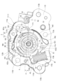
- FIG. 2 is a plan view of the pump main body with the second housing shown in FIG. 1 omitted;
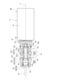
- FIG. 2 is a longitudinal cross-sectional view of a control valve of a variable displacement oil pump according to the present invention.
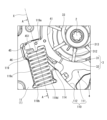
- FIG. 2 is an enlarged view of the main part of FIG. 1.
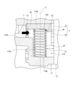
- FIG. FIG. 4 is a cross-sectional view taken along the line AA in FIG. 3.
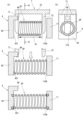
- FIG. 2 is a diagram illustrating a method for manufacturing a variable displacement oil pump according to the present invention, in which (a) is a schematic diagram for explaining a coil spring arrangement process, and (b) is a cross section taken along line BB in FIG. It is a diagram.
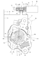
- FIG. 3 is a diagram showing the operating state of the variable displacement oil pump according to the present invention, and is a diagram showing the operating state in which the amount of eccentricity of the cam ring is the largest.
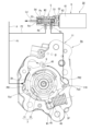
- FIG. 3 is a diagram showing the operating state of the variable displacement oil pump according to the present invention, and is a diagram showing the operating state in which the amount of eccentricity of the cam ring is the smallest.
- variable displacement oil pump is applied as an oil pump for supplying lubricating oil to an internal combustion engine for an automobile.
- axial direction the direction along the rotation axis of the drive shaft 2
- radial direction the direction orthogonal to the rotation axis of the drive shaft 2
- the rotation direction of the drive shaft 2 is referred to as the "circumferential direction.” ” is defined and explained.
- FIG. 1 shows an exploded perspective view of a pump main body PA of a variable displacement oil pump according to this embodiment.
- FIG. 2 shows a plan view of the pump main body PA with the second housing 12 shown in FIG. 1 removed.
- the variable displacement oil pump includes a pump body PA and a control valve SV (see FIG. 3) that controls the discharge amount (discharge pressure) of the pump body PA.
- the pump body PA includes a drive shaft 2, a pump element 3 rotationally driven by the drive shaft 2, a cam ring 4 swingably provided on the outer circumferential side of the pump element 3, and a coil spring SP that biases the cam ring 4. These are housed inside the housing 1.
- the pump main body PA is fastened to an engine (not shown), specifically to a side of a cylinder block (not shown), by a bolt (not shown).
- the housing 1 includes a cup-shaped first housing 11 corresponding to a pump body, and a cover member that is joined to the first housing 11 and closes an opening of the first housing 11. and a corresponding second housing 12.
- the first housing 11 and the second housing 12 are fastened together by a screw SW while being positioned by a positioning pin PN.
- the first housing 11 and the second housing 12 are both integrally formed of a metal material, for example, an aluminum alloy.
- the first housing 11 has a bottom wall 111 and a peripheral wall 112 that rises from the outer periphery of the bottom wall 111 and continues in the circumferential direction along the outer periphery of the bottom wall 111. That is, the first housing 11 is open at one end in the axial direction facing the second housing 12, and the other end is closed by the bottom wall 111. In other words, the bottom wall 111 and the peripheral wall 112 define a cup-shaped pump accommodating portion 110 inside the first housing 11 .
- a joint surface 113 for joining with the second housing 12 is provided at the opening edge of the first housing 11 on one axial end side.
- This joint surface 113 is provided so as to extend outward in the radial direction of the first housing 11, and is formed integrally with the peripheral wall 112.
- a plurality of (two in this embodiment) female screw holes 113a are formed in the joint surface 113.
- the plurality of female threaded holes 113a are provided at intervals in the circumferential direction, and a plurality of screws SW for fastening the second housing 12 to the first housing 11 are screwed into each female threaded hole 113a.
- a plurality (four in this embodiment) of first housing side attachment holes 113b are formed in the joint surface 113.
- the plurality of first housing side mounting holes 113b are provided at intervals in the circumferential direction, and together with the second housing side mounting holes 121b provided in the second housing 12, the variable displacement oil pump is attached to a cylinder block (not shown). Configure the pump mounting hole for installation.
- a first bearing hole (not shown) that rotatably supports one end of the drive shaft 2 passes through the bottom wall 111 that constitutes one end wall of the pump accommodating portion 110 at a substantially central position. Further, on the inner surface of the bottom wall 111, on the outer peripheral side of the first bearing hole (not shown), there is a region (hereinafter referred to as "suction A first suction port 114 having a generally arcuate shape is formed so as to open into a region.
- discharge area On the other hand, on the opposite side of the rotation center Z of the drive shaft 2 from the suction area, there is a generally circular shape so as to open into an area where the volume of a plurality of pump chambers 30 (hereinafter referred to as "discharge area") is reduced, which will be described later.
- a first discharge port 115 having an arc shape is formed.
- a first pin support groove 111b is formed on the outer circumferential side of the first discharge port 115 to swingably support the cam ring 4 via a generally cylindrical pivot pin 40. ing. One axial end of the pivot pin 40 is press-fitted into the first pin support groove 111b.
- the first suction port 114 is formed to be narrowest at the starting end, widest at the middle, and gradually contract from the middle to the terminal in the rotational direction D of the drive shaft 2. Further, a suction port extension portion 114a extending radially outward is continuously provided in the intermediate portion of the first suction port 114. Furthermore, the suction port extension 114a is provided with a suction port 114b (see FIG. 5) that penetrates the bottom wall 111 and opens to the outside. Reserved oil is introduced. Note that the suction port 114b may be directly opened to the unillustrated oil pan via an unillustrated oil strainer, or may be connected to the unillustrated oil pan via an unillustrated suction passage. .
- the suction portion is composed of the suction port 114b, the first suction port 114, and the second suction port 124, which will be described later.
- the first discharge port 115 gradually expands from the starting end toward the intermediate portion and gradually decreases from the intermediate portion toward the terminal end in the rotation direction D of the drive shaft 2. is formed. Further, the first discharge port 115 is provided with a discharge port (not shown) that penetrates the bottom wall 111 and opens to the outside.
- variable displacement oil pump is pressurized by the pump action of the pump element 3 and discharged to the first discharge port 115 and the second discharge port 125, which will be described later.
- Oil is supplied from the discharge port (not shown) to the main gallery provided inside the cylinder block (not shown), and to each sliding part (for example, a crank metal) of the engine (not shown) and the piston of the engine (not shown).
- the oil is supplied to an oil jet device (not shown) for cooling the engine, a valve timing control device (not shown), and the like.
- a discharge portion is configured by the first discharge port 115, the second discharge port 125, which will be described later, and the discharge port (not shown).
- a communication groove (not shown) is provided in the bottom wall 111 of the first housing 11 to connect the first discharge port 115 and the first bearing hole (not shown). That is, through this communication groove, oil is supplied to the first bearing hole (not shown) and also to the sides of the rotor 31 and each vane 32, which will be described later, to ensure good lubrication of each sliding part. It is secured. Note that this communication groove is formed so as not to coincide with the direction in which each vane 32, which will be described later, appears and retracts, thereby suppressing each vane 32 from falling into the communication groove.
- the peripheral wall 112 that constitutes the side wall of the pump accommodating portion 110, there are a center Z of the first bearing hole 111a, which is the rotation center of the drive shaft 2, and a first pin support groove 111b, which is the swing center of the cam ring 4.
- the first seal member S1 and the second seal member S2 provided on the outer circumferential side of the cam ring 4 slide on the upper side of FIG.
- a first seal sliding contact surface 112a and a second seal sliding contact surface 112b that can be contacted are formed.
- the first seal sliding contact surface 112a is formed in an arcuate shape having a curvature configured with a first radius R1 from the center Q of the first pin support groove 111b, and the first seal member is in the swing range of the cam ring 4.
- the second seal sliding contact surface 112b is formed in an arcuate shape having a curvature with a second radius R2 from the center Q of the first pin support groove 111b, and has a second radius R2 from the center Q of the first pin support groove 111b.
- the length in the circumferential direction is set to allow sliding contact between the two seal members S2.
- a third seal sliding contact surface 112c is formed below the cam ring reference line M in FIG. 2, on which the third seal member S3 provided on the outer peripheral side of the cam ring 4 can slide.
- the third seal sliding contact surface 112c is formed in an arcuate shape having a curvature configured with a third radius R3 from the center Q of the first pin support groove 111b. The length in the circumferential direction is set such that S3 can be slidably contacted.
- the second housing 12 functions as a cover member that closes the opening (pump accommodating part 110) of the first housing 11, and connects the joint surface of the first housing 11 with the screw SW. 113.
- the second housing 12 has a screw through hole 121a provided at a position corresponding to the female threaded hole 113a of the first housing 11.
- the second housing 12 is fastened to the first housing 11 by screwing the screw SW passing through the screw through hole 121a into the female threaded hole 113a of the first housing 11.
- a second bearing hole 122a that rotatably supports the other end of the drive shaft 2 is formed in the second housing 12 at a position opposite to the first bearing hole 111a of the first housing 11.
- a second suction port 124 and a second discharge port 125 corresponding to the first suction port 114 and the first discharge port 115 of the first housing 11 are provided on the inner surface of the second housing 12. It is arranged opposite to the first discharge port 115.
- a second pin support groove 122b is formed on the inner surface of the second housing 12 at a position facing the first pin support groove 111b. The second pin support groove 122b press-fits and holds the other end of the pivot pin 40 in the axial direction, and supports the pivot pin 40 in cooperation with the first pin support groove 111b.
- the drive shaft general portion 21 of the drive shaft 2 formed at one end in the axial direction is rotatably supported in the first bearing hole 111a of the first housing 11.
- a drive shaft large diameter portion 22 having an outer diameter larger than the drive shaft general portion 21 at the other end in the axial direction is rotatably supported in the second bearing hole 122a of the second housing 12.
- Ru is linked to the crankshaft of an engine (not shown) via a transmission member.
- a straight line N (hereinafter referred to as "cam ring eccentric direction line") passing through the rotation center Z of the drive shaft 2 and perpendicular to the cam ring reference line M shown in FIG. 2 is the boundary between the suction area and the discharge area. It has become.
- the pump element 3 includes a generally cylindrical rotor 31 that is housed on the inner circumferential side of the cam ring 4 and is rotationally driven by the drive shaft 2, and a radially opening on the outer circumferential side of the rotor 31.
- a plurality of vanes 32 are housed in a plurality of slits 312 so as to be retractable.
- a pair of ring members 33, 33 which are formed to have a smaller diameter than the rotor 31 and are accommodated inside each vane 32 in the radial direction, are arranged at both ends of the rotor 31 in the axial direction.
- the rotor 31 has a generally circular shaft through hole 311 that passes through the center in the axial direction and through which the drive shaft general portion 21 passes. Further, the rotor 31 has a plurality of slits 312 cut out radially from the center side of the shaft through hole 311 toward the outside in the radial direction. Further, at the bottom of each slit 312, a back pressure chamber 313 having a substantially circular cross section is provided for introducing oil. That is, each vane 32 is pushed outward (toward the cam ring 4 side) by the centrifugal force generated as the rotor 31 rotates and the pressure of the oil introduced into the back pressure chamber 313. .
- the plurality of vanes 32 housed in the rotor 31 are formed into a rectangular plate shape from a predetermined metal material, and as the rotor 31 rotates, the tip surface of each vane 32 becomes the inner circumferential surface of the cam ring 4 (described later). (peripheral wall of the pump element accommodating portion 41). That is, since the tip surfaces of each vane 32 are in sliding contact with the inner circumferential surface of the cam ring 4, the rotation direction D of the rotor 31 is controlled by the rotor 31, the pair of vanes 32, 32 adjacent to each other in the circumferential direction, and the cam ring 4.
- a plurality of pump chambers 30 are defined.
- each vane 32 has its base end surface slidingly contacted with the outer peripheral surfaces of the pair of ring members 33, 33, and is pushed up toward the outside in the radial direction of the rotor 31 by the pair of ring members 33, 33.
- the configuration is as follows. As a result, even when the engine speed is low and the centrifugal force accompanying the rotation of the rotor 31 and the hydraulic pressure in the back pressure chamber 313 are small, the tip surface of each vane 32 can slide into contact with the inner circumferential surface of the cam ring 4.
- Each pump chamber 30 is partitioned off in a liquid-tight manner.
- the cam ring 4 is formed of a sintered material into a generally annular shape, and has a circular pump element accommodating portion 41 in which the pump element 3 can be accommodated on the inner peripheral side. Further, on the outer peripheral side of the cam ring 4, an arcuate groove-shaped swinging support part 42 that can slide on the outer peripheral surface of a cylindrical pivot pin 40 supported by the housing 1 is provided along the axial direction. . That is, the cam ring 4 slides into the outer circumferential surface of the pivot pin 40 supported by the first pin support groove 111b and the second pin support groove 122b, and thereby swings into the pump housing section 110 via the pivot pin 40. movably supported. Further, the swing support portion 42 is pressed against the pivot pin 40 by the discharge pressure P acting on the inner surface of the cam ring 4 (pump element accommodating portion 41) in the discharge region due to the pump action by the pump element 3.
- a first seal component 431 which faces the first seal sliding surface 112a, the second seal sliding surface 112b, and the third seal sliding surface 112c of the first housing 11, respectively; It has a second seal component 432 and a third seal component 433.
- the first seal component 431 has a first seal surface 431a that is arcuate and concentric with the first seal sliding surface 112a.
- the second seal component 432 has a second seal surface 432a that is concentric with the second seal sliding surface 112b.
- the third seal component 433 has a third seal surface 433a that is concentric with the third seal sliding surface 112c.
- a first seal holding groove 431b that extends along the axial direction is formed in the first seal surface 431a so as to open toward the first seal sliding surface 112a.
- a second seal holding groove 432b is formed in the second seal surface 432a and extends along the axial direction so as to open toward the second seal sliding surface 112b.
- a third seal holding groove 433b is formed in the third seal surface 433a and extends along the axial direction so as to open toward the third seal sliding surface 112c.
- the first seal holding groove 431b accommodates a first seal member S1 that comes into sliding contact with the first seal sliding contact surface 112a when the cam ring 4 swings.
- the second seal holding groove 432b accommodates a second seal member S2 that slides into contact with the second seal sliding surface 112b when the cam ring 4 swings.
- the third seal holding groove 433b accommodates a third seal member S3 that slides into contact with the third seal sliding contact surface 112c when the cam ring 4 swings.
- the first seal member S1, the second seal member S2, and the third seal member S3 are all made of, for example, a fluororesin material having low friction characteristics, and are made of a fluorine-based resin material that extends along the axial direction of the cam ring 4. It is formed into an elongated straight line. Further, as shown in FIG. 4, elastic members BR made of rubber are arranged at the bottoms of the first seal holding groove 431b, the second seal holding groove 432b, and the third seal holding groove 433b, respectively.
- first, second, and third seal members S1, S2, and S3 elastically contact the first, second, and third seal sliding surfaces 112a, 112b, and 112c, respectively, with the elastic force of the elastic member BR.
- first, second, and third seal surfaces 431a, 432a, and 433a and the first, second, and third seal sliding surfaces 112a, 112b, and 112c are sealed liquid-tightly.
- a first control oil chamber PR1 is defined on the outer peripheral side of the cam ring 4, the first seal member S1 that slides on the first seal sliding contact surface 112a and the second seal member S2 that slides on the second seal sliding contact surface 112b.
- the first control oil pressure P1 is guided to the first control oil chamber PR1 via one of the first passages L1 that is bifurcated from the discharge pressure introduction passage Lb connected to the main gallery. Note that the first control oil pressure P1 guided to the first control oil chamber PR1 is substantially the same as the discharge pressure P guided to the main gallery.
- first passage L1 is connected to a first control pressure introduction hole 118 penetrating the bottom wall 111 of the first housing 11, and the first control pressure P1 is supplied to the first control pressure through the first control pressure introduction hole 118. It is directly introduced into the control oil chamber PR1.
- the first control oil pressure P1 guided to the first control oil chamber PR1 is applied to the first seal component 431 and the second seal component 432 on the outer peripheral surface of the cam ring 4 facing the first control oil chamber PR1. It acts on the first pressure receiving surface 441 formed between.
- the eccentricity ⁇ of the cam ring 4 decreases with respect to the cam ring 4 (hereinafter referred to as A moving force (swinging force) is applied in the "concentric direction").
- a second control oil chamber PR2 is defined on the outer peripheral side of the cam ring 4 by a swing support portion 42 that slides on the pivot pin 40 and a second seal member S2 that slides on the second seal sliding surface 112b. has been done.
- the second control oil pressure P2 is introduced into the second control oil chamber PR2 from the other second passage L2 branched from the discharge pressure introduction passage Lb through the control valve SV. Further, in the second passage L2, the second control oil pressure P2 is introduced into the second control oil chamber PR2 via a second control pressure introduction hole (not shown) that penetrates the second housing 12.
- the second control oil pressure P2 guided to the second control oil chamber PR2 is applied to the swing support portion 42 and the third seal component 433 on the outer peripheral surface of the cam ring 4 facing the second control oil chamber PR2. It acts on the second pressure receiving surface 442 formed between. Due to the hydraulic pressure acting on the second pressure receiving surface 442, the eccentricity ⁇ of the cam ring 4 (the eccentricity of the center O of the pump element accommodating portion 41 with respect to the rotation center Z of the drive shaft 2) increases with respect to the cam ring 4 (hereinafter referred to as A moving force (swinging force) is applied in the "eccentric direction").
- the coil spring SP is housed in a spring accommodating portion 119 provided at a position facing the pivot pin 40 with the rotation center Z of the drive shaft 2 interposed therebetween. That is, a coil spring SP compressed with a predetermined preload (set load W1) is loaded into the spring housing portion 119 between the arm portion 45 extending toward the outer circumferential side of the cam ring 4 and one end wall 119a of the spring housing portion 119. be done.
- the spring accommodating portion 119 is formed in the first housing 11 on the outer peripheral side of the first suction port 114 by recessing the peripheral wall 112 of the pump accommodating portion 110 radially outward.
- one end wall 119a functions as a seating surface for the coil spring SP, while the other end wall 119b functions as a stopper for regulating the movement range of the cam ring 4 in the eccentric direction. That is, the cam ring 4 is always biased in the eccentric direction by the coil spring SP, and the maximum eccentric state is maintained by the arm portion 45 coming into contact with the other end wall 119b of the spring housing portion 119. .
- FIG. 3 shows a longitudinal sectional view of the control valve SV that controls the discharge amount (discharge pressure) of the variable displacement oil pump (pump main body PA) according to the present embodiment.
- the control valve SV is a solenoid valve that is driven and controlled by a control device (not shown) that controls the engine.
- the control valve SV includes a valve section 5 that controls the opening and closing of the second passage L2, and is provided at one end of the valve section 5 and controls the valve section 5 based on an excitation current output by a control device not shown. and a solenoid section 6 for controlling the opening and closing of.
- the valve portion 5 is a so-called three-way valve that includes a valve case 51, a spool valve body 52, a retainer member 53, and a valve spring 54.
- the valve portion 5 may be built into the housing 1 and provided integrally with the variable displacement oil pump, or may be provided separately and independently from the variable displacement oil pump. good.
- the valve case 51 is made of a metal material, for example, an aluminum alloy material, and has a generally cylindrical shape with both ends open in the direction of the central axis Y, and has a valve body housing portion 510 inside.
- the valve body accommodating portion 510 is constituted by a stepped through hole that penetrates the valve case 51 along the central axis Y direction of the valve case 51. That is, this valve body accommodating portion 510 has a first valve body sliding contact portion 511 on one end side in the central axis Y direction, and has a first valve body sliding contact portion 511 on the other end side in the central axis Y direction.
- the second valve body sliding contact portion 512 also has a large diameter.
- the opening of the valve body accommodating portion 510 on the first valve body sliding contact portion 511 side is closed by the solenoid portion 6 .
- the opening on the second valve body sliding contact portion 512 side of the valve body accommodating portion 510 functions as a drain port Pd for discharging oil from the spring accommodating chamber 55, which will be described later, and opens into the drain passage Ld.
- the drain port Pd may not open to the drain passage Ld, but may directly open to an oil pan (not shown) corresponding to a low pressure section.
- the drain port Pd only needs to be in communication with a low-pressure part, and in addition to a configuration in which it communicates with an oil pan (not shown) corresponding to atmospheric pressure, it may also be in a configuration in which it communicates with, for example, the vicinity of the suction port 114b, which has a negative pressure.
- the end on the first valve body sliding contact part 511 side (the right side in FIG. 3) is defined as the first end, and the end on the second valve body sliding contact part 512 side ( The left end in FIG. 3 will be defined as the second end.
- a first annular groove 513 is formed on the outer peripheral side of the first valve body sliding contact portion 511 by cutting out the outer peripheral surface of the valve case 51 along the circumferential direction. Furthermore, a plurality of first valve holes 513a are formed at the bottom of the first annular groove 513, which communicate between the inside and outside of the valve body housing portion 510 in the radial direction of the valve case 51 perpendicular to the central axis Y.
- the first valve hole 513a is constituted by a round hole that is generally circular in plan view, and serves as a supply/discharge port Pc for supplying and discharging oil (second control oil pressure P2) to and from the second control oil chamber PR2 through the second passage L2. Function.
- a second annular groove 514 is formed on the outer peripheral side of the second valve body sliding contact portion 512 by cutting out the outer peripheral surface of the valve case 51 along the circumferential direction.
- a second valve hole 514a is formed at the bottom of the second annular groove 514, which communicates between the inside and outside of the valve body accommodating portion 510 in the radial direction of the valve case 51 perpendicular to the central axis Y.
- the second valve hole 514a is constituted by a round hole that is generally circular in plan view, and functions as an introduction port Pb that introduces oil (discharge pressure P) from the discharge pressure introduction passage Lb.
- the spool valve body 52 has a stepped cylindrical shape with different outer diameters in the central axis Y direction, which is the direction of movement, and is slidably accommodated in the valve body accommodating portion 510 of the valve case 51.
- the spool valve body 52 has a first land portion 521 that is in sliding contact with the first valve body sliding contact portion 511, and is formed to have a larger diameter than the first land portion 521, and a second valve body sliding contact portion 512. and a second land portion 522 that is in sliding contact with the second land portion 522 .
- an intermediate shaft portion 523 having an outer diameter smaller than those of the first land portion 521 and the second land portion 522 is formed between the first land portion 521 and the second land portion 522. That is, the intermediate shaft portion 523 defines a relay chamber Rc between the intermediate shaft portion 523 and the valve body housing portion 510 in the radial direction of the valve case 51.
- the first land portion 521 and the second land portion 522 facing each other in the direction of the central axis Y function as a pressure receiving surface that receives the hydraulic pressure guided from the second valve hole 514a.
- the second land portion 522 has a relatively large outer diameter with respect to the first land portion 521, and the second land portion 522 has a relatively large outer diameter with respect to the first pressure receiving surface Pf1 constituted by the first land portion 521.
- the second pressure receiving surface Pf2 is formed to be relatively large.
- the hydraulic pressure introduced into the relay chamber Rc from the second valve hole 514a is relatively larger than that of the first pressure receiving surface Pf1.
- the spool valve body 52 is pressed toward the second end.
- the spool valve body 52 has a shaft end portion 524 having an outer diameter smaller than the first land portion 521 on the first end side of the first land portion 521 .
- the shaft end portion 524 defines a back pressure chamber Rb between the shaft end portion 524 and the valve body housing portion 510 in the radial direction of the valve case 51 .
- the back pressure chamber Rb collects oil leaked from the relay chamber Rc through the outer peripheral side of the first land portion 521 (a minute gap with the valve body housing portion 510).
- the back pressure chamber Rb includes a discharge hole 525 formed in the peripheral wall of the first end of the spool valve body 52 facing the back pressure chamber Rb, and an internal passage 526 that connects the discharge hole 525 with a spring accommodation chamber 55, which will be described later. It communicates with the spring housing chamber 55 through . That is, the oil collected in the back pressure chamber Rb is led to the spring storage chamber 55, which will be described later, through a discharge hole 525 and an internal passage 526, and is discharged to an oil pan (not shown) through a drain port Pd and a drain passage Ld. be done.
- the spool valve body 52 has a spring support portion 527 that supports the first end of the valve spring 54 facing the spool valve body 52 at the end on the second land portion 522 side facing the retainer member 53.
- the spring support portion 527 is formed by expanding the diameter of the inner peripheral side of the spool valve body 52 in a stepped manner toward the second land portion 522 side, and includes a cylindrical spring surrounding portion 527a and a flat spring support portion. It has a surface 527b.
- the spring support portion 527 supports the first end of the valve spring 54 with the spring support surface 527b while surrounding the outer peripheral side of the first end of the valve spring 54 with the spring surrounding portion 527a.
- the retainer member 53 has an annular spring seat 531 that supports the second end of the valve spring 54 and a circular retainer opening 530 that passes through the center of the spring seat 531. That is, the outer peripheral edge of this retainer member 53 is fitted into the opening end on the second end side of the valve case 51, and the spring seating part 531 supports the second end of the valve spring 54, and the retainer opening 530 connects the second valve hole 514a and the drain port Pd.
- the valve spring 54 is a well-known compression coil spring, and is loaded into a spring housing chamber 55 defined between the spool valve body 52 and the retainer member 53 with a predetermined preload (set load W2). Thereby, the valve spring 54 constantly biases the spool valve body 52 toward the first end based on the set load W2.
- the solenoid section 6 is provided with a cylindrical casing 61, a coil (not shown) and an armature housed inside the casing 61, and is fixed to the armature and movable back and forth along the central axis Y direction together with the armature. and a rod 62.
- an excitation current is supplied to the solenoid section 6 from a control device (not shown) based on the operating state of the engine detected or calculated based on predetermined parameters such as engine oil temperature, water temperature, and engine rotation speed (not shown).
- the solenoid section 6 can continuously change the magnitude of the electromagnetic force Fm according to the supplied current value, is controlled by pulse width modulation (PWM), and the current value is given by the duty ratio.
- PWM pulse width modulation
- FIG. 4 shows an enlarged view of the main part of FIG. 1, showing the vicinity of the coil spring SP accommodated in the spring housing portion 119 of FIG. 1. Further, FIG. 5 shows a cross-sectional view taken along the line AA in FIG. 3 taken along the line AA in FIG.
- a A generally rectangular concave spring accommodating portion 119 is formed to open at the joint surface 113 of the first housing 11 .
- the arm portion 45 of the cam ring 4 housed in the pump housing portion 110 faces the spring housing portion 119, and the cam ring 4 is biased eccentrically between the arm portion 45 and the spring housing portion 119.
- a coil spring SP is compressed by a predetermined amount and housed with a predetermined preload (set load W1).
- the spring housing portion 119 has a generally rectangular shape in plan view, and is set to a depth such that the center X of the coil spring SP is located approximately at the center of the axial width (Z-axis width) of the cam ring 4. Because of this configuration, in this embodiment, as shown in FIG. A predetermined gap C1 is formed between the two.
- the spring accommodating portion 119 has one end wall 119a formed on one end side in the X-axis direction that contacts the arm portion 45 of the cam ring 4, and is provided so as to face this one end wall 119a, and contacts the coil spring SP.
- the other end wall 119b is formed on the other end side in the X-axis direction.
- the one end wall 119a contacts the arm portion 45 of the cam ring 4 to restrict the maximum eccentricity of the cam ring 4.
- the other end wall 119b contacts the coil spring SP and supports the coil spring SP.
- the spring housing portion 119 has an outer regulating wall 119c that corresponds to a first regulating wall that can support the outer side of the coil spring SP and regulate the displacement of the coil spring SP toward the outside in the radial direction.
- the spring accommodating portion 119 is located on the opposite side of the outer regulating wall 119c across the X-axis corresponding to the center of the outer diameter of the coil spring SP, and on the radially inner side with respect to the end of the coil spring SP on the other end wall 119b side. It has an inner regulating wall 119d that can regulate the positional shift of the coil spring SP toward.
- the spring accommodating part 119 is configured by the bottom wall of the spring accommodating part 119 on the opposite side of the protrusion 46 with the X axis in between, and the coil spring SP is arranged on the opposite side of the protrusion 46 in the axial direction of the coil spring SP. It has a bottom side regulating wall 119e corresponding to a third regulating wall on which positional deviation can be recorded.
- the arm portion 45 of the cam ring 4 also has a spring contact surface 451 that is a contact surface with the coil spring SP at the end of the first housing 11 on the joint surface 113 side in the longitudinal direction of the coil spring SP (X-axis A protrusion 46 is provided that extends in the direction) and overlaps a part of the outer periphery of the coil spring SP.
- the protrusion 46 is formed integrally with the arm portion 45 and has a prismatic shape with a generally rectangular cross section, and is not annular so as to cover the entire circumference of the end of the coil spring SP on the arm portion 45 side. It is formed so as to overlap only a part of the circumferential region at the end portion on the side of the portion 45 .
- the protrusion 46 is provided so as to be spaced apart from the coil spring SP disposed inside, and is configured to form a small gap C2 between the protrusion 46 and the coil spring SP in an upright state.
- the protrusion 46 be provided on the side where the coil spring SP is likely to tilt due to the flow of oil, that is, at a position downstream of the coil spring SP in the flow of oil led from the suction port 114b.
- the protrusion 46 is located on the joint surface 113 side of the first housing 11 in the arm portion 45, which corresponds to the downstream side of the oil flow led from the suction port 114b (see arrow F in FIG. 5). Preferably located at the end.
- the protrusion 46 can be placed at any position where the tilting of the coil spring SP can be regulated, depending on the situation in which the coil spring SP is tilted.
- the protrusion 46 when the protrusion 46 is provided at the end of the first housing 11 on the joint surface 113 side, the protrusion 46 must be provided at a position that overlaps with the center of the outer diameter (X axis) of the coil spring SP. is desirable. Further, in this embodiment, a single protrusion 46 is disposed, but a plurality of protrusions 46 may be disposed as necessary, such as when the coil spring SP is tilted.
- the outer peripheral side of the cam ring 4 has a flat surface shape that is approximately parallel to the outer regulating wall 119c of the first housing 11 in the maximum eccentric state of the cam ring 4 shown in FIG. 4, and supports the outer side of the coil spring SP.
- a cam ring regulating wall 47 is formed which corresponds to a second regulating wall capable of regulating radially inward positional deviation of the coil spring SP.
- FIGS. 6A and 6B are diagrams illustrating the manufacturing method of the variable displacement oil pump according to the present embodiment, in which (a) is a schematic diagram for explaining the coil spring arrangement process, and (b) is a diagram similar to the one shown in FIG. A cross-sectional view taken along the line BB is shown.
- This jig 7 includes a connection base 70 formed in a rectangular plate shape, a first holding part 71 formed in a bifurcated shape (U-shaped in plan view) through a notch 710, and a first holding part 71 formed in a bifurcated shape (U-shaped in plan view).
- a pair of spring holding parts are provided in which a second holding part 72 in a flat plate shape is provided so as to face parallel to each other, and the first holding part 71 and the second holding part 72 are configured to be movable relative to each other.
- the coil spring SP is compressed by sandwiching the coil spring SP between the parts 72 and making the interval Cx between the first holding part 71 and the second holding part 72 narrower than the free length of the coil spring SP.
- the coil spring SP compressed by the jig 7 is connected to the other end wall 119b of the spring accommodating part 119 and the arm part 45.
- the jig is held while the coil spring SP is held in a compressed state between the first holding part 71 and the second holding part 72 of the jig 7. Insert the jig 7 between the other end wall 119b of the spring accommodating portion 119 and the arm portion 45 from the joint surface 113 side of the first housing 11 through the notch 710 of the cam ring 4 while avoiding the protrusion 46 of the cam ring 4. .
- the first holding part 71 and the second holding part of the jig 7 are inserted between the other end wall 119b of the spring accommodating part 119 and the arm part 45 via an extrusion mechanism (not shown) provided in the jig 7.
- 72 in a compressed state is pushed out in the direction shown by the arrow (see middle row of FIG. 6(a)).
- this extruded coil spring SP expands due to the restoring force based on the compression, and one end elastically contacts the spring contact surface 451 of the arm portion 45, and the other end contacts the other end wall of the spring accommodating portion 119. 119b, and the assembly of the coil spring SP is completed (see the lower part of FIG. 6(a)).
- FIG. 7 shows an operating state in which the amount of eccentricity of the cam ring 4 is greatest among the operating states of the variable displacement oil pump.
- FIG. 8 shows an operating state in which the amount of eccentricity of the cam ring 4 is the smallest among the operating states of the variable displacement oil pump.
- variable displacement oil pump in the variable displacement oil pump according to the present embodiment, rotation of a crankshaft (not shown) is transmitted to a drive shaft 2 via a chain (not shown).
- the rotor 31 is rotationally driven in the rotation direction D. Then, as the rotor 31 rotates, oil is sucked up from an oil pan (not shown) through the suction port 114b, the first suction port 114, and the second suction port 124. Simultaneously with this suction action, the oil in each pump chamber 30 located in the discharge region is discharged to a discharge passage (not shown) via the first discharge port 115, second discharge port 125, and discharge port 115a.
- the oil discharged into this discharge passage is then forced through the main gallery to the engine's sliding parts (for example, crank metal) not shown, an oil jet device not shown, a valve timing control device not shown, etc. At the same time, it is guided to the first passage L1 and the second passage L2 via the discharge pressure introduction passage Lb connected to the main gallery.
- an oil pressure sensor (not shown) capable of detecting the discharge pressure P is arranged on the main gallery, and the detection result of this oil pressure sensor is fed back to a control device (not shown).
- the eccentricity ⁇ (see FIG. 2), which is the difference between the rotation center Z of the drive shaft 2 and the center O of the pump element accommodating portion 41, changes.
- the amount of change in volume of the pump chamber 30 (the difference between the maximum volume and the minimum volume) changes.
- the amount of eccentricity ⁇ increases, the amount of change in the volume of the pump chamber 30 also increases, while as the amount of eccentricity ⁇ decreases, the amount of change in the volume of the pump chamber 30 also decreases.
- the eccentricity ⁇ is determined by the biasing force in the concentric direction based on the internal pressure of the first control oil chamber PR1 (the first control oil pressure P1), the set load W1 of the coil spring SP, and the internal pressure of the second control oil chamber PR2 (the second control oil pressure P1). It changes depending on the biasing force in the eccentric direction based on the control oil pressure P2).
- the first control oil pressure P1 is introduced into the first control oil chamber PR1 via the first passage L1 branched from the discharge pressure introduction passage Lb.
- a biasing force (hydraulic pressure Fp2) becomes smaller than the set load W2 of the valve spring 54.
- the spool valve body 82 is maintained in a state in which it is most displaced toward the first end, and the introduction port Pb and supply/discharge port Pc are communicated (first state).
- a second control oil pressure P2 is introduced into the second control oil chamber PR2.
- the resultant force of the hydraulic pressure Fp2 generated by the second control oil pressure P2 of the second control oil chamber PR2 acting on the second pressure receiving surface 442 and the set load W1 of the coil spring SP is
- the first control hydraulic pressure P1 of PR1 exceeds the hydraulic pressure Fp1 generated by acting on the first pressure receiving surface 441, and the cam ring 4 is maintained in the maximum eccentric state.
- the hydraulic pressure Po of the discharge pressure P is increased while the duty ratio of the excitation current supplied to the solenoid section 6 is 0%. , is larger than the set load W2 of the valve spring 54.
- the spool valve body 52 moves toward the second end, the communication between the introduction port Pb and the supply/discharge port Pc is cut off, and the communication between the supply/discharge port Pc and the drain port Pd is established.
- the oil in the second control oil chamber PR2 is discharged (second state), and the discharge pressure P acts only on the first control oil chamber PR1.
- the spool valve body 52 moves toward the second end based on the increase in the discharge pressure P, and the spool valve body 52 moves toward the second end, causing the cam ring 4 to move toward the second end.
- the movement of the spool valve body 52 toward the first end side as the spool valve body 52 reaches the minimum eccentric state is alternately and continuously repeated. In this way, the state in which the supply/discharge port Pc and the introduction port Pb communicate with each other and the state in which the supply/discharge port Pc and the drain port Pd communicate with each other are alternately and continuously switched, so that the discharge pressure P changes to the engine required oil pressure. will be maintained.
- the operating state of the variable displacement oil pump is illustrated when the engine is started and when the discharge pressure P is high.
- the hydraulic pressure Po of the discharge pressure P is Even when the load is smaller than the set load W2 of the valve spring 54, by adjusting the duty ratio of the excitation current supplied to the solenoid section 6 of the control valve SV, the above-mentioned It is possible to shift to two states, and the discharge pressure P of the variable displacement oil pump can be controlled in multiple stages.
- a generally cylindrical protrusion or recess that surrounds the outer circumferential side of the coil spring is provided on the spring contact surface of the arm portion of the cam ring, and the protrusion or recess is It is also conceivable that by fitting the coil spring on the inner circumferential side, the outer circumferential side of the coil spring is supported by the protrusion or recess, thereby suppressing displacement of the coil spring.
- the compressed coil spring when assembling the coil spring, the compressed coil spring must be fit into the inner circumference of the protrusion or the recess while restoring the coil spring, and the coil spring must be fitted onto the outer circumference of the protrusion. As with the matching mode, there was room for improvement in that it was difficult to assemble the coil spring.
- the difficulty in assembling the coil spring will be specifically explained.
- the coil spring When fitting a coil spring to the outer circumference of a protrusion, or when fitting a coil spring to the inner circumference of a protrusion or recess, the coil spring must be assembled in a compressed state in order to provide preload to the coil spring.
- This jig holds the coil spring in a compressed state between a pair of holding parts arranged opposite to each other, and holds the coil spring between the arm part of the cam ring and the housing (spring accommodating part) together with the pair of holding parts.
- the coil spring By inserting the coil spring between the cam ring and pushing the coil spring out of the pair of holding parts, the coil spring is assembled so as to be pushed between the arm part of the cam ring and the housing (spring accommodating part).
- the coil spring needs to be compressed extra by the thickness of the pair of holding parts that are inserted together with the coil spring between the arm part of the cam ring and the housing (spring accommodating part). For this reason, the restoring force of the coil spring increases by the amount of extra compression, and when the coil spring is pushed out from the jig, the coil spring is released with a larger restoring force, and the coil spring is released from the arm part of the cam ring or the housing ( This results in stronger contact with the spring accommodating portion. As a result, there is a risk that the arm portion of the cam ring or the housing (spring accommodating portion) may be damaged due to the contact of the coil spring.
- the coil spring is released by pushing it out of the jig, it becomes difficult to control the attitude of the coil spring after being pushed out from the jig. Therefore, it is extremely difficult to fit the coil spring to the outer or inner circumference of the protrusion, which has a relatively narrow gap with the coil spring, as described above, and the coil spring assembly process is difficult. They are forced to suffer sexual deterioration. Moreover, since it is difficult to control the posture of the coil spring after it has been released from the jig, there is a risk that the coil spring may be assembled in a tilted state, resulting in poor assembly of the coil spring.
- the protrusion is formed separately from the cam ring as a so-called retainer member, and the retainer member is attached to the inner circumference of the coil spring in advance.
- a possible mode is to assemble the coil spring in a fitted state.
- the number of parts of the variable displacement oil pump increases by forming the protrusion separately as a retainer member. As a result, the manufacturing cost, management man-hours, and assembly man-hours of the retainer member increase, resulting in an increase in the manufacturing cost of the variable displacement oil pump.
- variable displacement oil pump includes a housing 1 (first housing 11) having a pump housing part 110, a cam ring 4 movably housed inside the pump housing part 110, A pump element 3 is rotatably housed inside the cam ring 4 and cooperates with the cam ring 4 to form a plurality of pump chambers 30.
- a coil spring SP biases the cam ring 4 in a direction to increase the amount of eccentricity, and a spring contact surface 451 provided on the cam ring 4 and extending in the longitudinal direction of the coil spring SP from a spring contact surface 451 that the coil spring SP comes into contact with, the outer periphery of the coil spring SP. It has a protrusion 46 that is partially formed so as to overlap a part of the .
- the spring contact surface 451 of the cam ring 4 is provided with the protrusion 46 that is partially formed so as to overlap a part of the outer circumference of the coil spring SP.
- the protrusion 46 can restrict the tilting of the coil spring SP. Thereby, the upright state of the coil spring SP is maintained, and an appropriate biasing force can be applied to the cam ring 4 (arm portion 45).
- the protrusion 46 is partially formed so as to overlap a part of the outer periphery of the coil spring SP, when assembling the coil spring SP, the coil spring SP can be simply pushed inside the protrusion 46. Since it is not necessary to fit the coil spring SP into a protrusion or a recess as in the conventional case, it is possible to easily assemble the coil spring SP.
- the protrusion 46 is partially formed so as to overlap a part of the outer circumference of the coil spring SP, the protrusion 46 can be formed into an annular shape surrounding the outer circumference of the coil spring SP as described above. Compared to the case where the coil spring SP is formed, it becomes possible to visually confirm the assembled state of the coil spring SP from the outside. This makes it possible to easily visually judge whether the coil spring SP is properly assembled, thereby providing efficient quality assurance of the oil pump.
- the protrusion 46 it is also possible to arrange the protrusion 46 not on the cam ring 4 but on the inner surface of the second housing 12 that closes the spring accommodating portion 119.
- the inner surface of the second housing 12 is finished by machining, if the protrusion 46 is provided on the inner surface of the second housing 12, the protrusion 46 should be avoided when machining the inner surface of the second housing 12. This is not appropriate because it may lead to a decrease in productivity and an increase in manufacturing costs for variable displacement oil pumps.
- the housing 1 (first housing 11) has a first coil spring SP that restricts movement of the coil spring SP toward the outside in the radial direction perpendicular to the rotation axis Z of the pump element 3.
- the cam ring 4 has a regulating wall (outer regulating wall 119c), and the cam ring 4 has a second regulating wall (cam ring regulating wall 47) that regulates the movement of the coil spring SP toward the inside in the radial direction perpendicular to the rotation axis Z of the pump element 3. has.
- the outer regulating wall 119c is the first regulating wall provided in the spring accommodating portion 119 of the housing 1 (first housing 11), and the second regulating wall is provided in the cam ring 4.
- the cam ring regulating wall 47 makes it possible to regulate the displacement of the coil spring SP. Thereby, in cooperation with the protrusion 46, it is possible to effectively suppress the occurrence of tilting of the coil spring SP.
- the protrusion 46 is provided in a single piece.
- the single protrusion 46 when assembling the coil spring SP, for example, the first holding part 71 formed in a bifurcated shape by the notch 710 and the flat second holding part 71 can be assembled.
- the protrusion 46 is held by the notch 710 while the coil spring SP is compressed and held between the first holding part 71 and the second holding part 72.
- the coil spring SP can be assembled between the cam ring 4 (spring contact surface 451 of the arm portion 45) and the housing 1 (the other end wall 119b of the spring accommodating portion 119 of the first housing 11) while avoiding this. Thereby, the workability of assembling the coil spring SP can be improved.
- the protrusion 46 is disposed in the middle of the flow of oil led from the suction port 114b, it can act as a resistance to the flow of the oil. Therefore, by providing a single protrusion 46 as in this embodiment, the oil flow resistance is reduced compared to the case where a plurality of protrusions 46 are provided, and the pressure loss of the pump due to the provision of the protrusion 46 is reduced. can be reduced.
- the protrusion 46 is provided at a position overlapping with the center X of the outer diameter of the coil spring SP.
- the protrusion 46 is provided at a position overlapping with the center X of the outer diameter of the coil spring SP, the tilting of the coil spring SP can be appropriately restricted by the protrusion 46 in a well-balanced manner. I can do it. In other words, even if the cam ring 4 swings, the protrusion 46 can appropriately restrict the movement of the coil spring SP.
- the housing 1 (first housing 11) has a third coil spring SP that restricts movement of the coil spring SP to the opposite side in the radial direction with respect to the protrusion 46. It has a regulating wall (cam ring regulating wall 47).
- the cam ring regulating wall 47 as the third regulating wall that regulates the movement of the coil spring SP is provided on the opposite side of the coil spring SP in the radial direction with respect to the protrusion 46.
- the coil spring SP can be sandwiched between the protrusion 46 and the housing 1 (the cam ring regulating wall 47 of the spring accommodating portion 119 of the first housing 11), and the positioning of the coil spring SP can be performed more easily.
- the coil spring SP is disposed in the oil passage leading from the suction port 114b provided in the housing 1 to the pump chamber 30, and the protrusion 46 is arranged in the oil passage. It is arranged downstream of the coil spring SP.
- the protrusion 46 is arranged downstream of the coil spring SP in the suction side oil passage that connects the suction port 114b to the pump chamber 30. Thereby, it is possible to effectively suppress the occurrence of tilting of the coil spring SP due to the flow of oil flowing into the pump chamber 30 from the suction port 114b.
- the method for manufacturing a variable displacement oil pump includes a cam ring arranging step of arranging the cam ring 4 in the pump accommodating portion 110, and a coil spring SP arranging the coil spring SP in the pump accommodating portion 110 after the cam ring arranging step.
- a bifurcated first holding part 71 having a notch 710 in the middle part and capable of holding one end of the coil spring SP, and a second holding part capable of holding the other end of the coil spring SP are formed.
- the coil spring SP is held in a compressed state by the jig 7 having the section 72 , and the jig 7 is inserted between the cam ring 4 and the pump housing section 110 so as to avoid the protrusion 46 by the notch 710 of the first holding section 71 . and arranging the coil spring SP in the pump accommodating portion 110 by inserting the coil spring SP in between.
- the coil spring SP is held in a compressed state by the jig 7 having the bifurcated first holding part 71 and the second holding part 72 in which the notch 710 is formed. 710, the coil spring SP is inserted between the cam ring 4 (spring contact surface 451 of the arm portion 45) and the pump housing part 110 (the other end wall 119b of the spring housing part 119) while avoiding the protrusion 46.
- the configuration is such that SP can be assembled. Therefore, compared to the conventional configuration in which the entire circumference of the coil spring SP is surrounded by the protrusion (or recess), the protrusion 46 can be avoided by the notch 710, and the coil spring SP can be used extra as in the conventional technique.
- Compression eliminates the need to avoid projections 46.
- FIG. 6 it becomes possible to reduce the compression amount of the coil spring SP by the height of the protrusion 46, and the repulsive force of the coil spring SP when the coil spring SP is released from the jig 7 ( resilience) can be reduced.
- errors in assembling the coil spring SP such as the coil spring SP being assembled in a tilted state due to the large repulsion (restoration) of the coil spring SP, are suppressed, and the coil spring SP is properly assembled. Used to ensure proper assembly condition.
- the seating surface of the coil spring SP (specifically, , the spring contact surface 451 of the arm portion 45 of the cam ring 4, and the other end wall 119b of the spring accommodating portion 119) can be prevented from being damaged.
- the present invention is not limited to the configuration disclosed in the above embodiments, and can be freely modified depending on, for example, the specifications of the engine and valve timing control device of the vehicle in which the variable displacement oil pump is mounted.
- the present invention is applied to a vane type variable displacement oil pump, but the variable displacement oil pump to which the present invention can be applied is limited to the vane type oil pump. Instead, it is also possible to apply the present invention to other types of variable displacement oil pumps, such as trochoid type pumps. Note that when the present invention is applied to a trochoidal pump, the outer rotor that constitutes the external gear corresponds to the cam ring.
Landscapes
- Engineering & Computer Science (AREA)
- Mechanical Engineering (AREA)
- General Engineering & Computer Science (AREA)
- Details And Applications Of Rotary Liquid Pumps (AREA)
Abstract
Description
図1は、本実施形態に係る可変容量形オイルポンプのポンプ本体PAの分解斜視図を示している。図2は、図1に示す第2ハウジング12を取り外した状態のポンプ本体PAの平面図を示している。
図3は、本実施形態に係る可変容量形オイルポンプ(ポンプ本体PA)の吐出量(吐出圧)を制御する制御弁SVの縦断面図を示している。
図4は、図1のばね収容部119に収容されるコイルばねSPの近傍を拡大表示した図1の要部拡大図を示している。また、図5は、図3のA-A線に沿って切断した図3のA-A線断面図を示している。
図6は、本実施形態に係る可変容量形オイルポンプの製造方法を説明する図であって、(a)はコイルばね配置工程の説明に供する概略図、(b)は同図(a)のB-B線に沿って切断した断面図を示している。
次に、図7、図8に基づいて、本実施形態に係る可変容量形オイルポンプの動作について説明する。図7は、可変容量形オイルポンプの作動状態のうち、カムリング4の偏心量が最も大きくなる作動状態を示している。図8は、可変容量形オイルポンプの作動状態のうち、カムリング4の偏心量が最も小さくなる作動状態を示している。
前述のように、前記従来の可変容量形オイルポンプでは、カムリングのアーム部のばね当接面から突出する突起部の外周側にコイルばねを嵌合する構成となっている。このため、コイルばねの組み付けに際して、圧縮したコイルばねを復元させつつ前記突起部をコイルばねの内周側に嵌合しなければならず、コイルばねの組み付けが困難となってしまう点で、改善の余地があった。
Claims (8)
- ポンプ収容部を有するハウジングと、
前記ポンプ収容部の内部に移動可能に収容されたカムリングと、
前記カムリングの内周側に回転可能に収容され、前記カムリングと協働して複数のポンプ室を形成するポンプ要素と、
前記ポンプ収容部に配置され、前記ポンプ要素の回転軸に対して前記カムリングの偏心量が増大する方向へ付勢するコイルばねと、
前記カムリングに設けられ、前記コイルばねが当接するばね当接面から前記コイルばねの長手方向に延びて前記コイルばねの外周の一部とオーバーラップするように部分的に形成された突起と、
を有する、ことを特徴とする可変容量形オイルポンプ。 - 請求項1に記載の可変容量形オイルポンプであって、
前記ハウジングは、前記ポンプ要素の回転軸に直交する径方向の外側に向かう前記コイルばねの移動を規制する第1規制壁を有する、
ことを特徴とする可変容量形オイルポンプ。 - 請求項1に記載の可変容量形オイルポンプであって、
前記カムリングは、前記ポンプ要素の回転軸に直交する径方向の内側に向かう前記コイルばねの移動を規制する第2規制壁を有する、
ことを特徴とする可変容量形オイルポンプ。 - 請求項1に記載の可変容量形オイルポンプであって、
前記突起は、単一に設けられている、
ことを特徴とする可変容量形オイルポンプ。 - 請求項1に記載の可変容量形オイルポンプであって、
前記突起は、前記コイルばねの外径の中心と重なる位置に設けられている、
ことを特徴とする可変容量形オイルポンプ。 - 請求項1に記載の可変容量形オイルポンプであって、
前記ハウジングは、前記突起に対して前記コイルばねの径方向の反対側への前記コイルばねの移動を規制する第3規制壁を有する、
ことを特徴とする可変容量形オイルポンプ。 - 請求項1に記載の可変容量形オイルポンプであって、
前記コイルばねは、前記ハウジングに設けられたオイルの吸入口から前記ポンプ室へと繋がる油路に配置され、
前記突起は、前記油路において、前記コイルばねよりも下流側に配置されている、
ことを特徴とする可変容量形オイルポンプ。 - 請求項1に記載の可変容量形オイルポンプの製造方法であって、
前記ポンプ収容部に前記カムリングを配置するカムリング配置工程と、
前記カムリング配置工程の後に前記ポンプ収容部に前記コイルばねを配置するコイルばね配置工程であって、
中間部に切欠きが設けられていて前記コイルばねの一端を保持可能な二股状の第1保持部と、前記コイルばねの他端を保持可能な第2保持部と、を有する治具によって前記コイルばねを圧縮した状態で保持し、前記第1保持部の前記切欠きにより前記突起を避けるように前記治具を前記カムリングと前記ポンプ収容部との間に挿入することをもって前記コイルばねを前記ポンプ収容部に配置する工程と、
を有する、ことを特徴とする可変容量形ポンプの製造方法。
Priority Applications (3)
| Application Number | Priority Date | Filing Date | Title |
|---|---|---|---|
| CN202380061364.8A CN119816667A (zh) | 2022-08-23 | 2023-06-06 | 可变容量型油泵和可变容量型油泵的制造方法 |
| JP2024542597A JP7801466B2 (ja) | 2022-08-23 | 2023-06-06 | 可変容量形オイルポンプ、及び可変容量形オイルポンプの製造方法 |
| US19/105,515 US20260055762A1 (en) | 2022-08-23 | 2023-06-06 | Variable displacement oil pump and method for producing variable displacement oil pump |
Applications Claiming Priority (2)
| Application Number | Priority Date | Filing Date | Title |
|---|---|---|---|
| JP2022-132169 | 2022-08-23 | ||
| JP2022132169 | 2022-08-23 |
Publications (1)
| Publication Number | Publication Date |
|---|---|
| WO2024042811A1 true WO2024042811A1 (ja) | 2024-02-29 |
Family
ID=90012969
Family Applications (1)
| Application Number | Title | Priority Date | Filing Date |
|---|---|---|---|
| PCT/JP2023/020913 Ceased WO2024042811A1 (ja) | 2022-08-23 | 2023-06-06 | 可変容量形オイルポンプ、及び可変容量形オイルポンプの製造方法 |
Country Status (4)
| Country | Link |
|---|---|
| US (1) | US20260055762A1 (ja) |
| JP (1) | JP7801466B2 (ja) |
| CN (1) | CN119816667A (ja) |
| WO (1) | WO2024042811A1 (ja) |
Citations (6)
| Publication number | Priority date | Publication date | Assignee | Title |
|---|---|---|---|---|
| JPH0412180A (ja) * | 1990-05-01 | 1992-01-16 | Toyo A Tec Kk | 可変容量型ベーンポンプ |
| JPH04315585A (ja) * | 1991-04-16 | 1992-11-06 | Ricoh Co Ltd | スプリング保持具 |
| JPH05126065A (ja) * | 1991-10-28 | 1993-05-21 | Toyota Motor Corp | 可変容量型ベーンポンプ |
| US20110300015A1 (en) * | 2010-06-08 | 2011-12-08 | Marco Kirchner | Vane pump |
| JP2016104968A (ja) * | 2014-12-01 | 2016-06-09 | 日立オートモティブシステムズ株式会社 | 可変容量形オイルポンプ |
| US20200300092A1 (en) * | 2017-12-13 | 2020-09-24 | Pierburg Pump Technology Gmbh | Variable lubricant vane pump |
-
2023
- 2023-06-06 US US19/105,515 patent/US20260055762A1/en active Pending
- 2023-06-06 WO PCT/JP2023/020913 patent/WO2024042811A1/ja not_active Ceased
- 2023-06-06 JP JP2024542597A patent/JP7801466B2/ja active Active
- 2023-06-06 CN CN202380061364.8A patent/CN119816667A/zh active Pending
Patent Citations (6)
| Publication number | Priority date | Publication date | Assignee | Title |
|---|---|---|---|---|
| JPH0412180A (ja) * | 1990-05-01 | 1992-01-16 | Toyo A Tec Kk | 可変容量型ベーンポンプ |
| JPH04315585A (ja) * | 1991-04-16 | 1992-11-06 | Ricoh Co Ltd | スプリング保持具 |
| JPH05126065A (ja) * | 1991-10-28 | 1993-05-21 | Toyota Motor Corp | 可変容量型ベーンポンプ |
| US20110300015A1 (en) * | 2010-06-08 | 2011-12-08 | Marco Kirchner | Vane pump |
| JP2016104968A (ja) * | 2014-12-01 | 2016-06-09 | 日立オートモティブシステムズ株式会社 | 可変容量形オイルポンプ |
| US20200300092A1 (en) * | 2017-12-13 | 2020-09-24 | Pierburg Pump Technology Gmbh | Variable lubricant vane pump |
Also Published As
| Publication number | Publication date |
|---|---|
| JPWO2024042811A1 (ja) | 2024-02-29 |
| US20260055762A1 (en) | 2026-02-26 |
| CN119816667A (zh) | 2025-04-11 |
| JP7801466B2 (ja) | 2026-01-16 |
Similar Documents
| Publication | Publication Date | Title |
|---|---|---|
| JP5620882B2 (ja) | 可変容量形ポンプ | |
| USRE46294E1 (en) | Variable displacement pump | |
| JP5688003B2 (ja) | 可変容量形オイルポンプ | |
| JP5564450B2 (ja) | オイルポンプ | |
| CN103321896B (zh) | 叶片泵 | |
| US20140234150A1 (en) | Vane pump | |
| JP6838772B2 (ja) | 可変容量形オイルポンプ | |
| EP3428450B1 (en) | Variable displacement pump | |
| JP4986802B2 (ja) | 可変容量形ポンプ | |
| JP7801466B2 (ja) | 可変容量形オイルポンプ、及び可変容量形オイルポンプの製造方法 | |
| JP6490975B2 (ja) | オイルポンプ | |
| JP7324158B2 (ja) | 可変容量形ポンプ | |
| CN118574999A (zh) | 可变容量型油泵 | |
| WO2023166963A1 (ja) | 可変容量形オイルポンプ | |
| JP7749677B2 (ja) | 可変容量形オイルポンプ | |
| JP7749678B2 (ja) | 可変容量形オイルポンプ | |
| WO2024190001A1 (ja) | 可変容量形オイルポンプ | |
| JP6243262B2 (ja) | 可変容量形ベーンポンプ | |
| JP7630001B2 (ja) | 可変容量形オイルポンプ | |
| JP6543682B2 (ja) | 可変容量形ポンプ | |
| WO2024057753A1 (ja) | 可変容量形ポンプ | |
| WO2020189008A1 (ja) | オイルポンプ |
Legal Events
| Date | Code | Title | Description |
|---|---|---|---|
| 121 | Ep: the epo has been informed by wipo that ep was designated in this application |
Ref document number: 23856929 Country of ref document: EP Kind code of ref document: A1 |
|
| WWE | Wipo information: entry into national phase |
Ref document number: 2024542597 Country of ref document: JP |
|
| WWE | Wipo information: entry into national phase |
Ref document number: 202380061364.8 Country of ref document: CN |
|
| NENP | Non-entry into the national phase |
Ref country code: DE |
|
| WWP | Wipo information: published in national office |
Ref document number: 202380061364.8 Country of ref document: CN |
|
| 122 | Ep: pct application non-entry in european phase |
Ref document number: 23856929 Country of ref document: EP Kind code of ref document: A1 |