WO2024038916A1 - 油化装置及びこれを用いた油化方法 - Google Patents
油化装置及びこれを用いた油化方法 Download PDFInfo
- Publication number
- WO2024038916A1 WO2024038916A1 PCT/JP2023/029905 JP2023029905W WO2024038916A1 WO 2024038916 A1 WO2024038916 A1 WO 2024038916A1 JP 2023029905 W JP2023029905 W JP 2023029905W WO 2024038916 A1 WO2024038916 A1 WO 2024038916A1
- Authority
- WO
- WIPO (PCT)
- Prior art keywords
- oil
- pyrolysis
- gas
- condenser
- water
- Prior art date
- Legal status (The legal status is an assumption and is not a legal conclusion. Google has not performed a legal analysis and makes no representation as to the accuracy of the status listed.)
- Ceased
Links
Images


Classifications
-
- C—CHEMISTRY; METALLURGY
- C10—PETROLEUM, GAS OR COKE INDUSTRIES; TECHNICAL GASES CONTAINING CARBON MONOXIDE; FUELS; LUBRICANTS; PEAT
- C10B—DESTRUCTIVE DISTILLATION OF CARBONACEOUS MATERIALS FOR PRODUCTION OF GAS, COKE, TAR, OR SIMILAR MATERIALS
- C10B47/00—Destructive distillation of solid carbonaceous materials with indirect heating, e.g. by external combustion
- C10B47/28—Other processes
- C10B47/32—Other processes in ovens with mechanical conveying means
- C10B47/34—Other processes in ovens with mechanical conveying means with rotary scraping devices
-
- C—CHEMISTRY; METALLURGY
- C08—ORGANIC MACROMOLECULAR COMPOUNDS; THEIR PREPARATION OR CHEMICAL WORKING-UP; COMPOSITIONS BASED THEREON
- C08J—WORKING-UP; GENERAL PROCESSES OF COMPOUNDING; AFTER-TREATMENT NOT COVERED BY SUBCLASSES C08B, C08C, C08F, C08G or C08H
- C08J11/00—Recovery or working-up of waste materials
- C08J11/04—Recovery or working-up of waste materials of polymers
- C08J11/10—Recovery or working-up of waste materials of polymers by chemically breaking down the molecular chains of polymers or breaking of crosslinks, e.g. devulcanisation
- C08J11/12—Recovery or working-up of waste materials of polymers by chemically breaking down the molecular chains of polymers or breaking of crosslinks, e.g. devulcanisation by dry-heat treatment only
-
- C—CHEMISTRY; METALLURGY
- C10—PETROLEUM, GAS OR COKE INDUSTRIES; TECHNICAL GASES CONTAINING CARBON MONOXIDE; FUELS; LUBRICANTS; PEAT
- C10B—DESTRUCTIVE DISTILLATION OF CARBONACEOUS MATERIALS FOR PRODUCTION OF GAS, COKE, TAR, OR SIMILAR MATERIALS
- C10B53/00—Destructive distillation, specially adapted for particular solid raw materials or solid raw materials in special form
- C10B53/02—Destructive distillation, specially adapted for particular solid raw materials or solid raw materials in special form of cellulose-containing material
-
- C—CHEMISTRY; METALLURGY
- C10—PETROLEUM, GAS OR COKE INDUSTRIES; TECHNICAL GASES CONTAINING CARBON MONOXIDE; FUELS; LUBRICANTS; PEAT
- C10B—DESTRUCTIVE DISTILLATION OF CARBONACEOUS MATERIALS FOR PRODUCTION OF GAS, COKE, TAR, OR SIMILAR MATERIALS
- C10B53/00—Destructive distillation, specially adapted for particular solid raw materials or solid raw materials in special form
- C10B53/07—Destructive distillation, specially adapted for particular solid raw materials or solid raw materials in special form of solid raw materials consisting of synthetic polymeric materials, e.g. tyres
-
- C—CHEMISTRY; METALLURGY
- C10—PETROLEUM, GAS OR COKE INDUSTRIES; TECHNICAL GASES CONTAINING CARBON MONOXIDE; FUELS; LUBRICANTS; PEAT
- C10G—CRACKING HYDROCARBON OILS; PRODUCTION OF LIQUID HYDROCARBON MIXTURES, e.g. BY DESTRUCTIVE HYDROGENATION, OLIGOMERISATION, POLYMERISATION; RECOVERY OF HYDROCARBON OILS FROM OIL-SHALE, OIL-SAND, OR GASES; REFINING MIXTURES MAINLY CONSISTING OF HYDROCARBONS; REFORMING OF NAPHTHA; MINERAL WAXES
- C10G1/00—Production of liquid hydrocarbon mixtures from oil-shale, oil-sand, or non-melting solid carbonaceous or similar materials, e.g. wood, coal
- C10G1/02—Production of liquid hydrocarbon mixtures from oil-shale, oil-sand, or non-melting solid carbonaceous or similar materials, e.g. wood, coal by distillation
-
- C—CHEMISTRY; METALLURGY
- C10—PETROLEUM, GAS OR COKE INDUSTRIES; TECHNICAL GASES CONTAINING CARBON MONOXIDE; FUELS; LUBRICANTS; PEAT
- C10G—CRACKING HYDROCARBON OILS; PRODUCTION OF LIQUID HYDROCARBON MIXTURES, e.g. BY DESTRUCTIVE HYDROGENATION, OLIGOMERISATION, POLYMERISATION; RECOVERY OF HYDROCARBON OILS FROM OIL-SHALE, OIL-SAND, OR GASES; REFINING MIXTURES MAINLY CONSISTING OF HYDROCARBONS; REFORMING OF NAPHTHA; MINERAL WAXES
- C10G1/00—Production of liquid hydrocarbon mixtures from oil-shale, oil-sand, or non-melting solid carbonaceous or similar materials, e.g. wood, coal
- C10G1/10—Production of liquid hydrocarbon mixtures from oil-shale, oil-sand, or non-melting solid carbonaceous or similar materials, e.g. wood, coal from rubber or rubber waste
-
- F—MECHANICAL ENGINEERING; LIGHTING; HEATING; WEAPONS; BLASTING
- F27—FURNACES; KILNS; OVENS; RETORTS
- F27B—FURNACES, KILNS, OVENS OR RETORTS IN GENERAL; OPEN SINTERING OR LIKE APPARATUS
- F27B3/00—Hearth-type furnaces, e.g. of reverberatory type; Electric arc furnaces ; Tank furnaces
- F27B3/10—Details, accessories or equipment, e.g. dust-collectors, specially adapted for hearth-type furnaces
-
- F—MECHANICAL ENGINEERING; LIGHTING; HEATING; WEAPONS; BLASTING
- F27—FURNACES; KILNS; OVENS; RETORTS
- F27D—DETAILS OR ACCESSORIES OF FURNACES, KILNS, OVENS OR RETORTS, IN SO FAR AS THEY ARE OF KINDS OCCURRING IN MORE THAN ONE KIND OF FURNACE
- F27D17/00—Arrangements for using waste heat; Arrangements for using, or disposing of, waste gases
-
- C—CHEMISTRY; METALLURGY
- C10—PETROLEUM, GAS OR COKE INDUSTRIES; TECHNICAL GASES CONTAINING CARBON MONOXIDE; FUELS; LUBRICANTS; PEAT
- C10G—CRACKING HYDROCARBON OILS; PRODUCTION OF LIQUID HYDROCARBON MIXTURES, e.g. BY DESTRUCTIVE HYDROGENATION, OLIGOMERISATION, POLYMERISATION; RECOVERY OF HYDROCARBON OILS FROM OIL-SHALE, OIL-SAND, OR GASES; REFINING MIXTURES MAINLY CONSISTING OF HYDROCARBONS; REFORMING OF NAPHTHA; MINERAL WAXES
- C10G2300/00—Aspects relating to hydrocarbon processing covered by groups C10G1/00 - C10G99/00
- C10G2300/10—Feedstock materials
- C10G2300/1003—Waste materials
-
- Y—GENERAL TAGGING OF NEW TECHNOLOGICAL DEVELOPMENTS; GENERAL TAGGING OF CROSS-SECTIONAL TECHNOLOGIES SPANNING OVER SEVERAL SECTIONS OF THE IPC; TECHNICAL SUBJECTS COVERED BY FORMER USPC CROSS-REFERENCE ART COLLECTIONS [XRACs] AND DIGESTS
- Y02—TECHNOLOGIES OR APPLICATIONS FOR MITIGATION OR ADAPTATION AGAINST CLIMATE CHANGE
- Y02W—CLIMATE CHANGE MITIGATION TECHNOLOGIES RELATED TO WASTEWATER TREATMENT OR WASTE MANAGEMENT
- Y02W30/00—Technologies for solid waste management
- Y02W30/50—Reuse, recycling or recovery technologies
- Y02W30/62—Plastics recycling; Rubber recycling
Definitions
- the present invention relates to an oil converting device and an oil converting method using the same. More specifically, the pyrolysis furnace is equipped with a pyrolysis furnace that pyrolyzes the treated material containing synthetic resin, and a condenser that condenses the pyrolysis gas generated in the pyrolysis furnace, and the pyrolysis furnace a pyrolysis reactor that holds an object; a heating furnace that heats the pyrolysis reactor from the outside; a stirring device that stirs the object within the pyrolysis reactor; The present invention relates to an oil converting device including at least a discharge section for discharging to a condenser, and an oil converting method using the same.
- Patent Documents 1 to 3 pyrolysis oil conversion apparatuses such as those described in Patent Documents 1 to 3 have been known.
- the apparatuses of Patent Documents 1 and 2 include a decomposition container that pyrolyzes plastic, a heating chamber that heats the decomposition container, a conveying section that transports the plastic downstream while agitating it within the decomposition container, and discharges pyrolysis gas. It has an exit and performs chemical recycling of plastic.
- a recess is formed in the bottom peripheral part of the pyrolysis reactor, and the pyrolysis residue is discharged from this part.
- an object of the present invention is to provide an oil converting device and an oil converting method using the same that can perform chemical recycling without reducing the efficiency of thermal decomposition.
- the oil conversion equipment is characterized by a pyrolysis furnace that pyrolyzes the treated material containing the synthetic resin that is input, and a pyrolysis furnace that condenses the pyrolysis gas generated in the pyrolysis furnace.
- the pyrolysis furnace includes a pyrolysis tank that holds the processed material, a heating furnace that heats the pyrolysis tank from the outside, and a stirring device that stirs the object within the pyrolysis tank.
- the pyrolysis reactor is formed of a rotating body of a linear segment whose center is convex downward.
- the heating furnace has a bottom portion having a bottom surface, a substantially cylindrical intermediate portion having an inner annular surface continuous with the bottom surface, and a lid portion covering an upper portion of the intermediate portion, and the heating furnace has a bottom portion having a bottom surface that is
- the stirring device heats the bottom portion and at least the lower part of the intermediate portion, and the stirring device has a shaft portion that rotates at the center of the pyrolysis reactor, and a blade portion that is attached to the shaft portion, and the stirring device The blade portion is brought into sliding contact with the bottom surface and the annular surface by the rotation.
- the pyrolysis reactor includes a bottom portion having a bottom surface formed by a rotating body of a line segment whose center is convex toward the bottom, and a substantially cylindrical intermediate portion in which an annular inner surface is continuous with the bottom surface. and a lid part that covers the upper part of this intermediate part. Therefore, the processed material heat-treated in the pyrolysis reactor is liquefied, and is sequentially filled from the convex part at the center of the bottom. Since the heating furnace heats the bottom part and at least the lower part of the intermediate part of the pyrolysis reactor, it is possible to concentrate heating on the liquefied processed material, and to efficiently conduct heat into the pyrolysis reactor. to accelerate decomposition.
- solid contents such as carbonized residue and calcium carbonate of the treated product tend to stick to the inner wall (inner surface) of the pyrolysis reactor when they come into contact with the heated part.
- the liquefied material is filled sequentially from the convex part at the center of the bottom, and the blade part is brought into sliding contact with the bottom face and the annular surface by rotation of the shaft part, so that this sticking is liquefied.
- a part of the processed material is removed together with the components without sticking (fixing) to the bottom of the pyrolysis reactor, or even if it is slightly stuck, the blade part removes the stuck material in a small amount. In this way, the formation of fixed substances on the inner surface of the pyrolysis reactor is suppressed, and a decrease in pyrolysis efficiency is suppressed.
- the tank located below the condenser be heated from the outside with exhaust gas from the heating furnace. Exhaust heat gas from the heating furnace can be used effectively, and the operating efficiency of the entire oil conversion equipment can be improved.
- the heating furnace preferably includes a combustion device, and an off-gas pipe that guides off-gas passing through the condenser to the combustion device as combustion fuel.
- the exhaust heat gas of the heating furnace can be effectively utilized, and the operating efficiency of the entire oil conversion equipment can be further improved.
- an air supply machine for supplying combustion air to the combustion device is provided, the air pipe of the air supply machine is connected to the combustion device through a venturi, and the off-gas pipe is further connected to the venturi so that the air is suctioned.
- the off-gas may be supplied to the combustion device.
- Off-gas can be accumulated using a condenser, and the amount of off-gas supplied can be adjusted by adjusting the amount of air supplied by the air supply device, allowing the entire device to be utilized without waste. Further, it is preferable that the off-gas piping has a slope that increases from the condenser side toward the combustion device side, and a trap chamber for reducing the flow velocity of the off-gas is provided near the combustion device side. Due to the removal of liquefied components by this gradient and trap chamber, the flame in the combustion device is extremely stable and pyrolysis can be maintained optimally.
- the driving part of the stirring device is provided in the lid part of the pyrolysis reactor, the lid part can be opened and closed with respect to the intermediate part, and the shaft part has a lower shaft part to which the blade part is attached,
- the shaft is divided into an upper shaft part that can be inserted into the lower shaft part and connected to the drive part, and has a shaft holding part in the intermediate part that rotatably holds the lower shaft part.
- the pyrolysis reactor includes a bottom portion having a bottom surface formed by a rotating body of a line segment whose center is convex downward, and a substantially cylindrical intermediate portion having an inner annular surface continuous with the bottom surface.
- the shaft holding section rotatably holds the lower shaft section, the blades rotate stably without eccentricity, and it is possible to prevent the material to be processed from sticking inside the pot.
- the lid part can be opened and closed with respect to the intermediate part, and maintenance of the pyrolysis reactor can be easily performed by opening the lid part.
- a discharge port to the discharge section is provided in the lid section, and the discharge port is disposed above a boiling liquid level where the processed material is boiled by heating. Since only the pyrolysis gas is sent to the condenser without any boiling processed material mixed into the outlet, the purity of the oil can be maintained at a high level.
- a water trap is interposed between the discharge section, and the water trap includes an introduction pipe for introducing the pyrolysis gas and an outlet pipe for leading out the pyrolysis gas that has passed through the water trap to the condenser. , and a water contact portion that brings water into contact with the pyrolysis gas.
- the introduction pipe includes a jet supply part that supplies the pyrolysis gas to the contact part and a jet of water to the water contact part
- the outlet pipe has a jet supply part that supplies the pyrolysis gas to the contact part and a jet of water to the water contact part.
- the pyrolysis gas that has passed through the section may be led out to the outside.
- the water contact part includes a bottom part for receiving water, a release part for supplying the water in a jet stream from the jet supply part toward the bottom part, and a side surface other than the release part for the pyrolysis gas.
- the gas supply device may include a gas supply device having a side wall portion that covers the water so as not to pass therethrough, and the water supplied in the jet stream toward the outlet pipe may be caused to flow down from at least the open portion side of the bottom portion.
- the second aspect of the water trap has a water storage part, and the introduction pipe supplies the pyrolysis gas to a spout located in water stored in the storage part, and causes the pyrolysis gas to be ejected from the spout.
- the water contacting portion may be formed by the water contacting portion, and the pyrolysis gas that has passed through the water contacting portion may be led out to the outside from the outlet pipe located above the water surface of the storage portion.
- the introduction pipe may be heated from the outside with exhaust heat gas from the heating furnace.
- PET pyrolysis gas changes from gas to solid at temperatures below 300 degrees, precipitation of solids can be suppressed.
- a bypass route is provided between the introduction pipe and the outlet pipe, and the bypass route is switchable to bypass the water trap, and the bypass route is horizontal or has a slope that descends toward the pyrolysis reactor. It's okay. If PET or PVC is not treated, a water trap is not required, and if there is a slope downward to the distillation column side when bypassing, water and foreign substances are likely to enter the distillation column, and this can be prevented.
- the treated material includes, for example, a composite material such as LIMEX (registered trademark) containing 50% or more of an inorganic substance such as calcium carbonate. Even if the material is made of such a material, it can be sufficiently stirred, so that it is possible to prevent the treated material from sticking to the inner surface of the pyrolysis furnace, and to perform pyrolysis efficiently.
- the processed material may include waste plastics or waste tires.
- the condenser includes a first condenser that condenses the pyrolysis gas generated in the pyrolysis furnace, and a second condenser that condenses the gas generated in the first condenser, and
- the length of the condensing section of the second condenser is preferably longer than the length of the condensing section of the first condenser.
- a feature of the oil conversion method of thermally decomposing a treated product containing a synthetic resin using the oil conversion apparatus is that the thermal decomposition is performed by heating the pyrolysis tank filled with nitrogen gas. Heated synthetic resins tend to combine with oxygen and generate carbon dioxide, but by filling the pyrolysis reactor with nitrogen gas, the generation of carbon dioxide can be prevented.
- Another feature of the oil conversion method of thermally decomposing a treated material containing a synthetic resin using the oil conversion apparatus is that the oil is heated while being put into the pyrolysis pot together with the treated material consisting of solids. It is in.
- the processed material which is made up of solids, does not have good heat transfer with the inner wall of the pyrolysis reactor, which tends to lead to a situation in which pyrolysis is not promoted. If heating is performed with oil added together with the treated material, heat transfer will be promoted by the oil, and thermal decomposition will proceed efficiently.
- the processing material adheres to the inner surface of the pyrolysis vessel below the sliding contact line above the upper limit line of adhesion generation.
- the purpose of the present invention is to agitate the material to be treated by bringing the blade portion into sliding contact with the portion.
- the processed material tends to stick to the heating part of the pyrolysis reactor, and if this is left untreated, heat transfer is inhibited, the efficiency of pyrolysis decreases, and damage to the pyrolysis reactor progresses. According to this method, sticking of the material to be treated is prevented by the sliding contact of the blade portion, and thermal decomposition is promoted.
- an outlet to the discharge section is provided in the lid section, and the treated material is heated and stirred in the pyrolysis pot.
- the purpose is to limit the input amount of the treated material so that the outlet is located above the boiling liquid level formed by liquefaction. According to this method, only the pyrolysis gas is sent to the condenser without the boiled processed material being mixed into the discharge port, so that the purity of the oil can be maintained at a high level.
- the rising portion of the blade portion that is brought into sliding contact with the annular surface may be formed in a helical direction about the formation axis of the annular surface.
- the rising portion 26b of the blade portion 26 is spiral with respect to the central axis CA which is the axis of formation of the annular surface as shown in FIGS. 17(a) and 17(b)
- the blade portion 26 rotates clockwise in the plan view
- the processed material is forcibly sent out from top to bottom.
- the material to be treated is pumped toward the bottom, increasing its density, and improving the heat transfer efficiency of pyrolysis.
- FIG. 1 is a schematic diagram schematically showing an oil converting device according to the present invention. It is a schematic diagram explaining the flow of gas in an oil converter. It is a figure showing a pyrolysis pot and a blade part.
- FIG. 3 is a front view of the blade portion.
- FIG. 3 is a side view of the blade portion.
- FIG. 3 is a plan view of the blade portion. It is a bottom view of a blade part.
- FIG. 2 shows longitudinal cross-sectional views of the pyrolysis reactor, in which (a) the line segment is a curved line, and (b) the line segment is a straight line. The relationship between the vertical cross section and the plan view of the pyrolysis reactor is shown.
- (a) is a longitudinal cross-sectional view of the pyrolysis reactor with a downwardly convex center
- (b) is a plan view for the case of (a)
- (c) is A vertical cross-sectional view of a pyrolysis reactor with a downwardly convex peripheral portion as a comparative example
- (d) is a plan view of the case of (c).
- the relationship between the notation and switching of a 3-way valve is shown.
- (a) is the notation of a 3-way valve in a diagram
- (b) is when A and B are connected
- (c) is when A and C are connected. This is the case.
- FIG. 3 is a diagram showing an off-gas switching path for bypassing a water trap.
- FIG. 3 is a diagram showing a switching path for exhaust heat gas to bypass preheating of pyrolysis gas when a water trap is provided.
- FIG. 1 It is a figure which shows the example of a modification of the connection part of a discharge part.
- the relationship between the longitudinal section and the plan view of the pyrolysis reactor and the blade part is shown, (a) is a longitudinal sectional view of the pyrolysis reactor in which only the rising part is spiral, (b) is a plan view in the case of (a), (c) is a longitudinal sectional view of a pyrolysis reactor in which both the rising portion and the lower edge are spiral, and (d) is a plan view of the case shown in (c).
- the oil converting apparatus 1 generally includes a pyrolysis furnace 2 that pyrolyzes a processed material M containing an input synthetic resin, and a The first condenser 3 condenses the cracked gas G1, and the second condenser 4 condenses the gas G2 generated in the first condenser 3.
- the heating furnace 22 of the pyrolysis furnace 2 has a combustion device (deodorizing device) 5 that deodorizes the off-gas G3 generated in the second condenser 4 at high temperature. These are connected by gas pipes 6a to 6c and exhaust pipes 7a to 7c.
- the three-way valve shown in Figures 1 and 2 is a valve with fluid inlets and outlets in three directions (symbols A, B, and C in the figure), as shown in Figure 10(a). be.
- a path from an inlet A to an outlet B (FIG. 2(b)) is switched to a path C from an inlet A to an outlet C (FIG. 2(c)) by a handle or the like (not shown).
- the treated material M to be input (pyrolyzed) into the oil converting device 1 and the pyrolysis furnace 2 in the present invention is, for example, a new material such as LIMEX (registered trademark) containing 50% or more of inorganic substances such as calcium carbonate. or waste containing it.
- LIMEX registered trademark
- This material is difficult to recycle using existing recycling schemes.
- it contains more than 50% calcium carbonate, in the case of the indirect heating method of the pot as in the present invention, if stirring is not sufficient, lime components will stick to the inner surface of the pot and form an inner pot, resulting in thermal decomposition. The efficiency decreases and the processing of the residue becomes complicated.
- the material to be treated M (the material charged into the pot) is sufficiently stirred during the heat treatment and is directly contacted with the high-temperature inner surface of the pot to conduct heat. Highly efficient chemical recycling becomes possible even for raw materials.
- the processed material M is not limited to the above materials, but may also include plastic materials such as PE (polyethylene), PP (polypropylene), PS (polystyrene), PET (polyethylene terephthalate), and PVC (polyvinyl chloride).
- plastic materials such as PE (polyethylene), PP (polypropylene), PS (polystyrene), PET (polyethylene terephthalate), and PVC (polyvinyl chloride).
- PE polyethylene
- PP polypropylene
- PS polystyrene
- PET polyethylene terephthalate
- PVC polyvinyl chloride
- the pyrolysis furnace 2 includes a pyrolysis tank 21 that holds the processed material M put therein, a heating furnace 22 that heats the pyrolysis tank 21 from the outside, and a stirring device 23 that stirs the object M inside the pyrolysis tank 21. and a discharge section 24 that discharges the pyrolysis gas G1 generated in the pyrolysis reactor 21 to the first condenser 3.
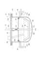
- the pyrolysis reactor 21 includes a cylindrical intermediate portion 21a with an open top, and a bottom portion having a bottom curved surface 21c that continues from the lower end 21b of the intermediate portion 21a and has a convex center downward. 21d, and a lid part 25 that covers the upper part of this intermediate part 21a.
- the generation of residue is suppressed by the shape of the pyrolysis reactor 21 and the stirring device 23, which will be described later. Further, the bottom portion 21d is not provided with an outlet for discharging residue and the like.
- the efficiency of heat conduction from the bottom 21d to the workpiece M is improved.
- the opening at the top of the intermediate portion 21a serves as an outlet 21f for taking out the processed material (residue etc.) after thermal decomposition.
- the lid part 25 can be opened and closed with respect to the opening 21f of the intermediate part 21a via an elevating mechanism 29, and maintenance of the pyrolysis reactor 21 can be easily performed by opening the lid part 25.
- This lid part 25 communicates with an input port 25a into which the material to be processed M is input, and a discharge part 24 which discharges (supplies) the pyrolysis gas G1 generated inside the pot toward the first condenser 3 (outside).
- a discharge port 24x is provided.
- a detachable connection part 24a is provided between the discharge part 24 and the first gas pipe 6a connected to the first condensing part 31 of the first condenser 3.
- the lid portion 25 is provided with a stirring device 23 to be described later, a thermocouple 25b for measuring the temperature inside the pot, and an inlet 25z for introducing an inert gas such as nitrogen into the pot. Note that it is also possible to open the lid portion 25 and introduce the processing material M through the opening 21f.
- Heating furnace 22 As shown in FIGS. 1 and 2, the heating furnace 22 is provided so as to surround the pyrolysis reactor 21, and the pyrolysis reactor 21 is replaceably installed above it. Thereby, the pyrolysis reactor 21 can be removed from the heating furnace 22 and the residue can be processed, and the residue can be easily recovered and the workability is good. Further, the heating furnace 22 has a combustion device 5, which will be described later, and heats the bottom 21d of the pyrolysis reactor 21 and at least the lower part 21b of the intermediate part 21a.
- An exhaust port 22a is provided on the upper side surface of the heating furnace 22 as an exhaust heat supply section for discharging (supplying) exhaust gas in the furnace to a heat insulating member 33 and an exterior member 34, which will be described later.
- a first exhaust pipe 7a is connected to this exhaust port 22a, and is communicated with an exhaust tower 22b via a valve.
- the stirring device 23 has a driving portion 23b provided on the lid portion 25 of the pyrolysis reactor 21, and a shaft portion 27 that rotates approximately at the center of the pyrolysis reactor 21, and a shaft portion 23b. It has a blade part 26 attached to the lower part of the part 27 and a shaft holding part 28.
- the shaft part 27 extends from the lower shaft part 27a to which the blade part 26 is attached and the drive part 23b of the stirring device 23, and can be inserted and fitted into the lower shaft part 27a and connected to the drive part 23b. It is divided into an upper shaft portion 27b.
- the shaft holding portion 28 rotatably holds the lower shaft portion 27a in the intermediate portion 21a. Thereby, the blade portion 26 rotates stably without eccentricity, and it is possible to prevent the processed material M from sticking to the inside of the pot.
- the blade portion 26 includes a lower edge portion 26a that is curved along the bottom curved surface 21c of the bottom portion 21d of the pyrolysis reactor 21, and a lower edge portion 26a that extends from both sides of the lower edge portion 26a of the pyrolysis reactor 21. It has a pair of rising portions 26b rising along the annular surface 21e of the intermediate portion 21a. The lower edge portion 26a of the blade portion 26 and the lower end of the rising portion 26b are opposed to the bottom curved surface 21c of the bottom portion 21d and the annular surface 21e of the lower end 21b of the intermediate portion 21a.
- the blades 26 are shaped like the bottom curved surface 21c and the annular shape. It is brought into sliding contact with the surface 21e.
- the processed material M can be stripped off or removed while it is still small so that it does not stick to the bottom 21d (bottom curved surface 21c) and annular surface 21e of the pyrolysis vessel 21, thereby reducing the efficiency of pyrolysis. It can be suppressed.
- the blade portion 26 is a plate-like member 26c that is thinner than the diameter of the shaft portion 27 including the lower shaft portion 27a, which will be described later.
- the plate member 26c has a plane 26d that is parallel to the axial direction of the shaft portion 27 and perpendicular to the bottom curved surface 21c and the annular surface 21e of the bottom portion 21d.
- the upper edge 26e of the blade portion 26 has a linear portion 26e1 perpendicular to the shaft portion 23a, and an inclined portion 26e2 connecting the upper end 26b1 of the rising portion 26b and the linear portion 26e1. and has.
- a thermocouple 25b is arranged near the center side (lower shaft portion 27a) inside the furnace. This shape of the blade portion 26 allows accurate temperature measurement by avoiding contact with the thermocouple 25b. Moreover, since the material M near the side surface 21e can be guided (stirred) toward the center of the furnace (lower shaft portion 27a), the efficiency of thermal decomposition is not reduced.
- the blade portion 26 has a protrusion 26f that stands perpendicularly to the plane 26d of the plate-like member 26c.
- This protruding portion 26f is perpendicular to the shaft portion 27 including the lower shaft portion 27a, and scrapes and stirs the material M to be processed.
- the blade portion 26 includes a lower shaft portion 27a that can be connected to an upper shaft portion 27b, and a shaft holding portion 28 that rotatably holds the lower shaft portion 27a in the intermediate portion 21a of the pyrolysis reactor 21.
- This shaft holding portion 28 is composed of, for example, a frame extending in all directions from the center of the pot, and the end portion of the frame is fixed to the annular surface 21e of the pyrolysis pot 21.
- a connecting portion 27c that connects to the upper shaft portion 27b is formed at the tip of the lower shaft portion 27a, and a blade portion 26 is provided at the lower portion.
- the pyrolysis reactor 21 can be used interchangeably. For example, by connecting the removed pyrolysis furnace 21 to another motor or the like, processing of the residue and maintenance become easy.
- the oil conversion method (processing) for thermally decomposing the processed material M using the above-mentioned oil conversion apparatus 1 pyrolysis furnace 2 will be described in more detail.
- the workpiece M is filled (injected) into the pot up to the workpiece filling line F1.
- the material M As the material M is heated, it liquefies and boils (expands), and the liquid level reaches the boiling liquid level F2, which is the expansion line of the material.
- the discharge port 24x of the discharge section 24 is provided in the lid section 25 above the boiling liquid level F2. Therefore, the input amount of the processed material M is adjusted to be below the processed material filling line F1 so that the processed material M does not reach the boiling liquid level F2 when it is liquefied. Further, by placing the processing material filling line F1 below the above-mentioned shaft holding portion 28, the influence on stirring of the processing material M can also be suppressed.
- oil is added together with the material to be treated M. Since the treated material M is solid, by adding oil, the state of heat transfer with the inner surface (inner wall) of the pyrolysis reactor 21 is improved, and the pyrolysis can proceed efficiently.
- the oil used is, for example, waste oil collected during the flow process of the first and second gas pipes 6c1 and 6c2 and the off-gas pipe 6c. Alternatively, it may be an amount equivalent to heavy oil recovered by the first and second condensers 3 and 4, light oil, or kerosene. However, those with a high water content are not preferred because they require drainage.
- nitrogen is introduced from the inlet 25z of the pyrolysis reactor 21 to make the interior of the pyrolysis reactor 21 and the discharge part 24 anoxic. If oxygen exists inside during thermal decomposition, it combines with the carbon of the heated material M to generate carbon dioxide, so the generation of carbon dioxide is suppressed due to the anoxic state.
- the outer surface of the pyrolysis pot 21 is heated, and the material to be treated M begins to melt from the inner surface of the pot, and liquid is generated on the inner surface of the pot in the bottom portion 21d and the intermediate portion 21a.
- a viscous liquid (semi-solid) is generated inside, and pyrolysis gas G1 is generated in a portion. Then, when the amount of semi-solid increases, the rotation of the shaft section 27 is started, and the stirring by the blade section 26 is started.
- the liquid level of the liquefied processing material M reaches the boiling liquid level F2, which becomes the processing material expansion line. Since the discharge port 24x of the discharge portion 24 is provided in the lid portion 25 above the boiling liquid level F2, the liquefied processed material M does not overflow to the discharge port 24x and flow into the first condenser 3 side. Therefore, only the pyrolysis gas G1 can be supplied (discharged) to the first condenser 3 side, and the purity of the oil can be maintained at a high level.
- the heating (flame) of the heating furnace 22 extends throughout the interior of the heating furnace 22, but since the intermediate portion 21a near the opening of the heating furnace 22 is close to the outside air, the inner wall of the pot in that portion is difficult to be heated.
- stirring is insufficient near the lower end 21b that is in contact with the bottom 21d below the line L1, sticking (burning) of the processed material M is likely to occur on the inner wall of the furnace, and this line L1 becomes the upper limit line for sticking formation. As shown in FIG.
- the sliding contact line L2 of the blade portion 26 that slides on the bottom curved surface 21c of the bottom portion 21d and the annular surface 21e of the intermediate portion 21a is located above the sticking generation upper limit line L1, so that the processing material M is It does not stick to the inner surface of the pot, and even if it does stick, the blades 26 can remove the stuck object within a small amount, and thermal decomposition can be carried out efficiently.
- the shape of the bottom portion 21d of the pyrolysis reactor 22 will be described in detail with reference to FIGS. 8 and 9.
- the line segment 21x is curved (in a downwardly convex arc shape), and the bottom portion of the line segment 21x has a bottom curved surface 21c formed by a rotating body.
- 21d has a hemispherical shape or a similar dome shape with the center convex downward (vertically downward), and the bottom surface 21c is a curved surface.
- the line segment is not limited to a curved line, and may be a straight line segment 21y as shown in FIG. In this case, the bottom portion 21d having the bottom surface 21c formed by the rotating body of the straight line segment 21y has a conical shape with the center convex downward (vertically downward).
- the bottom portion has a downwardly convex peripheral portion and a concave portion in the center.
- the liquefied processed material 101 is filled around the periphery.
- the downwardly directed concave portion (the upwardly protruding portion) in the center of the bottom is the part that is most likely to be heated, the processed material M is likely to be scorched in this central portion.
- the first condenser 3 generally includes a first condensing section 31 that condenses the pyrolysis gas G1, and a liquefied (oiled) hydrocarbon oil condensed in the first condensing section 31.
- a first storage tank 32 for storage is provided.
- the first gas pipe 6a connected to the upper part of the first condensing part 31 is provided with a heat retaining member 33 that covers the periphery thereof.
- the first storage tank 32 is covered with an exterior member 34 around the first storage tank 32 .
- cooling water C1 is supplied (circulated) to the first condensing section 31 from a cooling water tank 37.
- an outlet 32a is provided to take out (discharge) the liquefied (oiled) hydrocarbon oil.
- a first exhaust pipe 7a connected to the exhaust port 22a of the heating furnace 22 is connected to the lower part of the heat retaining member 33 via a switching valve (not shown).
- a second exhaust pipe 7b is connected to the upper part of the heat retaining member 33, which supplies the exhaust gas H2 flowing through the heat retaining member 33 to the exterior member 34.
- a second exhaust pipe 7b is connected to the lower part of the exterior member 34, and a third exhaust pipe 7c is connected to the upper part of the exterior member 34 for discharging the exhaust gas H3 flowing inside the exterior member 34 to the outside. ing.
- the third exhaust pipe 7c is connected to the exhaust tower 22b.
- the exhaust heat H1 from the heating furnace 22 is supplied (exhaust heat gas H2, H3) into the heat insulating member 33 and the exterior member 34, so the first storage tank 32 and the first gas pipe 6a are heated from the outside. It is heated by exhaust gas from the furnace 21. Therefore, the exhaust heat gas can be effectively utilized, improving the operating efficiency of the entire oil conversion equipment and contributing to energy savings.
- a heater 35 that heats the inside of the first storage tank 32 is attached to the exterior member 34.
- the first storage tank 32 is heated to a temperature of 150° C. by the heater 35, and light oil having a flash point of 20° C. or lower is separated so that it can be recovered by the second condenser 4.
- the gas G2 generated in the first condenser 3 is supplied to the second condenser 4 via the second gas pipe 6b above the first storage tank 32.
- the second condenser 4 generally includes a second condensing section 41 that condenses the gas G2, and stores the liquefied (oiled) light hydrocarbon oil condensed in the second condensing section 41.
- a second storage tank 42 is provided.
- cooling water C2 is supplied (circulated) to the second condensing section 41 from a cooling water tank 47.
- an outlet 42a is provided to take out (discharge) the liquefied (oiled) light hydrocarbon oil.
- the cooling water tank 37 of the first condenser 3 and the cooling water tank 47 of the second condenser 4 are separate systems, and each is independently controlled. Further, the cooling water C2 in the cooling water tank 47 is cooled and reused by a radiator or the like (not shown). By cooling the cooling water on the downstream side, the off-gas G3 is prevented from containing excess oil and the like.
- the length L2 of the second condensing section 41 is longer than the length L1 of the first condensing section 31, for example, twice or more. This improves the oil conversion rate in the second condenser 4 and prevents oil mist from flowing (circulating) into the offgas G3. As will be described later, in the present invention, since the off-gas G3 is reused in the heating furnace 22, impurities in the off-gas G3 are reduced by increasing the length L2 of the second condensing section 41.
- the off-gas G3 that has passed (generated) without being condensed in the second condenser 4 is transferred from the upper part of the second storage tank 42 to the combustion device (deodorizing device) 5 via the third gas pipe (off-gas pipe) 6c. It is guided (supplied) as combustion fuel to As a result, the exhaust heat gas of the heating furnace 21 can be used more effectively, and the operating efficiency of the entire oil converting device is improved.As shown in FIGS. It has a burner section 51 that performs combustion. As described above, the first exhaust pipe 7a is connected to the heating furnace 22, and the exhaust gas from the heating furnace 22 is passed through the second exhaust pipe 7b and the third exhaust pipe 7c to the heat insulating member 33 and the exterior. It is supplied to member 34. In this way, the off-gas G3 is not released into the atmosphere, but is subjected to high-temperature treatment (combustion) to be deodorized and reused, resulting in good energy efficiency.
- the combustion device 5 includes an air supply machine 52 that supplies combustion air for the combustion device 5, and an air pipe 52a of the air supply machine 52 is connected to the combustion device 5 through a venturi 53. has been done. Furthermore, the combustion pipe 6c5 of the above-mentioned off-gas pipe 6c is connected to the venturi 53. When combustion air is supplied from the air supply device 52 toward the venturi 53, the inside of the venturi 53 becomes a negative pressure, and off-gas G3 is sucked from the combustion pipe 6c5.
- the amount of off-gas G3 supplied can be adjusted by the amount of air supplied by the air supply device 52, so the off-gas G3 can be effectively utilized. Then, a mixture of combustion air and off-gas G3 is supplied to the burner section 51 and ignited by the plug 54.
- the off-gas piping 6c is generally connected to a discharge pipe 6c1 provided at the upper part of the second storage tank 42, and discharges oil collected in the discharge pipe 6c1 to the outside. It has an exhaust pipe 6c2, and a gradient pipe 6c3 that communicates with the outlet pipe 6c1 and is provided near the combustion device 5 and connected to the trap chamber 6x that reduces the flow velocity of the off-gas G3.
- the gradient pipe 6c3 has a gradient that increases from the second storage tank 42 (condenser) side toward the combustion device 5 side, and the part of the off-gas pipe 6c where the discharge pipe 6c2 is provided is the lowest position. There is.
- the off-gas G3 is cooled while flowing through the off-gas pipe 6c, and the oil contained therein is liquefied.
- the oil produced in the pipe can be guided and recovered to the discharge pipe 6c2 provided with the lower valve 6y. It is possible to collect excess oil and remove impurities as fuel, and also prevent staining and clogging of pipes, etc.
- the trap chamber 6x has an internal space that expands along a direction perpendicular to or intersecting the inflow direction from the gradient pipe 6c3, and a branch pipe 6c4 is provided along the inflow direction of the gradient pipe 6c3.
- the off-gas G3 released into the internal space from the gradient pipe 6c3 collides with the wall of the internal space, and the oil contained therein adheres to the wall during the collision. Thereby, oil can be further removed from the off-gas G3, the flame of the combustion device 5 can be stably maintained, and thermal decomposition can also be stabilized.
- the branch pipe 6c4 includes a first valve 6d1 that adjusts the gas supply to the combustion pipe 6c5 connected to the venturi 53, and a first valve 6d1 that adjusts the gas supply to the power generation pipe 6c6 connected to the power generation unit 40.
- a second valve 6d2 is provided.
- the power generation unit 40 includes, for example, a hydrogenation device 41 and a power generation device 42 such as a fuel cell, and can control the amount of power generation by adjusting the gas supply with the second valve 6d2.
- the pyrolysis gas G1 generated in the pyrolysis reactor 21 was supplied to the first gas pipe 6a connected to the upper part of the first condensation part 31 via the discharge part 24 that discharges to the outside of the reactor.
- a water trap 60 illustrated in FIGS. 12 and 13 may be interposed in the middle of the discharge section 24 (between the pyrolysis tank 21 and the first condenser 3).
- This water trap 60 roughly includes an introduction pipe 62 that introduces the pyrolysis gas G1, and an outlet pipe 63 that leads out the pyrolysis gas G1 that has passed through the water trap 60, which will be described later, to the first condenser 31 (condenser). It has a water contact part 64 that brings water W into contact with pyrolysis gas G1.
- the water trap 60 includes a main body 61 having a storage section 61a for storing water W, and an inlet pipe 62 and an outlet pipe 63 are attached to the upper part of the main body 61.
- the inlet pipe 62 supplies the pyrolysis gas G1 to the water contact part 64
- the outlet pipe 63 supplies the pyrolysis gas G1 that has passed through the water contact part 64 to the outside of the main body 61 of the water trap 60 (the first condensing part 31).
- the water trap 60 of the first embodiment illustrated in FIG. 12 the water trap 60 includes a shower as a jet supply section 66 that supplies a jet of water WS to the water contact section 64. This shower 66 is supplied with water W stored in a storage section 61a, which is pumped up by a pump 67.
- the water contact portion 64 includes a bottom portion 65a that receives water W, and an upper opening 65g as an open portion for supplying water from the shower 66 toward the bottom portion 65a in the form of a jet WS.
- a gas supply tool 65 including a side portion 65b and a rear portion 65c as a side wall portion surrounding the upper opening 65g so that the pyrolysis gas G1 does not pass therethrough.
- An upper introduction port 65d of the gas supply device 65 communicates with the introduction pipe 62, and a pair of side portions 65b are provided facing each other with the bottom portion 65a in between. Further, a rear portion 65c is provided from the inlet 65d toward the bottom portion 65a between the pair of side portions 65b, 65b. Therefore, the pyrolysis gas G1 supplied from the inlet 65d heads toward the upper opening 65g without being diffused by these side walls 65b and 65c. Further, the lower end of the rear portion 65c does not contact the bottom portion 65a, and a rear slit 65e is formed. Then, the pyrolysis gas G1 supplied to the upper opening 65g comes into contact with the jet stream WS supplied from the shower 66. Since the pyrolysis gas G1 is brought into contact with the jet stream WS at the upper opening 65g (water contact portion 64), there is no clogging of the introduction pipe 62, and stable operation can be achieved.
- the processed material M contains PET (polyethylene terephthalate), it will be gasified by thermal decomposition at about 300° C. and contained in the thermal decomposition gas G1.
- PET polyethylene terephthalate
- the Cl chlorine
- PVC polyvinyl chloride
- the pyrolysis gas G1 is cooled by 50°C or more, so that the PET component is crystallized and can be recovered together with the water W.
- PET has a high specific gravity, it precipitates in the lower part of the storage section 61a. Therefore, in the piping upstream of the first condenser 3 (downstream of the water trap 60), clogging due to crystallization of the PET component can be suppressed, and the recovery efficiency of heavy oil and the like can also be improved.
- Cl (chlorine content) of PVC (polyvinyl chloride) is easily dissolved in water, it can also be recovered by dissolving it in water W using the water trap 60.
- the water trap 60 in the middle of the discharge part 24, these components can be removed on the upstream side of the first condenser 3. It can be suitably used for chemical recycling of substance M. Although it is preferable to heat-treat the PET bottles, labels, and caps separately in terms of chemical recycling efficiency and the purity of extracted oil, by providing the water trap 60, it is possible to heat-treat them without separating them. be.
- the water W1 that has come into contact with the jet stream WS at the upper opening 65g flows down from the front edge 65f of the bottom portion 65a on the upper opening 65g side to the storage portion 61a.
- the remaining water W2 that came into contact from the rear slit 65e flows down to the storage section 61a.
- the water W stored in the storage portion 61a is pumped up by the pump 67 and supplied again as the jet stream WS from the shower 66, and is repeatedly used. Note that it is preferable to provide a meter for measuring pH, chlorine concentration, etc. in the supply process (piping) to the shower 66, monitor the measurement, and collect and replace the water W manually or automatically.
- the above-mentioned gas supply device 65 is omitted, and the introduction pipe 62 is extended to the spout 68 located in the water W stored in the storage section 61a for thermal decomposition.
- a water contacting portion 64 is configured by supplying gas G1 and ejecting it from an ejection port 68.
- the spout 68 is, for example, a plurality of through holes bored in the introduction pipe 62.
- the pyrolysis gas G1 spouted from the spout 68 is cooled in the water W in the storage section 61a, the PET component is crystallized, and the Cl (chlorine content) of PVC (polyvinyl chloride) is removed from the water W. can be dissolved and recovered.
- the pyrolysis gas G1 that has passed through the storage section 61a (water contact section 64) is led out to the outside from the outlet 63a of the outlet pipe 63 located above the water surface of the storage section 61a.
- a removal tool 69 is provided near the spout 68 of the outlet pipe 63.
- This removal tool 69 is composed of an annular portion 69a and a removal portion 69b such as a brush, and can be moved by sliding the removal portion 69b around the spout 68 along the tube axis direction of the outlet tube 63 via the annular portion 69a. , to prevent clogging by removing PET components that adhere to the jet nozzle 68.
- the water W is pumped up by the pump 67, supplied to the storage section 61a, and reused.
- PET polyethylene terephthalate
- the introduction pipe 62 is heated from the outside with the exhaust heat gas H1 of the heating furnace 22.
- the introduction pipe 62 is covered with a heat retaining member 33, and exhaust heat gas H1 of the heating furnace 22 is supplied into the heat retaining member 33 from the exhaust port (exhaust heat supply section) 22a of the heating furnace 22 via the first exhaust pipe 7a.
- exhaust heat gas H1 of the heating furnace 22 is supplied into the heat retaining member 33 from the exhaust port (exhaust heat supply section) 22a of the heating furnace 22 via the first exhaust pipe 7a.
- the heat retaining member 33 is connected to a second exhaust pipe 7b that discharges the exhaust gas flowing through the inside thereof to the outside.
- the second exhaust pipe 7b is connected to the exhaust tower 22b via a third exhaust pipe 7c, and a valve 7x is provided in the middle.
- a bypass path 70 which will be described later, by closing this valve 7x, the entire amount of exhaust gas H1 from the heating furnace 22 can be supplied to the interior of the exterior member 34 via the fourth exhaust pipe 7d, resulting in energy saving. contributes to
- a switchable bypass path 70 may be provided between the inlet pipe 62 and the outlet pipe 63 so as to bypass the water trap 60.
- an inlet-side three-way valve 71 is provided in the inlet pipe 62
- an outlet-side three-way valve 72 is provided in the outlet pipe 63, and these three-way valves 71 and 72 are connected by a horizontal pipe 73 to enable switching.
- a horizontal pipe 73 instead of the horizontal pipe 73, a slope 70a that descends toward the pyrolysis reactor 21 may be provided.
- the water trap 60 of each of the above embodiments can be applied not only to the batch type pyrolysis reactor 21 as in the above embodiment, but also to a continuous type pyrolysis apparatus.
- a continuous type pyrolysis furnace shown in Patent Document 4 it is possible to connect a water trap 60 as a PET removal device to the pyrolysis gas discharge duct 6, and it is possible to implement an oil conversion device combining these. Can be done.
- the discharge part 24 that communicates with the discharge port 24x of the lid part 25 is provided with a connecting part 24a that is detachable from the first gas pipe 6a that connects to the first condensing part 31.
- the configuration of the connecting part is not limited to that of the embodiment described above.
- the discharge part 24 shown in FIG. 16 has an elbow 24e that connects the discharge port 24x with a connecting part 24b located outside the movement trajectory 25' of the lid part 25 when the lid part 25 is opened and closed.
- a hinge 24y is provided at the upper portion where the elbow 24e and the connecting portion 24b are continuous.
- the elbow 24e can swing to the upper part of the connecting part 24b by the hinge 24y and move (evacuate) out of the movement trajectory 25' of the lid part 25 (reference numeral 24e).
- the first condenser 3 and the second condenser 4 are also configured as two condensers that condense the pyrolysis gas generated in the pyrolysis furnace.
- the number of condensers is not limited to two, and may be one or three or more.
- the water trap 60 described above is provided on the upstream side of the condenser (first condenser), and the off-gas pipe 6c is provided on the most downstream condenser, similar to the above embodiment.
- the lower edge part 26a and the rising part 26b of the blade part 26 are formed of the plate-like member 26c which is linear in plan view, but the structure is not limited to this, and for example, a structure as shown in FIG. 17 may be used. good.
- FIGS. 17(a) and 17(b) only the rising portion 26b of the blade portion 26 is spirally shaped with respect to the central axis CA (arranged at the position of the shaft member 27) which is the forming axis of the annular surface 21e.
- both the rising portion 26b and the lower edge portion 26a of the blade portion 26 are spiral-shaped.
- the processed material that has passed through the bottom surface 21c is more firmly collected in the direction of arrow R2, which is the direction closer to the central axis CA, and the overall stirring is performed more rationally.
- the rotation of the blade portion 21 around the central axis CA is reversed, the directions R1 to R3 will be reversed, and clumping of the material to be processed can be alleviated.
- the present invention can be used, for example, as an oil conversion device for chemically recycling waste plastics and waste tires, and as an oil conversion method using the same. Further, the present invention enables chemical recycling of composite materials such as LIMEX (registered trademark) containing 50% or more of inorganic substances such as calcium carbonate.
- LIMEX registered trademark
Landscapes
- Chemical & Material Sciences (AREA)
- Engineering & Computer Science (AREA)
- Oil, Petroleum & Natural Gas (AREA)
- Organic Chemistry (AREA)
- Materials Engineering (AREA)
- Life Sciences & Earth Sciences (AREA)
- Chemical Kinetics & Catalysis (AREA)
- General Chemical & Material Sciences (AREA)
- Wood Science & Technology (AREA)
- General Engineering & Computer Science (AREA)
- Mechanical Engineering (AREA)
- Combustion & Propulsion (AREA)
- Environmental & Geological Engineering (AREA)
- Physics & Mathematics (AREA)
- Polymers & Plastics (AREA)
- Medicinal Chemistry (AREA)
- Thermal Sciences (AREA)
- Health & Medical Sciences (AREA)
- Sustainable Development (AREA)
- Production Of Liquid Hydrocarbon Mixture For Refining Petroleum (AREA)
- Separation, Recovery Or Treatment Of Waste Materials Containing Plastics (AREA)
- Vertical, Hearth, Or Arc Furnaces (AREA)
- Waste-Gas Treatment And Other Accessory Devices For Furnaces (AREA)
Priority Applications (2)
| Application Number | Priority Date | Filing Date | Title |
|---|---|---|---|
| JP2024530582A JP7566396B2 (ja) | 2022-08-19 | 2023-08-18 | 油化装置及びこれを用いた油化方法 |
| US19/104,484 US20260062618A1 (en) | 2022-08-19 | 2023-08-18 | OIL-LIQUEFACTION APPARATUS, AND OlL-LIQUEFACTION METHOD USING SAME |
Applications Claiming Priority (2)
| Application Number | Priority Date | Filing Date | Title |
|---|---|---|---|
| JP2022-130997 | 2022-08-19 | ||
| JP2022130997 | 2022-08-19 |
Publications (1)
| Publication Number | Publication Date |
|---|---|
| WO2024038916A1 true WO2024038916A1 (ja) | 2024-02-22 |
Family
ID=89941892
Family Applications (1)
| Application Number | Title | Priority Date | Filing Date |
|---|---|---|---|
| PCT/JP2023/029905 Ceased WO2024038916A1 (ja) | 2022-08-19 | 2023-08-18 | 油化装置及びこれを用いた油化方法 |
Country Status (3)
| Country | Link |
|---|---|
| US (1) | US20260062618A1 (https=) |
| JP (1) | JP7566396B2 (https=) |
| WO (1) | WO2024038916A1 (https=) |
Citations (6)
| Publication number | Priority date | Publication date | Assignee | Title |
|---|---|---|---|---|
| JPH0450293A (ja) * | 1990-06-16 | 1992-02-19 | U S S:Kk | 合成樹脂用の油化装置 |
| JPH09316459A (ja) * | 1996-05-31 | 1997-12-09 | Hitachi Zosen Corp | 廃プラスチックの熱分解油化システム |
| JPH10273677A (ja) * | 1997-03-31 | 1998-10-13 | Hitachi Zosen Corp | 廃プラスチック油化生成物の凝固点降下装置 |
| JP2001316517A (ja) * | 2000-05-02 | 2001-11-16 | Ishikawajima Harima Heavy Ind Co Ltd | 廃プラスチック処理方法および装置 |
| JP2012011299A (ja) * | 2010-06-30 | 2012-01-19 | Altis:Kk | 熱分解装置、脱塩素処理装置、熱分解方法および脱塩素方法 |
| JP2019203124A (ja) * | 2018-05-18 | 2019-11-28 | 公立大学法人北九州市立大学 | 熱分解油の製造方法 |
Family Cites Families (1)
| Publication number | Priority date | Publication date | Assignee | Title |
|---|---|---|---|---|
| JP3484585B2 (ja) * | 1994-10-12 | 2004-01-06 | 日立造船株式会社 | プラスチック熱分解釜におけるコーキング層形成防止装置 |
-
2023
- 2023-08-18 US US19/104,484 patent/US20260062618A1/en active Pending
- 2023-08-18 WO PCT/JP2023/029905 patent/WO2024038916A1/ja not_active Ceased
- 2023-08-18 JP JP2024530582A patent/JP7566396B2/ja active Active
Patent Citations (6)
| Publication number | Priority date | Publication date | Assignee | Title |
|---|---|---|---|---|
| JPH0450293A (ja) * | 1990-06-16 | 1992-02-19 | U S S:Kk | 合成樹脂用の油化装置 |
| JPH09316459A (ja) * | 1996-05-31 | 1997-12-09 | Hitachi Zosen Corp | 廃プラスチックの熱分解油化システム |
| JPH10273677A (ja) * | 1997-03-31 | 1998-10-13 | Hitachi Zosen Corp | 廃プラスチック油化生成物の凝固点降下装置 |
| JP2001316517A (ja) * | 2000-05-02 | 2001-11-16 | Ishikawajima Harima Heavy Ind Co Ltd | 廃プラスチック処理方法および装置 |
| JP2012011299A (ja) * | 2010-06-30 | 2012-01-19 | Altis:Kk | 熱分解装置、脱塩素処理装置、熱分解方法および脱塩素方法 |
| JP2019203124A (ja) * | 2018-05-18 | 2019-11-28 | 公立大学法人北九州市立大学 | 熱分解油の製造方法 |
Also Published As
| Publication number | Publication date |
|---|---|
| JPWO2024038916A1 (https=) | 2024-02-22 |
| JP7566396B2 (ja) | 2024-10-15 |
| US20260062618A1 (en) | 2026-03-05 |
Similar Documents
| Publication | Publication Date | Title |
|---|---|---|
| JP3836112B2 (ja) | 廃棄プラスチックの油化設備 | |
| DK2831198T3 (en) | Device and method for catalytic depolymerization of hydrocarbon-containing material | |
| MXPA04002431A (es) | Aceite diesel de residuos mediante despolimerizacion catalitica con introduccion de energia mediante un sistema de bomba-agitador. | |
| EP4274872A1 (en) | Systems and apparatus for pyrolysis of end of life plastic | |
| KR20240134927A (ko) | 플라스틱 열분해 반응기 | |
| JP5678400B2 (ja) | 流動槽、流動槽からの固体粒子の排出方法および被処理物の処理方法 | |
| WO2024038916A1 (ja) | 油化装置及びこれを用いた油化方法 | |
| US20250314427A1 (en) | Furnace, fluid feed component, fluid reforming system and method of reforming a fluid | |
| JP2004035851A (ja) | 油化装置 | |
| WO2022118738A1 (ja) | 廃プラスチック油化装置および油化方法 | |
| JPH1190387A (ja) | 廃プラスチックの脱塩素方法および脱塩素装置 | |
| CN105778970A (zh) | 一种连续进料、排渣废旧有机物裂解再生利用的安全环保炼油工艺 | |
| CN105505426B (zh) | 废塑料熔盐裂解塔 | |
| US7204928B2 (en) | Process and apparatus for the fractional distillation of crude oil | |
| JPWO2024038916A5 (https=) | ||
| JP2009270052A (ja) | 小型廃プラスチック油化装置 | |
| RU2348470C1 (ru) | Способ и установка для получения битума из устаревших кровельных материалов | |
| JP2002180068A (ja) | 廃プラスチックの油化装置 | |
| JP7132474B2 (ja) | 廃プラスチック熱分解方法及び廃プラスチック熱分解装置並びに廃プラスチック油化システム | |
| US12203032B2 (en) | Apparatus for the treatment of plastics | |
| JP2007099850A (ja) | 廃プラスチックの油化方法およびその装置 | |
| JP4925745B2 (ja) | タール除去装置 | |
| JP2008013595A (ja) | 廃プラスチックの熱分解処理装置及び熱分解処理方法 | |
| JP4799072B2 (ja) | 熱分解油化装置 | |
| CA1113695A (en) | Apparatus for pyrolysis of hydrocarbon starting products |
Legal Events
| Date | Code | Title | Description |
|---|---|---|---|
| 121 | Ep: the epo has been informed by wipo that ep was designated in this application |
Ref document number: 23853688 Country of ref document: EP Kind code of ref document: A1 |
|
| ENP | Entry into the national phase |
Ref document number: 2024530582 Country of ref document: JP Kind code of ref document: A |
|
| WWE | Wipo information: entry into national phase |
Ref document number: 2501000972 Country of ref document: TH |
|
| NENP | Non-entry into the national phase |
Ref country code: DE |
|
| 122 | Ep: pct application non-entry in european phase |
Ref document number: 23853688 Country of ref document: EP Kind code of ref document: A1 |