WO2024038894A1 - 光学素子 - Google Patents
光学素子 Download PDFInfo
- Publication number
- WO2024038894A1 WO2024038894A1 PCT/JP2023/029708 JP2023029708W WO2024038894A1 WO 2024038894 A1 WO2024038894 A1 WO 2024038894A1 JP 2023029708 W JP2023029708 W JP 2023029708W WO 2024038894 A1 WO2024038894 A1 WO 2024038894A1
- Authority
- WO
- WIPO (PCT)
- Prior art keywords
- liquid crystal
- light
- optically anisotropic
- diffraction element
- anisotropic layer
- Prior art date
- Legal status (The legal status is an assumption and is not a legal conclusion. Google has not performed a legal analysis and makes no representation as to the accuracy of the status listed.)
- Ceased
Links
Images




Classifications
-
- G—PHYSICS
- G02—OPTICS
- G02B—OPTICAL ELEMENTS, SYSTEMS OR APPARATUS
- G02B5/00—Optical elements other than lenses
- G02B5/18—Diffraction gratings
-
- G—PHYSICS
- G01—MEASURING; TESTING
- G01J—MEASUREMENT OF INTENSITY, VELOCITY, SPECTRAL CONTENT, POLARISATION, PHASE OR PULSE CHARACTERISTICS OF INFRARED, VISIBLE OR ULTRAVIOLET LIGHT; COLORIMETRY; RADIATION PYROMETRY
- G01J3/00—Spectrometry; Spectrophotometry; Monochromators; Measuring colours
- G01J3/12—Generating the spectrum; Monochromators
- G01J3/18—Generating the spectrum; Monochromators using diffraction elements, e.g. grating
-
- G—PHYSICS
- G01—MEASURING; TESTING
- G01J—MEASUREMENT OF INTENSITY, VELOCITY, SPECTRAL CONTENT, POLARISATION, PHASE OR PULSE CHARACTERISTICS OF INFRARED, VISIBLE OR ULTRAVIOLET LIGHT; COLORIMETRY; RADIATION PYROMETRY
- G01J3/00—Spectrometry; Spectrophotometry; Monochromators; Measuring colours
- G01J3/28—Investigating the spectrum
- G01J3/447—Polarisation spectrometry
-
- G—PHYSICS
- G02—OPTICS
- G02B—OPTICAL ELEMENTS, SYSTEMS OR APPARATUS
- G02B5/00—Optical elements other than lenses
-
- G—PHYSICS
- G02—OPTICS
- G02B—OPTICAL ELEMENTS, SYSTEMS OR APPARATUS
- G02B5/00—Optical elements other than lenses
- G02B5/04—Prisms
-
- G—PHYSICS
- G02—OPTICS
- G02B—OPTICAL ELEMENTS, SYSTEMS OR APPARATUS
- G02B5/00—Optical elements other than lenses
- G02B5/30—Polarising elements
Definitions
- the present invention relates to an optical element that spectrally separates incident light using a liquid crystal diffraction element.
- Liquid crystal diffraction elements that diffract and transmit incident light are known.
- a liquid crystal diffraction element a liquid crystal diffraction element having an optically anisotropic layer formed using a liquid crystal composition containing a liquid crystal compound is known.
- a liquid crystal diffractive element (optical element) is described with a local optical axis that varies along each interface between adjacent ones of the stacked birefringent sublayers such that the sublayers define respective lattice periods.
- the birefringent sublayer constituting the laminated birefringent sublayer is arranged so that the direction of the rod-shaped liquid crystal compound, that is, the direction of the optical axis derived from the liquid crystal compound, is , has an alignment pattern of liquid crystal compounds that rotates continuously in one direction.
- a liquid crystal diffraction element having an orientation pattern of a liquid crystal compound (liquid crystal orientation pattern) as described in Patent Document 1 can diffract (refract) incident light at an angle depending on the wavelength. Furthermore, if the light has the same wavelength, it can be diffracted at a certain angle.
- a liquid crystal diffraction element having a liquid crystal alignment pattern can be used for various purposes by utilizing such characteristics. For example, this liquid crystal diffraction element can be suitably used as a spectroscopic element in a hyperspectral camera that splits incident light into multiple wavelength ranges and takes pictures.
- Such a liquid crystal diffraction element can diffract and separate incident light.
- a liquid crystal diffraction element diffracts incident light so as to separate it into two different directions depending on the polarization. Therefore, devices such as hyperspectral cameras that use a liquid crystal diffraction element as a spectroscopic element have a problem in that it is difficult to utilize all of the separated light, that is, the utilization efficiency of the separated light is low.
- An object of the present invention is to solve the problems of the prior art, and to provide an optical element that uses a liquid crystal diffraction element to separate incident light and can improve the efficiency of using the separated light. There is a particular thing.
- the optical element of the present invention has the following configuration.
- the liquid crystal diffraction element includes an optically anisotropic layer having a liquid crystal alignment pattern in which the direction of an optical axis derived from a liquid crystal compound changes while continuously rotating along at least one in-plane direction,
- the liquid crystal diffraction element has at least two optically anisotropic layers in which a liquid crystal compound is twisted and oriented in a spiral shape along the thickness direction, and two of the optically anisotropic layers
- the utilization efficiency of the separated light can be improved in an optical element that uses a liquid crystal diffraction element to separate incident light.
- FIG. 1 is a diagram conceptually showing an example of the optical element of the present invention.
- FIG. 2 is a diagram conceptually showing an example of a liquid crystal diffraction element.
- FIG. 3 is a plan view of the optically anisotropic layer of the liquid crystal diffraction element shown in FIG. 2.
- FIG. 4 is a conceptual diagram showing the effect of the optically anisotropic layer of the liquid crystal diffraction element shown in FIG.
- FIG. 5 is a conceptual diagram showing the effect of the optically anisotropic layer of the liquid crystal diffraction element shown in FIG. 2.
- FIG. 6 is a diagram conceptually showing another example of a liquid crystal diffraction element.
- FIG. 1 is a diagram conceptually showing an example of the optical element of the present invention.
- FIG. 2 is a diagram conceptually showing an example of a liquid crystal diffraction element.
- FIG. 3 is a plan view of the optically anisotropic layer of the liquid crystal diffraction element shown in FIG
- FIG. 7 is a diagram conceptually showing an example of an exposure apparatus that exposes the alignment film of the liquid crystal diffraction element shown in FIG. 2.
- FIG. 8 is a diagram conceptually showing the operation of the liquid crystal diffraction element.
- FIG. 9 is a diagram conceptually showing an example of a spectroscopic element using the optical element of the present invention.
- FIG. 10 is a diagram conceptually showing another example of the optical element of the present invention.
- FIG. 11 is a diagram conceptually showing an example of a spectroscopic element using the optical element of the present invention.
- FIG. 12 is a diagram conceptually showing another example of the optical element of the present invention.
- FIG. 13 is a conceptual diagram for explaining an embodiment of the present invention.
- FIG. 14 is a conceptual diagram for explaining an embodiment of the present invention.
- a numerical range expressed using “ ⁇ ” means a range that includes the numerical values written before and after " ⁇ ” as lower and upper limits.
- (meth)acrylate is used to mean “one or both of acrylate and methacrylate.”
- “same” includes a generally accepted error range in the technical field.
- error ranges generally accepted in the technical field such as 99% or more, This shall include cases where it is 95% or more, or 90% or more.
- visible light refers to electromagnetic waves with wavelengths visible to the human eye, and refers to light in the wavelength range of 380 to 780 nm.
- Invisible light is light in a wavelength range of less than 380 nm and a wavelength range of more than 780 nm.
- light in the wavelength range of 420 to 490 nm is blue light
- light in the wavelength range of 495 to 570 nm is green light
- light in the wavelength range of 620 to 750 nm is blue light.
- the light in the area is red light.
- ultraviolet light is light in the wavelength range of less than 380 nm and 200 nm or more
- infrared light is light in the wavelength range of more than 780 nm. This is light in a wavelength range of 12,000 nm or less.
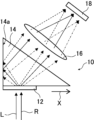
- FIG. 1 conceptually shows an example of the optical element of the present invention.
- the optical element 10 shown in FIG. 1 includes a liquid crystal diffraction element 12 and a prism 14.
- the liquid crystal diffraction element 12 has an optically anisotropic layer (numeral 26 in FIG. 2).
- the optically anisotropic layer has a liquid crystal alignment pattern in which the direction of an optical axis derived from a liquid crystal compound changes while continuously rotating along at least one in-plane direction.
- the optically anisotropic layer having such a liquid crystal alignment pattern that is, the liquid crystal diffraction element 12 having such an optically anisotropic layer, when unpolarized light is incident, spectrally spectra the incident light according to the wavelength.
- the right-handed circularly polarized light R right-handed circularly polarized light component R
- the left-handed circularly polarized light L left-handed circularly polarized light component L
- the liquid crystal diffraction element 12 diffracts the incident unpolarized light, separates the unpolarized light into right-handed circularly polarized light and left-handed circularly polarized light, and diffracts (refracts) the unpolarized light in the opposite direction.
- the liquid crystal diffraction element 12 is arranged on one surface of the prism 14.
- the surface on which this prism 14 is arranged is the first surface in the present invention.
- the liquid crystal diffraction element 12 diffracts right-handed circularly polarized light R toward the right in the figure and diffracts left-handed circularly polarized light L toward the left in the figure from among non-polarized incident light.
- the light diffracted to the left is reflected by the second surface 14a of the prism 14.
- the light diffracted in the right direction by the liquid crystal diffraction element 12 (left-handed circularly polarized light) and the light reflected by the second surface 14a of the prism 14 become parallel light and are emitted from the same surface of the prism 14 in the same direction. It is emitted. Note that the light reflected by the second surface 14a of the prism 14 is converted into left-handed circularly polarized light by reflection. Therefore, according to the present invention, the light separated by the liquid crystal diffraction element can be used with high utilization efficiency. The above points will be explained in detail later.
- FIG. 2 conceptually shows an example of a liquid crystal diffraction element.
- the illustrated liquid crystal diffraction element 12 includes a support 20, an alignment film 24, and an optically anisotropic layer 26.
- the optically anisotropic layer 26 is formed using a composition containing a liquid crystal compound 30.
- the optically anisotropic layer 26 has a predetermined liquid crystal alignment pattern in which the direction of the optical axis originating from the liquid crystal compound 30 changes continuously as it rotates along at least one direction.
- the liquid crystal diffraction element 12 has the support 20, the liquid crystal diffraction element does not need to have the support 20.
- the support body 20 may be peeled off from the structure shown in FIG. 2, and the liquid crystal diffraction element may be configured only with the alignment film 24 and the optically anisotropic layer 26.
- the support 20 and the alignment film 24 may be peeled off to form a liquid crystal diffraction element using only the optically anisotropic layer 26.
- the first surface of the prism 14, which will be described later, may act as a support.
- the liquid crystal diffraction element 12 has an optically anisotropic layer formed using a composition containing a liquid crystal compound, and the optically anisotropic layer has an optical axis derived from the liquid crystal compound.
- the liquid crystal alignment pattern has a liquid crystal alignment pattern in which the orientation of the liquid crystal changes while rotating continuously along at least one in-plane direction.
- the liquid crystal diffraction element 12 includes the support 20, the alignment film 24, and the optically anisotropic layer 26.
- the support body 20 supports the alignment film 24 and the optically anisotropic layer 26.
- the support 20 may be any of various sheet-like materials ( films, plates, layers) are available. Furthermore, the support may be flexible or non-flexible. Examples of the support include polyacrylic resin films such as polymethyl methacrylate, cellulose resin films such as cellulose triacetate, cycloolefin polymer films, resin films such as polyethylene terephthalate (PET), polycarbonate, and polyvinyl chloride; Additionally, a glass plate or the like can be used. Examples of the cycloolefin polymer film include "Arton” (trade name) manufactured by JSR Corporation and "Zeonor” (trade name) manufactured by Zeon Corporation.
- the thickness of the support 20 there is no limit to the thickness of the support 20, and the thickness that can hold the alignment film 24 and the optically anisotropic layer 26 can be determined as appropriate depending on the purpose of the liquid crystal diffraction element 12 and the material for forming the support 20. Just set it.
- Additives such as ultraviolet absorbers may be added to the support 20. It is preferable to add it to the support 20 as an ultraviolet absorber because it can improve the light resistance of the liquid crystal diffraction element 12.
- an alignment film 24 is formed on the surface of the support 20 .
- the alignment film 24 is an alignment film for aligning the liquid crystal compound 30 into a predetermined liquid crystal alignment pattern when forming the optically anisotropic layer 26 of the liquid crystal diffraction element 12.
- the optically anisotropic layer 26 has an optical axis 30A (see FIG. 3) originating from the liquid crystal compound 30 that is oriented along one in-plane direction (arrow X direction described later). It has a liquid crystal alignment pattern that changes as it rotates continuously. Therefore, the alignment film 24 of the liquid crystal diffraction element 12 is formed such that the optically anisotropic layer 26 can form this liquid crystal alignment pattern.
- the direction of the optical axis 30A is rotated is also simply referred to as "the optical axis 30A is rotated”.
- alignment films can be used as the alignment film 24.
- rubbed films made of organic compounds such as polymers, obliquely deposited films of inorganic compounds, films with microgrooves, and Langmuir films of organic compounds such as ⁇ -tricosanoic acid, dioctadecylmethylammonium chloride, and methyl stearate.
- Examples include a film in which LB (Langmuir-Blodgett) films are accumulated by the Blodgett method.
- the alignment film formed by rubbing treatment can be formed by rubbing the surface of the polymer layer several times in a certain direction with paper or cloth.
- Materials used for the alignment film include polyimide, polyvinyl alcohol, polymers having polymerizable groups described in JP-A-9-152509, JP-A-2005-97377, JP-A-2005-99228, and Preferred examples include materials used for forming alignment films and the like described in JP-A No. 2005-128503.
- a so-called photo-alignment film which is formed by irradiating a photo-alignable material with polarized or non-polarized light, is preferably used. That is, in the liquid crystal diffraction element 12, a photo-alignment film formed by applying a photo-alignment material on the support 20 is suitably used as the alignment film. Polarized light irradiation can be performed perpendicularly or obliquely to the photo-alignment film, and unpolarized light can be irradiated obliquely to the photo-alignment film.
- Examples of the photo-alignment material used in the photo-alignment film that can be used in the present invention include JP-A No. 2006-285197, JP-A No. 2007-76839, JP-A No. 2007-138138, and JP-A No. 2007-94071. Publication, JP 2007-121721, JP 2007-140465, JP 2007-156439, JP 2007-133184, JP 2009-109831, JP 3883848, and Patent No. Azo compounds described in JP-A No. 4151746, aromatic ester compounds described in JP-A No. 2002-229039, maleimides having photo-orientable units described in JP-A No. 2002-265541 and JP-A No.
- JP-A Preferable examples include photodimerizable compounds described in JP 2013-177561 and JP 2014-12823, particularly cinnamate compounds, chalcone compounds, and coumarin compounds.
- azo compounds, photocrosslinkable polyimides, photocrosslinkable polyamides, photocrosslinkable esters, cinnamate compounds, and chalcone compounds are preferably used.
- the thickness of the alignment film 24 is preferably 0.01 to 5 ⁇ m, more preferably 0.05 to 2 ⁇ m.
- the method for forming the alignment film there are no restrictions on the method for forming the alignment film, and various known methods can be used depending on the material for forming the alignment film.
- One example is a method in which an alignment film is applied to the surface of the support 20 and dried, and then the alignment film is exposed to laser light to form an alignment pattern.
- FIG. 7 conceptually shows an example of an exposure apparatus that exposes the alignment film 24 to form the above-mentioned alignment pattern.
- the exposure apparatus 60 shown in FIG. 7 includes a light source 64 including a laser 62, a beam splitter 68 that separates the laser beam M emitted by the laser 62 into two beams MA and MB, and two separated beams MA and MB. It includes mirrors 70A and 70B and ⁇ /4 plates 72A and 72B, which are respectively arranged on the optical path of the MB.
- the light source 64 emits linearly polarized light P 0 .
- the ⁇ /4 plate 72A converts linearly polarized light P 0 (ray MA) into right-handed circularly polarized light PR
- the ⁇ /4 plate 72B converts linearly polarized light P 0 (ray MB) into left-handed circularly polarized light PL .
- a support 20 having an alignment film 24 on which an alignment pattern has not yet been formed is placed in an exposure section, and two light beams MA and MB are made to intersect and interfere with each other on the alignment film 24, and the interference light is transmitted to the alignment film 24. irradiate and expose. Due to this interference, the polarization state of the light irradiated onto the alignment film 24 changes periodically in the form of interference fringes. As a result, an alignment pattern in which the alignment state periodically changes can be obtained in the alignment film 24. In the exposure device 60, the period of the alignment pattern can be adjusted by changing the intersection angle ⁇ of the two light beams MA and MB.
- the optical axis 30A derived from the liquid crystal compound 30 rotates in one direction.
- the length of one period in which the optical axis 30A rotates by 180 degrees can be adjusted.
- an optically anisotropic layer on an alignment film having an alignment pattern in which the alignment state changes periodically, the optical axis 30A originating from the liquid crystal compound 30 is oriented in one direction, as described later.
- An optically anisotropic layer 26 having a liquid crystal alignment pattern that rotates continuously can be formed. Further, by rotating the optical axes of the ⁇ /4 plates 72A and 72B by 90 degrees, the direction of rotation of the optical axis 30A can be reversed.
- the alignment film is provided as a preferred embodiment and is not an essential component.
- the optically anisotropic layer 26 and the like can be formed into the liquid crystal compound 30. It is also possible to configure a liquid crystal alignment pattern in which the direction of the originating optical axis 30A changes while continuously rotating along at least one in-plane direction.
- an optically anisotropic layer 26 is formed on the surface of the alignment film 24.
- the optically anisotropic layer 26 is composed of a liquid crystal compound 30 (liquid crystal compound molecules) on the surface of the alignment film. ) are shown.
- the optically anisotropic layer 26 has an oriented liquid crystal compound 30, similar to an optically anisotropic layer formed using a composition containing a normal liquid crystal compound. It has a stacked structure in the thickness direction.
- the optically anisotropic layer (liquid crystal layer) 26 is formed using a composition containing a liquid crystal compound.
- the optically anisotropic layer 26 functions as a general ⁇ /2 plate, that is, the mutually orthogonal light contained in the light incident on the optically anisotropic layer It has a function of giving a phase difference of half wavelength, that is, 180°, to two linearly polarized light components.
- the optically anisotropic layer 26 has a liquid crystal alignment pattern in which the direction of the optical axis 30A originating from the liquid crystal compound 30 changes while continuously rotating in one direction indicated by the arrow X in the plane.
- the optical axis 30A originating from the liquid crystal compound 30 is an axis in which the refractive index is the highest in the liquid crystal compound 30, that is, a so-called slow axis.
- the optical axis 30A is along the long axis direction of the rod shape.
- the optical axis 30A originating from the liquid crystal compound 30 is also referred to as “the optical axis 30A of the liquid crystal compound 30" or “the optical axis 30A.”
- the liquid crystal compounds 30 are two-dimensionally arranged in a plane parallel to the arrow X direction and the Y direction perpendicular to the arrow X direction. Note that in FIG. 2 and FIGS. 4 and 5, which will be described later, the Y direction is a direction perpendicular to the plane of the paper.
- FIG. 3 conceptually shows a plan view of the optically anisotropic layer 26.
- the main surface is the largest surface of the sheet-like object, and usually both sides of the sheet-like object in the thickness direction.
- the optically anisotropic layer 26 has a structure in which the liquid crystal compounds 30 are stacked from the liquid crystal compound 30 on the surface of the alignment film 24 as described above. It is as follows.
- the optically anisotropic layer 26 has a liquid crystal alignment pattern in which the direction of the optical axis 30A originating from the liquid crystal compound 30 changes while continuously rotating along the arrow X direction in the plane.
- the direction of the optical axis 30A of the liquid crystal compound 30 changing while rotating continuously in the arrow X direction means that the liquid crystal compound 30 is aligned along the arrow X direction.
- the angle formed by the optical axis 30A of 30 and the direction of the arrow X differs depending on the position in the direction of the arrow X, and the angle formed by the optical axis 30A and the direction of the arrow This means that the angle changes sequentially up to ⁇ -180°.
- the difference in angle between the optical axes 30A of the liquid crystal compounds 30 adjacent to each other in the direction of the arrow X is preferably 45° or less, more preferably 15° or less, and even more preferably a smaller angle. .
- the liquid crystal compound 30 that forms the optically anisotropic layer 26 is oriented in the Y direction perpendicular to the direction of the arrow Liquid crystal compounds 30 having the same values are arranged at regular intervals. In other words, in the liquid crystal compounds 30 forming the optically anisotropic layer 26, the angles formed by the direction of the optical axis 30A and the direction of the arrow X are equal in the liquid crystal compounds 30 arranged in the Y direction.
- the optical axis 30A of the liquid crystal compound 30 in the direction of the arrow X in which the direction of the optical axis 30A continuously rotates and changes within the plane is 180 degrees.
- the length (distance) of rotation be the length ⁇ of one period in the liquid crystal alignment pattern.
- the length ⁇ of one period is also referred to as one period ⁇ .
- one period ⁇ in the liquid crystal alignment pattern is defined by the distance from ⁇ until the angle between the optical axis 30A of the liquid crystal compound 30 and the arrow X direction becomes ⁇ +180°.
- the distance between the centers of two liquid crystal compounds 30 having the same angle with respect to the arrow X direction in the arrow X direction is one period ⁇ .
- the distance between the centers in the arrow X direction of two liquid crystal compounds 30 whose arrow X direction coincides with the optical axis 30A direction is one period ⁇ .
- the liquid crystal alignment pattern of the optically anisotropic layer repeats this one period ⁇ in the arrow X direction, that is, in one direction in which the direction of the optical axis 30A continuously rotates and changes.
- the liquid crystal compounds arranged in the Y direction have the same angle between the optical axis 30A and the arrow X direction (one direction in which the optical axis of the liquid crystal compound 30 rotates).
- a region F is defined as a region in which the liquid crystal compound 30 having the same angle between the optical axis 30A and the arrow X direction is arranged in the Y direction.
- the value of in-plane retardation (Re) in each region F is a half wavelength, that is, ⁇ /2.
- the refractive index difference due to the refractive index anisotropy of the region F in the optically anisotropic layer is the refractive index in the in-plane slow axis direction of the region F, and the refractive index in the direction perpendicular to the slow axis direction.
- the refractive index difference ⁇ n due to the refractive index anisotropy of the region F is the refractive index of the liquid crystal compound 30 in the direction of the optical axis 30A and the refractive index of the liquid crystal compound 30 in the direction perpendicular to the optical axis 30A in the plane of the region F. It is equal to the difference between the refractive index and the refractive index. That is, the refractive index difference ⁇ n is equal to the refractive index difference of the liquid crystal compound.
- the left-handed circularly polarized light L When the polarized light L is incident, the left-handed circularly polarized light L is given a phase difference of 180° by passing through the optically anisotropic layer 26, and the transmitted light is converted into right-handed circularly polarized light R. Furthermore, when the left-handed circularly polarized light L that has entered the optically anisotropic layer 26 passes through the optically anisotropic layer 26, the absolute phase changes depending on the direction of the optical axis 30A of each liquid crystal compound 30. At this time, since the direction of the optical axis 30A is changing while rotating along the direction of the arrow X, the amount of change in the absolute phase of the left-handed circularly polarized light L differs depending on the direction of the optical axis 30A.
- the liquid crystal alignment pattern formed in the optically anisotropic layer 26 is a periodic pattern in the direction of the arrow X
- the left-handed circularly polarized light L passing through the optically anisotropic layer 26 is , a periodic absolute phase Q1 is given in the direction of arrow X corresponding to the direction of each optical axis 30A.
- an equiphase surface E1 tilted in a direction opposite to the direction of the arrow X is formed.
- the right-handed circularly polarized light R that passes through the optically anisotropic layer 26 is refracted so as to be inclined in a direction perpendicular to the equiphase plane E1, which is different from the traveling direction of the left-handed circularly polarized light L that is the incident light. proceed in the direction.
- the left-handed circularly polarized light L that has entered the optically anisotropic layer 26 is converted into right-handed circularly polarized light R that is tilted by a certain angle in the direction of the arrow X with respect to the incident direction.
- the amount of change in the absolute phase of the right-handed circularly polarized light R differs depending on the direction of the optical axis 30A. Furthermore, since the liquid crystal alignment pattern formed in the optically anisotropic layer 26 is a periodic pattern in the direction of the arrow X, the right-handed circularly polarized light R passing through the optically anisotropic layer 26 is , a periodic absolute phase Q2 is given in the direction of arrow X corresponding to the direction of each optical axis 30A.
- the incident light is right-handed circularly polarized light R
- the periodic absolute phase Q2 in the direction of arrow X corresponding to the direction of the optical axis 30A is opposite to that of left-handed circularly polarized light L shown in FIG.
- an equal phase plane E2 tilted in the direction of the arrow X which is opposite to that in the left-handed circularly polarized light L, is formed. Therefore, the right-handed circularly polarized light R is refracted so as to be inclined in a direction perpendicular to the equiphase plane E2, and travels in a direction different from the traveling direction of the right-handed circularly polarized light R.
- the right-handed circularly polarized light R that has entered the optically anisotropic layer 26 is converted into left-handed circularly polarized light L that is tilted by a certain angle in the direction opposite to the direction of the arrow X with respect to the incident direction.
- the direction of diffraction of transmitted light can be reversed. That is, in the examples shown in FIGS. 2 to 5, the rotation direction of the optical axis 30A in the direction of arrow X is clockwise.
- the optical axis 30A is rotated counterclockwise, when the incident light is left-handed circularly polarized light L, the transmitted light, right-handed circularly polarized light R, is rotated in the opposite direction to the arrow X direction.
- the incident light is right-handed circularly polarized light R, left-handed circularly polarized light L, which is transmitted light, is diffracted in the direction of arrow X.
- the in-plane retardation value of the plurality of regions F is preferably a half wavelength.
- ⁇ n ⁇ is the refractive index difference due to the refractive index anisotropy of the region F when the wavelength of the incident light is ⁇ nm
- d is the thickness of the optically anisotropic layer 26.
- the in-plane retardation values of the plurality of regions F in the optically anisotropic layer 26 can also be used outside the range of the above formula (1). Specifically, by setting ⁇ n ⁇ ⁇ d ⁇ 0.7 ⁇ ( ⁇ /2) nm or 1.3 ⁇ ( ⁇ /2) ⁇ ⁇ n ⁇ ⁇ d, the light is transmitted in the same direction as the traveling direction of the incident light. It can be divided into light that travels and light that travels in a direction different from the direction of travel of the incident light. When ⁇ n ⁇ ⁇ d approaches 0 nm or ⁇ nm, the component of light traveling in the same direction as the traveling direction of the incident light increases, and the component of light traveling in a direction different from the traveling direction of the incident light decreases.
- the angle of diffraction of the transmitted light can be adjusted. Specifically, the shorter one period ⁇ of the liquid crystal alignment pattern, the stronger the light that has passed through the liquid crystal compounds 30 adjacent to each other interferes with each other, so that the transmitted light can be diffracted to a greater extent. That is, when light is incident from the normal direction of the optically anisotropic layer 26, the shorter one period ⁇ of the liquid crystal alignment pattern, the larger the angle between the normal direction and the transmitted light (diffraction light).
- the normal direction is a direction perpendicular to a plane such as the main surface of the sheet-like object.
- the optically anisotropic layer 26 can diffract transmitted light to a greater extent as the wavelength of incident light is longer. That is, when light is incident from the normal direction of the optically anisotropic layer 26, the longer the wavelength of the incident light, the larger the angle of the transmitted light (diffracted light) with respect to the normal direction. Therefore, the optically anisotropic layer 26 (liquid crystal diffraction element 12) can separate incident light into wavelengths. For example, when white light is incident on the optically anisotropic layer 26 from the normal direction, the angle between the normal direction and the transmitted light is the largest for red light, the second largest for green light, and the angle between the normal direction and the transmitted light for blue light. is the smallest, so this allows white light to be split into red, green, and blue light.
- the angle of diffraction by the optically anisotropic layer 26 is determined by " ⁇ / ⁇ " depending on one period ⁇ and the wavelength ⁇ of the incident light.
- the angle of diffraction (refraction) is the same whether the incident light is right-handed circularly polarized light R or left-handed circularly polarized light L.
- the angle between the transmitted right-handed circularly polarized light R and the normal direction, and the angle between the transmitted left-handed circularly polarized light L and the The angles formed by the line direction are equal.
- the optically anisotropic layer 26 is formed by curing a liquid crystal composition containing a rod-like liquid crystal compound or a discotic liquid crystal compound, and the optical axis of the rod-like liquid crystal compound or the optical axis of the discotic liquid crystal compound is as described above. It has an oriented liquid crystal alignment pattern.
- an alignment film 24 By forming an alignment film 24 on the support 20, applying a liquid crystal composition onto the alignment film 24, and curing it, an optically anisotropic layer 26 made of a cured layer of the liquid crystal composition can be obtained.
- the optically anisotropic layer 26 that functions as a so-called ⁇ /2 plate
- the present invention provides an embodiment in which a laminate integrally provided with the support 20 and the alignment film 24 functions as a ⁇ /2 plate. including.
- the liquid crystal composition for forming the optically anisotropic layer 26 contains a rod-like liquid crystal compound or a disk-like liquid crystal compound, and further contains other substances such as a leveling agent, an alignment control agent, a polymerization initiator, and an alignment aid. It may contain ingredients.
- the optically anisotropic layer 26 preferably has a wide band with respect to the wavelength of the incident light, and is preferably constructed using a liquid crystal material whose birefringence index is inverse dispersion. It is also preferable to make the optically anisotropic layer substantially broadband with respect to the wavelength of incident light by imparting a torsion component to the liquid crystal composition and/or by stacking different retardation plates. .
- Japanese Patent Laid-Open No. 2014-089476 discloses a method of realizing a broadband patterned ⁇ /2 plate by laminating two layers of liquid crystals with different twist directions in an optically anisotropic layer. , can be preferably used in the present invention.
- -Rod-shaped liquid crystal compound- Rod-shaped liquid crystal compounds include azomethines, azoxys, cyanobiphenyls, cyanophenyl esters, benzoic acid esters, cyclohexanecarboxylic acid phenyl esters, cyanophenylcyclohexanes, cyano-substituted phenylpyrimidines, alkoxy-substituted phenylpyrimidines, Phenyldioxanes, tolans and alkenylcyclohexylbenzonitrile are preferably used.
- high-molecular liquid crystal molecules can also be used.
- the polymerizable rod-like liquid crystal compound examples include Makromol. Chem. , vol. 190, p. 2255 (1989), Advanced Materials vol. 5, p. 107 (1993), US Pat. No. 4,683,327, US Pat. No. 5,622,648, US Pat. 95/24455, 97/00600, 98/23580, 98/52905, JP 1-272551, 6-16616, 7-110469, 11-80081 Compounds described in Japanese Patent Application No. 2001-64627 and the like can be used. Further, as the rod-shaped liquid crystal compound, for example, those described in Japanese Patent Publication No. 11-513019 and Japanese Patent Application Laid-open No. 2007-279688 can also be preferably used.
- the discotic liquid crystal compound for example, those described in JP-A No. 2007-108732 and JP-A No. 2010-244038 can be preferably used.
- the liquid crystal compound 30 stands up in the thickness direction in the optically anisotropic layer, and the optical axis 30A originating from the liquid crystal compound is aligned with the disc surface. It is defined as an axis perpendicular to , the so-called fast axis (see FIG. 25).
- the thickness of the optically anisotropic layer 26 it is preferably 20 ⁇ m or less, more preferably 15 ⁇ m or less, and even more preferably 10 ⁇ m or less. Particularly preferred is 5 ⁇ m or less.
- the optical axis 30A of the liquid crystal compound 30 constituting the optically anisotropic layer 26 is aligned in the thickness direction.
- the present invention is not limited to this, and in the optical element 10 of the present invention, as conceptually shown in FIG. A spirally twisted orientation along the thickness direction of layer 26 is preferred.
- the liquid crystal compound 30 constituting the optically anisotropic layer 26 is twisted and oriented in a spiral shape along the thickness direction, the diffraction efficiency of right-handed circularly polarized light and left-handed circularly polarized light increases depending on the twist direction of the spiral. It will be different. Therefore, when the liquid crystal compound 30 constituting the optically anisotropic layer 26 is twisted and oriented in a spiral manner along the thickness direction, as shown in FIG. It is preferable to laminate two layers of 26.
- the diffraction efficiency of both right-handed circularly polarized light and left-handed circularly polarized light can be improved, and the diffraction efficiency of right-handed circularly polarized light and left-handed circularly polarized light can be matched.
- the number of optically anisotropic layers stacked is not limited to one or two layers, and may be three or more layers as necessary.
- the twist angle of the liquid crystal compound 30 in the optically anisotropic layer 26.
- the absolute value of the twist angle of the liquid crystal compound 30 is 5 to 360 in order to suitably improve the diffraction efficiency.
- the angle is preferably 10° to 320°, more preferably 20° to 280°, particularly preferably 30° to 250°.
- the twist angle of the liquid crystal compound 30 is the twist angle of the liquid crystal compound 30 twisted and oriented in the thickness direction in the optically anisotropic layer 26 from the bottom surface to the top surface.
- the liquid crystal diffraction element 12 having such an optically anisotropic layer 26 is arranged on one surface of the prism 14.
- the liquid crystal diffraction element 12 has the alignment film 24 and/or the support body 20
- the liquid crystal diffraction element 12 has the optically anisotropic layer 26 on the prism 14 side even if the optically anisotropic layer 26 is on the prism 14 side.
- 14 may be placed on the opposite side.
- an antireflection film such as a dielectric multilayer film or a moth-eye film may be provided at the interface with air.
- the liquid crystal diffraction element 12 can be directly attached to the prism 14 by using the prism 14 as the support 20 shown in FIG. They may be placed adjacent to each other. Furthermore, the liquid crystal diffraction element 12 may be provided in direct contact with one surface of the prism 14 by methods such as alignment treatment, application of a liquid crystal composition, and polymerization. Alternatively, the liquid crystal diffraction element 12 may be attached to one surface of the prism 14 using an adhesive such as an optically clear adhesive (OCA), an optically transparent double-sided tape, or an ultraviolet curing resin. Good too. Alternatively, the liquid crystal diffraction element 12 may be bonded directly to one surface of the prism 14 by performing surface treatment to enhance adhesion such as plasma treatment. If necessary, an antireflection film or the like may be provided between the prism 14 and the liquid crystal diffraction element 12.
- OCA optically clear adhesive
- an antireflection film or the like may be provided between the prism 14 and the liquid crystal diffraction element 12.
- this layer is an optically anisotropic layer.
- it has a refractive index similar to that of the optical layer 26 and the prism 14. That is, it is preferable that the optically anisotropic layer 26 and the prism 14 are in close optical contact.
- the difference in refractive index between this layer and the optically anisotropic layer 26 and the prism 14 is ⁇ It is preferably 0.5 or less, more preferably ⁇ 0.3 or less.
- the prism 14 is a triangular prism having a right triangular bottom surface.
- the liquid crystal diffraction element 12 is arranged on the sides of a right triangle that sandwich the right angle.
- the surface on which the prism 14 is arranged is the first surface of the prism in the present invention, and the surfaces that are the sides that sandwich the right angle of the right triangle together with this first surface are the surfaces that cause diffraction by the liquid crystal diffraction element 12. This becomes the second surface that reflects the light separated by.
- the light separated by diffraction by the liquid crystal diffraction element 12 is right-handed circularly polarized light or left-handed circularly polarized light.
- a prism is an optical member (optical element) made of a material such as quartz glass or crystal, that is, a transparent medium, for dispersing, refracting, total reflection, birefringence, etc. of light.
- light includes not only visible light but also electromagnetic waves such as the above-mentioned ultraviolet rays and infrared rays.
- the incident light is separated by diffraction by the liquid crystal diffraction element 12, as conceptually shown in FIG.
- the component of polarized light R is diffracted, for example, in the direction of arrow X (to the right in the figure), and the component of left-handed circularly polarized light L is diffracted in the opposite direction to the direction of arrow X (to the left in the figure).
- the rotating direction of the transmitted light is opposite to that of the incident light.
- the light separated by the liquid crystal diffraction element 12 and diffracted to the left in the figure propagates within the prism 14 and enters the second surface 14a orthogonal to the first surface of the prism 14 on which the liquid crystal diffraction element 12 is arranged. and is reflected specularly. Note that due to this reflection, the rotation direction of the circularly polarized light is reversed.
- the angle of diffraction by the liquid crystal diffraction element 12 is the same regardless of the wavelength of the light. Therefore, the light ( The diffracted light) and the light diffracted by the optically anisotropic layer 26 in the opposite direction to the light incident on the second surface 14a (diffracted light) become parallel light.
- the two lights separated by the liquid crystal diffraction element 12 according to the rotation direction of the circularly polarized light become parallel lights, and both are emitted from a surface other than the first surface and the second surface 14a of the prism 14. .
- this surface will also be referred to as the third surface for convenience.
- the light diffracted by the liquid crystal diffraction element 12 is shown as two separated beams of the same wavelength in order to simply illustrate the function of the optical element 10.
- the incident light that has entered the optical element 10 of the present invention is split into a plurality of lights by the liquid crystal diffraction element 12 and diffracted at an angle depending on the wavelength.
- the incident light may be short wavelength light (monochromatic light).
- the light emitted from the third surface of the prism 14 is shown to travel straight through the third surface and pass through it.
- the light emitted from the third surface depends on the difference in refractive index between the material forming the prism 14 and air, and the angle of incidence on the third surface. It is refracted at the interface and exits. Regarding this point, the same applies to other figures for explaining the optical element of the present invention.
- the light diffracted by the liquid crystal diffraction element 12 (optically anisotropic layer 26) is separated according to the rotation direction of the circularly polarized light, and is separated in the opposite direction, that is, in the arrow X direction and in the arrow X direction. is diffracted in the opposite direction. Therefore, it is difficult to use both of the lights that have been diffracted by the liquid crystal diffraction element 12 and separated into two, and in many cases only one of them can be used. That is, optical elements using conventional liquid crystal diffraction elements have low utilization efficiency of separated light.
- optical elements such as spectroscopic elements become larger and more complex.
- the two lights separated by the diffraction of the liquid crystal diffraction element 12 are emitted as parallel lights from the same surface (third surface) of the prism 14. That is, according to the optical element 10 of the present invention, the two lights separated by the diffraction of the liquid crystal diffraction element 12 are emitted from the same surface (third surface) of the prism 14 in the same direction.
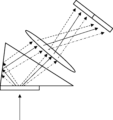
- the liquid crystal diffraction element 12 separates the incident light, but as described above, the liquid crystal diffraction element 12 diffracts right-handed circularly polarized light and left-handed circularly polarized light, although the diffraction directions are opposite. , if the wavelengths are the same, the diffraction angles are the same. Therefore, as shown in FIG. 9 by solid lines, broken lines, and dashed-dotted lines, one of the separated lights is diffracted in the direction of arrow X (to the right in the figure), and the other is specularly reflected by the second surface of the prism 14.
- the two lights that are separated and separated by diffraction by the liquid crystal diffraction element 12 become parallel lights and exit from the third surface of the prism 14 .
- the broken line is, for example, blue light
- the solid line is, for example, green light
- the dashed line is, for example, red light.
- the optical element 10 of the present invention two lights (diffraction lights) separated by the liquid crystal diffraction element 12 can be easily utilized.
- the utilization efficiency of the light separated by the liquid crystal diffraction element 12 can be improved.
- the lens 16 is placed facing the third surface of the prism 14 to focus the light, the parallel light will be focused at the same position, so it will be easier to move the liquid crystal diffraction element 12
- the two separated lights can be photometered by one detector 18. That is, according to the present invention, the utilization efficiency of the light separated by the liquid crystal diffraction element 12 can be improved. Further, as shown in FIG.
- the optical element 10 of the present invention has a simple and compact configuration in which the optical element 10 is combined with one lens 16 and one detector 18, and can be used, for example, in a spectrometer. Can be configured. That is, according to the optical element 10 of the present invention, it is possible to downsize the optical system.
- the material for forming the prism 14 is not limited, and all of the various materials used for various prisms can be used.
- the difference in refractive index between the prism 14 and the liquid crystal diffraction element 12 is small.
- the refractive index difference between the prism 14 and the liquid crystal diffraction element 12 is preferably ⁇ 0.5 or less, more preferably ⁇ 0.3 or less.
- the second surface 14a of the prism 14 that is, the surface of the prism 14 that reflects one of the lights separated by the liquid crystal diffraction element 12, totally reflects this light. That is, it is preferable that the liquid crystal diffraction element 12 diffracts the incident light so that one of the separated lights is incident on the second surface 14a of the prism 14 at an angle equal to or greater than the critical angle.
- the angle of diffraction of circularly polarized light by the liquid crystal diffraction element 12 is determined by " ⁇ / ⁇ " depending on one period ⁇ of the optically anisotropic layer 26 and the wavelength ⁇ of the incident light. Therefore, in the optical element 10 of the present invention, the optical anisotropy is adjusted so that the incident angle of the light incident on the second surface 14a of the prism 14 is equal to or greater than the critical angle, depending on the wavelength of the light to be subjected to spectroscopy. Preferably, one period ⁇ of layer 26 is determined. Furthermore, if the angle of incidence of light incident on the second surface 14a is too large, the size of the prism 14 will become large.
- one period ⁇ it is also preferable to determine one period ⁇ so that the angle of incidence of light incident on the second surface 14a does not become large and the size of the prism 14 does not become large.
- the wavelength ⁇ of the light to be subjected to spectroscopy is 450 nm
- one period ⁇ is 0.3 to 2 ⁇ m.
- the wavelength ⁇ of the light to be analyzed is 550 nm
- one period ⁇ is 0.4 to 3 ⁇ m.
- the wavelength ⁇ of the light to be subjected to spectroscopy is 700 nm, it is preferable that one period ⁇ is 0.5 to 4 ⁇ m.
- the wavelength ⁇ of the light to be subjected to spectroscopy is 1000 nm
- one period ⁇ is 0.8 to 5 ⁇ m.
- the incident light that enters the optical element 10 of the present invention is from the normal direction of the liquid crystal diffraction element 12, but the present invention is not limited to this. That is, the light may be incident on the optical element 10 (liquid crystal diffraction element 12) of the present invention from a direction having an angle with respect to the normal direction of the liquid crystal diffraction element 12. Therefore, in this case, in addition to the wavelength of the light to be separated, the optical system is adjusted so that the angle of incidence of the light on the second surface 14a of the prism 14 is equal to or less than the critical angle, depending on the set angle of incidence of the incident light. Preferably, one period ⁇ of the anisotropic layer 26 is determined. Alternatively, the angle of incidence of light on the optical element 10 (liquid crystal diffraction element 12) of the present invention may be adjusted so that the angle of incidence of light on the second surface 14a of the prism 14 is equal to or less than the critical angle.
- the second surface 14a of the prism 14 is not limited to total reflection of light.
- light may be regularly reflected on the second surface 14a of the prism 14 by providing a reflective film such as a dielectric multilayer film or a metal film on the second surface 14a of the prism 14.
- a reflective film such as a dielectric multilayer film or a metal film on the second surface 14a of the prism 14.
- the utilization efficiency of the light separated by the liquid crystal diffraction element 12 by making one of the lights separated by the liquid crystal diffraction element 12 incident at an angle equal to or greater than the critical angle, all of the light is absorbed by the second surface 14a of the prism 14.
- Preferably reflective is preferferably reflective.
- the illustrated optical element 10 has a prism 14 having a first surface on which the liquid crystal diffraction element 12 is disposed, and a second surface 14a that reflects one of the lights diffracted and separated by the liquid crystal diffraction element 12. are orthogonal. More specifically, in the optical element 10, the main surface of the liquid crystal diffraction element 12 (optically anisotropic layer 26) and the second surface of the prism 14 are perpendicular to each other. However, in the optical element of the present invention, the angle between the first surface (principal surface of the liquid crystal diffraction element 12) and the second surface of the prism 14 may be in various forms other than orthogonal.
- the incident angle (incidence direction) of the light deviates from the normal direction of the first surface of the prism 14, the same effect can be obtained by deviating the angle between the first surface and the second surface 14a from orthogonal.
- the effect of making one diffracted light from the first surface and the other diffracted light from the first surface reflected by the second surface 14a parallel to each other can be obtained.
- one direction in which the optical axis rotates in the optically anisotropic layer 26 (arrow X direction) is parallel to the direction of the diffraction vector of the second surface 14a, that is, the direction in which the periodic structure of the diffraction element repeats. is preferred.
- the normal direction of the second surface 14a and the direction of arrow X are parallel. Further, it is preferable that the direction of the arrow X is included within a plane perpendicular to the first surface and the second surface 14a. Furthermore, it is desirable that the line (ridge line) formed by the angle between the first surface and the second surface 14a of the prism 14 be orthogonal to the direction of the arrow X.
- the angle formed between the first surface and the second surface of the prism 14 may be an obtuse angle, as in the optical element 10A conceptually shown in FIG.
- the light travels in the direction of separation and is emitted from the third surface.
- This optical element as conceptually shown in FIG.
- the intensity of the light separated into right-handed circularly polarized light R and left-handed circularly polarized light L can be measured using the instrument 18.
- the angle formed between the first surface and the second surface of the prism 14 may be an acute angle.
- the light diffracted by the liquid crystal diffraction element 12 in the direction of arrow X (rightward) and the light diffracted in the opposite direction and reflected by the second surface 14a of the prism 14 are brought close to each other. The light travels in the direction and is emitted from the third surface (see FIG. 14).
- the angle between the first surface (principal surface of the liquid crystal diffraction element 12) and the second surface of the prism 14 is preferably 70 to 110 degrees, more preferably 80 to 110 degrees, and even more preferably 90 degrees.
- the angle between the first and second surfaces of the prism 14 is preferably 70 to 110 degrees, it is possible to more reliably improve the utilization efficiency of the separated light, and to detect the spectroscopy of light according to the polarization in a close range. It is preferable because it can be done.
- the liquid crystal diffraction element 12 is basically arranged parallel to the first surface of the prism 14. Therefore, in the above explanation, the angle formed between the first surface and the second surface 14a of the prism 14 is explained, but the most important point is that the main surface and the second surface 14a of the liquid crystal diffraction element 12 (optically anisotropic layer 26) is the angle formed by
- both of the two lights separated by the liquid crystal diffraction element 12 are emitted from the third surface of the prism 14. Therefore, the angle formed by the first and second surfaces 14a and the third surface is appropriately set so that the light incident on the third surface can be emitted without being reflected.
- the first surface and The angle between the prism 14 and the third surface, which is the light exit surface is preferably 5 to 60 degrees, more preferably 10 to 45 degrees.
- a retardation layer 19 is provided on the surface of the prism 14 that reflects one of the lights separated by the liquid crystal diffraction element 12, as in the optical element 10B conceptually shown in FIG. It's okay.
- the prism 14 has a retardation layer 19, one of the lights separated by the liquid crystal diffraction element 12 is reflected after having its phase adjusted by the retardation layer 19.
- the retardation layer 19 There is no limit to the retardation layer 19, and various known retardation layers can be used. Furthermore, there is no limit to the retardation provided by the retardation layer 19. Note that in order to prevent reflection at the interface between the prism 14 and the retardation layer 19, it is preferable that the prism 14 and the retardation layer 19 have similar refractive indexes. Specifically, the difference in refractive index between the prism 14 and the retardation layer 19 is preferably ⁇ 0.5 or less, more preferably ⁇ 0.3 or less.
- the prism 14 is a triangular prism, and the light separated by the liquid crystal diffraction element 12 disposed on the first surface is reflected by one side directly and the other by the second surface 14a. , the light is emitted from a third surface different from the first surface and the second surface 14a.
- the present invention is not limited to this.
- the two lights are separated by one or more surfaces of the prism. may be reflected, and two lights (diffraction lights) may be emitted from the first surface where the liquid crystal diffraction element 12 is arranged, other than the area where the liquid crystal diffraction element is arranged.
- one of the lights separated by the liquid crystal diffraction element 12 and the light reflected by the second surface are made parallel, and then the two lights are reflected by one or more surfaces of the prism, and the light is produced for the first time in the prism. Two lights (diffraction lights) may be emitted from the incident surface.
- the two lights separated by the liquid crystal diffraction element 12 are made parallel, the two lights are reflected on the same surface.
- Various configurations can be used for the propagation of light within the prism. However, whatever the configuration, it is preferable that the two lights separated by the liquid crystal diffraction element 12 be emitted from the same surface of the prism.
- Example 1 ⁇ Preparation of liquid crystal diffraction element> (Formation of alignment film)
- a glass substrate manufactured by Corning, EAGLE
- the following coating solution for forming an alignment film was applied onto the support by spin coating.
- the support on which the coating film of the coating liquid for forming an alignment film was formed was dried on a hot plate at 60° C. for 60 seconds to form an alignment film.
- Coating liquid for forming alignment film ⁇
- the following photo-alignment material 1.00 parts by mass ⁇ Water 16.00 parts by mass ⁇ Butoxyethanol 42.00 parts by mass ⁇ Propylene glycol monomethyl ether 42.00 parts by mass ⁇ ⁇
- the alignment film was exposed by irradiating the formed alignment film with polarized ultraviolet light (50 mJ/cm 2 , using an ultra-high pressure mercury lamp).
- the alignment film was exposed using the exposure apparatus shown in FIG. 7 to form an alignment film having an alignment pattern.
- a laser that emits a laser beam having a wavelength (325 nm) was used.
- the exposure amount by interference light was 300 mJ/cm 2 .
- the intersecting angle (intersecting angle ⁇ ) of the two laser beams was adjusted so that one period ⁇ (length of rotation of the optical axis by 180°) of the alignment pattern formed by the interference of the two laser beams was 1 ⁇ m. did.
- composition B-1 (Formation of optically anisotropic layer (liquid crystal layer))
- the following composition B-1 was prepared as a liquid crystal composition for forming an optically anisotropic layer.
- Rod-shaped liquid crystal compound L-1 (contains the following structure in the mass ratio shown on the right)
- the optically anisotropic layer was formed by applying composition B-1 in multiple layers on the alignment film. Specifically, the first layer of composition B-1 is coated on the alignment film, heated, cooled, and then cured with ultraviolet rays to create a liquid crystal fixing layer. The coating was repeated in layers, followed by heating, cooling, and then UV curing.
- composition B-1 was applied onto the alignment film, and the coating film was heated to 80° C. on a hot plate. Thereafter, the orientation of the liquid crystal compound was fixed by irradiating the coating film with ultraviolet light having a wavelength of 365 nm at a dose of 300 mJ/cm 2 using a high-pressure mercury lamp in a nitrogen atmosphere at 80°C.
- this liquid crystal fixing layer was overcoated, heated under the same conditions as above, and after cooling, ultraviolet curing was performed to produce a liquid crystal fixing layer. In this way, overcoating was repeated until the total thickness reached the desired thickness to form an optically anisotropic layer.
- the refractive index difference ⁇ n of the cured layer of Composition B-1 is determined by coating Composition B-1 on a separately prepared support with an alignment film for retardation measurement, and making sure that the director of the liquid crystal compound is parallel to the substrate.
- the retardation Re ( ⁇ ) and film thickness of the liquid crystal fixed layer obtained by aligning the liquid crystal so as to have the following properties and then fixing it by irradiating ultraviolet rays were determined.
- ⁇ n ⁇ can be calculated by dividing the retardation Re( ⁇ ) by the film thickness.
- the retardation Re ( ⁇ ) was measured at a desired wavelength using Axoscan from Axometrix, and the film thickness was measured using a SEM (Scanning Electron Microscope).
- the refractive index ne ( ⁇ ) for extraordinary light and the refractive index no ( ⁇ ) for ordinary light were measured using an Abbe refractometer. Further, the refractive index difference ⁇ n( ⁇ ) was determined from the difference between ne( ⁇ ) and no( ⁇ ). In the expressions Re( ⁇ ), ne( ⁇ ), no( ⁇ ), and ⁇ n( ⁇ ), ⁇ is the wavelength of the incident light. In the following, the wavelength ⁇ of the incident light was 633 nm.
- the formed optically anisotropic layer was transferred and bonded to the bottom surface of the prepared triangular prism.
- This triangular prism is made of optical glass with model number SK2 manufactured by SCHOTT, and has a refractive index of 1.605 at a wavelength of 633 nm.
- the prepared triangular prism has one angle of 90°. Further, the angle of the slope (hytenuse side) of the triangular prism is 20°.
- the optically anisotropic layer was bonded to the surface sandwiched between the right angle and the 20° angle of the triangular prism. The bonding was performed by direct bonding using plasma treatment to enhance adhesion.
- the lamination direction of the optically anisotropic layer is the direction in which the direction of the optical axis of the liquid crystal compound in the optically anisotropic layer changes while rotating, that is, the direction of the diffraction vector in the plane of the optically anisotropic layer (bright and dark lines). (direction perpendicular to the prism) is made to be perpendicular to the direction of the straight line formed by the right angle of the triangular prism. In this way, an optical element was produced.
- composition B-2 was prepared in order to form a first optically anisotropic layer in which a liquid crystal compound was oriented in a right-handed spiral in the thickness direction.
- Composition B-2 ⁇ - Rod-shaped liquid crystal compound L-1 100.00 parts by mass - Chiral agent Ch-A 0.23 parts by mass - Polymerization initiator (manufactured by BASF, Irgacure (registered trademark) 907) 3.00 parts by mass photosensitizer (Nippon Kayaku, KAYACURE DETX-S) 1.00 parts by mass ⁇ Leveling agent T-1 0.08 parts by mass ⁇ Methyl ethyl ketone 2000.00 parts by mass ⁇ ⁇
- a first optically anisotropic layer was formed on the alignment film by applying multiple layers of composition B-2 in the same manner as in Example 1 (composition B-1).
- the twist angle in the thickness direction of the liquid crystal compound was 70° (right twist).
- diagonal bright and dark lines were observed with respect to the lower interface of the optically anisotropic layer (interface with the support). These diagonal bright and dark lines are observed due to the structure in which the liquid crystal compound is twisted and oriented in a spiral shape in the thickness direction.
- composition B-3 Liquid crystal compound L-1 100.00 parts by mass Chiral agent Ch-B 0.39 parts by mass Polymerization initiator (manufactured by BASF, Irgacure (registered trademark) 907) 3.00 parts by mass photosensitizer (Nippon Kayaku, KAYACURE DETX-S) 1.00 parts by mass Leveling agent T-1 0.08 parts by mass Methyl ethyl ketone 2000.00 parts by mass ⁇ ⁇
- a second optically anisotropic layer was formed on the first optically anisotropic layer in the same manner as the first optically anisotropic layer except that Composition B-3 was used.
- An optical element was produced in the same manner as in Example 1 using the produced two optically anisotropic layers.
- Example 3 As triangular prisms, triangular prisms having apex angles of 80°, 20°, and 80° were prepared. This triangular prism is made of optical glass with model number SK2 manufactured by SCHOTT, and has a refractive index of 1.605 at a wavelength of 633 nm. The 90° angle in Example 1 was replaced with an 80° corner, and the optically anisotropic layer prepared in Example 2 was placed on the surface sandwiched between the 80° corner and the 20° corner of this triangular prism. An optical element was produced by bonding in the same manner as in Example 1.
- each angle is shown in the table below.
- the spectroscopic system was constructed in such a way that a line (image) sensor captures signals collected by a condensing lens for each wavelength after the exit surface.
- a line (image) sensor captures signals collected by a condensing lens for each wavelength after the exit surface.
- light of 550 nm could be analyzed with high efficiency of 95% or more.
- spectroscopy was possible with high efficiency of 50% or more at 400 nm and 700 nm, and 20% or more at 1000 nm.
- the ⁇ 1st-order light separated into the left and right by the diffraction element that is, the two diffracted lights separated in different directions depending on the polarization, are focused at different focal positions. is completed. That is, it can be seen that by using the optical element of Example 3, it functions as a polarization spectroscopy system that can perform spectroscopy according to polarization.
Landscapes
- Physics & Mathematics (AREA)
- General Physics & Mathematics (AREA)
- Optics & Photonics (AREA)
- Spectroscopy & Molecular Physics (AREA)
- Polarising Elements (AREA)
- Optical Head (AREA)
- Diffracting Gratings Or Hologram Optical Elements (AREA)
- Liquid Crystal (AREA)
Priority Applications (3)
| Application Number | Priority Date | Filing Date | Title |
|---|---|---|---|
| JP2024541578A JPWO2024038894A1 (https=) | 2022-08-18 | 2023-08-17 | |
| CN202380053635.5A CN119546988A (zh) | 2022-08-18 | 2023-08-17 | 光学元件 |
| US19/008,361 US20250138227A1 (en) | 2022-08-18 | 2025-01-02 | Optical element |
Applications Claiming Priority (2)
| Application Number | Priority Date | Filing Date | Title |
|---|---|---|---|
| JP2022-130696 | 2022-08-18 | ||
| JP2022130696 | 2022-08-18 |
Related Child Applications (1)
| Application Number | Title | Priority Date | Filing Date |
|---|---|---|---|
| US19/008,361 Continuation US20250138227A1 (en) | 2022-08-18 | 2025-01-02 | Optical element |
Publications (1)
| Publication Number | Publication Date |
|---|---|
| WO2024038894A1 true WO2024038894A1 (ja) | 2024-02-22 |
Family
ID=89941729
Family Applications (1)
| Application Number | Title | Priority Date | Filing Date |
|---|---|---|---|
| PCT/JP2023/029708 Ceased WO2024038894A1 (ja) | 2022-08-18 | 2023-08-17 | 光学素子 |
Country Status (4)
| Country | Link |
|---|---|
| US (1) | US20250138227A1 (https=) |
| JP (1) | JPWO2024038894A1 (https=) |
| CN (1) | CN119546988A (https=) |
| WO (1) | WO2024038894A1 (https=) |
Cited By (1)
| Publication number | Priority date | Publication date | Assignee | Title |
|---|---|---|---|---|
| WO2025183175A1 (ja) * | 2024-03-01 | 2025-09-04 | 富士フイルム株式会社 | 導光素子、および、ar表示デバイス |
Citations (6)
| Publication number | Priority date | Publication date | Assignee | Title |
|---|---|---|---|---|
| WO2008142723A2 (en) * | 2007-05-18 | 2008-11-27 | Universita' Della Calabria | Method and device for measuring circular dichroism in real time |
| US20170003169A1 (en) * | 2015-07-05 | 2017-01-05 | Purdue Research Foundation | Sub-millimeter real-time circular dichroism spectrometer with metasurfaces |
| WO2019111800A1 (ja) * | 2017-12-07 | 2019-06-13 | 横河電機株式会社 | 分光分析装置 |
| JP2020512584A (ja) * | 2017-03-21 | 2020-04-23 | マジック リープ, インコーポレイテッドMagic Leap,Inc. | 薄型ビームスプリッタ |
| WO2021132630A1 (ja) * | 2019-12-27 | 2021-07-01 | 富士フイルム株式会社 | ハイパースペクトルセンサー、ハイパースペクトルカメラ |
| WO2021235416A1 (ja) * | 2020-05-20 | 2021-11-25 | 富士フイルム株式会社 | 透過型液晶回折素子 |
-
2023
- 2023-08-17 CN CN202380053635.5A patent/CN119546988A/zh active Pending
- 2023-08-17 JP JP2024541578A patent/JPWO2024038894A1/ja active Pending
- 2023-08-17 WO PCT/JP2023/029708 patent/WO2024038894A1/ja not_active Ceased
-
2025
- 2025-01-02 US US19/008,361 patent/US20250138227A1/en active Pending
Patent Citations (6)
| Publication number | Priority date | Publication date | Assignee | Title |
|---|---|---|---|---|
| WO2008142723A2 (en) * | 2007-05-18 | 2008-11-27 | Universita' Della Calabria | Method and device for measuring circular dichroism in real time |
| US20170003169A1 (en) * | 2015-07-05 | 2017-01-05 | Purdue Research Foundation | Sub-millimeter real-time circular dichroism spectrometer with metasurfaces |
| JP2020512584A (ja) * | 2017-03-21 | 2020-04-23 | マジック リープ, インコーポレイテッドMagic Leap,Inc. | 薄型ビームスプリッタ |
| WO2019111800A1 (ja) * | 2017-12-07 | 2019-06-13 | 横河電機株式会社 | 分光分析装置 |
| WO2021132630A1 (ja) * | 2019-12-27 | 2021-07-01 | 富士フイルム株式会社 | ハイパースペクトルセンサー、ハイパースペクトルカメラ |
| WO2021235416A1 (ja) * | 2020-05-20 | 2021-11-25 | 富士フイルム株式会社 | 透過型液晶回折素子 |
Cited By (1)
| Publication number | Priority date | Publication date | Assignee | Title |
|---|---|---|---|---|
| WO2025183175A1 (ja) * | 2024-03-01 | 2025-09-04 | 富士フイルム株式会社 | 導光素子、および、ar表示デバイス |
Also Published As
| Publication number | Publication date |
|---|---|
| CN119546988A (zh) | 2025-02-28 |
| JPWO2024038894A1 (https=) | 2024-02-22 |
| US20250138227A1 (en) | 2025-05-01 |
Similar Documents
| Publication | Publication Date | Title |
|---|---|---|
| JP7427077B2 (ja) | 光学素子、画像表示ユニットおよびヘッドマウントディスプレイ | |
| JP7153087B2 (ja) | 導光素子、画像表示装置およびセンシング装置 | |
| WO2021235416A1 (ja) | 透過型液晶回折素子 | |
| JP7394794B2 (ja) | 反射光学素子、導光素子および画像表示素子 | |
| WO2019221294A1 (ja) | 光学素子 | |
| JP2017522601A (ja) | ブラッグ液晶偏光格子 | |
| JP7561763B2 (ja) | 画像表示装置 | |
| WO2020122119A1 (ja) | 液晶回折素子および導光素子 | |
| US20210389513A1 (en) | Liquid crystal optical element and fabrication method thereof | |
| JP7555356B2 (ja) | ハイパースペクトルセンサー、ハイパースペクトルカメラ | |
| CN115210615B (zh) | 消色差光学器件 | |
| JPWO2020075702A1 (ja) | 光学素子および画像表示装置 | |
| CN115989433A (zh) | 图像显示单元及头戴式显示器 | |
| JP7541104B2 (ja) | 透過型液晶回折素子 | |
| WO2024185846A1 (ja) | 液晶偏光干渉素子、光学フィルターおよび光学システム | |
| JP7470775B2 (ja) | 光結合システムおよび光通信デバイス | |
| JPWO2020075740A1 (ja) | 光学積層体、導光素子およびar表示デバイス | |
| US20250138227A1 (en) | Optical element | |
| WO2024111518A1 (ja) | 画像表示装置 | |
| WO2024057917A1 (ja) | 光学素子および光学センサー | |
| WO2023100916A1 (ja) | 光学素子および光学センサー | |
| WO2023101014A1 (ja) | ビームコンバイナ、配向膜の形成方法、および、光学素子の製造方法 | |
| CN120898156A (zh) | 液晶衍射元件及光学器件 | |
| WO2022239858A1 (ja) | 光学素子および光学センサー | |
| WO2022211026A1 (ja) | ビームコンバイナ、配向膜の形成方法、および、光学素子の製造方法 |
Legal Events
| Date | Code | Title | Description |
|---|---|---|---|
| 121 | Ep: the epo has been informed by wipo that ep was designated in this application |
Ref document number: 23854928 Country of ref document: EP Kind code of ref document: A1 |
|
| WWE | Wipo information: entry into national phase |
Ref document number: 2024541578 Country of ref document: JP |
|
| WWE | Wipo information: entry into national phase |
Ref document number: 202380053635.5 Country of ref document: CN |
|
| WWP | Wipo information: published in national office |
Ref document number: 202380053635.5 Country of ref document: CN |
|
| NENP | Non-entry into the national phase |
Ref country code: DE |
|
| 122 | Ep: pct application non-entry in european phase |
Ref document number: 23854928 Country of ref document: EP Kind code of ref document: A1 |