WO2024038528A1 - Dispositif d'inhalation, procédé de commande et programme - Google Patents
Dispositif d'inhalation, procédé de commande et programme Download PDFInfo
- Publication number
- WO2024038528A1 WO2024038528A1 PCT/JP2022/031132 JP2022031132W WO2024038528A1 WO 2024038528 A1 WO2024038528 A1 WO 2024038528A1 JP 2022031132 W JP2022031132 W JP 2022031132W WO 2024038528 A1 WO2024038528 A1 WO 2024038528A1
- Authority
- WO
- WIPO (PCT)
- Prior art keywords
- suction device
- heating
- authentication process
- temperature
- control
- Prior art date
Links
- 238000000034 method Methods 0.000 title claims abstract description 240
- 238000010438 heat treatment Methods 0.000 claims abstract description 404
- 230000008569 process Effects 0.000 claims abstract description 228
- 239000000443 aerosol Substances 0.000 claims abstract description 140
- 239000000463 material Substances 0.000 claims abstract description 48
- 238000012545 processing Methods 0.000 claims description 19
- 239000003086 colorant Substances 0.000 claims description 5
- 239000000758 substrate Substances 0.000 claims description 3
- 239000000796 flavoring agent Substances 0.000 description 31
- 235000019634 flavors Nutrition 0.000 description 31
- 238000010586 diagram Methods 0.000 description 22
- 230000007423 decrease Effects 0.000 description 21
- 238000004891 communication Methods 0.000 description 20
- 239000007788 liquid Substances 0.000 description 17
- 230000007704 transition Effects 0.000 description 13
- 230000000391 smoking effect Effects 0.000 description 11
- 241000208125 Nicotiana Species 0.000 description 10
- 235000002637 Nicotiana tabacum Nutrition 0.000 description 10
- DNIAPMSPPWPWGF-UHFFFAOYSA-N Propylene glycol Chemical compound CC(O)CO DNIAPMSPPWPWGF-UHFFFAOYSA-N 0.000 description 6
- 238000003825 pressing Methods 0.000 description 6
- 230000006866 deterioration Effects 0.000 description 5
- 230000006870 function Effects 0.000 description 5
- 210000000214 mouth Anatomy 0.000 description 5
- PEDCQBHIVMGVHV-UHFFFAOYSA-N Glycerine Chemical compound OCC(O)CO PEDCQBHIVMGVHV-UHFFFAOYSA-N 0.000 description 4
- 230000000694 effects Effects 0.000 description 4
- 230000006698 induction Effects 0.000 description 4
- 239000000126 substance Substances 0.000 description 4
- 239000012530 fluid Substances 0.000 description 3
- 230000006872 improvement Effects 0.000 description 3
- 230000004048 modification Effects 0.000 description 3
- 238000012986 modification Methods 0.000 description 3
- 239000003814 drug Substances 0.000 description 2
- 229940079593 drug Drugs 0.000 description 2
- 238000005401 electroluminescence Methods 0.000 description 2
- 238000005516 engineering process Methods 0.000 description 2
- 235000011187 glycerol Nutrition 0.000 description 2
- 239000011810 insulating material Substances 0.000 description 2
- 239000006199 nebulizer Substances 0.000 description 2
- 230000004044 response Effects 0.000 description 2
- 239000000779 smoke Substances 0.000 description 2
- 150000005846 sugar alcohols Polymers 0.000 description 2
- 235000019640 taste Nutrition 0.000 description 2
- 239000006200 vaporizer Substances 0.000 description 2
- 238000012795 verification Methods 0.000 description 2
- XLYOFNOQVPJJNP-UHFFFAOYSA-N water Substances O XLYOFNOQVPJJNP-UHFFFAOYSA-N 0.000 description 2
- HBBGRARXTFLTSG-UHFFFAOYSA-N Lithium ion Chemical compound [Li+] HBBGRARXTFLTSG-UHFFFAOYSA-N 0.000 description 1
- 230000004913 activation Effects 0.000 description 1
- 238000000889 atomisation Methods 0.000 description 1
- 230000004397 blinking Effects 0.000 description 1
- 239000000919 ceramic Substances 0.000 description 1
- 230000008859 change Effects 0.000 description 1
- 238000006243 chemical reaction Methods 0.000 description 1
- 230000003111 delayed effect Effects 0.000 description 1
- 238000013461 design Methods 0.000 description 1
- 238000001514 detection method Methods 0.000 description 1
- 230000005674 electromagnetic induction Effects 0.000 description 1
- 238000011156 evaluation Methods 0.000 description 1
- 239000002657 fibrous material Substances 0.000 description 1
- 239000003365 glass fiber Substances 0.000 description 1
- 239000004973 liquid crystal related substance Substances 0.000 description 1
- 229910001416 lithium ion Inorganic materials 0.000 description 1
- 230000007246 mechanism Effects 0.000 description 1
- 239000011148 porous material Substances 0.000 description 1
- 238000007639 printing Methods 0.000 description 1
- 230000000630 rising effect Effects 0.000 description 1
- 239000007787 solid Substances 0.000 description 1
- 238000012546 transfer Methods 0.000 description 1
- 239000012780 transparent material Substances 0.000 description 1
- 238000011144 upstream manufacturing Methods 0.000 description 1
Images


Classifications
-
- A—HUMAN NECESSITIES
- A24—TOBACCO; CIGARS; CIGARETTES; SIMULATED SMOKING DEVICES; SMOKERS' REQUISITES
- A24F—SMOKERS' REQUISITES; MATCH BOXES; SIMULATED SMOKING DEVICES
- A24F40/00—Electrically operated smoking devices; Component parts thereof; Manufacture thereof; Maintenance or testing thereof; Charging means specially adapted therefor
- A24F40/50—Control or monitoring
- A24F40/57—Temperature control
Definitions
- the present invention relates to a suction device, a control method, and a program.
- a suction device that generates an aerosol to which a flavor component is added and allows a user to inhale the generated aerosol.
- Such inhalers typically heat the substrate comprising the aerosol source with a heating section (also referred to as a "heating element") that is an electrical resistance or induction heater.
- the aerosol generated by this process is delivered to the user.
- some such suction devices have a so-called "child resistance feature" to prevent inconveniences due to misuse by children (e.g. infants and young children).
- a vaporizer receives information associated with a user of the vaporizer, determines the user's age based on the received information, and based on the user's age that satisfies a threshold, Techniques are disclosed that allow a carburetor to be unlocked for activation of carburetor operation.
- Patent Document 2 discloses that using technologies such as fingerprint authentication and unlocking after RFID check with a mobile device installed with an RFID reader allows the use of electronic smoking articles to be restricted to individuals with specific fingerprints or to smokers. Techniques have been disclosed that limit access to items to individuals who have a mobile device with a key.
- the present invention provides a suction device, a control method, and a program that can improve the safety and security of the suction device while suppressing a decrease in convenience accompanying the improvement in safety and security.
- the first invention is A suction device for generating an aerosol from a substrate having an aerosol source, the suction device comprising: a heating unit that heats the base material to generate the aerosol; a control unit that controls the operation of the suction device; Equipped with The control unit includes: a first heating control that controls the temperature of the heating section with a target temperature lower than the lowest temperature at which the aerosol is generated; A second heating control that controls the temperature of the heating section with a temperature higher than the minimum temperature as a target temperature, Executing the first heating control when an authentication process related to whether or not the suction device can be used is being performed; When the authentication process is completed, the first heating control is ended and the second heating control is executed. It is a suction device.
- the second invention is A computer includes a heating unit that heats a base material having an aerosol source, and controls an operation of a suction device that generates an aerosol by heating the base material with the heating unit,
- first heating control is executed to control the temperature of the heating section with a target temperature lower than the lowest temperature at which the aerosol is generated.
- the first heating control is ended, and a second heating control is executed to control the temperature of the heating section with a temperature higher than the minimum temperature as a target temperature. This is a control method for processing.
- the third invention is A computer includes a heating unit that heats a base material having an aerosol source, and controls the operation of a suction device that generates an aerosol by heating the base material with the heating unit,
- first heating control is executed to control the temperature of the heating section with a target temperature lower than the lowest temperature at which the aerosol is generated.
- the first heating control is ended, and a second heating control is executed to control the temperature of the heating section with a temperature higher than the minimum temperature as a target temperature.
- This is a program that performs processing.
- the present invention it is possible to provide a suction device, a control method, and a program that can improve the safety and security of the suction device while suppressing a decrease in convenience accompanying the improvement in safety and security.
- FIG. 1A is a schematic diagram schematically showing a first configuration example of a suction device.
- FIG. 1B is a schematic diagram schematically showing a second configuration example of the suction device.
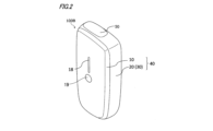
- FIG. 2 is an overall perspective view of the suction device 100B.
- FIG. 3 is a top view of the suction device 100B.
- FIG. 4 is a diagram showing the suction device 100B with the panel 10 removed.
- FIG. 5 is a diagram showing a first example of the temperature transition of the heating unit 121B due to the heating control during authentication and the main heating control.
- FIG. 6 is a diagram showing a second example of the temperature transition of the heating unit 121B due to the heating control during authentication and the main heating control.
- FIG. 7 is a diagram showing a third example of the temperature transition of the heating unit 121B due to the heating control during authentication and the main heating control.
- FIG. 8 is a diagram showing a first example of notification of progress information.
- FIG. 9 is a diagram showing a modification of the light emitting device 23a.
- FIG. 10 is a diagram showing a second example of notification of progress information.
- FIG. 11 is a diagram showing an example of the display device 23b.
- FIG. 12 is a diagram showing a third example of notification of progress information.
- FIG. 13 is a flowchart illustrating an example of processing executed by the control unit 116B.
- the suction device of this embodiment is a device that generates a substance that is suctioned by a user.
- the substance generated by the suction device is an aerosol.
- the substance produced by the suction device may be a gas.
- FIG. 1A is a schematic diagram schematically showing a first configuration example of a suction device.
- a suction device 100A includes a power supply unit 110, a cartridge 120, and a flavor imparting cartridge 130.
- the power supply unit 110 includes a power supply section 111A, a sensor section 112A, a notification section 113A, a storage section 114A, a communication section 115A, and a control section 116A.
- the cartridge 120 includes a heating section 121A, a liquid guiding section 122, and a liquid storage section 123.
- Flavoring cartridge 130 includes a flavor source 131 and a mouthpiece 124 .
- An air flow path 180 is formed in the cartridge 120 and the flavoring cartridge 130.
- the power supply unit 111A stores power.
- the power supply section 111A supplies power to each component of the suction device 100A under the control of the control section 116A.
- the power supply unit 111A may be configured with a rechargeable battery such as a lithium ion secondary battery, for example.
- the sensor unit 112A acquires various information regarding the suction device 100A.
- the sensor unit 112A includes a pressure sensor such as a condenser microphone, a flow rate sensor, a temperature sensor, etc., and acquires a value associated with suction by the user.
- the sensor unit 112A is configured with an input device such as an operation button or a switch that receives information input from the user.
- the sensor unit 112A includes a pressure sensor (also referred to as a "puff sensor”) that detects a change in the pressure (i.e., internal pressure) within the suction device 100A caused by suction by the user.
- the sensor unit 112A also includes a flow rate sensor that detects the flow rate generated by suction by the user, a temperature sensor (also referred to as a "puff thermistor”) that detects the heating unit 121A or the temperature around the heating unit 121A, and the like. You may be
- the notification unit 113A notifies the user of information.
- the notification unit 113A is configured by, for example, a light emitting device that emits light (for example, a light emitting device 23a described below), a display device that displays an image (for example, a display device 23b that will be described later), a sound output device that outputs sound, a vibration device that vibrates, or the like. configured.
- the storage unit 114A stores various information for the operation of the suction device 100A.
- the storage unit 114A is composed of, for example, a nonvolatile storage medium such as a flash memory.
- the communication unit 115A is a communication interface that can perform communication compliant with any wired or wireless communication standard.
- Such communication standards include, for example, Wi-Fi (registered trademark), Bluetooth (registered trademark), BLE (Bluetooth Low Energy (registered trademark)), NFC (Near Field Communication), or LPWA (Low Power Wide Area). Standards etc. may be adopted.
- the control unit 116A functions as an arithmetic processing device and a control device, and controls overall operations within the suction device 100A according to various programs.
- the control unit 116A is realized by, for example, an electronic circuit such as a CPU (Central Processing Unit) or a microprocessor.
- the liquid storage section 123 stores an aerosol source. That is, the cartridge 120 having the liquid storage section 123 that stores an aerosol source is an example of a base material having an aerosol source. Aerosols are generated by atomizing the aerosol source. Aerosol sources are, for example, polyhydric alcohols such as glycerin and propylene glycol, or liquids such as water. The aerosol source may include flavor components of tobacco or non-tobacco origin. If the suction device 100A is a medical inhaler such as a nebulizer, the aerosol source may include a drug.
- the liquid guide section 122 guides and holds an aerosol source, which is a liquid stored in the liquid storage section 123, from the liquid storage section 123.
- the liquid guide portion 122 is, for example, a wick formed by twisting a fiber material such as glass fiber or a porous material such as porous ceramic. In that case, the aerosol source stored in the liquid reservoir 123 is guided by the capillary effect of the wick.
- the heating unit 121A atomizes the aerosol source to generate aerosol by heating the aerosol source.
- the heating section 121A is configured as a coil and is wound around the liquid guiding section 122.
- the heating unit 121A generates heat, the aerosol source held in the liquid guide unit 122 is heated and atomized, and an aerosol is generated.
- the heating section 121A generates heat when supplied with power from the power supply section 111A.
- the sensor unit 112A detects that the user has started suctioning and/or that predetermined information has been input, power may be supplied to the heating unit 121A.
- the power supply to the heating unit 121A may be stopped.
- the user's suction operation with respect to the suction device 100A can be detected based on, for example, the pressure (internal pressure) inside the suction device 100A detected by a puff sensor exceeding a predetermined threshold.
- the flavor source 131 is a component for imparting a flavor component to the aerosol.
- Flavor source 131 may include tobacco-derived or non-tobacco-derived flavor components.
- the air flow path 180 is a flow path for air drawn in by the user.
- the air flow path 180 has a tubular structure having an air inflow hole 181 that is an inlet of air into the air flow path 180 and an air outflow hole 182 that is an outlet of air from the air flow path 180 at both ends.
- the liquid guide part 122 is arranged on the upstream side (closer to the air inlet hole 181), and the flavor source 131 is arranged on the downstream side (closer to the air outlet hole 182).
- Air flowing in through the air inflow hole 181 as a result of suction by the user is mixed with the aerosol generated by the heating unit 121A, and is transported to the air outflow hole 182 through the flavor source 131 as shown by arrow 190.
- flavor components contained in the flavor source 131 are imparted to the aerosol.
- the mouthpiece 124 is a member that is held in the user's mouth during suction.
- An air outlet hole 182 is arranged in the mouthpiece 124 . The user can take the mixed fluid of aerosol and air into the oral cavity by sucking the mouthpiece 124 in the mouth.
- suction device 100A has been described above.
- the configuration of the suction device 100A is not limited to the above, and may take various configurations as exemplified below.
- the suction device 100A may not include the flavor imparting cartridge 130.
- the cartridge 120 is provided with a mouthpiece 124.
- the suction device 100A may further include a second heating section that heats the flavor source 131.
- the second heating section is configured in a film shape, for example, and is arranged to cover the outer periphery of the flavor imparting cartridge 130.
- the second heating section generates heat when supplied with electric power from the power supply section 111A, and heats the flavor imparting cartridge 130 from the outer periphery.
- the second heating section is controlled so that the actual temperature becomes a predetermined target temperature, for example, similarly to the heating section 121B described later.
- the suction device 100A including such a second heating section will also be referred to as a "hybrid suction device 100A.”
- the suction device 100A may include multiple types of aerosol sources.
- Other types of aerosols may be generated by mixing a plurality of types of aerosols generated from a plurality of types of aerosol sources in the air flow path 180 and causing a chemical reaction.
- the means for atomizing the aerosol source is not limited to heating by the heating unit 121A.
- the means of atomizing the aerosol source may be vibratory atomization, or induction heating.
- FIG. 1B is a schematic diagram schematically showing a second configuration example of the suction device.
- the suction device 100B according to the present configuration example includes a power supply section 111B, a sensor section 112B, a notification section 113B, a storage section 114B, a communication section 115B, a control section 116B, a heating section 121B, a storage section 140, and A heat insulating section 144 is included.
- Each of the power supply unit 111B, sensor unit 112B, notification unit 113B, storage unit 114B, communication unit 115B, and control unit 116B is substantially the same as the corresponding component included in the suction device 100A according to the first configuration example. It is.
- the accommodating part 140 has an internal space 141, and holds the stick-type base material 150 while accommodating a part of the stick-type base material 150 in the internal space 141.
- the accommodating part 140 has an opening 142 that communicates the internal space 141 with the outside, and accommodates the stick-shaped base material 150 inserted into the internal space 141 from the opening 142.
- the accommodating portion 140 is a cylindrical body having an opening 142 and a bottom portion 143 as a bottom surface, and defines a columnar internal space 141 .
- An air flow path that supplies air to the internal space 141 is connected to the housing section 140 .
- An air inflow hole which is an inlet of air to the air flow path, is arranged on a side surface of the suction device 100, for example.
- An air outlet hole which is an outlet for air from the air flow path to the internal space 141, is arranged at the bottom 143, for example.
- the stick-type base material 150 includes a base portion 151 and a mouthpiece portion 152.
- Base portion 151 includes an aerosol source. That is, the stick-type base material 150 is another example of a base material containing an aerosol source.
- the aerosol source includes flavor components of tobacco or non-tobacco origin. If the suction device 100B is a medical inhaler such as a nebulizer, the aerosol source may include a drug.
- the aerosol source may be, for example, a liquid such as polyhydric alcohols such as glycerin and propylene glycol, and water, containing flavor components of tobacco or non-tobacco origin, and containing flavor components of tobacco or non-tobacco origin. It may be solid.
- the heating section 121B is configured in a film shape and is arranged to cover the outer periphery of the housing section 140.
- the heating part 121B generates heat
- the base material part 151 of the stick-type base material 150 is heated from the outer periphery, and an aerosol is generated.
- the heat insulating section 144 prevents heat transfer from the heating section 121B to other components.
- the heat insulating section 144 is made of a vacuum heat insulating material, an airgel heat insulating material, or the like.
- suction device 100B has been described above.
- the configuration of the suction device 100B is not limited to the above, and may take various configurations as exemplified below.
- the heating section 121B may be configured in a blade shape and arranged to protrude from the bottom 143 of the housing section 140 into the internal space 141.
- the blade-shaped heating section 121B is inserted into the base material part 151 of the stick-type base material 150 and heats the base material part 151 of the stick-type base material 150 from inside.
- the heating part 121B may be arranged to cover the bottom part 143 of the housing part 140.
- the heating unit 121B is a combination of two or more of a first heating unit that covers the outer periphery of the housing unit 140, a blade-shaped second heating unit, and a third heating unit that covers the bottom portion 143 of the housing unit 140. It may be configured as
- the housing section 140 may include an opening/closing mechanism such as a hinge that opens and closes a part of the outer shell that forms the internal space 141.
- the accommodating part 140 may accommodate the stick-shaped base material 150 inserted into the internal space 141 while sandwiching it by opening and closing the outer shell.
- the heating unit 121B may be provided at the relevant clamping location in the storage unit 140, and may heat the stick-shaped base material 150 while pressing it.
- the means for atomizing the aerosol source is not limited to heating by the heating unit 121B.
- the means of atomizing the aerosol source may be induction heating.
- the suction device 100B includes at least an electromagnetic induction source such as a coil that generates a magnetic field instead of the heating unit 121B.
- the susceptor that generates heat by induction heating may be provided in the suction device 100B, or may be included in the stick-shaped base material 150.
- the suction device 100B may further include a heating section 121A, a liquid guide section 122, a liquid storage section 123, and an air flow path 180 according to the first configuration example, and the air flow path 180 is connected to the internal space 141. Air may be supplied.
- the mixed fluid of the aerosol and air generated by the heating unit 121A flows into the internal space 141, is further mixed with the aerosol generated by the heating unit 121B, and reaches the user's oral cavity.
- suction device 100 is the suction device 100B shown in FIG. 1B
- the present invention is not limited to this, and may be the suction device 100A shown in FIG. 1A or the hybrid suction device 100A. The same can be said.
- FIG. 2 is an overall perspective view of the suction device 100B. Further, FIG. 3 is a top view of the suction device 100B, and specifically, FIG. (b) shows the suction device 100B with the opening 142 open.
- the suction device 100B includes a panel 10, a main body housing 20 to which the panel 10 can be attached and detached, and a shutter 50 that is slidable (that is, movable) with respect to the main body housing 20.
- the panel 10 and the main body housing 20 are constructed from separate members.
- the panel 10 is mainly composed of a member that serves as a cover that forms at least a part of the outermost housing 40 (described later) of the suction device 100B. Further, as shown in FIG. 2, the panel 10 includes a display section 18 and an operation section 19 on its surface (outer surface).
- the display section 18 is made of a transparent material through which light can pass.
- a light emitting device 23a as an example of the notification section 113B is provided inside the suction device 100B (inside the main body 30, which will be described later). The user can visually recognize the light from the light emitting device 23a from the outer surface of the panel 10 via the display section 18.
- the operating portion 19 is configured to form a recess toward the main body housing 20, for example. Thereby, the position of the operation unit 19 can be guided to the user. Further, the position of the operation section 19 may be guided to the user by printing a predetermined mark (mark) on the surface of the panel 10 or the like.
- the main body housing 20 accommodates the main body 30 of the suction device 100B.
- the main body 30 houses, for example, each component of the suction device 100B shown in FIG. 1B.
- the panel 10 By attaching the panel 10 to the main body housing 20, it constitutes the outermost housing 40 of the suction device 100B.
- the user can make the appearance of the suction device 100B suit his or her tastes by attaching a panel 10 with a design that suits his or her tastes.
- the suction device 100B can buffer the heat released to the outside even if the main body 30 generates heat. That is, the panel 10 can function, for example, to insulate heat generated from the main body 30 (eg, the heating section 121B).
- the housing 40 is preferably sized to fit in the user's hand.
- the user holds the suction device 100B with one hand while touching the surface of the panel 10 with a fingertip. Then, when the user presses the operating section 19 with a fingertip, the panel 10 is deformed so that the operating section 19 is further recessed toward the main body housing 20. As a result of such deformation of the panel 10, the bottom of the operating portion 19 comes into contact with an operating button 22 (described later) provided on the surface of the main body housing 20, and the operating button 22 is pressed down. As an example, the user can turn on the power of the suction device 100B by pushing the operation part 19 with a finger and pressing the operation button 22.
- FIGS. 2 and 3(a) show the suction device 100B with the opening 142 closed by the shutter 50.
- the suction device 100B is in the state shown in FIG. 3(a)
- the shutter 50 is moved from above the opening 142 as shown in FIG. 3(b).
- the opening 142 is opened. In this manner, the user can insert the stick-shaped base material 150 into the opening 142 by operating the shutter 50 to open the opening 142.
- FIG. 4 is a diagram showing the suction device 100B with the panel 10 removed, and specifically, the panel 10 is removed from the main body housing 20.
- the outer surface of the main body housing 20 is shown as exposed. That is, the outer surface of the main housing 20 shown in FIG. 4 is covered by the panel 10 when the panel 10 is attached to the main housing 20.
- the outer surface of the main body housing 20 is provided with, for example, a magnet 21a, a magnet 21b, an operation button 22, and a display window 23. Further, in addition to these, a sensor for detecting attachment of the panel 10 to the main body housing 20 may be provided on the outer surface of the main body housing 20, for example.
- the magnets 21a and 21b attract the panel 10 to the main body housing 20 by magnetic force (magnetic attraction). Thereby, the panel 10 is held by the main body housing 20. More specifically, magnets (not shown) corresponding to the magnets 21a and 21b are provided on the inner surface of the panel 10, which faces the outer surface of the main body housing 20 when the panel 10 is attached to the main body housing 20. It is provided. The panel 10 is held in the main housing 20 by the magnets provided on the panel 10 and the magnets 21a and 21b being attracted to each other.
- the magnet 21a, the magnet 21b, and the magnet of the panel 10 are preferably constituted by permanent magnets, for example.
- the operation button 22 is provided at a position corresponding to the operation section 19 of the panel 10 when the panel 10 is attached to the main body housing 20. This allows the user to operate the operation button 22 via the operation unit 19 of the panel 10, as described above.
- the display window 23 is an opening aligned with the light emitting device 23a provided in the main body 30, and allows light from the light emitting device 23a to pass through to the display section 18 of the panel 10. Thereby, as described above, the user can visually recognize the light from the light emitting device 23a from the outer surface of the panel 10.
- the light emitting device 23a is an example of a light emitting section that emits light, and is composed of one or more light emitting elements, for example.
- an LED Light Emitting Diode
- the light emitting device 23a has a plurality of LEDs that emit light of different colors, and is configured to be able to emit light in a plurality of colors including blue, yellow, and red.
- the light emitting device 23a notifies the user of predetermined information by emitting light in a predetermined light emission mode.
- the light emitting mode may be, for example, the color of the emitted light, but is not limited to this, and may be, for example, the intensity of the lighting intensity (in other words, the brightness), the lighting pattern (for example, blinking at a predetermined time interval), etc. It's okay.
- Examples of notifications made by the light emitting device 23a include notifications of operation information of the suction device 100B indicating whether the power of the suction device 100B is on (that is, in a powered-on state). Further, in this embodiment, the light emitting device 23a can notify the user of information regarding the progress of the authentication process (described later).
- the control unit 116 (116A, 116B) can operate the suction device 100 based on input from the user. As an example, the control unit 116 causes the suction device 100 to generate an aerosol in response to an aerosol generation request from a user.
- the aerosol generation request can be, for example, an operation that instructs to start heating (hereinafter also referred to as "heating start operation").
- the heating start operation can be performed by pressing the operation button 22 while the suction device 100 is powered on.
- the heating start operation may be a suction operation for the suction device 100 while the suction device 100 is powered on.
- the aerosol generation request is not limited to a direct operation on the suction device 100, and may be, for example, a reception of predetermined information from another device that can communicate with the suction device 100, such as a smartphone.
- the control unit 116 can detect an aerosol generation request based on information acquired by the sensor unit 112 or the communication unit 115, for example.
- the control unit 116A detects a suction operation for the suction device 100A based on the detection result of the puff sensor, the control unit 116A supplies predetermined power to the heating unit 121A. This causes aerosol generation. At this time, the power supplied to the heating unit 121A is predetermined by the manufacturer of the suction device 100A so that an appropriate amount of aerosol containing an appropriate amount of flavor components is generated. Thereby, a high quality smoking experience can be provided to the user.
- the control section 116B when the suction device 100 is the suction device 100B shown in FIG. 1B, when the control section 116B detects a heating start operation (for example, pressing the operation button 22), the control section 116B controls the heating section 121B based on a heating profile prepared in advance. Aerosol generation is achieved by controlling the temperature.
- the heating profile is information that defines a time-series transition of the target temperature, which is the target value of the temperature of the heating section 121B, and is stored in advance in the storage section 114B, for example.
- the control section 116B corresponds to the elapsed time after starting the heating control based on the heating profile.
- the temperature of the heating section 121B is controlled based on the deviation between the target temperature and the actual temperature of the heating section 121B (hereinafter also referred to as "actual temperature”). More specifically, at this time, the control unit 116B controls the temperature of the heating unit 121B so that the time-series transition of the actual temperature of the heating unit 121B becomes similar to the time-series transition of the target temperature specified in the heating profile. control.
- the temperature control of the heating section 121B can be realized, for example, by known feedback control.
- the control unit 116B supplies power from the power supply unit 111B to the heating unit 121B in the form of pulses using pulse width modulation (PWM) or pulse frequency modulation (PFM).
- PWM pulse width modulation
- PFM pulse frequency modulation
- the control unit 116B can control the temperature of the heating unit 121B by adjusting the duty ratio of the power pulse.
- the control unit 116B may control the power supplied to the heating unit 121B, for example, the duty ratio, based on the difference between the actual temperature and the target temperature.
- the feedback control may be, for example, PID control (Proportional-Integral-Differential Controller).
- the control unit 116B may perform simple ON-OFF control. For example, the control unit 116B executes heating by the heating unit 121B until the actual temperature reaches the target temperature, and stops the heating by the heating unit 121B when the actual temperature reaches the target temperature, so that the actual temperature becomes lower than the target temperature. In this case, heating by the heating unit 121B may be performed again.
- the temperature of the heating section 121B can be obtained (in other words, quantified) by, for example, measuring or estimating the electrical resistance value of the heating resistor that constitutes the heating section 121B. This is because the electrical resistance value of the heating resistor changes depending on the temperature.
- the electrical resistance value of the heating resistor can be estimated (that is, obtained) by, for example, measuring the amount of voltage drop across the heating resistor.
- the amount of voltage drop across the heating resistor can be measured (that is, acquired) by a voltage sensor that measures the potential difference applied to the heating resistor.
- the temperature of the heating section 121B may be measured by a temperature sensor (puff thermistor) installed near the heating section 121B.
- the heating profile (for example, the heating profile for main heating control described below) is typically designed to optimize the flavor that the user experiences when the user inhales the aerosol generated from the stick-shaped base material 150. be done. Therefore, by controlling the temperature of the heating section 121B based on the heating profile, the flavor that the user enjoys can be optimized, and a high-quality smoking experience can be provided to the user.
- a suction device such as the suction device 100 that generates a substance to be inhaled by a user has a so-called "child resistance” in order to prevent problems caused by misuse by children (for example, infants and young children).
- function hereinafter also referred to as “CR function”.
- aerosol generation may be performed after the legitimacy of the user is confirmed by user authentication such as fingerprint authentication.
- the heating section that heats the aerosol source to reach a temperature sufficient to generate aerosol after the temperature of the heating section starts rising. Furthermore, if the heating of the heating section is started after the user's legitimacy is confirmed, the start of heating of the heating section is delayed accordingly, and the time until aerosol is generated becomes even longer.
- the usability of the inhaler may decrease, and the marketability of the inhaler may decrease. From the perspective of the marketability of the suction device, it is possible to improve the safety and security of the suction device by restricting its use by persons other than legitimate users (e.g. children), but there are It is desirable to suppress the decline in convenience as much as possible.
- the temperature of the heating unit 121 is increased within a range in which no aerosol is generated, starting from the time when the authentication process (hereinafter also simply referred to as "authentication process") related to whether or not the suction device 100 can be used is being performed. Do it like this.
- the temperature of the heating unit 121 can be raised in advance during the authentication process, so that the time required to raise the temperature of the heating unit 121 to the temperature at which aerosol is generated after the authentication process is completed can be shortened. Therefore, even if it is necessary to complete the authentication process to generate aerosol, the time required to generate aerosol can be suppressed from prolonging, and the convenience due to the prolongation of the time can be improved. can suppress the decline in
- the suction device 100 of this embodiment is the suction device 100B shown in FIG. 1B
- the present invention is not limited to this.
- the suction device 100 is a hybrid type suction device 100A.
- suction device 100B is replaced by “hybrid type suction device 100A”
- sensor part 112B is replaced by “sensor part 112A”
- notification part 113B is replaced by “notification part 113A”
- storage part 114B as “storage section 114A”
- communication section 115B as “communication section 115A”
- control section 116B as “control section 116A”
- heating section 121B as “second in hybrid suction device 100A.”
- ⁇ heating section that is, heating section that heats the flavor imparting cartridge 130
- control unit 116B of the suction device 100B controls the temperature of the heating unit 121B so that the actual temperature of the heating unit 121B becomes a predefined target temperature.
- control unit 116B is configured to be able to execute heating control during authentication and main heating control.
- the heating control during authentication is heating control with a target temperature lower than the minimum temperature at which aerosol is generated (hereinafter also simply referred to as "minimum temperature”), and is an example of the first heating control in the present invention. It is.
- the minimum temperature is determined by the physical characteristics of the aerosol source, and is, for example, 230 [° C.] in this embodiment.
- target temperature during authentication By setting the target temperature in heating control during authentication (hereinafter also referred to as “target temperature during authentication") to a temperature lower than the minimum temperature, it is possible to ensure that the user's legitimacy is confirmed while the authentication process is being performed (in other words, the user's legitimacy is confirmed).
- the safety and security of the suction device 100 can be improved by suppressing the generation of aerosol (before the suction device 100 is used).
- the aerosol source of the stick-shaped base material 150 is not consumed due to the temperature rise of the heating section 121B when the heating control during authentication is executed. can be suppressed. Thereby, even if heating control is executed during authentication, an appropriate amount of aerosol can be generated afterwards, making it possible to provide a high-quality smoking experience to the user.
- the stick that was heated during this authentication process It is possible to continue using the mold base material 150 thereafter.
- the target temperature during authentication can be, for example, 100 [°C].
- the target temperature during authentication is not limited to a single temperature, but may be set to multiple temperatures, such as 100 [°C], 150 [°C], and 200 [°C] (described later). .
- This heating control is heating control with a target temperature higher than the minimum temperature, and is an example of the second heating control in the present invention.
- the target temperature in the main heating control (hereinafter also referred to as “target temperature during main heating") is typically determined so as to optimize the flavor that the user enjoys when the user inhales the generated aerosol.
- the target temperature during main heating can be 240 [°C], 260 [°C], or 300 [°C], etc.
- the target temperature during the main heating changes, such as 300 [°C], 240 [°C], and 260 [°C], depending on the elapsed time after the main heating control is started. (described later).
- control unit 116B configured to be able to execute the heating control during authentication and the main heating control executes the heating control during authentication when the authentication process is being performed.
- the control unit 116B ends the heating control during authentication and executes the main heating control.
- This makes it possible to raise the temperature of the heating section 121B to the target temperature during the authentication process, and the heating section 121B is heated to the temperature at which aerosol is generated by the main heating control executed after the authentication process is completed.
- the time required for this can be shortened. Therefore, even if it is necessary to complete the authentication process to generate aerosol, the time required to generate aerosol can be suppressed from prolonging, and the convenience due to the prolongation of the time can be improved. can suppress the decline in
- “completion” of the authentication process means, for example, that the authentication process is ended after the user's legitimacy is confirmed by the authentication process. More specifically, for example, even if the authenticity of the user is not confirmed in the authentication process, a predetermined amount of time has elapsed since the start (a so-called timeout), or authentication has failed a predetermined number of times (for example, three times in a row). Although the process also ends if the authentication process is completed, such an end of the authentication process is not called “completion”. Hereinafter, such termination of the authentication process without confirming the user's authenticity will also be referred to as "interruption.”
- user authentication is performed in which the user receives input of predetermined authentication information (for example, fingerprint information described below) and verifies the user's authenticity by comparing the input authentication information with pre-stored information. executed.
- predetermined authentication information for example, fingerprint information described below
- biometric authentication such as fingerprint authentication, gesture authentication, PIN (Personal Identification Number) authentication, password authentication, voice authentication, or the like can be adopted.
- communication authentication using communication between the suction device 100B and another device that can communicate with the suction device 100B, such as a smartphone, may be adopted as the user authentication through the authentication process.
- communication authentication for example, gesture authentication or password authentication using another device can be adopted. In that case, when the user's legitimacy is confirmed through gesture authentication or password authentication, the other device transmits information to that effect to the suction device 100B.
- the control unit 116B performs authentication processing in response to detecting a heating start operation. More specifically, for example, when the control unit 116B detects that the operation button 22 is pressed while the suction device 100B is powered on, the control unit 116B performs the authentication process.
- the operation that triggers the execution of the authentication process is not limited to pressing the operation button 22 as described above, but may also be an operation of sliding the shutter 50 to open the opening 142, or an operation of sliding the stick-shaped base material 150. It may also be an operation of inserting into the opening 142.
- the suction device 100 is a hybrid suction device 100A
- the operation that triggers the execution of the authentication process may be, for example, an operation of attaching the flavor imparting cartridge 130 to the suction device 100A.
- the sensor unit 112B is configured to include a fingerprint sensor capable of acquiring fingerprint information representing the user's fingerprint, and the control unit 116B uses the fingerprint information acquired by this fingerprint sensor. It is assumed that fingerprint authentication is performed as user authentication through authentication processing. More specifically, when fingerprint information is acquired by the fingerprint sensor during authentication processing, the control unit 116B compares the acquired fingerprint information with information for comparison stored in advance in the storage unit 114B. Verify. Then, the control unit 116B authenticates the user as a valid user when the fingerprint represented by the acquired fingerprint information matches the fingerprint represented by the verification information.
- the control unit 116B does not authenticate the user as a valid user in the current fingerprint authentication, and uses the current fingerprint authentication. Set the authentication result to authentication failure.
- a plurality of user authentications may be executed, and the authentication process may be completed when all of the plurality of user authentications are completed.
- the authentication process may not be completed when at least one of the plurality of user authentications performed in the authentication process has not been completed.
- these multiple user authentications include user authentication that is closed within the suction device 100B (e.g., fingerprint authentication, etc.), which can be performed independently by the suction device 100B. It may also include both user authentication) and communication authentication using communication with other devices. In this way, by performing multiple user authentications that combine closed user authentication and communication authentication within the suction device 100B, it is possible to further improve the safety and security of the suction device 100B. becomes.
- the control unit 116B performs the authentication process, but the present invention is not limited to this.
- the authentication process may be performed by another device that can communicate with the suction device 100B, such as a smartphone, for example.
- the other device notifies the suction device 100B (for example, the control unit 116B) when the authentication process is started, and also notifies the suction device 100B when the authentication process is completed or interrupted. do it.
- the authentication process may be performed in cooperation between the suction device 100B and other devices while appropriately communicating with each other.
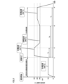
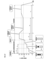
- FIG. 5 is a diagram showing a first example of the temperature transition of the heating unit 121B due to the heating control during authentication and the main heating control.
- the horizontal axis represents the period
- the vertical axis represents the temperature [° C.] of the heating section 121B.
- "R.T" on the vertical axis of FIG. 5 represents room temperature.
- the control unit 116B detects this heating start operation.
- the control unit 116B starts the authentication process from time t0, and also starts heating control during authentication with a target temperature of 100 [° C.].
- the temperature of the heating unit 121B is increased from time t0 toward 100 [°C], and after reaching 100 [°C], it is controlled to maintain the temperature at 100 [°C].
- control unit 116B ends the heating control during authentication and starts the main heating control at time t1.
- the target temperature during the main heating changes depending on the elapsed time after the main heating control is started. More specifically, as shown in FIG. 5, the target temperature during main heating when the elapsed time from the start of main heating control is from 0 [s] to Ta [s] (however, Ta>0). is assumed to be 300 [°C]. Further, when the elapsed time from the start of the main heating control is from Ta [s] to Tb [s] (however, Tb>Ta), the target temperature during the main heating is set to 240 [° C.]. Then, when the elapsed time from the start of the main heating control is from Tb [s] to Tc [s] (however, Tc>Tb), the target temperature during the main heating is set to 260 [° C.].
- the heating section 121B is first heated to 300 [°C], and after reaching 300 [°C], it is kept at 300 [°C] until time t2.
- the time t2 is a time when Ta [s] has elapsed from the time t1.
- the temperature of the heating section 121B is lowered to 240 [°C], and after reaching 240 [°C], it is controlled to maintain 240 [°C] until time t3.
- the time t3 is a time when Tb [s] has elapsed from the time t1.
- the heating section 121B is heated again toward 260 [°C], and after reaching 260 [°C], it is controlled to maintain the temperature at 260 [°C] until time t4.
- Ru is a time when Tc [s] has elapsed from the time t1.
- the control unit 116B ends the main heating control. After the main heating control ends, heat is naturally radiated from the heating section 121B, and the temperature of the heating section 121B gradually decreases toward room temperature.
- the control unit 116B controls the heating unit 121B to reach the target temperature of 100 [°C] during authentication before starting the main heating control by executing the heating control during authentication during the authentication process. Temperature can be increased. As a result, after starting the main heating control, it is only necessary to raise the temperature of the heating section 121B from 100 [°C] to 300 [°C], which is the target temperature during the first main heating. Compared to the case where the temperature is heated, the time required to reach 300[° C.] can be shortened. Therefore, after the authentication process is completed (that is, after the main heating control starts), it is possible to quickly raise the temperature of the heating section 121B to the temperature at which aerosol is generated.
- heating control during authentication is realized by the control unit 116B executing heating control based on a heating profile for heating control during authentication that defines a target temperature during authentication.
- main heating control is realized by the control unit 116B executing heating control based on a heating profile for main heating control that defines a target temperature during main heating.
- the heating control during authentication and the main heating control may be realized by the control unit 116B performing heating control based on one heating profile that defines the target temperature during authentication and the target temperature during main heating. .
- the control unit 116 may interrupt the heating control during authentication.
- a predetermined time for example, 20 [s]
- the control unit 116 may interrupt the heating control during authentication.
- the heating control during authentication may be terminated.
- deterioration of the stick-shaped base material 150 due to continued heating control during authentication for a long time can be suppressed, and it is possible to continue to use the stick-shaped base material 150 that has been heated during the current authentication process. .
- control unit 116B may set the target temperature during authentication to be lower when a predetermined time has elapsed since the start of the authentication process than before the predetermined time has elapsed.
- the target temperature during authentication may be set to 100 [° C.] until a predetermined time elapses from time t0, and the target temperature during authentication becomes 70 [° C.] after a predetermined time elapses from time t0.
- the same target temperature during authentication can be maintained even after the predetermined time has elapsed.
- the power supplied to the heating unit 121B can be reduced, and an increase in the power consumption of the suction device 100B can be suppressed.
- the target temperature during authentication is set to a single 100 [°C] and the temperature of the heating section 121B is raised and maintained at 100 [°C] by heating control during authentication, but the present invention is not limited to this. .
- the authentication process may be completed in a short time (e.g., about 5 [s]) or it may take a long time (e.g., it takes about 20 [s] to complete). )In some cases. If the target temperature during authentication is set to a single value (that is, uniform), if the authentication process becomes long, the time until aerosol is generated may also become long.
- a plurality of target temperatures during authentication may be provided, and the target temperature during authentication may become higher according to the elapsed time after the authentication process is started.
- a second example in which the target temperature during authentication is configured to increase in accordance with the elapsed time after the authentication process is started will be described below.
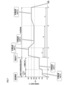
- FIG. 6 is a diagram showing a second example of temperature transition of heating unit 121B due to heating control during authentication and main heating control.
- the explanation will focus on the parts that are different from the explanation of FIG. 5, and the explanation of the parts that are common to the explanation of FIG. 5 will be omitted or simplified as appropriate.
- three target temperatures during authentication are provided: 100 [°C], 150 [°C], and 200 [°C].
- the target temperature during authentication is set to 100 [° C.].
- the target temperature during authentication when the elapsed time from the start of heating control during authentication is from Tx [s] to Ty [s] (Ty>Tx) is set to 150 [° C.].
- the target temperature during authentication is set to 200[° C.] when the elapsed time after the heating control during authentication is started is after Ty [s].
- the temperature of the heating section 121B is first raised toward 100 [°C]; After reaching the temperature, the temperature is controlled to be maintained at 100[° C.] until time t11.
- the time t11 is a time when Tx [s] has elapsed from the time t0.
- the heating section 121B is heated again toward 150 [°C], and after reaching 150 [°C], it is controlled to maintain the temperature at 150 [°C] until time t12. Ru.
- the time t12 is a time when Ty [s] has elapsed from the time t0.
- the heating section 121B is heated again toward 200 [°C], and after reaching 200 [°C], it is controlled to maintain 200 [°C] until time t1.
- the target temperature during authentication may be set to a relatively low 100 [°C], so that the temperature of the heating section 121B is raised and maintained at 100 [°C] during the authentication process, regardless of the length of the authentication process.
- the temperature of the heating section 121B is increased from 100 [°C] to 300 [°C], which is the target temperature during the first main heating (i.e., with the start of the main heating control). It is necessary to raise the temperature by 200 [°C] minutes). Therefore, in this case, as the authentication process becomes longer, the time until the aerosol is generated may also become longer.
- the target temperature during authentication is set to a relatively high 200 [°C], so that the temperature of the heating section 121B is raised and maintained at 200 [°C] during the authentication process, regardless of the length of the authentication process. It is also possible. In this case, although the time required to raise the temperature of the heating section 121B to the temperature at which aerosol is generated can be shortened by this heating control, the power supplied to the heating section 121B during the authentication process increases; This may lead to an increase in power consumption of the suction device 100B.
- the heating section 121B can be raised to a relatively high temperature during the authentication process. Compared to the case where the temperature is maintained, the power supplied to the heating unit 121B during the authentication process can be reduced, and an increase in the power consumption of the suction device 100B can be suppressed.
- the temperature of the heating section 121B is raised and maintained at a relatively high temperature during the authentication process. It is also possible to suppress deterioration of the stick-shaped base material 150 during the authentication process compared to the case where the authentication process is performed.
- the target temperature during authentication is increased according to the elapsed time after the heating control during authentication is started, but the present invention is not limited to this.
- the target temperature during authentication may be configured to increase depending on the progress of the authentication process.
- the progress of the authentication process is an evaluation value that represents the progress of the authentication process (in other words, the degree of progress), and in this embodiment, the progress of the authentication process is expressed from 0 [%] to 100 [%]. It shall be expressed as a percentage.
- the period from time t0 to time t11 shown in FIG. 6 is a period in which the progress of the authentication process is less than 33%.
- the period from time t11 to time t12 is a period in which the degree of progress of the authentication process is 33 [%] or more and less than 66 [%].
- the period from time t12 to time t1 is a period in which the degree of progress of the authentication process is 66% or more.
- the target temperature during authentication is set to 100[°C] when the progress of the authentication process is from 0[%] to 33[%], and the progress of the authentication process is from 33[%] to 66[%]. %], the target temperature during authentication is 150[°C], and when the progress of the authentication process is from 66% to 100%, the target temperature during authentication is 200[°C].
- the control unit 116B derives the degree of progress of the authentication process while the authentication process is being performed.
- the progress level of the authentication process can be derived based on, for example, the total amount of data that needs to be processed or communicated to complete the authentication process and the amount of data that has been processed or communicated up to now.
- the degree of progress of the authentication process may be derived based on inputs (for example, operations) required to complete the authentication process and inputs up to the present time. Further, when the authentication process is divided into a plurality of phases in advance, the degree of progress of the authentication process may be derived based on the current number of phases.
- the control unit 116B controls the temperature of the heating unit 121B to 100°C by heating control during authentication.
- the temperature of the heating section 121B is raised and maintained at 100 [° C.] during the period from time t0 to time t11.
- the control unit 116B controls the heating unit 121B to reach 150°C by heating control during authentication.
- the temperature of the heating section 121B is raised and maintained at 150 [° C.] during the period from time t11 to time t12.
- control unit 116B controls the heating unit 121B to reach 200°C by heating control during authentication.
- the temperature of the heating section 121B is raised and maintained at 200 [° C.] during the period from time t12 to time t1.
- the target temperature during authentication will also increase according to the elapsed time from the start of heating control during authentication. You can get the same effect as if you did this.
- multiple user authentications may be performed in the authentication process.
- the target temperature during authentication is set to be higher when at least one of the multiple user authentications is completed than when none of the user authentications is completed. good.
- the target temperature during authentication is configured to be higher when at least one of the multiple user authentications is completed than when none of the user authentications are completed. explain.
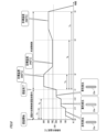
- FIG. 7 is a diagram showing a third example of temperature transition of heating unit 121B due to heating control during authentication and main heating control.
- the explanation will focus on the parts that are different from the explanation of FIG. 5, and the explanation of the parts that are common to the explanation of FIG. 5 will be omitted or simplified as appropriate.
- the authentication process sequentially executes fingerprint authentication (i.e., user authentication when the suction device 100B is closed) and communication authentication (i.e., user authentication using communication with other devices). do.
- fingerprint authentication i.e., user authentication when the suction device 100B is closed
- communication authentication i.e., user authentication using communication with other devices.
- the target temperature during authentication from the start of heating control during authentication until the completion of fingerprint authentication is set to 100 [°C]
- the target temperature during authentication after completion of fingerprint authentication is set to 150 [°C]. ].
- the heating section 121B when heating control during authentication (i.e., fingerprint authentication) is started from time t0, the heating section 121B is first heated to 100 [° C.], After reaching 100 [°C], the temperature is controlled to be maintained at 100 [°C] until time t13.
- the time t13 is the time when fingerprint authentication is completed. Then, at time t13, the heating section 121B is heated again toward 150 [°C], and after reaching 150 [°C], it is controlled to maintain 150 [°C] until time t1. Ru.
- the target temperature during authentication is higher than when any user authentication among the multiple user authentications is incomplete. It may be configured such that the rate is higher when user authentication is completed. Even with this configuration, it is possible to increase the target temperature during authentication depending on the progress of the authentication process. Therefore, the same effect can be obtained as in the case where the target temperature during authentication is increased according to the progress of the authentication processing described above.
- the control unit 116B may notify the user of information regarding the progress of the authentication process (hereinafter also referred to as "progress information") via the notification unit 113B.
- the progress information can be, for example, information indicating the degree of progress of the authentication process.
- the progress information is not limited to something that clearly indicates the progress of the authentication process, such as " ⁇ [%]", but may be something that suggests the progress of the authentication process to the extent that the user can roughly understand it. There may be.
- progress information is notified to the user by, for example, changing the color of the light emitted from the light emitting device 23a depending on the progress of the authentication process. This allows the user to be notified of the progress of the authentication process in an intuitive and easy-to-understand manner.
- FIG. 8 is a diagram showing a first example of notification of progress information.
- the explanation will focus on the parts that are different from the explanation of FIG. 6, and the explanation of the parts that are common to the explanation of FIG. 6 will be omitted or simplified as appropriate.
- the period from time t0 to time t11 is a period in which the degree of progress of the authentication process is less than 33%.
- the period from time t11 to time t12 is a period in which the degree of progress of the authentication process is 33 [%] or more and less than 66 [%].
- the period from time t12 to time t1 is a period in which the degree of progress of the authentication process is 66% or more.
- the control unit 116B when the degree of progress of the authentication process is less than 33%, the control unit 116B causes the light emitting device 23a to emit red light. Further, when the degree of progress of the authentication process is 33% or more and less than 66%, the control unit 116B causes the light emitting device 23a to emit yellow light. Then, when the degree of progress of the authentication process is 66% or more, the control unit 116B causes the light emitting device 23a to emit light in blue.
- the progress of the authentication process can be indicated to the user by the emitted light color of the light emitting device 23a. Therefore, it is possible for the user to understand the progress of the authentication process, and the convenience of the suction device 100B can be improved.
- progress information is notified to the user by changing the emitted light color of the light emitting device 23a depending on the progress of the authentication process, but the present invention is not limited to this.
- examples will be described in which the progress information is notified to the user using a method other than the color of the light emitted by the light emitting device 23a.
- FIG. 9 is a diagram showing a modification of the light emitting device 23a.
- the light emitting device 23a includes a first light emitting element 23a_1, a second light emitting element 23a_2, and a third light emitting element 23a_3.
- LEDs may be employed as the first light emitting element 23a_1, the second light emitting element 23a_2, and the third light emitting element 23a_3.
- the first light emitting element 23a_1, the second light emitting element 23a_2, and the third light emitting element 23a_3 may emit light of the same color or different colors.
- FIG. 10 is a diagram showing a second example of notification of progress information.
- the explanation will focus on the parts that are different from the explanation of FIG. 8, and the explanation of the parts that are common to the explanation of FIG. 8 will be omitted or simplified as appropriate.
- control unit 116B provides progress information to the user by varying the number of light emitting elements to emit light among the light emitting elements included in the light emitting device 23a depending on the progress of the authentication process. Notice. This allows the user to be notified of the progress of the authentication process in an intuitive and easy-to-understand manner.
- the control unit 116B controls one light emitting element (for example, the first The light emitting element 23a_1) is caused to emit light. Further, when the progress level of the authentication process is 33% or more and less than 66%, the control unit 116B controls two light-emitting elements (for example, the first light-emitting element 23a_1 and the first light-emitting element 23a_1 and The second light emitting element 23a_2) is caused to emit light.
- the control unit 116B controls three light emitting elements (i.e., the first light emitting element 23a_1, the second light emitting element 23a_2) among the light emitting elements included in the light emitting device 23a. and causes the third light emitting element 23a_3) to emit light.
- the user can determine the progress of the authentication process depending on the number of light-emitting elements that emit light. can be suggested. Therefore, it is possible for the user to understand the progress of the authentication process, and the convenience of the suction device 100B can be improved.
- control unit 116B may notify the user of progress information by changing the light emitting elements that emit light among the light emitting elements included in the light emitting device 23a depending on the progress of the authentication process.
- the control unit 116B may, for example, cause the first light emitting element 23a_1 of the light emitting elements included in the light emitting device 23a to emit light. . Further, when the progress of the authentication process is 33% or more and less than 66%, the control unit 116B causes the second light emitting element 23a_2 of the light emitting elements included in the light emitting device 23a to emit light, for example. Good too. When the degree of progress of the authentication process is 66% or more, the control unit 116B may, for example, cause the third light emitting element 23a_3 of the light emitting elements included in the light emitting device 23a to emit light.
- the progress of the authentication process can be indicated to the user by the emitted light-emitting elements. becomes possible. Therefore, it is possible for the user to understand the progress of the authentication process, and the convenience of the suction device 100B can be improved.
- the notification section 113B includes a display section that displays images
- progress information may be notified to the user by changing the display mode of this display section depending on the degree of progress of the authentication process.
- the display device 23b which is an example of the display section included in the notification section 113B.
- FIG. 11 is a diagram showing an example of the display device 23b.
- the display device 23b is provided at a position in the suction device 100B that is visible to the user.
- As the display device 23b for example, a liquid crystal display or an organic EL (Electro-Luminescence) display may be adopted.
- the display device 23b displays, for example, an indicator I as an image for notifying the user of progress information.
- Indicator I indicates the progress of the authentication process in three stages.
- FIG. 12 is a diagram showing a third example of notification of progress information.
- the explanation will focus on the parts that are different from the explanation of FIG. 8, and the explanation of the parts that are common to the explanation of FIG. 8 will be omitted or simplified as appropriate.
- the control unit 116B displays the indicator I on the display device 23b in one step. Further, when the progress of the authentication process is 33% or more and less than 66%, the control unit 116B displays the indicator I on the display device 23b in two stages. Then, when the degree of progress of the authentication process is 66% or more, the control unit 116B displays the indicator I on the display device 23b in three stages.
- the display mode of the display device 23b (the display mode of the indicator I in the example described here) depending on the progress of the authentication process
- the progress of the authentication process can be changed depending on the display mode of the display device 23b.
- the user is notified of the progress of the authentication process in three stages, but the invention is not limited to this.
- the user may be notified of the progress of the authentication process in two stages, or in multiple stages of four or more.
- the control unit 116B may notify the user of progress information (i.e., the degree of progress of the authentication process) based on the vibration mode of the vibrating device. . In that case, the number of vibrations of the vibration device or the vibration pattern may be changed depending on the progress of the authentication process.
- the control unit 116B notifies the user of progress information (i.e., the degree of progress of the authentication process) using the sound output from the sound output device. You may also do so.
- a sound output device for example, a speaker
- the progress of the authentication process is suggested to the user by notifying the user of progress information, but the present invention is not limited to this.
- the user may be notified of information indicating the elapsed time since the authentication process was started.
- the control unit 116B performs the authentication process for a certain period (hereinafter also referred to as "invalidation period") after the main heating control is completed.
- the main heating control may be configured to be executable without requiring completion. Thereby, it is possible to suppress an increase in the user's effort when chain smoking, and to suppress a decrease in the convenience of the suction device 100B.
- the length of the invalidation period is determined in advance by, for example, the manufacturer of the suction device 100.
- the time from when the main heating control is started until it is completed is assumed to be X [s] (for example, 300 [s]).
- X [s] for example, 300 [s]
- a user who performs chain smoking starts the main heating control again before 2 ⁇ X [s] have passed after the main heating control is completed. That is, if the main heating control is not restarted before 2 ⁇ X [s] has elapsed after the main heating control is completed, there is a high possibility that the user has no intention of chain smoking.
- the invalidation period may be set to twice the length of time from when the main heating control is started until it is completed, that is, the length of 2 ⁇ X [s].
- the length of the invalidation period can be set to an appropriate length, and it is possible to suppress an increase in the user's effort when chain smoking, and also to suppress a decrease in the safety and security of the suction device 100B. .
- FIG. 13 is a flowchart illustrating an example of processing executed by the control unit 116B. For example, when the suction device 100B is powered on, the control unit 116B executes a series of processes shown in FIG. 13 at a predetermined cycle.
- control unit 116B determines whether a heating start operation has been performed (step S1). If it is determined that there is no heating start operation (step S1: No), the control unit 116B repeats the process of step S1 until there is a heating start operation.
- step S2 determines whether or not it is within the invalidation period (step S2). If it is determined that it is within the invalidation period (step S2: Yes), the control unit 116B proceeds to the process of step S10, which will be described later. If it is determined that it is not within the invalidation period (step S2: No), the control unit 116B starts authentication processing (step S3) and starts heating control during authentication (step S4). Then, the control unit 116B derives the degree of progress of the authentication process and notifies the user of the progress information (step S5).
- step S6 determines whether the authentication process is completed. If it is determined that the authentication process has not been completed (step S6: No), the control unit 116B determines whether a timeout has occurred (step S7). In step S7, the control unit 116B determines that a timeout has occurred, for example, on the condition that a predetermined time has elapsed since the authentication process was started.
- step S7: No If it is determined that the timeout has not occurred (step S7: No), the control unit 116B returns to the process of step S5. If it is determined that the timeout has occurred (step S7: Yes), the control unit 116B interrupts the authentication process (step S8), ends the heating control during authentication (step S9), and performs the series of processes shown in FIG. end. In this case, the main heating control is not executed.
- Step S6 If it is determined that the authentication process has been completed (Step S6: Yes), the control unit 116B ends the heating control during authentication (Step S10) and starts the main heating control (Step S11).
- control unit 116B determines whether the main heating control is completed (step S12). If it is determined that the main heating control is not completed (step S12: No), the control unit 116B waits for the main heating control to be completed while executing the process of step S12. If it is determined that the main heating control has been completed (step S12: Yes), the control unit 116B sets an invalidation period (step S13), and ends the series of processes shown in FIG. 13.
- the temperature of the heating unit 121 is raised within a range in which no aerosol is generated from the time when the authentication process related to whether or not the suction device 100 can be used is being performed.
- the temperature of the heating unit 121 can be raised in advance during the authentication process, so that the time required to raise the temperature of the heating unit 121 to the temperature at which aerosol is generated after the authentication process is completed can be shortened. Therefore, even if it is necessary to complete the authentication process to generate aerosol, the time required to generate aerosol can be suppressed from prolonging, and the convenience due to the prolongation of the time can be improved. can suppress the decline in Therefore, while improving the safety and security of the suction device 100 by suppressing the generation of aerosol to persons other than authorized users such as children, A decrease in convenience can be suppressed, and the marketability of the suction device 100 can be improved.
- the method of controlling the suction device 100 described in the above embodiment can be realized by executing a program prepared in advance on a computer (processor).
- This program is stored in a computer-readable storage medium and executed by being read from the storage medium.
- this program may be provided in a form stored in a non-transitory storage medium such as a flash memory, or may be provided via a network such as the Internet.
- the computer that executes this program can be, for example, a computer included in the suction device 100 (for example, a CPU included in the suction device 100), but is not limited to this, and other devices that can communicate with the suction device 100 ( For example, it may be included in a smartphone or a server device).
- a suction device (suction device 100, 100A, 100B) that generates an aerosol from a base material having an aerosol source (flavor imparting cartridge 130, stick type base material 150), a heating unit (heating unit 121B) that heats the base material to generate the aerosol;
- a control unit (control unit 116, 116A, 116B) that controls the operation of the suction device; Equipped with The control unit includes: a first heating control that controls the temperature of the heating section with a target temperature lower than the lowest temperature at which the aerosol is generated; A second heating control that controls the temperature of the heating section with a temperature higher than the minimum temperature as a target temperature, Executing the first heating control when an authentication process related to whether or not the suction device can be used is being performed; When the authentication process is completed, the first heating control is ended and the second heating control is executed.
- Suction device Suction device.
- the temperature of the heating unit is raised within a range in which no aerosol is generated from the time when the authentication process related to whether or not the suction device can be used is being performed.
- the temperature of the heating section can be raised in advance during the authentication process, so that the time required to raise the temperature of the heating section to the temperature at which aerosol is generated after the authentication process is completed can be shortened. Therefore, even if the completion of the authentication process is required to execute the second heating control to generate aerosol, the time required to generate the aerosol can be suppressed and the time can be extended. It is possible to suppress the decrease in convenience caused by doing so.
- the suction device according to (1) The target temperature in the first heating control is higher than room temperature. Suction device.
- the first heating control makes it possible to raise the temperature of the heating section to a temperature higher than room temperature within a range in which aerosols are not generated.
- the authentication process becomes longer by increasing the target temperature in the first heating control according to the elapsed time after the authentication process starts, the This makes it possible to keep the temperature of the heating section higher. This makes it possible to shorten the time required to raise the temperature of the heating section to a temperature at which aerosol is generated by the second heating control executed after the authentication process is completed. Therefore, even if the authentication process takes a long time, it is possible to suppress the time required until the aerosol is generated from elongating, and to suppress a decrease in convenience due to the prolongation of the time.
- the temperature of the heating part during the authentication process will increase accordingly. It becomes possible to keep it higher. This makes it possible to shorten the time required to raise the temperature of the heating section to a temperature at which aerosol is generated by the second heating control executed after the authentication process is completed. Therefore, even if the authentication process takes a long time, it is possible to suppress the time required until the aerosol is generated from elongating, and to suppress a decrease in convenience due to the prolongation of the time.
- the target temperature in the first heating control is higher when at least one of the multiple authentications performed in the authentication process is completed than when none of the authentications is completed. By doing so, it becomes possible to increase the target temperature in the first heating control according to the progress of the authentication process.
- the suction device according to any one of (1) to (5), The control unit notifies the user of information regarding the progress of the authentication process via a notification unit (notification unit 113, 113A, 113B) that can notify predetermined information. Suction device.
- a notification unit notification unit 113, 113A, 113B
- the suction device includes a light emitting section (light emitting device 23a) that emits light
- the control unit notifies the user of information regarding the progress level by changing the light emission mode of the light emitting unit depending on the progress level. Suction device.
- the progress of the authentication process can be notified to the user in an intuitive and easy-to-understand manner.
- the suction device according to (7),
- the light emitting unit is configured to be able to emit light in a plurality of colors
- the control unit changes the color of the light emitted from the light emitting unit depending on the degree of progress. Suction device.
- the progress of the authentication process can be notified to the user in an intuitive and easy-to-understand manner.
- the suction device is configured by a plurality of light emitting elements (first light emitting element 23a_1, second light emitting element 23a_2, third light emitting element 23a_3),
- the control unit changes the light emitting element to emit light or the number of the light emitting elements to emit light among the plurality of light emitting elements according to the progress level. Suction device.
- the progress of the authentication process can be notified to the user in an intuitive and easy-to-understand manner.
- the suction device includes a display unit (display device 23b) that displays an image
- the control unit notifies the user of information regarding the degree of progress by changing the display mode of the display unit depending on the degree of progress. Suction device.
- the progress of the authentication process can be notified to the user in an intuitive and easy-to-understand manner.
- the control unit When the second heating control is executed, the control unit is configured to be able to execute the second heating control for a certain period of time after the second heating control is completed without requiring completion of the authentication process. be done, Suction device.
- the suction device according to (11), The certain period of time is twice the length of time from when the second heating control is started until it is completed. Suction device.
- the length of the certain period during which the second heating control can be executed without requiring completion of the authentication process can be set to an appropriate length.
- the suction device according to any one of (1) to (12), The control unit terminates the first heating control and does not execute the second heating control if the authentication process is interrupted without being completed. Suction device.
- Suction that includes a heating unit (heating unit 121B) that heats a base material having an aerosol source (flavor imparting cartridge 130, stick type base material 150), and generates an aerosol by heating the base material with the heating unit
- a computer control unit 116, 116A, 116B that controls the operation of the device (suction device 100, 100A, 100B)
- first heating control is performed to control the temperature of the heating section with a target temperature lower than the lowest temperature at which the aerosol is generated.
- the first heating control is ended, and a second heating control is executed to control the temperature of the heating section with a temperature higher than the minimum temperature as a target temperature. Control method for processing.
- the temperature of the heating unit is raised within a range in which no aerosol is generated from the time when the authentication process related to whether or not the suction device can be used is being performed.
- the temperature of the heating section can be raised in advance during the authentication process, so that the time required to raise the temperature of the heating section to the temperature at which aerosol is generated after the authentication process is completed can be shortened. Therefore, even if the completion of the authentication process is required to execute the second heating control to generate aerosol, the time required to generate the aerosol can be suppressed and the time can be extended. It is possible to suppress the decrease in convenience caused by doing so.
- Suction that includes a heating unit (heating unit 121B) that heats a base material having an aerosol source (flavor imparting cartridge 130, stick type base material 150), and generates an aerosol by heating the base material with the heating unit
- a computer control unit 116, 116A, 116B that controls the operation of the device (suction device 100, 100A, 100B)
- first heating control is performed to control the temperature of the heating section with a target temperature lower than the lowest temperature at which the aerosol is generated.
- the first heating control is ended, and a second heating control is executed to control the temperature of the heating section with a temperature higher than the minimum temperature as a target temperature.
- a program that performs processing.
- the temperature of the heating unit is raised within a range in which no aerosol is generated from the time when the authentication process related to whether or not the suction device can be used is being performed.
- the temperature of the heating section can be raised in advance during the authentication process, so that the time required to raise the temperature of the heating section to the temperature at which aerosol is generated after the authentication process is completed can be shortened. Therefore, even if the completion of the authentication process is required to execute the second heating control to generate aerosol, the time required to generate the aerosol can be suppressed and the time can be extended. It is possible to suppress the decrease in convenience caused by doing so.
Landscapes
- Medicinal Preparation (AREA)
Abstract
La présente invention concerne un dispositif d'inhalation (100B) qui comprend une unité de chauffage (121B) pour chauffer un matériau de base de type bâton (150) ayant une source d'aérosol et générer ainsi un aérosol, ainsi qu'une unité de commande (116B) pour commander le fonctionnement du dispositif d'inhalation (100B). L'unité de commande (116B) est conçue de façon à exécuter une commande de chauffage d'authentification pour commander la température de l'unité de chauffage (121B) avec une température cible, qui est inférieure à la température la plus basse à laquelle un aérosol est généré, et une commande de chauffage principale pour commander la température de l'unité de chauffage (121B) avec une température cible, qui est supérieure à la température la plus basse à laquelle un aérosol est généré. La commande de chauffage d'authentification est exécutée lorsqu'un processus d'authentification relatif à la possibilité d'utilisation du dispositif d'inhalation (100B) est réalisé et, lorsque le processus d'authentification est achevé, la commande de chauffage d'authentification est arrêtée et la commande de chauffage principale est exécutée.
Priority Applications (1)
| Application Number | Priority Date | Filing Date | Title |
|---|---|---|---|
| PCT/JP2022/031132 WO2024038528A1 (fr) | 2022-08-17 | 2022-08-17 | Dispositif d'inhalation, procédé de commande et programme |
Applications Claiming Priority (1)
| Application Number | Priority Date | Filing Date | Title |
|---|---|---|---|
| PCT/JP2022/031132 WO2024038528A1 (fr) | 2022-08-17 | 2022-08-17 | Dispositif d'inhalation, procédé de commande et programme |
Publications (1)
| Publication Number | Publication Date |
|---|---|
| WO2024038528A1 true WO2024038528A1 (fr) | 2024-02-22 |
Family
ID=89941533
Family Applications (1)
| Application Number | Title | Priority Date | Filing Date |
|---|---|---|---|
| PCT/JP2022/031132 WO2024038528A1 (fr) | 2022-08-17 | 2022-08-17 | Dispositif d'inhalation, procédé de commande et programme |
Country Status (1)
| Country | Link |
|---|---|
| WO (1) | WO2024038528A1 (fr) |
Citations (3)
| Publication number | Priority date | Publication date | Assignee | Title |
|---|---|---|---|---|
| JP2020513851A (ja) * | 2017-03-15 | 2020-05-21 | キャノピー グロウス コーポレイション | 改善されたパーソナル気化装置用のシステム及び方法 |
| JP2020195347A (ja) * | 2019-06-04 | 2020-12-10 | Smk株式会社 | 煙霧質発生装置および煙霧質発生方法 |
| WO2021260897A1 (fr) * | 2020-06-25 | 2021-12-30 | 日本たばこ産業株式会社 | Dispositif d'inhalation, procédé de commande et programme |
-
2022
- 2022-08-17 WO PCT/JP2022/031132 patent/WO2024038528A1/fr unknown
Patent Citations (3)
| Publication number | Priority date | Publication date | Assignee | Title |
|---|---|---|---|---|
| JP2020513851A (ja) * | 2017-03-15 | 2020-05-21 | キャノピー グロウス コーポレイション | 改善されたパーソナル気化装置用のシステム及び方法 |
| JP2020195347A (ja) * | 2019-06-04 | 2020-12-10 | Smk株式会社 | 煙霧質発生装置および煙霧質発生方法 |
| WO2021260897A1 (fr) * | 2020-06-25 | 2021-12-30 | 日本たばこ産業株式会社 | Dispositif d'inhalation, procédé de commande et programme |
Similar Documents
| Publication | Publication Date | Title |
|---|---|---|
| KR102636854B1 (ko) | 전자 에어로졸 제공 시스템을 위한 제어 디바이스 | |
| JP7253121B2 (ja) | 吸引装置、方法、及びプログラム | |
| WO2021260894A1 (fr) | Dispositif d'inhalation, procédé de commande et programme | |
| WO2024038528A1 (fr) | Dispositif d'inhalation, procédé de commande et programme | |
| WO2021240617A1 (fr) | Dispositif d'inhalation, procédé de commande et programme | |
| US20230000152A1 (en) | Inhaling device, control method, and non-transitory computer readable medium | |
| US20230114675A1 (en) | Display device, inhaler device, display method, and program | |
| WO2024038529A1 (fr) | Dispositif d'inhalation, procédé de commande et programme | |
| WO2022230433A1 (fr) | Unité d'alimentation pour inhalateur | |
| WO2024038531A1 (fr) | Dispositif d'inhalation, procédé de commande et programme | |
| JP7359957B2 (ja) | 吸引装置、情報処理装置、及び制御方法 | |
| WO2024038530A1 (fr) | Dispositif d'inhalation, procédé de commande et programme | |
| WO2024047705A1 (fr) | Dispositif d'inhalation, matériau de base et système d'inhalation | |
| EP4074200A1 (fr) | Dispositif d'inhalation, procédé de commande et programme | |
| WO2022079897A1 (fr) | Dispositif d'inhalation, procédé, et programme | |
| WO2024095455A1 (fr) | Dispositif de traitement d'informations, système d'inhalation et procédé de présentation d'informations | |
| WO2023100228A1 (fr) | Dispositif d'aspiration | |
| WO2022190211A1 (fr) | Dispositif d'inhalation et programme | |
| WO2023112149A1 (fr) | Dispositif de traitement d'informations, procédé de traitement d'informations et programme | |
| WO2022219673A1 (fr) | Dispositif de commande, procédé de commande et programme | |
| WO2023157276A1 (fr) | Système de chauffage par induction, procédé de commande et programme | |
| WO2023157275A1 (fr) | Système de chauffage par induction, procédé de commande et programme | |
| JP7492562B2 (ja) | 吸引器用の電源ユニット | |
| WO2023170958A1 (fr) | Système de génération d'aérosol, procédé de commande et programme | |
| WO2023021567A1 (fr) | Dispositif d'inhalation |
Legal Events
| Date | Code | Title | Description |
|---|---|---|---|
| 121 | Ep: the epo has been informed by wipo that ep was designated in this application |
Ref document number: 22955702 Country of ref document: EP Kind code of ref document: A1 |