WO2024034409A1 - 送信装置及び送信方法、受信装置及び受信方法 - Google Patents
送信装置及び送信方法、受信装置及び受信方法 Download PDFInfo
- Publication number
- WO2024034409A1 WO2024034409A1 PCT/JP2023/027477 JP2023027477W WO2024034409A1 WO 2024034409 A1 WO2024034409 A1 WO 2024034409A1 JP 2023027477 W JP2023027477 W JP 2023027477W WO 2024034409 A1 WO2024034409 A1 WO 2024034409A1
- Authority
- WO
- WIPO (PCT)
- Prior art keywords
- circuit
- output
- sampling points
- ofdm
- symbol
- Prior art date
- Legal status (The legal status is an assumption and is not a legal conclusion. Google has not performed a legal analysis and makes no representation as to the accuracy of the status listed.)
- Ceased
Links
Images





Classifications
-
- H—ELECTRICITY
- H04—ELECTRIC COMMUNICATION TECHNIQUE
- H04L—TRANSMISSION OF DIGITAL INFORMATION, e.g. TELEGRAPHIC COMMUNICATION
- H04L27/00—Modulated-carrier systems
- H04L27/26—Systems using multi-frequency codes
-
- H—ELECTRICITY
- H04—ELECTRIC COMMUNICATION TECHNIQUE
- H04B—TRANSMISSION
- H04B1/00—Details of transmission systems, not covered by a single one of groups H04B3/00 - H04B13/00; Details of transmission systems not characterised by the medium used for transmission
- H04B1/02—Transmitters
- H04B1/04—Circuits
-
- H—ELECTRICITY
- H04—ELECTRIC COMMUNICATION TECHNIQUE
- H04L—TRANSMISSION OF DIGITAL INFORMATION, e.g. TELEGRAPHIC COMMUNICATION
- H04L27/00—Modulated-carrier systems
- H04L27/26—Systems using multi-frequency codes
- H04L27/2601—Multicarrier modulation systems
- H04L27/2602—Signal structure
- H04L27/2605—Symbol extensions, e.g. Zero Tail, Unique Word [UW]
- H04L27/2607—Cyclic extensions
-
- H—ELECTRICITY
- H04—ELECTRIC COMMUNICATION TECHNIQUE
- H04L—TRANSMISSION OF DIGITAL INFORMATION, e.g. TELEGRAPHIC COMMUNICATION
- H04L27/00—Modulated-carrier systems
- H04L27/26—Systems using multi-frequency codes
- H04L27/2601—Multicarrier modulation systems
- H04L27/2626—Arrangements specific to the transmitter only
- H04L27/2627—Modulators
- H04L27/2634—Inverse fast Fourier transform [IFFT] or inverse discrete Fourier transform [IDFT] modulators in combination with other circuits for modulation
- H04L27/2636—Inverse fast Fourier transform [IFFT] or inverse discrete Fourier transform [IDFT] modulators in combination with other circuits for modulation with FFT or DFT modulators, e.g. standard single-carrier frequency-division multiple access [SC-FDMA] transmitter or DFT spread orthogonal frequency division multiplexing [DFT-SOFDM]
Definitions
- the present invention relates to a transmitting device, a transmitting method, a receiving device, and a receiving method that can be used in a next-generation mobile communication system.
- OFDM Orthogonal Frequency Division Multiplexing
- wireless LAN Local Area Network
- 4G 4th Generation
- 5G 5th Generation
- the OFDM system is a multicarrier system that simultaneously transmits multiple subcarriers, and complex information symbols of multiple subcarriers arranged in the frequency direction are processed by IFFT (Inverse fast Fourier transform) or IDFT (Inverse discrete Fourier transform). transform: inverse discrete Fourier transform) to generate the time waveform of the transmitted signal.
- IFFT Inverse fast Fourier transform
- IDFT Inverse discrete Fourier transform
- the CP-OFDM method is known as one of the technologies based on the OFDM method.
- a plurality of OFDM symbols in which a temporally redundant section called a guard interval (CP (Cyclic Prefix)) is added to a time waveform are concatenated and transmitted.
- CP Cyclic Prefix
- ICI inter-carrier interference
- each subcarrier On the receiving side, multiple concatenated OFDM symbols are processed one by one. By removing the guard interval from each OFDM symbol and performing FFT (fast Fourier transform) or DFT (discrete Fourier transform) on the remaining signal section, complex information symbols of each subcarrier signal in the frequency domain can be obtained. restore.
- FFT fast Fourier transform
- DFT discrete Fourier transform
- Non-Patent Document 1 a zero padding (ZP-) OFDM method is described in Non-Patent Document 1 as a method that uses truncation of symbol ends. This method inserts zero data into the CP interval.
- the present invention improves time efficiency and transmission speed by truncating a part of the OFDM symbol and concatenating multiple OFDM symbols without leaving a guard interval. The aim is to improve the
- an object of the present invention is to provide a transmitting device, a transmitting method, a receiving device, and a receiving method that can further improve the transmission efficiency of the OFDM system.
- the present invention provides a transmitter using orthogonal frequency division multiplexing, a redundant signal adding circuit that adds redundant signals of a predetermined number of sampling points to a plurality of sampling points of the output of the IFFT circuit or the IDFT circuit; a sampling point truncation circuit that cuts off a predetermined number of sampling points from each of the front end and rear end of the output of the redundant signal addition circuit;
- This is a transmitting device configured to transmit symbols output from a sampling point truncation circuit.
- the present invention also provides a transmission method using orthogonal frequency division multiplexing, By redundant signal addition processing, redundant signals of a predetermined number of sampling points are added to the plurality of sampling points of the output of the IFFT circuit or IDFT circuit, By sampling point truncation processing, a predetermined number of sampling points are cut off from each of the leading and trailing ends of the symbol to which the redundant signal is added, This is a transmission method that transmits symbols whose sampling points are truncated.
- the present invention provides an orthogonal frequency division multiplexing receiving apparatus that includes: a zero insertion circuit that inserts into the received symbol a number of zero sampling points equal to the number truncated at the transmitting side; a redundant signal removal circuit that removes a redundant signal from the output of the zero insertion circuit;
- This receiving device includes a Fourier transform circuit that performs Fourier transform on the output of a redundant signal removal circuit.
- the present invention provides a receiving method for orthogonal frequency division multiplexing, including: A zero insertion process inserts into the received symbol a number of zero sampling points equal to the number truncated at the transmitter, Redundant signal removal processing removes redundant signals from symbols in which zero sampling points have been inserted, This is a reception method in which an FFT or DFT circuit performs FFT or DFT on an output from which redundant signals have been removed.
- the present invention is compatible with the conventional OFDM method and can improve throughput.
- the effects described here are not necessarily limited, and may be any effect described in this invention. Further, the contents of the present invention are not to be interpreted as being limited by the effects illustrated in the following description.
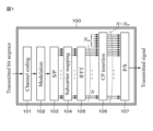
- FIG. 1 is a block diagram showing the configuration of a CP-OFDM transmitter.
- FIG. 2 is a block diagram showing the configuration of a CP-OFDM receiver.
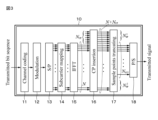
- FIG. 3 is a block diagram showing the configuration of a transmitter according to an embodiment of the present invention.
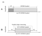
- 4A and 4B are schematic diagrams for explaining the symbol structure of the CP-OFDM system and the symbol structure of an embodiment of the present invention.
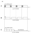
- 5A, 5B, and 5C are timing charts used to explain the CP-OFDM method, the ZP-OFDM method, and an embodiment of the present invention.
- FIG. 6 is a block diagram showing the configuration of a receiver according to an embodiment of the present invention.
- FIG. 7 is a graph for evaluating the bit error rate.
- FIG. 1 is a block diagram showing the configuration of a CP-OFDM transmitter.
- FIG. 2 is a block diagram showing the configuration of a CP-OFDM receiver.
- FIG. 3 is a block diagram showing
- FIG. 8 is a graph for evaluating the bit error rate.
- FIG. 9 is a graph for evaluating the bit error rate.
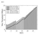
- FIG. 10 is a graph showing the maximum throughput achievable by the present invention for each MCS.
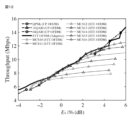
- FIG. 11 is a graph for evaluating throughput characteristics when the optimal MCS and N SP can be adaptively selected.
- FIG. 12 is a graph for evaluating throughput characteristics when the optimal MCS and N SP can be adaptively selected.
- FIG. 13 is a graph for evaluating throughput characteristics when the optimal MCS and N SP can be adaptively selected.
- FIG. 1 shows the configuration of a CP-OFDM transmitter 100.
- a transmission signal is supplied to a channel encoding circuit 101, and channel encoding processing is performed.
- the output sequence of channel encoding circuit 101 is modulated by modulation circuit 102 to obtain complex symbols.
- the obtained complex symbols are parallelized by the serial-to-parallel conversion circuit 103.
- the output signal of the serial-to-parallel conversion circuit 103 is mapped in the frequency domain together with a reference signal in a subcarrier mapping circuit 104.
- An IFFT circuit 105 subjects the output of the subcarrier mapping circuit 104 to IFFT or IDFT.
- N sampling points output from the IFFT circuit 105 are supplied to a CP insertion circuit 106, a CP (Cyclic Prefix) as a redundant signal is inserted, and a CP-OFDM symbol is generated at the output of the CP insertion circuit 106.
- the number of sampling points of CP is N CP .
- the CP-OFDM symbol is serialized by the parallel-to-serial conversion circuit 107 and sent to the transmission path. For example, data for a certain period of time from the rear end of the OFDM symbol is inserted at the beginning of the OFDM symbol as a cyclic prefix.
- Equation 1 The m-th CP-OFDM symbol shown by Equation 1 is expressed as shown in Equation 2 (Equation (1)).
- N is the number of subcarriers.
- Equation 2 Equation (1)
- x m is a modulation subcarrier symbol expressed on the frequency axis and is expressed as Equation 3
- Equation 4 the inverse discrete Fourier transform matrix
- Equation 6 is the number of time samples corresponding to CP.
- Equation 8 in Equation 7 is a matrix with i rows and j columns in which all elements are 0, and I N is a unit matrix with N rows and N columns.
- FIG. 2 shows the configuration of a CP-OFDM receiver 200.
- the received signal is supplied to a serial/parallel conversion circuit 201 and converted into a parallel signal.
- the output of the serial-to-parallel conversion circuit 201 (the number of sampling points is N+N CP ) is supplied to the CP removal circuit 202 to remove CP.
- the received signal from which the CP has been removed is supplied to an FFT circuit 203 to perform FFT or DFT to obtain complex symbols mapped in the frequency domain.
- the received symbol string is expressed by equation 9 (formula (2))
- Equation 10 The CP removal matrix in Equation 9 is expressed as Equation 10.
- the DFT matrix is expressed as Equation 11, and its elements are expressed as Equation 12.
- the output signal of the FFT circuit 203 is supplied to a parallel-to-serial conversion circuit 204 and serialized.
- the output signal of parallel-to-serial conversion circuit 204 is supplied to channel estimation and channel equalization circuit 205 .
- the output signal of the channel estimation and channel equalization circuit 205 is supplied to a subcarrier demapping circuit 206, and the output of the subcarrier demapping circuit 206 is supplied to a demodulation circuit 207.
- the output of the demodulation circuit 207 is supplied to a channel decoding circuit 208, where, for example, an LDPC code is decoded to obtain a received sequence.
- the method of the present invention is called the STT (Symbol-edges Truncating Transmission)-OFDM method.
- STT Symbol-edges Truncating Transmission
- the time efficiency of conventional OFDM can be improved by transmitting only part of the CP-OFDM symbols.
- normal OFDM demodulation processing is performed after interpolating 0 to the untransmitted portion.
- Inter-carrier interference occurs when using the STT-OFDM method.
- a powerful error correction code such as an LDPC code
- communication quality can be maintained even if some symbols are lost. Therefore, the STT-OFDM method can be expected to reduce the transmission energy per symbol compared to the CP-OFDM method.
- FIG. 3 shows the configuration of a transmitter 10 according to an embodiment of the present invention. Similar to the CP-OFDM method described above, CP-OFDM symbols are generated. That is, the transmission signal is supplied to the channel encoding circuit 11, and the output sequence of the channel encoding circuit 11 is modulated by the modulation circuit 12 to obtain complex symbols. Next, the complex symbols are parallelized by the serial-to-parallel conversion circuit 13. The output signal of the serial-to-parallel conversion circuit 13 is mapped in the frequency domain together with a reference signal by a subcarrier mapping circuit 14.
- the output of the subcarrier mapping circuit 14 is subjected to IFFT or IDFT by an IFFT circuit 15.
- the output of the IFFT circuit 15 is supplied to the CP insertion circuit 16, a CP is inserted, and a CP-OFDM symbol with the number of sampling points of N+N CP is generated at the output of the CP insertion circuit 16.
- This CP-OFDM symbol is expressed by the above-mentioned equation 2 (formula (1)).
- the CP-OFDM symbol output from the CP insertion circuit 16 is supplied to the sampling point truncation circuit 17.
- the sampling point truncation circuit 17 truncates an arbitrary number of symbol points (time sampling points) at the beginning and end of the CP-OFDM symbol.
- the STT-OFDM symbol output from the sampling point truncation circuit 17 is concatenated with serial data in the parallel-to-serial conversion circuit 18 and sent to the transmission path.
- FIG. 4A shows the CP-OFDM symbol obtained at the output of the CP insertion circuit 16.
- a CP-OFDM symbol is an OFDM symbol with CP added in front.
- the sampling point truncation circuit 17 cuts off an arbitrary number of sampling points before and after the CP-OFDM symbol to form an STT-OFDM symbol, as shown in FIG. 4B.
- Equation 14 The m-th STT-OFDM symbol shown in Equation 13 is expressed as Equation 14 (Equation (3)). Further, in Equation 14 (Equation (3)), s(m, n) is the n-th sampling point of the m-th STT-OFDM symbol.
- the number of sampling points to be discarded by the sampling point truncation circuit 17 is expressed by Equation 15, and the number of sampling points to be discarded is expressed by Equation 16.
- the number of sampling points to be discarded is arbitrary and may be shorter or longer than the CP (guard interval section). Furthermore, it is not necessary that the number of sampling points to be rounded down be equal in the preceding and succeeding sections.
- Equation 18 indicates the same signal waveform as the CP-OFDM symbol.
- FIG. 5A shows a transmission signal in which four symbols are concatenated using a CP-OFDM symbol as an example.
- FIG. 5B shows a transmission signal concatenated with four symbols as an example of the zero padding (ZP-) OFDM method, which is known as one of the methods using truncation of symbol ends.
- ZP- zero padding
- FIG. 5C a predetermined number (four in the illustrated example) of generated STT-OFDM symbols are concatenated without gaps.
- the truncated section is left as a guard interval (GI)
- STT-OFDM symbols are concatenated without leaving it as a guard interval (GI).
- An embodiment of the present invention can reduce transmission time compared to the CP-OFDM method and the ZP-OFDM method. Note that in the present invention, the guard interval section may not be completely deleted, but a section with a length that can improve throughput may be left.
- FIG. 6 shows an example of the configuration of the receiver 20 in an embodiment of the present invention.
- This figure shows a receiver configuration for sequentially cutting out STT-OFDM symbols one by one from the beginning of a received signal in which multiple STT-OFDM symbols are concatenated, and demodulating that one STT-OFDM symbol.
- One STT-OFDM symbol cut out from the received signal is supplied to the serial-to-parallel conversion circuit 21, where it is converted into a parallel signal with N STT sampling points.
- the output of the serial-to-parallel conversion circuit 21 is supplied to a zero insertion circuit 22, and zeros are inserted into the sections before and after the truncated section on the transmitting side.
- the zero insertion circuit 22 inserts zeros so that the number of sampling points of one OFDM symbol is N+N CP .
- the output of the zero insertion circuit 22 is supplied to the CP removal circuit 23, and the CP (guard interval section) is removed.
- the received signal from which the CP has been removed is supplied to the FFT circuit 24 to perform FFT or DFT to obtain complex symbols mapped in the frequency domain.
- the output signal of the FFT circuit 24 is supplied to a parallel-to-serial conversion circuit 25 and serialized.
- the output signal of the parallel-to-serial conversion circuit 25 is supplied to a channel estimation and channel equalization circuit 26.
- the output signal of the channel estimation and channel equalization circuit 26 is supplied to a subcarrier demapping circuit 27, and the output of the subcarrier demapping circuit 27 is supplied to a demodulation circuit 28.
- the output of the demodulation circuit 28 is supplied to a channel decoding circuit 29, where, for example, an LDPC code is decoded to obtain a received sequence.
- Equation 19 Equation (4)
- Equation 19 Equation (4)
- Equation 20 represents zero-mean complex Gaussian noise.
- the zero insertion circuit 22 performs zero interpolation on the received signal by adding a number of zeros equal to the number of sampling points cut off on the transmitting side to the end of the STT-OFDM symbol. As a result, a received signal expressed by equation 22 is obtained. This received signal is expressed by equation 23 (formula (5)).
- Equation 24 Equation (6)
- a received sequence is obtained by performing channel equalization and channel estimation, demodulating, and then decoding the LDPC code.
- the logarithmic domain Sum-Product decoding method is generally used to decode the LDPC code.
- This decoding method uses a log likelihood ratio (LLR). Since the absolute value of LLR is inversely proportional to the magnitude of noise power, the absolute value of LLR takes a very large value in a high SNR environment. However, if a part of the transmitted signal is truncated and transmitted on the transmitting side, the orthogonality of OFDM is destroyed and ICI occurs, so in a high SNR environment, an LLR with a very large absolute value for the wrong sign is calculated. There may be cases. Therefore, deterioration in communication quality is suppressed by performing LLR adjustment on the output of the demodulation circuit 28.
- LLR log likelihood ratio
- a link level simulation of a 5G system is performed when the CP-OFDM system is replaced with the STT-OFDM system.
- Table 1 shows the parameter specifications of the link level simulator.
- Equation 25 the number of sampling points to be truncated at the front end and the rear end is made equal.
- FIGS. 7, 8, and 9 show BLER with respect to changes in Es/No, and express the BLER characteristics as a function of N SP .
- N SP 0 means CP-OFDM system. The smaller the value of Es/No, the more noise there is.
- FIG. 7 shows the BLER characteristics of (MCS7 QPSK, 526/1024)
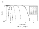
- FIG. 8 shows the BLER characteristics of MCS13 (16QAM, 490/1024)
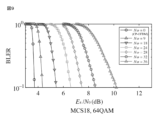
- FIG. 9 shows the BLER characteristics of MCS18 (64QAM, 466/1024). Show characteristics.
- MCS Modulation and Coding Scheme
- MCS Modulation and Coding Scheme
- the MCS changes from a low value to a high value in order of QPSK, 16QAM, and 64QAM.
- the modulation method for MCS1 to MCS9 is QPSK
- the modulation method for MCS10 to MCS16 is 16QAM
- the modulation method for MCS17 and above is 64QAM.
- the size of N SP is smaller than QPSK. This is because, unlike QPSK, 16QAM has information in the amplitude, so even if the influence of ICI is suppressed with the LDPC code, the remaining interference component has a large influence on demodulation of 16QAM.
- the size of N SP is smaller than that of QPSK and 16QAM.
- Equation 26 Equation (7)
- T CP 71.4 ⁇ s is the symbol time of 1 CP-OFDM symbol
- m is the modulation level number
- Nsub is the number of subcarriers of 1 OFDM symbol
- R is the coding rate.
- Equation 27 Equation (8)
- N represents the number of sampling points of one OFDM symbol.
- the modulation method for MCS1 to MCS9 is QPSK
- the modulation method for MCS10 to MCS16 is 16QAM
- the modulation method for MCS17 and above is 64QAM.
- the amount of increase in throughput for the CP-OFDM scheme decreases as the MCS increases.
- FIG. 11 shows the throughput characteristics (QPSK region) of the STT-OFDM system when the optimal MCS and N SP can be adaptively selected.
- FIG. 12 shows the throughput characteristics (16QAM region) of the STT-OFDM system when the optimal MCS and N SP can be adaptively selected.
- FIG. 13 shows the throughput characteristics (64QAM region) of the STT-OFDM system when the optimal MCS and N SP can be adaptively selected.
- the STT-OFDM method achieved higher throughput than the CP-OFDM method in all MCSs.
- FIG. 13 it was found that the throughput of the STT-OFDM method using 64QAM was lower than that of the CP-OFDM method.
- the present invention can improve the throughput by approximately 1.5 times compared to the CP-OFDM method in a low SNR environment, and can contribute to expanding the coverage of next-generation systems. be. Further, by adaptively switching the MCS according to the SNR (Es/No), throughput can be favorably improved.
- the transmission energy per symbol can be reduced.
- areas with low SNR IoT communication systems that cover wide areas, reception near the cell edge, reception when the transmission distance is long distance, reception when the transmission power is low in power-saving wireless systems, etc., on the sea and in the air
- transmission efficiency can be improved by up to 1.5 times.
- the embodiment of the present invention described above has many signal processing parts common to the conventional CP-OFDM transmitter and receiver, and has the advantage of excellent compatibility.
- the present invention is not limited to the embodiments described above, and various modifications based on the technical idea of the present invention are possible. For example, by taking advantage of their excellent compatibility, it is possible to have a configuration in which both the STT-OFDM system and the CP-OFDM system can be switched. Furthermore, the functions of the components of the transmitting device and receiving device in the embodiments described above can be realized by executing software processing.
- DESCRIPTION OF SYMBOLS 10 ... Transmitter, 11... Channel encoding circuit, 12... Modulation circuit 14... Subcarrier mapping circuit, 15... IFFT circuit 16... CP insertion circuit, 17... Sampling Point truncation circuit 18...Parallel-serial conversion circuit, 20...Receiver, 21...Parallel-serial conversion circuit 22...Zero insertion circuit, 23...CP removal circuit, 24...FFT circuit 27 ... Subcarrier demapping circuit, 29... Channel decoding circuit
Landscapes
- Engineering & Computer Science (AREA)
- Computer Networks & Wireless Communication (AREA)
- Signal Processing (AREA)
- Physics & Mathematics (AREA)
- Discrete Mathematics (AREA)
- General Physics & Mathematics (AREA)
- Mathematical Physics (AREA)
- Digital Transmission Methods That Use Modulated Carrier Waves (AREA)
Abstract
従来の方式と互換性を有し、伝送効率を向上することができる送信装置を提供する。直交周波数分割多重方式の送信装置において、IFFT回路もしくはIDFT回路の出力の複数のサンプリング点に対して所定数のサンプリング点の冗長信号を付加する冗長信号付加回路と、冗長信号付加回路の出力の前端及び後端のそれぞれから所定数のサンプリング点を切り捨てるサンプリング点切り捨て回路とを備え、サンプリング点切り捨て回路の出力シンボルを伝送するようにした送信装置である。
Description
本発明は、次世代移動通信システムにおいて使用することが可能な送信装置及び送信方法、受信装置及び受信方法に関する。
OFDM(Orthogonal Frequency Division Multiplexing:直交周波数分割多重)方式は、現在の通信方式の主流として、無線LAN(Local Area Network) 、4G(4th Generation:第4世代移動通信システム)、5G(5th Generation:第5世代移動通信システム)地上デジタル放送など、様々なシステムで採用されている。OFDM方式では、複数のサブキャリアを同時に伝送するマルチキャリア方式であり、周波数方向に並べた複数のサブキャリアの複素情報シンボルをIFFT(Inverse fast Fourier transform:逆高速フーリエ変換)もしくはIDFT(Inverse discrete Fourier transform:逆離散フーリエ変換)することで、その送信信号の時間波形を生成する。
OFDM方式をベースとした技術の一つとして、CP-OFDM方式が知られている。CP-OFDM方式においては、時間波形にガードインターバル(CP(Cyclic Prefix):サイクリックプレフィクス)と呼ばれる時間的冗長区間を追加したOFDMシンボルを複数連結して送信する。CP-OFDM方式では、OFDMシンボルの後端からの一定時間分のデータをCPとしてOFDMシンボルの先頭に挿入することで、キャリア間干渉(ICI:Inter-Carrier Interference)を抑制できる。
受信側では、複数連結されたOFDMシンボルを一つずつ処理する。各OFDMシンボルからガードインターバルを取り除き、残った信号区間をFFT(fast Fourier transform:高速フーリエ変換)もしくはDFT(discrete Fourier transform:離散フーリエ変換)することで、周波数領域の各サブキャリア信号の複素情報シンボルを復元する。送信側でIFFTもしくはIDFT、受信側でFFTもしくはDFTを実施することで、各サブキャリアは直交関係が保たれるため、キャリア間干渉は発生せず、複数の複素情報シンボルを同時に干渉なしに伝送することができる。
現在、6G(6th Generation:第6世代移動通信システム)やそれ以降の通信システムの通信方式に採用する新しい通信方式の開発が世界的に実施されているが、OFDM方式以上に高効率に伝送可能な通信方式は中々発明されておらず、4G以降OFDM方式が採用され続けている現状がある。また、互換性を考えると、OFDM方式をベースにしつつ、伝送効率を改善できる新たな方式が要請されている。
伝送レートを高くするために、シンボル端の切り捨てを用いた方式としてゼロパディング(ZP-)OFDM方式が非特許文献1に記載されている。この方式は、CPの区間にゼロデータを挿入する方式である。
F. Schaich, T. Wild, and Y. Chen, "Waveform contenders for5G- Suitability for short packet and low latency transmissions," IEEE VTC2014-Spring, pp. 1-5, May 2014.
ZP-OFDM方式では、切り捨て区間をガードインターバル(GI)として残しているために送信時間を短縮することができない問題があった。本発明は、OFDM方式の伝送効率をさらに改善させるために、OFDMシンボルの一部を切り捨て、ガードインターバル区間を残さずに複数のOFDMシンボルを連結することによって、時間的効率を改善し、伝送速度の向上を図るようにしたものである。
したがって、本発明の目的は、OFDM方式の伝送効率をさらに改善することができる送信装置及び送信方法、受信装置及び受信方法を提供することにある。
本発明は、直交周波数分割多重方式の送信装置において、
IFFT回路もしくはIDFT回路の出力の複数のサンプリング点に対して所定数のサンプリング点の冗長信号を付加する冗長信号付加回路と、
冗長信号付加回路の出力の前端及び後端のそれぞれから所定数のサンプリング点を切り捨てるサンプリング点切り捨て回路とを備え、
サンプリング点切り捨て回路の出力シンボルを伝送するようにした送信装置である。
また、本発明は、直交周波数分割多重方式の送信方法において、
冗長信号付加処理によって、IFFT回路もしくはIDFT回路の出力の複数のサンプリング点に対して所定数のサンプリング点の冗長信号を付加し、
サンプリング点切り捨て処理によって、冗長信号が付加されたシンボルの前端及び後端のそれぞれから所定数のサンプリング点を切り捨て、
サンプリング点が切り捨てられたシンボルを伝送する送信方法である。
さらに、本発明は、直交周波数分割多重方式の受信装置において、
受信されたシンボルに対して、送信側で切り捨てられた数と等しい数のゼロのサンプリング点を挿入するゼロ挿入回路と、
ゼロ挿入回路の出力から冗長信号を除去する冗長信号除去回路と、
冗長信号除去回路の出力をフーリエ変換するフーリエ変換回路を備えた受信装置である。
さらに、本発明は、直交周波数分割多重方式の受信方法において、
ゼロ挿入処理によって、受信されたシンボルに対して、送信側で切り捨てられた数と等しい数のゼロのサンプリング点を挿入し、
冗長信号除去処理によって、ゼロのサンプリング点が挿入されたシンボルから冗長信号を除去し、
FFT回路もしくはDFT回路によって、冗長信号が除去された出力をFFTもしくはDFTする受信方法である。
本発明によれば、従来のOFDM方式と互換性があり、スループットを改善することができる。なお、ここに記載された効果は必ずしも限定されるものではなく、この発明中に記載されたいずれの効果であってもよい。また、以下の説明における例示された効果によりこの発明の内容が限定して解釈されるものではない。
以下、この発明の一実施形態について説明する。なお、以下に説明する一実施形態は、この発明の好適な具体例であり、技術的に好ましい種々の限定が付されているが、この発明の範囲は、以下の説明において、特にこの発明を限定する旨の記載がない限り、これらの実施形態に限定されないものとする。
最初に、現行の5Gをはじめ多くの無線通信システムで採用されている、従来のCP-OFDM方式について説明する。図1にCP-OFDM方式の送信機100の構成を示す。送信信号がチャネル符号化回路101に供給され、通信路符号化処理がなされる。チャネル符号化回路101の出力系列が変調回路102により変調され、複素シンボルが得られる。次に、得られた複素シンボルが直列並列変換回路103によって並列化される。
直列並列変換回路103の出力信号がサブキャリアマッピング回路104にて参照信号と併せて周波数領域へマッピングされる。サブキャリアマッピング回路104の出力がIFFT回路105によって、IFFTもしくはIDFTが施される。IFFT回路105から出力されるN個のサンプリング点がCP挿入回路106に供給され、冗長信号としてのCP(Cyclic Prefix)が挿入され、CP挿入回路106の出力にCP-OFDMシンボルが生成される。CPのサンプリング点数はNCPである。CP-OFDMシンボルが並列直列変換回路107によって直列化されて伝送路に送出される。例えばOFDMシンボルの後端からの一定時間分のデータをサイクリックプレフィクスとしてOFDMシンボルの先頭に挿入する。
数1で示される第m番目のCP-OFDMシンボルは、数2(式(1))のように表される。Nはサブキャリア数である。


但し、数2(式(1))において、xm は、周波数軸で表される変調サブキャリアシンボルであり、数3で表され、逆離散フーリエ変換行列は、数4で表される。


IDFT行列の要素は数5で表される。

また、CP挿入行列は、数6及び数7で表される。NCPはCPに相当する時間サンプル数である。数7中の数8の項は、要素が全て0のi行j列の行列であり、IN は、N行N列の単位行列である。



図2は、CP-OFDM方式の受信機200の構成を示す。受信信号が直列並列変換回路201に供給され、並列信号に変換される。直列並列変換回路201の出力(サンプリング点数がN+NCP)がCP除去回路202に供給され、CPが除去される。CPが除去された受信信号がFFT回路203に供給されてFFTもしくはDFTが行われ、周波数領域にマッピングされた複素シンボルが得られる。受信シンボル列は、数9(式(2))で表される

ここで、nm は、ゼロ平均複素ガウス雑音である。数9におけるCP除去行列は、数10で表される。

DFT行列は、数11で表され、その要素は、数12で表される。


FFT回路203の出力信号が並列直列変換回路204に供給されて直列化される。並列直列変換回路204の出力信号がチャネル推定及びチャネル等化回路205に供給される。チャネル推定及びチャネル等化回路205の出力信号がサブキャリアデマッピング回路206に供給され、サブキャリアデマッピング回路206の出力が復調回路207に供給される。復調回路207の出力がチャネル復号回路208に供給され、例えばLDPC符号の復号がなされて受信系列が得られる。
次に、本発明の一実施形態について説明する。本発明の方式をSTT(Symbol-edges Truncating Transmission)-OFDM方式と称する。送信側では、CP-OFDMシンボルの一部のみを送信することによって、従来のOFDMの時間効率を向上することができる。受信機側では、送信されていない部分に0を補間してから通常のOFDM復調処理を行う。STT-OFDM方式を使用することでキャリア間干渉が発生する。しかしながら、LDPC符号のような強力な誤り訂正符号を用いることで、多少のシンボルの欠損があっても通信品質を維持できる。したがって、STT-OFDM方式では、CP-OFDM方式に比べて1シンボルあたりの送信エネルギーの削減が期待できる。
図3は、本発明の一実施形態の送信機10の構成を示す。上述したCP-OFDM方式と同様に、CP-OFDMシンボルを生成する。すなわち、送信信号がチャネル符号化回路11に供給され、チャネル符号化回路11の出力系列が変調回路12により変調され、複素シンボルが得られる。次に、複素シンボルが直列並列変換回路13によって並列化される。直列並列変換回路13の出力信号がサブキャリアマッピング回路14にて参照信号と併せて周波数領域へマッピングされる。
サブキャリアマッピング回路14の出力がIFFT回路15によって、IFFTもしくはIDFTが施される。IFFT回路15の出力がCP挿入回路16に供給され、CPが挿入され、CP挿入回路16の出力にサンプリング点数がN+NCPのCP-OFDMシンボルが生成される。このCP-OFDMシンボルは、上述した数2(式(1))で表すものである。
CP挿入回路16から出力されるCP-OFDMシンボルがサンプリング点切り捨て回路17に供給される。サンプリング点切り捨て回路17はCP-OFDMシンボルの先頭及び末尾のシンボル点(時間サンプリング点)を任意の数だけ切り捨てる。サンプリング点切り捨て回路17から出力されるSTT-OFDMシンボルが並列直列変換回路18において直列データに連結されて伝送路に送出される。
図4AはCP挿入回路16の出力に得られるCP-OFDMシンボルを示す。CP-OFDMシンボルは、OFDMシンボルの前にCPが付加されたものである。サンプリング点切り捨て回路17は、図4Bに示すようにCP-OFDMシンボルの前後を任意の数のサンプリング点を切り捨ててSTT-OFDMシンボルを形成する。
数13で示す第m番目のSTT-OFDMシンボルは、数14(式(3))で表される。また、数14(式(3)において、s(m,n)は、第m番目のSTT-OFDMシンボルの第n番目のサンプリング点である。


サンプリング点切り捨て回路17によって切り捨てられるサンプリング点は数15で表され、切り捨てられるサンプリング点の数は、数16で表される。数15で示されるように、切り捨てられるサンプリング点の数は、任意であり、CP(ガードインターバル区間)より短くても長くてもよい。また、切り捨てるサンプリング点の数は、前後の区間で等しいことは必要ではない。


STT-OFDMシンボルのサンプリング点数は、数17で表される。

なお、数18の場合は、CP-OFDMシンボルと同じ信号波形を示す。

図5AはCP-OFDMシンボルを例として4シンボル分連結した伝送信号を示す。図5Bはシンボル端の切り捨てを用いた方式の一つとして知られるゼロパディング(ZP-)OFDM方式の例として4シンボル分連結した伝送信号を示す。本発明の一実施形態(STT-OFDM方式)では、図5Cに示すように、所定数(図の例では4個)の生成されたSTT-OFDMシンボルが隙間なく連結される。ZP-OFDM方式では、切り捨てた区間をガードインターバル(GI)として残しているのに対して、STT-OFDM方式では、ガードインターバル(GI)として残さずにSTT-OFDMシンボルを連結する。本発明の一実施形態はCP-OFDM方式及びZP-OFDM方式に比べ送信時間を短縮することができる。なお、本発明において、ガードインターバル区間を完全に削除せずに、スループットを向上できる範囲の長さの区間を残すようにしてもよい。
受信側では欠損部分にゼロを挿入してからCP-OFDM方式と同様に送信情報を取り出す。一部分のみを伝送するために、受信側ではサブキャリア間の直交性が崩れキャリア間干渉が発生するが、ターボ符号やLDPC(Low-Density Parity-Check)符号などの誤り訂正符号技術を併用することでその影響を軽減することができる。
図6は本発明の一実施形態における受信機20の構成例を示す。本図は複数のSTT-OFDMシンボルが連結された受信信号の先頭から、STT-OFDMシンボルを1つずつ順番に切り出し、その1つのSTT-OFDMシンボルを復調するための受信機構成を表している。受信信号から切り出した1つのSTT-OFDMシンボルが直列並列変換回路21に供給され、サンプリング点がNSTT の並列信号に変換される。直列並列変換回路21の出力がゼロ挿入回路22に供給され、送信側で切り捨てられた前後の区間にゼロが挿入される。ゼロ挿入回路22は、1OFDMシンボルのサンプリング点の数をN+NCPとするようにゼロを挿入する。ゼロ挿入回路22の出力がCP除去回路23に供給され、CP(ガードインターバル区間)が除去される。CPが除去された受信信号がFFT回路24に供給されてFFTもしくはDFTが行われ、周波数領域にマッピングされた複素シンボルが得られる。
FFT回路24の出力信号が並列直列変換回路25に供給されて直列化される。並列直列変換回路25の出力信号がチャネル推定及びチャネル等化回路26に供給される。チャネル推定及びチャネル等化回路26の出力信号がサブキャリアデマッピング回路27に供給され、サブキャリアデマッピング回路27の出力が復調回路28に供給される。復調回路28の出力がチャネル復号回路29に供給され、例えばLDPC符号の復号がなされて受信系列が得られる。
AWGN(Additive White Gaussian Noise)環境下において、受信信号は数19(式(4))で表される。

数19(式(4))において、数20はゼロ平均複素ガウス雑音を表す。

送信側で切り捨てられたサンプリング点数は数21で表される。

ゼロ挿入回路22は受信信号に対して送信側で切り捨てられたサンプリング点数と等しい数のゼロをSTT-OFDMシンボル端に付加するゼロ補間を行う。その結果、数22で表される受信信号が得られる。この受信信号は数23(式(5))で表される。


ゼロが補間された受信信号がCP-OFDM方式と同様の受信信号処理がなされ、数24(式(6))で表される受信シンボル列が得られる。

次にチャネル等化及びチャネル推定を行い、復調を行った後にLDPC符号の復号を行うことで受信系列が得られる。ここでLDPC符号の復号には、一般的に対数領域Sum-Product復号法が用いられる。
この復号法では、対数尤度比(LLR:Log Likelihood Ratio)を用いる。LLRの絶対値は雑音電力の大きさに反比例するため、高SNR環境ではLLRの絶対値が非常に大きな値をとる。しかし、送信側で送信信号の一部を切り捨てて送信する場合、OFDMの直交性が崩れてICIが発生するため、高SNR環境において、誤った符号に非常に大きな絶対値を持つLLRが算出される場合がある。そこで、復調回路28の出力においてLLR調整を実施することによって通信品質の劣化を抑制するようになされる。
次に、本発明によるSTT-OFDM方式の有用性の性能を評価するために、CP-OFDM方式をSTT-OFDM方式に置き換えた場合の5Gシステムのリンクレベルシミュレーションを行う。リンクレベルシミュレータのパラメータ諸元を表1に示す。

まず、AWGN環境下で切り捨てられるサンプリング点(数21で表される)を可変した場合のSTT-OFDM方式のブロック誤り率(BLER:BLock Error Rate)の評価を行った。次に、STT-OFDM方式を使用した場合に達成可能なスループットの評価を行った。一例として数25に示すように、前端及び後端で切り捨てるサンプリング点の数を等しくした。

BLER特性評価の結果を図7、図8及び図9に示す。図7、図8及び図9は、Es/Noの変化に対するBLERを示すもので、BLER特性をNSPの関数として表す。NSP=0は、CP-OFDM方式を意味する。Es/Noの値が小さいほどノイズが多くなる。図7は、(MCS7 QPSK,526/1024)のBLER特性を示し、図8は、MCS13(16QAM,490/1024)のBLER特性を示し、図9は、MCS18(64QAM,466/1024)のBLER特性を示す。
MCS(Modulation and Coding Scheme)とは、変調方式と符号化率の組み合わせのことである。MCSの値が増加するに従い、高いスループットが得られる。MCSは低い値から高い値に向かいQPSK、16QAM、64QAMと順に変化する。MCS1-MCS9は、変調方式がQPSKであり、MCS10-MCS16は、変調方式が16QAMであり、MCS17以上は、変調方式が64QAMである。
MCS7(QPSK)の場合(図7)では、3GPP(登録商標)の要求BLERである10-1を達成するためのEs/Noの劣化は、NSP<=64の範囲では、従来のCP-OFDM方式と比較して1dB程度であることが分かる。またNSP=104、つまり元のCP-OFDMシンボルの約半分が切り捨てられた場合でも、必要なEs/Noは約4dB増加するものの、BLER=10-1を達成することができる。これはSTT-OFDM方式で発生するICIの影響がLDPC符号化によって抑制できることを示している。
MCS13(16QAM)の場合(図8)では、BLER=10-1を達成するEs/Noの劣化は、NSP<=32の範囲で1dB程度である。NSPの大きさは、QPSKより小さくなっている。これは、16QAMはQPSKとは異なり振幅にも情報があるため、LDPC符号でICIの影響を抑えたとしても、残留する干渉成分が16QAMの復調に与える影響が大きいためである。
MCS18(64QAM)の場合(図9)では、従来CP-OFDM方式と比較して,STT-OFDM方式ではBLER=10-1を達成するEs/Noの劣化は、NSP<=9の範囲で1dB程度である。NSPの大きさはQPSKや16QAMより小さくなっている。
次に、スループット特性評価について説明する。まず、CP-OFDM方式とSTT-OFDM方式におけるスループットを定義する。各MCSにおけるスループットは、数26(式(7))で表される。

数26(式(7))において、TCP=71.4μsは1CP-OFDMシンボルのシンボル時間であり、mは変調多値数、Nsub は1OFDMシンボルのサブキャリア数、Rは符号化率である。
STT-OFDM方式において、各MCS、NSPにおけるスループットは、数27(式(8))で表される。数27(式(8))において、Nは1OFDMシンボルのサンプリング点数を表す。

各MCSでSNR-OFDM方式によって達成可能な最大スループットについて説明する。本発明のポテンシャルを確認するために、高SNR(Es/No=50dB)において、STT-OFDM方式の各MCSで達成可能な最大スループットを評価した結果を図10に示す。この評価では、STT-OFDM方式はBLER=10-1を達成できる最大のNSPを適用した。MCS1-MCS9は、変調方式がQPSKであり、MCS10-MCS16は、変調方式が16QAMであり、MCS17以上は、変調方式が64QAMである。
QPSK(MCS1-MCS9)の場合、CP-OFDM方式の同じMCSと比較して、MCS=1で最大の309%、MCS=9で64%スループットが改善される。QAMの場合、16QAM(MCS10-MCS16)で最大47%、64QAM(MCS17-MCS28)で最大19%のスループットの向上が可能である。また、達成可能なスループットはMCS=9(QPSK)の方がMCS=10,11(16QAM)よりも大きく、一部のQPSKで16QAMより高いスループットが達成される。したがって、STT-OFDM方式は、十分な所望信号電力が得られる状況なら、同じMCSを用いたCP-OFDM方式よりも時間効率を改善できることが示された。
しかし、CP-OFDM方式に対するスループットの増加量は、MCSが大きくなるに連れ減少する。MCS=28の場合、CP-OFDM方式とSTT-OFDM方式の達成可能なスループットはほとんど同じとなる。したがって、STT-OFDM方式の有効性は、本発明の一実施形態のターゲットである低SNR環境において、より顕著に現れると考えられる。
次に、適応変調を考慮したスループット特性について説明する。本発明の通信方法(STT-OFDM方式)に対する総合評価として、伝送路の通信品質に応じて、最適なMCSとNSPを適応的に選択できる場合のスループット特性を評価した結果を図11,図12,図13に示す。図11に対して図12及び図13と順にEs/Noが大きくなる。また、これらの図面において、太線で示すグラフは、STT-OFDM方式により得られるスループットの変化を示し、破線のグラフは、CP-OFDM方式のスループットの変化をQPSK、16QAM、64QAMのそれぞれについて示す。
図11は、最適なMCSとNSPを適応的に選択できる場合のSTT-OFDM方式のスループット特性(QPSK領域)を示す。図12は、最適なMCSとNSPを適応的に選択できる場合のSTT-OFDM方式のスループット特性(16QAM領域)を示す。図13は、最適なMCSとNSPを適応的に選択できる場合のSTT-OFDM方式のスループット特性(64QAM領域)を示す。
本発明のターゲットである低SNR環境で動作するQPSKの場合、図11に示す通り、STT-OFDM方式はすべてのMCSにおいてCP-OFDM方式より高いスループットを達成した。特に、Es/No=-10dBの場合、CP-OFDM方式適用時のスループットが1.73Mbpsであるのに対し、STT-OFDM方式適用時のスループットは2.57Mbpsであり、約1.5倍に向上した。また、16QAMの場合、図12に示す通り、Es/No<=-1.26dBのとき、MCS=10,11のいくつかのケースでSTT-OFDM方式はCP-OFDM方式よりも高いスループットを達成した。図13に示す通り、64QAMでのSTT-OFDM方式のスループットが、CP-OFDM方式より低いことが分かった。
以上より、本発明(STT-OFDM方式)は、低SNR環境においてCP-OFDM方式に比べスループットを約1.5倍に向上させることができ、次世代システムのカバレッジ拡大に貢献することが可能である。また、SNR(Es/No)に応じてMCSを適応的に切り換えることによって、スループットの向上を良好に行うことができる。
本発明を用いることで、1 シンボルあたりの送信エネルギーを削減できる。例えばSNRが小さい領域(ワイドエリアをカバーするIoT向け通信システム、セルエッジ付近での受信、伝送距離が長距離となる場合の受信、省電力無線システムなどにおける送信電力が小さい場合の受信、海上・上空(無人航空機)・宇宙などの領域における長距離伝送を実施する通信システム、等)において、伝送効率を最大1.5倍に向上することができる。また、上述した本発明の一実施形態は、従来のCP-OFDM方式の送信機及び受信機と信号処理を多くの部分が共通であり、互換性が優れている利点がある。
以上、本発明の実施形態について具体的に説明したが、上述の各実施形態に限定されるものではなく、本発明の技術的思想に基づく各種の変形が可能である。例えば互換性が優れている特長をいかしてSTT-OFDM方式とCP-OFDM方式の両方式を切り換える構成とすることができる。さらに、上述した実施形態における送信装置及び受信装置の構成要素の機能は、ソフトウェア処理で実行することにより実現することができる。
10・・・送信機、11・・・チャネル符号化回路、12・・・変調回路
14・・・サブキャリアマッピング回路、15・・・IFFT回路
16・・・CP挿入回路、17・・・サンプリング点切り捨て回路
18・・・並列直列変換回路、20・・・受信機、21・・・並列直列変換回路
22・・・ゼロ挿入回路、23・・・CP除去回路、24・・・FFT回路
27・・・サブキャリアデマッピング回路、29・・・チャネル復号回路
14・・・サブキャリアマッピング回路、15・・・IFFT回路
16・・・CP挿入回路、17・・・サンプリング点切り捨て回路
18・・・並列直列変換回路、20・・・受信機、21・・・並列直列変換回路
22・・・ゼロ挿入回路、23・・・CP除去回路、24・・・FFT回路
27・・・サブキャリアデマッピング回路、29・・・チャネル復号回路
Claims (8)
- 直交周波数分割多重方式の送信装置において、
逆離散フーリエ変換回路の出力の複数のサンプリング点に対して所定数のサンプリング点の冗長信号を付加する冗長信号付加回路と、
前記冗長信号付加回路の出力の前端及び後端のそれぞれから所定数のサンプリング点を切り捨てるサンプリング点切り捨て回路とを備え、
前記サンプリング点切り捨て回路の出力シンボルを伝送することを特徴とする送信装置。 - 前記サンプリング点切り捨て回路から出力される複数のシンボルを連結して送信する請求項1に記載の送信装置。
- 前記複数のシンボルをシンボル間にガードインターバル区間を設けずに直接連結することを特徴とする請求項2に記載の送信装置。
- 伝送路の通信品質に応じて、MCSの選択と、切り捨てるサンプリング点の所定数を決定する適応制御を行う請求項1又は請求項2に記載の送信装置。
- 直交周波数分割多重方式の受信装置において、
受信されたシンボルに対して、送信側で切り捨てられた数と等しい数のゼロのサンプリング点を挿入するゼロ挿入回路と、
前記ゼロ挿入回路の出力から冗長信号を除去する冗長信号除去回路と、
前記冗長信号除去回路の出力を離散フーリエ変換する離散フーリエ変換回路を備えた受信装置。 - 前記離散フーリエ変換回路が受信信号として出力される間に、誤り訂正回路が設けられた請求項5に記載の受信装置。
- 直交周波数分割多重方式の送信方法において、
冗長信号付加処理によって、逆離散フーリエ変換回路の出力の複数のサンプリング点に対して所定数のサンプリング点の冗長信号を付加し、
サンプリング点切り捨て処理によって、前記冗長信号が付加されたシンボルの前端及び後端のそれぞれから所定数のサンプリング点を切り捨て、
前記サンプリング点が切り捨てられたシンボルを伝送する送信方法。 - 直交周波数分割多重方式の受信方法において、
ゼロ挿入処理によって、受信されたシンボルに対して、送信側で切り捨てられた数と等しい数のゼロのサンプリング点を挿入し、
冗長信号除去処理によって、前記ゼロのサンプリング点が挿入されたシンボルから冗長信号を除去し、
離散フーリエ変換処理によって、前記冗長信号が除去された出力を離散フーリエ変換する受信方法。
Priority Applications (2)
| Application Number | Priority Date | Filing Date | Title |
|---|---|---|---|
| US19/100,386 US20260039521A1 (en) | 2022-08-10 | 2023-07-27 | Transmission device, transmission method, reception device, and reception method |
| JP2024540368A JPWO2024034409A1 (ja) | 2022-08-10 | 2023-07-27 |
Applications Claiming Priority (2)
| Application Number | Priority Date | Filing Date | Title |
|---|---|---|---|
| JP2022-127879 | 2022-08-10 | ||
| JP2022127879 | 2022-08-10 |
Publications (1)
| Publication Number | Publication Date |
|---|---|
| WO2024034409A1 true WO2024034409A1 (ja) | 2024-02-15 |
Family
ID=89851547
Family Applications (1)
| Application Number | Title | Priority Date | Filing Date |
|---|---|---|---|
| PCT/JP2023/027477 Ceased WO2024034409A1 (ja) | 2022-08-10 | 2023-07-27 | 送信装置及び送信方法、受信装置及び受信方法 |
Country Status (3)
| Country | Link |
|---|---|
| US (1) | US20260039521A1 (ja) |
| JP (1) | JPWO2024034409A1 (ja) |
| WO (1) | WO2024034409A1 (ja) |
Citations (2)
| Publication number | Priority date | Publication date | Assignee | Title |
|---|---|---|---|---|
| JP2008011037A (ja) * | 2006-06-28 | 2008-01-17 | Fujitsu Ltd | 無線送信装置及びガードインターバル挿入方法 |
| JP2020088576A (ja) * | 2018-11-22 | 2020-06-04 | 国立大学法人京都大学 | 送信装置および送信方法 |
-
2023
- 2023-07-27 JP JP2024540368A patent/JPWO2024034409A1/ja active Pending
- 2023-07-27 WO PCT/JP2023/027477 patent/WO2024034409A1/ja not_active Ceased
- 2023-07-27 US US19/100,386 patent/US20260039521A1/en active Pending
Patent Citations (2)
| Publication number | Priority date | Publication date | Assignee | Title |
|---|---|---|---|---|
| JP2008011037A (ja) * | 2006-06-28 | 2008-01-17 | Fujitsu Ltd | 無線送信装置及びガードインターバル挿入方法 |
| JP2020088576A (ja) * | 2018-11-22 | 2020-06-04 | 国立大学法人京都大学 | 送信装置および送信方法 |
Non-Patent Citations (2)
| Title |
|---|
| ICHIKAWA YUU; MIZUTANI KEIICHI; HARADA HIROSHI: "Highly Efficient OFDM Applying Symbol-Edges Truncating Transmission Technique", 2022 IEEE 96TH VEHICULAR TECHNOLOGY CONFERENCE (VTC2022-FALL), IEEE, 26 September 2022 (2022-09-26), pages 1 - 5, XP034277327, DOI: 10.1109/VTC2022-Fall57202.2022.10012901 * |
| MIZUTANI KEIICHI, MATSUMURA TAKESHI, HARADA HIROSHI: "Comprehensive Performance Evaluation of Universal Time-Domain Windowed OFDM-Based LTE Downlink System", IEICE TRANSACTION ON COMMUNICATION, COMMUNICATIONS SOCIETY, TOKYO., JP, vol. E102.B, no. 8, 1 August 2019 (2019-08-01), JP , pages 1728 - 1740, XP093137129, ISSN: 0916-8516, DOI: 10.1587/transcom.2018EBP3242 * |
Also Published As
| Publication number | Publication date |
|---|---|
| JPWO2024034409A1 (ja) | 2024-02-15 |
| US20260039521A1 (en) | 2026-02-05 |
Similar Documents
| Publication | Publication Date | Title |
|---|---|---|
| US7496028B2 (en) | Apparatus and method for minimizing PAPR in an OFDM communication system | |
| EP1515504B1 (en) | Apparatus and method for reducing PAPR in OFDM communication system | |
| EP3289689B1 (en) | Method and system for low data rate transmission | |
| US7652978B2 (en) | Transmitting apparatus of OFDM system and method thereof | |
| US20140334421A1 (en) | Joint bit loading and symbol rotation scheme for multi-carrier systems in siso and mimo links | |
| US20090304097A1 (en) | Transmitting apparatus and method using tone reservation in ofdm system | |
| US11177995B2 (en) | Methods and apparatus for communicating a single carrier waveform | |
| JP2001060936A (ja) | 直交周波数分割多重信号の送受信方法及びその装置 | |
| JP2004289475A (ja) | Ofdmシンボルを復調する受信機 | |
| US20060115010A1 (en) | Apparatus and method for reducing a peak to average power ratio in a multi-carrier communication system | |
| JP2010278722A (ja) | 受信装置、受信方法、通信システムおよび通信方法 | |
| US11695609B2 (en) | Side information transmission method based on partial transmit sequence technology, and apparatus | |
| CN114450924B (zh) | 用于发射和接收通过非奈奎斯特发射脉冲整形的单载波oqam符号的系统和方法 | |
| JP5111392B2 (ja) | 適応ガード・インターバルを備えた単一キャリア・ブロック送信のためのシステム、装置及び方法 | |
| PT119526B (pt) | Um sistema de comunicação por janelamento e entreleçamento temporal de blocos de sinal multiplexados por divisão de frequência ortogonal | |
| CN110519006A (zh) | 基于符号缩短的单载波交织式频分多址信号传输方法 | |
| CN119276674B (zh) | 一种基于otfs的高可靠安全传输方法 | |
| Zhang et al. | Circular convolution filter bank multicarrier (FBMC) system with index modulation | |
| US20260039521A1 (en) | Transmission device, transmission method, reception device, and reception method | |
| Guerreiro et al. | Optimum and sub-optimum receivers for OFDM signals with iterative clipping and filtering | |
| Selvi et al. | Review of performance of LDPC codes for various OFDM systems | |
| Ichikawa et al. | Highly efficient OFDM applying symbol-edges truncating transmission technique | |
| Obara et al. | BLER of Turbo SIC Multiplying Weighting Factor to Symbol Estimates for OFDM Using FTN Signaling | |
| Coelho et al. | Efficient channel estimation for single frequency broadcast systems | |
| Acakpovi et al. | Performance Comparison of Cyclic Prefix OFDM and Unique Word OFDM in the LTE Downlink |
Legal Events
| Date | Code | Title | Description |
|---|---|---|---|
| 121 | Ep: the epo has been informed by wipo that ep was designated in this application |
Ref document number: 23852383 Country of ref document: EP Kind code of ref document: A1 |
|
| WWE | Wipo information: entry into national phase |
Ref document number: 2024540368 Country of ref document: JP |
|
| NENP | Non-entry into the national phase |
Ref country code: DE |
|
| 122 | Ep: pct application non-entry in european phase |
Ref document number: 23852383 Country of ref document: EP Kind code of ref document: A1 |