WO2024034011A1 - 連係表示システム及び連係表示方法 - Google Patents
連係表示システム及び連係表示方法 Download PDFInfo
- Publication number
- WO2024034011A1 WO2024034011A1 PCT/JP2022/030420 JP2022030420W WO2024034011A1 WO 2024034011 A1 WO2024034011 A1 WO 2024034011A1 JP 2022030420 W JP2022030420 W JP 2022030420W WO 2024034011 A1 WO2024034011 A1 WO 2024034011A1
- Authority
- WO
- WIPO (PCT)
- Prior art keywords
- display
- information device
- linked
- data
- mobile terminal
- Prior art date
- Legal status (The legal status is an assumption and is not a legal conclusion. Google has not performed a legal analysis and makes no representation as to the accuracy of the status listed.)
- Ceased
Links
Images











Classifications
-
- G—PHYSICS
- G06—COMPUTING OR CALCULATING; COUNTING
- G06F—ELECTRIC DIGITAL DATA PROCESSING
- G06F3/00—Input arrangements for transferring data to be processed into a form capable of being handled by the computer; Output arrangements for transferring data from processing unit to output unit, e.g. interface arrangements
- G06F3/01—Input arrangements or combined input and output arrangements for interaction between user and computer
- G06F3/011—Arrangements for interaction with the human body, e.g. for user immersion in virtual reality
- G06F3/013—Eye tracking input arrangements
-
- G—PHYSICS
- G06—COMPUTING OR CALCULATING; COUNTING
- G06F—ELECTRIC DIGITAL DATA PROCESSING
- G06F3/00—Input arrangements for transferring data to be processed into a form capable of being handled by the computer; Output arrangements for transferring data from processing unit to output unit, e.g. interface arrangements
- G06F3/01—Input arrangements or combined input and output arrangements for interaction between user and computer
- G06F3/048—Interaction techniques based on graphical user interfaces [GUI]
- G06F3/0481—Interaction techniques based on graphical user interfaces [GUI] based on specific properties of the displayed interaction object or a metaphor-based environment, e.g. interaction with desktop elements like windows or icons, or assisted by a cursor's changing behaviour or appearance
- G06F3/0482—Interaction with lists of selectable items, e.g. menus
-
- G—PHYSICS
- G06—COMPUTING OR CALCULATING; COUNTING
- G06F—ELECTRIC DIGITAL DATA PROCESSING
- G06F3/00—Input arrangements for transferring data to be processed into a form capable of being handled by the computer; Output arrangements for transferring data from processing unit to output unit, e.g. interface arrangements
- G06F3/14—Digital output to display device ; Cooperation and interconnection of the display device with other functional units
- G06F3/1454—Digital output to display device ; Cooperation and interconnection of the display device with other functional units involving copying of the display data of a local workstation or window to a remote workstation or window so that an actual copy of the data is displayed simultaneously on two or more displays, e.g. teledisplay
-
- G—PHYSICS
- G06—COMPUTING OR CALCULATING; COUNTING
- G06V—IMAGE OR VIDEO RECOGNITION OR UNDERSTANDING
- G06V20/00—Scenes; Scene-specific elements
- G06V20/20—Scenes; Scene-specific elements in augmented reality scenes
-
- G—PHYSICS
- G06—COMPUTING OR CALCULATING; COUNTING
- G06V—IMAGE OR VIDEO RECOGNITION OR UNDERSTANDING
- G06V40/00—Recognition of biometric, human-related or animal-related patterns in image or video data
- G06V40/10—Human or animal bodies, e.g. vehicle occupants or pedestrians; Body parts, e.g. hands
- G06V40/16—Human faces, e.g. facial parts, sketches or expressions
- G06V40/172—Classification, e.g. identification
-
- G—PHYSICS
- G09—EDUCATION; CRYPTOGRAPHY; DISPLAY; ADVERTISING; SEALS
- G09G—ARRANGEMENTS OR CIRCUITS FOR CONTROL OF INDICATING DEVICES USING STATIC MEANS TO PRESENT VARIABLE INFORMATION
- G09G5/00—Control arrangements or circuits for visual indicators common to cathode-ray tube indicators and other visual indicators
-
- G—PHYSICS
- G09—EDUCATION; CRYPTOGRAPHY; DISPLAY; ADVERTISING; SEALS
- G09G—ARRANGEMENTS OR CIRCUITS FOR CONTROL OF INDICATING DEVICES USING STATIC MEANS TO PRESENT VARIABLE INFORMATION
- G09G5/00—Control arrangements or circuits for visual indicators common to cathode-ray tube indicators and other visual indicators
- G09G5/12—Synchronisation between the display unit and other units, e.g. other display units, video-disc players
Definitions
- the present invention relates to a linked display system and a linked display method, and particularly to linked display technology using a head mount display (HMD) and a mobile terminal.
- HMD head mount display
- Patent Document 1 describes "an image display device that displays a moving image in the content; a text display device that displays text and still images in the content; It has a control device that controls the display of the image display device and the text display device, and the control device manages content data by dividing it into a video part, a text part, and a still image part, and also manages content data based on the data of the video part.
- a display system is disclosed in which a moving image is displayed on an image display device based on data of a text portion and a still image is displayed on a text display device based on data of a text portion and data of a still image portion (abstract excerpt).
- a mobile terminal if it is not operated for a certain period of time, it generally enters a power-saving mode to reduce battery consumption, and the display turns off and the screen becomes dark.
- the present invention has been made in view of the above points, and an object of the present invention is to improve the usability of a linked display system and a linked display method that link a plurality of information devices to divide and display data.
- One example is a linked display system in which a first information device and a second information device are communicatively connected, and the first information device is connected to a first display and a first information device that transmits and receives data to and from the second information device.
- the second information device includes a communication device and a first processor that controls operations of the first display and the first communication device, and the second information device includes a second display and a first processor that transmits and receives data to and from the first information device.
- a second communication device a second communication device
- a second processor that controls operations of the second display and the second communication device; There is a normal mode in which inter-device communication with the device is maintained, and a power saving mode in which the screen display of the first display is turned off when the first information device is not operated for a predetermined time or more.
- the power saving mode of the first information device is disabled and the screen display of the first display is always turned on, and the first display transmitting second divided data consisting of a part of display data to be displayed on the second information device, and displaying the first divided data after cutting out the second divided data from the display data on the first display;
- the second information device is characterized in that upon receiving the second divided data, the second information device displays the second divided data on the second display.
- FIG. 1 is a system schematic diagram of a linked display system for an information device and a head-mounted display according to the present embodiment, in which (a) shows before linking and (b) shows after linking.
- FIG. 1 is a front view of the external appearance of the mobile terminal according to the present embodiment.
- FIG. 1 is a schematic configuration diagram of a mobile terminal according to the present embodiment.
- FIG. 1 is an external view of an HMD according to the present embodiment.
- FIG. 1 is a schematic configuration diagram of an HMD according to the present embodiment.
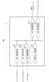
- FIG. 2 is a functional block diagram of a control program and a linked display application installed on a mobile terminal.
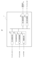
- FIG. 2 is a functional block diagram of a control program and a linked display application installed in the HMD.
- FIG. 3 is an explanatory diagram of operation modes of a mobile terminal.
- FIG. 3 is a diagram showing a comparison of power consumption in each operation mode.
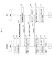
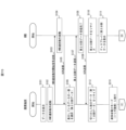
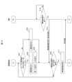
- FIG. 3 is a diagram showing the relationship between operation and power consumption of a mobile terminal in the first embodiment. It is a control flow diagram (first half) of the linked display system according to the first embodiment. It is a control flow diagram (second half) of the linked display system according to the first embodiment.
- FIG. 7 is a diagram showing the relationship between operation and power consumption of a mobile terminal in a second embodiment. It is a control flow diagram (first half) of the linked display system according to the second embodiment.
- FIG. 7 is a control flow diagram (middle part) of the linked display system according to the second embodiment. It is a control flow diagram (second half) of the linked display system according to the second embodiment.
- It is a diagram showing the user's line of sight when the display is turned on by a trigger by the linked display system, (a) shows the field of view through the HMD display when the user is not looking at the screen of the mobile terminal from the front; b) shows the field of view through the HMD display when the user is looking at the screen of the mobile terminal from the front.
- FIG. 7 is a control flow diagram of a linked display system according to a third embodiment.
- FIG. 7 is a diagram showing the relationship between operation and power consumption of a mobile terminal in a fourth embodiment. It is a control flow diagram (first half) of the linked display system according to the fourth embodiment. It is a control flow diagram (second half) of the linked display system according to the fourth embodiment.
- FIG. 6 is a diagram showing an example of a data display screen according to the fifth embodiment, in which (a) is the screen of the mobile terminal before linkage, (b-1) is the screen of the HMD after linkage, and (b-2) is the screen after linkage. Shows the screen of a mobile device. It is a control flow diagram showing the flow of processing according to a fifth embodiment.
- FIG. 7 is a diagram showing an example of a data display screen according to the sixth embodiment, in which (a) is a screen of a mobile terminal before linkage, (b-1) is a screen of an HMD after linkage, and (b-2) is a screen after linkage. Shows the screen of a mobile device. It is a control flow diagram showing the flow of processing according to a sixth embodiment.
- FIG. 6 is a diagram illustrating an example of viewpoint operation when a moving image is displayed on a mobile terminal.
- the present invention is expected to improve the diversification and technology of labor-intensive industries, so the present invention can be applied to Sustainable Development Goals (SDGs) 8.2 (Products and Services) advocated by the United Nations. It can be expected to contribute to increasing economic productivity through diversification, technological improvement, and innovation, particularly in industries that increase value and labor-intensive industries.
- SDGs Sustainable Development Goals 8.2 (Products and Services) advocated by the United Nations. It can be expected to contribute to increasing economic productivity through diversification, technological improvement, and innovation, particularly in industries that increase value and labor-intensive industries.
- FIG. 1 is a system schematic diagram of a linked display system for a mobile terminal 2 and an HMD (head mounted display) 3 according to the present embodiment, with (a) showing before linking and (b) showing after linking.
- HMD head mounted display
- the user 1 Before the linkage shown in FIG. 1(a), the user 1 is operating only the mobile terminal 2 (corresponding to the first information device).
- the mobile terminal 2 is communicatively connected to a web server 6 via a network 5.
- the mobile terminal 2 receives data from the WEB server 6 via the first data acquisition path 41 and displays it on the mobile terminal 2.
- the user 1 After the link shown in FIG. 1(b), the user 1 is wearing the HMD 3 (corresponding to the second information device) and operating the mobile terminal 2.
- the mobile terminal 2 is communicatively connected to a web server 6 via a network 5.
- the mobile terminal 2 receives display data (content) from the WEB server 6 via the first data acquisition path 41 .
- the mobile terminal 2 is communicatively connected (linked) with the HMD 3 and divides the display data obtained from the WEB server 6.
- the divided data to be displayed on the HMD 3 is referred to as second divided data
- the data obtained after cutting out the second divided data from the display data is referred to as first divided data.
- the mobile terminal 2 transfers the second divided data to the HMD 3 via the second data transfer path 42 during linkage.
- the HMD 3 is communicatively connected to the WEB server 6 , the data is divided by the WEB server 6 to create third data, and the mobile terminal 2 is connected from the WEB server 6 via the first data acquisition route 41 .
- the HMD 3 may receive the data from the web server 6 via the third data acquisition path 43.
- the HMD 3 and the mobile terminal 2 may be communicably connected via the second data transfer path 42.
- FIG. 2 is a front view of the external appearance of the mobile terminal 2 according to the present embodiment
- FIG. 3 is a schematic configuration diagram of the mobile terminal 2 according to the present embodiment.
- a display 207 (first display") on which a home button 230, an earpiece 231, a notification lamp 232, an in-camera 206, a distance measurement sensor 213, and a touch panel 208 are stacked. ) is provided.
- a volume button and a power button on the side of the mobile terminal 2
- a speaker 218 see FIG. 3
- a microphone 217 see FIG. 3
- a power supply and communication connector for a speaker
- an out camera 205 see FIG. 3
- a fingerprint sensor etc. on the back side. Note that the arrangement location does not have to be as shown in FIG.
- the mobile terminal 2 includes a processor 201, a RAM 202, a ROM 203, a storage 204, an out camera 205, an in camera 206, a display 207, a touch panel 208, an acceleration sensor 209, a gyro sensor 210, a geomagnetic sensor 211, and a positioning sensor.
- the ROM 203 includes a control program 251 that controls the basic operations of the mobile terminal 2 and a linkage display application 252 (installed in the mobile terminal 2), and the processor 201 expands these programs into the RAM 202 and executes them.
- the linked display application 252 may be stored in the storage 204.
- the storage 204 can store data generated in the process and results of executing the processing program.
- the telephone network communication I/F 214 is a type of communication device that realizes communication functions of mobile communication such as 4G and 5G.
- the distance measurement sensor 213 may be one that calculates the distance to feature points such as the outline of a real object using a method such as a stereo camera, or one that irradiates a light beam two-dimensionally such as a TOF (Time of Flight) method. It may be a device that measures the distance by using the mobile terminal 2, and any device that can measure the distance to the mobile terminal 2 may be used.
- a method such as a stereo camera
- TOF Time of Flight
- the LAN communication I/F 215 is a type of communication device that implements a communication function of wireless communication using the Wi-Fi (registered trademark) standard or the like. Note that other wireless communication means may be used.
- the BT communication I/F 216 is a type of communication device used for cooperation between the mobile terminal 2 and the HMD 3.
- the cooperation between the mobile terminal 2 and the HMD 3 is not limited to BT, and other wireless communication means may be used.
- FIG. 4 is an external view of the HMD 3 according to the present embodiment
- FIG. 5 is a schematic configuration diagram of the HMD 3 according to the present embodiment.
- the HMD 3 mainly includes a controller 331, an out camera 305, a distance sensor 313, a display 307, a positioning sensor 312, a microphone 317, a speaker 318, and an operation key 319a in a frame 330, and the frame 330 is Attach it to the head of 1.
- the display 307 and distance measurement sensor 313 are located in front of the user 1's eyes.
- the out-camera 305 is attached to take an image in front of the line of sight of the user 1, and the distance measurement sensor 313 detects the difference between a real object in real space captured by an image taken by the out-camera 305 (corresponding to a "front image”). Measure distance.
- the components shown in the controller 331 are a processor 301, a RAM 302, a ROM 303, and a storage 304 (see FIG. 5). Note that the arrangement location does not have to be as shown in FIG. 4.
- the HMD 3 includes a processor 301, RAM 302, ROM 303, storage 304, out camera 305, in camera 306, display 307, acceleration sensor 309, gyro sensor 310, geomagnetic sensor 311, positioning sensor 312, distance sensor 313, a LAN communication I/F 315, a BT communication I/F 316, a microphone 317, a speaker 318, a key input I/F 319, and a battery 320, which are connected to each other via a bus 321.
- FIG. 6 is a functional block diagram of the control program 251 and the linked display application 252 installed on the mobile terminal 2.
- the control program 251 includes a first communication control section 251a and a first display control section 251b.
- the first communication control unit 251a communicates with the HMD 3 and the WEB server 6.
- the first display control unit 251b controls the display on the display 207 during the normal mode.
- the linkage display application 252 includes a first linkage display section 252a, a first operation reception section 252b, and an operation mode control section 252d.
- the first linkage display section 252a controls the display of the display 207 during the linkage operation. Also resizes images.
- the first operation reception unit 252b receives an operation by touch operation on the touch panel 208. Further, the first operation reception section 252b includes a first image recognition section 252c. The first image recognition unit 252c performs image recognition processing on the image captured by the in-camera 206, and determines whether the user 1 is looking at the mobile terminal 2 from the front.
- the operation mode control unit 252d switches the operation between a normal mode in which all functions are turned on, a power saving mode, a linked power saving mode (always screen on), and a linked power saving mode (trigger return). The contents of each mode will be described later.
- Each of the above units is configured by the processor 201 loading a control program 251 and a link display application 252 into the RAM 202 and executing them.
- FIG. 7 is a functional block diagram of the control program 351 and the linked display application 352 installed on the HMD 3.
- the control program 351 includes a second communication control section 351a and a second display control section 351b.
- the second communication control unit 351a communicates with the mobile terminal 2 and the web server 6.
- the second display control unit 351b controls the display on the display 307 when it is not linked to the mobile terminal 2.
- the linkage display application 352 includes a second linkage display section 352a and a second operation reception section 352b.
- the second linkage display section 352a controls the display of the display 307 during the linkage operation. Also resizes images.
- the second operation reception section 352b includes a second image recognition section 352c and a line of sight detection section (line of sight detection sensor) 352d.
- the second image recognition unit 352c performs image recognition processing on the captured image captured by the out-camera 305, and recognizes the mobile terminal 2.
- the line-of-sight detection unit 352d detects the area where the eyes of the user 1 are captured from the image captured by the in-camera 306, and performs line-of-sight tracking.
- the second operation reception unit 352b can determine whether the user 1 is looking at the mobile terminal 2 by overlapping the result of the gaze tracking and the photographed image of the mobile terminal 2 recognized by the second image recognition unit 352c. Furthermore, as a result of gaze tracking, it is determined where the point of view (viewpoint) of the user 1 is located in the angle of view of the out-camera 305, and the position of the point of view and the movement including the movement of the point of view are associated with the operation of the linked display. The operation may also be accepted.
- the line-of-sight sensor includes the in-camera 306 and the line-of-sight detection section 352d.
- Each of the above units is configured by the processor 301 loading a control program 351 and a link display application 352 into the RAM 302 and executing them.
- FIG. 8 is a diagram showing an example 1 of the data display screen by the linked display system, in which (a) shows the screen of the mobile terminal 2 before linking, (b-1) shows the screen of the HMD 3 after linking, and ( b-2) shows the screen of the mobile terminal 2 after linking.
- FIG. 8 is an example of displaying data consisting only of text.
- the data is divided in advance at the time of data creation, and the user 1 may specify the data to be sent to the HMD 3 by touching text on the touch panel 208. Alternatively, the area may be specified on the touch panel 208.
- FIG. 8 shows an example of a screen display of data consisting only of text
- part of the data may be an image.
- the image may be transmitted to the HMD 3, or the image may be displayed on the mobile terminal 2 and text may be displayed on the HMD 3, and the type of data and the type of divided data do not matter.
- FIG. 9 is an explanatory diagram of the operation mode of the mobile terminal.
- the operating states of the mobile terminal 2 include a normal mode, a power saving mode, a linked power saving mode (always screen on) that is executed only during linked operation (linked operation), and linked power saving mode (trigger return). There is.
- Normal mode is a mode in which all functions are turned on.
- the mobile terminal 2 When the mobile terminal 2 is in use and the linked display is not displayed, it operates in the normal mode. If no operation is performed for a predetermined period of time in normal mode, the device will switch to power saving mode.
- the power saving mode is a mode in which, for example, only wireless communication (telephone network communication I/F 214) is turned on and other functions are turned off, and is a mode to which the mobile terminal 2 changes if it is not operated for a predetermined period of time.
- the power saving mode is the operating mode with the lowest power consumption. Therefore, the screen display on the display 207 is also turned off. In order to turn on the screen display from the power saving mode, it is necessary to touch the touch panel 208 or operate the home button 230. Additionally, if a passcode has been set, you will be prompted to enter the passcode.
- the mobile terminal 2 has two modes: one mode disables the power saving mode and operates in normal mode, and the other mode operating in power saving mode or linked power saving mode.
- the linked power saving mode includes linked power saving mode (always screen on) and linked power saving mode (trigger return).
- the linked power saving mode (always screen on)
- only the minimum functions necessary for linked display with the HMD 3 are turned on, other functions are turned off, and the display operates with less power than the normal mode.
- the telephone network communication I/F 214, inter-device connection with the mobile terminal 2 through BT connection, and screen display are turned on, and other functions are turned off.
- voice recognition for voice operations may be turned on.
- the linked power saving mode (trigger return) turns off the screen display when no operations are performed. In that case, a trigger must be detected to turn on the screen display. By turning on the function of detecting a trigger and detecting, for example, an operation by the mobile terminal 2 or HMD 3 that becomes a trigger, it is possible to switch the screen display on and off.
- FIG. 10 is a diagram showing a comparison of power consumption in each operation mode.
- the power consumption is lower in the linked power saving mode (always on screen), and even lower in the linked power saving mode (trigger return). Power consumption is lower in power saving mode than in linked power saving mode (trigger return).
- the first embodiment is an embodiment in which the power saving mode is disabled while the mobile terminal and the HMD are linked, and the screen of the mobile terminal is always on and operates in the normal mode.
- FIG. 11 is a diagram showing the relationship between the operation of the mobile terminal and power consumption in the first embodiment.
- the cooperative operation between the mobile terminal 2 and the HMD 3 is started at time t1 while the portable terminal 2 is in normal operation, that is, the device connection is started and the HMD cooperative operation start signal is affirmed.
- the power saving mode is switched from valid to invalid.
- the power saving mode is disabled during the linked operation, so that the screen of the mobile terminal 2 remains on even if no operation is performed for a certain period of time or more.
- the power saving mode is switched from disabled to enabled, and normal operation is performed. Therefore, while the power saving mode is disabled during linked operation, power consumption is high, but the screen can be viewed at any time, so work efficiency does not decrease.
- FIG. 12 is a control flow diagram (first half) of the linked display system according to the first embodiment.
- FIG. 13 is a control flow diagram (second half) of the linked display system according to the first embodiment.
- the mobile terminal 2 receives data from the WEB server 6 and displays it on the display 207 (S101).
- an HMD linked operation start signal is transmitted from the mobile terminal 2 to the HMD 3 (S103).
- the HMD 3 When the pairing is completed between the HMD 3 and the mobile terminal 2 and the HMD 3 receives the link operation start signal, the HMD 3 starts the HMD link operation (S104) and sends an acknowledgment (ACK packet) to the mobile terminal 2. (S105).
- the first operation reception unit 252b accepts a data division operation via the touch panel 208.
- the first linked display unit 252a divides the data according to the data division operation, selects the data within the divided area as the second divided data (S106), and transmits it to the HMD 3 (S107).
- the second communication control unit 351a of the HMD 3 When the second communication control unit 351a of the HMD 3 completes receiving the second divided data (S108), it transmits an acknowledgment to the mobile terminal 2 (S109).
- the second linked display unit 352a of the HMD 3 resizes the second divided data according to the size of the display 307 (S110) and displays the second divided data on the display 307 (S111).
- the first linked display unit 252a resizes the first divided data according to the size of the display 207 (S112) and displays the first divided data on the display 207 (S113). ).
- the operation mode control unit 252d of the mobile terminal 2 disables the power saving mode (S114). As a result, the screen of the display 207 is always on, regardless of whether or not the mobile terminal 2 is operated, until the linked display of the HMD 3 is canceled.
- the second link display section 352a of the HMD 3 continues to display the link until the HMD link operation is completed (S115: No).
- the mobile terminal 2 When the mobile terminal 2 receives the link operation end signal, it ends the link operation (S117).
- the first linked display unit 252a returns an affirmative response (S118), erases the display of the first divided data that was being displayed (S119), and the first display control unit 251b redisplays the original data on the display 207 ( S120).
- the operation mode control unit 252d enables the power saving mode (S121).
- the HMD 3 Upon receiving the affirmative response in step S118, the HMD 3 erases the display of the second divided data displayed on the display 307 (S122).
- the power saving mode of the mobile terminal 2 is disabled and the mobile terminal 2 always operates in the normal mode.
- the screen of the mobile terminal 2 is always on during linkage, regardless of whether the mobile terminal 2 is operated or not, so even if the user 1 looks at the screen of the mobile terminal 2 at any time during linkage, the mobile terminal 2
- the first divided data displayed on the screen can be viewed without operating the .
- the user can view the second divided data while doing the work at hand without having to move his/her line of sight, which can be expected to improve work efficiency.
- the second embodiment is an embodiment in which, while the mobile terminal 2 and HMD 3 are linked, the power saving mode remains valid, and when the HMD 3 detects a trigger, the screen display of the mobile terminal 2 is turned on and operates in the normal mode. .
- the mobile terminal 2 switches to the power saving mode if no operation is performed for a predetermined period of time while the mobile terminal 2 is running in the normal mode, but in the second embodiment and the third embodiment described later, when the linked operation is activated, the mobile terminal 2 switches from the normal mode to the power saving mode. Transition to linked power saving mode (trigger return).
- FIG. 14 is a diagram showing the relationship between operation and power consumption of a mobile terminal in the second embodiment.
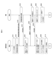
- FIG. 15 is a control flow diagram (first half) of the linked display system according to the second embodiment.
- FIG. 16 is a control flow diagram (middle part) of the linked display system according to the second embodiment.
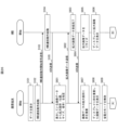
- FIG. 17 is a control flow diagram (second half) of the linked display system according to the second embodiment.
- the cooperative operation between the mobile terminal 2 and the HMD 3 is started at time t1 while the portable terminal 2 is in normal operation, that is, the device connection is started and the HMD cooperative operation start signal is affirmed.
- the mobile terminal 2 receives the response, it shifts to the linked power saving mode (trigger return) and the screen display of the mobile terminal 2 is turned off.
- the activation of the linked operation and the transition to the linked power saving mode (trigger return) do not have to be simultaneous.
- the HMD 3 detects an operation using a gesture movement, for example, the detection of the operation is used as a trigger to switch the screen display of the mobile terminal 2 from off to on. After that, if no operation is performed for a certain period of time, the screen display will turn off. This switching of the screen display from on to off is the same as the standard operation in power saving mode.
- the linked power saving mode (trigger return) is enabled and the mode is switched to the normal mode, and the normal operation is performed. Therefore, due to the linked operation, the linked power saving mode (trigger return) is enabled and the screen display is turned off, so the time the screen display is on is shortened and power consumption is suppressed, while the screen display is triggered by the detection of an operation. Since it is turned on, work efficiency does not decrease.
- steps S101 to S112 are the same as in the first embodiment, so repeated explanation will be omitted.
- the operation mode control unit 252d of the mobile terminal 2 causes the mobile terminal 2 to shift to the linked power saving mode (trigger return) (S210).
- the second linked display unit 352a determines that the user 1 is looking at the mobile terminal 2 (S201: Yes), it transmits a screen display on signal to the mobile terminal 2 (S202).
- the second linked display unit 352a determines that the user 1 is not looking at the mobile terminal 2 (S201: No), it transmits a screen display off signal to the mobile terminal 2 (S203).
- the first linked display section 252a turns on the screen display of the display 207 (S205) and displays the first divided data (S206).
- the first linked display section 252a turns off the screen display on the display 207 (S207).
- the mobile terminal 2 returns to step S204 and repeats the process until it receives the HMD linkage operation end signal from the HMD 3 (S208: No).
- the HMD 3 returns to step S201 and repeats the process until an instruction to end the HMD linked operation is input by gesture input or gaze input (S115: No).
- the HMD 3 transmits a linked action end signal to the mobile terminal 2 (S116).
- the mobile terminal 2 When the mobile terminal 2 receives the link operation end signal (S208: Yes), it ends the HMD link operation (S117), and the first link display unit 252a returns an affirmative response (S118).
- the mobile terminal 2 turns on the screen display of the display 207 (S209) and erases the display of the first divided data that was being displayed (remaining on the display 207). (S119), the first display control unit 251b redisplays the original data on the display 207 (S120). The operation mode control unit 252d then cancels the linked power saving mode (trigger return) (S211). Thereby, the mobile terminal 2 shifts to the normal mode.
- the HMD 3 Upon receiving the affirmative response in step S118, the HMD 3 erases the display of the second divided data displayed on the display 307 (S122).
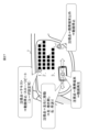
- FIG. 18 is a diagram showing the user's line of sight when turning on the display triggered by the linked display system, and (a) shows the display 307 of the HMD 3 when the user 1 is not looking at the screen of the mobile terminal 2 from the front. (b) shows the field of view through the display 307 of the HMD 3 when the user 1 is looking at the screen of the mobile terminal 2 from the front.
- FIG. 18(a) although the mobile terminal 2 is shown in the left corner of the user's field of view, the user 1 is not looking at the mobile terminal 2 from the front, so the screen display on signal (trigger signal) is not output.
- the state shown in FIGS. 18(a) and 18(b) is determined by the second image recognition unit 352c performing image recognition processing on the image captured by the out-camera 305. It recognizes the type of subject and recognizes whether the mobile terminal 2 is included in the image (corresponding to the recognition of the first information device image). It is only necessary to judge whether it is directly facing the HMD 3.
- the mobile terminal 2 and the HMD 3 turn on the screen display only when the user 1 looks at the screen of the mobile terminal 2 while the mobile terminal 2 and the HMD 3 are linked. You can view 1-part data.
- the screen display is turned off when the user 1 is not looking at the screen of the mobile terminal 2, power consumption during coordination can be reduced compared to the first embodiment in which it is always on.
- the user can view the second divided data while doing the work at hand without having to move his/her line of sight, which can be expected to improve work efficiency.
- the third embodiment is an embodiment in which the power saving mode remains valid while the mobile terminal 2 and HMD 3 are linked, and when the mobile terminal 2 detects a trigger, the screen display of the mobile terminal 2 is turned on and operates in the normal mode. It is. Generally, the mobile terminal 2 switches to the power saving mode if no operation is performed for a predetermined period of time while the normal mode is being executed, but in the second and third embodiments as well, the linked operation is activated and the power saving mode is switched from the normal mode to the power saving mode. Transition to power mode (trigger return). Further, the difference from the second embodiment is that the trigger detection is executed by the HMD 3 in the second embodiment, but is executed by the mobile terminal 2 in the third embodiment.
- FIG. 19 is a control flow diagram of the linked display system according to the third embodiment.
- Steps S101 to S112 and Step S210 are the same as those in the second embodiment, so repeated explanation will be omitted.
- the first image recognition unit 252c of the mobile terminal 2 performs image recognition processing on the image captured by the in-camera 206, and recognizes the face of the user 1. If the first linked display unit 252a determines that the user 1 is looking at the mobile terminal 2 from the front based on the size of the face image and the direction of the face (S301: Yes), the first linked display unit 252a changes the screen display of the display 207. It is turned on (S204) and the first divided data is displayed (S205).
- the first linked display unit 252a determines that the user 1 is not looking at the mobile terminal 2 from the front (S301: No), it turns off the screen display of the display 207 (S207).
- the first linkage display unit 252a indicates whether the user 1 is looking at the mobile terminal 2 from the front. For example, if the first image recognition unit 252c can recognize both eyes from the image of the in-camera 206, It may be determined that the user is looking at the mobile terminal 2.
- step S301 If the first link display unit 252a does not receive the HMD link operation end signal (S302: No), the process returns to step S301.
- the mobile terminal 2 When the mobile terminal 2 receives the HMD linkage operation end signal (S302: Yes), it executes the same process as in the second embodiment, so redundant explanation will be omitted.
- the mobile terminal 2 and the HMD 3 turn on the screen display only when the user 1 looks at the screen of the mobile terminal 2 while the mobile terminal 2 and the HMD 3 are linked. You can view 1-part data.
- the HMD 3 since the HMD 3 is worn on the head, it is required to be lightweight, making it difficult to mount a large-capacity battery.
- the trigger is detected by the mobile terminal 2, so the HMD 3 detects the trigger for switching the screen display on and off of the mobile terminal 2, and transmits the screen display on signal and the screen display off signal to the mobile terminal. 2, the power consumption of the HMD 3 can be reduced compared to the second embodiment.
- the user can view the second divided data while doing the work at hand without having to move his/her line of sight, which can be expected to improve work efficiency.
- the fourth embodiment is an embodiment in which the screen display of the mobile terminal 2 is always turned on while the mobile terminal 2 and the HMD 3 are linked, and the mobile terminal 2 operates in a linked power saving mode (screen always on).
- FIG. 20 is a diagram showing the relationship between operation and power consumption of a mobile terminal in the fourth embodiment.
- FIG. 21 is a control flow diagram (first half) of the linked display system according to the fourth embodiment.
- FIG. 22 is a control flow diagram (second half) of the linked display system according to the fourth embodiment.
- the cooperative operation between the mobile terminal 2 and the HMD 3 is started at time t1 while the portable terminal 2 is in normal operation, that is, the device connection is started and the HMD cooperative operation start signal is affirmed.
- the mobile terminal 2 receives the response, it shifts to a linked operation mode (always screen on) and then shifts to a linked power saving mode. At this time, the screen display of the mobile terminal 2 is always on.
- the linked operation ends at time t3, the mode switches to normal mode and normal operation is performed. Therefore, the linked operation saves power by shifting to the linked power saving mode (always screen on) which consumes less power than the normal mode, and the screen display is always on, so work efficiency does not decrease.
- steps S101 to S113 are the same as in the first embodiment, so repeated explanation will be omitted.
- the operation mode control unit 252d of the mobile terminal 2 shifts to the linked power saving mode (screen always on) (S401).
- the second link display section 352a of the HMD 3 continues to display the link until the HMD link operation is completed (S115: No).
- the mobile terminal 2 When the mobile terminal 2 receives the link operation end signal, it ends the link operation (S117).
- the first linked display unit 252a returns an affirmative response (S118), erases the display of the first divided data that was being displayed (S119), and the first display control unit 251b redisplays the original data on the display 207 ( S120).
- the operation mode control unit 252d then cancels the linked power saving mode (always screen on) (S402). Thereby, the mobile terminal 2 shifts to the normal mode.
- mobile terminal 2 can perform screen display, voice search, wireless phone calls, and BT communication, but for example, applications, data synchronization, Wi-Fi, location information acquisition, etc. are stopped. Power consumption can be reduced compared to normal mode.
- the screen of the mobile terminal 2 is always on regardless of whether the mobile terminal 2 is operated or not, so even if the user 1 looks at the screen of the mobile terminal 2 at any time during coordination, the user 1 does not have to operate the mobile terminal 2.
- the first divided data displayed on the screen can be viewed.
- the user can view the second divided data while doing the work at hand without having to move his/her line of sight, which can be expected to improve work efficiency.
- the fifth embodiment is an embodiment in which data consisting only of images is displayed in conjunction with the mobile terminal 2 and the HMD 3.
- FIG. 23 is a diagram showing an example of a data display screen according to the fifth embodiment, in which (a) is the screen of the mobile terminal 2 before linkage, (b-1) is the screen of HMD 3 after linkage, and (b-2 ) indicates the screen of the mobile terminal 2 after linkage.
- thumbnail images are displayed on the screen of the mobile terminal 2 (see FIG. 23(a)).
- data to be sent to the HMD 3 is specified.
- the display order may be set in advance when creating the data, and the first image may be sent to the HMD 3.
- the HMD 3 After linking, the HMD 3 enlarges (optimizes) the data display size to match the screen size and displays it (see FIG. 23 (b-1)). Further, on the screen of the mobile terminal 2, a mark indicating that the thumbnail image corresponding to the selected image has been selected is superimposed (see FIG. 23(b-2)).
- the data displayed on the HMD 3 can be changed by operating the HMD 3's line of sight. For example, you can change to the next data by blinking twice.
- FIG. 24 is a control flow diagram showing the flow of processing according to the fifth embodiment.
- image data A is selected from among the thumbnail images displayed on the screen of the mobile terminal 2 (S501) and transmitted to the HMD 3 (S502).
- the HMD 3 receives the image data A (S503) and returns an acknowledgment (S504).
- the HMD 3 resizes the image data A (S505) and displays it on the display 307 (S506).
- the mobile terminal 2 that received the positive response in step S504 superimposes a frame on the image data A (S507), displays the image data A with the frame superimposed on the display 207 (S508), and disables the power saving mode. (S114). Since the subsequent processing is the same as that shown in FIG. 13, repeated explanation will be omitted.
- the mobile terminal 2 and the HMD 3 are linked, and one image can be selected from a plurality of thumbnail images displayed on the mobile terminal 2 and enlarged and displayed on the HMD 3, so that the image that you want to focus on can be selected.
- Data A becomes easier to visually recognize.
- the sixth embodiment is an embodiment in which one image and image data consisting of a part of the image are displayed in conjunction with the mobile terminal 2 and the HMD 3.
- FIG. 25 is a diagram showing an example of a data display screen according to the sixth embodiment, in which (a) is the screen of the mobile terminal 2 before linkage, (b-1) is the screen of HMD 3 after linkage, and (b-2 ) indicates the screen of the mobile terminal 2 after linkage.
- an expandable area is set in advance at the time of data creation, and the user 1 specifies the HMD transmission data by touching it. Furthermore, the area may be designated by the user's line of sight through the HMD 3.
- the data display size is expanded (optimized) and displayed according to the screen size (see FIG. 25 (b-1)).
- the data displayed on the HMD 3 may be changed by operating the HMD 3's line of sight. For example, it may be possible to change to the next data, change the enlargement position, change the magnification, etc. by blinking twice.
- FIG. 26 is a control flow diagram showing the flow of processing according to the sixth embodiment.
- the area to be enlarged of the image displayed on the screen of the mobile terminal 2 is specified and enlarged image data is specified (S601), and the data is sent to the HMD 3 (S602).
- the HMD 3 receives the enlarged image data (S603) and returns an acknowledgment (S604).
- the HMD 3 resizes the enlarged image data (S605) and displays it on the display 307 (S606).
- the mobile terminal 2 that received the affirmative response in step S604 superimposes a frame on the enlarged part of the image data (S607), displays the image data with the frame superimposed on the display 207 (S608), and disables the power saving mode ( S609). Since the subsequent processing is the same as that shown in FIG. 13, repeated explanation will be omitted.
- the mobile terminal 2 and the HMD 3 are linked, and a part of the image displayed on the mobile terminal 2 can be specified and enlarged and displayed on the HMD 3, so that it is easy to visually recognize the part that you want to focus on. Become.
- ⁇ Seventh embodiment> 7th Embodiment is embodiment regarding the variation of the operation example of HMD3.
- the operation example according to this embodiment may be used as appropriate in the first to sixth embodiments described above.
- the operation of the HMD 3 is not limited to line of sight detection.
- voice input gesture input, frame tapping, etc. may be used.
- the number of divisions of data being displayed on the mobile terminal 2 is not limited to two.
- the data may be divided into three or more parts, and the divided data may be sent to the HMD 3 and displayed in parallel on the display 307. Further, data divided sequentially may be displayed on the display 307.
- the video may be manipulated by line-of-sight operation.
- FIG. 27 is a diagram showing an example of viewpoint operation when a moving image is displayed on the mobile terminal 2.
- the video may be displayed on the mobile terminal 2, text etc. may be displayed on the HMD 3, and the video may be manipulated depending on the position and time of the point of interest.
- the operation of continuously looking at one point for a predetermined period of time while keeping one's line of sight on the mobile terminal 2 may be used as a video playback operation.
- the action of viewing the mobile terminal 2 through the HMD 3 and moving the line of sight to the left while keeping the line of sight on the mobile terminal 2 may be a rewind operation, and the action of moving the line of sight to the right may be a fast forward operation.
- the operation of continuing to look at a point other than the mobile terminal 2 through the HMD 3 for a predetermined period of time may be used as a video stopping operation.
- the HMD 3 may be configured to allow customization of video operations corresponding to user operations.
- the processor 301 of the HMD 3 When the processor 301 of the HMD 3 detects an operation corresponding to the movement of the line of sight, it generates an instruction signal indicating the content of the operation and transmits it to the mobile terminal 2. When the mobile terminal 2 receives the instruction signal, the mobile terminal 2 operates the video display on the display 207 of the mobile terminal 2 according to the operation content indicated by the instruction signal, and the text display on the HMD 3 changes in conjunction with this.
- the video being displayed on the HMD 3 can be played, fast forwarded, rewinded, and stopped by inputting the viewpoint, so that the user 1 can perform operations to play, fast forward, rewind, and stop the video while the user 1 is working. Even in a situation where you cannot take your hands off the mobile terminal 2, you can perform operations related to video viewing without operating the mobile terminal 2 with your hands.
- the first information device may be a tablet terminal instead of a smartphone
- the second information device may be smart glasses instead of a head-mounted display.
- the trigger event for restarting the screen display of the mobile terminal 2 is that the face image of the user 1 was recognized from the image taken by the in-camera 206 of the mobile terminal 2, and that the face image of the user 1 was recognized from the image taken by the out-camera 305 of the HMD 3.
- the mobile terminal image is recognizable and is not limited to being covered by the user's 1 line of sight. For example, when a link destination is displayed on the display 307 of the HMD 3, if the user blinks twice while the point of gaze is overlapping the link destination, the linked page may be displayed on the display 207 of the mobile terminal 2. Further, voice recognition of user 1's utterance such as “screen on” may also be used as the trigger event.
- the related data sent from the mobile terminal 2 to the HMD 3 is not limited to images corresponding to thumbnail images, divided data of data being displayed on the mobile terminal 2, or text in videos.
- a sentence in the first language is displayed on the display 207 of the mobile terminal 2
- a sentence translated into the second language may be displayed on the HMD 3 as related data.
- each processing example may be independent programs, or a plurality of programs may constitute one application program. Furthermore, the order in which each process is performed may be changed.
- Some or all of the functions of the present invention described above may be realized by hardware, for example, by designing an integrated circuit.
- the functions may be realized by software by having a processor unit or the like interpret and execute an operating program for realizing each function.
- Hardware and software may be used together.
- control lines and information lines shown in the figures are those considered necessary for explanation, and do not necessarily show all control lines and information lines on the product. In reality, almost all components may be considered to be interconnected.
- the embodiment includes the following aspects.
- a linked display system in which a first information device and a second information device are communicatively connected,
- the first information device includes a first display, a first communication device that transmits and receives data to and from the second information device, and a first processor that controls operations of the first display and the first communication device
- the second information device includes a second display, a second communication device that transmits and receives data to and from the first information device, and a second processor that controls operations of the second display and the second communication device.
- the first information device operates in a normal mode in which the screen display of the first display is on and maintains inter-device communication with the second information device, and a predetermined period of time during which no operations are performed on the first information device.
- a power saving mode in which the screen display of the first display is turned off, and when the linked operation between the first information device and the second information device is started, the power saving mode of the first information device is activated. mode is disabled and the screen display of the first display is always on, transmits second divided data consisting of a part of the display data to be displayed on the first display to the second information device, and Displaying the first divided data after cutting out the second divided data from the data on the first display, and displaying the second divided data on the second display when the second information device receives the second divided data.
- Linked display system in which the screen display of the first display is turned off, and when the linked operation between the first information device and the second information device is started, the power saving mode of the first information device is activated. mode is disabled and the screen display of the first display is always on, transmits second divided data consisting of a part of the display data to be displayed on the first display to the second information device, and Displaying the first divided data after cutting out the second divided data from the data on the first display, and
- a linked display system in which a first information device and a second information device are communicatively connected,
- the first information device includes a first display, a first communication device that transmits and receives data to and from the second information device, and a first processor that controls operations of the first display and the first communication device
- the second information device includes a second display, a second communication device that transmits and receives data to and from the first information device, and a second processor that controls operations of the second display and the second communication device.
- the first information device operates in a normal mode in which the screen display of the first display is on and maintains inter-device communication with the second information device, and a predetermined period of time during which no operations are performed on the first information device.
- a first cooperative power saving mode in which the screen display of the first display is turned off, and when the cooperative operation between the first information device and the second information device is started, the first information device One of the display data to be displayed on the first display when a trigger signal is input to enable the first linked power saving mode and turn on the screen display while the screen display of the first display is off.
- the second information device display the first divided data after cutting out the second divided data from the display data on the first display, and display the first divided data on the first display.
- a linked display system in which a first information device and a second information device are communicatively connected,
- the first information device includes a first display, a first communication device that transmits and receives data to and from the second information device, and a first processor that controls operations of the first display and the first communication device
- the second information device includes a second display, a second communication device that transmits and receives data to and from the first information device, and a second processor that controls operations of the second display and the second communication device.
- the first information device operates in a normal mode in which the screen display of the first display is on and inter-device communication with the second information device is maintained, and in which the first display is always on and other predetermined functions are off.
- Switching to a second linked power saving mode transmitting second divided data consisting of a part of the display data to be displayed on the first display to the second information device, and cutting out the second divided data from the display data.
- displaying the first divided data on the first display after receiving the second divided data and displaying the second divided data on the second display when the second information device receives the second divided data.
- a linked display method executed by communicatively connecting a first information device and a second information device, activating a cooperative operation between the first information device and the second information device; disabling the power saving mode of the first information device and switching the screen display of a first display included in the first information device to always on; transmitting second divided data consisting of a part of the display data to be displayed on the first display to the second information device; displaying the first divided data after cutting out the second divided data from the display data on the first display; the second information device receiving the second divided data; Displaying the second divided data on a second display included in the second information device; Linked display methods including.
Landscapes
- Engineering & Computer Science (AREA)
- Theoretical Computer Science (AREA)
- Physics & Mathematics (AREA)
- General Physics & Mathematics (AREA)
- General Engineering & Computer Science (AREA)
- Human Computer Interaction (AREA)
- Multimedia (AREA)
- General Health & Medical Sciences (AREA)
- Oral & Maxillofacial Surgery (AREA)
- Health & Medical Sciences (AREA)
- Computer Hardware Design (AREA)
- User Interface Of Digital Computer (AREA)
- Digital Computer Display Output (AREA)
- Controls And Circuits For Display Device (AREA)
Priority Applications (4)
| Application Number | Priority Date | Filing Date | Title |
|---|---|---|---|
| CN202280098528.XA CN119604927A (zh) | 2022-08-09 | 2022-08-09 | 协同显示系统以及协同显示方法 |
| US19/100,084 US12596517B2 (en) | 2022-08-09 | 2022-08-09 | Linked display system and linked display method |
| PCT/JP2022/030420 WO2024034011A1 (ja) | 2022-08-09 | 2022-08-09 | 連係表示システム及び連係表示方法 |
| JP2024540117A JP7812453B2 (ja) | 2022-08-09 | 2022-08-09 | 連係表示システム |
Applications Claiming Priority (1)
| Application Number | Priority Date | Filing Date | Title |
|---|---|---|---|
| PCT/JP2022/030420 WO2024034011A1 (ja) | 2022-08-09 | 2022-08-09 | 連係表示システム及び連係表示方法 |
Publications (1)
| Publication Number | Publication Date |
|---|---|
| WO2024034011A1 true WO2024034011A1 (ja) | 2024-02-15 |
Family
ID=89851245
Family Applications (1)
| Application Number | Title | Priority Date | Filing Date |
|---|---|---|---|
| PCT/JP2022/030420 Ceased WO2024034011A1 (ja) | 2022-08-09 | 2022-08-09 | 連係表示システム及び連係表示方法 |
Country Status (4)
| Country | Link |
|---|---|
| US (1) | US12596517B2 (https=) |
| JP (1) | JP7812453B2 (https=) |
| CN (1) | CN119604927A (https=) |
| WO (1) | WO2024034011A1 (https=) |
Citations (4)
| Publication number | Priority date | Publication date | Assignee | Title |
|---|---|---|---|---|
| JP2012178097A (ja) * | 2011-02-28 | 2012-09-13 | Olympus Corp | 頭部装着型表示装置及びクライアント装置 |
| JP2015201160A (ja) * | 2014-04-01 | 2015-11-12 | カシオ計算機株式会社 | 情報処理システム、情報機器、装着型情報機器、情報機器の機能実行方法、装着型情報機器の情報通知方法、装着型情報機器の情報機器制御方法、装着型情報機器の画像送信方法、及びプログラム |
| US20170337897A1 (en) * | 2016-05-17 | 2017-11-23 | Lg Electronics Inc. | Head mounted display device and method for controlling the same |
| JP2021176004A (ja) * | 2020-04-24 | 2021-11-04 | 株式会社日立製作所 | 表示装置、表示システムおよび表示方法 |
Family Cites Families (9)
| Publication number | Priority date | Publication date | Assignee | Title |
|---|---|---|---|---|
| JP2007334237A (ja) | 2006-06-19 | 2007-12-27 | Fujifilm Corp | 表示システムおよび機器制御システム |
| US8743083B2 (en) * | 2010-10-15 | 2014-06-03 | Logitech Europe, S.A. | Dual mode touchpad with a low power mode using a proximity detection mode |
| US20180199200A1 (en) * | 2017-01-12 | 2018-07-12 | Microsoft Technology Licensing, Llc | Location-based authentication |
| JP2019036914A (ja) | 2017-08-21 | 2019-03-07 | ウエストユニティス株式会社 | 連携表示システム |
| KR102481894B1 (ko) * | 2017-11-06 | 2022-12-28 | 삼성전자 주식회사 | 전자 장치 및 이를 이용한 화면 공유 방법 |
| WO2021064823A1 (ja) | 2019-09-30 | 2021-04-08 | マクセル株式会社 | 連携表示システム及びヘッドマウントディスプレイ |
| KR102880629B1 (ko) * | 2019-11-19 | 2025-11-04 | 삼성전자주식회사 | 디스플레이 기기, 모바일 기기, 디스플레이 기기의 화면 미러링 방법 및 모바일 기기의 화면 미러링 방법 |
| US11333892B2 (en) | 2020-04-24 | 2022-05-17 | Hitachi, Ltd. | Display apparatus, display system, and display method |
| CN118215931A (zh) * | 2021-11-09 | 2024-06-18 | 三星电子株式会社 | 用于在电子装置和可穿戴电子装置之间提供与增强现实服务相关的内容的方法和装置 |
-
2022
- 2022-08-09 CN CN202280098528.XA patent/CN119604927A/zh active Pending
- 2022-08-09 JP JP2024540117A patent/JP7812453B2/ja active Active
- 2022-08-09 US US19/100,084 patent/US12596517B2/en active Active
- 2022-08-09 WO PCT/JP2022/030420 patent/WO2024034011A1/ja not_active Ceased
Patent Citations (4)
| Publication number | Priority date | Publication date | Assignee | Title |
|---|---|---|---|---|
| JP2012178097A (ja) * | 2011-02-28 | 2012-09-13 | Olympus Corp | 頭部装着型表示装置及びクライアント装置 |
| JP2015201160A (ja) * | 2014-04-01 | 2015-11-12 | カシオ計算機株式会社 | 情報処理システム、情報機器、装着型情報機器、情報機器の機能実行方法、装着型情報機器の情報通知方法、装着型情報機器の情報機器制御方法、装着型情報機器の画像送信方法、及びプログラム |
| US20170337897A1 (en) * | 2016-05-17 | 2017-11-23 | Lg Electronics Inc. | Head mounted display device and method for controlling the same |
| JP2021176004A (ja) * | 2020-04-24 | 2021-11-04 | 株式会社日立製作所 | 表示装置、表示システムおよび表示方法 |
Also Published As
| Publication number | Publication date |
|---|---|
| US12596517B2 (en) | 2026-04-07 |
| CN119604927A (zh) | 2025-03-11 |
| JPWO2024034011A1 (https=) | 2024-02-15 |
| US20260037205A1 (en) | 2026-02-05 |
| JP7812453B2 (ja) | 2026-02-09 |
Similar Documents
| Publication | Publication Date | Title |
|---|---|---|
| EP2895911B1 (en) | Apparatus and method of providing user interface on head mounted display and head mounted display thereof | |
| KR101655812B1 (ko) | 휴대 단말기 및 그 동작 방법 | |
| US20150143283A1 (en) | Information processing device, display control method, and program | |
| KR20210086103A (ko) | 디스플레이 기기, 모바일 기기, 그에 따른 디스플레이 기기를 통해 수행되는 영상 통화 방법 및 그에 따른 모바일 기기를 통해 수행되는 영상 통화 방법 | |
| CN113938748B (zh) | 视频播放方法、装置、终端、存储介质及程序产品 | |
| WO2012023581A1 (ja) | 画像表示システム、画像表示システムに含まれる携帯型情報処理装置のためのコンピュータプログラム、及び画像表示方法 | |
| EP3299946B1 (en) | Method and device for switching environment picture | |
| US12608128B2 (en) | Device interaction method, electronic device, and interaction system | |
| JP7777190B2 (ja) | ヘッドマウントディスプレイ | |
| CN111093023A (zh) | 视频拍摄方法及电子设备 | |
| CN110673770B (zh) | 消息展示方法及终端设备 | |
| EP2586203A1 (en) | Information processing apparatus, information processing system and information processing method | |
| KR20140035861A (ko) | 헤드 마운트 디스플레이를 위한 사용자 인터페이스 제공 장치 및 방법 | |
| CN107608606A (zh) | 一种图片显示方法、移动终端及计算机可读存储介质 | |
| CN110163949B (zh) | 一种壁纸设置方法、终端及计算机可读存储介质 | |
| JP2025169302A (ja) | 情報処理端末 | |
| EP4227783A1 (en) | Information processing method and apparatus, and electronic device | |
| KR20180017638A (ko) | 이동단말기 및 그 제어방법 | |
| CN116490900A (zh) | 增强现实处理系统、信息显示装置以及增强现实处理方法 | |
| WO2024034011A1 (ja) | 連係表示システム及び連係表示方法 | |
| JP2025028096A (ja) | 携帯情報端末及びオブジェクト表示方法 | |
| JP2012032961A (ja) | 画像表示装置、画像表示方法、及び画像表示プログラム | |
| JP5814184B2 (ja) | ナビゲーションシステム、装置、方法及びコンピュータプログラム | |
| KR20170094701A (ko) | 이동 단말기 및 그 제어 방법 | |
| KR20160093890A (ko) | 이동단말기 및 그 제어방법 |
Legal Events
| Date | Code | Title | Description |
|---|---|---|---|
| 121 | Ep: the epo has been informed by wipo that ep was designated in this application |
Ref document number: 22954931 Country of ref document: EP Kind code of ref document: A1 |
|
| WWE | Wipo information: entry into national phase |
Ref document number: 202280098528.X Country of ref document: CN |
|
| WWE | Wipo information: entry into national phase |
Ref document number: 2024540117 Country of ref document: JP |
|
| NENP | Non-entry into the national phase |
Ref country code: DE |
|
| WWP | Wipo information: published in national office |
Ref document number: 202280098528.X Country of ref document: CN |
|
| 122 | Ep: pct application non-entry in european phase |
Ref document number: 22954931 Country of ref document: EP Kind code of ref document: A1 |