WO2024034010A1 - 不具合箇所出力方法及び不具合箇所出力装置 - Google Patents
不具合箇所出力方法及び不具合箇所出力装置 Download PDFInfo
- Publication number
- WO2024034010A1 WO2024034010A1 PCT/JP2022/030418 JP2022030418W WO2024034010A1 WO 2024034010 A1 WO2024034010 A1 WO 2024034010A1 JP 2022030418 W JP2022030418 W JP 2022030418W WO 2024034010 A1 WO2024034010 A1 WO 2024034010A1
- Authority
- WO
- WIPO (PCT)
- Prior art keywords
- data
- target
- mesh data
- mesh
- learning
- Prior art date
- Legal status (The legal status is an assumption and is not a legal conclusion. Google has not performed a legal analysis and makes no representation as to the accuracy of the status listed.)
- Ceased
Links
Images


Classifications
-
- G—PHYSICS
- G06—COMPUTING OR CALCULATING; COUNTING
- G06N—COMPUTING ARRANGEMENTS BASED ON SPECIFIC COMPUTATIONAL MODELS
- G06N20/00—Machine learning
-
- G—PHYSICS
- G06—COMPUTING OR CALCULATING; COUNTING
- G06F—ELECTRIC DIGITAL DATA PROCESSING
- G06F30/00—Computer-aided design [CAD]
- G06F30/20—Design optimisation, verification or simulation
- G06F30/23—Design optimisation, verification or simulation using finite element methods [FEM] or finite difference methods [FDM]
-
- G—PHYSICS
- G06—COMPUTING OR CALCULATING; COUNTING
- G06F—ELECTRIC DIGITAL DATA PROCESSING
- G06F30/00—Computer-aided design [CAD]
- G06F30/20—Design optimisation, verification or simulation
- G06F30/27—Design optimisation, verification or simulation using machine learning, e.g. artificial intelligence, neural networks, support vector machines [SVM] or training a model
-
- G—PHYSICS
- G06—COMPUTING OR CALCULATING; COUNTING
- G06N—COMPUTING ARRANGEMENTS BASED ON SPECIFIC COMPUTATIONAL MODELS
- G06N3/00—Computing arrangements based on biological models
- G06N3/02—Neural networks
- G06N3/08—Learning methods
-
- G—PHYSICS
- G06—COMPUTING OR CALCULATING; COUNTING
- G06T—IMAGE DATA PROCESSING OR GENERATION, IN GENERAL
- G06T17/00—Three-dimensional [3D] modelling for computer graphics
- G06T17/20—Finite element generation, e.g. wire-frame surface description, tesselation
-
- G—PHYSICS
- G06—COMPUTING OR CALCULATING; COUNTING
- G06T—IMAGE DATA PROCESSING OR GENERATION, IN GENERAL
- G06T17/00—Three-dimensional [3D] modelling for computer graphics
- G06T17/20—Finite element generation, e.g. wire-frame surface description, tesselation
- G06T17/205—Re-meshing
-
- G—PHYSICS
- G06—COMPUTING OR CALCULATING; COUNTING
- G06T—IMAGE DATA PROCESSING OR GENERATION, IN GENERAL
- G06T19/00—Manipulating three-dimensional [3D] models or images for computer graphics
- G06T19/20—Editing of three-dimensional [3D] images, e.g. changing shapes or colours, aligning objects or positioning parts
-
- G—PHYSICS
- G06—COMPUTING OR CALCULATING; COUNTING
- G06F—ELECTRIC DIGITAL DATA PROCESSING
- G06F2111/00—Details relating to CAD techniques
- G06F2111/10—Numerical modelling
-
- G—PHYSICS
- G06—COMPUTING OR CALCULATING; COUNTING
- G06F—ELECTRIC DIGITAL DATA PROCESSING
- G06F2119/00—Details relating to the type or aim of the analysis or the optimisation
- G06F2119/02—Reliability analysis or reliability optimisation; Failure analysis, e.g. worst case scenario performance, failure mode and effects analysis [FMEA]
-
- G—PHYSICS
- G06—COMPUTING OR CALCULATING; COUNTING
- G06F—ELECTRIC DIGITAL DATA PROCESSING
- G06F30/00—Computer-aided design [CAD]
- G06F30/10—Geometric CAD
- G06F30/15—Vehicle, aircraft or watercraft design
Definitions
- the present invention relates to a fault location output method and a fault location output device.
- the 3D model based on the 3D CAD data is divided into grids to generate a 3D model for analysis, and the volume, surface area, and center of gravity position between the 3D model based on the 3D CAD data and the 3D model for analysis are calculated.
- a technique is known in which the difference is determined and displayed to the operator (Patent Document 1).
- Patent Document 1 the parts that require correction in the 3D model for analysis are not displayed, so the operator needs to visually check the 3D model for analysis and identify the parts that need correction. Therefore, there is a problem that it is not possible to efficiently modify the three-dimensional model for analysis.
- the problem to be solved by the present invention is to provide a fault location output method and a fault location output device that can efficiently correct a three-dimensional model for analysis.
- the present invention calculates the feature values of target mesh data based on the nodes and links that constitute the target mesh data that is the target of analysis processing created by converting three-dimensional shape data, and adds the target mesh to the trained model. Input the feature amount of the data as input data, and use the trained model to output the part or position of the defective part that needs to be corrected in the target mesh data. Learning has been performed using teacher data that associates the part or position of a defect in the learning mesh data with the feature amount of the learning mesh data when a defect occurs in the learning mesh data. This solves the above problems.
- a three-dimensional model for analysis can be efficiently modified.
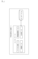
- FIG. 1 is a block diagram showing a schematic configuration of a malfunction location output device according to an embodiment of the present invention.
- FIG. 2 is a diagram showing an example to which the malfunction location output device according to the present embodiment is applied. It is a figure which shows an example of the output result of a defective location based on this embodiment. It is a flowchart figure showing an example of the procedure of the learning method of the machine learning model concerning this embodiment. It is a flowchart figure which shows an example of the procedure of the defective part output method based on this embodiment. It is a flowchart figure which shows an example of the procedure of the defective part output method based on this embodiment.
- FIG. 1 is a block diagram showing a schematic configuration of a malfunction location output device according to an embodiment of the present invention.
- the failure location output device 1 is applied to a system that creates mesh data used in CAE (Computer Aided Engineering) analysis.
- CAE analysis structural mechanics, fluid dynamics, and other analyzes are performed on mesh data created by converting design shape data of an object to be analyzed.
- the design shape data of the object to be analyzed is three-dimensional shape data created using software such as CAD.
- Mesh data is data created by dividing three-dimensional shape data into a grid. That is, mesh data is data in which the design shape of an object to be analyzed is expressed by a mesh.
- the mesh data includes data on nodes and links that make up the mesh.
- each node includes data on a node number and coordinates.
- the coordinates of a node are coordinates that indicate the position of the node in three-dimensional space.
- Link data is data about connection relationships between nodes.
- a plurality of nodes are connected to form a triangle or quadrilateral.
- the mesh data is converted from the three-dimensional shape data of the object to be analyzed using existing automatic meshing software functions.
- mesh data created using existing automatic meshing software functions had defects that required correction. Therefore, it was necessary for a human to visually check the three-dimensional model based on the mesh data displayed on the display to identify and correct defective parts, making it impossible to make corrections efficiently.
- the defective location output device 1 can efficiently correct mesh data by automatically detecting and outputting defective locations in mesh data.
- FIG. 2 is a diagram showing an example to which the malfunction location output device according to the present embodiment is applied.
- FIG. 2(a) shows an example of a three-dimensional model based on three-dimensional shape data to be analyzed by CAE. Three-dimensional shape data as shown in FIG. 2(a) is created using software such as CAD.
- FIG. 2(b) shows an example of a three-dimensional model based on mesh data converted from three-dimensional shape data. Mesh data as shown in FIG. 2(b) is created by an automatic meshing software function or the like.
- FIG. 2(c) shows defect points P1 and P2 occurring in the three-dimensional model based on the mesh data shown in FIG. 2(b).
- the defective location output device 1 automatically detects defective locations such as defective locations P1 and P2 and outputs them to the operator.
- mesh data For example, when analyzing structures made up of multiple parts, such as automobiles. Since it is an assembled structure, there are many fillets and beads, which causes many defects in the mesh data. Problems that occur in mesh data include, for example, in 3D shape data, parts that are ridgelines are not ridgelines, and in 3D shape data, parts that are fillets or beads are distorted. , problems at the merging section, etc.
- the malfunction location output device 1 includes a controller 10 and a database 2.
- the controller 10 includes a computer having hardware and software, and this computer includes a ROM that stores a program, a CPU that executes the program stored in the ROM, and a RAM that functions as an accessible storage device. .
- ROM that stores a program
- CPU that executes the program stored in the ROM
- RAM that functions as an accessible storage device.
- an MPU, DSP, ASIC, FPGA, etc. can be used in place of or in addition to the CPU.
- the controller 10 uses the trained model to detect a defective part by estimating the part or position of the defective part of the mesh data, and outputs the detected defective part.
- the controller 10 includes, as functional blocks, a data input section 11, a feature value calculation section 12, a learning section 13, and an output section 14, and has functions for realizing each of the above functions or executing each process. Each function is executed through cooperation between software and hardware.
- the functions of the controller 10 are divided into four blocks, and the functions of each functional block will be explained.
- the functions of the controller 10 do not necessarily need to be divided into four blocks, and can be divided into three or less blocks. It may be divided into functional blocks or five or more functional blocks.
- the data input unit 11 acquires input data input by an operator.
- Three-dimensional shape data of the object to be analyzed is input to the data input unit 11 as target three-dimensional shape data.
- mesh data corresponding to the target three-dimensional shape data is input to the data input unit 11 as target mesh data.
- the three-dimensional shape data is, for example, CAD data.
- the target mesh data is mesh data in which a defective location has not been identified, and is mesh data that is a target of analysis processing.
- the target mesh data is created by converting the target three-dimensional shape data.
- the data input unit 11 receives learning data for the machine learning model.
- learning mesh data is input to the data input unit 11 .
- the learning mesh data is mesh data in which defective locations have already been identified.
- the learning mesh data is mesh data in which a human visually identified defective locations in the past.
- three-dimensional shape data corresponding to the learning mesh data is input to the data input unit 11 as learning three-dimensional shape data.
- the learning mesh data includes the position of the defective part in the learning mesh data.
- the learning mesh data includes, for each mesh included in the learning mesh data, whether or not there is a defect that requires correction in the mesh. The presence or absence of a defect is expressed as a binary value of 0 or 1. Since the mesh is made up of a plurality of nodes, the position (coordinates) of the node that makes up the defective mesh is identified as the defective location. Furthermore, the learning mesh data includes a portion where there is a defect in the learning mesh data. The parts are classified into, for example, fillet, bead, and no specific part.
- the feature amount calculation unit 12 calculates the feature amount of the mesh data input to the data input unit 11.
- the feature amount calculation unit 12 calculates the feature amount of the target mesh data based on the nodes and links that constitute the target mesh data. For example, the feature amount calculation unit 12 calculates the feature amount of each mesh included in the target mesh data using the coordinates of the nodes forming the mesh and the connection relationship between the nodes.
- the feature amount of the mesh is a value that quantitatively indicates the feature of the mesh.
- the feature amount calculation unit 12 calculates the feature amount of the learning mesh data based on the nodes and links that constitute the learning mesh data. For example, the feature amount calculation unit 12 calculates the feature amount of each mesh included in the learning mesh data.
- the feature amount of the mesh includes the feature amount of the mesh surface and the feature amount around the mesh.
- the feature amount of the mesh surface includes, for example, the attribute value of the mesh surface and the geometric feature amount with respect to other mesh surfaces.
- the attribute values of the mesh surface include the area of the mesh surface, the angle of the mesh surface, and the length of each side of the mesh surface.
- the angles of the mesh surface are, for example, the maximum and minimum internal angles of the mesh surface.
- the attribute value of the mesh surface includes a value indicating the shape of the mesh surface.
- the shape of the mesh surface is either a triangle or a quadrilateral.
- the geometric features with respect to other mesh surfaces include the angle (dihedral angle) between the mesh surface and the other mesh surface, and the distance between the mesh surface and the other mesh surface.
- the feature amount around the mesh includes a geometric feature amount and a statistical feature amount around the mesh.
- the geometric feature around the mesh includes the curvature of the mesh. For example, Gaussian curvature.
- the statistical feature amount around the mesh is the density of the nodes forming the mesh, and the histogram of the normal relationship around the mesh.
- the feature amount calculation unit 12 calculates the feature amount of the three-dimensional shape data input to the data input unit 11.
- the feature amount of the three-dimensional shape data is a value quantitatively indicating the feature of the three-dimensional shape data.
- the feature amount of the three-dimensional shape data includes the geometric feature amount of a surface and an edge line included in the three-dimensional shape data.
- the geometric features of the surface included in the three-dimensional shape data include the area, aspect ratio, volume, and curvature of the surface.
- the geometric feature amount of the edge line included in the three-dimensional shape data includes the curvature and length of the edge line.
- the feature amount of the three-dimensional shape data includes the geometric feature amount of the structure of the three-dimensional shape data.
- the geometric feature amount of the structure of the three-dimensional shape data is, for example, the distance of an R bend included in the three-dimensional shape data.
- the feature amount calculation unit 12 calculates the feature amount of the target three-dimensional shape data.
- the feature amount calculation unit 12 calculates the feature amount of the learning three-dimensional shape data.
- the feature amount calculation unit 12 calculates the feature amount between the mesh data and the three-dimensional shape data corresponding to the mesh data, which are input to the data input unit 11.
- the feature amount between the mesh data and the three-dimensional shape data is, for example, the distance between a mesh included in the mesh data and a corresponding location in the three-dimensional shape data.
- the feature amount calculation unit 12 calculates the feature amount between the target mesh data and the target three-dimensional shape data.
- the feature amount calculation unit 12 calculates the feature amount between the learning mesh data and the learning three-dimensional shape data.
- the learning unit 13 trains a machine learning model using the teacher data to generate a trained model.
- a trained model is a model that has been trained in advance by machine learning so that appropriate output data can be obtained for certain input data.
- the teacher data used in this embodiment is teacher data created based on learning mesh data in which defective locations have already been identified.
- the learning unit 13 associates the learning mesh data input to the data input unit 11 with the feature calculated by the feature calculating unit 12, and determines the position of the defective part in the learning mesh data and the learning mesh.
- Teacher data is generated that is associated with the feature amount of the learning mesh data when a problem occurs in the data.
- the learning unit 13 generates teacher data by associating each node forming the mesh included in the learning mesh data with the feature amount of the mesh.
- the nodes constituting the defective mesh in the learning mesh data (the nodes with defective locations) are associated with the feature amounts of the mesh.
- the node (coordinates) where the defective point is located corresponds to the position where the defective point is located.
- nodes forming a mesh without defects in the learning mesh data are associated with feature amounts of the mesh.
- the learning unit 13 trains the machine learning model using the generated teacher data. Specifically, the learning unit 13 generates training data that associates the position of a defective point in the learning mesh data with the feature amount of the learning mesh data when a defective point occurs in the learning mesh data. Using this method, a machine learning model is trained to generate a trained model for estimating the location of the defective location.
- the learning unit 13 first defines a function indicating an input-output relationship to create a machine learning model.
- a machine learning model is a neural network having a hierarchical structure consisting of an input layer consisting of one or more neurons, an output layer, and at least one intermediate layer.
- the feature amount calculated by the feature amount calculation unit 12 is input to the input layer as input data. For example, the feature amount of each mesh included in the learning mesh data is input.
- the output layer outputs, as output data corresponding to the input data, whether or not there is a defective part for each node. That is, for each node, it is output whether or not there is a defective location. Whether or not there is a defective location is expressed as a binary value of 0 or 1.
- the learning unit 13 uses the machine learning model and the teaching data to minimize the sum of squares of errors between the output value (predicted value) of the machine learning model and the value (correct value) given by the teaching data. , iteratively changes the function. Specifically, the learning unit 13 calculates, for each node, the error between the predicted value output from the machine learning model based on the input data and the correct value of the teacher data, and calculates the error such that the sum of squares of the errors is minimized. Learning is performed by repeatedly updating the coupling coefficients (weights) between each layer of the neural network. The learning unit 13 stores the learned model in the database 2 when the learned model, that is, the learned weight data is output.
- the type of neural network used by the learning unit 13 is not particularly limited, but since a normal neural network would involve a huge number of combinations, this embodiment uses a method called a graph convolutional neural network.
- the nodes and links constituting the mesh included in the mesh data are made into a graph structure, and weights are calculated in each intermediate layer of the neural network using a target node and neighboring nodes near the target node.
- the machine learning model is trained using teacher data based on the feature amount of the learning mesh data, but the present invention is not limited to this.
- the training data used for learning includes, in addition to the feature amounts of the learning mesh data, the feature amounts of the learning three-dimensional shape data, and/or the learning mesh data and the learning three-dimensional shape data. It may be teacher data that associates the feature amount between the positions with the position of the defective part in the learning mesh data. For example, when a problem occurs in the learning mesh data, the learning unit 13 determines the difference between the feature amount of the learning mesh data, the learning mesh data, and the learning three-dimensional shape data corresponding to the learning mesh data.
- the machine learning model is trained by associating the feature amount with the position of the defect in the training mesh data to generate training data, and using the generated training data to train the machine learning model.
- a trained model for estimating the position of a defective part is created using teacher data that associates the position of a defective part in the learning mesh data with the feature amount of the learning mesh data.
- a learned model for estimating the part where the defective part is located is generated using teacher data based on the part where the defective part is located in the learning mesh data. That is, the learning unit 13 generates teacher data by associating a portion of the learning mesh data with a defective location with a feature amount of the learning mesh data when a defective location occurs in the learning mesh data. . Then, the learning unit 13 uses the generated teacher data to train the machine learning model.
- the trained model for estimating the part where the defective part is located is based on the features of the learning mesh data, the features of the learning three-dimensional shape data, and/or the learning mesh data and the learning three-dimensional shape data.
- the feature amount between the original shape data and the original shape data may be generated using teacher data associated with a portion of the learning mesh data that has a defective location.
- the output unit 14 uses the trained model generated by the learning unit 13 to estimate the part or position of the defective part in the target mesh data, and outputs the part or position of the defective part to the operator.
- the output unit 14 inputs the feature amount of the target mesh data as input data to a trained model for estimating a part with a defective part, and outputs the target mesh data from the trained model as output data corresponding to the input data. Outputs the part where the problem is located. For example, when the feature amount for each mesh included in the target mesh data is input as input data, the trained model outputs a portion of the target mesh data where there is a defective point.
- the part is, for example, a fillet, a bead, or no specific part.
- the output unit 14 inputs the feature amount of the target mesh data as input data to a trained model for estimating the position of the defective part, and uses the trained model to determine the position of the defective part in the target mesh data. Output the position.
- the trained model outputs as output data whether or not there is a defective location for each node.
- the output unit 14 detects a defective part by estimating the position where the defective part is located based on the output result of the learned model. Then, the output unit 14 outputs to the operator the coordinates of the node estimated to be the location of the defective location.
- the output unit 14 draws a defective part on a three-dimensional model based on the target mesh data and displays it on the display.
- the output unit 14 displays a node with a defective part in a three-dimensional model based on the target mesh data in a drawing form that is more emphasized than a node without a defective part.
- the emphasized drawing forms include, for example, drawing in different colors and drawing in different shapes.
- FIG. 3 is a diagram illustrating a display example of the output results of defective locations according to the present embodiment.
- a three-dimensional model based on target mesh data is drawn and displayed using nodes that constitute the target mesh data.
- a node with a defective part such as a node P with a defective part, is displayed in a different rendering form from a node without a defective part.
- the output unit 14 uses the feature amount of the target mesh data as input data and uses the learned model to estimate the part or position of the defective part in the target mesh data. Not limited to.
- the output unit 14 uses, as input data, in addition to the feature amount of the target mesh data, the feature amount of the target three-dimensional shape data, and/or the feature amount between the target mesh data and the target three-dimensional shape data,
- the model may be used to estimate a defective part or parts in the target mesh data.
- the output unit 14 first uses the feature amount of the target mesh data as input data and uses the learned model to estimate candidate parts where the defective part is located in the target mesh data. It is also possible to narrow down the candidate areas where there is. After estimating the candidate region, the output unit 14 outputs, in addition to the feature amount of the target mesh data, the feature amount of the target three-dimensional shape data and/or the target mesh data and the target three-dimensional shape data in the candidate region. The position of the defective part in the target mesh data may be estimated by using the feature amount between as input data.
- a machine learning model is used to detect defective locations in target mesh data. As a result, defective locations can be detected more efficiently than an algorithm that uses logic to detect defective locations based on predetermined rules.
- the database 2 stores various data.
- the database 2 stores trained models.
- the database 2 stores a trained model that has been trained to estimate the location of the defective location and a trained model that has been trained to estimate the location of the defective location. ing.
- the database 2 stores input mesh data and three-dimensional shape data. Further, the database 2 stores teacher data for learning the machine learning model.
- the database 2 is a database installed in the failure location output device 1, but is not limited to this, and may be a database external to the failure location output device 1.
- FIG. 4 is a flowchart diagram illustrating an example of a procedure for learning a machine learning model according to the present embodiment.
- the controller 10 acquires input learning data.
- the learning data includes learning mesh data and learning three-dimensional shape data corresponding to the learning mesh data.
- the learning mesh data includes data on the part or position of the defective part.
- the controller 10 calculates feature amounts. For example, the controller 10 calculates the feature amount of the learning mesh data, the feature amount of the learning three-dimensional shape data, and the feature amount between the learning mesh data and the learning three-dimensional shape data.
- step S3 the controller 10 generates teacher data based on the learning data acquired in step S1 and the feature amount calculated in step S2.
- the generated training data is training data used for machine learning to estimate the part where the defective part is located, and training data used for machine learning to estimate the position where the defective part is located.
- the training data used for machine learning to estimate the part with the defective part is the part with the defective part in the learning mesh data, and the characteristics of the learning mesh data when the defective part occurs in the learning mesh data.
- This is teacher data that associates the amount, the feature amount of the learning three-dimensional shape data, and the feature amount between the learning mesh data and the learning three-dimensional shape data.
- the training data used for machine learning to estimate the position of the defective part is the position of the defective part in the learning mesh data, and the learning mesh data when the defective part occurs in the learning mesh data.
- This is teacher data that associates the feature amount of , the feature amount of the learning three-dimensional shape data, and the feature amount between the learning mesh data and the learning three-dimensional shape data.
- step S4 the controller 10 trains the machine learning model using the teacher data generated in step S3. Through machine learning, the controller 10 generates a learned model that has been trained to estimate the position where the defective part is located, and a trained model that has been trained to estimate the part where the defective part is located. In step S5, the controller 10 outputs the trained model trained in step S4.
- the feature values of the learning mesh data, the feature values of the learning 3D shape data, and the feature values between the learning mesh data and the learning 3D shape data are calculated to perform machine learning.
- the present invention is not limited to this, and it is also possible to calculate only the feature amount of the learning mesh data and use it for machine learning.
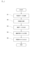
- FIG. 5 is a flowchart illustrating an example of the procedure of the defect location output method according to the present embodiment.
- the controller 10 outputs defective locations using mesh data.
- the controller 10 acquires the input target mesh data.
- the controller 10 calculates the feature amount of the target mesh data.
- step S13 the controller 10 inputs the feature amount calculated in step S12 to the learned model as input data.
- the trained model is the trained model trained in FIG. 4, and is, for example, a trained model for estimating the location of a defective location.
- step S14 the controller 10 uses the trained model to estimate, for each node included in the target mesh data, whether or not there is a defective location.
- step S15 the controller 10 outputs the estimation result estimated in step S14. For example, the controller 10 outputs to the operator the coordinates of the node estimated to be the location of the defective location.
- a trained model for estimating the part where the defective part is located may be used to estimate the part where the defective part is located, and the part where the defective part is located may be output to the operator.
- FIG. 6 is a flowchart illustrating an example of the procedure of the defect location output method according to the present embodiment.
- the controller 10 outputs defective locations using mesh data and three-dimensional shape data.
- step S21 the controller 10 acquires the input target mesh data and target three-dimensional shape data.
- step S22 the controller 10 calculates a feature amount based on the input data acquired in step S21. For example, the controller 10 calculates the feature amount of the target mesh data, the feature amount of the target three-dimensional shape data, and the feature amount between the target mesh data and the target three-dimensional shape data.
- step S23 the controller 10 inputs the feature amount calculated in step S22 to the learned model as input data.
- step S24 the controller 10 uses the learned model to estimate, for each node of the target mesh data, whether or not there is a defective location.
- step S25 the controller 10 outputs the estimation result estimated in step S24. For example, the controller 10 outputs to the operator the coordinates of the node estimated to be the location of the defective location.
- a trained model for estimating the part where the defective part is located may be used to estimate the part where the defective part is located, and the part where the defective part is located may be output to the operator.
- the controller calculates the feature amount of the target mesh data based on the nodes and links that constitute the target mesh data that is the target of analysis processing created by converting the three-dimensional shape data.
- the trained model inputs the feature values of the target mesh data as input data, uses the trained model to output the parts or positions where there are defects that need to be corrected in the target mesh data, and the trained model , training data that associates the part or position of the defective point in the learning mesh data in which the defective point has already been identified with the feature amount of the learning mesh data when the defective point has occurred in the learning mesh data. Learning is being done using. Thereby, the three-dimensional model for analysis can be efficiently modified.
- the controller determines the characteristics between the target mesh data and the target three-dimensional shape data based on the nodes and links that constitute the target mesh data and the target three-dimensional shape data corresponding to the target mesh data. Calculate the amount, input the feature values between the target mesh data and the target 3D shape data into the trained model as input data, and use the trained model to identify the parts of the target mesh data that have defects that require correction. Or output the position, and the trained model corresponds to the part or position of the defective part in the learning mesh data and the learning mesh data and the learning mesh data when the defective part occurs in the learning mesh data. Learning is performed using teacher data that associates features between three-dimensional shape data for learning. Thereby, the three-dimensional model for analysis can be modified more accurately and efficiently.
- the controller inputs the feature values of the target mesh data to the trained model as input data, and uses the trained model to output candidate parts that have defective parts that need to be corrected in the target mesh data. Then, input the feature amount of the target mesh data and the feature amount between the target mesh data and the target three-dimensional shape data in the candidate region to the trained model as input data, and use the trained model to calculate the target mesh. Outputs the location of the defective part in the data that requires correction. Thereby, the three-dimensional model for analysis can be modified more accurately and efficiently.
- the feature amounts of the target mesh data and the learning mesh data include the feature amount of the mesh surface of the mesh included in each mesh data and the feature amount of the mesh periphery.
- the feature amount between the target mesh data and the target three-dimensional shape data is the distance between the mesh included in the target mesh data and the corresponding location in the target three-dimensional shape data.
Landscapes
- Engineering & Computer Science (AREA)
- Physics & Mathematics (AREA)
- Theoretical Computer Science (AREA)
- Software Systems (AREA)
- General Physics & Mathematics (AREA)
- General Engineering & Computer Science (AREA)
- Evolutionary Computation (AREA)
- Geometry (AREA)
- Artificial Intelligence (AREA)
- Computer Graphics (AREA)
- Computer Hardware Design (AREA)
- Computer Vision & Pattern Recognition (AREA)
- Data Mining & Analysis (AREA)
- Medical Informatics (AREA)
- Mathematical Physics (AREA)
- Computing Systems (AREA)
- Computational Linguistics (AREA)
- Biophysics (AREA)
- Architecture (AREA)
- Biomedical Technology (AREA)
- General Health & Medical Sciences (AREA)
- Molecular Biology (AREA)
- Life Sciences & Earth Sciences (AREA)
- Health & Medical Sciences (AREA)
- Image Analysis (AREA)
- Length Measuring Devices With Unspecified Measuring Means (AREA)
Priority Applications (4)
| Application Number | Priority Date | Filing Date | Title |
|---|---|---|---|
| EP22953380.7A EP4571600A4 (en) | 2022-08-09 | 2022-08-09 | DEFECTIVE LOCATION EXIT METHOD AND DEFECTIVE LOCATION EXIT DEVICE |
| PCT/JP2022/030418 WO2024034010A1 (ja) | 2022-08-09 | 2022-08-09 | 不具合箇所出力方法及び不具合箇所出力装置 |
| CN202280098839.6A CN119654638A (zh) | 2022-08-09 | 2022-08-09 | 瑕疵部分输出方法和瑕疵部分输出装置 |
| JP2024540116A JPWO2024034010A1 (https=) | 2022-08-09 | 2022-08-09 |
Applications Claiming Priority (1)
| Application Number | Priority Date | Filing Date | Title |
|---|---|---|---|
| PCT/JP2022/030418 WO2024034010A1 (ja) | 2022-08-09 | 2022-08-09 | 不具合箇所出力方法及び不具合箇所出力装置 |
Publications (1)
| Publication Number | Publication Date |
|---|---|
| WO2024034010A1 true WO2024034010A1 (ja) | 2024-02-15 |
Family
ID=89851208
Family Applications (1)
| Application Number | Title | Priority Date | Filing Date |
|---|---|---|---|
| PCT/JP2022/030418 Ceased WO2024034010A1 (ja) | 2022-08-09 | 2022-08-09 | 不具合箇所出力方法及び不具合箇所出力装置 |
Country Status (4)
| Country | Link |
|---|---|
| EP (1) | EP4571600A4 (https=) |
| JP (1) | JPWO2024034010A1 (https=) |
| CN (1) | CN119654638A (https=) |
| WO (1) | WO2024034010A1 (https=) |
Cited By (2)
| Publication number | Priority date | Publication date | Assignee | Title |
|---|---|---|---|---|
| JP7745807B1 (ja) * | 2024-08-08 | 2025-09-29 | 三菱電機株式会社 | 学習装置、推論装置、プログラム、学習方法及び推論方法 |
| WO2026033874A1 (ja) * | 2024-08-08 | 2026-02-12 | 三菱電機株式会社 | 学習装置、推論装置、プログラム、学習方法及び推論方法 |
Citations (4)
| Publication number | Priority date | Publication date | Assignee | Title |
|---|---|---|---|---|
| JP2004094663A (ja) | 2002-08-30 | 2004-03-25 | Fujitsu Ltd | 変換チェック装置、変換チェック方法、プログラム及び記憶媒体 |
| JP2006318232A (ja) * | 2005-05-12 | 2006-11-24 | Fuji Heavy Ind Ltd | 解析用メッシュ修正装置 |
| JP2019003324A (ja) * | 2017-06-13 | 2019-01-10 | トヨタ自動車株式会社 | Cae解析支援装置 |
| CN113221403A (zh) * | 2021-04-28 | 2021-08-06 | 中汽数据(天津)有限公司 | 基于深度强化学习的有限元网格优化方法、设备和介质 |
Family Cites Families (1)
| Publication number | Priority date | Publication date | Assignee | Title |
|---|---|---|---|---|
| US20220215145A1 (en) * | 2019-05-22 | 2022-07-07 | Xitadel Cae Technologies India Pvt. Ltd. | Machine learning for rapid automatic computer-aided engineering modeling |
-
2022
- 2022-08-09 WO PCT/JP2022/030418 patent/WO2024034010A1/ja not_active Ceased
- 2022-08-09 EP EP22953380.7A patent/EP4571600A4/en not_active Withdrawn
- 2022-08-09 JP JP2024540116A patent/JPWO2024034010A1/ja active Pending
- 2022-08-09 CN CN202280098839.6A patent/CN119654638A/zh active Pending
Patent Citations (4)
| Publication number | Priority date | Publication date | Assignee | Title |
|---|---|---|---|---|
| JP2004094663A (ja) | 2002-08-30 | 2004-03-25 | Fujitsu Ltd | 変換チェック装置、変換チェック方法、プログラム及び記憶媒体 |
| JP2006318232A (ja) * | 2005-05-12 | 2006-11-24 | Fuji Heavy Ind Ltd | 解析用メッシュ修正装置 |
| JP2019003324A (ja) * | 2017-06-13 | 2019-01-10 | トヨタ自動車株式会社 | Cae解析支援装置 |
| CN113221403A (zh) * | 2021-04-28 | 2021-08-06 | 中汽数据(天津)有限公司 | 基于深度强化学习的有限元网格优化方法、设备和介质 |
Non-Patent Citations (1)
| Title |
|---|
| See also references of EP4571600A4 |
Cited By (2)
| Publication number | Priority date | Publication date | Assignee | Title |
|---|---|---|---|---|
| JP7745807B1 (ja) * | 2024-08-08 | 2025-09-29 | 三菱電機株式会社 | 学習装置、推論装置、プログラム、学習方法及び推論方法 |
| WO2026033874A1 (ja) * | 2024-08-08 | 2026-02-12 | 三菱電機株式会社 | 学習装置、推論装置、プログラム、学習方法及び推論方法 |
Also Published As
| Publication number | Publication date |
|---|---|
| CN119654638A (zh) | 2025-03-18 |
| EP4571600A1 (en) | 2025-06-18 |
| EP4571600A4 (en) | 2025-09-24 |
| JPWO2024034010A1 (https=) | 2024-02-15 |
Similar Documents
| Publication | Publication Date | Title |
|---|---|---|
| CN110059330B (zh) | 用于创作模拟场景的方法和系统 | |
| TWI737077B (zh) | 用於驗證積體電路佈局的電腦實施的方法 | |
| US10289770B2 (en) | Rotorcraft component simulation using scan-based geometry | |
| WO2024034010A1 (ja) | 不具合箇所出力方法及び不具合箇所出力装置 | |
| CN120355106B (zh) | 一种基于大模型的bim模型结构设计审查方法及系统 | |
| CN108664686A (zh) | 用于设计模面的方法 | |
| CN104951350A (zh) | 航天产品总装工艺仿真分析方法 | |
| CN110009742B (zh) | 用于有限元素网格修复的系统和方法 | |
| CN120953334A (zh) | 基于bim的建筑工程数据处理方法及系统 | |
| JP2011194472A (ja) | プレス加工された板金部品の表面欠陥を数値的に予測する方法およびシステム | |
| CN110334450B (zh) | 一种多块结构网格生成中物面投影错误的修复方法 | |
| JP7407648B2 (ja) | 物体認識装置及び物体認識方法 | |
| CN116894814A (zh) | 基于无锚框目标检测的焊缝缺陷检测方法、系统和介质 | |
| JP7360016B2 (ja) | データ処理方法、データ処理装置、及びプログラム | |
| CN121302690A (zh) | 一种基于参数化设计的cad绘图优化方法 | |
| CN120962435A (zh) | 一种基于机器视觉的放射性大罐智能切割控制方法及系统 | |
| Mostafavi et al. | Performance driven design and design information exchange | |
| CN117171922B (zh) | 一种钢结构制作中平行矫正的方法及系统 | |
| JP2016203216A (ja) | 鍛造型の補正方法 | |
| CN108171435A (zh) | 一种考虑预防性维护的生产计划决策方法 | |
| CN113984416A (zh) | 转向架的检测数据处理方法、装置、设备及可读存储介质 | |
| JP6086793B2 (ja) | タイヤ摩耗シミュレーション方法及びタイヤ摩耗シミュレーションプログラム | |
| CN117807684A (zh) | 一种基于三维建模软件的钢箱梁参数化建模方法及系统 | |
| Gerschütz et al. | Enabling Initial Design-Checks of Parametric Designs Using Digital Engineering Methods | |
| CN118313070B (zh) | 一种基于深度学习的汽车结构受力异常分析方法及系统 |
Legal Events
| Date | Code | Title | Description |
|---|---|---|---|
| 121 | Ep: the epo has been informed by wipo that ep was designated in this application |
Ref document number: 22953380 Country of ref document: EP Kind code of ref document: A1 |
|
| WWE | Wipo information: entry into national phase |
Ref document number: 2024540116 Country of ref document: JP |
|
| WWE | Wipo information: entry into national phase |
Ref document number: 202280098839.6 Country of ref document: CN |
|
| WWE | Wipo information: entry into national phase |
Ref document number: 2022953380 Country of ref document: EP |
|
| NENP | Non-entry into the national phase |
Ref country code: DE |
|
| ENP | Entry into the national phase |
Ref document number: 2022953380 Country of ref document: EP Effective date: 20250310 |
|
| WWP | Wipo information: published in national office |
Ref document number: 202280098839.6 Country of ref document: CN |
|
| WWP | Wipo information: published in national office |
Ref document number: 2022953380 Country of ref document: EP |
|
| WWW | Wipo information: withdrawn in national office |
Ref document number: 2022953380 Country of ref document: EP |