WO2024029498A1 - 接合体、摩擦攪拌点接合方法および摩擦攪拌点接合装置 - Google Patents
接合体、摩擦攪拌点接合方法および摩擦攪拌点接合装置 Download PDFInfo
- Publication number
- WO2024029498A1 WO2024029498A1 PCT/JP2023/027992 JP2023027992W WO2024029498A1 WO 2024029498 A1 WO2024029498 A1 WO 2024029498A1 JP 2023027992 W JP2023027992 W JP 2023027992W WO 2024029498 A1 WO2024029498 A1 WO 2024029498A1
- Authority
- WO
- WIPO (PCT)
- Prior art keywords
- shoulder
- pin
- joint
- friction stir
- joint bottom
- Prior art date
- Legal status (The legal status is an assumption and is not a legal conclusion. Google has not performed a legal analysis and makes no representation as to the accuracy of the status listed.)
- Ceased
Links
Images








Classifications
-
- B—PERFORMING OPERATIONS; TRANSPORTING
- B23—MACHINE TOOLS; METAL-WORKING NOT OTHERWISE PROVIDED FOR
- B23K—SOLDERING OR UNSOLDERING; WELDING; CLADDING OR PLATING BY SOLDERING OR WELDING; CUTTING BY APPLYING HEAT LOCALLY, e.g. FLAME CUTTING; WORKING BY LASER BEAM
- B23K20/00—Non-electric welding by applying impact or other pressure, with or without the application of heat, e.g. cladding or plating
- B23K20/12—Non-electric welding by applying impact or other pressure, with or without the application of heat, e.g. cladding or plating the heat being generated by friction; Friction welding
-
- B—PERFORMING OPERATIONS; TRANSPORTING
- B23—MACHINE TOOLS; METAL-WORKING NOT OTHERWISE PROVIDED FOR
- B23K—SOLDERING OR UNSOLDERING; WELDING; CLADDING OR PLATING BY SOLDERING OR WELDING; CUTTING BY APPLYING HEAT LOCALLY, e.g. FLAME CUTTING; WORKING BY LASER BEAM
- B23K20/00—Non-electric welding by applying impact or other pressure, with or without the application of heat, e.g. cladding or plating
- B23K20/12—Non-electric welding by applying impact or other pressure, with or without the application of heat, e.g. cladding or plating the heat being generated by friction; Friction welding
- B23K20/122—Non-electric welding by applying impact or other pressure, with or without the application of heat, e.g. cladding or plating the heat being generated by friction; Friction welding using a non-consumable tool, e.g. friction stir welding
- B23K20/1225—Particular aspects of welding with a non-consumable tool
-
- B—PERFORMING OPERATIONS; TRANSPORTING
- B23—MACHINE TOOLS; METAL-WORKING NOT OTHERWISE PROVIDED FOR
- B23K—SOLDERING OR UNSOLDERING; WELDING; CLADDING OR PLATING BY SOLDERING OR WELDING; CUTTING BY APPLYING HEAT LOCALLY, e.g. FLAME CUTTING; WORKING BY LASER BEAM
- B23K20/00—Non-electric welding by applying impact or other pressure, with or without the application of heat, e.g. cladding or plating
- B23K20/12—Non-electric welding by applying impact or other pressure, with or without the application of heat, e.g. cladding or plating the heat being generated by friction; Friction welding
- B23K20/122—Non-electric welding by applying impact or other pressure, with or without the application of heat, e.g. cladding or plating the heat being generated by friction; Friction welding using a non-consumable tool, e.g. friction stir welding
- B23K20/123—Controlling or monitoring the welding process
Definitions
- the present disclosure relates to a joined body in which a plurality of metal members are joined, a friction stir point welding method for joining a plurality of metal members, and a friction stir point welding device.
- a joined body in which a plurality of metal members are joined is sometimes used as a component of a structure such as an aircraft, a railway vehicle, or an automobile.
- a friction stir spot welding method is known as one of such joining methods.
- Patent Document 1 discloses forming a joined body by friction stir point welding three metal members using a double-acting rotary tool equipped with a coaxially arranged probe, an inner shoulder member, and an outer shoulder member.
- a bonding method is disclosed.
- the inner shoulder member has a cylindrical shape that encloses the cylindrical probe
- the outer shoulder member has a cylindrical shape that encloses the inner shoulder member.
- a probe and an inner shoulder member are placed in front of the overlapping portion of three metal members to be point-joined, with their tip surfaces flush with each other, until they reach the vicinity of the interface between the first and second metal members.
- Stir welding in which three metal members are point-welded to the overlapped portion by press-fitting and performing friction stirring, and by making the probe protrude from the inner shoulder member and further press-fitting to the vicinity of the interface between the second and third metal members. part is formed.
- An object of the present disclosure is to provide a joined body, a friction stir point welding method, and a friction stir point welding device that can reduce the occurrence of unstable interfacial fracture and control the fracture mode to plug fracture. .
- a joined body includes a first member made of metal and having a first surface and a first back surface, and a second member made of metal and having a second surface and a second back surface, the second member being made of metal and having a second surface and a second back surface.
- a second member arranged such that at least a portion of a second surface abuts the first back surface and forms an overlapping portion where the first member and the second member overlap; and a joint portion where the members are joined by friction stir welding.
- the joint portion includes a joint bottom surface that is a ring-shaped interface between the first member and the second member that occurs at a position deeper than the second surface with respect to the first surface, and a radially inner side of the joint bottom surface.
- a part of the second member has an inner raised part raised to a position higher than the second surface with respect to the joint bottom surface, and a part of the second member has a raised part on the radially outer side of the joint bottom surface. an outer raised part raised to a position higher than the second surface with respect to the joint bottom surface; It has a recessed part.
- a first member which is made of metal and has a first surface and a first back surface
- a second member which has a second surface and a second back surface
- the friction stir point welding method includes preparing a friction stir point welding device including a pin and a cylindrical shoulder having a hollow portion into which the pin is inserted, and at least a portion of the second surface is connected to the first back surface.
- the first member and the second member are arranged so as to form an overlapping part in which the first member and the second member overlap each other, and the pin and the shoulder are arranged to face the overlapping part.
- the shoulder and the pin form a recessed part that is arranged opposite to the joint bottom surface in the overlapping direction of the first member and the second member and in which a part of the first surface is recessed, and the joint bottom surface and the Along with the formation of the recessed part, a part of the second member forms an inner raised part on the radially inner side of the joint bottom surface that is raised to a position higher than the second surface with the joint bottom surface as a reference; A part of the second member is formed on the radially outer side of the joint bottom surface to form an outer protuberance that is raised to a position higher than the second surface with respect to the joint bottom surface.
- a friction stir spot welding device includes a friction stir spot welding device that frictionally connects a first member having a first surface and a first back surface and a second member having a second surface and a second back surface, each of which is made of metal.
- This is a friction stir point welding device that joins by softening with heat.
- the friction stir spot welding device includes a welding tool including a pin having a central axis and a cylindrical shoulder having a hollow portion into which the pin is inserted, and a rotation mechanism capable of rotating the welding tool about the central axis.
- a mechanism a movement mechanism capable of independently moving the pin and the shoulder in a direction in which the central axis extends, and a control section that controls the rotation mechanism and the movement mechanism, respectively.
- the control unit is configured such that the first member and the second member form an overlapping portion in which at least a portion of the second surface abuts the first back surface and the first member and the second member overlap. and in a state where the pin and the shoulder are arranged opposite to the overlapping part, the pin is retracted from the first surface, and the shoulder is set in the overlapping part with reference to the first surface.
- the shoulder is press-fitted to a deeper press-fitting position than the second surface, and the shoulder forms a joint bottom surface that is an interface between the first member and the second member, and further, after the formation of the joint bottom surface, the shoulder is press-fitted into the While retracting from the position, the pin enters the overlapping portion, and the shoulder and the pin form a part of the first surface that is disposed opposite to the joint bottom surface in the overlapping direction of the first member and the second member. furthermore, with the formation of the joint bottom surface and the recessed portion, a part of the second member on the radially inner side of the joint bottom surface is recessed with respect to the joint bottom surface.
- An inner raised part is formed that is raised to a higher position than the surface, and a part of the second member is raised to a higher position than the second surface with respect to the joint bottom surface on the radially outer side of the joint bottom surface.
- the rotating mechanism and the moving mechanism are each controlled to form a raised portion.
- FIG. 1 is a schematic diagram showing the configuration of a friction stir spot welding apparatus according to the present disclosure.
- FIG. 2 is a diagram showing a shoulder advance process in which a shoulder is first press-fitted into an overlapping portion of joining members when a friction stir point joining tool is used.
- FIG. 3 is a diagram showing a process chart of a friction stir spot welding method according to an embodiment of the present disclosure.
- FIG. 4 is a schematic cross-sectional view for explaining an anchor, hooking, and indentation of a joint according to an embodiment of the present disclosure.
- FIG. 5 is a schematic cross-sectional view showing the arrangement of pins and shoulders when forming an indentation of a joined body according to an embodiment of the present disclosure.
- FIG. 1 is a schematic diagram showing the configuration of a friction stir spot welding apparatus according to the present disclosure.
- FIG. 2 is a diagram showing a shoulder advance process in which a shoulder is first press-fitted into an overlapping portion of joining members when a friction stir point joining tool is used
- FIG. 6 is a schematic cross-sectional view for explaining the fracture mode of the joined body.
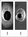
- FIG. 7 is an image of a state in which the upper plate and the lower plate are peeled off when interfacial fracture occurs in the bonded body.
- FIG. 8 is an image of a state in which the upper plate and the lower plate are peeled off when a plug fracture occurs in the joined body.
- FIG. 9 is a graph showing the relationship between welding time and shoulder depression amount in the friction stir point welding method according to an embodiment of the present disclosure.
- FIG. 10 is a graph showing the relationship between anchor height and tensile strength in a joined body according to the present disclosure.
- FIG. 11 is a graph showing the relationship between anchor height and fracture mode in a joined body according to the present disclosure.
- FIG. 12 is a graph showing the relationship between hooking height and fracture mode in a joined body according to the present disclosure.
- FIG. 13 is a graph showing the relationship between the amount of shoulder press-fit into the lower plate and the anchor height in the joined body according to the present disclosure.
- FIG. 14 is a graph showing the relationship between the amount of shoulder press-fit into the lower plate and the hooking height in the joined body according to the present disclosure.
- FIG. 15 is a cross-sectional image showing the anchor height and hooking height when the shoulder press-fit amount is changed in the joined body according to the present disclosure.
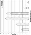
- FIG. 16 is a graph showing the relationship between effective distance and fracture mode in the joined body according to the present disclosure.
- FIG. 17 is a graph showing the relationship between displacement and load when a tensile shear test is performed on the joined body.
- FIG. 18 is a cross-sectional image showing a fractured state of the bonded body corresponding to the graph shown in FIG. 17.
- FIG. 19 is a graph showing the relationship between anchor height and fracture mode in a joined body according to the present disclosure.
- the friction stir spot welding method according to the present disclosure can be applied to the production of various joined bodies made by overlapping and spot-welding two or more structural materials such as metal plates, frames, exterior materials, or columnar materials. can.
- the manufactured joined body becomes, for example, a component of a structure such as an aircraft, a railway vehicle, or an automobile.
- FIG. 1 is a schematic diagram showing the configuration of a friction stir spot welding apparatus M according to an embodiment of the present disclosure.
- the friction stir spot welding device M joins the upper plate 31 and the lower plate 32 by softening them with frictional heat.
- the friction stir spot welding apparatus M includes a tool 1 for friction stir spot welding, a tool drive unit 2 that rotates and drives the tool 1 to move up and down, and a controller C that controls the operation of the tool drive unit 2.
- direction indications such as “up” and “down” are shown in FIG. 1, this is for convenience of explanation and is not intended to limit the direction in which the tool 1 is actually used.
- the tool 1 is supported by the tool fixing part.
- the tool fixing part can be, for example, a tip of an articulated robot.
- a backup 15 is arranged opposite the lower end surface of the tool 1.
- At least two metal members to be welded are arranged between the tool 1 and the backup 15.
- an overlapping portion 30 in which a part of an upper plate 31 made of a flat plate and a part of a lower plate 32 also made of a flat plate overlap in the vertical direction is arranged between the tool 1 and the backup 15.
- An example is shown below. Note that the tool 1 corresponds to the joining tool of the present disclosure.
- the tool 1 includes a pin 11 extending along a predetermined axial direction, a shoulder 12, a clamp 13, and a spring 14.
- the pin 11 is formed in a cylindrical shape and is arranged so that its central axis extends in the vertical direction.
- the pin 11 is rotatable about the axis R, and can move up and down, that is, move back and forth along the rotation axis R. Note that when the tool 1 is used, the rotation axis R and the point joining position W in the overlapping portion 30 are aligned.
- the tool 1 is a double-acting tool in which a pin 11 and a shoulder 12 move independently.
- the shoulder 12 is a cylindrical member having a hollow portion into which the pin 11 is inserted.
- the axis of the shoulder 12 is coaxial with the axis of the pin 11, which is the rotation axis R.
- the shoulder 12 rotates around the rotation axis R, and moves up and down, that is, advances and retreats along the rotation axis R.
- the shoulder 12 and the pin 11 inserted into the hollow portion both rotate around the rotation axis R and move relative to each other in the direction of the rotation axis R. In other words, the pin 11 and the shoulder 12 not only move up and down simultaneously along the rotation axis R, but also move independently, with one going down and the other going up.
- the clamp 13 is a cylindrical member that includes a hollow portion into which the shoulder 12 is inserted.
- the axial center of the clamp 13 is also coaxial with the rotation axis R.
- the clamp 13 does not rotate around the axis, but moves up and down, that is, moves forward and backward along the rotation axis R.
- the clamp 13 serves to surround the outer periphery of the pin 11 or the shoulder 12 when they perform friction stirring. The enclosure of the clamp 13 prevents the friction stir material from scattering and allows the friction stir point joining portion to be finished smoothly.
- the spring 14 is attached to the upper end side of the clamp 13 and biases the clamp 13 downward, which is the direction toward the overlapped portion 30.
- the clamp 13 is attached to the tool fixing part via a spring 14.
- the backup 15 includes a support surface 15A (FIG. 1) that supports the lower surface side of the object to be joined (overlapping portion 30).
- the backup 15 is a backing member that supports the overlapping portion 30 when the pin 11 or the shoulder 12 is press-fitted into the overlapping portion 30.
- the clamp 13 biased by the spring 14 presses the overlapped portion 30 against the backup 15.
- the tool drive section 2 includes a rotation drive section 21, a pin drive section 22, a shoulder drive section 23, and a clamp drive section 24.
- the rotation drive unit 21 includes a motor, a drive gear, and the like, and rotates the pin 11 and the shoulder 12 around the rotation axis R.
- the rotation drive unit 21 corresponds to the rotation mechanism of the present disclosure.
- the pin drive unit 22 is a mechanism that moves the pin 11 forward and backward along the rotation axis R, that is, raises and lowers it.
- the pin driving unit 22 drives the pin 11 so that the pin 11 is press-fitted into the overlapping portion 30 and retracted from the overlapping portion 30 .
- the shoulder drive unit 23 is a mechanism that moves the shoulder 12 forward and backward along the rotation axis R, and causes the shoulder 12 to be press-fitted into the overlapping portion 30 and retracted.
- the pin drive unit 22 and the shoulder drive unit 23 correspond to a moving mechanism of the present disclosure that can independently move the pin 11 and the shoulder 12 in the axial direction in which the central axis extends.
- the clamp drive unit 24 is a mechanism that moves the clamp 13 forward and backward along the rotation axis R. The clamp drive unit 24 moves the clamp 13 toward the overlapping portion 30 and presses the overlapping portion 30 against the backup 15. At this time, the urging force of the spring 14 acts.
- the controller C is composed of a microcomputer or the like, and controls the operation of each part of the tool driving section 2 by executing a predetermined control program. Specifically, the controller C controls the rotation drive unit 21 to cause the pin 11 and the shoulder 12 to perform a required rotation operation. Further, the controller C controls the pin drive unit 22, the shoulder drive unit 23, and the clamp drive unit 24 to cause the pin 11, the shoulder 12, and the clamp 13 to perform required forward and backward movement operations. Controller C corresponds to the control unit of the present disclosure.
- the method of using the friction stir spot welding apparatus M is roughly divided into a pin advance process in which the pin 11 of the tool 1 is first press-fitted into the overlapping part of the joining members, and a shoulder 12 is first pressed into the overlapping part of the joining members.
- a shoulder advance process that involves press-fitting.
- the shoulder preceding process is adopted in this embodiment.
- FIG. 2 is a diagram showing processes P11 to P14 of the friction stir point welding method using the shoulder preceding process.
- FIG. 3 is a diagram showing a process chart of the friction stir spot welding method according to the present embodiment.
- FIG. 3 schematically shows a process in which the overlapping portion 30 of the upper plate 31 and the lower plate 32 is friction stir spot welded.
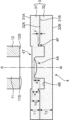
- FIG. 4 is a schematic cross-sectional view for explaining the anchor, hooking, and indentation of the joined body 3 according to this embodiment.
- the upper plate 31 is made of metal and has an upper plate surface 31A and an upper plate back surface 31B (FIG. 1).
- the upper plate surface 31A is the surface of the upper plate 31, and corresponds to the upper surface of the upper plate 31 in FIG.
- the upper plate back surface 31B is the back surface of the upper plate 31, and corresponds to the lower surface of the upper plate 31 in FIG.
- the top plate surface 31A corresponds to the first surface of the present disclosure
- the top plate back surface 31B corresponds to the first back surface of the present disclosure.
- the upper plate 31 is made of an aluminum alloy.
- the upper plate 31 may be made of wrought material or cast metal. Further, the upper plate 31 may be subjected to chemical conversion treatment, electrodeposition coating, or the like.
- the lower plate 32 is made of metal and has a lower plate surface 32A and a lower plate back surface 32B (FIG. 1).
- the lower plate surface 32A is the surface of the lower plate 32, and corresponds to the upper surface of the lower plate 32 in FIG.
- the lower plate back surface 32B is the back surface of the lower plate 32, and corresponds to the lower surface of the lower plate 32 in FIG.
- the lower plate surface 32A corresponds to the second surface of the present disclosure
- the lower plate back surface 32B corresponds to the second back surface of the present disclosure.
- the lower plate 32 is made of high tensile strength steel.
- the lower plate 32 may be made of mild steel or hot stamped steel.
- the lower plate 32 may be subjected to non-plating treatment, zinc plating treatment, Al--Si plating treatment, chemical conversion treatment, electrodeposition coating, etc. Moreover, an adhesive or a sealing material may be interposed between the upper plate 31 and the lower plate 32. Note that, as described above, since the upper plate 31 is made of aluminum alloy and the lower plate 32 is made of high-strength steel, the melting point of the upper plate 31 is set lower than the melting point of the lower plate 32.
- an overlapping portion 30 is formed by the upper plate 31 and the lower plate 32 (step S1 in FIG. 3).
- the overlapping portion 30 at least a portion of the lower plate surface 32A abuts the upper plate back surface 31B, and the upper plate 31 and the lower plate 32 are arranged to overlap.
- the tool 1 is placed in a predetermined position and rotated (step S2 in FIG. 3). Specifically, first, the tool 1 is placed facing the overlapping portion 30 so that the rotation axis R of the tool 1 is parallel to the overlapping direction of the upper plate 31 and the lower plate 32, that is, the vertical direction. In addition, regarding the mode in which the tools are disposed facing each other, the rotation axis R of the tool 1 may be disposed so as to be inclined with respect to the vertical direction. In this embodiment, the lower end surface of the tool 1 is brought into contact with the upper plate surface 31A of the upper plate 31 with the rotation axis R aligned at a predetermined point joining position W. Further, the clamp 13 presses the overlapping portion 30 against the backup 15 (FIG.
- process P11 in FIG. 2 shows a preheating process for the overlapping portion 30.
- a press-fitting step is performed in which the shoulder 12 is press-fitted into the overlapped portion 30 with the pin 11 retracted from the overlapped portion 30 (process P12 in FIG. 2, step S3 in FIG. 3).
- the controller C controls the shoulder drive unit 23 to lower the shoulder 12 as indicated by the white arrow in process P12 in FIG.
- the pin driving section 22 is controlled to raise the pin 11 as indicated by the white arrow, that is, to retract it.
- the clamp 13 is immovable.
- the shoulder 12 is press-fitted at the overlapped portion 30 to a press-fitting position deeper than the lower plate surface 32A with the upper plate surface 31A as a reference (FIG. 2).
- a joint bottom surface 4B FIG.
- the controller C controls the shoulder drive unit 23 to retract the shoulder 12 from the press-fitting position as indicated by the white arrow in process P13 in FIG. 22 to lower the pin 11 so as to enter the overlapping portion 30 as indicated by the white arrow (process P13 in FIG. 2, step S4 in FIG. 3).
- This process shows a backfilling process for overflowing material OF.
- the controller C controls the shoulder drive section 23 to raise the shoulder 12, and controls the pin drive section 22 to lower the pin 11. By lowering the pin 11, the overflowing material OF that has escaped into the hollow space is filled back into the press-fit area of the shoulder 12, as shown by arrow b2.
- a smoothing process is performed in which the overlapping portion 30 is smoothed out (process P14 in FIG. 2, step S5 in FIG. 3).
- the controller C controls the pin drive unit 22 and the shoulder drive unit 23 to place the lower end surface of the pin 11 and the lower end surface of the shoulder 12 at a position lower than the upper plate surface 31A of the upper plate 31. Rotate both to smooth the point joint. As a result, an indent 4T (FIG. 4), which will be described later, is formed.
- the stirring joint portion 4 (FIG. 1) in which the upper plate 31 and the lower plate 32 are joined is formed.
- the stirring joint section 4 corresponds to the joint section of the present disclosure.
- the stir welded portion 4 of the joined body 3 formed by friction stir spot welding as described above includes a weld bottom surface 4B, an anchor 4A, a hook 4F, and an indent 4T.
- the bonding bottom surface 4B is an interface between the upper plate 31 and the lower plate 32 that is formed at a position deeper than the lower plate surface 32A with respect to the upper plate surface 31A as a result of being pressurized by the shoulder 12.
- the joint bottom surface 4B When viewed along the rotation axis R, the joint bottom surface 4B has a ring shape corresponding to the shoulder lower surface portion 12S of the shoulder 12. Note that the ring shape is not limited to one consisting of two perfect circles, and may have an irregular shape depending on the conditions of friction stir spot welding. In other words, the joint bottom surface 4B has a substantially ring shape in plan view.
- the anchor 4A is a raised portion in which a portion of the lower plate 32 is raised to a higher position than the lower plate surface 32A with the joint bottom surface 4B as a reference, on the radially inner side of the joint bottom surface 4B.
- the anchor 4A is formed by the overflowing material OF overflowing from the overlapping portion 30 into the hollow space of the shoulder 12 in the press-fitting process having its upper end crushed by the pin 11 in the backfilling process.
- Anchor 4A corresponds to the inner ridge of the present disclosure.
- the hooking 4F is a raised portion in which a portion of the lower plate 32 is raised to a higher position than the lower plate surface 32A with the joint bottom surface 4B as a reference on the radially outer side of the joint bottom surface 4B.
- the overflowing material OF of the lower plate 32 overflows into the hollow space of the shoulder 12, but even on the radially outer side of the shoulder 12, a part of the lower plate 32 is caused by the press-fitting of the shoulder 12. It is pushed up and hook 4F is formed. Hooking 4F corresponds to the outer raised portion of the present disclosure.
- the indent 4T is a recessed portion in which a part of the upper plate surface 31A of the upper plate 31 is depressed, and is arranged to face the joint bottom surface 4B and the anchor 4A in the overlapping direction of the upper plate 31 and the lower plate 32, that is, in the vertical direction. corresponds to
- FIG. 5 is a schematic cross-sectional view showing the arrangement of the pins 11 and shoulders 12 when forming the indentation of the joined body 3 according to the present embodiment.
- the shoulder 12 is rotated and evacuated from the press-fitting position, and in the above-mentioned leveling process (process P14 in FIG. 2, step S5 in FIG. 3), as shown in FIG. , the controller C positions the pin lower surface portion 11S of the pin 11 and the shoulder lower surface portion 12S of the shoulder 12 at a position closer to the upper plate back surface 31B than the upper plate surface 31A, so that the indentation can be performed at any position in the stirring joint portion 4. 4T can be formed.
- the shoulder lower surface portion 12S corresponds to the distal end surface of the shoulder 12.
- the controller C of the friction stir spot welding apparatus M controls the tool drive unit 2 to form the anchor 4A, the welding bottom surface 4B, the hooking 4F, and the indent 4T in the stir welding part 4. At the same time, the upper plate 31 and the lower plate 32 are joined.
- the thickness of the upper plate 31 is defined as an upper plate thickness T1
- the thickness of the lower plate 32 is defined as a lower plate thickness T2.
- the distance in the overlapping direction from the top of the hooking 4F to the bottom of the indent 4T is defined as an effective distance K.
- the distance in the overlapping direction from the lower plate surface 32A to the top of the anchor 4A is defined as the anchor height A.
- Anchor height A corresponds to the inner ridge height of the present disclosure.
- the distance in the overlapping direction from the upper plate back surface 31B to the bottom of the indent 4T is defined as a reference distance TS.
- the distance in the overlapping direction from the upper plate back surface 31B to the top of the hooking 4F is defined as the hooking height F.
- the stirring joint portion 4 where the upper plate 31 and the lower plate 32 are joined has a joining bottom surface 4B, an anchor 4A, a hook 4F, and an indent 4T.
- the upper plate 31 is arranged so that a part of the upper plate 31 bites below the upper plate back surface 31B (lower plate surface 32A).
- a part of the lower plate 32 is disposed as an anchor 4A so as to be raised above the upper plate back surface 31B.
- a part of the lower plate 32 is arranged as a hook 4F so as to protrude above the upper plate back surface 31B.
- the upper plate 31 and the lower plate 32 bite into each other, so that the upper plate 31 and the lower plate 32 are firmly joined and their strength can be increased.
- FIG. 6 is a schematic cross-sectional view for explaining the fracture mode of the joined body 3.
- a plug fracture is a fracture that occurs along the overlapping direction of the upper plate 31 and the lower plate 32
- an interface fracture is a fracture that occurs along the interface between the upper plate 31 and the lower plate 32.
- FIG. 7 is an image of the agitation joint 4 with the upper plate 31 and the lower plate 32 peeled off in a case where interfacial fracture is intentionally caused in the joined body 3.
- FIG. 8 is an image of the agitation joint 4 with the upper plate 31 and the lower plate 32 peeled off when plug breakage occurs in the joined body 3.
- the pin lower surface part 11S of the pin 11 and the shoulder lower surface part 12S of the shoulder 12 are located at a position between the upper plate surface 31A and the upper plate back surface 31B, more specifically, It is arranged near the upper plate surface 31A. Therefore, the indent 4T can be reliably and stably formed in the stirring joint portion 4.
- the effective distance K is 77.0% or less of the reference distance TS.
- the effective distance K is 77.0% or less of the reference distance TS.
- the anchor height A is 55.3% or more and less than 100% of the reference distance TS.
- the upper plate 31 and the lower plate 32 can be more firmly joined and their strength can be increased. Further, unstable interfacial fracture at the interface between the upper plate 31 and the lower plate 32 can be further prevented, and stable plug fracture can be obtained.
- the upper plate 31 and the lower plate 32 are each used in which the melting point of the upper plate 31 is lower than that of the lower plate 32.
- a part of the lower plate 32 can bite into the upper plate 31, which has a relatively low melting point, to a higher position by friction stir point welding, so that the anchor 4A and the hook 4F can be formed more stably. be able to.
- FIG. 9 is a graph showing the relationship between welding time and shoulder depression amount in the above experiment.
- the vertical axis in FIG. 9 indicates the amount of shoulder depression, with the position of the upper plate surface 31A of the upper plate 31 being set as zero.
- the actual welding operation starts around 0.5 sec in FIG. .
- FIG. 9 shows data under three conditions in which the height of the anchor 4A is different, and the ratio of the anchor height A to the reference distance TS mentioned above is 55.3%, 75.8%, 95. Results for three conditions of 7% are shown.
- the shoulder 12 is pushed in from the upper plate surface 31A around 1 second after the start of the joining operation, is pushed to the maximum pushing position, that is, the press-fitting position, and then is retreated from the press-fitting position. Then, the above-mentioned leveling process is performed at a position between the upper plate surface 31A and the upper plate back surface 31B, in FIG. We were able to confirm that it was formed.
- FIG. 10 is a graph showing the relationship between the ratio of anchor height A to reference distance TS and tensile strength, based on the results shown in Tables 1 to 5 above.
- the average value of the tensile strength under each A/TS condition is shown as a bar graph, and the variation is shown as an I chart.
- the lower limit of tensile strength is almost constant regardless of the value of A/TS, and even if anchor height A/reference distance TS increases, no significant decrease in strength occurs. This was confirmed.
- FIG. 11 is a graph showing the relationship between the ratio of anchor height A to reference distance TS and fracture mode, based on the results shown in Tables 1 to 5 above.
- the horizontal axis in FIG. 11 indicates the ratio of the anchor height A to the reference distance TS expressed as a percentage, and the vertical axis indicates the number of joints in which the fracture mode was confirmed.
- the ratio of the anchor height A to the upper plate thickness T1 is shown in parentheses. Under the conditions of A/TS of 0 and 34.4, interface rupture occurred in two out of 10 joints, but under each condition of A/TS of 55.3 or more, plug rupture occurred in all of the joints.
- the fracture mode occurring in the stir welded portion 4 could be controlled with high accuracy to the plug fracture.
- the anchor height A is set relatively high, in order to avoid a decrease in the strength of the stir joint 4, it is desirable to set the height A so that the top of the anchor 4A does not reach the indent 4T.
- appropriate anchors 4A and indents 4T can be formed by adjusting the press-fitting position and the final position (leveling-in position) of the shoulder 12, respectively.
- FIG. 12 is a graph showing the relationship between the ratio of the hooking height F to the reference distance TS and the fracture mode.
- the hooking height F expressed as a percentage with respect to the reference distance TS is classified into four levels, and the vertical axis indicates the number of joints in which the fracture mode was confirmed.
- the failure mode at 4 of the 13 joints was interfacial failure, but under each condition where F/TS was 9% or higher, the failure mode that occurred was It was confirmed that all the plugs were broken. Therefore, detailed data of each joint under the condition of F/TS of 0 to 9% is shown in Table 6 below.
- FIG. 13 is a graph showing the relationship between the amount of shoulder press-fit into the lower plate 32 and the anchor height A in each joined body 3. As shown in FIG. 13, it was confirmed that the greater the amount of shoulder press-fitting into the lower plate 32, the greater the height of the anchor 4A, and that there is a linear correlation between the two, increasing to the right.
- FIG. 14 is a graph showing the relationship between the amount of shoulder press-fit into the lower plate 32 and the hooking height F. As shown in FIG. 14, the greater the amount of shoulder press-fit into the lower plate 32, the greater the hooking height F becomes.Although the variation is greater than that of the anchor 4A, the two have a linear correlation that rises to the right. It was confirmed that there is.
- FIG. 15 is a cross-sectional image showing how the anchor 4A and hooking 4F change when the shoulder press-fit amount is changed in each of the above-mentioned joined bodies 3.
- the deeper the joint bottom surface 4B is, in other words, the larger the shoulder press-fit amount, the more the anchor 4A and the hook 4F protrude upward, and the anchor height A and the hook height F decrease. You can see it getting bigger.
- the anchor height A and the hooking height F can be set to the target heights. Note that the anchor height A can be adjusted more finely by arranging the pin 11 and shoulder 12 in the above-mentioned leveling process.
- FIG. 16 is a graph showing the relationship between the ratio of the effective distance K to the reference distance TS and the fracture mode.
- the horizontal axis of FIG. 16 shows the ratio of the effective distance K to the reference distance TS expressed as a percentage, and the vertical axis shows the number of joints in which the fracture mode was confirmed.
- the fracture mode that occurred in all the bonded bodies 3 was plug fracture.
- FIG. 17 is a graph showing the relationship between displacement and load when a tensile shear test based on JIS Z3136 was performed on the joined body 3.
- FIG. 18 is a cross-sectional image showing the fractured state of the bonded body 3 corresponding to numbers 1, 2, and 3 in the graph shown in FIG. 17.
- the joined body 3 was tested by applying a load to the lower plate 32 in the right direction and to the upper plate 31 in the left direction. As shown in FIGS.
- Experimental conditions 2 are as follows.
- FIG. 19 is a graph showing the relationship between the ratio of the anchor height A to the reference distance TS and the fracture mode in each bonded body 3.
- the horizontal axis in FIG. 19 indicates the ratio of the anchor height A to the reference distance TS expressed as a percentage, and the vertical axis indicates the number of joints in which the fracture mode was confirmed. In this evaluation, as shown in FIG. 19, it was confirmed that under the condition of A/TS of 55.6% or more, the fracture mode occurring in the joined body 3 was all plug fracture.
- Table 8 shows the results of evaluating the fracture mode under Experimental Condition 3, which is different from Experimental Conditions 1 and 2 above.
- the outer diameter of the pin 11 4 mm
- the outer diameter of the shoulder 12 7 mm
- the pressure load of the clamp 13 5 kN
- the rotation speed of the tool 1 2000 rpm
- shoulder press-in depth 1.07 mm
- upper plate 31 6000 series aluminum alloy with upper plate thickness T1 of 1.0 mm
- lower plate 32 980 MPa class steel with lower plate thickness T2 of 1.2 mm.
- the fracture mode that occurred was plug fracture in all cases where the tensile strength was 3.35 or more and 3.56 kN. It was confirmed that even under such conditions, the fracture mode could be stably controlled to plug fracture because the stirring joint 4 had the joint bottom surface 4B, the anchor 4A, the hook 4F, and the indent 4T.
- the disclosers of the present disclosure have confirmed that the fracture mode in the bonded body 3 can be controlled to plug fracture in the same manner as described above even under the following conditions.
- Table 9 lists the outer diameters of the pin 11 and shoulder 12 of tool 1, the clamping load, rotation speed, press-fitting pressure, and lower plate press-fit amount as joining conditions, and the material and plate thickness of upper plate 31 and lower plate 32 as plate assembly.
- the upper and lower limits of each are shown.
- the lower plate press-fitting amount corresponds to the depth at which the shoulder 12 is press-fitted into the lower plate 32 based on the lower plate surface 32A.
- the lower limit is indicated as zero, but more specifically, it means a value larger than zero (the same applies to Tables 10 and 11 below).
- the upper plate 31 is manufactured by die casting, so-called die casting. Note that each parameter shown in Table 9 can be independently set between the upper and lower limits. The same applies to subsequent tables.
- Table 10 also shows the outer diameters of the pin 11 and shoulder 12 of the tool 1 as more desirable conditions, the clamp load, rotation speed, press-fit pressure and lower plate press-in amount as the joining conditions, and the upper plate 31 and lower plate as the plate assembly. The upper and lower limits of the material and thickness of the plate 32 are shown.
- Table 11 shows the outer diameters of the pin 11 and shoulder 12 of the tool 1 as more desirable conditions, the clamp load, rotational speed, press-fit pressure and lower plate press-fit amount as the joining conditions, and the upper plate 31 and lower plate 32 as the plate assembly. The upper and lower limits of the material and plate thickness are shown.
- the stirring joint 4 having the joint bottom surface 4B, the anchor 4A, the hook 4F, and the indent 4T promoted plug fracture and was able to reduce the number of interface fractures.
- the stir welded portion 4 did not have the indentation 4T, the number of interfacial fractures relatively increased.
- the stir welding part 4 have an indentation of 4T and by setting the effective distance K to 77.0% or less of the reference distance TS, the fracture mode that occurs is further controlled to plug fracture, thereby reducing the occurrence of interface fracture. I was able to do that.
- plug breakage can be controlled with higher precision in the range shown in Tables 10 and 11.
- plug breakage can be controlled with higher accuracy in the range shown in Table 11.
- the present disclosure is not limited to the above conditions. Even under other conditions, when the stirred joint 4 has the indent 4T, the fracture mode is changed to plug fracture because the stirred joint 4 has the weakest part compared to the case where the stirred joint 4 does not have the indent 4T. can be controlled.
- the joined body 3 the friction stir point welding method, and the friction stir point welding apparatus M according to the present disclosure have been described above, the present disclosure is not limited to the above-mentioned embodiments.
- the following modified embodiments can be taken for the above-mentioned joined body 3 and the like.
- the upper plate 31 and the lower plate 32 are each made of one plate, but the present disclosure is not limited thereto.
- At least one of the upper plate 31 and the lower plate 32 may be composed of a plurality of members arranged to overlap in the overlapping direction.
- the plurality of members may be connected with an adhesive or the like. Even in such a configuration, it is possible to firmly join the upper plate 31 and the lower plate 32, suppress the occurrence of interface fracture, and even if fracture occurs, it is possible to prioritize plug fracture. can.
- a joined body includes a first member made of metal and having a first surface and a first back surface, and a second member made of metal and having a second surface and a second back surface. a second member arranged such that at least a portion of the second surface abuts the first back surface and forms an overlapping portion where the first member and the second member overlap; and the first member. and a joint portion where the second member and the second member are joined by friction stir welding.
- the joint portion includes a joint bottom surface that is a ring-shaped interface between the first member and the second member that occurs at a position deeper than the second surface with respect to the first surface, and a radially inner side of the joint bottom surface.
- a part of the second member has an inner raised part raised to a position higher than the second surface with respect to the joint bottom surface, and a part of the second member has a raised part on the radially outer side of the joint bottom surface. an outer raised part raised to a position higher than the second surface with respect to the joint bottom surface; It has a recessed part.
- the joint portion where the first member and the second member are joined has a joint bottom surface, an inner raised portion, an outer raised portion, and a recessed portion.
- the first member is arranged so that a portion of the first member bites into the bottom surface of the joint to a position deeper than the second surface.
- a part of the second member is disposed as an inner raised portion raised to a position higher than the first back surface.
- a part of the second member is disposed as an outer raised portion to be raised to a higher position than the first back surface.
- the cross section of the first surface becomes discontinuous, and the weakest part is intentionally created between the end (corner) of the recess and the top of the outer protrusion. can be formed. Therefore, even if the bonded part breaks due to some reason, either suddenly or over time, by concentrating stress on the weakest part, priority is given to the occurrence of plug breakage. , the occurrence of interfacial fracture can be suppressed. Furthermore, since the inner protrusion and the outer protrusion each bite into the first member side, unstable interfacial rupture at the interface between the first member and the second member can be prevented and stable plug rupture can be obtained. . Therefore, it is possible to visually confirm the occurrence of a fracture in the joint from the outside, and it is possible to discover and deal with it easily and quickly.
- an effective distance that is a distance in the overlapping direction from the top of the outer protrusion to the bottom of the recessed part is The distance from the first back surface to the bottom of the recess in the overlapping direction is 77.0% or less of the reference distance.
- the inner ridge is a distance in the overlapping direction from the second surface to the top of the inner ridge.
- the part height is 55.3% or more and less than 100% of a reference distance that is a distance in the overlapping direction from the first back surface to the bottom of the recessed part.
- the first member and the second member can be more firmly joined and their strength can be increased. Moreover, unstable interfacial fracture at the interface between the first member and the second member can be further prevented, and stable plug fracture can be obtained.
- the melting point of the first member is lower than the melting point of the second member.
- a part of the second member can bite into the first member having a relatively low melting point to a higher position by friction stir point welding, thereby stabilizing the inner protrusion and the outer protrusion. It can be formed by
- a joined body according to a fifth aspect of the present disclosure is a joined body according to the first to fourth aspects described above, wherein the first member is composed of a plurality of members arranged to overlap in the overlapping direction. ing.
- the first member and the second member can be firmly joined, and the occurrence of interfacial fracture can be suppressed, and even if fracture occurs, priority can be given to plug fracture.
- a first member is made of metal and has a first surface and a first back surface
- a second member has a second surface and a second back surface.
- the friction stir point welding method includes preparing a friction stir point welding device including a pin and a cylindrical shoulder having a hollow portion into which the pin is inserted, and at least a portion of the second surface is connected to the first back surface.
- the first member and the second member are arranged so as to form an overlapping part in which the first member and the second member overlap each other, and the pin and the shoulder are arranged to face the overlapping part.
- the shoulder and the pin form a recessed part that is arranged opposite to the joint bottom surface in the overlapping direction of the first member and the second member and in which a part of the first surface is recessed, and the joint bottom surface and the Along with the formation of the recessed part, a part of the second member forms an inner raised part on the radially inner side of the joint bottom surface that is raised to a position higher than the second surface with the joint bottom surface as a reference; A part of the second member is formed on the radially outer side of the joint bottom surface to form an outer protuberance that is raised to a position higher than the second surface with respect to the joint bottom surface.
- a friction stir point welding method includes, in the friction stir point welding method according to the above-described one aspect, after forming the welding bottom surface, retracting the shoulder from the press-fitting position while rotating the shoulder; The method further includes forming the recessed portion by arranging a tip end surface of the shoulder at a position between the first surface and the first back surface.
- a friction stir spot welding device includes a friction stir spot welding device that frictionally connects a first member having a first surface and a first back surface and a second member having a second surface and a second back surface, each of which is made of metal.
- This is a friction stir point welding device that joins by softening with heat.
- the friction stir spot welding device includes a welding tool including a pin having a central axis and a cylindrical shoulder having a hollow portion into which the pin is inserted, and a rotation mechanism capable of rotating the welding tool about the central axis.
- a mechanism a movement mechanism capable of independently moving the pin and the shoulder in a direction in which the central axis extends, and a control section that controls the rotation mechanism and the movement mechanism, respectively.
- the control unit is configured such that the first member and the second member form an overlapping portion in which at least a portion of the second surface abuts the first back surface and the first member and the second member overlap. and in a state where the pin and the shoulder are arranged opposite to the overlapping part, the pin is retracted from the first surface, and the shoulder is set in the overlapping part with reference to the first surface.
- the shoulder is press-fitted to a deeper press-fitting position than the second surface, and the shoulder forms a joint bottom surface that is an interface between the first member and the second member, and further, after the formation of the joint bottom surface, the shoulder is press-fitted into the While retracting from the position, the pin enters the overlapping portion, and the shoulder and the pin form a part of the first surface that is disposed opposite to the joint bottom surface in the overlapping direction of the first member and the second member. furthermore, with the formation of the joint bottom surface and the recessed portion, a part of the second member on the radially inner side of the joint bottom surface is recessed with respect to the joint bottom surface.
- An inner raised part is formed that is raised to a higher position than the surface, and a part of the second member is raised to a higher position than the second surface with respect to the joint bottom surface on the radially outer side of the joint bottom surface.
- the rotating mechanism and the moving mechanism are each controlled to form a raised portion.
Landscapes
- Engineering & Computer Science (AREA)
- Mechanical Engineering (AREA)
- Pressure Welding/Diffusion-Bonding (AREA)
- Braking Arrangements (AREA)
Priority Applications (2)
| Application Number | Priority Date | Filing Date | Title |
|---|---|---|---|
| GB2501389.7A GB2636506A (en) | 2022-08-04 | 2023-07-31 | Welded body, method for friction stir spot welding, and device for friction stir spot welding |
| JP2024539146A JPWO2024029498A1 (https=) | 2022-08-04 | 2023-07-31 |
Applications Claiming Priority (2)
| Application Number | Priority Date | Filing Date | Title |
|---|---|---|---|
| JP2022124889 | 2022-08-04 | ||
| JP2022-124889 | 2022-08-04 |
Publications (1)
| Publication Number | Publication Date |
|---|---|
| WO2024029498A1 true WO2024029498A1 (ja) | 2024-02-08 |
Family
ID=89849338
Family Applications (1)
| Application Number | Title | Priority Date | Filing Date |
|---|---|---|---|
| PCT/JP2023/027992 Ceased WO2024029498A1 (ja) | 2022-08-04 | 2023-07-31 | 接合体、摩擦攪拌点接合方法および摩擦攪拌点接合装置 |
Country Status (3)
| Country | Link |
|---|---|
| JP (1) | JPWO2024029498A1 (https=) |
| GB (1) | GB2636506A (https=) |
| WO (1) | WO2024029498A1 (https=) |
Citations (5)
| Publication number | Priority date | Publication date | Assignee | Title |
|---|---|---|---|---|
| JP2002144052A (ja) * | 2000-11-10 | 2002-05-21 | Kawasaki Heavy Ind Ltd | 摩擦攪拌接合装置 |
| JP2014024101A (ja) * | 2012-07-27 | 2014-02-06 | Sumitomo Electric Ind Ltd | 回転ツールおよび接合方法 |
| JP2017164788A (ja) * | 2016-03-17 | 2017-09-21 | 川崎重工業株式会社 | 摩擦攪拌点接合方法及び摩擦攪拌点接合装置 |
| WO2020218445A1 (ja) * | 2019-04-24 | 2020-10-29 | 川崎重工業株式会社 | 摩擦攪拌点接合装置及びその運転方法 |
| JP2021030266A (ja) * | 2019-08-23 | 2021-03-01 | オジェギン ウニベルシテシ | キーホールのない摩擦攪拌点接合のための装置及びその方法 |
-
2023
- 2023-07-31 JP JP2024539146A patent/JPWO2024029498A1/ja active Pending
- 2023-07-31 WO PCT/JP2023/027992 patent/WO2024029498A1/ja not_active Ceased
- 2023-07-31 GB GB2501389.7A patent/GB2636506A/en active Pending
Patent Citations (5)
| Publication number | Priority date | Publication date | Assignee | Title |
|---|---|---|---|---|
| JP2002144052A (ja) * | 2000-11-10 | 2002-05-21 | Kawasaki Heavy Ind Ltd | 摩擦攪拌接合装置 |
| JP2014024101A (ja) * | 2012-07-27 | 2014-02-06 | Sumitomo Electric Ind Ltd | 回転ツールおよび接合方法 |
| JP2017164788A (ja) * | 2016-03-17 | 2017-09-21 | 川崎重工業株式会社 | 摩擦攪拌点接合方法及び摩擦攪拌点接合装置 |
| WO2020218445A1 (ja) * | 2019-04-24 | 2020-10-29 | 川崎重工業株式会社 | 摩擦攪拌点接合装置及びその運転方法 |
| JP2021030266A (ja) * | 2019-08-23 | 2021-03-01 | オジェギン ウニベルシテシ | キーホールのない摩擦攪拌点接合のための装置及びその方法 |
Also Published As
| Publication number | Publication date |
|---|---|
| JPWO2024029498A1 (https=) | 2024-02-08 |
| GB202501389D0 (en) | 2025-03-19 |
| GB2636506A (en) | 2025-06-18 |
Similar Documents
| Publication | Publication Date | Title |
|---|---|---|
| US12459052B2 (en) | Methods for friction stir welding involving dissimilar materials | |
| US20090291322A1 (en) | Joined body and process for manufacturing the same | |
| WO2016132768A1 (ja) | 接合方法及び複合圧延材の製造方法 | |
| CN113613822B (zh) | 铝材的点焊方法和铝材 | |
| US11806801B2 (en) | Joining method | |
| US12233950B2 (en) | Joint structure and joining method | |
| Sharma et al. | Friction stir spot welding-process and weld properties: a review | |
| WO2020095483A1 (ja) | 液冷ジャケットの製造方法及び摩擦攪拌接合方法 | |
| CN107186334A (zh) | 用于旋转摩擦冲压的铆钉结构及其铆接钢铝叠层板的方法 | |
| JP2021164943A (ja) | アルミニウム合金板と鋼板の摩擦撹拌接合方法 | |
| US20070280849A1 (en) | Friction stir welding process and structure | |
| US20210053146A1 (en) | Apparatus for and a method of keyhole free friction stir spot welding | |
| CN114406439A (zh) | 一种适用于搅拌摩擦铆焊的爪型铆钉及搅拌摩擦铆焊方法 | |
| JP4998027B2 (ja) | 摩擦点接合方法 | |
| WO2019239623A1 (ja) | 接合方法及び複合圧延材の製造方法 | |
| US20040129762A1 (en) | Rivet with sliding cap for friction stir riveting | |
| WO2024029498A1 (ja) | 接合体、摩擦攪拌点接合方法および摩擦攪拌点接合装置 | |
| CN110814507B (zh) | 一种利用液相挤入消除搅拌摩擦焊根部缺陷的方法 | |
| JP2002283070A (ja) | 異種金属材料の摩擦撹拌接合方法 | |
| Ping et al. | Performance evaluation of modified refill friction stir riveting process on AA7075-T6 stacks with largely unequal thicknesses | |
| KR20220156383A (ko) | 마찰 요소 용접 장치 및 방법 | |
| JP7188121B2 (ja) | 接合装置 | |
| WO2025004829A1 (ja) | 摩擦攪拌点接合方法および摩擦攪拌点接合装置 | |
| WO2025253900A1 (ja) | 摩擦攪拌点接合装置および摩擦攪拌点接合方法 | |
| JP7285556B2 (ja) | キーホールのない摩擦攪拌点接合のための装置及びその方法 |
Legal Events
| Date | Code | Title | Description |
|---|---|---|---|
| 121 | Ep: the epo has been informed by wipo that ep was designated in this application |
Ref document number: 23850052 Country of ref document: EP Kind code of ref document: A1 |
|
| WWE | Wipo information: entry into national phase |
Ref document number: 2024539146 Country of ref document: JP |
|
| ENP | Entry into the national phase |
Ref document number: 202501389 Country of ref document: GB Kind code of ref document: A Free format text: PCT FILING DATE = 20230731 |
|
| WWE | Wipo information: entry into national phase |
Ref document number: 2501389.7 Country of ref document: GB |
|
| NENP | Non-entry into the national phase |
Ref country code: DE |
|
| WWP | Wipo information: published in national office |
Ref document number: 2501389.7 Country of ref document: GB |
|
| 122 | Ep: pct application non-entry in european phase |
Ref document number: 23850052 Country of ref document: EP Kind code of ref document: A1 |