WO2024029422A1 - 通信システム - Google Patents
通信システム Download PDFInfo
- Publication number
- WO2024029422A1 WO2024029422A1 PCT/JP2023/027375 JP2023027375W WO2024029422A1 WO 2024029422 A1 WO2024029422 A1 WO 2024029422A1 JP 2023027375 W JP2023027375 W JP 2023027375W WO 2024029422 A1 WO2024029422 A1 WO 2024029422A1
- Authority
- WO
- WIPO (PCT)
- Prior art keywords
- repeater
- base station
- signaling
- information
- communication
- Prior art date
- Legal status (The legal status is an assumption and is not a legal conclusion. Google has not performed a legal analysis and makes no representation as to the accuracy of the status listed.)
- Ceased
Links
Images


Classifications
-
- G—PHYSICS
- G01—MEASURING; TESTING
- G01S—RADIO DIRECTION-FINDING; RADIO NAVIGATION; DETERMINING DISTANCE OR VELOCITY BY USE OF RADIO WAVES; LOCATING OR PRESENCE-DETECTING BY USE OF THE REFLECTION OR RERADIATION OF RADIO WAVES; ANALOGOUS ARRANGEMENTS USING OTHER WAVES
- G01S5/00—Position-fixing by co-ordinating two or more direction or position line determinations; Position-fixing by co-ordinating two or more distance determinations
- G01S5/0009—Transmission of position information to remote stations
- G01S5/0018—Transmission from mobile station to base station
- G01S5/0036—Transmission from mobile station to base station of measured values, i.e. measurement on mobile and position calculation on base station
-
- G—PHYSICS
- G01—MEASURING; TESTING
- G01S—RADIO DIRECTION-FINDING; RADIO NAVIGATION; DETERMINING DISTANCE OR VELOCITY BY USE OF RADIO WAVES; LOCATING OR PRESENCE-DETECTING BY USE OF THE REFLECTION OR RERADIATION OF RADIO WAVES; ANALOGOUS ARRANGEMENTS USING OTHER WAVES
- G01S5/00—Position-fixing by co-ordinating two or more direction or position line determinations; Position-fixing by co-ordinating two or more distance determinations
- G01S5/0009—Transmission of position information to remote stations
- G01S5/0081—Transmission between base stations
-
- G—PHYSICS
- G01—MEASURING; TESTING
- G01S—RADIO DIRECTION-FINDING; RADIO NAVIGATION; DETERMINING DISTANCE OR VELOCITY BY USE OF RADIO WAVES; LOCATING OR PRESENCE-DETECTING BY USE OF THE REFLECTION OR RERADIATION OF RADIO WAVES; ANALOGOUS ARRANGEMENTS USING OTHER WAVES
- G01S5/00—Position-fixing by co-ordinating two or more direction or position line determinations; Position-fixing by co-ordinating two or more distance determinations
- G01S5/02—Position-fixing by co-ordinating two or more direction or position line determinations; Position-fixing by co-ordinating two or more distance determinations using radio waves
- G01S5/0205—Details
-
- G—PHYSICS
- G01—MEASURING; TESTING
- G01S—RADIO DIRECTION-FINDING; RADIO NAVIGATION; DETERMINING DISTANCE OR VELOCITY BY USE OF RADIO WAVES; LOCATING OR PRESENCE-DETECTING BY USE OF THE REFLECTION OR RERADIATION OF RADIO WAVES; ANALOGOUS ARRANGEMENTS USING OTHER WAVES
- G01S5/00—Position-fixing by co-ordinating two or more direction or position line determinations; Position-fixing by co-ordinating two or more distance determinations
- G01S5/02—Position-fixing by co-ordinating two or more direction or position line determinations; Position-fixing by co-ordinating two or more distance determinations using radio waves
- G01S5/0273—Position-fixing by co-ordinating two or more direction or position line determinations; Position-fixing by co-ordinating two or more distance determinations using radio waves using multipath or indirect path propagation signals in position determination
-
- H—ELECTRICITY
- H04—ELECTRIC COMMUNICATION TECHNIQUE
- H04L—TRANSMISSION OF DIGITAL INFORMATION, e.g. TELEGRAPHIC COMMUNICATION
- H04L5/00—Arrangements affording multiple use of the transmission path
- H04L5/003—Arrangements for allocating sub-channels of the transmission path
- H04L5/0048—Allocation of pilot signals, i.e. of signals known to the receiver
- H04L5/0051—Allocation of pilot signals, i.e. of signals known to the receiver of dedicated pilots, i.e. pilots destined for a single user or terminal
-
- H—ELECTRICITY
- H04—ELECTRIC COMMUNICATION TECHNIQUE
- H04W—WIRELESS COMMUNICATION NETWORKS
- H04W24/00—Supervisory, monitoring or testing arrangements
- H04W24/10—Scheduling measurement reports ; Arrangements for measurement reports
-
- H—ELECTRICITY
- H04—ELECTRIC COMMUNICATION TECHNIQUE
- H04W—WIRELESS COMMUNICATION NETWORKS
- H04W64/00—Locating users or terminals or network equipment for network management purposes, e.g. mobility management
-
- H—ELECTRICITY
- H04—ELECTRIC COMMUNICATION TECHNIQUE
- H04W—WIRELESS COMMUNICATION NETWORKS
- H04W88/00—Devices specially adapted for wireless communication networks, e.g. terminals, base stations or access point devices
- H04W88/02—Terminal devices
- H04W88/04—Terminal devices adapted for relaying to or from another terminal or user
-
- H—ELECTRICITY
- H04—ELECTRIC COMMUNICATION TECHNIQUE
- H04W—WIRELESS COMMUNICATION NETWORKS
- H04W88/00—Devices specially adapted for wireless communication networks, e.g. terminals, base stations or access point devices
- H04W88/08—Access point devices
- H04W88/085—Access point devices with remote components
-
- H—ELECTRICITY
- H04—ELECTRIC COMMUNICATION TECHNIQUE
- H04W—WIRELESS COMMUNICATION NETWORKS
- H04W92/00—Interfaces specially adapted for wireless communication networks
- H04W92/16—Interfaces between hierarchically similar devices
- H04W92/18—Interfaces between hierarchically similar devices between terminal devices
Definitions
- the present disclosure relates to wireless communication technology.
- LTE Long Term Evolution
- LTE-A Long Term Evolution Advanced
- NR New Radio Access Technology
- Non-Patent Document 3 For example, in Europe, an organization called METIS has compiled requirements for 5G (see Non-Patent Document 3).
- the 5G wireless access system has 1000 times the system capacity, 100 times the data transmission speed, 1/5th the data processing delay, and 100 times the number of simultaneous connection of communication terminals compared to the LTE system.
- the requirements include realizing further reductions in power consumption and costs of devices (see Non-Patent Document 3).
- OFDM Orthogonal Frequency Division Multiplexing
- DFT-s-OFDM Discrete Fourier Transform-spread-OFDM
- the 5G system does not include circuit switching and only uses a packet communication method.
- NR allows the use of higher frequencies than LTE in order to improve transmission speed and reduce processing delays.
- NR which may use a higher frequency than LTE
- cell coverage is ensured by forming a narrow beam-shaped transmission/reception range (beamforming) and changing the direction of the beam (beam sweeping).
- FIG. 1 is an explanatory diagram showing the structure of a radio frame used in an NR communication system.
- one radio frame is 10 ms.
- a radio frame is divided into 10 equally sized subframes.
- one or more numerologies ie, one or more subcarrier spacings (SCS)
- SCS subcarrier spacings
- one subframe is 1 ms regardless of the subcarrier interval, and one slot is composed of 14 symbols.
- the number of slots included in one subframe is one when the subcarrier interval is 15 kHz, and the number of slots at other subcarrier intervals increases in proportion to the subcarrier interval (Non-patent Document 11 (3GPP TS38 (See .211)).
- Non-Patent Document 2 (Chapter 5) and Non-Patent Document 11.
- a physical broadcast channel is a communication terminal from a base station device (hereinafter sometimes simply referred to as a "base station”) to a mobile terminal device (hereinafter sometimes simply referred to as a “mobile terminal”). This is a channel for downlink transmission to a device (hereinafter sometimes referred to as a “communication terminal” or “terminal”).
- PBCH is transmitted together with a downlink synchronization signal.
- Downlink synchronization signals in NR include a first synchronization signal (P-SS) and a second synchronization signal (S-SS).
- a synchronization signal is transmitted from a base station as a synchronization signal burst (hereinafter sometimes referred to as an SS burst) at a predetermined period and with a predetermined duration.
- the SS burst is composed of a synchronization signal block (hereinafter sometimes referred to as an SS block) for each beam of the base station.
- the base station transmits the SS block of each beam by changing the beam within the duration of the SS burst.
- the SS block is composed of P-SS, S-SS, and PBCH.
- a physical downlink control channel is a channel for downlink transmission from a base station to a communication terminal.
- the PDCCH carries downlink control information (DCI).
- the DCI includes resource allocation information for a Downlink Shared Channel (DL-SCH), which is one of the transport channels described below, and a paging channel (Paging Channel, which is one of the transport channels described later). This includes resource allocation information for PCH, HARQ (Hybrid Automatic Repeat reQuest) information regarding DL-SCH, and the like.
- the DCI may include an uplink scheduling grant.
- DCI may include Ack (Acknowledgement)/Nack (Negative Acknowledgement) which is a response signal to uplink transmission.
- the DCI may include a slot format indication (SFI).
- PDCCH or DCI is also called L1/L2 control signal.
- a time/frequency region is provided as a candidate for PDCCH to be included. This area is called a control resource set (CORESET).
- the communication terminal monitors CORESET and acquires PDCCH.
- a physical downlink shared channel is a channel for downlink transmission from a base station to a communication terminal.
- a downlink shared channel (DL-SCH), which is a transport channel, and a PCH, which is a transport channel, are mapped to the PDSCH.
- a physical uplink control channel is a channel for uplink transmission from a communication terminal to a base station.
- PUCCH carries uplink control information (UCI).
- the UCI includes Ack/Nack, which is a response signal for downlink transmission, CSI (Channel State Information), scheduling request (SR), and the like.
- CSI is composed of RI (Rank Indicator), PMI (Precoding Matrix Indicator), and CQI (Channel Quality Indicator) report.
- RI is rank information of a channel matrix in MIMO (Multiple Input, Multiple Output).
- PMI is information on a precoding weight matrix used in MIMO.
- CQI is quality information indicating the quality of received data or the quality of a communication channel.
- the UCI may be carried by PUSCH, which will be described later.
- PUCCH or UCI is also called L1/L2 control signal.
- a physical uplink shared channel is a channel for uplink transmission from a communication terminal to a base station.
- An uplink shared channel (UL-SCH), which is one of the transport channels, is mapped to the PUSCH.
- a physical random access channel is a channel for uplink transmission from a communication terminal to a base station.
- PRACH carries a random access preamble.
- the downlink reference signal (Reference Signal: RS) is a symbol known as an NR communication system.
- the following four types of downlink reference signals are defined.
- Data demodulation reference signal (DM-RS), phase tracking reference signal (PT-RS), and positioning reference signal, which are UE-specific reference signals (UE-specific Reference Signal) :PRS), Channel State Information Reference Signal (CSI-RS).
- Measurements of the physical layer of a communication terminal include reference signal received power (RSRP) measurement and reference signal received quality (RSRQ) measurement.
- RSRP reference signal received power
- RSRQ reference signal received quality
- the uplink reference signal is a symbol known as an NR communication system.
- the following three types of uplink reference signals are defined. These are a data demodulation reference signal (DM-RS), a phase tracking reference signal (PT-RS), and a sounding reference signal (SRS).
- DM-RS data demodulation reference signal
- PT-RS phase tracking reference signal
- SRS sounding reference signal
- Non-Patent Document 2 (Chapter 5) will be explained.
- a broadcast channel (BCH) is broadcast throughout the coverage of the base station (cell).
- the BCH is mapped to a physical broadcast channel (PBCH).
- PBCH physical broadcast channel
- DL-SCH downlink shared channel
- DL-SCH can be broadcast to the entire coverage of a base station (cell).
- DL-SCH supports dynamic or semi-static resource allocation. Semi-static resource allocation is also called semi-persistent scheduling.
- DL-SCH supports discontinuous reception (DRX) of communication terminals to reduce power consumption of communication terminals.
- DL-SCH is mapped to a physical downlink shared channel (PDSCH).
- PDSCH physical downlink shared channel
- a paging channel supports DRX of a communication terminal to enable low power consumption of the communication terminal.
- PCH is required to be broadcast throughout the coverage of a base station (cell).
- the PCH is dynamically mapped to a physical resource such as a physical downlink shared channel (PDSCH) that is available for traffic.
- PDSCH physical downlink shared channel
- UL-SCH uplink shared channel
- PUSCH physical uplink shared channel
- Random Access Channel is limited to control information. RACH is at risk of collision. RACH is mapped to Physical Random Access Channel (PRACH).
- PRACH Physical Random Access Channel
- HARQ is a technology that improves the communication quality of a transmission path by combining automatic repeat request (ARQ) and forward error correction.
- ARQ automatic repeat request
- HARQ has the advantage that error correction functions effectively through retransmission even on transmission paths where communication quality changes. In particular, it is possible to further improve the quality by combining the reception results of the first transmission and the retransmission upon retransmission.
- a CRC error occurs on the receiving side
- the receiving side issues a retransmission request to the transmitting side.
- a retransmission request is made by toggling an NDI (New Data Indicator).
- the transmitting side that receives the retransmission request retransmits the data. If no CRC error occurs on the receiving side, no retransmission request is made. If the transmitting side does not receive a retransmission request for a predetermined period of time, it is assumed that a CRC error has not occurred on the receiving side.
- a broadcast control channel is a downlink channel for broadcasting system control information.
- the BCCH which is a logical channel, is mapped to a broadcast channel (BCH), which is a transport channel, or a downlink shared channel (DL-SCH).
- BCH broadcast channel
- DL-SCH downlink shared channel
- PCCH Paging Control Channel
- PCCH paging channel
- a common control channel is a channel for transmitting control information between a communication terminal and a base station.
- CCCH is used when a communication terminal does not have an RRC connection with a network.
- the CCCH is mapped to a downlink shared channel (DL-SCH), which is a transport channel.
- DL-SCH downlink shared channel
- UL-SCH uplink shared channel
- a dedicated control channel is a channel that transmits dedicated control information between a communication terminal and a network on a one-to-one basis.
- DCCH is used when a communication terminal has an RRC connection with the network.
- the DCCH is mapped to an uplink shared channel (UL-SCH) in uplinks and to a downlink shared channel (DL-SCH) in downlinks.
- UL-SCH uplink shared channel
- DL-SCH downlink shared channel
- the Dedicated Traffic Channel is a channel for one-to-one communication with communication terminals for transmitting user information.
- DTCH exists on both uplink and downlink.
- DTCH is mapped to an uplink shared channel (UL-SCH) in uplinks, and mapped to a downlink shared channel (DL-SCH) in downlinks.
- UL-SCH uplink shared channel
- DL-SCH downlink shared channel
- Location tracking of communication terminals is performed in units of areas consisting of one or more cells. Location tracking is performed to track the location of a communication terminal even when it is in a standby state, and to make a call to the communication terminal, in other words, to enable the communication terminal to receive a call.
- This area for tracking the location of the communication terminal is called a tracking area (TA).
- NR In NR, calling of a communication terminal is supported in an area smaller than the tracking area. This range is called a RAN notification area (RAN Notification Area: RNA). Paging of a communication terminal in the RRC_INACTIVE state, which will be described later, is performed within this range.
- RNA RAN Notification Area
- carrier aggregation is used to aggregate two or more component carriers (CCs) (also referred to as “aggregation”) in order to support wide frequency bandwidths (transmission bandwidths).
- CCs component carriers
- aggregation also referred to as “aggregation”
- CA transmission bandwidths
- the UE When CA is configured, the UE, which is a communication terminal, has only one RRC connection with the network (NW).
- one serving cell provides the NAS mobility information and security input. This cell is called a primary cell (PCell).
- PCell primary cell
- SCell secondary cell
- a serving cell set consisting of one PCell and one or more SCells is configured for one UE.
- DC dual connectivity
- a master base station Master Node: MN
- secondary base station Secondary Node: SN
- Serving cells configured by a master base station may be collectively referred to as a master cell group (Master Cell Group: MCG)
- serving cells configured by a secondary base station may be collectively referred to as a secondary cell group (Secondary Cell Group: SCG).
- a primary cell in an MCG or SCG is called a special cell (SpCell or SPCell).
- a special cell in the MCG is called a PCell
- a special cell in the SCG is called a primary SCG cell (PSCell).
- the base station presets a part of the carrier frequency band (hereinafter sometimes referred to as Bandwidth Part (BWP)) to the UE, and the UE performs transmission and reception with the base station in the BWP. By performing this, it is possible to reduce power consumption in the UE.
- BWP Bandwidth Part
- 3GPP supports services (or applications) using side link (SL) communication (also called PC5 communication) in both the EPS (Evolved Packet System) described below and the 5G core system. are being considered (see Non-Patent Documents 1, 2, 26-28).
- SL communication communication is performed between terminals. Examples of services using SL communication include V2X (vehicle-to-everything) services and proximity services.
- V2X vehicle-to-everything
- the physical channel used for SL (see Non-Patent Documents 2 and 11) will be explained.
- the Physical Sidelink Broadcast Channel (PSBCH) carries system and synchronization related information and is transmitted from the UE.
- a physical sidelink control channel (PSCCH) carries control information from the UE for sidelink communication and V2X sidelink communication.
- a physical sidelink shared channel (PSSCH) carries data from the UE for sidelink and V2X sidelink communications.
- a physical sidelink feedback channel (PSFCH) carries HARQ feedback on the sidelink from the UE that received the PSSCH transmission to the UE that transmitted the PSSCH.
- the transport channel used for SL (see Non-Patent Document 1) will be explained.
- the sidelink broadcast channel (SL-BCH) has a predetermined transport format and is mapped to the PSBCH, which is a physical channel.
- the Sidelink shared channel supports broadcast transmission.
- SL-SCH supports both UE autonomous resource selection and base station scheduled resource allocation. There is a collision risk in UE automatic resource selection, and when the UE is allocated individual resources by the base station, there is no collision.
- SL-SCH also supports dynamic link adaptation by changing transmit power, modulation, and coding.
- SL-SCH is mapped to PSSCH, which is a physical channel.
- a sidelink broadcast control channel is a sidelink channel for broadcasting sidelink system information from one UE to another UE.
- SBCCH is mapped to SL-BCH, which is a transport channel.
- the Sidelink Traffic Channel is a one-to-many sidelink traffic channel for transmitting user information from one UE to another UE.
- STCH is used only by UEs with sidelink communication capabilities and UEs with V2X sidelink communication capabilities.
- One-to-one communication between UEs with two sidelink communication capabilities is also realized on the STCH.
- STCH is mapped to SL-SCH, which is a transport channel.
- a sidelink control channel is a sidelink control channel for transmitting control information from one UE to another UE.
- SCCH is mapped to SL-SCH, which is a transport channel.
- Non-Patent Document 27 (3GPP TS23.287)
- HARQ feedback In unicast communication and group cast communication in SL, HARQ feedback (Ack/Nack), CSI reporting, etc. are supported.
- IAB Integrated Access and Backhaul
- Non-Patent Document 30 A method of controlling smart repeaters from a base station is being considered.
- Non-Patent Document 24 a problem arises in that the UE's position calculation result derived from the transmission and reception results of positioning signals becomes inaccurate.
- one of the objects of the present disclosure is to enable positioning of a UE connected to a base station via a smart repeater and to realize a highly reliable communication system.
- the communication system includes a core network side device equipped with the location management function of the 5th generation wireless access system, a base station applied to the 5th generation wireless access system, and relay processing between the base station and the communication terminal. and a repeater that performs.
- the repeater notifies the core network side device of at least one of the following information: information regarding the propagation delay between the connected base station and the own repeater, information regarding the position of the own repeater, and information regarding processing delay at the own repeater.
- the communication terminal measures the positioning signal transmitted by the repeater and notifies the core network side device of the measurement result of the positioning signal.
- the core network side device calculates the position of the communication terminal based on the information notified from the repeater and the measurement result notified from the communication terminal.
- FIG. 2 is an explanatory diagram showing the structure of a radio frame used in an NR communication system.
- 1 is a block diagram showing the overall configuration of an NR communication system 210 being discussed in 3GPP. It is a block diagram of DC by the base station connected to NG core.
- 3 is a block diagram showing the configuration of a mobile terminal 202 shown in FIG. 2.
- FIG. 3 is a block diagram showing the configuration of a base station 213 shown in FIG. 2.
- FIG. 5 is a block diagram showing the configuration of a 5GC unit.
- FIG. 2 is a flowchart showing an outline of steps from a cell search to a standby operation performed by a communication terminal (UE) in an NR communication system.
- FIG. 2 is a diagram showing an example of a cell configuration in an NR system.
- FIG. 2 is a connection configuration diagram showing an example of a connection configuration of terminals in SL communication.
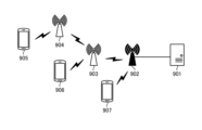
- FIG. 2 is a connection configuration diagram showing an example of a connection configuration of base stations that support access/backhaul integration.
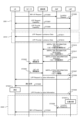
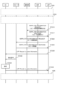
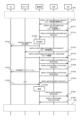
- FIG. 2 is a sequence diagram illustrating an example of a positioning procedure for a UE that connects to a base station via a repeater in accordance with the first embodiment;
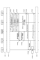
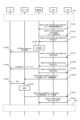
- FIG. 3 is a sequence diagram illustrating another example of a positioning procedure for a UE that connects to a base station via a repeater in Embodiment 1;
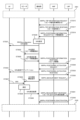
- FIG. 7 is a sequence diagram showing another example of a positioning procedure for a UE that connects to a base station via a repeater in Embodiment 2.
- FIG. 7 is a sequence diagram showing another example of a positioning procedure for a UE that connects to a base station via a repeater in Embodiment 2.
- FIG. FIG. 7 is a diagram illustrating an example of protocol stacks in a repeater, base station, AMF, and LMF in Embodiment 3;
- 7 is a diagram illustrating another example of protocol stacks in a repeater, base station, AMF, and LMF in Embodiment 3.
- FIG. FIG. 7 is a sequence diagram illustrating another example of a positioning procedure for a UE that connects to a base station via a repeater in Embodiment 3;
- FIG. 7 is a sequence diagram illustrating another example of a positioning procedure for a UE that connects to a base station via a repeater in Embodiment 3;
- FIG. 7 is a sequence diagram illustrating another example of a positioning procedure for a UE that connects to a base station via a repeater in Embodiment 3;
- FIG. 7 is a sequence diagram illustrating another example of a positioning procedure for a UE that connects to a base station via a repeater in Embodiment 3;
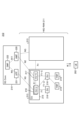
- FIG. 2 is a block diagram showing the overall configuration of an NR communication system 210 being discussed in 3GPP.
- the radio access network is called NG-RAN (Next Generation Radio Access Network) 211.
- a mobile terminal device hereinafter referred to as “mobile terminal (User Equipment: UE)”) 202, which is a communication terminal device, is capable of wireless communication with a base station device (hereinafter referred to as “NR base station (NG-RAN NodeB: gNB)”) 213. It transmits and receives signals via wireless communication.
- the NG-RAN 211 is configured by one or more NR base stations 213.
- the term “communication terminal device” includes not only mobile terminal devices such as movable mobile phone terminal devices, but also non-mobile devices such as sensors.
- a “communication terminal device” may be simply referred to as a “communication terminal.”
- the AS (Access Stratum) protocol is terminated between the UE 202 and the NG-RAN 211.
- AS protocols include, for example, RRC (Radio Resource Control), SDAP (Service Data Adaptation Protocol), PDCP (Packet Data Convergence Protocol), RLC (Radio Link Control), MAC (Medium Access Control), and PHY (Physical layer). used.
- RRC Radio Resource Control
- SDAP Service Data Adaptation Protocol
- PDCP Packet Data Convergence Protocol
- RLC Radio Link Control
- MAC Medium Access Control
- PHY Physical layer
- RRC Radio Resource Control
- SDAP Service Data Adaptation Protocol
- PDCP Packet Data Convergence Protocol
- RLC Radio Link Control
- MAC Medium Access Control
- PHY Physical layer
- the control protocol RRC Radio Resource Control
- RRC Radio Resource Control
- the states of the NR base station 213 and the UE 202 in RRC include RRC_IDLE, RRC_CONNECTED, and RRC_INACTIVE.
- RRC_IDLE PLMN (Public Land Mobile Network) selection, system information (SI) notification, paging, cell re-selection, mobility, etc. are performed.
- RRC_CONNECTED the mobile terminal has an RRC connection and can send and receive data to and from the network. Furthermore, in RRC_CONNECTED, handover (HO), measurement of neighbor cells, and the like are performed.
- RRC_INACTIVE maintains the connection between the 5G core unit 214 and the NR base station 213 while performing system information (SI) broadcasting, paging, cell re-selection, mobility, etc. It will be done.
- gNB213 is a 5G core unit (hereinafter referred to as "5GC") that includes an access and mobility management function (AMF), a session management function (SMF), or a user plane function (UPF). 214 (sometimes referred to as "part") by an NG interface. Control information and/or user data are communicated between the gNB 213 and the 5GC unit 214.
- the NG interface is a general term for the N2 interface between gNB 213 and AMF 220, the N3 interface between gNB 213 and UPF 221, the N11 interface between AMF 220 and SMF 222, and the N4 interface between UPF 221 and SMF 222.
- a plurality of 5GC units 214 may be connected to one gNB 213.
- the gNBs 213 are connected by an Xn interface, and control information and/or user data are communicated between the gNBs 213.
- the 5GC unit 214 is a higher-level device, specifically a higher-level node, and controls the connection between the NR base station 213 and the mobile terminal (UE) 202, and controls the connection between one or more NR base stations (gNB) 213 and/or LTE. It distributes paging signals to base stations (E-UTRAN NodeB: eNB). Further, the 5GC unit 214 performs mobility control in an idle state. The 5GC unit 214 manages a tracking area list when the mobile terminal 202 is in a standby state, an inactive state, and an active state. The 5GC unit 214 initiates a paging protocol by transmitting a paging message to a cell belonging to a tracking area in which the mobile terminal 202 is registered.
- the gNB 213 may constitute one or more cells. When one gNB 213 configures multiple cells, each cell is configured to be able to communicate with the UE 202.
- the gNB 213 may be divided into a central unit (hereinafter sometimes referred to as CU) 215 and a distributed unit (hereinafter sometimes referred to as DU) 216.
- CU central unit
- DU distributed unit
- One CU 215 is configured in the gNB 213.
- One or more DUs 216 are configured in the gNB 213.
- One DU 216 constitutes one or more cells.
- the CU 215 is connected to the DU 216 by an F1 interface, and control information and/or user data are communicated between the CU 215 and the DU 216.
- the F1 interface consists of an F1-C interface and an F1-U interface.
- the CU 215 is responsible for the functions of the RRC, SDAP, and PDCP protocols, and the DU 216 is responsible for the functions of the RLC, MAC, and PHY protocols.
- One or more TRPs (Transmission Reception Points) 219 may be connected to the DU 216 .
- the TRP 219 transmits and receives radio signals to and from the UE.
- the CU 215 may be divided into a C-plane CU (CU-C) 217 and a U-plane CU (CU-U) 218.
- One CU-C 217 is configured in the CU 215.
- One or more CU-Us 218 are configured in the CU 215.
- the CU-C 217 is connected to the CU-U 218 via an E1 interface, and control information is communicated between the CU-C 217 and CU-U 218.
- the CU-C 217 is connected to the DU 216 through an F1-C interface, and control information is communicated between the CU-C 217 and the DU 216.
- the CU-U 218 is connected to the DU 216 by an F1-U interface, and user data is communicated between the CU-U 218 and the DU 216.
- a 5G communication system may include a unified data management (UDM) function and a policy control function (PCF) described in Non-Patent Document 10 (3GPP TS23.501).
- the UDM and/or the PCF may be included in the 5GC section 214 in FIG.
- a location management function described in Non-Patent Document 24 (3GPP TS38.305) may be provided.
- the LMF may be connected to the base station via the AMF, as disclosed in Non-Patent Document 25 (3GPP TS23.273).
- a 5G communication system may include a non-3GPP interworking function (N3IWF) described in Non-Patent Document 10 (3GPP TS23.501).
- N3IWF non-3GPP interworking function
- the N3IWF may terminate an access network (AN) between the UE and the UE.
- AN access network
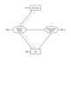
- FIG. 3 is a diagram showing the configuration of a DC (dual connectivity) connected to the NG core.
- DC dual connectivity
- solid lines indicate U-Plane connections
- broken lines indicate C-Plane connections.
- master base station 240-1 may be a gNB or an eNB.
- the secondary base station 240-2 may be a gNB or an eNB.
- NG-EN-DC a DC configuration in which master base station 240-1 is a gNB and secondary base station 240-2 is an eNB may be referred to as NG-EN-DC.
- FIG. 3 shows an example in which the U-Plane connection between the 5GC unit 214 and the secondary base station 240-2 is performed via the master base station 240-1, the 5GC unit 214 and the secondary base station 240-2 It may also be done directly between. Further, in FIG. 3, instead of the 5GC unit 214, an EPC (Evolved Packet Core), which is a core network connected to the LTE system and the LTE-A system, may be connected to the master base station 240-1. A U-Plane connection between the EPC and the secondary base station 240-2 may be made directly.
- EPC Evolved Packet Core
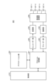
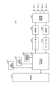
- FIG. 4 is a block diagram showing the configuration of the mobile terminal 202 shown in FIG. 2.
- the transmission processing of the mobile terminal 202 shown in FIG. 4 will be explained.
- control data from the control section 310 and user data from the application section 302 are sent to the protocol processing section 301 .
- Control data and user data may be buffered. Buffers for control data and user data may be provided in the control unit 310, the application unit 302, or the protocol processing unit 301.
- the protocol processing unit 301 performs operations such as processing protocols such as SDAP, PDCP, RLC, and MAC, determining a destination base station in a DC, etc., and adding headers in each protocol.
- the data that has been subjected to the protocol processing is passed to the encoder section 304, where it is subjected to encoding processing such as error correction.
- encoding processing such as error correction.
- the data encoded by the encoder section 304 is modulated by the modulation section 305.
- the modulation section 305 may perform MIMO precoding.
- the modulated data is converted into a baseband signal and then output to frequency conversion section 306, where it is converted into a wireless transmission frequency. Thereafter, transmission signals are transmitted to the base station 213 from the antennas 307-1 to 307-4.
- FIG. 4 illustrates an example in which the number of antennas is four, the number of antennas is not limited to four.
- the reception process of the mobile terminal 202 is executed as follows. Radio signals from base station 213 are received by antennas 307-1 to 307-4. The received signal is converted from a radio reception frequency to a baseband signal by frequency converter 306, and demodulated by demodulator 308. Demodulation section 308 may perform weight calculation and multiplication processing. The demodulated data is passed to a decoder section 309, where decoding processing such as error correction is performed. The decoded data is passed to the protocol processing unit 301, and protocol processing such as MAC, RLC, PDCP, SDAP, etc., such as header removal in each protocol, is performed. Among the data subjected to protocol processing, control data is passed to the control unit 310, and user data is passed to the application unit 302.
- protocol processing such as MAC, RLC, PDCP, SDAP, etc.
- a series of processing by the mobile terminal 202 is controlled by the control unit 310. Therefore, although not shown in FIG. 4, the control section 310 is also connected to each section 302, 304 to 309.
- Each section of the mobile terminal 202 is realized by a processing circuit including, for example, a processor and a memory.
- the control unit 310 is realized by a processor executing a program in which a series of processes of the mobile terminal 202 are described.
- a program that describes a series of processes for the mobile terminal 202 is stored in memory. Examples of memory are nonvolatile or volatile semiconductor memories such as RAM (Random Access Memory), ROM (Read Only Memory), and flash memory.
- Each part of the mobile terminal 202 for example, a control unit 310, a protocol processing unit 301, an encoder unit 304, and a decoder unit 309, is an FPGA (Field Programmable Gate Array), an ASIC (Application Specific Integrated Circuit), a DSP (Digital Signal Processor), etc. It may also be realized by a dedicated processing circuit.
- the number of antennas used by mobile terminal 202 for transmission and the number of antennas used for reception may be the same or different.
- FIG. 5 is a block diagram showing the configuration of base station 213 shown in FIG. 2. Transmission processing of the base station 213 shown in FIG. 5 will be explained.
- the EPC communication unit 401 transmits and receives data between the base station 213 and the EPC.
- the 5GC communication unit 412 transmits and receives data between the base station 213 and the 5GC (5GC unit 214, etc.).
- Other base station communication section 402 transmits and receives data to and from other base stations.
- the EPC communication unit 401, 5GC communication unit 412, and other base station communication unit 402 each exchange information with the protocol processing unit 403.
- Control data from the control unit 411 and user data and control data from the EPC communication unit 401, 5GC communication unit 412, and other base station communication unit 402 are sent to the protocol processing unit 403.
- Control data and user data may be buffered. Buffers for control data and user data may be provided in the control unit 411, in the EPC communication unit 401, in the 5GC communication unit 412, or in the other base station communication unit 402. may be provided.
- the protocol processing unit 403 performs operations such as processing protocols such as SDAP, PDCP, RLC, and MAC, for example, routing transmission data in a DC, etc., and adding headers in each protocol.
- the data that has been subjected to the protocol processing is passed to the encoder unit 405, where it is subjected to encoding processing such as error correction.
- encoding processing such as error correction.
- data sent from the 5GC communication unit 412 or the EPC communication unit 401 may be sent to another base station, for example, a secondary base station, via the other base station communication unit 402.
- the encoded data is subjected to modulation processing in modulation section 406.
- Precoding in MIMO may be performed in modulation section 406.
- the modulated data is converted into a baseband signal, it is output to frequency conversion section 407 and converted into a wireless transmission frequency.
- transmission signals are transmitted to one or more mobile terminals 202 from antennas 408-1 to 408-4.
- FIG. 5 illustrates an example in which the number of antennas is four, the number of antennas is not limited to four.
- the reception processing of the base station 213 is executed as follows. Radio signals from one or more mobile terminals 202 are received by antennas 408-1 through 408-4. The received signal is converted from a radio reception frequency to a baseband signal by a frequency converter 407, and demodulated by a demodulator 409. The demodulated data is passed to a decoder section 410, where decoding processing such as error correction is performed. The decoded data is passed to the protocol processing unit 403, where protocol processing such as MAC, RLC, PDCP, SDAP, etc., such as header removal in each protocol, is performed.
- protocol processing such as MAC, RLC, PDCP, SDAP, etc.
- control data is passed to the control unit 411, 5GC communication unit 412, EPC communication unit 401, or other base station communication unit 402
- user data is passed to the 5GC communication unit 412, EPC communication unit 401, or other base station communication unit 402. It is passed to the other base station communication section 402.
- Data sent from the other base station communication section 402 may be sent to the 5GC communication section 412 or the EPC communication section 401.
- the data may be, for example, upstream data sent to the 5GC communication unit 412 or the EPC communication unit 401 via another base station in the DC.
- control section 411 is also connected to each section 401, 402, 405 to 410, 412.
- Each unit of the base station 213, for example, the control unit 411, protocol processing unit 403, 5GC communication unit 412, EPC communication unit 401, other base station communication unit 402, encoder unit 405, and decoder unit 410, is the same as the mobile terminal 202 described above. It is realized by a processing circuit including a processor and memory, or a dedicated processing circuit such as FPGA, ASIC, or DSP. In FIG. 5, the number of antennas used by base station 213 for transmission and the number of antennas used for reception may be the same or different.
- a device with a The DU communication unit connects to the protocol processing unit 403.
- a protocol processing unit 403 in the CU 215 performs protocol processing such as PDCP and SDAP.
- a configuration in which a CU communication unit is provided except for the EPC communication unit 401, other base station communication unit 402, and 5GC communication unit 412 shown in FIG. 5 may be used.
- the CU communication unit connects to the protocol processing unit 403.
- a protocol processing unit 403 in the DU 216 performs protocol processing such as PHY, MAC, and RLC.
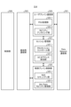
- FIG. 6 is a block diagram showing the configuration of the 5GC section.
- FIG. 6 shows the configuration of the 5GC unit 214 shown in FIG. 2 described above.
- FIG. 6 shows a case where the 5GC section 214 shown in FIG. 2 includes an AMF configuration, an SMF configuration, and a UPF configuration.
- the AMF has the function of the control plane control unit 525
- the SMF has the function of the session management unit 527
- the UPF has the functions of the user plane communication unit 523 and the Data Network communication unit 521. good.
- the Data Network communication unit 521 transmits and receives data between the 5GC unit 214 and the Data Network.
- the base station communication unit 522 transmits and receives data between the 5GC unit 214 and the base station 213 via the NG interface.
- User data sent from the Data Network is passed from the Data Network communication unit 521 to the base station communication unit 522 via the user plane communication unit 523, and is transmitted to one or more base stations 213.
- User data sent from the base station 213 is passed from the base station communication unit 522 to the Data Network communication unit 521 via the user plane communication unit 523, and is transmitted to the Data Network.
- the control data sent from the base station 213 is passed from the base station communication section 522 to the control plane control section 525.
- the control plane controller 525 may pass control data to the session manager 527.
- Control data may be sent from the Data Network.
- the control data sent from the Data Network may be sent from the Data Network communication section 521 to the session management section 527 via the user plane communication section 523.
- the session management unit 527 may send control data to the control plane control unit 525.
- the user plane control unit 523 includes a PDU processing unit 523-1, a mobility anchoring unit 523-2, and the like, and performs overall processing for the user plane (hereinafter sometimes referred to as U-Plane).
- the PDU processing unit 523-1 processes data packets, for example, transmits and receives packets to and from the Data Network communication unit 521 and transmits and receives packets to and from the base station communication unit 522.
- the mobility anchoring unit 523-2 is responsible for anchoring data paths when the UE is mobile.
- the session management unit 527 manages the PDU session established between the UE and the UPF.
- the session management unit 527 includes a PDU session control unit 527-1, a UE IP address assignment unit 527-2, and the like.
- the PDU session control unit 527-1 manages the PDU session between the mobile terminal 202 and the 5GC unit 214.
- the UE IP address assignment unit 527-2 assigns an IP address to the mobile terminal 202, etc.
- the control plane control unit 525 includes a NAS security unit 525-1, an idle state mobility management unit 525-2, and the like, and performs overall processing for the control plane (hereinafter sometimes referred to as C-Plane).
- the NAS security unit 525-1 performs security for NAS (Non-Access Stratum) messages.
- the idle state mobility management unit 525-2 manages mobility in the standby state (Idle State: RRC_IDLE state, or simply referred to as idle), generates and controls paging signals during the standby state, and performs the following functions: Adding, deleting, updating, searching, tracking area list management, etc. of one or more mobile terminals 202 are performed.
- each part of the 5GC unit 214 is realized, for example, by a processing circuit including a processor and a memory, or a dedicated processing circuit such as an FPGA, an ASIC, or a DSP. Ru.
- FIG. 7 is a flowchart schematically showing steps from cell search to standby operation performed by a communication terminal (UE) in the NR communication system.
- the communication terminal starts cell search, in step ST601, the communication terminal determines the slot timing and frame using the first synchronization signal (P-SS) and the second synchronization signal (S-SS) transmitted from surrounding base stations. Synchronize timing.
- P-SS first synchronization signal
- S-SS second synchronization signal
- P-SS and S-SS are collectively referred to as a synchronization signal (SS).
- a synchronization code that corresponds one-to-one to a PCI (Physical Cell Identifier) assigned to each cell is assigned to the synchronization signal (SS).
- PCI Physical Cell Identifier
- 1008 types of PCI are being considered. The communication terminal synchronizes using these 1008 PCIs and detects (identifies) the PCI of the synchronized cell.
- the communication terminal receives the PBCH from the next synchronized cell in step ST602.
- a MIB Master Information Block
- the MIB information includes, for example, SFN (System Frame Number), SIB (System Information Block) 1 scheduling information, subcarrier intervals such as SIB 1, and DM-RS position information.
- the communication terminal acquires the SS block identifier from the PBCH.
- a part of the bit string of the SS block identifier is included in the MIB.
- the remaining bit strings are included in the identifier used to generate the sequence of DM-RS accompanying the PBCH.
- the communication terminal obtains the SS block identifier using the MIB included in the PBCH and the DM-RS sequence accompanying the PBCH.
- step ST603 the communication terminal measures the received power of the SS block.
- the communication terminal selects the cell with the best reception quality, for example, the cell with the highest reception power, ie, the best cell, from among the one or more cells detected up to step ST603. Further, the communication terminal selects a beam with the best reception quality, for example, a beam with the highest reception power of the SS block, that is, the best beam. For example, the received power of the SS block for each SS block identifier is used to select the best beam.
- SIB1 includes information regarding access to the cell, cell configuration information, and scheduling information of other SIBs (SIBk: an integer of k ⁇ 2). SIB1 also includes a tracking area code (TAC).
- TAC tracking area code
- the communication terminal compares the TAC of SIB1 received in step ST605 with the TAC part of the tracking area identifier (Tracking Area Identity: TAI) in the tracking area list already held by the communication terminal.
- the tracking area list is also referred to as a TAI list.
- TAI is identification information for identifying a tracking area, and is composed of MCC (Mobile Country Code), MNC (Mobile Network Code), and TAC (Tracking Area Code).
- MCC is the country code.
- MNC is a network code.
- TAC is the tracking area code number.
- step ST606 if the TAC received in step ST605 is the same as the TAC included in the tracking area list, the communication terminal enters a standby operation in the cell. In comparison, if the TAC received in step ST605 is not included in the tracking area list, the communication terminal transmits TAU (Tracking Area Update) to the core network (EPC) including the MME etc. through the cell. Request a tracking area change in order to do so.
- TAU Tracking Area Update
- core network side devices Devices that make up the core network (hereinafter sometimes referred to as “core network side devices”) perform tracking based on the identification number (UE-ID, etc.) of the communication terminal sent from the communication terminal along with the TAU request signal. Update the area list.
- the core network side device transmits the updated tracking area list to the communication terminal.
- the communication terminal rewrites (updates) the TAC list held by the communication terminal based on the received tracking area list. Thereafter, the communication terminal enters a standby operation in the cell.
- random access 4-step random access and 2-step random access are used.
- 4-step random access and 2-step random access contention-based random access, that is, random access where timing collision with other mobile terminals may occur, and collision-free (contention-based) random access, contention-free) random access exists.
- the mobile terminal transmits a random access preamble to the base station.
- the random access preamble may be selected by the mobile terminal from within a predetermined range, or may be individually assigned to the mobile terminal and notified from the base station.
- the base station transmits a random access response to the mobile terminal.
- the random access response includes uplink scheduling information used in the third step, a terminal identifier used in uplink transmission in the third step, and the like.
- the mobile terminal performs uplink transmission to the base station.
- the mobile terminal uses the information acquired in the second step for uplink transmission.
- the base station notifies the mobile terminal whether or not there is a conflict resolution.
- the mobile terminal that is notified that there is no collision ends the random access process.
- the mobile terminal that is notified that there is a collision restarts the process from the first step.
- the collision-free 4-step random access method differs from the collision-based 4-step random access method in the following points. That is, prior to the first step, the base station allocates a random access preamble and uplink scheduling to the mobile terminal in advance. Further, the notification of whether or not the conflict is resolved in the fourth step is not required.
- the mobile terminal transmits a random access preamble and performs uplink transmission to the base station.
- the base station notifies the mobile terminal of the presence or absence of a collision.
- the mobile terminal that is notified that there is no collision ends the random access process.
- the mobile terminal that is notified that there is a collision restarts the process from the first step.
- the collision-free two-step random access method differs from the collision-based two-step random access method in the following points. That is, prior to the first step, the base station allocates a random access preamble and uplink scheduling to the mobile terminal in advance. Also, in the second step, the base station transmits a random access response to the mobile terminal.
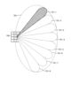
- FIG. 8 shows an example of a cell configuration in NR.
- a narrow beam is formed and transmitted by changing direction.
- base station 750 performs transmission and reception with a mobile terminal using beam 751-1 at a certain time. At other times, base station 750 transmits to and receives from mobile terminals using beam 751-2. Similarly, the base station 750 uses one or more of the beams 751-3 to 751-8 to perform transmission and reception with the mobile terminal. In this way, the base station 750 configures a wide area cell 752.
- FIG. 8 shows an example in which the number of beams used by the base station 750 is eight, the number of beams may be different from eight. Furthermore, in the example shown in FIG. 8, the number of beams that the base station 750 uses simultaneously is one, but it may be plural.
- the concept of QCL is used for beam identification (see Non-Patent Document 14 (3GPP TS38.214)). That is, the beam is identified by information indicating which reference signal (eg, SS block, CSI-RS) beam can be regarded as the same beam.
- the information may include the type of information regarding viewpoints that can be regarded as the same beam, for example, information regarding Doppler shift, Doppler shift spread, average delay, average delay spread, and spatial Rx parameters (Non-patent Document 14 ( 3GPP TS38.214)).
- SL Side Link
- D2D Device to Device
- V2V Vehicle to Vehicle
- PC5-S signaling is implemented to establish a link for implementing SL, ie, PC5 communication.
- the link is implemented at the V2X layer and is also referred to as a layer 2 link.
- RRC signaling in SL communication is also referred to as PC5 RRC signaling.
- PC5 RRC signaling it has been proposed to notify UE capabilities between UEs that perform PC5 communication, and to notify AS layer settings for performing V2X communication using PC5 communication.
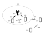
- FIG. 9 shows an example of a connection configuration of mobile terminals in SL communication.
- UE 805 and UE 806 exist within coverage 803 of base station 801.
- UL/DL communication 807 is performed between base station 801 and UE 805.
- UL/DL communication 808 is performed between base station 801 and UE 806.
- SL communication 810 is performed between UE 805 and UE 806.
- UE 811 and UE 812 exist outside the coverage 803.
- SL communication 814 is performed between UE 805 and UE 811.
- SL communication 816 is performed between UE 811 and UE 812.
- a UE 805 shown in FIG. 9 relays communication between a UE 811 and a base station 801.
- a configuration similar to that in FIG. 4 may be used for a UE that performs relaying.
- Relay processing in the UE will be explained using FIG. 4.
- Relay processing by the UE 805 in communication from the UE 811 to the base station 801 will be described.
- Radio signals from UE 811 are received by antennas 307-1 to 307-4.
- the received signal is converted from a radio reception frequency to a baseband signal by frequency converter 306, and demodulated by demodulator 308.
- Demodulation section 308 may perform weight calculation and multiplication processing.
- the demodulated data is passed to a decoder section 309, where decoding processing such as error correction is performed.
- the decoded data is passed to the protocol processing unit 301, and protocol processing such as MAC and RLC used for communication with the UE 811, such as header removal in each protocol, is performed. It also performs protocol processing such as RLC and MAC used for communication with the base station 801, such as adding headers in each protocol.
- the protocol processing unit 301 of the UE 811 may perform PDCP and SDAP protocol processing.
- the data that has been subjected to the protocol processing is passed to the encoder section 304, where it is subjected to encoding processing such as error correction. There may be data that is directly output from the protocol processing section 301 to the modulation section 305 without being subjected to encoding processing.
- the data encoded by the encoder section 304 is modulated by the modulation section 305.
- the modulation section 305 may perform MIMO precoding.
- the modulated data is converted into a baseband signal and then output to frequency conversion section 306, where it is converted into a wireless transmission frequency. Thereafter, transmission signals are transmitted to the base station 801 from the antennas 307-1 to 307-4.
- a 5G base station can support integrated access and backhaul (IAB) (see Non-Patent Documents 2 and 20).
- a base station that supports IAB (hereinafter sometimes referred to as an IAB base station) is an IAB donor CU, which is a CU of a base station that operates as an IAB donor that provides IAB functions, and a DU of a base station that operates as an IAB donor. It is composed of an IAB donor DU and an IAB node that is connected to the IAB donor DU and to the UE using a wireless interface. An F1 interface is provided between the IAB node and the IAB donor CU (see Non-Patent Document 2).
- IAB donor CU901 is connected to IAB donor DU902.
- IAB node 903 is connected to IAB donor DU 902 using a wireless interface.
- IAB node 903 is connected to IAB node 904 using a wireless interface. That is, IAB nodes may be connected in multiple stages.
- the UE 905 is connected to the IAB node 904 using a wireless interface.
- the UE 906 may be connected to the IAB node 903 using a wireless interface, and the UE 907 may be connected to the IAB donor DU 902 using a wireless interface.
- a plurality of IAB donor DUs 902 may be connected to an IAB donor CU 901, a plurality of IAB nodes 903 may be connected to an IAB donor DU 902, and a plurality of IAB nodes 904 may be connected to an IAB node 903. There may be cases where
- a BAP (Backhaul Adaptation Protocol) layer is provided in the connection between the IAB donor DU and the IAB node and the connection between the IAB nodes (see Non-Patent Document 29).
- the BAP layer performs operations such as routing received data to an IAB donor DU and/or IAB node and mapping it to an RLC channel (see Non-Patent Document 29).
- the protocol processing unit of the IAB donor DU performs BAP layer processing, such as adding a BAP header to downlink data, routing to an IAB node, and removing the BAP header from uplink data.
- the configuration shown in FIG. 5 excluding the EPC communication section 401, other base station communication section 402, and 5GC communication section 412 may be used.
- Transmission and reception processing at the IAB node will be explained using FIGS. 5 and 10. Transmission and reception processing of the IAB node 903 in communication between the IAB donor CU 901 and the UE 905 will be described.
- a radio signal from the IAB node 904 is received by the antenna 408 (some or all of the antennas 408-1 to 408-4).
- the received signal is converted from a radio reception frequency to a baseband signal by a frequency converter 407, and demodulated by a demodulator 409.
- the demodulated data is passed to a decoder section 410, where decoding processing such as error correction is performed.
- the decoded data is passed to the protocol processing unit 403, where it performs protocol processing such as MAC and RLC used for communication with the IAB node 904, such as header removal in each protocol. Further, routing to the IAB donor DU 902 using the BAP header is performed, and protocol processing such as RLC and MAC used for communication with the IAB donor DU 902 is performed, for example, operations such as adding headers in each protocol are performed.
- the data that has been subjected to the protocol processing is passed to the encoder unit 405, where it is subjected to encoding processing such as error correction. There may also be data that is directly output from protocol processing section 403 to modulation section 406 without being subjected to encoding processing.
- the encoded data is subjected to modulation processing in modulation section 406.
- Precoding in MIMO may be performed in modulation section 406.
- the modulated data is converted into a baseband signal, it is output to frequency conversion section 407 and converted into a wireless transmission frequency.
- transmission signals are transmitted to the IAB donor DU 902 from the antennas 408-1 to 408-4. Similar processing is performed in downlink communication from the IAB donor CU 901 to the UE 905.
- the IAB node 904 also performs the same transmission and reception processing as the IAB node 903.
- the protocol processing unit 403 of the IAB node 903 performs BAP layer processing such as adding a BAP header in uplink communication and routing to the IAB node 904, and removing the BAP header in downlink communication.
- a repeater may be used for communication between a base station and a UE (hereinafter sometimes referred to as an access link (AL) (see Non-Patent Document 31)).
- a repeater may have multiple beams.
- the repeater may receive a signal from a transmission source, amplify it, and transmit the amplified signal to a transmission destination (this operation may be referred to as AL transmission/reception).
- the repeater may use beams for AL transmission and reception.
- the base station may control the repeater.
- the base station may transmit a control signal to the repeater (a link used for transmitting a control signal between the base station and the repeater is sometimes referred to as a fronthaul link (FL) (Non-patent Document 31). reference)).
- FL fronthaul link
- L1/L2 signaling may be used for the control signal.
- the base station may control the beams used by the repeaters.
- the control by the base station may be, for example, beam switching.
- the base station may, for example, switch beams in response to movement of the UE.
- Positioning of a UE connected to a base station via a repeater may be performed.
- the UE may receive positioning signals transmitted by a base station.
- the positioning signal may be, for example, a PRS.
- the UE may notify the LMF of the reception result of the positioning signal.
- the reception result of the positioning signal may include, for example, information regarding the difference between the reception time of the positioning signal from the base station and the reception time of the positioning signal from another base station.
- the LMF may use the information to calculate the UE's location.
- the UE since the UE is connected to the base station via a repeater, the difference between the time when the UE receives the positioning signal and the time when the positioning signal is transmitted from the base station is directly correlated to the distance between the base station and the UE. do not have. As a result, a problem arises in that the location calculation result of the UE becomes inaccurate.
- Embodiment 1 discloses a method for solving such problems.
- the base station notifies the LMF of information regarding the repeater.
- the information may include, for example, information regarding delay time in the repeater.
- the information regarding the delay time may be, for example, the time from when the repeater receives the signal until it transmits the signal.
- the base station may specify the delay time at the repeater in advance.
- the base station may notify the repeater of the specified delay time.
- the repeater After receiving the positioning signal from the base station, the repeater may transmit the positioning signal to the UE when the specified time has elapsed. This makes it possible to reduce, for example, the processing amount of the repeater related to delay time derivation in the repeater.
- the information regarding the repeater that is notified from the base station to the LMF may include information regarding the propagation delay from the base station to the repeater, information regarding the position of the repeater, or both of the above information. may be included.
- the information regarding the position of the repeater may be information about the position of the repeater itself, information about the relative position between the base station and the repeater, or information about the distance between the base station and the repeater. or a combination of the above-mentioned plurality.
- the LMF may use the information to derive the propagation delay between the base station and the LMF. This makes it possible to improve the accuracy of UE position calculation, for example, regardless of the positional relationship between the base station, repeater, and UE.
- NRPPa signaling may be used for this notification from the base station to the LMF.
- OTDOA Observed Time Difference Of Arrival
- OTDOA Observed Time Difference Of Arrival
- positioning information response POSITIONING INFORMATION RESPONSE
- positioning information update POSITIONING INFORMATION UPDATE
- TRP INFORMATION RESPONSE positioning activation response
- PRS CONFIGURATION RESPONSE PRS configuration response
- measurement preconfiguration confirmation MEASUREMENT PRECONFIGURATION CONFIRM
- assistance information feedback ASSISTANCE INFORMATION FEEDBACK
- New NRPPa signaling may be provided.
- New NRPPa signaling may be used
- the LMF may request information regarding repeaters from the base station.
- NRPPa signaling may be used for the request.
- OTDOA information request OTDOA INFORMATION REQUEST
- positioning information request POSITIONING INFORMATION REQUEST
- TRP information request TRP INFORMATION REQUEST
- signaling of a positioning activation request POSITIONING ACTIVATION REQUEST
- PRS CONFIGURATION REQUEST PRS CONFIGURATION REQUEST
- MASUREMENT measurement preconfiguration request
- PRECONFIGURATION REQUIRED signaling may be used, or assistance information control (ASSISTANCE INFORMATION CONTROL) signaling may be used. This makes it possible, for example, to avoid complications in the communication system.
- New NRPPa signaling may be provided. New NRPPa signaling may be used for the request from the LMF to the base station. The request may trigger the notification of the information regarding the repeater from the base station to the LMF.
- the repeater may notify the base station of the information on its own repeater.
- Msg3 in 4-step random access processing may be used
- MsgA in 2-step random access processing may be used
- other signaling such as RRC setup completion (RRCSetupComplete) ( Non-Patent Document 19 (3GPP TS38.331)) may be used.
- the information may be included in a capability (eg, UE capability) and notified.
- the information may be notified from the repeater to the base station in response to a request from the base station.
- the base station may request information regarding the repeater from the repeater in advance.
- Msg2 in the 4-step random access process may be used for the request from the base station to the repeater, or other signaling, such as RRC startup request signaling (Non-patent Document 19 (3GPP TS38.331 ) may be used.
- the request may be included in a capability (eg, UE capability) request and notified.
- the request from the base station to the repeater may be made in response to the above-mentioned request from the LMF to the base station.
- the base station may notify the repeater of settings related to positioning signals.
- the settings may include information regarding time/frequency resources of the positioning signal, information regarding the code sequence of the positioning signal, and information regarding the amplification factor in the repeater. , information regarding the transmission power at the repeater, information regarding the transmission timing of the signal at the repeater, and information regarding beamforming at the repeater may be included.
- the repeater can determine the positioning signal transmitted from the base station, and as a result, the repeater can appropriately control the positioning signal, e.g., receive it from the base station and transmit it to the UE. It becomes possible.
- the repeater can acquire the above-mentioned information regarding the processing delay in the repeater itself, for example, information about the time from when the repeater receives a signal until it transmits the signal.
- the settings may include information regarding the QCL of the positioning signal.
- the information may include information indicating which reference signal (eg, SS block, CSI-RS) beam the positioning signal can be considered to be the same beam. From this information, the repeater may acquire information regarding the beam used for transmitting the positioning signal. This makes it possible to reduce the size of information related to positioning signal settings, for example.
- reference signal eg, SS block, CSI-RS
- the LMF may inquire of the base station whether or not a repeater is used.
- the inquiry may include information identifying the repeater, for example, the repeater's identifier, or may include information regarding the UE that communicates with the base station via the repeater.
- NRPPa signaling for example, NRPPa TRP INFORMATION REQUEST signaling may be used for the inquiry from the LMF to the base station.
- New NRPPa signaling may be provided. The new NRPPa signaling may be used for the inquiry from the LMF to the base station.
- the base station may notify the LMF of information regarding whether or not a repeater is used.
- the information may include information identifying the repeater, for example, a repeater identifier, or may include information regarding a UE that communicates with the base station via the repeater.
- the information may be notified in response to the above-mentioned inquiry from the LMF to the base station.
- NRPPa signaling for example, NRPPa TRP INFORMATION RESPONSE signaling may be used for the notification from the base station to the LMF.
- New NRPPa signaling may be provided. The new NRPPa signaling may be used for the notification from the base station to the LMF.
- the UE may receive the positioning signal transmitted via the repeater.
- the UE may notify the LMF of the reception result of the positioning signal.
- LPP signaling (see Non-Patent Document 34 (3GPP TS37.355)) may be used for the notification.
- the LMF may use the information to calculate the UE's location.
- the LMF may use the above-mentioned information regarding the repeater notified from the base station. This allows, for example, the LMF to accurately calculate the location of the UE.
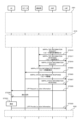
- FIG. 11 is a sequence diagram illustrating an example of a positioning procedure for a UE that connects to a base station via a repeater.
- OTDOA positioning is performed.
- a base station transmits a positioning signal.
- FIG. 11 shows an example in which positioning is performed in response to a location information request (Mobile-Originated Location Request: MO-LR) from a UE.
- FIG. 11 shows an example in which UE-assisted positioning (positioning in which an LMF or the like calculates a position using assistance information from the UE (eg, positioning signal reception result)) is performed.
- UE-assisted positioning positioning in which an LMF or the like calculates a position using assistance information from the UE (eg, positioning signal reception result)
- signal transmission and reception between the UE, base station, AMF, and LMF is performed via repeaters.
- the side control information transmitted from the base station to the repeater is omitted in FIG. 11, the side control information is transmitted prior to signal transmission and reception between the UE and the base station, AMF, and LMF.
- the base station instructs the repeater to set a beam. The same applies to the figures after FIG. 11.
- procedure 2301 shown in FIG. 11 a positioning request from the UE and a positioning capability request and notification between the LMF and the UE are performed.
- Step ST2303 indicates the request from the UE to the AMF
- step ST2305 indicates the request from the AMF to the LMF.
- a positioning capability request is made from the LMF to the UE.
- the request is made using LPP signaling, for example, LPP Request Capability.
- the UE notifies the LMF of the positioning capability.
- the notification is performed using LPP signaling, for example, LPP Provide Capability.
- step ST2311 the LMF requests support data from the UE.
- the request is made using LPP signaling, eg, LPP assistance data request signaling.
- step ST2313 the UE notifies the LMF of the support data.
- the notification is performed using LPP signaling, for example LPP support data provision signaling.
- the LMF requests the base station for information regarding whether or not a repeater is used.
- the request may use NRPPa signaling, for example, NRPPa TRP information request signaling.
- the request may include a request for information regarding the TRP of the base station.
- the request for information regarding whether or not a repeater is used may include information that identifies the repeater, for example, a request for a repeater identifier, or may include a request for information regarding a UE that communicates with a base station via the repeater. Good too.
- the base station notifies the LMF of information regarding whether or not a repeater is used.
- NRPPa signaling for example, NRPPa TRP information response signaling may be used for the notification.
- the notification may include information regarding the TRP. In the example shown in FIG. 11, information indicating that a repeater is used is notified.
- the LMF requests information necessary for OTDOA from the base station.
- the request may use NRPPa signaling, for example, NRPPa OTDOA information request signaling.
- the request may include a request for information regarding the repeater.
- the information may include information regarding an instruction to start transmitting a positioning signal.
- the base station may transmit a positioning signal, for example, PRS, using step ST2319 as an opportunity.
- step ST2322 shown in FIG. 11 the base station requests information regarding the repeater from the repeater.
- the request may be made using, for example, L1/L2 signaling, MAC signaling, RRC signaling, or a combination of the above. It may also be carried out using
- step ST2325 the repeater notifies the base station of information regarding its own repeater. The notification may be performed using, for example, L1/L2 signaling, MAC signaling, RRC signaling, or a combination of the above. It may also be carried out using
- the base station notifies the LMF of information necessary for OTDOA.
- the notification may use NRPPa signaling, for example, NRPPa OTDOA information response signaling.
- the notification may include information regarding the repeater.
- the information about the repeater may include, for example, information about the propagation delay from the base station to the repeater, information about the location of the repeater, information about processing delays at the repeater, etc. Good too.
- the LMF instructs the UE to receive the positioning signal.
- the instruction may be performed using LPP signaling, for example, LPP Request Location Information signaling.
- the instruction may include information regarding the received positioning signal.
- the UE starts receiving the positioning signal.
- a positioning signal is transmitted from the base station to the UE.
- the transmission takes place via a repeater.
- the repeater receives a positioning signal from the base station and transmits the signal to the UE.
- the UE measures the positioning signal transmitted from the base station via the repeater.
- the UE reports the measurement results of the positioning signal to the LMF.
- the report may be performed using LPP signaling, for example, LPP Provide Location Information signaling.
- the report may include information regarding the difference between the reception time of the received positioning signal received from the base station via the repeater and the reception time of the positioning signal received from other base stations, Information about the station may also be included.
- the positioning signal received by the UE from another base station may be a positioning signal directly received from another base station, or may be a positioning signal received via a repeater connected to the base station. The UE may not be aware of whether the received positioning signal is received directly from the base station or via a repeater.
- procedure 2335 shown in FIG. 11 the UE position calculation and notification of the position calculation result are performed.
- the LMF calculates the location of the UE.
- the LMF may perform this calculation using the positioning signal measurement results obtained in step ST2333, may perform the calculation using the information regarding the repeater obtained in step ST2327, or may perform the calculation using both of the above. Good too.
- Step ST2339 shows the notification from the LMF to the AMF
- step ST2341 shows the notification from the AMF to the UE.
- MT-LR Mobile-Terminated Location Request
- NI-LR network-induced location request
- the repeater may generate and transmit the positioning signal.
- the positioning signal transmitted by the repeater may be, for example, PRS.
- the base station may notify the repeater of the positioning signal settings.
- the notification may include information regarding the time/frequency resources of the positioning signal, information regarding the beam used for transmitting the positioning signal, and information regarding the code sequence of the positioning signal. Good too.
- the notification may include a request for information regarding the repeater.
- the notification from the base station to the repeater may use L1/L2 signaling, MAC signaling, RRC signaling, or a combination of the above. It's okay to be hit.
- the repeater may use the information obtained from the notification to configure the positioning signal.
- the repeater may start transmitting the positioning signal in response to the notification.
- the repeater may notify the base station that the setting of the positioning signal is completed. In this notification, information regarding the own repeater may be notified.
- the information regarding repeaters may be the same as described above.
- the notification from the repeater to the base station may use L1/L2 signaling, MAC signaling, RRC signaling, or a combination of the above. You can.
- FIG. 12 is a sequence diagram showing another example of a positioning procedure for a UE that connects to a base station via a repeater.
- OTDOA positioning is performed.
- a repeater transmits a positioning signal.
- processes similar to those in FIG. 11 are given the same numbers, and common explanations will be omitted.
- the base station notifies the repeater of the setting of the positioning signal.
- the notification may include information regarding resources for positioning signals, or may include information regarding beams used for transmitting positioning signals.
- the notification may include a request for information regarding the repeater.
- Step ST2422 may use L1/L2 signaling, MAC signaling, RRC signaling, or a combination of the aforementioned plurality.
- the repeater sets the positioning signal using the information received in step ST2422.
- the repeater may notify the base station that the positioning signal setting has been completed.
- the notification may include information regarding the own repeater.
- the information regarding repeaters may be the same as described above.
- Step ST2425 may use L1/L2 signaling, MAC signaling, RRC signaling, or a combination of the aforementioned plurality.
- Steps ST2327 and ST2329 shown in FIG. 12 are the same as in FIG. 11.
- step ST2430 shown in FIG. 12 the repeater transmits a positioning signal to the UE.
- the transmission may be performed using the settings notified in step ST2422.
- Steps ST2331, ST2333, and procedure 2335 shown in FIG. 12 are the same as in FIG. 11.
- the base station may notify information regarding the repeater to devices other than the LMF.
- the information regarding repeaters may be used in other core NW devices.
- the base station may notify the AMF of the information.
- the AMF may use the information, for example, to register repeaters.
- the AMF may use, for example, position information of the repeater to determine whether the repeater can be registered in the NW. This makes it possible, for example, to prevent the repeater from being used in locations where it is not permitted to transmit.
- the repeater may have a positioning function.
- a repeater may have the same functionality as a UE regarding positioning. Positioning of the repeater itself may also be performed.
- repeater positioning a method similar to UE positioning may be used, the same signaling as UE positioning may be used, or the same signaling as UE positioning may be used.
- a repeater may derive its own position. This derivation in the repeater may be performed, for example, in a method similar to UE-based positioning (a positioning method in which a UE derives its own position). This makes it possible to reduce the amount of processing related to position calculation in the LMF, for example.
- Positioning of the repeater and the UE may be performed simultaneously.
- the repeater and/or the UE may receive positioning signals transmitted by the base station.
- the positioning signals received by the repeater and the UE may be the same or different.
- the UE may notify the LMF of the measurement results of the positioning signal.
- a repeater may notify a base station of information regarding its own repeater, for example, a processing delay at its own repeater.
- the base station may notify the LMF of this information.
- the LMF may use the above information to calculate the repeater and UE locations. By this, for example, positioning of the repeater and the UE can be performed quickly.
- the method disclosed in Embodiment 1 may be switched and used. For example, transmission of a positioning signal from a base station and generation and transmission of a positioning signal from a repeater may be switched.
- the base station may notify the repeater of information regarding the switching.
- the information may be, for example, information indicating whether the positioning signal is received from the base station and transmitted to the UE, or whether it is generated by the repeater itself.
- the repeater may receive a positioning signal from the base station and transmit it to the UE, or may generate a positioning signal at its own repeater and transmit it to the UE. This makes it possible, for example, to improve flexibility in positioning.
- the method disclosed in Embodiment 1 may be used in UE-based positioning.
- the LMF may notify the UE of information regarding the repeater.
- the notification may use LPP signaling, for example, LPP support data supply signaling, or may use other LPP signaling.
- the base station may notify the UE of the information regarding the repeater.
- RRC signaling, MAC signaling, or L1/L2 signaling may be used for notification from the base station to the UE.
- the UE may derive its own location using the information notified from the LMF and/or the base station. As a result, for example, even in UE-based positioning, it is possible to improve the positioning accuracy of a UE connected to a base station via a repeater.
- the first embodiment it is possible to ensure positioning accuracy even in positioning a UE connected to a base station via a repeater.
- Embodiment 2 In positioning using uplink signals, a method similar to that of Embodiment 1 may be applied. Positioning using uplink signals may be, for example, UL-TDOA (see Non-Patent Document 24 (3GPP TS38.305)).
- a UE connected to a base station via a repeater may transmit an SRS, and the base station may receive the SRS.
- the repeater may receive the SRS transmitted by the UE and transmit it to the base station.
- the repeater may amplify the SRS transmitted by the UE and transmit it to the base station.
- a repeater may perform the amplification operation and/or the transmission operation in conjunction with other channels/signals.
- the base station may notify the LMF of information regarding the repeater.
- the information may include, for example, the same information as the information disclosed in Embodiment 1.
- the information regarding the repeater that is notified from the base station to the LMF may include information regarding the propagation delay from the base station to the repeater, information regarding the position of the repeater, or both of the above information. may be included.
- the repeater may notify the base station of the information regarding its own repeater.
- Msg3 in 4-step random access processing may be used
- MsgA in 2-step random access processing may be used
- other signaling such as RRC setup completion (RRCSetupComplete) ( Non-Patent Document 19 (3GPP TS38.331)) may be used.
- the information may be included in a capability (eg, UE capability) and notified.
- the information may be notified from the repeater to the base station in response to a request from the base station.
- the base station may request information regarding the repeater from the repeater in advance.
- Msg2 in the 4-step random access process may be used for the request from the base station to the repeater, or other signaling, such as RRC startup request signaling (Non-patent Document 19 (3GPP TS38.331 ) may be used.
- the request may be included in a capability (eg, UE capability) request and notified.
- FIG. 13 is a sequence diagram showing another example of the positioning procedure of a UE that connects to a base station via a repeater.
- UL-TDOA positioning is performed.
- the UE transmits an SRS and the base station receives it.
- processes similar to those in FIG. 11 are given the same numbers, and common explanations will be omitted.
- the LMF requests information necessary for positioning from the base station.
- the request may use NRPPa signaling, for example, NRPPa positioning information request signaling.
- the request may include a request for information regarding the repeater.
- the information may include instructions for SRS configuration.
- the base station performs SRS settings.
- the base station instructs the UE to transmit SRS.
- RRC signaling for example, RRC reconfiguration signaling may be used for the instruction.
- the instruction may include information regarding SRS settings.
- Steps ST2322 and ST2325 shown in FIG. 13 are the same as those in FIG. 11.
- the base station notifies the LMF of information necessary for positioning.
- NRPPa signaling for example, NRPPa positioning information response signaling may be used for the notification.
- the notification may include information regarding the repeater.
- the information about the repeater may include, for example, information about the propagation delay from the base station to the repeater, information about the location of the repeater, information about processing delays at the repeater, etc. Good too.
- the LMF requests the base station to start transmitting positioning signals from the UE.
- NRPPa signaling for example, NRPPa POSITIONING ACTIVATION REQUEST signaling may be used for the request.
- the request may include information regarding the UE that starts transmitting positioning signals.
- the base station instructs the UE to start transmitting positioning signals.
- L1/L2 signaling may be used, MAC signaling may be used, RRC signaling may be used, or a combination of the above-mentioned plurality of signals may be used.
- the base station notifies the LMF of the completion of the start of positioning signal transmission.
- NRPPa signaling for example, NRPPa POSITIONING ACTIVATION RESPONSE signaling may be used for the notification.
- the LMF requests the base station to measure the positioning signal.
- the request may use NRPPa signaling, for example, NRPPa measurement request signaling.
- step ST2537 shown in FIG. 13 the UE transmits the SRS as a positioning signal to the base station.
- the base station measures the SRS from the UE.
- the base station notifies the LMF of the measurement results of the positioning signal.
- the notification may use NRPPa signaling, for example, NRPPa measurement response signaling.
- the LMF instructs the base station to stop transmitting positioning signals from the UE.
- NRPPa signaling for example, NRPPa POSITIONING DEACTIVATION signaling may be used for the instruction.
- the procedure 2335 shown in FIG. 13 is similar to that in FIG.
- the LMF may calculate the UE's position using the measurement results included in step ST2541, may calculate the UE's position using the repeater information included in step ST2527, or may use the above combination.
- the location of the UE may be determined by
- positioning related to MO-LR is performed, but it may be similarly applied to positioning related to a location information request (MT-LR) terminated at the UE, or network activation It may be similarly applied in positioning related to location information request (NI-LR).
- MT-LR location information request
- NI-LR location information request
- a repeater may measure the positioning signal.
- a repeater may receive the positioning signal.
- the positioning signal received by the repeater may be, for example, SRS.
- the base station may notify the repeater of the setting of the positioning signal.
- the repeater may use the notification as a trigger to start receiving the positioning signal.
- the repeater may notify the base station that the setting of the positioning signal is completed.
- the notification may include information regarding the repeater itself.
- the information regarding repeaters may be the same as described above.
- the repeater may notify the base station of the reception result of the positioning signal.
- the notification may include information regarding the reception time of the positioning signal, information regarding the reception angle of the positioning signal, and information regarding the received power (e.g., SRS-RSRP) of the positioning signal.
- the information disclosed in the TRP measurement result described in Non-Patent Document 33 (3GPP TS38.455) may be included.
- the LMF may use the information to calculate the UE's location.
- FIG. 14 is a sequence diagram showing another example of a positioning procedure for a UE that connects to a base station via a repeater.
- UL-TDOA positioning is performed.
- the UE transmits the SRS and the repeater receives it.
- processes similar to those in FIGS. 11 and 13 are given the same numbers, and common explanations will be omitted.
- the base station notifies the repeater of the SRS settings.
- the notification may include information regarding SRS resources or may include information regarding a beam used for SRS reception.
- the notification may include a request for information regarding the repeater.
- Step ST2622 may use L1/L2 signaling, MAC signaling, RRC signaling, or a combination of the above.
- the repeater uses the information notified in step ST2622 to configure SRS reception.
- the repeater may notify the base station that the SRS reception settings have been completed.
- the notification may include information regarding the repeater itself.
- the information regarding repeaters may be the same as described above.
- Step ST2625 may use L1/L2 signaling, MAC signaling, RRC signaling, or a combination of the aforementioned plurality.
- Steps ST2527 to ST2535 shown in FIG. 14 are the same as those in FIG. 13.
- step ST2636 shown in FIG. 14 the base station instructs the repeater to start receiving SRS.
- the notification may include information regarding SRS resources or may include information regarding a beam used for SRS reception.
- the notification may include a request for information regarding the repeater.
- Step ST2636 may use L1/L2 signaling, MAC signaling, RRC signaling, or a combination of the above.
- the repeater starts the SRS reception operation using step ST2636 as a trigger.
- step ST2637 shown in FIG. 14 the UE transmits the SRS as a positioning signal to the repeater.
- the repeater measures the SRS from the UE.
- the repeater notifies the base station of the SRS measurement results.
- the notification may use L1/L2 signaling, MAC signaling, RRC signaling, or a combination of the above.
- the base station notifies the LMF of the measurement results of the positioning signal.
- the notification may include information regarding the SRS measurement result at the repeater, which is included in step ST2640.
- the notification may use NRPPa signaling, for example, NRPPa measurement response signaling.
- Step ST2543 shown in FIG. 14 is the same as that in FIG. 13.
- Procedure 2335 shown in FIG. 14 is similar to FIG.
- the LMF may calculate the location of the UE using the measurement results included in step ST2641, may calculate the location of the UE using the repeater information included in step ST2527, or may calculate the location of the UE using the measurement results included in step ST2527, or may calculate the location of the UE using the measurement results included in step ST2527, or may calculate the location of the UE using the repeater information included in step ST2527, or may calculate the location of the UE using the measurement results included in step ST2527. may be used to determine the location of the UE.
- Positioning of the repeater and the UE using uplink signals may be performed simultaneously.
- the repeater and/or base station may receive positioning signals transmitted by the UE.
- the positioning signals received by the repeater and the base station may be the same or different.
- the repeater may notify the base station of the positioning signal reception result.
- the base station may notify the LMF of the positioning signal reception result by its own base station.
- the notification from the base station to the LMF may include the positioning signal reception result at the repeater, or may include information regarding the repeater.
- the LMF may use the above information to calculate the repeater and UE locations. This makes it possible, for example, to quickly perform positioning between the repeater and the UE.
- the method disclosed in Embodiment 2 may be used in UE-based positioning.
- the LMF may notify the UE of information regarding the repeater.
- the notification may use LPP signaling, for example, LPP support data supply signaling, or other LPP signaling.
- the base station may notify the UE of the information regarding the repeater.
- RRC signaling, MAC signaling, or L1/L2 signaling may be used for notification from the base station to the UE.
- the UE may derive its own location using the information notified from the LMF and/or the base station. As a result, for example, even in UE-based positioning, it is possible to improve the positioning accuracy of a UE connected to a base station via a repeater.
- the method disclosed in Embodiment 2 may be switched and used. For example, SRS measurement at the repeater and SRS measurement at the base station may be switched.
- the base station may notify the repeater of information regarding the switching.
- the information may be, for example, information indicating whether the SRS measurement is performed by the base station or by the repeater.
- the repeater may receive the SRS from the UE and transmit it to the base station, or may measure the SRS at its own repeater. This makes it possible, for example, to improve the flexibility of the communication system.
- the second embodiment it is possible to ensure positioning accuracy even in positioning using uplink signals of a UE connected to a base station via a repeater.
- Signaling may be transmitted and received between the repeater and the LMF.
- the signaling may be, for example, NRPPa signaling.
- the base station may transmit NRPPa signaling from the LMF to the repeater.
- a repeater may receive the NRPPa signaling sent via the base station.
- the repeater may send NRPPa signaling for the LMF to the base station.
- the base station may receive the NRPPa signaling for LMF transmitted from the repeater.
- the NRPPa protocol may be terminated between the repeater and the LMF.
- the NRPPa protocol may be terminated between the base station and the LMF.
- the NRPPa protocol may be terminated between the base station and the repeater.
- the base station may relay NRPPa signaling transmitted from the LMF to the repeater, or may relay NRPPa signaling transmitted from the repeater to the LMF.
- RRC signaling may be used for transmitting and receiving NRPPa signaling.
- NRPPa signaling may be encapsulated in RRC signaling transmitted and received between a base station and a repeater.
- the NRPPa signaling may be signaling terminated between a base station and a repeater, or may be signaling terminated between a repeater and an LMF.
- FIG. 15 is a diagram showing an example of a protocol stack in a repeater, base station, AMF, and LMF.
- the base station relays NRPPa signaling between the LMF and the repeater.
- NAS signaling may be used for transmitting and receiving NRPPa signaling.
- NAS signaling may be transmitted and received between the AMF and the repeater.
- NRPPa signaling may be encapsulated in NAS signaling transmitted and received between the AMF and the repeater.
- the NRPPa signaling may be signaling terminated between a repeater and an LMF.
- the NAS signaling may be sent using RRC signaling.
- the NAS signaling may be encapsulated in RRC signaling.
- FIG. 16 is a diagram showing another example of the protocol stack in the repeater, base station, AMF, and LMF.
- NRPPa signaling between the repeater and LMF is transmitted and received using NAS signaling between the repeater and AMF.
- NAS signaling between the repeater and the AMF is transmitted and received using RRC signaling between the repeater and the base station.
- the LMF may request information about the repeater from the repeater.
- the information regarding repeaters may be the same as in the first embodiment.
- NRPPa signaling may be used for the request from the LMF to the repeater.
- OTDOA information request signaling may be used
- positioning information request signaling may be used
- TRP information request signaling may be used
- positioning activation request signaling may be used.
- signaling of a PRS setting request may be used, signaling with a measurement advance setting request may be used, or signaling of support information control may be used.
- New NRPPa signaling may be provided. New NRPPa signaling may be used for this notification from the LMF to the repeater.
- the repeater may notify the LMF of information regarding its own repeater.
- the information regarding repeaters may be the same as in the first embodiment.
- the repeater may perform the notification in response to the above-mentioned request from the LMF.
- NRPPa signaling may be used for the notification from the repeater to the LMF.
- OTDOA information response signaling may be used
- positioning information response signaling may be used
- positioning information update signaling may be used
- TRP information response signaling may be used.
- positioning activation response signaling may be used
- PRS configuration response signaling may be used
- measurement pre-configuration confirmation signaling may be used
- assistance information feedback signaling may be used. This makes it possible, for example, to avoid complications in the communication system.
- New NRPPa signaling may be provided. New NRPPa signaling may be used for this notification from the repeater to the LMF.
- NRPPa signaling may be transmitted and received between the repeater and the LMF.
- NRPPa signaling may be transmitted and received between the repeater and the LMF.
- FIG. 17 is a sequence diagram showing another example of a positioning procedure for a UE that connects to a base station via a repeater.
- OTDOA positioning is performed.
- a base station transmits a positioning signal.
- FIG. 17 shows an example in which positioning is performed in response to a location information request from a UE.
- FIG. 17 shows an example in which UE-assisted positioning is performed.
- processes similar to those in FIG. 11 are given the same numbers, and common explanations will be omitted.
- Procedures 2301 and 2310 and steps ST2315 and ST2317 shown in FIG. 17 are the same as in FIG. 11.
- step ST2919 shown in FIG. 17 the LMF requests information necessary for OTDOA from the base station.
- the same signaling as in step ST2319 shown in FIG. 11 may be used for this request.
- the request may not include a request for information regarding repeaters.
- the LMF requests information regarding the repeater from the repeater.
- the request may use NRPPa signaling, for example, NRPPa OTDOA information request signaling.
- the repeater notifies the LMF of information regarding its own repeater.
- the notification may use NRPPa signaling, for example, NRPPa OTDOA information response signaling.
- the base station notifies the LMF of information necessary for OTDOA.
- the notification may use NRPPa signaling, for example, NRPPa OTDOA information response signaling.
- the notification may not include information regarding the repeater.
- Steps ST2329 to ST2333 and procedure 2335 shown in FIG. 17 are the same as those in FIG. 11.
- NRPPa signaling may be transmitted and received between the repeater and the LMF.
- FIG. 18 is a sequence diagram showing another example of the positioning procedure of a UE that connects to a base station via a repeater.
- OTDOA positioning is performed.
- a repeater transmits a positioning signal.
- processes similar to those in FIGS. 11 and 12 are given the same numbers, and common explanations will be omitted.
- Procedures 2301 and 2310 and steps ST2315 and ST2317 shown in FIG. 18 are the same as those shown in FIG. 11.
- Step ST3022 shown in FIG. 18 the LMF requests information necessary for OTDOA from the repeater.
- Step ST3022 may include a request for information regarding the repeater.
- the request may include information regarding a positioning signal transmission instruction.
- the request may use NRPPa signaling, for example, NRPPa OTDOA information request signaling.
- the repeater notifies the LMF of the information necessary for OTDOA.
- the notification may include information regarding the repeater itself.
- the notification may use NRPPa signaling, for example, NRPPa OTDOA information response signaling.
- Step ST2329 shown in FIG. 18 is the same as that in FIG. 11.
- Step ST2430 is the same as in FIG. 12.
- Steps ST2331, ST2333, and procedure 2335 are the same as those in FIG. 11.
- NRPPa signaling may be transmitted and received between the repeater and the LMF.
- NRPPa signaling may be transmitted and received between a repeater and an LMF.
- FIG. 19 is a sequence diagram showing another example of a positioning procedure for a UE that connects to a base station via a repeater.
- UL-TDOA positioning is performed.
- the UE transmits an SRS and the base station receives it.
- processes similar to those in FIGS. 11 and 13 are given the same numbers, and common explanations will be omitted.
- the LMF requests information necessary for positioning from the base station.
- the request may use NRPPa signaling, for example, NRPPa positioning information request signaling.
- the information may include instructions for SRS configuration.
- the request may not include a request for information regarding repeaters.
- Steps ST2520 and ST2521 shown in FIG. 19 are the same as those in FIG. 13.
- the LMF requests information regarding the repeater from the repeater.
- the request may use NRPPa signaling, for example, NRPPa positioning information request signaling.
- the repeater notifies the LMF of information regarding its own repeater.
- the information about the repeater may include, for example, information about the propagation delay from the base station to the repeater, information about the location of the repeater, information about processing delays at the repeater, etc. Good too.
- NRPPa signaling for example, NRPPa positioning information response signaling may be used for the notification.
- the base station notifies the LMF of information necessary for positioning.
- NRPPa signaling for example, NRPPa positioning information response signaling may be used for the notification.
- the notification may not include information regarding the repeater.
- Steps ST2529 to ST2543 shown in FIG. 19 are the same as in FIG. 13.
- Procedure 2335 is similar to FIG.
- NRPPa signaling may be transmitted and received between the repeater and the LMF.
- FIG. 20 is a sequence diagram showing another example of a positioning procedure for a UE that connects to a base station via a repeater.
- UL-TDOA positioning is performed.
- the UE transmits the SRS and the repeater receives it.
- processes similar to those in FIGS. 11, 13, 14, and 19 are given the same numbers, and common explanations will be omitted.
- Step ST3119 is the same as in FIG. 19.
- Steps ST2520 and ST2521 are the same as those in FIG. 13.
- Step ST3127 is similar to FIG. 19.
- Steps ST2529 to ST2533 are similar to those in FIG. 13.
- the LMF requests the repeater to measure the positioning signal.
- the request may use NRPPa signaling, for example, NRPPa measurement request signaling.
- the request may include information regarding SRS resources or may include information regarding a beam used for SRS reception.
- the request may include a request for information regarding the repeater.
- Steps ST2637 and ST2639 shown in FIG. 20 are the same as those in FIG. 14.
- the repeater notifies the LMF of the SRS measurement results.
- the notification may use NRPPa signaling, for example, NRPPa measurement response signaling.
- the notification may include information regarding the repeater itself.
- Step ST2543 shown in FIG. 20 is the same as that in FIG. 13.
- Procedure 2335 is similar to FIG.
- the third embodiment it is possible to reduce the processing amount of positioning signaling at the base station.
- Modification 1 of Embodiment 3 As another example of the signaling transmitted and received between the repeater and the LMF, the signaling may be LPP signaling.
- the base station may transmit LPP signaling from the LMF to the repeater.
- a repeater may receive the LPP signaling sent via the base station.
- the repeater may send LPP signaling for the LMF to the base station.
- the base station may receive the LPP signaling for LMF sent from the repeater.
- the LPP protocol may be terminated between the repeater and the LMF.
- NAS signaling may be used for transmitting and receiving LPP signaling.
- NAS signaling may be transmitted and received between the AMF and the repeater.
- LPP signaling may be encapsulated in NAS signaling transmitted and received between the AMF and the repeater.
- the LPP signaling may be signaling terminated between the repeater and the LMF.
- the NAS signaling may be sent using RRC signaling.
- the NAS signaling may be encapsulated in RRC signaling.
- the LMF may request information about the repeater from the repeater.
- the information regarding repeaters may be the same as in the first embodiment.
- LPP signaling may be used for the request from the LMF to the repeater.
- the signaling may be, for example, an LPP capability request, an LPP assistance data request, or an LPP location information request.
- New LPP signaling may be provided. The new LPP signaling may be used for the request from the LMF to the repeater.
- the repeater may notify the LMF of information regarding its own repeater.
- the information regarding repeaters may be the same as in the first embodiment.
- the repeater may perform the notification in response to the above-mentioned request from the LMF.
- LPP signaling may be used for this notification from the repeater to the LMF.
- the LPP signaling may be, for example, providing LPP capabilities, providing LPP support data, or providing LPP location information.
- New LPP signaling may be provided. The new LPP signaling may be used for the notification from the repeater to the LMF.
- LPP signaling may be transmitted and received between the repeater and the LMF.
- LPP signaling may be transmitted and received between the repeater and the LMF.
- step ST2922 shown in FIG. 17 may be replaced with LPP signaling, e.g., an LPP support data request
- step ST2925 shown in FIG. 17 may be replaced with LPP signaling, e.g., LPP support data request.
- An alternative to providing data may also be used.
- LPP signaling may be transmitted and received between the repeater and the LMF.
- step ST3022 shown in FIG. 18 may be replaced with LPP signaling, for example, an LPP support data request
- step ST3025 shown in FIG. 18 may be replaced with LPP signaling, for example, LPP support data request.
- An alternative to providing data may also be used.
- LPP signaling may be transmitted and received between the repeater and the LMF.
- LPP signaling may be transmitted and received between a repeater and an LMF.
- step ST3122 shown in FIG. 19 may be replaced with LPP signaling, e.g., an LPP support data request, or step ST3125 shown in FIG. 19 may be replaced with LPP signaling, e.g., LPP support data request.
- An alternative to providing data may also be used.
- LPP signaling may be transmitted and received between the repeater and the LMF.
- step ST3235 shown in FIG. 20 may be replaced with LPP signaling, for example, an LPP location information request or an LPP support data request
- step ST3241 shown in FIG. 20 may be replaced with LPP signaling.
- an alternative to LPP location information provision or LPP support data provision may be used.
- RIS reconfigurable intelligent surface
- a subframe is an example of a time unit of communication in the fifth generation communication system.
- a subframe may be a scheduling unit.
- the processing described in units of subframes may be performed in units of TTI, slots, subslots, or minislots.
- the methods disclosed in each of the above-described embodiments and their modifications may be applied not only to V2X (vehicle-to-everything) services but also to services that use SL communication.
- the present invention may be applied to SL communication used in various services such as proximity-based service, public safety, communication between wearable terminals, and communication between devices in factories.
- 202 Communication terminal device (mobile terminal), 210 Communication system, 213,240-1,240-2,750,801 Base station device (NR base station, base station), 214 5G core section, 215 Central unit, 216 Distributed unit , 217 Central unit for control plane, 218 Central unit for user plane, 219 TRP, 301, 403 Protocol processing section, 302 Application section, 304, 405 Encoder section, 305, 406 Modulation section, 306, 407 Frequency conversion section, 307- 1 to 307-4, 408-1 to 408-4 Antenna, 308, 409 Demodulation section, 309, 410 Decoder section, 310, 411, 526 Control section, 401 EPC communication section, 402 Other base station communication section, 412 5 GC communication Department, 521 Data Network Communication Department, 522 Base Station Communication Department, 523 User Plane Communication Department, 523-1 PDU Processing Department, 523-2 Mobility Anchoring Department, 525 Control Plane Control Department, 525-1 NAS Security Department, 525- 2 Idle state
Landscapes
- Engineering & Computer Science (AREA)
- Signal Processing (AREA)
- Physics & Mathematics (AREA)
- General Physics & Mathematics (AREA)
- Radar, Positioning & Navigation (AREA)
- Remote Sensing (AREA)
- Computer Networks & Wireless Communication (AREA)
- Mobile Radio Communication Systems (AREA)
Priority Applications (4)
| Application Number | Priority Date | Filing Date | Title |
|---|---|---|---|
| CN202380055079.5A CN119605272A (zh) | 2022-08-03 | 2023-07-26 | 通信系统 |
| EP23849977.6A EP4568375A4 (en) | 2022-08-03 | 2023-07-26 | COMMUNICATION SYSTEM |
| JP2024539101A JPWO2024029422A1 (cg-RX-API-DMAC7.html) | 2022-08-03 | 2023-07-26 | |
| US18/995,755 US20260046807A1 (en) | 2022-08-03 | 2023-07-26 | Communication system |
Applications Claiming Priority (2)
| Application Number | Priority Date | Filing Date | Title |
|---|---|---|---|
| JP2022-123846 | 2022-08-03 | ||
| JP2022123846 | 2022-08-03 |
Publications (1)
| Publication Number | Publication Date |
|---|---|
| WO2024029422A1 true WO2024029422A1 (ja) | 2024-02-08 |
Family
ID=89849021
Family Applications (1)
| Application Number | Title | Priority Date | Filing Date |
|---|---|---|---|
| PCT/JP2023/027375 Ceased WO2024029422A1 (ja) | 2022-08-03 | 2023-07-26 | 通信システム |
Country Status (5)
| Country | Link |
|---|---|
| US (1) | US20260046807A1 (cg-RX-API-DMAC7.html) |
| EP (1) | EP4568375A4 (cg-RX-API-DMAC7.html) |
| JP (1) | JPWO2024029422A1 (cg-RX-API-DMAC7.html) |
| CN (1) | CN119605272A (cg-RX-API-DMAC7.html) |
| WO (1) | WO2024029422A1 (cg-RX-API-DMAC7.html) |
Cited By (1)
| Publication number | Priority date | Publication date | Assignee | Title |
|---|---|---|---|---|
| WO2025258083A1 (ja) * | 2024-06-14 | 2025-12-18 | 株式会社Nttドコモ | ネットワークノード、基地局、及び通信方法 |
Citations (2)
| Publication number | Priority date | Publication date | Assignee | Title |
|---|---|---|---|---|
| US20200296680A1 (en) * | 2019-03-15 | 2020-09-17 | Qualcomm Incorporated | Positioning with relays |
| WO2022080308A1 (ja) * | 2020-10-13 | 2022-04-21 | 三菱電機株式会社 | 通信システム |
-
2023
- 2023-07-26 US US18/995,755 patent/US20260046807A1/en active Pending
- 2023-07-26 WO PCT/JP2023/027375 patent/WO2024029422A1/ja not_active Ceased
- 2023-07-26 EP EP23849977.6A patent/EP4568375A4/en active Pending
- 2023-07-26 CN CN202380055079.5A patent/CN119605272A/zh active Pending
- 2023-07-26 JP JP2024539101A patent/JPWO2024029422A1/ja active Pending
Patent Citations (2)
| Publication number | Priority date | Publication date | Assignee | Title |
|---|---|---|---|---|
| US20200296680A1 (en) * | 2019-03-15 | 2020-09-17 | Qualcomm Incorporated | Positioning with relays |
| WO2022080308A1 (ja) * | 2020-10-13 | 2022-04-21 | 三菱電機株式会社 | 通信システム |
Non-Patent Citations (2)
| Title |
|---|
| "Scenarios, requirements and KPIs for 5G mobile and wireless system", ICT-317669-METIS/D 1.1 |
| See also references of EP4568375A4 |
Cited By (1)
| Publication number | Priority date | Publication date | Assignee | Title |
|---|---|---|---|---|
| WO2025258083A1 (ja) * | 2024-06-14 | 2025-12-18 | 株式会社Nttドコモ | ネットワークノード、基地局、及び通信方法 |
Also Published As
| Publication number | Publication date |
|---|---|
| JPWO2024029422A1 (cg-RX-API-DMAC7.html) | 2024-02-08 |
| CN119605272A (zh) | 2025-03-11 |
| US20260046807A1 (en) | 2026-02-12 |
| EP4568375A4 (en) | 2026-07-15 |
| EP4568375A1 (en) | 2025-06-11 |
Similar Documents
| Publication | Publication Date | Title |
|---|---|---|
| US20230422201A1 (en) | Communication terminal and communication system | |
| EP4478784A1 (en) | Communication system and base station | |
| JP2025148405A (ja) | 第1の端末装置、第2の端末装置および通信システム | |
| JP7778082B2 (ja) | 通信システム | |
| CN116158137A (zh) | 通信系统及基站 | |
| EP4514013A1 (en) | Communication system | |
| WO2024029423A1 (ja) | 通信システム | |
| EP4568375A1 (en) | Communication system | |
| CN121970380A (zh) | 通信系统 | |
| WO2024143363A1 (ja) | 通信システム | |
| WO2023095803A1 (ja) | 通信システム | |
| EP4568336A1 (en) | Communication system | |
| EP4568393A1 (en) | Base station and communication system | |
| EP4478800A1 (en) | Communication system | |
| EP4668992A1 (en) | Communication system | |
| EP4679893A1 (en) | Communication system and base station | |
| WO2025146774A1 (ja) | 通信システム | |
| WO2025187671A1 (ja) | 通信システム | |
| WO2025033207A1 (ja) | 通信システム | |
| WO2025183140A1 (ja) | 通信システム | |
| WO2025115897A1 (ja) | 通信システム | |
| WO2024171989A1 (ja) | 通信システム |
Legal Events
| Date | Code | Title | Description |
|---|---|---|---|
| 121 | Ep: the epo has been informed by wipo that ep was designated in this application |
Ref document number: 23849977 Country of ref document: EP Kind code of ref document: A1 |
|
| ENP | Entry into the national phase |
Ref document number: 2024539101 Country of ref document: JP Kind code of ref document: A |
|
| WWE | Wipo information: entry into national phase |
Ref document number: 18995755 Country of ref document: US |
|
| WWE | Wipo information: entry into national phase |
Ref document number: 202547003876 Country of ref document: IN |
|
| WWE | Wipo information: entry into national phase |
Ref document number: 202380055079.5 Country of ref document: CN |
|
| WWE | Wipo information: entry into national phase |
Ref document number: 2023849977 Country of ref document: EP |
|
| NENP | Non-entry into the national phase |
Ref country code: DE |
|
| ENP | Entry into the national phase |
Ref document number: 2023849977 Country of ref document: EP Effective date: 20250303 |
|
| WWP | Wipo information: published in national office |
Ref document number: 202380055079.5 Country of ref document: CN |
|
| WWP | Wipo information: published in national office |
Ref document number: 2023849977 Country of ref document: EP |
|
| WWP | Wipo information: published in national office |
Ref document number: 18995755 Country of ref document: US |