WO2022080308A1 - 通信システム - Google Patents
通信システム Download PDFInfo
- Publication number
- WO2022080308A1 WO2022080308A1 PCT/JP2021/037552 JP2021037552W WO2022080308A1 WO 2022080308 A1 WO2022080308 A1 WO 2022080308A1 JP 2021037552 W JP2021037552 W JP 2021037552W WO 2022080308 A1 WO2022080308 A1 WO 2022080308A1
- Authority
- WO
- WIPO (PCT)
- Prior art keywords
- base station
- information
- positioning
- lmf
- communication
- Prior art date
Links
Images


Classifications
-
- H—ELECTRICITY
- H04—ELECTRIC COMMUNICATION TECHNIQUE
- H04W—WIRELESS COMMUNICATION NETWORKS
- H04W64/00—Locating users or terminals or network equipment for network management purposes, e.g. mobility management
- H04W64/006—Locating users or terminals or network equipment for network management purposes, e.g. mobility management with additional information processing, e.g. for direction or speed determination
-
- H—ELECTRICITY
- H04—ELECTRIC COMMUNICATION TECHNIQUE
- H04W—WIRELESS COMMUNICATION NETWORKS
- H04W88/00—Devices specially adapted for wireless communication networks, e.g. terminals, base stations or access point devices
- H04W88/08—Access point devices
- H04W88/085—Access point devices with remote components
-
- H—ELECTRICITY
- H04—ELECTRIC COMMUNICATION TECHNIQUE
- H04W—WIRELESS COMMUNICATION NETWORKS
- H04W88/00—Devices specially adapted for wireless communication networks, e.g. terminals, base stations or access point devices
- H04W88/18—Service support devices; Network management devices
-
- Y—GENERAL TAGGING OF NEW TECHNOLOGICAL DEVELOPMENTS; GENERAL TAGGING OF CROSS-SECTIONAL TECHNOLOGIES SPANNING OVER SEVERAL SECTIONS OF THE IPC; TECHNICAL SUBJECTS COVERED BY FORMER USPC CROSS-REFERENCE ART COLLECTIONS [XRACs] AND DIGESTS
- Y02—TECHNOLOGIES OR APPLICATIONS FOR MITIGATION OR ADAPTATION AGAINST CLIMATE CHANGE
- Y02D—CLIMATE CHANGE MITIGATION TECHNOLOGIES IN INFORMATION AND COMMUNICATION TECHNOLOGIES [ICT], I.E. INFORMATION AND COMMUNICATION TECHNOLOGIES AIMING AT THE REDUCTION OF THEIR OWN ENERGY USE
- Y02D30/00—Reducing energy consumption in communication networks
- Y02D30/70—Reducing energy consumption in communication networks in wireless communication networks
Definitions
- This disclosure relates to wireless communication technology.
- LTE Long Term Evolution
- network the core network and wireless access network
- SAE System Architecture Evolution
- OFDM Orthogonal Frequency Division Multiplexing
- SC-FDMA Single Carrier Frequency Division Multiple Access
- LTE does not include circuit switching and is only a packet communication method.
- FIG. 1 is an explanatory diagram showing a configuration of a wireless frame used in an LTE communication system.
- one radio frame (Radio frame) is 10 ms.
- the radio frame is divided into 10 equally sized subframes.
- the subframe is divided into two equally sized slots.
- the downlink synchronization signal (Downlink Synchronization Signal) is included in the first and sixth subframes for each wireless frame.
- the synchronization signal includes a first synchronization signal (Primary Synchronization Signal: P-SS) and a second synchronization signal (Secondary Synchronization Signal: S-SS).
- Non-Patent Document 1 The decision regarding the channel configuration in the LTE system in 3GPP is described in Non-Patent Document 1 (Chapter 5). It is assumed that the same channel configuration as the non-CSG cell is used in the CSG (Closed Subscriber Group) cell.
- a physical broadcast channel is a communication terminal device such as a base station device (hereinafter, may be simply referred to as a "base station”) to a mobile terminal device (hereinafter, may be simply referred to as a "mobile terminal”). It is a channel for downlink transmission to (hereinafter, may be simply referred to as a "communication terminal”).
- the BCH transport block is mapped to four subframes in a 40 ms interval. There is no explicit signaling for 40ms timing.
- the Physical Control Format Indicator Channel is a channel for downlink transmission from a base station to a communication terminal.
- the PCFICH notifies the communication terminal of the number of OFDM (Orthogonal Frequency Division Multiplexing) symbols used for PDCCHs from the base station.
- PCFICH is transmitted every subframe.
- the physical downlink control channel is a channel for downlink transmission from the base station to the communication terminal.
- the PDCCH is resource allocation information of a downlink shared channel (Downlink Shared Channel: DL-SCH), which is one of the transport channels described later, and a paging channel (Paging Channel: PCH), which is one of the transport channels described later. ) Resource allocation information and HARQ (Hybrid Automatic Repeat reQuest) information related to DL-SCH are notified.
- PDCCH carries an Uplink Scheduling Grant.
- the PDCCH carries Ack (Acknowledgement) / Nack (Negative Acknowledgement), which is a response signal for uplink transmission.
- the PDCCH is also called an L1 / L2 control signal.
- the physical downlink shared channel is a channel for downlink transmission from the base station to the communication terminal.
- a downlink shared channel (DL-SCH), which is a transport channel, and a PCH, which is a transport channel, are mapped to the PDSCH.
- the physical multicast channel is a channel for downlink transmission from the base station to the communication terminal.
- a multicast channel (Multicast Channel: MCH), which is a transport channel, is mapped to the PMCH.
- the physical uplink control channel is a channel for uplink transmission from a communication terminal to a base station.
- the PUCCH carries Ack / Nack, which is a response signal for downlink transmission.
- PUCCH carries CSI (Channel State Information).
- CSI consists of RI (Rank Indicator), PMI (Precoding Matrix Indicator), and CQI (Channel Quality Indicator) reports.
- RI is rank information of a channel matrix in MIMO.
- PMI is information on the precoding weight matrix used in MIMO.
- CQI is quality information indicating the quality of received data or the quality of communication channels.
- the PUCCH also carries a scheduling request (SR).
- SR scheduling request
- the physical uplink shared channel (PUSCH) is a channel for uplink transmission from a communication terminal to a base station.
- An uplink shared channel (UL-SCH), which is one of the transport channels, is mapped to the PUSCH.
- the physical HARQ indicator channel (Physical Hybrid ARQ Indicator Channel: PHICH) is a channel for downlink transmission from a base station to a communication terminal. PHICH carries Ack / Nack, which is a response signal for uplink transmission.
- the physical random access channel (Physical Random Access Channel: PRACH) is a channel for uplink transmission from a communication terminal to a base station. PRACH carries a random access preamble.
- the downlink reference signal (Reference Signal: RS) is a symbol known as an LTE communication system.
- the following five types of downlink reference signals are defined.
- Data demodulation reference signal (Demodulation Reference Signal: DM-RS) which is a cell-specific reference signal (Cell-specific Reference Signal: CRS), MBSFN reference signal (MBSFN Reference Signal), and UE-specific reference signal (UE-specific Reference Signal).
- Positioning Reference Signal PRS
- CSI-RS Channel State Information Reference Signal
- RSRP reference signal received power
- the uplink reference signal is a well-known symbol as an LTE communication system.
- the following two types of uplink reference signals are defined. It is a data demodulation reference signal (Demodulation Reference Signal: DM-RS) and a sounding reference signal (Sounding Reference Signal: SRS).
- DM-RS Data demodulation Reference Signal
- SRS Sounding Reference Signal
- Non-Patent Document 1 The transport channel described in Non-Patent Document 1 (Chapter 5) will be described.
- the broadcast channel BCH
- BCH is notified to the entire coverage of the base station (cell).
- BCH is mapped to the physical broadcast channel (PBCH).
- HARQ Hybrid ARQ
- the DL-SCH can notify the entire coverage of the base station (cell).
- DL-SCH supports dynamic or quasi-static resource allocation. Quasi-static resource allocation is also called Persistent Scheduling.
- the DL-SCH supports intermittent reception (DRX) of the communication terminal in order to reduce the power consumption of the communication terminal.
- the DL-SCH is mapped to a physical downlink shared channel (PDSCH).
- the paging channel supports the DRX of the communication terminal in order to enable the low power consumption of the communication terminal.
- the PCH is required to notify the entire coverage of the base station (cell).
- the PCH is dynamically mapped to a physical resource such as a physical downlink shared channel (PDSCH) available for traffic.
- PDSCH physical downlink shared channel
- MCH Multicast Channel
- MCH Multicast Channel
- MTCH Multimedia Broadcast Multicast Service
- MCCH Multimedia Broadcast Multicast Service
- MCH supports quasi-static resource allocation.
- the MCH is mapped to the PMCH.
- HARQ Hybrid ARQ
- PUSCH physical uplink shared channel
- Random Access Channel is limited to control information. RACH is at risk of collision.
- the RACH is mapped to a physical random access channel (PRACH).
- PRACH physical random access channel
- HARQ is a technique for improving the communication quality of a transmission line by combining an automatic repeat request (ARQ) and an error correction (Forward Error Correction).
- ARQ automatic repeat request
- FEC Correction Forward Error Correction
- HARQ has an advantage that error correction functions effectively by retransmission even for a transmission line whose communication quality changes. In particular, it is possible to further improve the quality by synthesizing the reception result of the first transmission and the reception result of the retransmission at the time of retransmission.
- the broadcast control channel (Broadcast Control Channel: BCCH) is a downlink channel for broadcast system control information.
- BCCH which is a logical channel, is mapped to a broadcast channel (BCH), which is a transport channel, or a downlink shared channel (DL-SCH).
- BCH broadcast channel
- DL-SCH downlink shared channel
- the paging control channel is a downlink channel for transmitting changes in paging information (Paging Information) and system information (System Information).
- PCCH is used when the network does not know the cell location of the communication terminal.
- the PCCH which is a logical channel, is mapped to a paging channel (PCH), which is a transport channel.
- the shared control channel (Common Control Channel: CCCH) is a channel for transmission control information between the communication terminal and the base station. CCCH is used when the communication terminal does not have an RRC connection with the network.
- CCCH is mapped to the downlink shared channel (DL-SCH), which is a transport channel.
- DL-SCH downlink shared channel
- UL-SCH uplink shared channel
- Multicast Control Channel is a downlink channel for one-to-many transmission.
- the MCCH is used for transmitting MBMS control information for one or several MTCHs from the network to the communication terminal.
- MCCH is used only for communication terminals that are receiving MBMS.
- the MCCH is mapped to a multicast channel (MCH), which is a transport channel.
- the individual control channel (Dedicated Control Channel: DCCH) is a channel for transmitting individual control information between the communication terminal and the network on a one-to-one basis.
- DCCH is used when the communication terminal is an RRC connection.
- the DCCH is mapped to the uplink shared channel (UL-SCH) on the uplink and to the downlink shared channel (DL-SCH) on the downlink.
- the individual traffic channel (Dedicated Traffic Channel: DTCH) is a channel for one-to-one communication to an individual communication terminal for transmitting user information.
- DTCH exists both up and down.
- the DTCH is mapped to the uplink shared channel (UL-SCH) on the uplink and to the downlink shared channel (DL-SCH) on the downlink.
- the multicast traffic channel (Multicast Traffic channel: MTCH) is a downlink channel for transmitting traffic data from the network to the communication terminal.
- MTCH is a channel used only for communication terminals receiving MBMS.
- the MTCH is mapped to a multicast channel (MCH).
- CGI is a Cell Global Identifier.
- ECGI is an E-UTRAN Cell Global Identifier.
- CSG Cell Subscriber Group
- LTE Long Term Evolution Advanced
- UMTS Universal Mobile Telecommunication System
- the position tracking of the communication terminal is performed in units of areas consisting of one or more cells.
- the position tracking is performed to track the position of the communication terminal even in the standby state and to call the communication terminal, in other words, to enable the communication terminal to make a call.
- the area for tracking the position of this communication terminal is called a tracking area.
- LTE-A Long Term Evolution Advanced
- CA Carrier Aggregation
- the UE When CA is configured, the UE, which is a communication terminal, has a network (NW) and only one RRC connection (RRC connection).
- RRC connection In RRC connection, one serving cell provides NAS mobility information and security input. This cell is called a primary cell (PCell).
- PCell In the downlink, the carrier corresponding to the PCell is the downlink primary component carrier (DL PCC).
- DL PCC downlink primary component carrier
- the carrier corresponding to the PCell In the uplink, the carrier corresponding to the PCell is the uplink primary component carrier (UL PCC).
- a secondary cell is configured to form a set of serving cells together with a PCell according to the capability of the UE.
- the carrier corresponding to SCell in the downlink is a downlink secondary component carrier (DL SCC).
- DL SCC downlink secondary component carrier
- UL SCC uplink secondary component carrier
- a set of serving cells consisting of one PCell and one or more SCells is configured for one UE.
- LTE-A new technologies in LTE-A include technology that supports a wider bandwidth (Wider bandwidth extension) and multipoint coordinated transmission / reception (Coordinated Multiple Point transmission and reception: CoMP) technology.
- CoMP being studied for LTE-A in 3GPP is described in Non-Patent Document 1.
- a small eNB (hereinafter sometimes referred to as a "small base station device") constituting a small cell in order to cope with a huge amount of traffic in the future.
- a technique for increasing frequency utilization efficiency and increasing communication capacity by installing a large number of small eNBs and configuring a large number of small cells is being studied.
- DC dual connectivity
- eNBs that perform dual connectivity (DC)
- MeNB master eNB
- SeNB secondary eNB
- the traffic volume of mobile networks is on the rise, and the communication speed is also increasing.
- LTE and LTE-A start full-scale operation, it is expected that the communication speed will be further increased.
- 5G 5th generation
- METIS summarizes 5G requirements (see Non-Patent Document 5).
- the system capacity is 1000 times
- the data transmission speed is 100 times
- the data processing delay is 1/10 (1/10)
- the number of simultaneous connections of communication terminals is 100 times that of the LTE system. As a requirement, it is required to further reduce the power consumption and the cost of the device.
- the NR system is being studied based on the LTE system and LTE-A system, but changes and additions have been made from the LTE system and LTE-A system in the following points.
- OFDM is used in the downlink direction
- OFDM is used in the uplink direction
- DFT-s-OFDM DFT-spread-OFDM
- cell coverage can be ensured by forming a narrow beam-shaped transmission / reception range (beamforming) and changing the direction of the beam (beam sweeping).
- various subcarrier intervals that is, various numerologies are supported.
- one subframe is one millisecond and one slot is composed of 14 symbols, regardless of numerology.
- the number of slots included in one subframe is one in the numerology with a subcarrier interval of 15 kHz, and increases in proportion to the subcarrier interval in other numerologies (Non-Patent Document 13 (3GPP TS38.211). )reference).
- the downlink synchronization signal in NR is transmitted from the base station as a synchronization signal burst (hereinafter, may be referred to as SS burst) in a predetermined cycle and with a predetermined duration.
- the SS burst is composed of a synchronization signal block (Synchronization Signal Block: hereinafter may be referred to as an SS block) for each beam of the base station.
- the base station transmits the SS block of each beam while changing the beam within the duration of the SS burst.
- the SS block is composed of P-SS, S-SS, and PBCH.
- phase Tracking Reference Signal Phase Tracking Reference Signal: PTRS
- PTRS Phase Tracking Reference Signal
- slot configuration notification (Slot Format Indication: SFI) has been added to the information contained in PDCCH in order to flexibly switch DL / UL in the slot.
- BWP Bandwidth Part
- DC is DC by LTE base station and NR base station connected to EPC, DC by NR base station connected to 5G core system, and LTE base station and NR base station connected to 5G core system.
- DC is being considered (see Non-Patent Documents 12, 16 and 19).
- Non-Patent Documents 24 to 27 positioning techniques (see Non-Patent Documents 24 to 27) and integrated access and backhaul (IAB) are being studied (see Non-Patent Documents 16, 28, 29).
- a positioning method (Multi-Round Trip Time: Multi-RTT) using a round-trip delay time between a UE and a plurality of base stations is being studied (see Non-Patent Document 24).
- Non-Patent Documents 16, 28, 29).
- a service (may be an application) using side link (SL: Side Link) communication (also referred to as PC5 communication) is supported in the EPS (Evolved Packet System) described later and in the 5G core system.
- SL Side Link
- EPS Evolved Packet System
- 5G core system See Non-Patent Documents 1, 16, 20, 21, 22, 23.
- V2X Vehicle-to-everything
- proximity service and the like.
- one of the purposes of the present disclosure is to realize a communication system capable of accurately positioning a communication terminal even when a base station moves.
- the communication system includes a base station and a communication terminal connected to the base station, and the base station communicates the reception result of the uplink positioning signal transmitted by the communication terminal and the position information of the own base station. It is transmitted to the positioning performing device, which is a device having a positioning function for deriving the position of the terminal, and the communication terminal transmits the reception result of the downlink positioning signal transmitted by the base station to the positioning performing device.
- the positioning performing device which is a device having a positioning function for deriving the position of the terminal
- the communication terminal transmits the reception result of the downlink positioning signal transmitted by the base station to the positioning performing device.
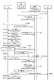
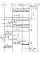
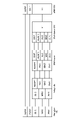
- FIG. 1 is a sequence diagram showing an example of a UE positioning sequence in which a base station notifies the LMF of a combination of a position of its own base station and time information according to the first embodiment.
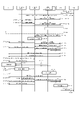
- the first embodiment it is a sequence diagram which showed the other example of the positioning sequence of the UE which notifies the LMF from the combination of the position and time information of the own base station from a base station.
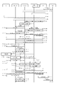
- the first modification of the first embodiment in the UE positioning sequence when the base station has an LMF, an operation of notifying the serving base station of the combination of the position and time information of the own base station from the peripheral base station is performed. It is a sequence diagram which shows.
- the serving base station in the UE positioning sequence when the UE has an LMF, the serving base station notifies the UE of the combination of the position and time information in the own base station and the peripheral base stations. It is a sequence diagram which shows the operation.
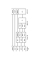
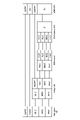
- FIG. 2 is a sequence diagram showing an example of a UE positioning sequence including a process of notifying the position of the own DU from the DU to the CU with respect to the second embodiment.
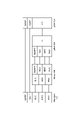
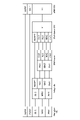
- FIG. 3 is a sequence diagram showing an example of a positioning sequence of an IAB node for the third embodiment. It is a sequence diagram which shows an example of the positioning sequence when the positioning of the IAB node and the UE is performed at the same time about the third embodiment.
- FIG. 4 is a diagram showing an example of a protocol stack in the case where the CU has an adaptation layer for the fourth embodiment.
- FIG. 4 is a diagram showing an example of a protocol stack in the case where the DU has an adaptation layer for the fourth embodiment.
- FIG. 5 is a diagram showing an example of a protocol stack in the case where the BAP is arranged above the adaptation layer for the first modification of the fourth embodiment. It is a figure which shows an example of the protocol stack in the case where the adaptation layer is arranged above BAP about the modification 1 of Embodiment 4.
- FIG. 5 is a diagram showing another example of the protocol stack in the case where the adaptation layer is arranged above the BAP for the modification 1 of the fourth embodiment.
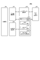
- FIG. 2 is a block diagram showing the overall configuration of the LTE communication system 200 discussed in 3GPP.
- the radio access network is referred to as E-UTRAN (Evolved Universal Terrestrial Radio Access Network) 201.
- the mobile terminal device (hereinafter referred to as "Mobile terminal (User Equipment: UE)") 202, which is a communication terminal device, can wirelessly communicate with the base station device (hereinafter referred to as "base station (E-UTRAN NodeB: eNB)”) 203. Yes, signals are sent and received by wireless communication.
- base station E-UTRAN NodeB: eNB
- the “communication terminal device” includes not only mobile terminal devices such as mobile mobile phone terminal devices but also non-moving devices such as sensors.
- the “communication terminal device” may be simply referred to as a "communication terminal”.
- Control protocols for mobile terminals 202 such as RRC (Radio Resource Control) and user planes (hereinafter sometimes referred to as U-Plane), such as PDCP (Packet Data Convergence Protocol), RLC (Radio Link Control), MAC (Medium). If Access Control) and PHY (Physical layer) are terminated at base station 203, E-UTRAN is composed of one or more base stations 203.
- RRC Radio Resource Control
- U-Plane User Plane
- PDCP Packet Data Convergence Protocol
- RLC Radio Link Control
- MAC Medium
- E-UTRAN is composed of one or more base stations 203.
- the control protocol RRC Radio Resource Control
- the states of the base station 203 and the mobile terminal 202 in the RRC include RRC_IDLE and RRC_CONTECTED.
- RRC_IDLE PLMN (Public Land Mobile Network) selection, system information (System Information: SI) notification, paging (paging), cell re-selection (cell re-selection), mobility, etc. are performed.
- RRC_CONCEPTED the mobile terminal has an RRC connection and can send and receive data to and from the network. Further, in RRC_CONCEPTED, handover (HO), measurement of an adjacent cell (Neighbor cell), and the like are performed.
- Base station 203 is composed of one or more eNBs 207.
- EPC Evolved Packet Core
- EPS Evolved Packet System
- the EPC, which is a core network, and the E-UTRAN201, which is a wireless access network, may be collectively referred to as a "network".
- the eNB 207 is a mobility management Entity (MME), an S-GW (Serving Gateway), or an MME / S-GW unit (hereinafter, may be referred to as “MME unit”) 204 including MME and S-GW. It is connected by the S1 interface, and control information is communicated between the eNB 207 and the MME unit 204.
- MME unit mobility management Entity
- a plurality of MME units 204 may be connected to one eNB 207.
- the eNBs 207 are connected by an X2 interface, and control information is communicated between the eNBs 207s.
- the MME unit 204 controls the connection between the eNB 207, which is a higher-level device, specifically a higher-level node and is a base station, and the mobile terminal (UE) 202.
- the MME unit 204 constitutes an EPC which is a core network.
- Base station 203 constitutes E-UTRAN 201.
- the base station 203 may be configured as one cell or may be configured as a plurality of cells. Each cell has a predetermined range as a coverage that can communicate with the mobile terminal 202, and wirelessly communicates with the mobile terminal 202 within the coverage. When one base station 203 constitutes a plurality of cells, each cell is configured to be communicable with the mobile terminal 202.
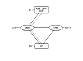
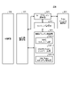
- FIG. 3 is a block diagram showing the overall configuration of the 5G communication system 210 discussed in 3GPP.
- the radio access network is referred to as NG-RAN (Next Generation Radio Access Network) 211.
- the UE 202 can wirelessly communicate with the NR base station apparatus (hereinafter referred to as "NR base station (NG-RAN NodeB: gNB)") 213, and transmits and receives signals by wireless communication.
- NR base station (NG-RAN NodeB: gNB) NR base station
- the core network is also referred to as a 5G core (5G Core: 5GC).
- 5G Core 5G Core
- Control protocols for the UE 202 such as RRC (Radio Resource Control) and user planes (hereinafter sometimes referred to as U-Plane), such as SDAP (Service Data Adaptation Protocol), PDCP (Packet Data Convergence Protocol), RLC (Radio Link). If Control), MAC (Medium Access Control), and PHY (Physical layer) are terminated at NR base station 213, NG-RAN is composed of one or more NR base stations 213.
- RRC Radio Resource Control
- U-Plane user planes
- SDAP Service Data Adaptation Protocol
- PDCP Packet Data Convergence Protocol
- RLC Radio Link
- MAC Medium Access Control
- PHY Physical layer
- the function of the control protocol RRC (Radio Resource Control) between the UE 202 and the NR base station 213 is the same as that of LTE.
- the states of the NR base station 213 and the UE 202 in the RRC include RRC_IDLE, RRC_CONTECTED, and RRC_INACTIVE.
- RRC_IDLE and RRC_CONTECTED are the same as the LTE method.
- RRC_INACTIVE system information (System Information: SI) notification, paging, cell re-selection, mobility, etc. are performed while the connection between the 5G core and the NR base station 213 is maintained. ..
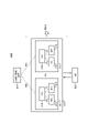
- gNB217 is an access / mobility management function (Access and Mobility Management Function: AMF), a session management function (Session Management Function: SMF), or UPF (User Plane Function), or AMF / SMF / UPF including AMF, SMF, and UPF.
- the unit (hereinafter sometimes referred to as “5GC unit”) 214 is connected to the unit by an NG interface. Control information and / or user data is communicated between the gNB 217 and the 5GC unit 214.
- the NG interface is a general term for the N2 interface between gNB217 and AMF, the N3 interface between gNB217 and UPF, the N11 interface between AMF and SMF, and the N4 interface between UPF and SMF.
- a plurality of 5GC units 214 may be connected to one gNB 217.
- the gNB 217s are connected by an Xn interface, and control information and / or user data are communicated between the gNB 217s.
- the 5GC unit 214 is a higher-level device, specifically, a higher-level node, and distributes a paging signal to one or more base stations 203 and / or base stations 213. Further, the 5GC unit 214 performs mobility control (MobilityControl) in the standby state (Idle State). The 5GC unit 214 manages the tracking area list when the mobile terminal 202 is in the standby state, the inactive state (Inactive State), and the active state (Active State). The 5GC unit 214 starts the paging protocol by transmitting a paging message to a cell belonging to the tracking area (tracking area) in which the mobile terminal 202 is registered.
- MobilityControl mobility control
- the 5GC unit 214 starts the paging protocol by transmitting a paging message to a cell belonging to the tracking area (tracking area) in which the mobile terminal 202 is registered.
- the NR base station 213 may also form one or a plurality of cells like the base station 203. When one NR base station 213 constitutes a plurality of cells, each cell is configured to be communicable with the UE 202.
- the gNB 217 may be divided into a central unit (Central Unit: hereinafter, may be referred to as CU) 218 and a distributed unit (Distributed Unit: hereinafter, may be referred to as DU) 219.
- CU central unit
- DU distributed unit
- One CU218 is configured in gNB217.
- DU219 is composed of one or more in gNB217.
- the CU 218 is connected to the DU 219 by an F1 interface, and control information and / or user data is communicated between the CU 218 and the DU 219.
- the integrated data management (UDM) function and the policy control function (Policy Control Function: PCF) described in Non-Patent Document 21 (3GPP TS23.501) may be included.
- UDM and / or PCF may be included in 5GC section 214 in FIG.
- the location management function (LMF) described in Non-Patent Document 24 (3GPP TS38.305) may be provided.
- the LMF may be connected to the base station via the AMF as disclosed in Non-Patent Document 30 (3GPP TS23.263).
- the non-3GPP interworking function (N3IWF) described in Non-Patent Document 21 (3GPP TS23.501) may be included.
- the N3IWF may terminate the access network (AN) with the UE in non-3GPP access with the UE.
- FIG. 4 is a diagram showing a configuration of DC by eNB and gNB connected to EPC.
- the solid line shows the connection of U-Plane
- the broken line shows the connection of C-Plane.
- eNB223-1 is a master base station
- gNB224-2 is a secondary base station (this DC configuration may be referred to as EN-DC).
- FIG. 4 shows an example in which a U-Plane connection between the MME unit 204 and gNB224-2 is performed via eNB223-1, but even if the U-Plane connection is performed directly between the MME unit 204 and gNB224-2. good.
- FIG. 5 is a diagram showing the configuration of DC by gNB connected to the NG core.
- the solid line shows the connection of U-Plane
- the broken line shows the connection of C-Plane.
- gNB224-1 is a master base station
- gNB224-2 is a secondary base station (this DC configuration may be referred to as NR-DC).
- FIG. 5 shows an example in which the U-Plane connection between the 5GC unit 214 and gNB224-2 is performed via gNB224-1, but even if the U-Plane connection is performed directly between the 5GC unit 214 and gNB224-2. good.
- FIG. 6 is a diagram showing the configuration of DC by eNB and gNB connected to the NG core.
- the solid line shows the connection of U-Plane
- the broken line shows the connection of C-Plane.
- eNB 226-1 is a master base station
- gNB 224-2 is a secondary base station (this DC configuration may be referred to as NG-EN-DC).
- FIG. 6 shows an example in which the U-Plane connection between the 5GC unit 214 and the gNB 224-2 is performed via the eNB 226-1, but even if the U-Plane connection is performed directly between the 5GC unit 214 and the gNB 224-2. good.
- FIG. 7 is a diagram showing other configurations of DC by eNB and gNB connected to the NG core.
- the solid line shows the connection of U-Plane
- the broken line shows the connection of C-Plane.
- gNB224-1 is a master base station
- eNB226-2 is a secondary base station (this DC configuration may be referred to as NE-DC).
- FIG. 7 shows an example in which the U-Plane connection between the 5GC unit 214 and the eNB 226-2 is performed via gNB224-1, but even if the U-Plane connection is performed directly between the 5GC unit 214 and the eNB 226-2. good.
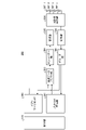
- FIG. 8 is a block diagram showing the configuration of the mobile terminal 202 shown in FIG. The transmission process of the mobile terminal 202 shown in FIG. 8 will be described.
- the control data from the protocol processing unit 301 and the user data from the application unit 302 are stored in the transmission data buffer unit 303.
- the data stored in the transmission data buffer unit 303 is passed to the encoder unit 304 and subjected to encoding processing such as error correction.
- the data encoded by the encoder unit 304 is modulated by the modulation unit 305. Precoding in MIMO may be performed in the modulation unit 305.
- the modulated data is converted into a baseband signal, then output to the frequency conversion unit 306, and converted into a radio transmission frequency. After that, the transmission signal is transmitted from the antennas 307-1 to 307-4 to the base station 203.
- the reception process of the mobile terminal 202 is executed as follows.
- the radio signal from the base station 203 is received by the antennas 307-1 to 307-4.
- the received signal is converted from the radio reception frequency into a baseband signal by the frequency conversion unit 306, and demodulation processing is performed by the demodulation unit 308.
- the demodulation unit 308 may perform weight calculation and multiplication processing.
- the demodulated data is passed to the decoder unit 309, and decoding processing such as error correction is performed.
- the control data is passed to the protocol processing unit 301, and the user data is passed to the application unit 302. A series of processes of the mobile terminal 202 is controlled by the control unit 310. Therefore, although the control unit 310 is omitted in FIG.
- the control unit 310 is realized by, for example, a processing circuit including a processor and a memory. That is, the control unit 310 is realized by the processor executing a program in which a series of processes of the mobile terminal 202 is described. A program in which a series of processes of the mobile terminal 202 is described is stored in a memory. Examples of memory are non-volatile or volatile semiconductor memories such as RAM (Random Access Memory), ROM (Read Only Memory), and flash memory.
- the control unit 310 may be realized by a dedicated processing circuit such as FPGA (Field Programmable Gate Array), ASIC (Application Specific Integrated Circuit), DSP (Digital Signal Processor). In FIG. 8, the number of antennas used by the mobile terminal 202 for transmission and the number of antennas used for reception may be the same or different.
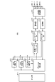
- FIG. 9 is a block diagram showing the configuration of the base station 203 shown in FIG. The transmission process of the base station 203 shown in FIG. 9 will be described.
- the EPC communication unit 401 transmits / receives data between the base station 203 and the EPC (MME unit 204, etc.).
- the 5GC communication unit 412 transmits / receives data between the base station 203 and the 5GC (5GC unit 214, etc.).
- the other base station communication unit 402 transmits / receives data to / from another base station.
- the EPC communication unit 401, 5GC communication unit 412, and other base station communication unit 402 each exchange information with the protocol processing unit 403.
- the control data from the protocol processing unit 403, and the user data and control data from the EPC communication unit 401, 5GC communication unit 412, and the other base station communication unit 402 are stored in the transmission data buffer unit 404.
- the data stored in the transmission data buffer unit 404 is passed to the encoder unit 405 and subjected to encoding processing such as error correction. There may be data directly output from the transmission data buffer unit 404 to the modulation unit 406 without performing the encoding process.
- the encoded data is modulated by the modulation unit 406. Precoding in MIMO may be performed in the modulation unit 406.
- the modulated data is converted into a baseband signal, then output to the frequency conversion unit 407, and converted into a radio transmission frequency. After that, the transmission signal is transmitted from the antennas 408-1 to 408-4 to one or more mobile terminals 202. In FIG. 9, the case where the number of antennas is four is illustrated, but the number of antennas is not limited to four.
- the reception process of the base station 203 is executed as follows.
- a radio signal from one or more mobile terminals 202 is received by the antenna 408.
- the received signal is converted from the radio reception frequency into a baseband signal by the frequency conversion unit 407, and demodulation processing is performed by the demodulation unit 409.
- the demodulated data is passed to the decoder unit 410, and decoding processing such as error correction is performed.
- the control data is passed to the protocol processing unit 403 or 5GC communication unit 412 or EPC communication unit 401 or other base station communication unit 402, and the user data is passed to the 5GC communication unit 412 or EPC communication unit 401 or other base. It is passed to the station communication unit 402.
- a series of processes of the base station 203 is controlled by the control unit 411. Therefore, although the control unit 411 is omitted in FIG. 9, it is connected to each unit 401 to 410, 412.
- the control unit 411 is realized by a processing circuit including a processor and a memory, or a dedicated processing circuit such as an FPGA, an ASIC, or a DSP, similarly to the control unit 310 of the mobile terminal 202 described above.
- the number of antennas used by the base station 203 for transmission and the number of antennas used for reception may be the same or different.
- FIG. 9 is a block diagram showing the configuration of the base station 203, but the base station 213 may have the same configuration. Further, with respect to FIGS. 8 and 9, the number of antennas of the mobile terminal 202 and the number of antennas of the base station 203 may be the same or different.
- FIG. 10 is a block diagram showing the configuration of the MME.
- FIG. 10 shows the configuration of the MME 204a included in the MME unit 204 shown in FIG. 2 described above.
- the PDN GW communication unit 501 transmits / receives data between the MME 204a and the PDN GW (Packet Data Network Gate Way).
- the base station communication unit 502 transmits / receives data by the S1 interface between the MME 204a and the base station 203.
- the data received from the PDN GW is user data
- the user data is passed from the PDN GW communication unit 501 to the base station communication unit 502 via the user plane communication unit 503 and to one or more base stations 203. Will be sent.
- the user data is passed from the base station communication unit 502 to the PDN GW communication unit 501 via the user plane communication unit 503 and transmitted to the PDN GW.
- control data is passed from the PDN GW communication unit 501 to the control plane control unit 505.
- control data is passed from the base station communication unit 502 to the control plane control unit 505.
- the HeNBGW communication unit 504 transmits / receives data between the MME204a and the HeNB GW (Home-eNB Gate Way).
- the control data received by the HeNBGW communication unit 504 from the HeNB GW is passed to the control plane control unit 505.
- the HeNBGW communication unit 504 transmits the control data input from the control plane control unit 505 to the HeNB GW.
- the control plane control unit 505 includes a NAS security unit 505-1, a SAE bearer control unit 505-2, an idle state mobility management unit 505-3, and the like, and is referred to as a control plane (hereinafter referred to as C-Plane). In some cases), perform all processing.
- the NAS security unit 505-1 performs security of NAS (Non-Access Stratum) messages and the like.
- the SAE bearer control unit 505-2 manages the bearers of the SAE (System Architecture Evolution).
- the idle state mobility management unit 505-3 manages the mobility of the standby state (Idle State: LTE-IDLE state, or simply referred to as idle), generates and controls the paging signal in the standby state, and is under the umbrella of the idle state mobility management unit 505-3. Addition, deletion, update, search, tracking area list management, etc. of the tracking area of one or more mobile terminals 202.
- the standby state Idle State: LTE-IDLE state, or simply referred to as idle
- MME204a distributes the paging signal to one or more base stations 203.
- MME204a performs mobility control in the standby state (Idle State).
- the MME204a manages the tracking area list when the mobile terminal 202 is in the standby state and when it is in the active state (Active State).
- the MME204a starts the paging protocol by transmitting a paging message to a cell belonging to the tracking area (tracking area) in which the mobile terminal 202 is registered.
- the management of the CSG of the eNB 207 connected to the MME 204a, the management of the CSG ID, and the management of the whitelist may be performed by the idle state mobility management unit 505-3.
- control unit 506 A series of processes of MME204a is controlled by the control unit 506. Therefore, although the control unit 506 is omitted in FIG. 10, it is connected to each unit 501 to 505.
- the control unit 506 is realized by a processing circuit including a processor and a memory, or a dedicated processing circuit such as an FPGA, an ASIC, or a DSP, similarly to the control unit 310 of the mobile terminal 202 described above.
- FIG. 11 is a block diagram showing the configuration of the 5GC unit.
- FIG. 11 shows the configuration of the 5GC unit 214 shown in FIG. 3 described above.
- FIG. 11 shows a case where the 5GC unit 214 shown in FIG. 5 includes an AMF configuration, an SMF configuration, and an UPF configuration.
- the Data Network communication unit 521 transmits / receives data between the 5GC unit 214 and the Data Network.
- the base station communication unit 522 transmits / receives data via the S1 interface between the 5GC unit 214 and the base station 203, and / or the NG interface between the 5GC unit 214 and the base station 213.
- the user data is passed from Data Network communication unit 521 to base station communication unit 522 via user plain communication unit 523, and one or more base stations 203. And / or transmitted to base station 213.
- the user data is passed from the base station communication unit 522 to the Data Network communication unit 521 via the user plain communication unit 523, and is passed to the Data Network communication unit 521. Will be sent to.
- control data When the data received from the Data Network is control data, the control data is passed from the Data Network communication unit 521 to the session management unit 527 via the user plane communication unit 523.
- the session management unit 527 passes the control data to the control plane control unit 525.
- the control data When the data received from the base station 203 and / or the base station 213 is control data, the control data is passed from the base station communication unit 522 to the control plane control unit 525.
- the control plane control unit 525 passes the control data to the session management unit 527.
- the control plane control unit 525 includes a NAS security unit 525-1, a PDU session control unit 525-2, an idle state mobility management unit 525-3, and the like, and may be referred to as a control plane (hereinafter, also referred to as C-Plane). Performs all processing for (is).
- the NAS security unit 525-1 performs security of NAS (Non-Access Stratum) messages and the like.
- the PDU session control unit 525-2 manages the PDU session between the mobile terminal 202 and the 5GC unit 214.
- the idle state mobility management unit 525-3 manages the mobility of the standby state (idle state (Idle State): RRC_IDLE state, or simply also referred to as idle), generates and controls the paging signal in the standby state, and is one under the umbrella. Addition, deletion, update, search, tracking area list management, etc. of the tracking area of one or more mobile terminals 202 are performed.
- a series of processes of the 5GC unit 214 is controlled by the control unit 526. Therefore, although the control unit 526 is omitted in FIG. 11, it is connected to each unit 521 to 523, 525, 527.
- the control unit 526 is realized by a processing circuit including a processor and a memory, or a dedicated processing circuit such as an FPGA, an ASIC, or a DSP, similarly to the control unit 310 of the mobile terminal 202 described above.
- FIG. 12 is a flowchart showing an outline from a cell search to a standby operation performed by a communication terminal (UE) in an LTE communication system.
- the communication terminal starts the cell search, in step ST601, the slot timing and the frame are used by using the first synchronization signal (P-SS) and the second synchronization signal (S-SS) transmitted from the surrounding base stations. Synchronize the timing.
- P-SS first synchronization signal
- S-SS second synchronization signal
- the P-SS and S-SS are collectively called a synchronization signal (SS).
- a synchronization code corresponding to one-to-one is assigned to the PCI assigned to each cell in the synchronization signal (SS).
- the number of PCIs is considered to be 504.
- the communication terminal synchronizes using the 504 ways of PCI, and detects (identifies) the PCI of the synchronized cell.
- the communication terminal then receives a cell-specific reference signal (CRS), which is a reference signal (reference signal: RS) transmitted from the base station for each cell to the synchronized cell in step ST602. ) Is detected, and the received power of RS (Reference Signal Received Power: RSRP) is measured.
- CRS cell-specific reference signal
- RS Reference Signal Received Power
- RS Reference Signal Received Power
- RS Reference Signal Received Power
- step ST603 the communication terminal selects the cell having the highest RS reception quality, for example, the cell having the highest RS reception power, that is, the best cell, from among the one or more cells detected up to step ST602. select.
- the communication terminal receives the best cell PBCH and obtains the BCCH which is the broadcast information.
- a MIB Master Information Block
- the MIB information includes, for example, a DL (downlink) system bandwidth (also called a transmission bandwidth configuration (dl-bandwidth)), the number of transmission antennas, and an SFN (System Frame Number).
- the communication terminal receives the DL-SCH of the cell based on the cell configuration information of the MIB, and obtains the SIB (System Information Block) 1 in the broadcast information BCCH.
- the SIB 1 includes information on access to the cell, information on cell selection, and scheduling information on another SIB (SIBk; an integer of k ⁇ 2). Further, SIB1 includes a tracking area code (Tracking Area Code: TAC).
- the communication terminal compares the TAC of SIB1 received in step ST605 with the TAC portion of the tracking area identifier (Tracking Area Identity: TAI) in the tracking area list already owned by the communication terminal. ..
- the tracking area list is also referred to as a TAI list (TAI list).
- TAI is identification information for identifying a tracking area, and is composed of MCC (Mobile Country Code), MNC (Mobile Network Code), and TAC (Tracking Area Code).
- MCC Mobile Country Code
- MNC Mobile Network Code
- TAC Track Area Code
- MCC Mobile Country Code
- MNC Mobile Network Code
- TAC Track Area Code
- step ST606 if the TAC received in step ST605 is the same as the TAC included in the tracking area list, the communication terminal enters the standby operation in the cell. In comparison, if the TAC received in step ST605 is not included in the tracking area list, the communication terminal passes through the cell to the core network (Core Network, EPC) including the MME and the like, and TAU (Tracking Area Update). Request a change in the tracking area to do this.
- the core network Core Network, EPC
- MME Management Entity
- the best beam may be selected in addition to the best cell in step ST603.
- the beam information for example, the beam identifier may be acquired in step ST604.
- the scheduling information of Remaining Minimum SI may be acquired in step ST604.
- RMSI Remaining Minimum SI
- the device constituting the core network tracks based on the identification number (UE-ID, etc.) of the communication terminal sent from the communication terminal together with the TAU request signal. Update the area list.
- the core network side device transmits the updated tracking area list to the communication terminal.
- the communication terminal rewrites (updates) the TAC list held by the communication terminal based on the received tracking area list. After that, the communication terminal enters the standby operation in the cell.
- the cell composed of eNB has a relatively wide range of coverage.
- cells are configured to cover an area with a relatively wide range of coverage of the plurality of cells composed of the plurality of eNBs.
- the cell composed of eNB has a narrow range of coverage as compared with the coverage of the conventional cell composed of eNB. Therefore, as in the conventional case, in order to cover a certain area, a large number of small-celled eNBs are required as compared with the conventional eNBs.
- macro cells cells having relatively large coverage, such as cells composed of conventional eNBs, are referred to as “macro cells”, and eNBs constituting macro cells are referred to as “macro eNBs”.
- a cell having a relatively small coverage such as a cell made into a small cell, is referred to as a "small cell”, and an eNB constituting the small cell is referred to as a "small eNB”.
- the macro eNB may be, for example, a "Wide Area Base Station" described in Non-Patent Document 7.
- the small eNB may be, for example, a low power node, a local area node, a hotspot, or the like.
- the small eNB is a pico eNB that constitutes a pico cell, a femto eNB that constitutes a femto cell, a HeNB, an RRH (Remote Radio Head), an RRU (Remote Radio Unit), an RRE (Remote Radio Equipment), or an RN (Relay Node).
- the small eNB may be a "Local Area Base Station" or a "Home Base Station" described in Non-Patent Document 7.
- FIG. 13 shows an example of the cell configuration in NR.
- a narrow beam is formed and transmitted in a different direction.
- the base station 750 uses the beam 751-1 to transmit and receive to and from a mobile terminal at a certain time. At other times, the base station 750 uses the beam 751-2 to transmit and receive to and from the mobile terminal.
- the base station 750 uses one or more of the beams 751-3 to 751-8 to transmit and receive to and from the mobile terminal. By doing so, the base station 750 constitutes a wide range of cells.
- FIG. 13 shows an example in which the number of beams used by the base station 750 is 8, but the number of beams may be different from 8. Further, in the example shown in FIG. 13, the number of beams used simultaneously by the base station 750 is set to one, but may be a plurality.
- SL Side Link
- D2D Device to Device
- V2V Vehicle to Vehicle
- the physical channel used for SL (see Non-Patent Document 1) will be described.
- the physical sidelink broadcast channel (PSBCH) carries information related to synchronization with the system and is transmitted from the UE.
- the physical sidelink discovery channel (PSDCH: Physical sidelink discovery channel) carries sidelink discovery messages from the UE.
- the physical sidelink control channel (PSCCH: Physical sidelink control channel) carries control information from the UE for sidelink communication and V2X sidelink communication.
- the physical sidelink shared channel (PSSCH: Physical sidelink shared channel) carries data from the UE for sidelink communication and V2X sidelink communication.
- the physical sidelink feedback channel (PSFCH: Physical sidelink feedback channel) carries HARQ feedback on the sidelink from the UE that received the PSCH transmission to the UE that transmitted the PSCH.
- the transport channel used for SL (see Non-Patent Document 1) will be described.
- the side link broadcast channel (SL-BCH: Sidelink broadcast channel) has a predetermined transport format and is mapped to the PSBCH which is a physical channel.
- the Sidelink Discovery Channel (SL-DCH: Sidelink discovery channel) has a fixed size, periodic notification transmission in a predetermined format.
- SL-DCH also supports both UE automatic resource selection and resource allocation scheduled by eNB. There is a risk of collision in UE automatic resource selection, and there is no collision when the UE allocates individual resources by eNB.
- SL-DCH also supports HARQ combining, but not HARQ feedback.
- SL-DCH is mapped to PSDCH, which is a physical channel.
- SL-SCH Sidelink shared channel
- SL-SCH Sidelink shared channel
- SL-SCH supports broadcast transmission.
- SL-SCH supports both UE automatic resource selection and resource allocation scheduled by eNB. There is a risk of collision in UE automatic resource selection, and there is no collision when the UE allocates individual resources by eNB.
- SL-SCH also supports HARQ combining, but not HARQ feedback.
- the SL-SCH also supports dynamic link adaptation by changing the transmit power, modulation, and coding.
- SL-SCH is mapped to PSSCH which is a physical channel.
- the side link notification control channel (SBCCH: Sidelink Broadcast Control Channel) is a side link channel for transmitting side link system information from one UE to another UE.
- the SBCCH is mapped to the transport channel SL-BCH.
- the side link traffic channel (STCH: Sidelink Traffic Channel) is a one-to-many side link traffic channel for transmitting user information from one UE to another UE.
- STCH is used only by UEs with side-link communication capabilities and UEs with V2X side-link communication capabilities.
- One-to-one communication between UEs with two side-link communication capabilities is also realized in STCH.
- the STCH is mapped to the transport channel SL-SCH.
- the side link control channel (SCCH: Sidelink Control Channel) is a side link control channel for transmitting control information from one UE to another UE.
- the SCCH is mapped to the transport channel SL-SCH.
- V2X communication In 3GPP, it is being considered to support V2X communication even in NR.
- the study of V2X communication in NR is proceeding based on the LTE system and the LTE-A system, but changes and additions from the LTE system and the LTE-A system are made in the following points.
- PC5-S signaling is being studied in order to support unicast and groupcast in addition to broadcast in SL communication (see Non-Patent Document 22 (3GPP TS23.287)).
- PC5-S signaling is performed to establish SL, a link for performing PC5 communication.
- the link is performed on the V2X layer and is also referred to as a layer 2 link.
- RRC signaling in SL communication is also referred to as PC5 RRC signaling.
- PC5 RRC signaling it has been proposed to notify the capabilities of UEs among UEs that perform PC5 communication, and to notify the setting of an AS layer for performing V2X communication using PC5 communication.
- the UE positioning may be performed using positioning signal transmission / reception between the base station and the UE.
- the downlink positioning signal may be, for example, a PRS (Positioning Reference Signal), an SS block, a DM-RS, or a PTRS.
- the upstream positioning signal may be, for example, SRS (Sounding Reference Signal), PRACH, DM-RS, or PTRS.
- the base station may transmit a downlink positioning signal to the UE.
- the UE may transmit an uplink positioning signal to the base station.
- the downlink positioning signal transmission from the base station and the uplink positioning signal transmission from the UE may be performed independently.
- the UE may transmit the uplink positioning signal triggered by the reception of the downlink positioning signal from the base station.
- the base station may transmit the downlink positioning signal triggered by the reception of the uplink positioning signal from the UE.
- the UE may notify the LMF of the downlink positioning signal reception result.
- the reception result of the downlink positioning signal may include, for example, information regarding the propagation delay of the downlink positioning signal, or information regarding the arrival direction of the downlink positioning signal.
- the UE may transmit information to the LMF regarding the time difference between receiving the downlink positioning signal and transmitting the uplink positioning signal, or may transmit information regarding the uplink positioning signal transmission time. Alternatively, information regarding the downlink positioning signal reception time may be transmitted.
- the base station may notify the LMF of the uplink positioning signal reception result.
- the reception result of the uplink positioning signal may include, for example, information regarding the propagation delay of the uplink positioning signal, or information regarding the arrival direction of the uplink positioning signal.
- the base station may notify the LMF of information regarding the downlink positioning signal transmission time, may transmit information regarding the uplink positioning signal reception time, or may receive the uplink positioning signal. Information regarding the time difference between the transmission of the downlink positioning signal and the transmission of the downlink positioning signal may be transmitted.
- the LMF may derive the position of the UE using the above-mentioned information from the UE and / or the base station.
- the base station may be stationary or may be moving.
- the base station notifies the LMF of information regarding the location of its own base station. You may notify the time information. The base station may send the information to the LMF once or multiple times.
- the base station may notify the LMF of information in which the position of the base station and the time information are associated with each other.
- the LMF may use the information to calculate the position of the UE. As a result, for example, since the position of the base station at that time is known, the LMF can accurately calculate the position of the UE.
- the information in (1) above may be, for example, an identifier of a base station.
- the information of the identifier may be, for example, gNB-ID.
- the LMF may use the information to identify the base station from which the notification is made. This allows, for example, the LMF to easily identify the base station that is the source of the notification, and as a result, the positioning procedure in the communication system can be quickly executed.
- the information in (2) above may include, for example, information indicating the position of the base station.
- the information indicating the position of the base station may be, for example, information indicating latitude, longitude, and / or altitude, or information indicating a relative position from a predetermined point. This allows, for example, the LMF to reduce errors in the UE position calculation.
- the information in (2) above may include information on the accuracy of the position of the base station.
- the information regarding accuracy may be provided, for example, regardless of the axis, or may be provided for each axis.
- accuracy may be given for each of latitude, longitude, and altitude, and even if accuracy in the horizontal direction, that is, the latitude / longitude direction and accuracy in the vertical direction, that is, the altitude direction are provided. good. This allows, for example, the LMF to derive accuracy in the UE position calculation.
- the information in (2) above may include, for example, information on the zone disclosed in Non-Patent Document 33 (3GPP TR37.985).
- the information regarding the zone may be one or plural.
- the LMF may use the information to change the base station used for positioning.
- the LMF may use a base station used for UE positioning as a base station belonging to the same zone. As a result, for example, it is possible to prevent the range in which the base station used for positioning exists from being unnecessarily increased, and as a result, it is possible to improve the positioning accuracy.
- the LMF may reassign the zone to the base station by using the information indicating the position of the base station and the information indicating the zone.
- the LMF may notify the base station of the information on the zone after reassignment.
- the base station may use the information to update the information of the zone of its own base station. This makes it possible to reduce interference with other UEs, for example, in side link communication performed by a UE under the base station.
- the information in (3) above may include information on the propagation delay of the positioning signal, information on the accuracy of the propagation delay, and information on the arrival angle of the positioning signal.
- Information on the accuracy of the arrival angle may be included, or information on the plurality of combinations described above may be included. This allows, for example, the LMF to quickly derive the position of the UE.
- the information in (4) above may include, for example, information regarding the time when the position of the base station is derived, information regarding the accuracy of the time, and transmission of a positioning signal to the UE.
- Information on the time accuracy may be included, information on the accuracy of the time may be included, information on the time when the positioning signal is received from the UE may be included, and information on the accuracy of the time. May be included, or information on the plurality of combinations described above may be included.
- the LMF may use the information to derive the position of the UE at a certain time.
- the LMF derives the position of the UE by using a combination of the time when the position of the base station is derived, the time when the positioning signal is transmitted to the UE, and the time when the time when the positioning signal is received from the UE is close to each other. You may. This allows, for example, the LMF to improve the accuracy of UE position derivation.
- the information in (5) above may be, for example, one-dimensional speed of the base station, horizontal speed, vertical speed, latitude, longitude, and / or altitude. It may be a speed in the direction.
- the LMF may use the information to calculate the position of the UE. This allows, for example, the LMF to improve the accuracy of UE position derivation.
- the information in (6) above may be, for example, the absolute value of the acceleration of the base station, the acceleration in each of the horizontal direction and the vertical direction, and the latitude, longitude, and / or altitude direction. It may be acceleration.
- the LMF may use the information to calculate the position of the UE. This allows, for example, the LMF to improve the accuracy of UE position derivation.
- the above-mentioned information (7) may be, for example, information indicating a positioning method using radio waves of a communication system.
- the positioning method may be, for example, OTDOA (Observed Time Difference Of Arrival) or E-CID (Enhanced Cell ID) disclosed in Non-Patent Document 24 (3GPP TS38.305). It may be NR E-CID, or it may be a multi-RTT (Multi-RTT) that uses a round-trip propagation delay time (Round-Trip Time: RTT) between each of the multiple base stations and the UE. It may be DL-AoD (Downlink Angle of Departure), DL-TDOA (Downlink Time Difference Of Arrival), or UL-TDOA (Uplink Time Difference Of Arrival).
- DL-AoD Downlink Angle of Departure
- DL-TDOA Downlink Time Difference Of Arrival
- UL-TDOA Uplink Time Difference Of Arrival
- the above-mentioned information (7) may be positioning using GNSS (Global Navigation Satellite System), positioning using a pressure sensor, or WLAN (Wireless Local Area). Positioning may be performed using Network), positioning may be performed using Bluetooth (registered trademark) (Bluetooth), or positioning may be performed using a terrestrial beacon system (Terrestrial Beacon System). ..
- the LMF may use the information to acquire information about the positioning method of the UE. As a result, for example, the LMF can quickly acquire information on the positioning method of the UE, and as a result, the LMF can quickly perform the positioning of the UE.
- the information in (8) above may be information indicating the validity period of the notification from the base station to the LMF.
- the validity period may be determined, for example, by using the requirements for positioning of the UE (eg, accuracy) or by using the speed of the base station.
- the LMF may use the information to acquire a period during which the information regarding the position of the base station or the like is valid.
- the LMF may request the base station to notify the information such as the position when the valid period has expired.
- the base station may re-notify the LMF when the validity period has expired. This makes it possible to improve the positioning accuracy of the UE, for example.
- the information in (9) above may be information regarding the identifier of the UE to be positioned.
- the information regarding the identifier may be, for example, a UE-ID, or a Subscription Permanent Identifier (SUPI), a Subscription Concealed Identifier (SUCI), or a Permanent Equipment Identifier disclosed in Non-Patent Document 21 (3GPP TS23.501). It may be PEI) and / or 5G Globally Unique Temporary Identifier (5G-GUTI).
- the LMF may use the information to identify the UE. This allows the LMF to quickly identify the UE, for example, even when positioning of a plurality of UEs is performed.
- the above-mentioned information (10) may be, for example, the information obtained by replacing the base station with DU in the above-mentioned (1) to (8).
- the above-mentioned information (10) may be one, or may be included for a plurality of pieces, for example, the number of DUs. This makes it possible to improve the positioning accuracy of the UE even in a communication system using, for example, a base station having a configuration divided into a CU and a DU.
- the above-mentioned information (11) may be, for example, the information obtained by replacing the base station with TRP in the above-mentioned (1) to (8).
- the above-mentioned information (11) may be one, or may be included for a plurality of pieces, for example, the number of TRPs. This makes it possible to improve the positioning accuracy of the UE even in a communication system using, for example, a base station having a TRP.
- the information associated with the position of the base station and the time information may be included in the assistance data notification from gNB to the LMF disclosed in Non-Patent Document 24 (3GPP TS38.305).
- the assistance data notification may include the above-mentioned information (4). This makes it possible to reduce the amount of signaling between the base station and the LMF, for example.
- the information may be included in the notification of uplink information / UE setting data disclosed in Non-Patent Document 24 (3GPP TS38.305).
- the notification may include the information of (2) and (4) described above. As a result, for example, the same effect as described above can be obtained.
- the information may be included in the notification of the positioning signal reception result disclosed in Non-Patent Document 24 (3GPP TS38.305).
- the notification may include the information of (2) and (4) described above.
- the information in (4) may be, for example, information on the time when the position of the base station is acquired. As a result, for example, the same effect as described above can be obtained.
- new signaling may be provided to transmit the information.
- the new signaling may be, for example, TRP information update. This makes it possible to ensure backward compatibility in, for example, a communication system.
- the base station may notify the information associating the position of the own base station with the time information only once.
- a single notification may include only one associated information, or may include a plurality of the associated information.
- the time range included in the plurality of information may include the time for transmitting and receiving the positioning signal.
- the LMF can apply the interpolation processing instead of the extrapolation processing to the derivation of the position of the base station and / or the UE, and as a result, the accuracy of the position calculation can be improved.
- the time range included in the plurality of pieces of the information may not include the time for transmitting and receiving the positioning signal.
- the end point of the range may come before the end point of the time for transmitting and receiving the positioning signal. This makes it possible to reduce, for example, the delay in positioning.
- the base station may notify the information in which the position of the own base station and the time information are associated with each other multiple times.
- the notification may be given a plurality of times, for example, by specifying the number of times or by not specifying the number of times.
- the notification may be given multiple times, for example, periodically.
- Information on the number of times and / or the period may be determined in advance by the standard, may be determined by the LMF, may be determined by the AMF, or may be determined by the base station.
- the LMF and / or AMF may notify the base station of the information.
- the LMF may notify the base station of the information using LPP signaling and / or NRPPa signaling.
- the AMF may notify the base station of the information using NAS signaling.
- the base station may start the periodic notification before the positioning signal transmission / reception, may be started by the positioning signal transmission / reception start instruction from the LMF, or may be triggered by the positioning signal transmission / reception start instruction, or the uplink positioning signal transmission instruction to the UE. You may start later.
- the base station may terminate the periodic notification when the positioning signal transmission / reception with the UE is completed, or may be terminated when the positioning signal transmission / reception result notification to the LMF is triggered. This makes it possible to improve the positioning accuracy of the UE, for example.
- the base station may re-notify the LMF upon the expiration of the validity period of the notification to the LMF, or the position included in the previous notification.
- the notification may be given again when the position of the base station at the present time is separated by a predetermined value or more.
- the predetermined value described above may be determined using, for example, UE positioning requirements (eg, accuracy). This makes it possible to improve the accuracy of UE positioning, for example.
- the base station may give the notification triggered by a predetermined event.
- the base station may give the notification triggered by a positioning signal transmission / reception start instruction from the LMF, may be triggered by an uplink positioning signal transmission instruction to the UE, or may be triggered by a positioning signal transmission / reception with the UE. It may be performed with the completion as a trigger, may be performed with the notification of the positioning signal transmission / reception result to the LMF as a trigger, or may be performed with any one or more of the above. This makes it possible to reduce the amount of signaling between the base station and the LMF, for example.
- the notification of the information from the base station to the LMF may be autonomously sent from the base station to the LMF.
- the base station may give the notification in the wake of a predetermined event.
- the predetermined event may be, for example, reception of a positioning signal transmission / reception start instruction from the LMF, transmission of an uplink positioning signal transmission instruction to the UE, or completion of positioning signal transmission / reception with the UE. It may be the transmission of the positioning signal transmission / reception result notification to the LMF, or may be a plurality of the above. This makes it possible to reduce the amount of signaling between the base station and the LMF, for example.
- the LMF may request the base station to notify the information.
- the base station may notify the LMF of the information in the wake of the request.
- the LMF may request the base station to start notifying the information, or may request the base station to stop notifying the information.
- the base station may start the notification of the information or stop the notification of the information in the wake of the request. This makes it possible, for example, to avoid complexity in communication systems.
- the LMF may request the base station to notify a plurality of the information.
- the notification of the plurality of such information from the base station to the LMF may be performed at one time. This makes it possible to reduce the amount of signaling between the base station and the LMF, for example.
- the notification from the base station to the LMF may be divided into a plurality of times. The notification may be given periodically.
- (F) Information about the number of information included in the notification For example, the number of pieces of information on the combination of the position and time of the base station included in one notification.
- the base station may start the notification to the LMF by using the information regarding (A) described above. This makes it possible, for example, to avoid the design complexity of the process for initiating the notification at the base station.
- the base station may stop the notification to the LMF by using the information regarding (B) described above. This makes it possible to avoid, for example, the complexity of the design regarding the process for stopping the notification in the base station.
- the information shown in (C) above may be, for example, information indicating the range of time information notified from the base station to the LMF.
- the time information may be, for example, the information disclosed as (4) of the information notified by the base station to the LMF described above.
- the information shown in (C) above may include information indicating the start point of the range of the time information, information indicating the end point, and information indicating the period of the range. It may be.
- the base station may use the information shown in (C) above to determine the information to be included in the notification to the LMF. This makes it possible to prevent, for example, the excess or deficiency of information in the notification from the base station to the LMF.
- the information shown in (D) above may include, for example, the cycle of the notification from the base station to the LMF, the information of the offset with respect to the cycle, or both of the above. May be good.
- the offset may be given, for example, as a periodic remainder of the time at which the base station transmits the notification, or may be given with information at a certain transmission time.
- the offset may be given by information using time, or may be given by information using radio frame number, subframe number, slot number, and / or symbol number.
- the base station may use the information to give the notification to the LMF. This allows, for example, the LMF to track changes in the position of the base station, resulting in rapid calculation of the position of the UE.
- the information shown in (E) above may be, for example, once or a plurality of times.
- the value of (E) described above to a small value by the LMF
- the amount of signaling between the base station and the LMF can be reduced.
- the value of (E) described above to a large value by the LMF
- the position of the base station can be calculated with high accuracy, and as a result, the positioning accuracy of the UE position can be improved.
- the information shown in (F) above may be, for example, the number of information regarding the position included in one notification from the base station to the LMF.
- the value of the information may be 1 or 2 or more.
- the amount of processing in the base station can be reduced.
- the position of the base station at a certain time can be calculated with high accuracy, and as a result, the positioning accuracy of the UE position can be improved.
- the information shown in (G) above may include, for example, information regarding a positioning method required by the LMF from the base station.
- the information regarding the positioning method may be, for example, the same as the information disclosed as (7) of the information notified by the base station to the LMF described above. This makes it possible, for example, to improve flexibility in communication systems.
- the information shown in (H) above may be, for example, the information shown in (1) to (12) disclosed as an example of the information notified by the base station to the LMF.
- the base station may derive the information to be notified to the LMF by using the information of (H) described above. As a result, for example, the amount of signaling between the base station and the LMF can be reduced, and the amount of processing in the base station can be reduced.
- the information shown in (I) above may be, for example, information on positioning latency or information on positioning accuracy.
- the base station may, for example, use information about the accuracy of the positioning to determine whether to re-execute the notification to the LMF. For example, when the base station moves by a predetermined value or more from the position at the time of the previous notification, the LMF may be notified again.
- the above-mentioned predetermined value may be determined, for example, by using the accuracy requirement included in the above-mentioned (I). This makes it possible to improve the accuracy of UE positioning, for example.
- the information from the LMF to the base station may be included in the signaling of the assistance data request from the LMF to the gNB (eg, TRP information request) disclosed in Non-Patent Document 24 (3GPP TS38.305). This makes it possible to reduce the amount of signaling between the base station and the LMF, for example.
- the information may be included in the signaling of UL SRS setting request (eg, positioning information request) disclosed in Non-Patent Document 24 (3GPP TS38.305).
- UL SRS setting request eg, positioning information request
- 3GPP TS38.305 3GPP TS38.305
- the information may be included in the signaling of the positioning signal transmission / reception request (eg, Measurement request) disclosed in Non-Patent Document 24 (3GPP TS38.305).
- the positioning signal transmission / reception request eg, Measurement request
- 3GPP TS38.305 3GPP TS38.305
- new signaling may be provided to transmit the information. This makes it possible to ensure backward compatibility in, for example, a communication system.
- FIG. 14 is a sequence diagram showing an example of a UE positioning sequence in which a base station notifies the LMF of a combination of the position and time information of the own base station.
- FIG. 14 shows a case where a multi-RTT is used as the positioning method.
- the base station periodically notifies the LMF of the information of the combination of the position and the time information of the own base station.
- FIG. 14 shows a sequence example when the host device of the base station has a positioning function for deriving the position of the UE, that is, a sequence example when the host device operates as a positioning execution device.
- the AMF requests the LMF for the positioning service.
- the requirement may be, for example, a requirement for measuring the UE position.
- the AMF may make the request triggered by a request from a location service (LCS) client existing outside the 5G system, or may be triggered by a request from a UE, or the AMF spontaneously makes the request. You may go to the target.
- LCS location service
- the request from the LCS, UE, and / or AMF that resides outside the 5G system may include a request for information about the location of the base station to which the UE connects.
- the AMF may request the LMF for information regarding the location of the base station.
- the LCS can quickly grasp the position of the base station to which the UE is connected, and can quickly execute the processing in the location information service.
- the NWDAF Network Data Analytics Function disclosed in Non-Patent Document 21 (3GPP TS23.501) may request the LMF to provide information on the location of the UE and / or the base station.
- the request may be made via AMF.
- the AMF may perform the process of step ST1403 in the wake of the request from the NWDAF.
- it becomes possible to process the position information in the NWDAF and as a result, it becomes possible to reduce the processing amount of other devices in the communication network device.
- downlink PRS setting information is exchanged between the LMF and the serving base station.
- the signaling in procedure 1405 may be, for example, NRPPa signaling.
- the LMF requests TRP information from the serving base station.
- the serving base station notifies the LMF of the TRP information.
- Step ST1409 may include information about the identifier of the cell, DU, and / or TRP (hereinafter, may be referred to as a cell or the like) of the serving base station, or information about the timing of the cell or the like (eg, frame).
- Timing may be included, information regarding PRS settings such as cells may be included, and information regarding SS blocks such as cells, SS bursts (eg, information regarding frequency and / or time resources) may be included. It may include information about the PRS transmission direction from the cell or the like, or may include information about the position of the cell or the like.
- procedure 1410 shown in FIG. 14 the same processing as procedure 1405 is performed between the LMF and the peripheral base station.
- step ST1415 shown in FIG. 14 the serving base station and / or the peripheral base station notifies the LMF of the position and / or time information of the own base station.
- NRPPa signaling may be used for the notification in step ST1415.
- the information transmitted in step ST1415 may include the above-mentioned (1) to (12) disclosed as an example of the information notified by the base station to the LMF.
- the transmission of step ST1415 may be repeated.
- the LMF uses step ST1415 to acquire information about the location of serving base stations and / or peripheral base stations.
- the serving base station and / or the peripheral base station starts the notification of step ST1415 triggered by the procedure 1405 and / or the procedure 1410.
- a capability request and notification regarding positioning are made between the LMF and the UE.
- the signaling in procedure 1420 may be, for example, LPP signaling.
- the LMF requests the UE for capabilities regarding positioning.
- the UE notifies the LMF of the capabilities related to positioning.
- the LMF requests the serving base station for positioning information.
- the request may include a request for setting an uplink positioning signal, for example, an uplink SRS.
- the serving base station determines the uplink SRS resource of the UE.
- the serving base station sets the uplink SRS for the UE.
- the serving base station transmits a response to the positioning information request to the LMF.
- the response may include information about the UE's SRS settings, eg, SRS time and / or frequency resources.
- step ST1436 shown in FIG. 14 the LMF requests the serving base station to activate the SRS transmission of the UE.
- the serving base station requests the UE to activate SRS transmission.
- the UE starts transmission of SRS with step ST1437 as an opportunity.
- the LMF requests the serving base station and / or the peripheral base station to measure the positioning signal.
- NRPPa signaling may be used for the request.
- NRPPa MEASUREMENT REQUEST disclosed in Non-Patent Document 24 (3GPP TS38.305) may be used.
- the LMF notifies the UE of information used for positioning.
- the information may be, for example, information on the downlink PRS of the serving base station and / or the peripheral base station, information on the frame timing, or the combination described above.
- LPP signaling may be used for notification of the information.
- the LPP signaling may be, for example, the LPP Provide Assistance Data disclosed in Non-Patent Document 24 (3GPP TS38.305).
- the LMF requests the UE for positioning.
- LPP signaling may be used for the request.
- the LPP signaling may be, for example, the LPP Request Location Information disclosed in Non-Patent Document 24 (3GPP TS38.305).
- the UE performs PRS measurement processing according to the request.
- step ST1447 shown in FIG. 14 the UE requests the serving base station to set a measurement gap for transmitting and receiving positioning signals.
- RRC signaling for example, RRC Location Measurement Indication disclosed in Non-Patent Document 24 (3GPP TS38.305) may be used.
- the request may include information regarding the initiation of the positioning measurement gap.
- the serving base station instructs the UE to set the measurement gap.
- the UE sets the measurement gap according to the instruction in step ST1449.
- step ST1451 and step ST1453 shown in FIG. 14 the serving base station and the peripheral base station each transmit PRS to the UE.
- step ST1455 the UE performs PRS reception processing from the serving base station and / or the peripheral base station.
- the reception process includes a PRS measurement process.
- step ST1457 shown in FIG. 14 the UE transmits SRS to the serving base station.
- the serving base station processes the reception of SRS from the UE.
- the reception process includes an SRS measurement process.
- step ST1461 shown in FIG. 14 the UE transmits SRS to a peripheral base station.
- the peripheral base station performs SRS reception processing from the UE.
- the reception process includes an SRS measurement process.
- the UE notifies the LMF of information regarding the reception result of the positioning signal.
- LPP signaling may be used for the notification.
- the LPP signaling may be, for example, the LPP Provide Location Information disclosed in Non-Patent Document 24 (3GPP TS38.305).
- the serving base station and / or the peripheral base station notifies the LMF of information regarding the reception result of the positioning signal.
- NRPPa signaling may be used for the notification.
- NRPPa MEASUREMENT RESPONSE disclosed in Non-Patent Document 24 (3GPP TS38.305) may be used.
- the UE requests the serving base station to change the measurement gap.
- the request may be a request to return the measurement gap to the setting before positioning.
- RRC signaling for example, RRC Location Measurement Indication disclosed in Non-Patent Document 24 (3GPP TS38.305) may be used.
- the request may include information about stopping the positioning measurement gap.
- the serving base station instructs the UE to set the measurement gap.
- the UE changes the measurement gap setting according to the instruction in step ST1471.
- step ST1475 shown in FIG. 14 the position and / or time information of the own base station is transmitted from the serving base station and / or the peripheral base station to the LMF.
- the information transmitted in step ST1475 may be the same as in step ST1415.
- the LMF uses step ST1475 to acquire information about the location of serving base stations and / or peripheral base stations.
- the serving base station and / or the peripheral base station may end the periodic transmission shown in step ST1475, triggered by the notification of information regarding the reception result of the positioning signal shown in step ST1467.
- the signaling of step ST1467 transmitted after step ST1467 may be the final transmission process. This makes it possible to reduce the amount of signaling between the base station and the LMF, for example.
- step ST1479 shown in FIG. 14 the LMF calculates the position of the UE.
- Information from step ST1415, step ST1465, step ST1467, and / or step ST1475 may be used to calculate the UE position in the LMF.
- the LMF notifies the AMF of the calculated information regarding the UE position.
- the AMF may notify the UE of the information, may notify the LCS outside the 5G system, or may use the information in its own AMF.
- Step ST1481 shown in FIG. 14 may include information regarding the position and / or time of the base station.
- the AMF may notify the UE of information regarding the position and / or time of the base station, may notify the LCS outside the 5G system, or may be used in the own AMF. This allows, for example, the AMF to appropriately specify RNA and / or tracking areas for moving base stations.
- the LMF may notify the NWDAF of information about the location of the UE and / or the base station.
- the notification may be made via AMF.
- the LMF may give the notification to the NWDAF when the NWDAF requests the information.
- the NWDAF may use the information to perform data processing on location information. This makes it possible to reduce the amount of data processing of other devices in the communication network device, for example.
- FIG. 14 shows an example in which the serving base station and / or the peripheral base station starts the notification of step ST1415 triggered by the procedure 1405 and / or the procedure 1410, but other processing, for example, the positioning signal shown in step ST1440. It may be started with the measurement request of. As a result, for example, the processing of step ST1415 before the measurement request of the positioning signal becomes unnecessary, and as a result, the amount of signaling between the LMF and the base station can be reduced.
- step ST1415 and / or step ST1475 with respect to the LMF by the serving base station and / or the peripheral base station may be performed simultaneously from each base station or may be performed at different timings. By performing at different timings, for example, it becomes possible to level the signaling load in the interface between the LMF and the base station.
- FIG. 15 is a sequence diagram showing another example of the UE positioning sequence in which the base station notifies the LMF of the combination of the position and the time information of the own base station.
- FIG. 15 shows a case where a multi-RTT is used as a positioning method.
- FIG. 15 shows an example in which a base station notifies information on a combination of a position and time information of its own base station, triggered by a request from the LMF.
- the same process as in FIG. 14 is assigned the same step number, and a common description will be omitted.
- Steps ST1403 to ST1437 shown in FIG. 15 are the same as those in FIG.
- the LMF requests the serving base station and / or the peripheral base station for information on the position and / or time of the base station.
- NRPPa signaling may be used for the requirement.
- the request may include the above-mentioned (A) to (J) disclosed as the information included in the request from the LMF to the base station.
- step ST1539 shown in FIG. 15 the serving base station and / or the peripheral base station notifies the LMF of the position and / or time information of the own base station.
- NRPPa signaling may be used for the notification in step ST1539.
- the information transmitted in step ST1539 may include the above-mentioned (1) to (12) disclosed as an example of the information notified by the base station to the LMF.
- the LMF uses step ST1539 to acquire information about the location of serving base stations and / or peripheral base stations.
- Steps ST1440 to ST1471 in FIG. 15 are the same as those in FIG.
- Step ST1573 and step ST1574 in FIG. 15 are the same as step ST1538 and step ST1539, respectively.
- Steps ST1479 to ST1481 in FIG. 15 are the same as those in FIG.
- the UE may notify the LMF of information that combines the downlink positioning signal reception result and the time information.
- the time information may be, for example, information on the time when the UE receives the downlink positioning signal.
- the UE may transmit a plurality of the combined information.
- the notification may be made via the base station and / or AMF.
- the LMF may use the information to derive the location of the UE. This makes it possible to improve the positioning accuracy of the UE, for example.
- the LMF may calculate the position of the UE using the combination of the information notified from the base station. For example, the LMF may calculate the position of the base station at the time when the positioning signal is transmitted and received between the UE and the base station. The LMF may use information about the speed of the base station or information about the acceleration of the base station to calculate the position of the base station. As another example, the LMF may determine the speed and / or acceleration of the base station. The LMF may calculate the position of the UE using the information about the base station position, velocity, and / or acceleration calculated above. This makes it possible to improve the accuracy of UE position calculation, for example.
- the LMF may notify the AMF of the calculation result of the UE position.
- the AMF may notify the information to a device having a location service function.
- the device may be, for example, a UE or a device existing in a network outside the 5G network. This enables processing using UE position information, for example, in a system including a communication system.
- the base station may perform signaling to the LMF via the AMF.
- the LMF may signal to the base station via the AMF. This makes it possible to avoid complexity in the interface between the base station and the LMF, for example.
- the first embodiment it is possible to improve the positioning accuracy of the UE when the base station moves.
- the positioning method of the UE when the LMF is present in the 5GC has been described, but when the base station has the LMF, the method disclosed in the first embodiment may be used.
- the LMF possessed by the serving base station may acquire information regarding the position and time of the own base station.
- the peripheral base station may notify the serving base station of information regarding the position and time of the own base station.
- FIG. 16 is a sequence diagram showing an operation of notifying a serving base station of a combination of a position of its own base station and time information from a peripheral base station in a UE positioning sequence when the base station has an LMF.
- FIG. 16 shows a case where a multi-RTT is used as the positioning method.
- FIG. 16 shows a sequence example when the base station has a positioning function for deriving the position of the UE, that is, a sequence example when the base station operates as a positioning execution device.
- the peripheral base station periodically notifies the serving base station of the information.
- the same process as in FIG. 14 is assigned the same step number, and the details of the process will be omitted.
- the process of the same step number as in FIG. 14 is a process in which the LMF in each step of FIG. 14 is replaced with a serving base station.
- the UE may perform step ST1403.
- the UE may request a positioning service from the serving base station. This makes it possible to quickly execute a request for a positioning service to a serving base station having an LMF, for example.
- the UE may notify the AMF that the process of step ST1403 has been performed.
- the serving base station may give the notification to the AMF.
- the AMF can grasp that the positioning service request has been made to the LMF, and as a result, it is possible to prevent the positioning service from being duplicated.
- the serving base station may perform step ST1481 to the UE.
- the operation may be performed, for example, when the UE makes a request for a positioning service.
- a serving base station having an LMF can quickly notify the UE of the positioning result.
- the serving base station may notify the AMF that the process of step ST1481 has been performed. This makes it possible for the AMF, for example, to know that the positioning has been completed. As a result, it is possible to prevent the occurrence of unnecessary processing waiting time in the processing related to positioning.
- the peripheral base station may notify the serving base station of the combination of the position and time information of the own base station, triggered by a request from the serving base station. For example, in step ST1538, step ST1539, step ST1573, and step ST1574 in FIG. 15, the process of replacing LMF with a serving base station may be performed. This makes it possible to reduce the amount of signaling between the serving base station and the peripheral base station, for example.
- the position of the base station at a certain time can be calculated, and as a result, the positioning accuracy of the UE can be improved.
- Modification example of the first embodiment 2 In the above-described first embodiment, the positioning method of the UE when the LMF is present in the 5GC has been described, but when the UE has the LMF, the method disclosed in the first embodiment may be used.
- the LMF possessed by the UE may acquire information regarding the positions and times of serving base stations and / or peripheral base stations.
- the peripheral base station may notify the UE of information regarding the position and time of the own base station via the serving base station.
- the serving base station may notify the UE of the information of its own base station and / or its peripheral base stations.
- FIG. 17 is a sequence diagram showing an operation in which a serving base station notifies a UE of a combination of position and time information in its own base station and peripheral base stations in a UE positioning sequence when the UE has an LMF. be.
- FIG. 17 shows a case where a multi-RTT is used as the positioning method.
- FIG. 17 shows a sequence example when the UE has a positioning function for deriving the position of the UE, that is, a sequence example when the UE operates as a positioning execution device.
- the serving base station periodically notifies the UE of the information.
- the same process as in FIG. 14 is assigned the same step number, and the details of the process will be omitted.
- the process of the same step number as in FIG. 14 is a process in which the LMF in each step of FIG. 14 is replaced with a UE.
- step ST1714 shown in FIG. 17 the peripheral base station notifies the serving base station of the position and / or time information of the own base station.
- NRPPa signaling may be used for the notification in step ST1714.
- the information transmitted in step ST1714 may include the above-mentioned (1) to (12) disclosed as an example of the information notified by the base station to the LMF.
- the transmission of step ST1714 may be repeated.
- step ST1715 shown in FIG. 17 the serving base station notifies the UE of the position and / or time information of the own base station and / or the peripheral base station.
- NRPPa signaling may be used for the notification in step ST1715.
- the information transmitted in step ST1715 may include the above-mentioned (1) to (12) disclosed as an example of the information notified by the base station to the LMF.
- Step ST1715 may be repeated.
- the transmission of step ST1715 may be performed with step ST1714 as an opportunity, or may be performed independently of step ST1714.
- Step ST1774 and step ST1775 shown in FIG. 17 are the same as step ST1714 and step ST1715, respectively.
- step ST1403 may be performed inside the UE.
- the UE may not transmit step ST1403 to other devices.
- the operation may be performed, for example, when the UE makes a request for a positioning service. This allows, for example, the UE to quickly execute a request for a positioning service from its own UE having an LMF.
- the UE may notify the AMF that the process of step ST1403 has been performed. As a result, for example, the AMF can grasp that the positioning service request has been made to the LMF, and as a result, it is possible to prevent the positioning service from being duplicated.
- the UE may perform step ST1481 with respect to the inside of the own UE.
- the UE may not transmit step ST1481 to other devices.
- the operation may be performed, for example, when the UE makes a request for a positioning service.
- a UE having an LMF can quickly notify its own UE of the positioning result.
- the UE may notify the AMF that the process of step ST1481 has been performed. This makes it possible for the AMF, for example, to know that the positioning has been completed. As a result, it is possible to prevent the occurrence of unnecessary processing waiting time in the processing related to positioning.
- the notification of the combination of the position and time information of the own base station and / or the peripheral base station from the peripheral base station to the serving base station and / or from the serving base station to the UE triggers a request from the UE.
- the peripheral base station may notify the serving base station of the combination of the position and time information of the own base station and / or the peripheral base station, triggered by a request from the UE.
- the UE may request the serving base station to notify the combination.
- the serving base station may request the peripheral base stations to notify the combination.
- the peripheral base station may notify the combination of its own base station in response to a request from the serving base station.
- the serving base station may notify the UE of the combination of its own base station and / or the peripheral base station, triggered by the notification from the peripheral base station. This makes it possible to reduce, for example, the amount of signaling between the UE and the serving base station, and between the serving base station and the peripheral base station.
- the position of the base station at a certain time can be calculated, and as a result, the positioning accuracy of the UE can be improved.
- the 5G base station can be divided into a central unit (CU) and a distributed unit (DU).
- CU central unit
- DU distributed unit
- UE positioning signals may be transmitted and received between the UE and the DU.
- the CU may notify the LMF of information about the location of the DU.
- the CU needs to know the position of the DU.
- the method for the CU to acquire the position of the DU is not disclosed in the standards and the like that have been established so far, including the above-mentioned Non-Patent Documents 1 to 33. Therefore, for example, when the DU moves, the CU cannot grasp the position of the DU, and there arises a problem that the accuracy in the positioning of the UE deteriorates or the positioning becomes impossible.
- the DU notifies the CU of information regarding the position of the own DU.
- the information may include information about time information.
- the time information may be, for example, information related to the time when the DU acquired the position information of the own DU.
- the notification from the DU to the CU may be made using F1 signaling.
- the F1 signaling may be, for example, the signaling of the F1 setup request (F1 SETUP REQUEST) described in Non-Patent Document 31 (3GPP TS38.473), or the signaling of the DU setting update (GNB-DU CONFIGUTATION UPDATE). There may be. This makes it possible to reduce the number of signalings from the DU to the CU, for example. As another example, new F1 signaling may be provided. This eliminates the need to modify existing F1 signaling, for example, and as a result, avoids complexity in the design of communication systems.
- the notification may be performed using RRC signaling.
- RRC signaling for example, in a base station where access / backhaul integration (Integrated Access and Backhaul) (see Non-Patent Document 16 (3GPP TS38.300)) is performed, the notification may be performed using RRC signaling.
- the RRC signaling for the notification may be provided, or the notification may be encapsulated in the RRC signaling and transmitted.
- the notification may be performed using F1 interface signaling encapsulated in RRC signaling, or LPP signaling using RRC signaling and / or NRPPa signaling. This enables, for example, the notification from the DU to the CU even when the CU and the DU are wirelessly connected.
- the notification may be performed by LPP signaling or may be performed by using NRPPa signaling.
- it may be performed using the TRP information response (TRP INFORMATION RESPONSE) disclosed in Non-Patent Document 24 (3GPP TS38.305).
- the CU may transfer the information to the LMF.
- the DU may terminate the LPP protocol or the NRPPa protocol. This makes it possible, for example, to quickly notify the LMF of information about the location of the DU.
- the information regarding (a) described above may be, for example, an identifier of DU.
- the identifier may be, for example, a DU-ID.
- the CU may use the information to identify the DU of the notification source. This allows, for example, the CU to easily identify the DU base station that is the source of the notification, and as a result, the positioning procedure in the communication system can be quickly executed.
- the above-mentioned information regarding (b) may be the same information as (2) disclosed as an example of the information notified by the base station to the LMF in the first embodiment.
- the information may include information about the position of the DU, or may include information about the accuracy of the position of the DU. This allows, for example, the LMF to derive accuracy in the UE position calculation.
- the above-mentioned information regarding (c) may be the same information as (4) disclosed as an example of the information notified by the base station to the LMF in the first embodiment.
- information regarding the time from which the position of the DU is derived may be included, or information regarding the accuracy of the time may be included.
- the LMF may use the information to derive the position of the UE at a certain time. This allows, for example, the LMF to improve the accuracy of UE position derivation.
- the above-mentioned information regarding (d) may be the same information as (7) disclosed as an example of the information notified by the base station to the LMF in the first embodiment.
- the LMF may use the information to acquire information about the positioning method of the UE. As a result, for example, the LMF can quickly acquire information on the positioning method of the UE, and as a result, the LMF can quickly perform the positioning of the UE.
- the above-mentioned information regarding (e) may be, for example, the information obtained by replacing DU with TRP in the above-mentioned (a) to (c).
- the above-mentioned information (e) may be one, or may be included for a plurality of pieces, for example, the number of TRPs. This makes it possible to improve the positioning accuracy of the UE even in a communication system using, for example, a base station having a TRP.
- the CU may request the DU to notify the DU of information regarding the location of the DU.
- the request may be made by F1 signaling, RRC signaling, LPP signaling, or NRPPa signaling.
- F1 signaling RRC signaling
- LPP signaling LPP signaling
- NRPPa signaling NRPPa signaling.
- TRP INFORMATION REQUEST TRP INFORMATION REQUEST
- the CU may terminate the LPP protocol or the NRPPa protocol. This makes it possible, for example, to quickly notify the LMF of information about the location of the DU.
- FIG. 18 is a sequence diagram showing an example of a UE positioning sequence including a process of notifying the position of the own DU from the DU to the CU.
- FIG. 18 shows a case where a multi-RTT is used as the positioning method.
- the same processing as in FIG. 14 is assigned the same step number, and a common description is omitted.
- the process of the same step number as in FIG. 14 is a process in which the base station in each step of FIG. 14 is replaced with CU.
- Step ST1407 shown in FIG. 18 is the same as in FIG.
- the CU requests the DU to provide information regarding the position of the DU.
- the CU is the CU of the serving base station (serving gNB-CU)
- the DU is the DU of the serving base station (serving gNB-DU).
- the request may be made by F1 signaling, RRC signaling, LPP signaling, or NRPPa signaling.
- it may be performed using the TRP information request (TRP INFORMATION REQUEST) disclosed in Non-Patent Document 24 (3GPP TS38.305), or may be performed using a new signaling.
- step ST1808 shown in FIG. 18 the DU notifies the CU of information regarding the position of the own DU.
- the information may include the above-mentioned information (a) to (f) disclosed as an example of the information used for the notification from the DU to the CU.
- the signaling in step ST1808 may be performed using F1 signaling, RRC signaling, LPP signaling, or NRPPa signaling.
- Step ST1409 shown in FIG. 18 is the same as in FIG.
- step ST1851 shown in FIG. 18 the DU transmits the PRS to the UE.
- step ST1857 shown in FIG. 18 the UE transmits SRS to the DU.
- step ST1859 the DU performs the measurement process of SRS.
- the DU notifies the CU of information regarding the measurement result of the upstream SRS.
- the CU may include the notification of the information received in step ST1866 in the measurement result notification to the LMF shown in step ST1467.
- the CU may also notify the information regarding the position of the DU received in the above step ST1808.
- the sequence shown in FIG. 18 may be applied to the case where the peripheral base station has a configuration divided into CU and DU.
- the DU of the peripheral base station may perform the process of step ST1808. This makes it possible to measure the position of the DU of the serving base station even when the peripheral base station is divided into a CU and a DU, for example.
- a plurality of DUs of serving base stations may be used.
- some DUs may be used for signaling, data, and / or positioning signals to and from the UE, and other DUs may send and receive positioning signals to and from the UE.
- the peripheral base station may or may not be used for positioning.
- the accuracy of UE positioning can be improved.
- the amount of signaling between the base station and the LMF can be reduced.
- the method disclosed in this embodiment may be used for notification of information regarding the position of the TRP.
- the DU may notify the CU of information about the location of the TRP under its control.
- the information may include information about the time.
- the CU may transfer the information to the LMF.
- the LMF may use the information to calculate the position of the TRP. This makes it possible to improve the accuracy of UE positioning even in positioning using a base station having a TRP, for example.
- the second embodiment it is possible to notify the information regarding the position of the own DU from the DU to the CU, and as a result, it is possible to improve the accuracy of UE positioning in the LMF.
- the host device has the LMF
- the base station may have the LMF
- the UE may have the LMF
- the 5G base station can support Integrated Access and Backhaul (IAB) (see Non-Patent Document 16 (3GPP TS38.300)). That is, UE positioning may be performed using a base station that supports IAB (hereinafter, may be referred to as an IAB base station).
- IAB base station a base station that supports IAB
- how positioning is performed using an IAB base station is not disclosed in the standards and the like that have been formulated so far, including the above-mentioned Non-Patent Documents 1 to 33. Therefore, there arises a problem that positioning using the IAB base station cannot be performed.
- an IAB node (a base station operating as an IAB node) notifies an IAB donor CU (CU of a base station operating as an IAB donor) of information regarding the position of its own node.
- the notification may be made via the IAB parent node and / or the IAB donor DU.
- F1 signaling may be used for the notification.
- the notification using F1 signaling and the notification method disclosed in the second embodiment may be used in combination.
- the same I / F can be used regardless of whether the communication path between the CU and the DU is wired or wireless, and as a result, complexity in the communication system can be avoided. It becomes.
- the F1 signaling may be encapsulated in RRC signaling, or may be encapsulated in signaling in the BAP (Backhaul Adaptation Protocol) sublayer disclosed in Non-Patent Document 16 (3GPP TS38.300).
- BAP Backhaul Adaptation Protocol
- RRC signaling may be used for the notification.
- the existing RRC signaling may be used, or the RRC signaling used for notifying information about the position of the own node may be provided.
- the IAB node can quickly notify the IAB donor CU of the position of its own node.
- the information contained in the notification from the IAB node to the IAB donor CU is the above information (a) to (f) used for the notification from the DU to the CU disclosed in the second embodiment, and the DU is sent to the IAB node. It may be read as a new one.
- the same I / F can be used regardless of whether the communication path between the CU and the DU is wired or wireless, and as a result, complexity in the communication system can be avoided. It becomes.
- Positioning of the IAB node may be performed.
- the positioning may be performed using, for example, transmission / reception of a positioning signal between the IAB node and the IAB donor DU, or between the IAB node and a peripheral base station.
- Positioning of the IAB node by transmitting and receiving a positioning signal may be performed by using, for example, the method disclosed in Non-Patent Document 24 (3GPP TS38.305), or a modification of Embodiment 1 to Embodiment 1. It may be performed using the method disclosed in Example 2.
- the UE may be read as an IAB node.
- the method disclosed in the first embodiment to the second modification of the first embodiment may be used, for example, when the IAB donor DU moves.
- the position of the IAB donor DU at a certain time can be calculated with high accuracy, and as a result, the accuracy of the position calculation of the IAB node can be improved.
- the IAB node may be able to terminate NAS signaling, LPP signaling, or NRPPa signaling. This enables, for example, transmission / reception using LPP signaling and / or NRPPa signaling between the LMF and the IAB node, and as a result, positioning of the IAB node becomes possible.
- FIG. 19 is a sequence diagram showing an example of the positioning sequence of the IAB node.
- FIG. 19 shows a case where a multi-RTT is used as a positioning method.
- the same processing as in FIG. 14 is assigned the same number, and the details of the processing will be omitted.
- the procedure number and step number processing similar to those in FIG. 14 is a process in which the serving base station is replaced with an IAB donor for each procedure and each step in FIG.
- the UE positioning using the IAB node may be performed.
- the positioning may be performed using, for example, transmission / reception of a positioning signal between the UE and an IAB node, or between the UE and a peripheral base station.
- the positioning may be performed, for example, by using a method in which the modification 2 of the first to the first embodiments and the second embodiment are combined.
- IAB node positioning and UE positioning may be performed separately.
- UE positioning may be performed after IAB node positioning.
- the positioning sequence shown in FIG. 19 and the positioning sequence shown in FIG. 14 may be used in combination. This makes it possible to avoid complexity in the positioning process of the UE, for example.
- Positioning of the IAB node and UE may be performed at the same time.
- the positioning may be performed using, for example, transmission / reception of a positioning signal between the UE and the IAB node, the UE and the peripheral base station, the IAB node and the IAB donor DU, and the IAB node and the peripheral base station.
- the positioning method may be performed by combining the methods disclosed in the second embodiment of the first embodiment to the second embodiment, the second embodiment, and the third embodiment. For example, the sequences shown in FIGS. 14, 18 and 19 may be used in combination. This makes it possible to reduce the latency in positioning, for example.
- FIG. 20 is a sequence diagram showing an example of a positioning sequence when positioning of an IAB node and a UE is performed at the same time.
- FIG. 20 shows a case where a multi-RTT is used as a positioning method.
- the same processes as those in FIGS. 14, 18, and 19 are assigned the same numbers, and the details of the processes will be omitted.
- the IAB donor may determine the necessity of positioning the IAB node. For example, the CU of the IAB donor may determine.
- the IAB donor may make the determination, for example, triggered by the signaling of the TRP information request (TRP INFORMATION REQUEST) from the LMF, the determination may be triggered by the signaling of the SRS setting request, or the LMF.
- the determination may be made in the wake of a request for information regarding the position and time from the IAB donor (see the first embodiment), or the IAB donor may make an autonomous determination.
- the determination at the IAB node may be made, for example, using information about the position change of the IAB node, or is included in the information about positioning requirements, eg, the request from the LMF to the base station in embodiment 1. It may be performed using the information of (I) disclosed as information.
- the IAB donor may notify the LMF of information regarding the necessity of positioning the IAB node.
- the notification may be included in, for example, a TRP information response (TRP INFORMATION RESPONSE) to the LMF, or a new signaling may be provided for the notification.
- TRP INFORMATION RESPONSE TRP INFORMATION RESPONSE
- the LMF may use the information to start positioning the IAB node or may not perform positioning of the IAB node. By not performing the positioning of the IAB node, for example, it is not necessary to perform unnecessary IAB node positioning, and as a result, the latency can be reduced and the amount of signaling in the communication system can be reduced.
- the IAB node may terminate the LPP protocol with the LMF or may terminate the NRPPa protocol. This makes it possible, for example, to quickly notify the LMF of information about the IAB node location.
- the positioning of the UE using the IAB base station becomes possible.
- the base station may notify other base stations of information regarding the position of its own base station, information regarding time, or the above-mentioned. Information about the combination may be notified.
- the peripheral base station may notify the serving base station of information regarding the position and / or time of the own base station.
- the serving base station may notify the LMF of the information about its own base station and / or the information about peripheral base stations. This makes it possible to reduce the amount of signaling between the base station and the LMF, for example.
- the serving base station may request information about the location and / or time of the base station from the peripheral base stations.
- the peripheral base station may notify the serving base station of information regarding the position and / or time of the own base station, triggered by the request. This makes it possible to reduce unnecessary signaling between base stations, for example.
- Embodiment 4 In SL communication, communication between the UE and the NW via a relay has been proposed (see Non-Patent Documents 20 (3GPP TR23.703) and 23 (3GPP TS23.303)).
- the relay between the UE and the NW may be referred to as a UE-to-NW relay or a UE-NW relay.
- a UE that performs a relay between a UE and a NW may be referred to as a relay UE.
- a method using a UE-NW relay can be considered.
- communication between the gNB and the UE is performed via the relay UE.
- communication between the gNB and the relay UE is performed by Uu, and communication between the relay UE and the remote UE is performed by PC5.
- Non-Patent Documents 1 to 33 standards that have been established so far, including the above-mentioned Non-Patent Documents 1 to 33, for devices that should have an adaptation layer when a side link relay is used in a CU-DU separation base station. Etc. are not disclosed. This causes, for example, the problem that the inter-operability when the CU and the DU are provided by different vendors is not guaranteed, and the relay using the side link does not operate in the above-mentioned case.
- the CU has an adaptation layer.
- the DU has no adaptation layer.
- the PDU of the adaptation layer is transmitted and received.
- the PDU of the adaptation layer may be RLC SDU. This makes it possible to reduce the circuit scale of the DU, for example.
- FIG. 21 is a diagram showing an example of a protocol stack between a remote UE, a relay UE, a base station DU (gNB-DU), and a base station CU (gNB-CU) when the CU has an adaptation layer.
- the protocol stack in FIG. 21 shows U-plane data.
- a case where the remote UE does not have an adaptation layer is shown.
- the adaptation (ADAPT) layer is terminated between the relay UE and the gNB-CU.
- the PDCP layer is terminated between the remote UE and the gNB-CU.
- the protocol stack below the PDCP layer may be the same as the U plane. This makes it possible, for example, to avoid the complexity of communication systems.
- FIG. 21 shows a case where the remote UE does not have an adaptation layer, it may have an adaptation layer.
- the adaptation layer may be terminated between the remote UE and the relay UE, and between the relay UE and the gNB-CU, respectively. This makes it possible, for example, to improve flexibility in communication systems.
- the DU has an adaptation layer.
- the CU has no adaptation layer.
- the SDU of the adaptation layer is transmitted and received.
- the SDU of the adaptation layer may be PDCP PDU. This makes it possible to reduce the processing amount of CU, for example.
- FIG. 22 is a diagram showing an example of a protocol stack between a remote UE, a relay UE, a base station DU (gNB-DU), and a base station CU (gNB-CU) when the DU has an adaptation layer.
- the protocol stack of FIG. 22 shows U-plane data. In the example shown in FIG. 22, a case where the remote UE does not have an adaptation layer is shown.
- the adaptation layer is terminated between the relay UE and the gNB-DU.
- the PDCP layer is terminated between the remote UE and the gNB-CU.
- the same may be applied to C-plane.
- the protocol stack below the PDCP layer may be the same as the U plane. This makes it possible, for example, to avoid the complexity of communication systems.
- FIG. 22 shows a case where the remote UE does not have an adaptation layer, it may have an adaptation layer.
- the adaptation layer may be terminated between the remote UE and the relay UE, and between the relay UE and the gNB-DU, respectively. This makes it possible, for example, to improve flexibility in communication systems.
- inter-operability is possible when the CU and the DU are provided by different vendors.
- the following problems occur. That is, since the protocol stack including the BAP and the adaptation layer of the side link is not disclosed, there arises a problem that the side link relay using the IAB base station cannot be executed.
- the BAP is arranged above the adaptation layer of the side link.
- the adaptation layer may be terminated between the relay UE and the IAB node, and between the IAB node and the IAB donor DU, respectively. This makes it possible, for example, to improve flexibility in communication systems.
- FIG. 23 is a diagram showing an example of a protocol stack between a remote UE, a relay UE, an IAB node, an IAB donor DU, and an IAB donor CU (gNB-CU) when the BAP is placed above the adaptation layer.
- the protocol stack in FIG. 23 shows U-plane data.
- a case where the remote UE does not have an adaptation layer is shown.
- the adaptation layer is terminated between the relay UE and the IAB node, and the IAB node and the IAB donor DU, respectively.
- the BAP is terminated between the IAB node and the IAB donor DU.
- U-plane Although the case of U-plane is shown in FIG. 23, the same may be applied to C-plane.
- the protocol stack below the PDCP layer may be the same as the U plane. This makes it possible, for example, to avoid the complexity of communication systems.
- FIG. 23 shows the case where the remote UE does not have an adaptation layer, it may have an adaptation layer.
- the adaptation layer may be terminated between the remote UE and the relay UE, the relay UE and the IAB node, and the IAB node and the IAB donor DU, respectively. This makes it possible, for example, to improve flexibility in communication systems.
- a plurality of IAB nodes may be connected.
- a plurality of IAB nodes may be connected in a column.
- the protocol stack between the plurality of IAB nodes may be the same as the protocol stack between the IAB node and the IAB donor DU. This makes it possible, for example, to improve flexibility in communication systems.
- the IAB node may not perform the protocol processing of the adaptation layer. This makes it possible to reduce the circuit scale in the IAB node, for example.
- the IAB donor CU may perform the processing of the adaptation layer. This makes it possible to reduce the circuit scale of the IAB donor DU, for example.
- FIG. 24 is a diagram showing an example of a protocol stack between a remote UE, a relay UE, an IAB node, an IAB donor DU, and an IAB donor CU (gNB-CU) when the adaptation layer is placed above the BAP. ..
- FIG. 24 shows the case where the IAB donor CU has an adaptation layer.
- the protocol stack of FIG. 24 shows U-plane data. In the example shown in FIG. 24, a case where the remote UE does not have an adaptation layer is shown.
- the adaptation layer is terminated between the relay UE and the IAB donor CU.
- the BAP is terminated between the IAB node and the IAB donor DU.
- the same may be applied to C-plane.
- the protocol stack below the PDCP layer may be the same as the U plane. This makes it possible, for example, to avoid the complexity of communication systems.
- the remote UE may have an adaptation layer.
- the adaptation layer may be terminated between the remote UE and the relay UE, the relay UE and the IAB node, and the IAB node and the IAB donor DU, respectively. This makes it possible, for example, to improve flexibility in communication systems.
- a plurality of IAB nodes may be connected.
- a plurality of IAB nodes may be connected in a column.
- the protocol stack between the plurality of IAB nodes may be the same as the protocol stack between the IAB node and the IAB donor DU. This makes it possible, for example, to improve flexibility in communication systems.
- the IAB donor DU may process the adaptation layer. This makes it possible to reduce the amount of processing of the IAB donor CU, for example.
- FIG. 25 shows another example of a protocol stack between a remote UE, a relay UE, an IAB node, an IAB donor DU, and an IAB donor CU (gNB-CU) when the adaptation layer is placed above the BAP.
- Is. FIG. 25 shows the case where the IAB donor DU has an adaptation layer.
- the protocol stack of FIG. 25 shows U-plane data. In the example shown in FIG. 25, a case where the remote UE does not have an adaptation layer is shown.
- the adaptation layer is terminated between the relay UE and the IAB donor DU, respectively.
- the BAP is terminated between the IAB node and the IAB donor DU.
- U-plane Although the case of U-plane is shown in FIG. 25, the same may be applied to C-plane.
- the protocol stack below the PDCP layer may be the same as the U plane. This makes it possible, for example, to avoid the complexity of communication systems.
- the remote UE may have an adaptation layer.
- the adaptation layer may be terminated between the remote UE and the relay UE, the relay UE and the IAB node, and the IAB node and the IAB donor DU, respectively. This makes it possible, for example, to improve flexibility in communication systems.
- a plurality of IAB nodes may be connected.
- a plurality of IAB nodes may be connected in a column.
- the protocol stack between the plurality of IAB nodes may be such that the PHY, MAC, RLC, and BAP are terminated from each other. This makes it possible, for example, to improve flexibility in communication systems.
- An adaptation layer is used between the relay UE and the IAB node, and a BAP is used between the IAB nodes and between the IAB node and the IAB donor DU.
- a BAP is used between the IAB nodes and between the IAB node and the IAB donor DU.
- only the IAB node directly connected to the relay UE may perform the processing of the adaptation layer.
- FIG. 26 shows the remote UE, relay UE, and IAB node when an adaptation layer is used between the relay UE and the IAB node, and a BAP is used between the IAB node and between the IAB node and the IAB donor DU.
- FIG. 5 shows an example of a protocol stack between an IAB donor DU and an IAB donor CU (gNB-CU).
- the protocol stack of FIG. 26 shows U-plane data. In the example shown in FIG. 26, a case where the remote UE does not have an adaptation layer is shown.
- the adaptation layer is terminated between the relay UE and the IAB node.
- the BAP is terminated between the IAB node and the IAB donor DU.
- Neither the IAB donor DU nor the IAB donor CU has an adaptation layer.
- U-plane Although the case of U-plane is shown in FIG. 26, the same may be applied to C-plane.
- the protocol stack below the PDCP layer may be the same as the U plane. This makes it possible, for example, to avoid the complexity of communication systems.
- FIG. 26 shows a case where the remote UE does not have an adaptation layer, it may have an adaptation layer.
- the adaptation layer may be terminated between the remote UE and the relay UE, and between the relay UE and the IAB node, respectively. This makes it possible, for example, to improve flexibility in communication systems.
- a plurality of IAB nodes may be connected.
- a plurality of IAB nodes may be connected in a column.
- the protocol stack between the plurality of IAB nodes may be such that the PHY, MAC, RLC, and BAP are terminated from each other. This makes it possible, for example, to improve flexibility in communication systems.
- relaying using a side link can be executed in an IAB base station.
- the UE in which the service data is generated is referred to as UE-TX.
- UE-TX when UE-TX is UE1 and UE-RX is UE2, service data is generated in UE2, and when data is transmitted to UE1, UE2 is set to UE-TX and UE1 is set to UE-.
- the method of the present disclosure may be applied as RX. This makes it possible to obtain the same effect.
- the subframe is an example of a communication time unit in the 5th generation communication system.
- the subframe may be a scheduling unit.
- the processing described as a subframe unit may be performed as a TTI unit, a slot unit, a subslot unit, or a minislot unit.
- the method disclosed in each of the above-described embodiments and modifications thereof may be applied not only to the V2X (Vehicle-to-everything) service but also to a service in which SL communication is used.
- V2X Vehicle-to-everything
- SL communication used in various services such as proximity-based service, public safety, wearable terminal-to-device communication, and device-to-device communication in factories.
- 200, 210 communication system 202 communication terminal device (communication terminal), 203,207,213,217,223-1,224-1,224-2,226-1,226-2,750 base station device (base station) ), 204 MME / S-GW part (MME part), 204a MME, 214 AMF / SMF / UPF part (5GC part), 218 central unit, 219 distributed unit, 301, 403 protocol processing part, 302 application part, 303, 404 Transmission data buffer section, 304,405 encoder section, 305,406 modulation section, 306,407 frequency conversion section, 307-1 to 307-4, 408-1 to 408-4 antenna, 308,409 demodulation section, 309, 410 decoder unit, 310,411,506,526 control unit, 401 EPC communication unit, 402 other base station communication unit, 412 5GC communication unit, 501 PDN GW communication unit, 502,522 base station communication unit, 503,523 user plain Communication unit, 504 HeNBGW communication unit
Landscapes
- Engineering & Computer Science (AREA)
- Computer Networks & Wireless Communication (AREA)
- Signal Processing (AREA)
- Mobile Radio Communication Systems (AREA)
Abstract
通信システムは、基地局と、基地局に接続する通信端末(UE)と、を備え、基地局は、通信端末が送信する上り測位信号の受信結果と自基地局の位置情報とを、通信端末の位置を導出する測位機能を有する装置である測位実施装置へ送信し、通信端末は、基地局が送信する下り測位信号の受信結果を測位実施装置へ送信する。
Description
本開示は、無線通信技術に関する。
移動体通信システムの規格化団体である3GPP(3rd Generation Partnership Project)において、無線区間についてはロングタームエボリューション(Long Term Evolution:LTE)と称し、コアネットワークおよび無線アクセスネットワーク(以下、まとめて、ネットワークとも称する)を含めたシステム全体構成については、システムアーキテクチャエボリューション(System Architecture Evolution:SAE)と称される通信方式が検討されている(例えば、非特許文献1~5)。この通信方式は3.9G(3.9 Generation)システムとも呼ばれる。
LTEのアクセス方式としては、下り方向はOFDM(Orthogonal Frequency Division Multiplexing)、上り方向はSC-FDMA(Single Carrier Frequency Division Multiple Access)が用いられる。また、LTEは、W-CDMA(Wideband Code Division Multiple Access)とは異なり、回線交換を含まず、パケット通信方式のみになる。
非特許文献1(5章)に記載される、3GPPでの、LTEシステムにおけるフレーム構成に関する決定事項について、図1を用いて説明する。図1は、LTE方式の通信システムで使用される無線フレームの構成を示す説明図である。図1において、1つの無線フレーム(Radio frame)は10msである。無線フレームは10個の等しい大きさのサブフレーム(Subframe)に分割される。サブフレームは、2個の等しい大きさのスロット(slot)に分割される。無線フレーム毎に1番目および6番目のサブフレームに下り同期信号(Downlink Synchronization Signal)が含まれる。同期信号には、第一同期信号(Primary Synchronization Signal:P-SS)と、第二同期信号(Secondary Synchronization Signal:S-SS)とがある。
3GPPでの、LTEシステムにおけるチャネル構成に関する決定事項が、非特許文献1(5章)に記載されている。CSG(Closed Subscriber Group)セルにおいてもnon-CSGセルと同じチャネル構成が用いられると想定されている。
物理報知チャネル(Physical Broadcast Channel:PBCH)は、基地局装置(以下、単に「基地局」という場合がある)から移動端末装置(以下、単に「移動端末」という場合がある)などの通信端末装置(以下、単に「通信端末」という場合がある)への下り送信用のチャネルである。BCHトランスポートブロック(transport block)は、40ms間隔中の4個のサブフレームにマッピングされる。40msタイミングの明白なシグナリングはない。
物理制御フォーマットインジケータチャネル(Physical Control Format Indicator Channel:PCFICH)は、基地局から通信端末への下り送信用のチャネルである。PCFICHは、PDCCHsのために用いるOFDM(Orthogonal Frequency Division Multiplexing)シンボルの数を、基地局から通信端末へ通知する。PCFICHは、サブフレーム毎に送信される。
物理下り制御チャネル(Physical Downlink Control Channel:PDCCH)は、基地局から通信端末への下り送信用のチャネルである。PDCCHは、後述のトランスポートチャネルの1つである下り共有チャネル(Downlink Shared Channel:DL-SCH)のリソース割り当て(allocation)情報、後述のトランスポートチャネルの1つであるページングチャネル(Paging Channel:PCH)のリソース割り当て(allocation)情報、DL-SCHに関するHARQ(Hybrid Automatic Repeat reQuest)情報を通知する。PDCCHは、上りスケジューリンググラント(Uplink Scheduling Grant)を運ぶ。PDCCHは、上り送信に対する応答信号であるAck(Acknowledgement)/Nack(Negative Acknowledgement)を運ぶ。PDCCHは、L1/L2制御信号とも呼ばれる。
物理下り共有チャネル(Physical Downlink Shared Channel:PDSCH)は、基地局から通信端末への下り送信用のチャネルである。PDSCHには、トランスポートチャネルである下り共有チャネル(DL-SCH)、およびトランスポートチャネルであるPCHがマッピングされている。
物理マルチキャストチャネル(Physical Multicast Channel:PMCH)は、基地局から通信端末への下り送信用のチャネルである。PMCHには、トランスポートチャネルであるマルチキャストチャネル(Multicast Channel:MCH)がマッピングされている。
物理上り制御チャネル(Physical Uplink Control Channel:PUCCH)は、通信端末から基地局への上り送信用のチャネルである。PUCCHは、下り送信に対する応答信号(response signal)であるAck/Nackを運ぶ。PUCCHは、CSI(Channel State Information)を運ぶ。CSIは、RI(Rank Indicator)、PMI(Precoding Matrix Indicator)、CQI(Channel Quality Indicator)レポートで構成される。RIとは、MIMOにおけるチャネル行列のランク情報である。PMIとは、MIMOにて用いるプリコーディングウェイト行列の情報である。CQIとは、受信したデータの品質、もしくは通信路品質を示す品質情報である。またPUCCHは、スケジューリングリクエスト(Scheduling Request:SR)を運ぶ。
物理上り共有チャネル(Physical Uplink Shared Channel:PUSCH)は、通信端末から基地局への上り送信用のチャネルである。PUSCHには、トランスポートチャネルの1つである上り共有チャネル(Uplink Shared Channel:UL-SCH)がマッピングされている。
物理HARQインジケータチャネル(Physical Hybrid ARQ Indicator Channel:PHICH)は、基地局から通信端末への下り送信用のチャネルである。PHICHは、上り送信に対する応答信号であるAck/Nackを運ぶ。物理ランダムアクセスチャネル(Physical Random Access Channel:PRACH)は、通信端末から基地局への上り送信用のチャネルである。PRACHは、ランダムアクセスプリアンブル(random access preamble)を運ぶ。
下り参照信号(リファレンスシグナル(Reference Signal):RS)は、LTE方式の通信システムとして既知のシンボルである。以下の5種類の下りリファレンスシグナルが定義されている。セル固有参照信号(Cell-specific Reference Signal:CRS)、MBSFN参照信号(MBSFN Reference Signal)、UE固有参照信号(UE-specific Reference Signal)であるデータ復調用参照信号(Demodulation Reference Signal:DM-RS)、位置決定参照信号(Positioning Reference Signal:PRS)、チャネル状態情報参照信号(Channel State Information Reference Signal:CSI-RS)。通信端末の物理レイヤの測定として、リファレンスシグナルの受信電力(Reference Signal Received Power:RSRP)測定がある。
上り参照信号についても同様に、LTE方式の通信システムとして既知のシンボルである。以下の2種類の上りリファレンスシグナルが定義されている。データ復調用参照信号(Demodulation Reference Signal:DM-RS)、サウンディング用参照信号(Sounding Reference Signal:SRS)である。
非特許文献1(5章)に記載されるトランスポートチャネル(Transport channel)について、説明する。下りトランスポートチャネルのうち、報知チャネル(Broadcast Channel:BCH)は、その基地局(セル)のカバレッジ全体に報知される。BCHは、物理報知チャネル(PBCH)にマッピングされる。
下り共有チャネル(Downlink Shared Channel:DL-SCH)には、HARQ(Hybrid ARQ)による再送制御が適用される。DL-SCHは、基地局(セル)のカバレッジ全体への報知が可能である。DL-SCHは、ダイナミックあるいは準静的(Semi-static)なリソース割り当てをサポートする。準静的なリソース割り当ては、パーシステントスケジューリング(Persistent Scheduling)ともいわれる。DL-SCHは、通信端末の低消費電力化のために通信端末の間欠受信(Discontinuous reception:DRX)をサポートする。DL-SCHは、物理下り共有チャネル(PDSCH)へマッピングされる。
ページングチャネル(Paging Channel:PCH)は、通信端末の低消費電力を可能とするために通信端末のDRXをサポートする。PCHは、基地局(セル)のカバレッジ全体への報知が要求される。PCHは、動的にトラフィックに利用できる物理下り共有チャネル(PDSCH)のような物理リソースへマッピングされる。
マルチキャストチャネル(Multicast Channel:MCH)は、基地局(セル)のカバレッジ全体への報知に使用される。MCHは、マルチセル送信におけるMBMS(Multimedia Broadcast Multicast Service)サービス(MTCHとMCCH)のSFN合成をサポートする。MCHは、準静的なリソース割り当てをサポートする。MCHは、PMCHへマッピングされる。
上りトランスポートチャネルのうち、上り共有チャネル(Uplink Shared Channel:UL-SCH)には、HARQ(Hybrid ARQ)による再送制御が適用される。UL-SCHは、ダイナミックあるいは準静的(Semi-static)なリソース割り当てをサポートする。UL-SCHは、物理上り共有チャネル(PUSCH)へマッピングされる。
ランダムアクセスチャネル(Random Access Channel:RACH)は、制御情報に限られている。RACHは、衝突のリスクがある。RACHは、物理ランダムアクセスチャネル(PRACH)へマッピングされる。
HARQについて説明する。HARQとは、自動再送要求(Automatic Repeat reQuest:ARQ)と誤り訂正(Forward Error Correction)との組合せによって、伝送路の通信品質を向上させる技術である。HARQには、通信品質が変化する伝送路に対しても、再送によって誤り訂正が有効に機能するという利点がある。特に、再送にあたって初送の受信結果と再送の受信結果との合成をすることで、更なる品質向上を得ることも可能である。
再送の方法の一例を説明する。受信側にて、受信データが正しくデコードできなかった場合、換言すればCRC(Cyclic Redundancy Check)エラーが発生した場合(CRC=NG)、受信側から送信側へ「Nack」を送信する。「Nack」を受信した送信側は、データを再送する。受信側にて、受信データが正しくデコードできた場合、換言すればCRCエラーが発生しない場合(CRC=OK)、受信側から送信側へ「Ack」を送信する。「Ack」を受信した送信側は次のデータを送信する。
非特許文献1(6章)に記載される論理チャネル(ロジカルチャネル:Logical channel)について、説明する。報知制御チャネル(Broadcast Control Channel:BCCH)は、報知システム制御情報のための下りチャネルである。論理チャネルであるBCCHは、トランスポートチャネルである報知チャネル(BCH)、あるいは下り共有チャネル(DL-SCH)へマッピングされる。
ページング制御チャネル(Paging Control Channel:PCCH)は、ページング情報(Paging Information)およびシステム情報(System Information)の変更を送信するための下りチャネルである。PCCHは、通信端末のセルロケーションをネットワークが知らない場合に用いられる。論理チャネルであるPCCHは、トランスポートチャネルであるページングチャネル(PCH)へマッピングされる。
共有制御チャネル(Common Control Channel:CCCH)は、通信端末と基地局との間の送信制御情報のためのチャネルである。CCCHは、通信端末がネットワークとの間でRRC接続(connection)を有していない場合に用いられる。下り方向では、CCCHは、トランスポートチャネルである下り共有チャネル(DL-SCH)へマッピングされる。上り方向では、CCCHは、トランスポートチャネルである上り共有チャネル(UL-SCH)へマッピングされる。
マルチキャスト制御チャネル(Multicast Control Channel:MCCH)は、1対多の送信のための下りチャネルである。MCCHは、ネットワークから通信端末への1つあるいはいくつかのMTCH用のMBMS制御情報の送信のために用いられる。MCCHは、MBMS受信中の通信端末のみに用いられる。MCCHは、トランスポートチャネルであるマルチキャストチャネル(MCH)へマッピングされる。
個別制御チャネル(Dedicated Control Channel:DCCH)は、1対1にて、通信端末とネットワークとの間の個別制御情報を送信するチャネルである。DCCHは、通信端末がRRC接続(connection)である場合に用いられる。DCCHは、上りでは上り共有チャネル(UL-SCH)へマッピングされ、下りでは下り共有チャネル(DL-SCH)にマッピングされる。
個別トラフィックチャネル(Dedicated Traffic Channel:DTCH)は、ユーザ情報の送信のための個別通信端末への1対1通信のチャネルである。DTCHは、上りおよび下りともに存在する。DTCHは、上りでは上り共有チャネル(UL-SCH)へマッピングされ、下りでは下り共有チャネル(DL-SCH)へマッピングされる。
マルチキャストトラフィックチャネル(Multicast Traffic channel:MTCH)は、ネットワークから通信端末へのトラフィックデータ送信のための下りチャネルである。MTCHは、MBMS受信中の通信端末のみに用いられるチャネルである。MTCHは、マルチキャストチャネル(MCH)へマッピングされる。
CGIとは、セルグローバル識別子(Cell Global Identifier)のことである。ECGIとは、E-UTRANセルグローバル識別子(E-UTRAN Cell Global Identifier)のことである。LTE、後述のLTE-A(Long Term Evolution Advanced)およびUMTS(Universal Mobile Telecommunication System)において、CSG(Closed Subscriber Group)セルが導入される。
通信端末の位置追跡は、1つ以上のセルからなる区域を単位に行われる。位置追跡は、待受け状態であっても通信端末の位置を追跡し、通信端末を呼び出す、換言すれば通信端末が着呼することを可能にするために行われる。この通信端末の位置追跡のための区域をトラッキングエリアと呼ぶ。
また3GPPでは、リリース10として、ロングタームエボリューションアドヴァンスド(Long Term Evolution Advanced:LTE-A)の規格策定が進められている(非特許文献3、非特許文献4参照)。LTE-Aは、LTEの無線区間通信方式を基本とし、それにいくつかの新技術を加えて構成される。
LTE-Aシステムでは、100MHzまでのより広い周波数帯域幅(transmission bandwidths)をサポートするために、二つ以上のコンポーネントキャリア(Component Carrier:CC)を集約する(「アグリゲーション(aggregation)する」とも称する)、キャリアアグリゲーション(Carrier Aggregation:CA)が検討されている。CAについては、非特許文献1に記載されている。
CAが構成される場合、通信端末であるUEはネットワーク(Network:NW)と唯一つのRRC接続(RRC connection)を有する。RRC接続において、一つのサービングセルがNASモビリティ情報とセキュリティ入力を与える。このセルをプライマリセル(Primary Cell:PCell)と呼ぶ。下りリンクで、PCellに対応するキャリアは、下りプライマリコンポーネントキャリア(Downlink Primary Component Carrier:DL PCC)である。上りリンクで、PCellに対応するキャリアは、上りプライマリコンポーネントキャリア(Uplink Primary Component Carrier:UL PCC)である。
UEの能力(ケーパビリティ(capability))に応じて、セカンダリセル(Secondary Cell:SCell)が、PCellとともに、サービングセルの組を形成するために構成される。下りリンクで、SCellに対応するキャリアは、下りセカンダリコンポーネントキャリア(Downlink Secondary Component Carrier:DL SCC)である。上りリンクで、SCellに対応するキャリアは、上りセカンダリコンポーネントキャリア(Uplink Secondary Component Carrier:UL SCC)である。
一つのPCellと一つ以上のSCellとからなるサービングセルの組が、一つのUEに対して構成される。
また、LTE-Aでの新技術としては、より広い帯域をサポートする技術(Wider bandwidth extension)、および多地点協調送受信(Coordinated Multiple Point transmission and reception:CoMP)技術などがある。3GPPでLTE-Aのために検討されているCoMPについては、非特許文献1に記載されている。
また、3GPPにおいて、将来の膨大なトラフィックに対応するために、スモールセルを構成するスモールeNB(以下「小規模基地局装置」という場合がある)を用いることが検討されている。例えば、多数のスモールeNBを設置して、多数のスモールセルを構成することによって、周波数利用効率を高めて、通信容量の増大を図る技術などが検討されている。具体的には、UEが2つのeNBと接続して通信を行うデュアルコネクティビティ(Dual Connectivity:DCと略称される)などがある。DCについては、非特許文献1に記載されている。
デュアルコネクティビティ(DC)を行うeNBのうち、一方を「マスタeNB(MeNBと略称される)」といい、他方を「セカンダリeNB(SeNBと略称される)」という場合がある。
モバイルネットワークのトラフィック量は、増加傾向にあり、通信速度も高速化が進んでいる。LTEおよびLTE-Aが本格的に運用を開始されると、更に通信速度が高速化されることが見込まれる。
さらに、高度化する移動体通信に対して、2020年以降にサービスを開始することを目標とした第5世代(以下「5G」という場合がある)無線アクセスシステムが検討されている。例えば、欧州では、METISという団体で5Gの要求事項がまとめられている(非特許文献5参照)。
5G無線アクセスシステムでは、LTEシステムに対して、システム容量は1000倍、データの伝送速度は100倍、データの処理遅延は10分の1(1/10)、通信端末の同時接続数は100倍として、更なる低消費電力化、および装置の低コスト化を実現することが要件として挙げられている。
このような要求を満たすために、3GPPでは、リリース15として、5Gの規格検討が進められている(非特許文献6~19参照)。5Gの無線区間の技術は「New Radio Access Technology」と称される(「New Radio」は「NR」と略称される)。
NRシステムは、LTEシステム、LTE-Aシステムを基にして検討が進められているが、以下の点でLTEシステム、LTE-Aシステムからの変更および追加が行われている。
NRのアクセス方式としては、下り方向はOFDM、上り方向はOFDM、DFT-s-OFDM(DFT-spread-OFDM)が用いられる。
NRでは、伝送速度向上、処理遅延低減のために、LTEに比べて高い周波数の使用が可能となっている。
NRにおいては、狭いビーム状の送受信範囲を形成する(ビームフォーミング)とともにビームの向きを変化させる(ビームスイーピング)ことで、セルカバレッジの確保が図られる。
NRのフレーム構成においては、様々なサブキャリア間隔、すなわち、様々なヌメロロジ(Numerology)がサポートされている。NRにおいては、ヌメロロジによらず、1サブフレームは1ミリ秒であり、また、1スロットは14シンボルで構成される。また、1サブフレームに含まれるスロット数は、サブキャリア間隔15kHzのヌメロロジにおいては1つであり、他のヌメロロジにおいては、サブキャリア間隔に比例して多くなる(非特許文献13(3GPP TS38.211)参照)。
NRにおける下り同期信号は、同期信号バースト(Synchronization Signal Burst:以下、SSバーストと称する場合がある)として、所定の周期で、所定の継続時間をもって基地局から送信される。SSバーストは、基地局のビーム毎の同期信号ブロック(Synchronization Signal Block:以下、SSブロックと称する場合がある)により構成される。
基地局はSSバーストの継続時間内において各ビームのSSブロックを、ビームを変えて送信する。SSブロックは、P-SS、S-SS、およびPBCHによって構成される。
NRにおいては、NRの下り参照信号として、位相追尾参照信号(Phase Tracking Reference Signal:PTRS)の追加により、位相雑音の影響の低減が図られている。上り参照信号においても、下りと同様にPTRSが追加されている。
NRにおいては、スロット内におけるDL/ULの切替えを柔軟に行うために、PDCCHに含まれる情報にスロット構成通知(Slot Format Indication:SFI)が追加された。
また、NRにおいては、キャリア周波数帯のうちの一部(以下、Bandwidth Part(BWP)と称する場合がある)を基地局がUEに対して予め設定し、UEが該BWPにおいて基地局との送受信を行うことで、UEにおける消費電力の低減が図られる。
3GPPでは、DCの形態として、EPCに接続するLTE基地局とNR基地局によるDC、5Gコアシステムに接続するNR基地局によるDC、また、5Gコアシステムに接続するLTE基地局とNR基地局によるDCが検討されている(非特許文献12、16、19参照)。
また、3GPPでは、いくつかの新たな技術が検討されている。例えば、測位技術(非特許文献24~27参照)やアクセス・バックホール統合(Integrated Access and Backhaul:IAB)が検討されている(非特許文献16、28、29参照)。
測位技術として、例えば、UEと複数の基地局の間の往復遅延時間を用いた測位方法(Multi-Round Trip Time:Multi-RTT)が検討されている(非特許文献24参照)。
IABとして、例えば、UEと基地局との間のリンクであるアクセスリンク、基地局間のリンクであるバックホールリンクの、無線リソース内における多重や、レイテンシ低減などが検討されている(非特許文献16、28、29参照)。
また、3GPPでは、サイドリンク(SL:Side Link)通信(PC5通信とも称する)を用いたサービス(アプリケーションでもよい)を、後述するEPS(Evolved Packet System)においても、5Gコアシステムにおいてもサポートすることが検討されている(非特許文献1、16、20、21、22、23参照)。SL通信を用いたサービスとして、たとえば、V2X(Vehicle-to-everything)サービス、プロキシミティサービスなどがある。
3GPP TS36.300 V16.2.0
3GPP S1-083461
3GPP TR36.814 V9.2.0
3GPP TR36.912 V16.0.0
"Scenarios, requirements and KPIs for 5G mobile and wireless system"、ICT-317669-METIS/D1.1
3GPP TR23.799 V14.0.0
3GPP TR38.801 V14.0.0
3GPP TR38.802 V14.2.0
3GPP TR38.804 V14.0.0
3GPP TR38.912 V16.0.0
3GPP RP-172115
3GPP TS37.340 V16.2.0
3GPP TS38.211 V16.2.0
3GPP TS38.213 V16.2.0
3GPP TS38.214 V16.2.0
3GPP TS38.300 V16.2.0
3GPP TS38.321 V16.1.0
3GPP TS38.212 V16.2.0
3GPP TS38.331 V16.1.0
3GPP TR23.703 V12.0.0
3GPP TS23.501 V16.5.0
3GPP TS23.287 V16.3.0
3GPP TS23.303 V16.0.0
3GPP TS38.305 V16.0.0
3GPP RP-200928
3GPP TS37.355 V16.0.0
3GPP R1-2004492
3GPP RP-201293
3GPP TS38.401 V16.0.0
3GPP TS23.263 V16.4.0
3GPP TS38.473 V16.2.0
3GPP R2-2008254
3GPP TR37.985 V16.0.0
上記の測位技術では、通信端末の測位を行う場合に、測位対象の通信端末と通信可能な1つ以上の基地局との相対的な位置に関する情報が用いられる。そのため、基地局が動く場合においては、測位に用いる情報の精度が劣化する、すなわち、測位精度が劣化する、という問題がある。
本開示は、上記課題に鑑み、基地局が動く場合であっても通信端末の測位を精度よく行うことが可能な通信システムを実現することを目的の一つとする。
本開示に係る通信システムは、基地局と、基地局に接続する通信端末と、を備え、基地局は、通信端末が送信する上り測位信号の受信結果と自基地局の位置情報とを、通信端末の位置を導出する測位機能を有する装置である測位実施装置へ送信し、通信端末は、基地局が送信する下り測位信号の受信結果を測位実施装置へ送信する。
本開示によれば、基地局が動く場合であっても通信端末の測位を精度よく行うことが可能な通信システムを実現できる。
本開示の目的、特徴、局面、および利点は、以下の詳細な説明と添付図面とによって、より明白となる。
実施の形態1.
図2は、3GPPにおいて議論されているLTE方式の通信システム200の全体的な構成を示すブロック図である。図2について説明する。無線アクセスネットワークは、E-UTRAN(Evolved Universal Terrestrial Radio Access Network)201と称される。通信端末装置である移動端末装置(以下「移動端末(User Equipment:UE)」という)202は、基地局装置(以下「基地局(E-UTRAN NodeB:eNB)」という)203と無線通信可能であり、無線通信で信号の送受信を行う。
図2は、3GPPにおいて議論されているLTE方式の通信システム200の全体的な構成を示すブロック図である。図2について説明する。無線アクセスネットワークは、E-UTRAN(Evolved Universal Terrestrial Radio Access Network)201と称される。通信端末装置である移動端末装置(以下「移動端末(User Equipment:UE)」という)202は、基地局装置(以下「基地局(E-UTRAN NodeB:eNB)」という)203と無線通信可能であり、無線通信で信号の送受信を行う。
ここで、「通信端末装置」とは、移動可能な携帯電話端末装置などの移動端末装置だけでなく、センサなどの移動しないデバイスも含んでいる。以下の説明では、「通信端末装置」を、単に「通信端末」という場合がある。
移動端末202に対する制御プロトコル、例えばRRC(Radio Resource Control)と、ユーザプレイン(以下、U-Planeと称する場合もある)、例えばPDCP(Packet Data Convergence Protocol)、RLC(Radio Link Control)、MAC(Medium Access Control)、PHY(Physical layer)とが基地局203で終端するならば、E-UTRANは1つあるいは複数の基地局203によって構成される。
移動端末202と基地局203との間の制御プロトコルRRC(Radio Resource Control)は、報知(Broadcast)、ページング(paging)、RRC接続マネージメント(RRC connection management)などを行う。RRCにおける基地局203と移動端末202との状態として、RRC_IDLEと、RRC_CONNECTEDとがある。
RRC_IDLEでは、PLMN(Public Land Mobile Network)選択、システム情報(System Information:SI)の報知、ページング(paging)、セル再選択(cell re-selection)、モビリティなどが行われる。RRC_CONNECTEDでは、移動端末はRRC接続(connection)を有し、ネットワークとのデータの送受信を行うことができる。またRRC_CONNECTEDでは、ハンドオーバ(Handover:HO)、隣接セル(Neighbor cell)の測定(メジャメント(measurement))などが行われる。
基地局203は、1つあるいは複数のeNB207により構成される。またコアネットワークであるEPC(Evolved Packet Core)と、無線アクセスネットワークであるE-UTRAN201とで構成されるシステムは、EPS(Evolved Packet System)と称される。コアネットワークであるEPCと、無線アクセスネットワークであるE-UTRAN201とを合わせて、「ネットワーク」という場合がある。
eNB207は、移動管理エンティティ(Mobility Management Entity:MME)、あるいはS-GW(Serving Gateway)、あるいはMMEおよびS-GWを含むMME/S-GW部(以下「MME部」という場合がある)204とS1インタフェースにより接続され、eNB207とMME部204との間で制御情報が通信される。一つのeNB207に対して、複数のMME部204が接続されてもよい。eNB207間は、X2インタフェースにより接続され、eNB207間で制御情報が通信される。
MME部204は、上位装置、具体的には上位ノードであり、基地局であるeNB207と、移動端末(UE)202との接続を制御する。MME部204は、コアネットワークであるEPCを構成する。基地局203は、E-UTRAN201を構成する。
基地局203は、1つのセルを構成してもよいし、複数のセルを構成してもよい。各セルは、移動端末202と通信可能な範囲であるカバレッジとして予め定める範囲を有し、カバレッジ内で移動端末202と無線通信を行う。1つの基地局203が複数のセルを構成する場合、1つ1つのセルが、移動端末202と通信可能に構成される。
図3は、3GPPにおいて議論されている5G方式の通信システム210の全体的な構成を示すブロック図である。図3について説明する。無線アクセスネットワークは、NG-RAN(Next Generation Radio Access Network)211と称される。UE202は、NR基地局装置(以下「NR基地局(NG-RAN NodeB:gNB)」という)213と無線通信可能であり、無線通信で信号の送受信を行う。また、コアネットワークは、5Gコア(5G Core:5GC)と称される。
UE202に対する制御プロトコル、例えばRRC(Radio Resource Control)と、ユーザプレイン(以下、U-Planeと称する場合もある)、例えばSDAP(Service Data Adaptation Protocol)、PDCP(Packet Data Convergence Protocol)、RLC(Radio Link Control)、MAC(Medium Access Control)、PHY(Physical layer)とがNR基地局213で終端するならば、NG-RANは1つあるいは複数のNR基地局213によって構成される。
UE202とNR基地局213との間の制御プロトコルRRC(Radio Resource Control)の機能はLTEと同様である。RRCにおけるNR基地局213とUE202との状態として、RRC_IDLEと、RRC_CONNECTEDと、RRC_INACTIVEとがある。
RRC_IDLE、RRC_CONNECTEDは、LTE方式と同様である。RRC_INACTIVEは5GコアとNR基地局213との間の接続が維持されつつ、システム情報(System Information:SI)の報知、ページング(paging)、セル再選択(cell re-selection)、モビリティなどが行われる。
gNB217は、アクセス・移動管理機能(Access and Mobility Management Function:AMF)、セッション管理機能(Session Management Function:SMF)、あるいはUPF(User Plane Function)、あるいはAMF、SMFおよびUPFを含むAMF/SMF/UPF部(以下「5GC部」という場合がある)214とNGインタフェースにより接続される。gNB217と5GC部214との間で制御情報および/あるいはユーザデータが通信される。NGインタフェースは、gNB217とAMFとの間のN2インタフェース、gNB217とUPFとの間のN3インタフェース、AMFとSMFとの間のN11インタフェース、および、UPFとSMFとの間のN4インタフェースの総称である。一つのgNB217に対して、複数の5GC部214が接続されてもよい。gNB217間は、Xnインタフェースにより接続され、gNB217間で制御情報および/あるいはユーザデータが通信される。
5GC部214は、上位装置、具体的には上位ノードであり、1つまたは複数の基地局203および/あるいは基地局213に対して、ページング信号の分配を行う。また、5GC部214は、待受け状態(Idle State)のモビリティ制御(Mobility Control)を行う。5GC部214は、移動端末202が待ち受け状態のとき、インアクティブ状態(Inactive State)および、アクティブ状態(Active State)のときに、トラッキングエリア(Tracking Area)リストの管理を行う。5GC部214は、移動端末202が登録されている(registered)追跡領域(トラッキングエリア:Tracking Area)に属するセルへ、ページングメッセージを送信することで、ページングプロトコルに着手する。
NR基地局213も、基地局203同様、1つあるいは複数のセルを構成してもよい。1つのNR基地局213が複数のセルを構成する場合、1つ1つのセルが、UE202と通信可能に構成される。
gNB217は、中央ユニット(Central Unit:以下、CUと称する場合がある)218と分散ユニット(Distributed Unit:以下、DUと称する場合がある)219に分割されていてもよい。CU218は、gNB217の中に1つ構成される。DU219は、gNB217の中に1つあるいは複数構成される。CU218は、DU219とF1インタフェースにより接続され、CU218とDU219との間で制御情報および/あるいはユーザデータが通信される。
5G方式の通信システムにおいて、非特許文献21(3GPP TS23.501)に記載の統合データ管理(Unified Data Management:UDM)機能、ポリシー制御機能(Policy Control Function:PCF)が含まれてもよい。UDMおよび/あるいはPCFは、図3における5GC部214に含まれるとしてもよい。
5G方式の通信システムにおいて、非特許文献24(3GPP TS38.305)に記載の位置管理機能(Location Management Function:LMF)が設けられてもよい。LMFは、非特許文献30(3GPP TS23.263)に開示されているように、AMFを経由して基地局に接続されていてもよい。
5G方式の通信システムにおいて、非特許文献21(3GPP TS23.501)に記載の非3GPP相互動作機能(Non-3GPP Interworking Function:N3IWF)が含まれてもよい。N3IWFは、UEとの間における非3GPPアクセスにおいて、アクセスネットワーク(Access Network:AN)をUEとの間で終端してもよい。
図4は、EPCに接続するeNBおよびgNBによるDCの構成を示した図である。図4において、実線はU-Planeの接続を示し、破線はC-Planeの接続を示す。図4において、eNB223-1がマスタ基地局となり、gNB224-2がセカンダリ基地局となる(このDC構成を、EN-DCと称する場合がある)。図4において、MME部204とgNB224-2との間のU-Plane接続がeNB223-1経由で行われる例について示しているが、MME部204とgNB224-2との間で直接行われてもよい。
図5は、NGコアに接続するgNBによるDCの構成を示した図である。図5において、実線はU-Planeの接続を示し、破線はC-Planeの接続を示す。図5において、gNB224-1がマスタ基地局となり、gNB224-2がセカンダリ基地局となる(このDC構成を、NR-DCと称する場合がある)。図5において、5GC部214とgNB224-2との間のU-Plane接続がgNB224-1経由で行われる例について示しているが、5GC部214とgNB224-2との間で直接行われてもよい。
図6は、NGコアに接続するeNBおよびgNBによるDCの構成を示した図である。図6において、実線はU-Planeの接続を示し、破線はC-Planeの接続を示す。図6において、eNB226-1がマスタ基地局となり、gNB224-2がセカンダリ基地局となる(このDC構成を、NG-EN-DCと称する場合がある)。図6において、5GC部214とgNB224-2との間のU-Plane接続がeNB226-1経由で行われる例について示しているが、5GC部214とgNB224-2との間で直接行われてもよい。
図7は、NGコアに接続するeNBおよびgNBによるDCの、他の構成を示した図である。図7において、実線はU-Planeの接続を示し、破線はC-Planeの接続を示す。図7において、gNB224-1がマスタ基地局となり、eNB226-2がセカンダリ基地局となる(このDC構成を、NE-DCと称する場合がある)。図7において、5GC部214とeNB226-2との間のU-Plane接続がgNB224-1経由で行われる例について示しているが、5GC部214とeNB226-2との間で直接行われてもよい。
図8は、図2に示す移動端末202の構成を示すブロック図である。図8に示す移動端末202の送信処理を説明する。まず、プロトコル処理部301からの制御データ、およびアプリケーション部302からのユーザデータが、送信データバッファ部303へ保存される。送信データバッファ部303に保存されたデータは、エンコーダー部304へ渡され、誤り訂正などのエンコード処理が施される。エンコード処理を施さずに、送信データバッファ部303から変調部305へ直接出力されるデータが存在してもよい。エンコーダー部304でエンコード処理されたデータは、変調部305にて変調処理が行われる。変調部305にて、MIMOにおけるプリコーディングが行われてもよい。変調されたデータは、ベースバンド信号に変換された後、周波数変換部306へ出力され、無線送信周波数に変換される。その後、アンテナ307-1~307-4から基地局203に送信信号が送信される。図8において、アンテナの数が4つである場合について例示したが、アンテナ数は4つに限定されない。
また、移動端末202の受信処理は、以下のように実行される。基地局203からの無線信号がアンテナ307-1~307-4により受信される。受信信号は、周波数変換部306にて無線受信周波数からベースバンド信号に変換され、復調部308において復調処理が行われる。復調部308にて、ウェイト計算および乗算処理が行われてもよい。復調後のデータは、デコーダー部309へ渡され、誤り訂正などのデコード処理が行われる。デコードされたデータのうち、制御データはプロトコル処理部301へ渡され、ユーザデータはアプリケーション部302へ渡される。移動端末202の一連の処理は、制御部310によって制御される。よって制御部310は、図8では省略しているが、各部301~309と接続している。制御部310は、例えば、プロセッサおよびメモリを含んで構成される処理回路で実現される。すなわち、移動端末202の一連の処理が記述されたプログラムをプロセッサが実行することにより制御部310が実現される。移動端末202の一連の処理が記述されたプログラムはメモリに格納されている。メモリの例は、RAM(Random Access Memory)、ROM(Read Only Memory)、フラッシュメモリー、等の、不揮発性または揮発性の半導体メモリである。制御部310は、FPGA(Field Programmable Gate Array)、ASIC(Application Specific Integrated Circuit)、DSP(Digital Signal Processor)などの専用の処理回路で実現されてもよい。図8において、移動端末202が送信に用いるアンテナ数と受信に用いるアンテナ数は、同じであってもよいし、異なっていてもよい。
図9は、図2に示す基地局203の構成を示すブロック図である。図9に示す基地局203の送信処理を説明する。EPC通信部401は、基地局203とEPC(MME部204など)との間のデータの送受信を行う。5GC通信部412は、基地局203と5GC(5GC部214など)との間のデータの送受信を行う。他基地局通信部402は、他の基地局との間のデータの送受信を行う。EPC通信部401、5GC通信部412、および他基地局通信部402は、それぞれプロトコル処理部403と情報の受け渡しを行う。プロトコル処理部403からの制御データ、ならびにEPC通信部401、5GC通信部412、および他基地局通信部402からのユーザデータおよび制御データは、送信データバッファ部404へ保存される。
送信データバッファ部404に保存されたデータは、エンコーダー部405へ渡され、誤り訂正などのエンコード処理が施される。エンコード処理を施さずに、送信データバッファ部404から変調部406へ直接出力されるデータが存在してもよい。エンコードされたデータは、変調部406にて変調処理が行われる。変調部406にて、MIMOにおけるプリコーディングが行われてもよい。変調されたデータは、ベースバンド信号に変換された後、周波数変換部407へ出力され、無線送信周波数に変換される。その後、アンテナ408-1~408-4より一つもしくは複数の移動端末202に対して送信信号が送信される。図9において、アンテナの数が4つである場合について例示したが、アンテナ数は4つに限定されない。
また、基地局203の受信処理は以下のように実行される。一つもしくは複数の移動端末202からの無線信号が、アンテナ408により受信される。受信信号は、周波数変換部407にて無線受信周波数からベースバンド信号に変換され、復調部409で復調処理が行われる。復調されたデータは、デコーダー部410へ渡され、誤り訂正などのデコード処理が行われる。デコードされたデータのうち、制御データはプロトコル処理部403あるいは5GC通信部412あるいはEPC通信部401あるいは他基地局通信部402へ渡され、ユーザデータは5GC通信部412あるいはEPC通信部401あるいは他基地局通信部402へ渡される。基地局203の一連の処理は、制御部411によって制御される。よって制御部411は、図9では省略しているが、各部401~410,412と接続している。制御部411は、上述した移動端末202の制御部310と同様に、プロセッサおよびメモリを含んで構成される処理回路、または、FPGA、ASIC、DSPなどの専用の処理回路で実現される。図9において、基地局203が送信に用いるアンテナ数と受信に用いるアンテナ数は、同じであってもよいし、異なっていてもよい。
図9は、基地局203の構成について示したブロック図であるが、基地局213についても同様の構成としてもよい。また、図8および図9について、移動端末202のアンテナ数と、基地局203のアンテナ数は、同じであってもよいし、異なってもよい。
図10は、MMEの構成を示すブロック図である。図10では、前述の図2に示すMME部204に含まれるMME204aの構成を示す。PDN GW通信部501は、MME204aとPDN GW(Packet Data Network Gate Way)との間のデータの送受信を行う。基地局通信部502は、MME204aと基地局203との間のS1インタフェースによるデータの送受信を行う。PDN GWから受信したデータがユーザデータであった場合、ユーザデータは、PDN GW通信部501から、ユーザプレイン通信部503経由で基地局通信部502に渡され、1つあるいは複数の基地局203へ送信される。基地局203から受信したデータがユーザデータであった場合、ユーザデータは、基地局通信部502から、ユーザプレイン通信部503経由でPDN GW通信部501に渡され、PDN GWへ送信される。
PDN GWから受信したデータが制御データであった場合、制御データは、PDN GW通信部501から制御プレイン制御部505へ渡される。基地局203から受信したデータが制御データであった場合、制御データは、基地局通信部502から制御プレイン制御部505へ渡される。
HeNBGW通信部504は、MME204aとHeNB GW(Home-eNB Gate Way)との間のデータの送受信を行う。HeNBGW通信部504がHeNB GWから受信した制御データは制御プレイン制御部505に渡される。HeNBGW通信部504は、制御プレイン制御部505から入力される制御データをHeNB GWへ送信する。
制御プレイン制御部505には、NASセキュリティ部505-1、SAEベアラコントロール部505-2、アイドルステート(Idle State)モビリティ管理部505-3などが含まれ、制御プレイン(以下、C-Planeと称する場合もある)に対する処理全般を行う。NASセキュリティ部505-1は、NAS(Non-Access Stratum)メッセージのセキュリティなどを行う。SAEベアラコントロール部505-2は、SAE(System Architecture Evolution)のベアラの管理などを行う。アイドルステートモビリティ管理部505-3は、待受け状態(アイドルステート(Idle State):LTE-IDLE状態、または、単にアイドルとも称される)のモビリティ管理、待受け状態時のページング信号の生成および制御、傘下の1つあるいは複数の移動端末202のトラッキングエリアの追加、削除、更新、検索、トラッキングエリアリスト管理などを行う。
MME204aは、1つまたは複数の基地局203に対して、ページング信号の分配を行う。また、MME204aは、待受け状態(Idle State)のモビリティ制御(Mobility control)を行う。MME204aは、移動端末202が待ち受け状態のとき、および、アクティブ状態(Active State)のときに、トラッキングエリア(Tracking Area)リストの管理を行う。MME204aは、移動端末202が登録されている(registered)追跡領域(トラッキングエリア:Tracking Area)に属するセルへ、ページングメッセージを送信することで、ページングプロトコルに着手する。MME204aに接続されるeNB207のCSGの管理、CSG IDの管理、およびホワイトリストの管理は、アイドルステートモビリティ管理部505-3で行われてもよい。
MME204aの一連の処理は、制御部506によって制御される。よって制御部506は、図10では省略しているが、各部501~505と接続している。制御部506は、上述した移動端末202の制御部310と同様に、プロセッサおよびメモリを含んで構成される処理回路、または、FPGA、ASIC、DSPなどの専用の処理回路で実現される。
図11は、5GC部の構成を示すブロック図である。図11では、前述の図3に示す5GC部214の構成を示す。図11は、図5にて示す5GC部214に、AMFの構成、SMFの構成およびUPFの構成が含まれた場合について示している。Data Network通信部521は、5GC部214とData Networkとの間のデータの送受信を行う。基地局通信部522は、5GC部214と基地局203との間のS1インタフェース、および/あるいは、5GC部214と基地局213との間のNGインタフェースによるデータの送受信を行う。Data Networkから受信したデータがユーザデータであった場合、ユーザデータは、Data Network通信部521から、ユーザプレイン通信部523経由で基地局通信部522に渡され、1つあるいは複数の、基地局203および/あるいは基地局213へ送信される。基地局203および/あるいは基地局213から受信したデータがユーザデータであった場合、ユーザデータは、基地局通信部522から、ユーザプレイン通信部523経由でData Network通信部521に渡され、Data Networkへ送信される。
Data Networkから受信したデータが制御データであった場合、制御データは、Data Network通信部521からユーザプレイン通信部523経由でセッション管理部527へ渡される。セッション管理部527は、制御データを制御プレイン制御部525へ渡す。基地局203および/あるいは基地局213から受信したデータが制御データであった場合、制御データは、基地局通信部522から制御プレイン制御部525に渡される。制御プレイン制御部525は、制御データをセッション管理部527へ渡す。
制御プレイン制御部525は、NASセキュリティ部525-1、PDUセッションコントロール部525-2、アイドルステート(Idle State)モビリティ管理部525-3などを含み、制御プレイン(以下、C-Planeと称する場合もある)に対する処理全般を行う。NASセキュリティ部525-1は、NAS(Non-Access Stratum)メッセージのセキュリティなどを行う。PDUセッションコントロール部525-2は、移動端末202と5GC部214との間のPDUセッションの管理などを行う。アイドルステートモビリティ管理部525-3は、待受け状態(アイドルステート(Idle State):RRC_IDLE状態、または、単にアイドルとも称される)のモビリティ管理、待受け状態時のページング信号の生成および制御、傘下の1つあるいは複数の移動端末202のトラッキングエリアの追加、削除、更新、検索、トラッキングエリアリスト管理などを行う。
5GC部214の一連の処理は、制御部526によって制御される。よって制御部526は、図11では省略しているが、各部521~523,525,527と接続している。制御部526は、上述した移動端末202の制御部310と同様に、プロセッサおよびメモリを含んで構成される処理回路、または、FPGA、ASIC、DSPなどの専用の処理回路で実現される。
次に通信システムにおけるセルサーチ方法の一例を示す。図12は、LTE方式の通信システムにおいて通信端末(UE)が行うセルサーチから待ち受け動作までの概略を示すフローチャートである。通信端末は、セルサーチを開始すると、ステップST601で、周辺の基地局から送信される第一同期信号(P-SS)、および第二同期信号(S-SS)を用いて、スロットタイミング、フレームタイミングの同期をとる。
P-SSとS-SSとを合わせて、同期信号(Synchronization Signal:SS)という。同期信号(SS)には、セル毎に割り当てられたPCIに1対1に対応するシンクロナイゼーションコードが割り当てられている。PCIの数は504通りが検討されている。通信端末は、この504通りのPCIを用いて同期をとるとともに、同期がとれたセルのPCIを検出(特定)する。
通信端末は、次に同期がとれたセルに対して、ステップST602で、基地局からセル毎に送信される参照信号(リファレンスシグナル:RS)であるセル固有参照信号(Cell-specific Reference Signal:CRS)を検出し、RSの受信電力(Reference Signal Received Power:RSRP)の測定を行う。参照信号(RS)には、PCIと1対1に対応したコードが用いられている。そのコードで相関をとることによって他セルと分離できる。ステップST601で特定したPCIから、該セルのRS用のコードを導出することによって、RSを検出し、RSの受信電力を測定することが可能となる。
次にステップST603で、通信端末は、ステップST602までで検出された一つ以上のセルの中から、RSの受信品質が最もよいセル、例えば、RSの受信電力が最も高いセル、つまりベストセルを選択する。
次にステップST604で、通信端末は、ベストセルのPBCHを受信して、報知情報であるBCCHを得る。PBCH上のBCCHには、セル構成情報が含まれるMIB(Master Information Block)がマッピングされる。したがって、PBCHを受信してBCCHを得ることで、MIBが得られる。MIBの情報としては、例えば、DL(ダウンリンク)システム帯域幅(送信帯域幅設定(transmission bandwidth configuration:dl-bandwidth)とも呼ばれる)、送信アンテナ数、SFN(System Frame Number)などがある。
次にステップST605で、通信端末は、MIBのセル構成情報をもとに該セルのDL-SCHを受信して、報知情報BCCHの中のSIB(System Information Block)1を得る。SIB1には、該セルへのアクセスに関する情報、セルセレクションに関する情報、他のSIB(SIBk;k≧2の整数)のスケジューリング情報が含まれる。また、SIB1には、トラッキングエリアコード(Tracking Area Code:TAC)が含まれる。
次にステップST606で、通信端末は、ステップST605で受信したSIB1のTACと、通信端末が既に保有しているトラッキングエリアリスト内のトラッキングエリア識別子(Tracking Area Identity:TAI)のTAC部分とを比較する。トラッキングエリアリストは、TAIリスト(TAI list)とも称される。TAIはトラッキングエリアを識別するための識別情報であり、MCC(Mobile Country Code)と、MNC(Mobile Network Code)と、TAC(Tracking Area Code)とによって構成される。MCCは国コードである。MNCはネットワークコードである。TACはトラッキングエリアのコード番号である。
通信端末は、ステップST606で比較した結果、ステップST605で受信したTACがトラッキングエリアリスト内に含まれるTACと同じならば、該セルで待ち受け動作に入る。比較して、ステップST605で受信したTACがトラッキングエリアリスト内に含まれなければ、通信端末は、該セルを通して、MMEなどが含まれるコアネットワーク(Core Network,EPC)へ、TAU(Tracking Area Update)を行うためにトラッキングエリアの変更を要求する。
図12に示す例においては、LTE方式におけるセルサーチから待ち受けまでの動作の例について示したが、NR方式においては、ステップST603において、ベストセルに加えてベストビームを選択してもよい。また、NR方式においては、ステップST604において、ビームの情報、例えば、ビームの識別子を取得してもよい。また、NR方式においては、ステップST604において、リメイニングミニマムSI(Remaining Minimum SI:RMSI)のスケジューリング情報を取得してもよい。NR方式においては、ステップST605において、RMSIを受信するとしてもよい。
コアネットワークを構成する装置(以下「コアネットワーク側装置」という場合がある)は、TAU要求信号とともに通信端末から送られてくる該通信端末の識別番号(UE-IDなど)をもとに、トラッキングエリアリストの更新を行う。コアネットワーク側装置は、通信端末に更新後のトラッキングエリアリストを送信する。通信端末は、受信したトラッキングエリアリストに基づいて、通信端末が保有するTACリストを書き換える(更新する)。その後、通信端末は、該セルで待ち受け動作に入る。
スマートフォンおよびタブレット型端末装置の普及によって、セルラー系無線通信によるトラフィックが爆発的に増大しており、世界中で無線リソースの不足が懸念されている。これに対応して周波数利用効率を高めるために、小セル化し、空間分離を進めることが検討されている。
従来のセルの構成では、eNBによって構成されるセルは、比較的広い範囲のカバレッジを有する。従来は、複数のeNBによって構成される複数のセルの比較的広い範囲のカバレッジによって、あるエリアを覆うように、セルが構成されている。
小セル化された場合、eNBによって構成されるセルは、従来のeNBによって構成されるセルのカバレッジに比べて範囲が狭いカバレッジを有する。したがって、従来と同様に、あるエリアを覆うためには、従来のeNBに比べて、多数の小セル化されたeNBが必要となる。
以下の説明では、従来のeNBによって構成されるセルのように、カバレッジが比較的大きいセルを「マクロセル」といい、マクロセルを構成するeNBを「マクロeNB」という。また、小セル化されたセルのように、カバレッジが比較的小さいセルを「スモールセル」といい、スモールセルを構成するeNBを「スモールeNB」という。
マクロeNBは、例えば、非特許文献7に記載される「ワイドエリア基地局(Wide Area Base Station)」であってもよい。
スモールeNBは、例えば、ローパワーノード、ローカルエリアノード、ホットスポットなどであってもよい。また、スモールeNBは、ピコセルを構成するピコeNB、フェムトセルを構成するフェムトeNB、HeNB、RRH(Remote Radio Head)、RRU(Remote Radio Unit)、RRE(Remote Radio Equipment)またはRN(Relay Node)であってもよい。また、スモールeNBは、非特許文献7に記載される「ローカルエリア基地局(Local Area Base Station)」または「ホーム基地局(Home Base Station)」であってもよい。
図13は、NRにおけるセルの構成の一例を示す。NRのセルでは、狭いビームを形成し、方向を変えて送信する。図13に示す例において、基地局750は、ある時間において、ビーム751-1を用いて移動端末との送受信を行う。他の時間において、基地局750は、ビーム751-2を用いて移動端末との送受信を行う。以下同様にして、基地局750はビーム751-3~751-8のうち1つあるいは複数を用いて移動端末との送受信を行う。このようにすることで、基地局750は広範囲のセルを構成する。
図13において、基地局750が用いるビームの数を8とする例について示したが、ビームの数は8とは異なっていてもよい。また、図13に示す例において、基地局750が同時に用いるビームの数を1つとしたが、複数であってもよい。
3GPPにおいて、D2D(Device to Device)通信、V2V(Vehicle to Vehicle)通信のため、サイドリンク(SL:Side Link)がサポートされている(非特許文献1、非特許文献16参照)。SLはPC5インタフェースによって規定される。
SLに用いられる物理チャネル(非特許文献1参照)について説明する。物理サイドリンク報知チャネル(PSBCH:Physical sidelink broadcast channel)は、システムと同期に関連する情報を運び、UEから送信される。
物理サイドリンクディスカバリチャネル(PSDCH:Physical sidelink discovery channel)は、UEからサイドリンクディスカバリメッセージを運ぶ。
物理サイドリンク制御チャネル(PSCCH:Physical sidelink control channel)は、サイドリンク通信とV2Xサイドリンク通信のためのUEからの制御情報を運ぶ。
物理サイドリンク共有チャネル(PSSCH:Physical sidelink shared channel)は、サイドリンク通信とV2Xサイドリンク通信のためのUEからのデータを運ぶ。
物理サイドリンクフィードバックチャネル(PSFCH:Physical sidelink feedback channel)は、PSSCH送信を受信したUEから、PSSCHを送信したUEに、サイドリンク上でのHARQフィードバックを運ぶ。
SLに用いられるトランスポートチャネル(非特許文献1参照)について説明する。サイドリンク報知チャネル(SL-BCH:Sidelink broadcast channel)は、予め決められたトランスポートフォーマットを有し、物理チャネルであるPSBCHにマッピングされる。
サイドリンクディスカバリチャネル(SL-DCH:Sidelink discovery channel)は、固定サイズの予め決められたフォーマットの周期的報知送信を有する。また、SL-DCHは、UE自動リソース選択(UE autonomous resource selection)と、eNBによってスケジュールされたリソースアロケーションの両方をサポートする。UE自動リソース選択では衝突リスクが有り、UEがeNBによって個別リソースをアロケーションされた時は、衝突は無い。また、SL-DCHは、HARQコンバイニングをサポートするが、HARQフィードバックはサポートしない。SL-DCHは物理チャネルであるPSDCHにマッピングされる。
サイドリンク共有チャネル(SL-SCH:Sidelink shared channel)は、報知送信をサポートする。SL-SCHは、UE自動リソース選択(UE autonomous resource selection)と、eNBによってスケジュールされたリソースアロケーションの両方をサポートする。UE自動リソース選択では衝突リスクが有り、UEがeNBによって個別リソースをアロケーションされた時は、衝突は無い。また、SL-SCHは、HARQコンバイニングをサポートするが、HARQフィードバックはサポートしない。また、SL-SCHは、送信電力、変調、コーディングを変えることによって、動的リンクアダプテーションをサポートする。SL-SCHは物理チャネルであるPSSCHにマッピングされる。
SLに用いられる論理チャネル(非特許文献1参照)について説明する。サイドリンク報知制御チャネル(SBCCH:Sidelink Broadcast Control Channel)は、一つのUEから他のUEにサイドリンクシステム情報を報知するためのサイドリンク用チャネルである。SBCCHはトランスポートチャネルであるSL-BCHにマッピングされる。
サイドリンクトラフィックチャネル(STCH:Sidelink Traffic Channel)は、一つのUEから他のUEにユーザ情報を送信するための1対多のサイドリンク用トラフィックチャネルである。STCHは、サイドリンク通信能力を有するUEと、V2Xサイドリンク通信能力を有するUEによってのみ用いられる。2つのサイドリンク通信能力を有するUE間の1対1通信もまたSTCHで実現される。STCHはトランスポートチャネルであるSL-SCHにマッピングされる。
サイドリンク制御チャネル(SCCH:Sidelink Control Channel)は、一つのUEから他のUEに制御情報を送信するためのサイドリンク用制御チャネルである。SCCHはトランスポートチャネルであるSL-SCHにマッピングされる。
3GPPでは、NRにおいてもV2X通信をサポートすることが検討されている。NRにおけるV2X通信の検討が、LTEシステム、LTE-Aシステムを基にして進められているが、以下の点でLTEシステム、LTE-Aシステムからの変更および追加が行われている。
LTEではSL通信はブロードキャスト(broadcast)のみであった。NRでは、SL通信として、ブロードキャストに加え、ユニキャスト(unicast)とグループキャスト(groupcast)のサポートが検討されている(非特許文献22(3GPP TS23.287)参照)。
ユニキャスト通信やグループキャスト通信では、HARQのフィードバック(Ack/Nack)、CSI報告等のサポートが検討されている。
SL通信で、ブロードキャストに加え、ユニキャスト(unicast)とグループキャスト(groupcast)をサポートするため、PC5-Sシグナリングのサポートが検討されている(非特許文献22(3GPP TS23.287)参照)。たとえば、SL、すなわちPC5通信を実施するためのリンクを確立するため、PC5-Sシグナリングが実施される。該リンクはV2Xレイヤで実施され、レイヤ2リンクとも称される。
また、SL通信において、RRCシグナリングのサポートが検討されている(非特許文献22(3GPP TS23.287)参照)。SL通信におけるRRCシグナリングを、PC5 RRCシグナリングとも称する。たとえば、PC5通信を行うUE間で、UEのケーパビリティを通知することや、PC5通信を用いてV2X通信を行うためのASレイヤの設定などを通知することが提案されている。
UEの測位が、基地局とUEとの間における測位信号送受信を用いて行われてもよい。下りの測位信号は、例えば、PRS(Positioning Reference Signal)であってもよいし、SSブロックであってもよいし、DM-RSであってもよいし、PTRSであってもよい。上りの測位信号は、例えば、SRS(Sounding Reference Signal)であってもよいし、PRACHであってもよいし、DM-RSであってもよいし、PTRSであってもよい。例えば、基地局はUEに対して下り測位信号を送信してもよい。UEは基地局に対し、上り測位信号を送信してもよい。基地局からの下り測位信号送信と、UEからの上り測位信号送信は、独立に行われてもよい。他の例として、UEは、基地局からの下り測位信号受信を契機として上り測位信号を送信してもよい。他の例として、基地局は、UEからの上り測位信号受信を契機として下り測位信号を送信してもよい。
UEは、下り測位信号受信結果を、LMFに通知してもよい。下り測位信号の受信結果には、例えば、下り測位信号の伝搬遅延に関する情報が含まれてもよいし、下り測位信号の到来方向に関する情報が含まれてもよい。他の例として、UEはLMFに対し、下り測位信号を受信してから上り測位信号を送信するまでの時間差に関する情報を送信してもよいし、上り測位信号送信時刻に関する情報を送信してもよいし、下り測位信号受信時刻に関する情報を送信してもよい。
基地局は、上り測位信号受信結果を、LMFに通知してもよい。上り測位信号の受信結果には、例えば、上り測位信号の伝搬遅延に関する情報が含まれてもよいし、上り測位信号の到来方向に関する情報が含まれてもよい。他の例として、基地局はLMFに対して、下り測位信号送信時刻に関する情報を通知してもよいし、上り測位信号受信時刻に関する情報を送信してもよいし、上り測位信号を受信してから下り測位信号を送信するまでの時間差に関する情報を送信してもよい。
LMFは、UE、および/あるいは基地局からの前述の情報を用いて、UEの位置を導出してもよい。
UEの測位において、基地局は、静止していてもよいし、動いていてもよい。
前述において、以下に示す問題が生じる。すなわち、UEの測位において、基地局との相対的な位置に関する情報が用いられる。従って、基地局が動くことにより、UEの測位結果に誤差が生じる、という問題が生じる。
本実施の形態1では、前述の問題点に対する解決策を開示する。
基地局はLMFに対し、自基地局の位置に関する情報を通知する。時刻情報を通知してもよい。基地局はLMFに対し、該情報を1回送付してもよいし、複数回送付してもよい。
基地局はLMFに対し、自基地局の位置と時刻情報を対応付けた情報を通知してもよい。LMFは、該情報を、UEの位置計算に用いてもよい。このことにより、例えば、該時刻における基地局の位置が判明しているため、LMFはUEの位置を精度良く計算可能となる。
基地局がLMFに通知する情報の例として、以下の(1)~(12)を開示する。
(1)基地局を識別する情報。
(2)基地局の位置に関する情報。
(3)測位信号の受信結果に関する情報。
(4)時刻に関する情報。
(5)基地局の速度に関する情報。
(6)基地局の加速度に関する情報。
(7)測位方法に関する情報。
(8)通知内容の有効期間に関する情報。
(9)測位対象のUEに関する情報。
(10)DUに関する、前述の(1)~(8)と同様の情報あるいはその組合せ。
(11)TRPに関する、前述の(1)~(8)と同様の情報あるいはその組合せ。
(12)前述の(1)~(11)の組合せ。
前述の(1)の情報は、例えば、基地局の識別子であってもよい。該識別子の情報は、例えば、gNB-IDであってもよい。LMFは、該情報を用いて、通知元の基地局を識別してもよい。このことにより、例えば、LMFは通知元の基地局を容易に識別可能となり、その結果、通信システムにおける測位プロシージャを迅速に実行可能となる。
前述の(2)の情報は、例えば、基地局の位置を示す情報を含んでもよい。基地局の位置を示す情報は、例えば、緯度、経度、および/あるいは高度を示す情報であってもよいし、所定の地点からの相対位置を示す情報であってもよい。このことにより、例えば、LMFはUEの位置計算における誤差を低減可能となる。
前述の(2)の情報に、基地局の位置の精度に関する情報が含まれてもよい。精度に関する該情報は、例えば、座標軸に関係なく設けられてもよいし、座標軸毎に設けられてもよい。座標軸毎に設けられる例として、緯度、経度、高度のそれぞれについて精度が与えられてもよいし、水平方向、すなわち緯経度方向の精度と、鉛直方向、すなわち、高度方向の精度が設けられてもよい。このことにより、例えば、LMFはUEの位置計算における精度を導出可能となる。
前述の(2)の情報は、例えば、非特許文献33(3GPP TR37.985)に開示されたゾーンに関する情報を含んでもよい。ゾーンに関する該情報は、1つであってもよいし、複数であってもよい。LMFは、該情報を用いて、測位に用いる基地局の変更を行ってもよい。例えば、LMFは、UEの測位に用いる基地局を、同じゾーンに属する基地局としてもよい。このことにより、例えば、測位に用いる基地局が存在する範囲を不用に大きくすることを防止可能となり、その結果、測位精度を向上可能となる。
LMFは、基地局の位置を示す情報とゾーンを示す情報を用いて、基地局へのゾーンの再割り当てを行ってもよい。LMFは基地局に対し、再割り当て後のゾーンの情報を通知してもよい。基地局は、該情報を用いて、自基地局のゾーンの情報を更新してもよい。このことにより、例えば、該基地局配下のUEが行うサイドリンク通信において、他UEへの干渉を低減可能となる。
前述の(3)の情報には、測位信号の伝搬遅延に関する情報が含まれてもよいし、該伝搬遅延の精度に関する情報が含まれてもよいし、測位信号の到来角に関する情報が含まれてもよいし、該到来角の精度に関する情報が含まれてもよいし、前述の複数の組合せの情報が含まれてもよい。このことにより、例えば、LMFはUEの位置を迅速に導出可能となる。
前述の(4)の情報には、例えば、基地局の位置を導出した時刻に関する情報が含まれてもよいし、該時刻の精度に関する情報が含まれてもよいし、UEに測位信号を送信した時刻に関する情報が含まれてもよいし、該時刻の精度に関する情報が含まれてもよいし、UEから測位信号を受信した時刻に関する情報が含まれてもよいし、該時刻の精度に関する情報が含まれてもよいし、前述の複数の組合せの情報が含まれてもよい。LMFは、該情報を用いて、ある時刻におけるUEの位置を導出してもよい。例えば、LMFは、基地局の位置を導出した時刻と、UEに測位信号を送信した時刻と、UEから測位信号を受信した時刻とが互いに近接する時刻の組合せを用いて、UEの位置を導出してもよい。このことにより、例えば、LMFはUEの位置導出の精度を向上可能となる。
前述の(5)の情報は、例えば、基地局の一次元的な速さであってもよいし、水平方向、鉛直方向それぞれの速度であってもよいし、緯度、経度、および/あるいは高度方向の速度であってもよい。LMFは、該情報を用いて、UEの位置を計算してもよい。このことにより、例えば、LMFはUEの位置導出の精度を向上可能となる。
前述の(6)の情報は、例えば、基地局の加速度の絶対値であってもよいし、水平方向、鉛直方向それぞれの加速度であってもよいし、緯度、経度、および/あるいは高度方向の加速度であってもよい。LMFは、該情報を用いて、UEの位置を計算してもよい。このことにより、例えば、LMFはUEの位置導出の精度を向上可能となる。
前述の(7)の情報は、例えば、通信システムの電波を用いた測位方法を示す情報であってもよい。該測位方法は、例えば、非特許文献24(3GPP TS38.305)にて開示された、OTDOA(Observed Time Difference Of Arrival)であってもよいし、E-CID(Enhanced Cell ID)であってもよいし、NR E-CIDであってもよいし、複数基地局のそれぞれとUEとの間の往復伝搬遅延時間(Round-Trip Time:RTT)を用いるマルチRTT(Multi-RTT)であってもよいし、DL-AoD(Downlink Angle of Departure)であってもよいし、DL-TDOA(Downlink Time Difference Of Arrival)であってもよいし、UL-TDOA(Uplink Time Difference Of Arrival)であってもよいし、UL-AoA(Uplink Angle of Arrival)であってもよい。他の例として、前述の(7)の情報は、GNSS(Global Navigation Satellite System)を用いた測位であってもよいし、気圧センサを用いた測位であってもよいし、WLAN(Wireless Local Area Network)を用いた測位であってもよいし、ブルートゥース(登録商標)(Bluetooth)を用いた測位であってもよいし、地上波ビーコンシステム(Terrestrial Beacon System)を用いた測位であってもよい。LMFは、該情報を用いて、UEの測位方法に関する情報を取得してもよい。このことにより、例えば、LMFは、UEの測位方法に関する情報を迅速に取得可能となり、その結果、LMFはUEの測位を迅速に実行可能となる。
前述の(8)の情報は、基地局からLMFへの通知の有効期間を示す情報であってもよい。該有効期間は、例えば、UEの測位についての要件(例、精度)を用いて決められてもよいし、基地局の速度を用いて決められてもよい。LMFは、該情報を用いて、基地局の位置等に関する情報が有効な期間を取得してもよい。LMFは、該有効期間が満了した場合において、基地局に対して位置等の情報の通知を要求してもよい。基地局は、該有効期間が満了した場合において、LMFに対して該通知を再び行ってもよい。このことにより、例えば、UEの測位精度を向上可能となる。
前述の(9)の情報は、測位対象のUEの識別子に関する情報であってもよい。識別子に関する該情報は、例えば、UE-IDであってもよいし、非特許文献21(3GPP TS23.501)において開示されたSubscription Permanent Identifier(SUPI)、Subscription Concealed Identifier(SUCI)、Permanent Equipment Identifier(PEI)、および/あるいは5G Globally Unique Temporary Identifier(5G-GUTI)であってもよい。LMFは、該情報を用いて、UEを識別してもよい。このことにより、例えば、複数のUEの測位が行われている場合においても、LMFはUEを迅速に識別可能となる。
前述の(10)の情報は、例えば、前述の(1)~(8)において、基地局をDUに読替えた情報であってもよい。前述の(10)の情報は、1つであってもよいし、複数、例えば、DUの個数の分含まれてもよい。このことにより、例えば、CUとDUに分かれた構成の基地局を用いた通信システムにおいても、UEの測位精度を向上可能となる。
前述の(11)の情報は、例えば、前述の(1)~(8)において、基地局をTRPに読替えた情報であってもよい。前述の(11)の情報は、1つであってもよいし、複数、例えば、TRPの個数の分含まれてもよい。このことにより、例えば、TRPを有する基地局を用いた通信システムにおいても、UEの測位精度を向上可能となる。
基地局の位置と時刻情報を対応付けた情報は、非特許文献24(3GPP TS38.305)に開示された、gNBからLMFへのアシスタンスデータ通知に含まれてもよい。例えば、該アシスタンスデータ通知に、前述の(4)の情報が含まれてもよい。このことにより、例えば、基地局とLMFとの間のシグナリング量を削減可能となる。
他の例として、該情報は、非特許文献24(3GPP TS38.305)に開示された、上り情報/UE設定データの通知に含まれてもよい。例えば、該通知に、前述の(2)および(4)の情報が含まれてもよい。このことにより、例えば、前述と同様の効果が得られる。
他の例として、該情報は、非特許文献24(3GPP TS38.305)に開示された、測位信号受信結果の通知に含まれてもよい。例えば、該通知に、前述の(2)および(4)の情報が含まれてもよい。(4)の該情報は、例えば、基地局の位置を取得した時刻の情報であってもよい。このことにより、例えば、前述と同様の効果が得られる。
他の例として、該情報を送信するための新たなシグナリングが設けられてもよい。新たなシグナリングは、例えば、TRP情報更新(TRP information update)であってもよい。このことにより、例えば、通信システムにおける後方互換性を確保可能となる。
基地局は、自基地局の位置と時刻情報を対応付けた情報を、1回のみ通知するとしてもよい。1回の該通知に、該対応付けた情報が1つのみ含まれてもよいし、複数含まれてもよい。複数含まれる場合の例として、複数の該情報に含まれる時刻の範囲が、測位信号の送受信の時間を含むようにしてもよい。このことにより、例えば、LMFは、基地局および/あるいはUEの位置の導出に補外処理でなく補間処理を適用可能となり、その結果、位置計算の精度を向上可能となる。複数含まれる場合の他の例として、複数の該情報に含まれる時刻の範囲が、測位信号の送受信の時間を含まないようにしてもよい。例えば、該範囲の終点が、測位信号の送受信の時間の終点より前に来てもよい。このことにより、例えば、測位の遅延を低減可能となる。
他の例として、基地局は、自基地局の位置と時刻情報を対応付けた情報を、複数回通知するとしてもよい。複数回の該通知は、例えば、回数を指定して行われてもよいし、回数を指定しないで行われてもよい。複数回の該通知は、例えば、周期的に行われてもよい。回数および/あるいは周期に関する情報を、あらかじめ規格で定めてもよいし、LMFが決定してもよいし、AMFが決定してもよいし、基地局が決定してもよい。LMFおよび/あるいはAMFは基地局に対し、該情報を通知してもよい。例えば、LMFは該情報をLPPシグナリングおよび/あるいはNRPPaシグナリングを用いて基地局に通知してもよい。AMFは該情報を、NASシグナリングを用いて基地局に通知してもよい。基地局は、周期的な該通知を、測位信号送受信前に開始してもよいし、LMFからの測位信号送受信開始指示を契機として開始してもよいし、UEへの上り測位信号送信指示のあとに開始してもよい。基地局は周期的な該通知を、UEとの測位信号送受信完了を契機として終了してもよいし、LMFへの測位信号送受信結果通知を契機として終了してもよい。このことにより、例えば、UEの測位精度向上が可能となる。
該情報の複数回通知に関する他の例として、基地局は、LMFへの該通知の有効期間の満了を契機としてLMFに対して再度通知を行ってもよいし、前回の通知に含まれる位置と、現時点での基地局の位置とが所定の値以上離れたことを契機として再度通知を行ってもよい。前述の所定の値は、例えば、UE測位の要件(例、精度)を用いて決められてもよい。このことにより、例えば、UE測位の精度を向上可能となる。
該情報の複数回通知に関する他の例として、基地局は、所定のイベントを契機として該通知を行ってもよい。基地局は、例えば、該通知を、LMFからの測位信号送受信開始指示を契機として行ってもよいし、UEへの上り測位信号送信指示を契機として行ってもよいし、UEとの測位信号送受信完了を契機として行ってもよいし、LMFへの測位信号送受信結果通知を契機として行ってもよいし、前述のうちいずれか複数において行ってもよい。このことにより、例えば、基地局とLMFとの間のシグナリング量を削減可能となる。
基地局からLMFへの該情報の通知は、基地局からLMFに対して自律的に行われてもよい。例えば、基地局は、所定のイベントを契機として該通知を行ってもよい。所定のイベントは、例えば、LMFからの測位信号送受信開始指示の受信であってもよいし、UEへの上り測位信号送信指示の送信であってもよいし、UEとの測位信号送受信完了であってもよいし、LMFへの測位信号送受信結果通知の送信であってもよいし、前述のうち複数であってもよい。このことにより、例えば、基地局とLMFとの間のシグナリング量を削減可能となる。
基地局からLMFへの該情報の通知に関する他の例として、LMFが基地局に対して該情報の通知を要求してもよい。基地局は、該要求を契機として、該情報をLMFに通知してもよい。
LMFは基地局に対し、該情報の通知開始を要求してもよいし、該情報の通知停止を要求してもよい。基地局は、該要求を契機として、該情報の通知を開始してもよいし、該情報の通知を停止してもよい。このことにより、例えば、通信システムにおける複雑性を回避可能となる。
該要求に関する他の例として、LMFは基地局に対し、複数個の該情報を通知することを要求してもよい。複数個の該情報の、基地局からLMFへの通知は、一度に行われてもよい。このことにより、例えば、基地局とLMFとの間のシグナリング量を削減可能となる。他の例として、基地局からLMFへの通知が複数回に分けて行われてもよい。該通知が、周期的に行われてもよい。
LMFから基地局への該要求に含まれる情報の例として、以下の(A)~(J)を開示する。
(A)開始要求。
(B)停止要求。
(C)時間を指定する情報。
(D)通知の周期に関する情報。
(E)通知の回数に関する情報。
(F)通知に含まれる情報の数に関する情報。例えば、1回の通知に含まれる、基地局の位置と時刻の組合せの情報の個数。
(G)測位方法に関する情報。
(H)通知内容に関する情報。
(I)測位の要件に関する情報。
(J)前述の(A)~(I)の組合せ。
基地局は、前述の(A)に関する情報を用いて、LMFに対して通知を開始してもよい。このことにより、例えば、基地局において該通知を開始するための処理に関する設計の複雑性を回避可能となる。
基地局は、前述の(B)に関する情報を用いて、LMFに対する通知を停止してもよい。このことにより、例えば、基地局において該通知を停止するための処理に関する設計の複雑性を回避可能となる。
前述の(C)に示す情報は、例えば、基地局からLMFに通知する時刻情報の範囲を示す情報であってもよい。該時刻情報は、例えば、上述した、基地局がLMFに通知する情報の(4)として開示した情報であってもよい。前述の(C)に示す情報には、該時刻情報の範囲の始点を示す情報が含まれてもよいし、終点を示す情報が含まれてもよいし、該範囲の期間を示す情報が含まれてもよい。基地局は、前述の(C)に示す情報を用いて、LMFに対する該通知に含める情報を決定してもよい。このことにより、例えば、基地局からLMFに対する該通知における情報の過不足を防止可能となる。
前述の(D)に示す情報は、例えば、基地局からLMFに対する該通知の周期が含まれてもよいし、該周期に対するオフセットの情報が含まれてもよいし、前述の両方が含まれてもよい。該オフセットは、例えば、基地局が該通知を送信する時刻の、周期による剰余で与えられてもよいし、ある送信時刻の情報で与えられてもよい。該オフセットは、時刻を用いた情報で与えられてもよいし、無線フレーム番号、サブフレーム番号、スロット番号、および/あるいはシンボル番号を用いた情報で与えられてもよい。基地局は、該情報を用いて、LMFに対して該通知を行ってもよい。このことにより、例えば、LMFは基地局の位置変化を追跡可能となり、その結果、UEの位置計算を迅速に可能となる。
前述の(E)に示す情報は、例えば、1回であってもよいし、複数回であってもよい。例えば、LMFが前述の(E)の値を小さく設定することにより、基地局とLMFとの間のシグナリング量を削減可能となる。他の例として、LMFが前述の(E)の値を大きく設定することにより、基地局の位置を高精度で計算可能となり、その結果、UE位置の測位精度を向上可能となる。
前述の(F)に示す情報は、例えば、基地局からLMFへの1回の通知に含まれる、位置に関する情報の個数であってもよい。該情報の値は、1であってもよいし、2以上であってもよい。例えば、LMFが前述の(F)の値を小さく設定することにより、基地局における処理量を削減可能となる。他の例として、LMFが前述の(F)の値を大きく設定することにより、ある時刻における基地局の位置を高精度で計算可能となり、その結果、UE位置の測位精度を向上可能となる。
前述の(G)に示す情報は、例えば、LMFが基地局に要求する測位方法に関する情報を含んでもよい。該測位方法に関する情報は、例えば、上述した、基地局がLMFに通知する情報の(7)として開示した情報と同様であってもよい。このことにより、例えば、通信システムにおける柔軟性を向上可能となる。
前述の(H)に示す情報は、例えば、上述した、基地局がLMFに通知する情報の例として開示した(1)~(12)を示すものであってもよい。基地局は、前述の(H)の情報を用いて、LMFに通知する情報を導出してもよい。このことにより、例えば、基地局とLMFとの間のシグナリング量を削減可能とするとともに、基地局における処理量を低減可能となる。
前述の(I)に示す情報は、例えば、測位のレイテンシに関する情報であってもよいし、測位の精度に関する情報であってもよい。基地局は、例えば、測位の精度に関する情報を用いて、LMFに対する通知を再び実行するかどうかを判断してもよい。例えば、基地局が、前回の通知時点の位置から、所定の値以上動いた場合において、LMFに対して再度通知を行うとしてもよい。前述の所定の値は、例えば、前述の(I)に含まれる精度の要件を用いて決められてもよい。このことにより、例えば、UE測位の精度を向上可能となる。
LMFから基地局への該情報は、非特許文献24(3GPP TS38.305)に開示された、LMFからgNBへのアシスタンスデータ要求のシグナリング(例、TRP information request)に含まれてもよい。このことにより、例えば、基地局とLMFとの間のシグナリング量を削減可能となる。
他の例として、該情報は、非特許文献24(3GPP TS38.305)に開示された、UL SRS設定要求のシグナリング(例、positioning information request)に含まれてもよい。このことにより、例えば、前述と同様の効果が得られる。
他の例として、該情報は、非特許文献24(3GPP TS38.305)に開示された、測位信号送受信要求のシグナリング(例、Measurement request)に含まれてもよい。このことにより、例えば、前述と同様の効果が得られる。
他の例として、該情報を送信するための新たなシグナリングが設けられてもよい。このことにより、例えば、通信システムにおける後方互換性を確保可能となる。
つづいて、実施の形態1にかかる通信システムにおけるUEの測位方法について説明する。
図14は、基地局からLMFに対して、自基地局の位置と時刻情報の組合せを通知する、UEの測位シーケンスの一例を示すシーケンス図である。図14は、測位方法として、マルチRTTを用いた場合について示す。図14に示す測位シーケンス例において、基地局はLMFに対して、自基地局の位置と時刻情報の組合せの情報を周期的に通知する場合について示す。図14は、UEの位置を導出する測位機能を基地局の上位装置が有する場合のシーケンス例、すなわち、上位装置が測位実施装置として動作する場合のシーケンス例を示す。
図14に示すステップST1403において、AMFはLMFに対し、測位サービスの要求を行う。該要求は、例えば、UE位置の測定に関する要求であってもよい。AMFは、該要求を、5Gシステム外に存在する位置サービス(Location Service:LCS)クライアントからの要求を契機として行ってもよいし、UEからの要求を契機として行ってもよいし、AMFが自発的に行ってもよい。
5Gシステム外に存在するLCS、UE、および/あるいはAMFからの該要求に、UEが接続する基地局の位置に関する情報の要求が含まれてもよい。AMFはLMFに対し、該基地局の位置に関する情報を要求してもよい。このことにより、例えば、LCSは、UEが接続する基地局の位置を迅速に把握可能となり、位置情報サービスにおける処理を迅速に実行可能となる。
非特許文献21(3GPP TS23.501)に開示されたNWDAF(Network Data Analytics Function)がLMFに対し、UEおよび/あるいは基地局の位置に関する情報を要求してもよい。該要求は、AMF経由で行われてもよい。AMFは、NWDAFからの該要求を契機として、ステップST1403の処理を行ってもよい。このことにより、例えば、NWDAFにおける位置情報の処理が可能となり、その結果、通信ネットワーク装置における他の装置の処理量を削減可能となる。
図14に示すプロシージャ1405において、LMFとサービング基地局との間で、下りPRS設定情報の交換が行われる。プロシージャ1405におけるシグナリングは、例えば、NRPPaシグナリングであってもよい。ステップST1407において、LMFはサービング基地局に対し、TRP情報を要求する。ステップST1409において、サービング基地局はLMFに対して、TRP情報を通知する。ステップST1409には、サービング基地局のセル、DU、および/あるいはTRP(以下、セル等と称する場合がある)の識別子に関する情報が含まれてもよいし、セル等のタイミングに関する情報(例、フレームタイミング)が含まれてもよいし、セル等のPRS設定に関する情報が含まれてもよいし、セル等のSSブロック、SSバーストに関する情報(例、周波数および/あるいは時間リソースに関する情報)が含まれてもよいし、セル等からのPRS送信方向に関する情報が含まれてもよいし、セル等の位置に関する情報が含まれてもよい。
図14に示すプロシージャ1410において、プロシージャ1405と同様の処理が、LMFと周辺基地局との間で行われる。
図14に示すステップST1415において、サービング基地局および/あるいは周辺基地局はLMFに対し、自基地局の位置および/あるいは時刻情報を通知する。ステップST1415の通知には、例えば、NRPPaシグナリングが用いられてもよい。ステップST1415において送信される情報には、基地局がLMFに通知する情報の例として開示した上記の(1)~(12)が含まれてもよい。ステップST1415の送信は、繰り返し行われてもよい。LMFは、ステップST1415を用いて、サービング基地局および/あるいは周辺基地局の位置に関する情報を取得する。図14に示す例において、サービング基地局および/あるいは周辺基地局は、プロシージャ1405および/あるいはプロシージャ1410を契機としてステップST1415の通知を開始する。
図14に示すプロシージャ1420において、LMFとUEとの間で、測位に関するケーパビリティの要求および通知が行われる。プロシージャ1420におけるシグナリングは、例えば、LPPシグナリングであってもよい。ステップST1423において、LMFからUEに対して、測位に関するケーパビリティの要求が行われる。ステップST1425において、UEからLMFに対して、測位に関するケーパビリティの通知が行われる。
図14に示すステップST1427において、LMFはサービング基地局に対して、測位情報の要求が行われる。該要求には、上り測位信号、例えば、上りSRSの設定の要求が含まれてもよい。ステップST1430において、サービング基地局は、UEの上りSRSリソースを決定する。ステップST1433において、サービング基地局はUEに対し、上りSRSの設定を行う。ステップST1435において、サービング基地局はLMFに対して、測位情報要求に対する応答を送信する。該応答には、UEのSRS設定、例えば、SRSの時間および/あるいは周波数リソースに関する情報が含まれてもよい。
図14に示すステップST1436において、LMFはサービング基地局に対し、UEのSRS送信のアクティベーションを要求する。ステップST1437において、サービング基地局はUEに対し、SRS送信のアクティベーションを要求する。UEは、ステップST1437を契機として、SRSの送信を開始する。
図14に示すステップST1440においてLMFはサービング基地局および/あるいは周辺基地局に対して、測位信号の測定要求を行う。該要求には、例えば、NRPPaシグナリングが用いられてもよい。該NRPPaシグナリングには、例えば、非特許文献24(3GPP TS38.305)にて開示されたNRPPa MEASUREMENT REQUESTが用いられてもよい。
図14に示すステップST1443において、LMFはUEに対して、測位に用いる情報を通知する。該情報は、例えば、サービング基地局および/あるいは周辺基地局の下りPRSに関する情報であってもよいし、フレームタイミングに関する情報であってもよいし、前述の組合せであってもよい。該情報の通知には、例えば、LPPシグナリングが用いられてもよい。該LPPシグナリングは、例えば、非特許文献24(3GPP TS38.305)にて開示されたLPP Provide Assistance Dataであってもよい。
図14に示すステップST1445において、LMFはUEに対して、測位を要求する。該要求には、例えば、LPPシグナリングが用いられてもよい。該LPPシグナリングは、例えば、非特許文献24(3GPP TS38.305)にて開示されたLPP Request Location Informationであってもよい。UEは、該要求に従い、PRSの測定処理を行う。
図14に示すステップST1447において、UEはサービング基地局に対して、測位信号送受信のためのメジャメントギャップ設定を要求する。該要求には、RRCシグナリング、例えば、非特許文献24(3GPP TS38.305)に開示されたRRC Location Measurement Indicationが用いられてもよい。該要求には、測位用メジャメントギャップの開始に関する情報が含まれてもよい。ステップST1449において、サービング基地局はUEに対して、メジャメントギャップ設定を指示する。UEは、ステップST1449による指示に従い、メジャメントギャップを設定する。
図14に示すステップST1451、ステップST1453において、サービング基地局、周辺基地局はそれぞれUEに対してPRSを送信する。ステップST1455において、UEはサービング基地局および/あるいは周辺基地局からのPRSの受信処理を行う。該受信処理はPRSの測定処理を含む。
図14に示すステップST1457において、UEはサービング基地局に対してSRSを送信する。ステップST1459において、サービング基地局はUEからのSRSの受信処理を行う。該受信処理はSRSの測定処理を含む。
図14に示すステップST1461において、UEは周辺基地局に対してSRSを送信する。ステップST1463において、周辺基地局はUEからのSRSの受信処理を行う。該受信処理はSRSの測定処理を含む。
図14に示すステップST1465において、UEはLMFに対して、測位信号の受信結果に関する情報を通知する。該通知には、例えば、LPPシグナリングが用いられてもよい。該LPPシグナリングは、例えば、非特許文献24(3GPP TS38.305)にて開示されたLPP Provide Location Informationであってもよい。
図14に示すステップST1467において、サービング基地局および/あるいは周辺基地局はLMFに対し、測位信号の受信結果に関する情報を通知する。該通知には、例えば、NRPPaシグナリングが用いられてもよい。該NRPPaシグナリングは、例えば、非特許文献24(3GPP TS38.305)において開示されたNRPPa MEASUREMENT RESPONSEが用いられてもよい。
図14に示すステップST1469において、UEはサービング基地局に対し、メジャメントギャップの変更を要求する。該要求は、メジャメントギャップを測位前の設定に戻す要求であってもよい。該要求には、RRCシグナリング、例えば、非特許文献24(3GPP TS38.305)に開示されたRRC Location Measurement Indicationが用いられてもよい。該要求には、測位用メジャメントギャップの停止に関する情報が含まれてもよい。ステップST1471において、サービング基地局はUEに対して、メジャメントギャップの設定を指示する。UEはステップST1471による指示に従い、メジャメントギャップ設定を変更する。
図14に示すステップST1475において、サービング基地局および/あるいは周辺基地局からLMFに対し、自基地局の位置および/あるいは時刻情報が送信される。ステップST1475において送信される情報は、ステップST1415と同様であってもよい。LMFは、ステップST1475を用いて、サービング基地局および/あるいは周辺基地局の位置に関する情報を取得する。図14に示す例において、サービング基地局および/あるいは周辺基地局は、ステップST1467に示す測位信号の受信結果に関する情報の通知を契機として、ステップST1475に示す周期的な送信を終了させてもよい。例えば、ステップST1467の後に送信されるステップST1467のシグナリングを、最後の送信処理としてもよい。このことにより、例えば、基地局とLMFとの間のシグナリング量を削減可能となる。
図14に示すステップST1479において、LMFはUEの位置を計算する。LMFにおけるUE位置の計算には、ステップST1415、ステップST1465、ステップST1467、および/あるいはステップST1475の情報が用いられてもよい。
図14に示すステップST1481において、LMFはAMFに対し、計算したUE位置に関する情報を通知する。AMFは、該情報を、UEに通知してもよいし、5Gシステム外のLCSに対して通知してもよいし、自AMFにおいて用いてもよい。
図14に示すステップST1481に、基地局の位置および/あるいは時刻に関する情報が含まれてもよい。AMFは、基地局の位置および/あるいは時刻に関する情報をUEに通知してもよいし、5Gシステム外のLCSに対して通知してもよいし、自AMFにおいて用いてもよい。このことにより、例えば、AMFは動く基地局に対してRNAおよび/あるいはトラッキングエリアを適切に指定可能となる。
LMFはNWDAFに対し、UEおよび/あるいは基地局の位置に関する情報を通知してもよい。該通知は、AMF経由で行われてもよい。LMFは、NWDAFへの該通知を、NWDAFから該情報の要求があった場合において行うとしてもよい。NWDAFは、該情報を用いて、位置情報に関するデータ処理を行ってもよい。このことにより、例えば、通信ネットワーク装置における他の装置のデータ処理量を削減可能となる。
図14において、サービング基地局および/あるいは周辺基地局が、プロシージャ1405および/あるいはプロシージャ1410を契機としてステップST1415の通知を開始する例について示したが、他の処理、例えば、ステップST1440に示す測位信号の測定要求を契機として開始してもよい。このことにより、例えば、測位信号の測定要求前におけるステップST1415の処理が不要となり、その結果、LMFと基地局との間のシグナリング量を削減可能となる。
図14において、サービング基地局および/あるいは周辺基地局がLMFに対するステップST1415および/あるいはステップST1475の処理は、各基地局から同時に行われてもよいし、異なるタイミングで行われてもよい。異なるタイミングで行われることにより、例えば、LMFと基地局間のインタフェースにおけるシグナリング負荷を平準化可能となる。
図15は、基地局からLMFに対して、自基地局の位置と時刻情報の組合せを通知する、UEの測位シーケンスの他の例を示したシーケンス図である。図15は、測位方法として、マルチRTTを用いた場合について示す。図15においては、基地局が、LMFからの要求を契機として、自基地局の位置と時刻情報の組合せの情報を通知する例について示す。図15において、図14と同様の処理には同じステップ番号を付し、共通する説明を省略する。
図15に示すステップST1403~ステップST1437は、図14と同様である。
図15に示すステップST1538において、LMFはサービング基地局および/あるいは周辺基地局に対して、基地局の位置および/あるいは時刻に関する情報を要求する。該要求には、NRPPaシグナリングが用いられてもよい。該要求には、LMFから基地局への該要求に含まれる情報として開示した上記の(A)~(J)が含まれてもよい。
図15に示すステップST1539において、サービング基地局および/あるいは周辺基地局はLMFに対し、自基地局の位置および/あるいは時刻情報を通知する。ステップST1539の通知には、例えば、NRPPaシグナリングが用いられてもよい。ステップST1539において送信される情報には、基地局がLMFに通知する情報の例として開示した上記の(1)~(12)が含まれてもよい。LMFは、ステップST1539を用いて、サービング基地局および/あるいは周辺基地局の位置に関する情報を取得する。
図15におけるステップST1440~ステップST1471は、図14と同様である。
図15におけるステップST1573、ステップST1574は、それぞれステップST1538、ステップST1539と同様である。
図15におけるステップST1479~ステップST1481は、図14と同様である。
UEはLMFに対し、下り測位信号受信結果と時刻情報を組合せた情報を通知してもよい。該時刻情報は、例えば、UEが下り測位信号を受信した時刻の情報であってもよい。UEは、組合せた該情報を複数送信してもよい。該通知は、基地局および/あるいはAMFを経由して行われてもよい。LMFは、該情報を用いて、UEの位置を導出してもよい。このことにより、例えば、UEの測位精度を向上可能となる。
LMFは、基地局から通知された、組合せの該情報を用いて、UEの位置を計算してもよい。例えば、LMFは、UEと基地局との間で測位信号が送受信された時刻における基地局の位置を計算してもよい。LMFは、基地局の位置の計算に、基地局の速度に関する情報を用いてもよいし、基地局の加速度に関する情報を用いてもよい。他の例として、LMFは、基地局の速度および/あるいは加速度を求めてもよい。LMFは、前述で計算した基地局の位置、速度、および/あるいは加速度に関する情報を用いて、UEの位置を計算してもよい。このことにより、例えば、UEの位置計算の精度を向上可能となる。
LMFは、UE位置の計算結果をAMFに通知してもよい。AMFは、該情報を、位置サービス(Location Service)機能を有する装置に通知してもよい。該装置は、例えば、UEであってもよいし、5Gネットワークの外側のネットワークに存在する装置であってもよい。このことにより、例えば、通信システムを含むシステムにおいて、UE位置情報を用いた処理が可能となる。
基地局は、LMFへのシグナリングをAMF経由で行ってもよい。LMFは、基地局へのシグナリングをAMF経由で行ってもよい。このことにより、例えば、基地局とLMFとの間のインタフェースにおける複雑性を回避可能となる。
本実施の形態1により、基地局が動く場合における、UEの測位の精度を向上可能となる。
実施の形態1の変形例1.
上記の実施の形態1では、5GCにLMFが存在する場合のUEの測位方法について説明したが、LMFを基地局が有する場合において、実施の形態1において開示した方法が用いられてもよい。サービング基地局が有するLMFは、自基地局の位置および時刻に関する情報を取得してもよい。周辺基地局はサービング基地局に対し、自基地局の位置および時刻に関する情報を通知してもよい。
上記の実施の形態1では、5GCにLMFが存在する場合のUEの測位方法について説明したが、LMFを基地局が有する場合において、実施の形態1において開示した方法が用いられてもよい。サービング基地局が有するLMFは、自基地局の位置および時刻に関する情報を取得してもよい。周辺基地局はサービング基地局に対し、自基地局の位置および時刻に関する情報を通知してもよい。
図16は、基地局がLMFを有する場合におけるUEの測位シーケンスにおいて、周辺基地局からサービング基地局に対して、自基地局の位置と時刻情報の組合せを通知する動作を示すシーケンス図である。図16は、測位方法として、マルチRTTを用いた場合について示す。図16は、UEの位置を導出する測位機能を基地局が有する場合のシーケンス例、すなわち、基地局が測位実施装置として動作する場合のシーケンス例を示す。図16に示す測位シーケンス例において、周辺基地局は、サービング基地局に対し、該情報を周期的に通知する。図16において、図14と同様の処理には同じステップ番号を付し、該処理の詳細については説明を省略する。
図16において、図14と同じステップ番号の処理は、図14の各ステップにおけるLMFを、サービング基地局に読替えた処理である。
図16において、ステップST1403をUEが行ってもよい。例えば、UEがサービング基地局に対して、測位サービスの要求を行ってもよい。このことにより、例えば、LMFを有するサービング基地局への測位サービスの要求を迅速に実行可能となる。UEはAMFに対し、ステップST1403の処理を行ったことを通知してもよい。AMFに対する該通知を、サービング基地局が行ってもよい。このことにより、例えば、AMFは、LMFに対して測位サービスの要求が行われたことを把握可能となり、その結果、測位サービスが重複して行われることを防止可能となる。
図16において、サービング基地局はステップST1481をUEに対して行ってもよい。該動作は、例えば、UEが測位サービスの要求を行った場合に行われるとしてもよい。このことにより、例えば、LMFを有するサービング基地局は、測位結果をUEに迅速に通知可能となる。サービング基地局はAMFに対し、ステップST1481の処理を行ったことを通知してもよい。このことにより、例えば、AMFは、測位が完了したことを把握可能となる。その結果、測位に関する処理における不要な処理待ち時間の発生を防止可能となる。
他の例として、周辺基地局からサービング基地局に対する、自基地局の位置と時刻情報の組合せの通知が、サービング基地局からの要求を契機として行われてもよい。例えば、図15におけるステップST1538、ステップST1539、ステップST1573、ステップST1574において、LMFをサービング基地局に読替えた処理が行われてもよい。このことにより、例えば、サービング基地局と周辺基地局との間のシグナリング量を削減可能となる。
本変形例1により、サービング基地局がLMFを有し、基地局が動く場合においても、ある時刻における基地局の位置を計算可能となり、その結果、UEの測位精度を向上可能となる。
実施の形態1の変形例2.
上記の実施の形態1では、5GCにLMFが存在する場合のUEの測位方法について説明したが、LMFをUEが有する場合において、実施の形態1において開示した方法が用いられてもよい。UEが有するLMFは、サービング基地局および/あるいは周辺基地局の位置および時刻に関する情報を取得してもよい。周辺基地局はUEに対し、サービング基地局経由で自基地局の位置および時刻に関する情報を通知してもよい。サービング基地局はUEに対し、自基地局および/あるいは周辺基地局の該情報を通知してもよい。
上記の実施の形態1では、5GCにLMFが存在する場合のUEの測位方法について説明したが、LMFをUEが有する場合において、実施の形態1において開示した方法が用いられてもよい。UEが有するLMFは、サービング基地局および/あるいは周辺基地局の位置および時刻に関する情報を取得してもよい。周辺基地局はUEに対し、サービング基地局経由で自基地局の位置および時刻に関する情報を通知してもよい。サービング基地局はUEに対し、自基地局および/あるいは周辺基地局の該情報を通知してもよい。
図17は、UEがLMFを有する場合におけるUEの測位シーケンスにおいて、サービング基地局がUEに対して、自基地局および周辺基地局における、位置と時刻情報の組合せを通知する動作を示すシーケンス図である。図17は、測位方法として、マルチRTTを用いた場合について示す。図17は、UEの位置を導出する測位機能をUEが有する場合のシーケンス例、すなわち、UEが測位実施装置として動作する場合のシーケンス例を示す。図17に示す測位シーケンス例において、サービング基地局はUEに対し、該情報を周期的に通知する。図17において、図14と同様の処理には同じステップ番号を付し、該処理の詳細については説明を省略する。
図17において、図14と同じステップ番号の処理は、図14の各ステップにおけるLMFを、UEに読替えた処理である。
図17に示すステップST1714において、周辺基地局はサービング基地局に対して、自基地局の位置および/あるいは時刻情報を通知する。ステップST1714の通知には、例えば、NRPPaシグナリングが用いられてもよい。ステップST1714において送信される情報には、基地局がLMFに通知する情報の例として開示した上記の(1)~(12)が含まれてもよい。ステップST1714の送信は、繰り返し行われてもよい。
図17に示すステップST1715において、サービング基地局はUEに対して、自基地局および/あるいは周辺基地局の位置および/あるいは時刻情報を通知する。ステップST1715の通知には、例えば、NRPPaシグナリングが用いられてもよい。ステップST1715において送信される情報には、基地局がLMFに通知する情報の例として開示した上記の(1)~(12)が含まれてもよい。ステップST1715は、繰り返し行われてもよい。ステップST1715の送信は、ステップST1714を契機として行われてもよいし、ステップST1714とは独立に行われてもよい。
図17に示すステップST1774、ステップST1775は、それぞれ、ステップST1714、ステップST1715と同様である。
図17において、ステップST1403をUE内部において行ってもよい。例えば、UEは他の装置に対して、ステップST1403を送信しないとしてもよい。該動作は、例えば、UEが測位サービスの要求を行った場合に行われるとしてもよい。このことにより、例えば、UEは、LMFを有する自UEへの測位サービスの要求を迅速に実行可能となる。UEはAMFに対し、ステップST1403の処理を行ったことを通知してもよい。このことにより、例えば、AMFは、LMFに対して測位サービスの要求が行われたことを把握可能となり、その結果、測位サービスが重複して行われることを防止可能となる。
図17において、UEはステップST1481を自UE内部において対して行ってもよい。例えば、UEは他の装置に対して、ステップST1481を送信しないとしてもよい。該動作は、例えば、UEが測位サービスの要求を行った場合に行われるとしてもよい。このことにより、例えば、LMFを有するUEは、測位結果を自UEに迅速に通知可能となる。UEはAMFに対し、ステップST1481の処理を行ったことを通知してもよい。このことにより、例えば、AMFは、測位が完了したことを把握可能となる。その結果、測位に関する処理における不要な処理待ち時間の発生を防止可能となる。
他の例として、周辺基地局からサービング基地局、および/あるいは、サービング基地局からUEに対する、自基地局および/あるいは周辺基地局の位置と時刻情報の組合せの通知が、UEからの要求を契機として行われてもよい。また、周辺基地局からサービング基地局に対する、自基地局および/あるいは周辺基地局の位置と時刻情報の組合せの通知が、UEからの要求を契機として行われてもよい。UEはサービング基地局に対して、該組合せの通知を要求してもよい。サービング基地局は周辺基地局に対し、該組合せの通知を要求してもよい。周辺基地局は、サービング基地局からの要求を契機として、自基地局についての該組合せの通知を行ってもよい。サービング基地局は、周辺基地局からの該通知を契機として、UEに対して、自基地局および/あるいは周辺基地局についての該組合せの通知を行ってもよい。このことにより、例えば、UEとサービング基地局間、サービング基地局と周辺基地局との間のシグナリング量を削減可能となる。
本変形例2により、サービング基地局がUEを有し、基地局が動く場合においても、ある時刻における基地局の位置を計算可能となり、その結果、UEの測位精度を向上可能となる。
実施の形態2.
5G方式の基地局は、上述したように、中央ユニット(CU)と分散ユニット(DU)とに分割された構成とすることが可能である。本実施の形態では、CUとDUが分離した構成を有する基地局を用いて、UEの測位が行われる場合について説明する。該測位において、UEとDUとの間で測位信号が送受信されてもよい。CUはLMFに対して、DUの位置に関する情報を通知してもよい。
5G方式の基地局は、上述したように、中央ユニット(CU)と分散ユニット(DU)とに分割された構成とすることが可能である。本実施の形態では、CUとDUが分離した構成を有する基地局を用いて、UEの測位が行われる場合について説明する。該測位において、UEとDUとの間で測位信号が送受信されてもよい。CUはLMFに対して、DUの位置に関する情報を通知してもよい。
前述の構成において、以下に示す問題が生じる。すなわち、CUはDUの位置を把握している必要がある。ところが、CUがDUの位置を取得するための方法が、上記の非特許文献1~非特許文献33をはじめとする、これまでに策定済みの規格等では開示されていない。そのため、例えば、DUが動く場合において、CUはDUの位置を把握できず、UEの測位における精度悪化、あるいは測位不可能となる、という問題が生じる。
そこで、本実施の形態では、前述の問題を解決する方法を開示する。すなわち、本実施の形態にかかる通信システムにおいて、DUはCUに対し、自DUの位置に関する情報を通知する。該情報に、時刻情報に関する情報が含まれてもよい。該時刻情報は、例えば、DUが自DUの位置情報を取得した時刻に関する情報であってもよい。
DUからCUへの該通知は、F1シグナリングを用いて行われてもよい。該F1シグナリングは、例えば、非特許文献31(3GPP TS38.473)に記載のF1セットアップ要求(F1 SETUP REQUEST)のシグナリングであってもよいし、DU設定更新(GNB-DU CONFIGUTATION UPDATE)のシグナリングであってもよい。このことにより、例えば、DUからCUへのシグナリング回数を削減可能となる。他の例として、新たなF1シグナリングが設けられてもよい。このことにより、例えば、既存のF1シグナリングの変更が不要となり、その結果、通信システムの設計における複雑性を回避可能となる。
該通知に用いるシグナリングに関する他の例として、該通知がRRCシグナリングを用いて行われてもよい。例えば、アクセス・バックホール統合(Integrated Access and Backhaul)(非特許文献16(3GPP TS38.300)参照)がされている基地局において、該通知がRRCシグナリングを用いて行われてもよい。該通知用のRRCシグナリングが設けられてもよいし、該通知が、RRCシグナリングにカプセル化されて送信されてもよい。例えば、該通知が、RRCシグナリングにカプセル化されたF1インタフェースのシグナリングを用いて行われてもよいし、RRCシグナリングを用いたLPPシグナリングおよび/あるいはNRPPaシグナリングを用いて行われてもよい。このことにより、例えば、CUとDUが無線で接続されている場合においてもDUからCUへの該通知が可能となる。
該通知に用いるシグナリングに関する他の例として、該通知がLPPシグナリングで行われてもよいし、NRPPaシグナリングを用いて行われてもよい。例えば、非特許文献24(3GPP TS38.305)に開示された、TRP情報応答(TRP INFORMATION RESPONSE)を用いて行われてもよい。CUは、該情報をLMFに転送してもよい。
DUは、LPPプロトコルを終端してもよいし、NRPPaプロトコルを終端してもよい。このことにより、例えば、DUの位置に関する情報のLMFへの通知を迅速に実行可能となる。
DUからCUへの該通知に用いられる情報の例として、以下の(a)~(f)を開示する。
(a)DUを識別する情報。
(b)DUの位置に関する情報。
(c)時刻に関する情報。
(d)測位方法に関する情報。
(e)TRPに関する、前述の(a)~(c)と同様の情報あるいはその組合せ。
(f)前述の(a)~(e)の組合せ。
前述の(a)に関する情報は、例えば、DUの識別子であってもよい。該識別子は、例えば、DU-IDであってもよい。CUは、該情報を用いて、通知元のDUを識別してもよい。このことにより、例えば、CUは通知元のDU基地局を容易に識別可能となり、その結果、通信システムにおける測位プロシージャを迅速に実行可能となる。
前述の(b)に関する情報は、実施の形態1において、基地局がLMFに通知する情報の例として開示した(2)と同様の情報であってもよい。例えば、該情報にDUの位置に関する情報が含まれてもよいし、DUの位置の精度に関する情報が含まれてもよい。このことにより、例えば、LMFはUEの位置計算における精度を導出可能となる。
前述の(c)に関する情報は、実施の形態1において、基地局がLMFに通知する情報の例として開示した(4)と同様の情報であってもよい。例えば、DUの位置を導出した時刻に関する情報が含まれてもよいし、該時刻の精度に関する情報が含まれてもよい。LMFは、該情報を用いて、ある時刻におけるUEの位置を導出してもよい。このことにより、例えば、LMFはUEの位置導出の精度を向上可能となる。
前述の(d)に関する情報は、実施の形態1において、基地局がLMFに通知する情報の例として開示した(7)と同様の情報であってもよい。LMFは、該情報を用いて、UEの測位方法に関する情報を取得してもよい。このことにより、例えば、LMFは、UEの測位方法に関する情報を迅速に取得可能となり、その結果、LMFはUEの測位を迅速に実行可能となる。
前述の(e)に関する情報は、例えば、前述の(a)~(c)において、DUをTRPに読替えた情報であってもよい。前述の(e)の情報は、1つであってもよいし、複数、例えば、TRPの個数の分含まれてもよい。このことにより、例えば、TRPを有する基地局を用いた通信システムにおいても、UEの測位精度を向上可能となる。
CUはDUに対し、DUの位置に関する情報の通知を要求してもよい。該要求は、F1シグナリングで行われてもよいし、RRCシグナリングで行われてもよいし、LPPシグナリングで行われてもよいし、NRPPaシグナリングで行われてもよい。例えば、非特許文献24(3GPP TS38.305)に開示された、TRP情報要求(TRP INFORMATION REQUEST)を用いて行われてもよいし、新たなシグナリングを用いて行われてもよい。CUは、LPPプロトコルを終端してもよいし、NRPPaプロトコルを終端してもよい。このことにより、例えば、DUの位置に関する情報のLMFへの通知を迅速に実行可能となる。
図18は、DUからCUに対して、自DUの位置を通知する処理を含む、UEの測位シーケンスの一例を示すシーケンス図である。図18は、測位方法として、マルチRTTを用いた場合について示す。図18において、図14と同様の処理には同じステップ番号を付し、共通する説明を省略する。
図18において、図14と同じステップ番号の処理は、図14の各ステップにおける基地局を、CUに読替えた処理である。
図18に示すプロシージャ1805において、図14のプロシージャ1405と同様の処理が行われる。
図18に示すステップST1407は、図14と同様である。
図18に示すステップST1807において、CUはDUに対し、DUの位置に関する情報を要求する。ここでのCUはサービング基地局のCU(サービングgNB-CU)、DUはサービング基地局のDU(サービングgNB-DU)である。以降の説明においても同様とする。該要求は、F1シグナリングで行われてもよいし、RRCシグナリングで行われてもよいし、LPPシグナリングで行われてもよいし、NRPPaシグナリングで行われてもよい。例えば、非特許文献24(3GPP TS38.305)に開示された、TRP情報要求(TRP INFORMATION REQUEST)を用いて行われてもよいし、新たなシグナリングを用いて行われてもよい。
図18に示すステップST1808において、DUはCUに対し、自DUの位置に関する情報を通知する。該情報には、DUからCUへの該通知に用いられる情報の例として開示した上記の(a)~(f)の情報が含まれてもよい。ステップST1808のシグナリングは、F1シグナリングを用いて行われてもよいし、RRCシグナリングを用いて行われてもよいし、LPPシグナリングで行われてもよいし、NRPPaシグナリングで行われてもよい。
図18に示すステップST1409は、図14と同様である。
図18に示すステップST1851において、DUがUEに対し、PRSを送信する。
図18に示すステップST1857において、UEはDUに対し、SRSを送信する。ステップST1859において、DUはSRSの測定処理を行う。
図18に示すステップST1866において、DUはCUに対し、上りSRSの測定結果に関する情報を通知する。CUは、ステップST1467に示すLMFへの測定結果通知において、ステップST1866で受信した情報の通知を含めてもよい。CUは、LMFへの測定結果通知において、上記のステップST1808で通知を受けた、DUの位置に関する情報を併せて通知してもよい。
図18に示すシーケンスが、周辺基地局がCUとDUと分割された構成を有する場合について適用されてもよい。この場合において、周辺基地局のDUがステップST1808の処理を行うとしてもよい。このことにより、例えば、周辺基地局がCUとDUとに分割された場合においても、サービング基地局のDUの位置を測定可能となる。
図18に示すシーケンスにおいて、サービング基地局のDUが複数用いられてもよい。前述において、一部のDUがUEとの間のシグナリング、データ、および/あるいは測位信号の送受信に用いられてもよいし、他のDUはUEとの間で測位信号送受信を行うとしてもよい。この場合において、周辺基地局が測位に用いられてもよいし、用いられなくてもよい。周辺基地局を用いることにより、例えば、UE測位の精度を向上可能となる。周辺基地局を用いないことにより、例えば、基地局とLMFとの間のシグナリング量を削減可能となる。
本実施の形態において開示された方法が、TRPの位置に関する情報の通知に用いられてもよい。例えば、DUはCUに対し、配下のTRPの位置に関する情報を通知してもよい。該情報には時刻に関する情報が含まれてもよい。CUは該情報をLMFに転送してもよい。LMFは該情報を用いて、TRPの位置を計算してもよい。このことにより、例えば、TRPを有する基地局を用いた測位においても、UE測位の精度を向上可能となる。
本実施の形態2により、DUからCUへの、自DUの位置に関する情報を通知可能となり、その結果、LMFにおいてUE測位の精度を向上可能となる。
本実施の形態では、上位装置がLMFを有する場合の例について説明したが、基地局がLMFを有する構成としてもよいし、UEがLMFを有する構成としてもよい。
実施の形態3.
5G方式の基地局は、アクセス・バックホール統合(Integrated Access and Backhaul:IAB)(非特許文献16(3GPP TS38.300)参照)をサポート可能である。すなわち、IABをサポートするする基地局(以下、IAB基地局と称する場合がある)を用いて、UEの測位が行われてもよい。ところが、IAB基地局を用いた測位がどのように行われるかが、上記の非特許文献1~非特許文献33をはじめとする、これまでに策定済みの規格等では開示されていない。そのため、IAB基地局を用いた測位を実行できないという問題が生じる。
5G方式の基地局は、アクセス・バックホール統合(Integrated Access and Backhaul:IAB)(非特許文献16(3GPP TS38.300)参照)をサポート可能である。すなわち、IABをサポートするする基地局(以下、IAB基地局と称する場合がある)を用いて、UEの測位が行われてもよい。ところが、IAB基地局を用いた測位がどのように行われるかが、上記の非特許文献1~非特許文献33をはじめとする、これまでに策定済みの規格等では開示されていない。そのため、IAB基地局を用いた測位を実行できないという問題が生じる。
そこで、本実施の形態3では、前述の問題を解決する方法を開示する。
すなわち、IABを適用した通信システムにおいて、IABノード(IABノードとして動作する基地局)はIABドナーCU(IABドナーとして動作する基地局のCU)に対し、自ノードの位置に関する情報を通知する。該通知は、IAB親ノード、および/あるいはIABドナーDUを経由して行われてもよい。
該通知に、F1シグナリングが用いられてもよい。F1シグナリングを用いた該通知と、実施の形態2において開示した通知方法が、組み合わせて用いられてもよい。このことにより、例えば、自ノードの位置に関する情報の通知に関し、CU、DU間の通信路が有線、無線にかかわらず同じI/Fを使用可能となり、その結果、通信システムにおける複雑性を回避可能となる。
該F1シグナリングが、RRCシグナリングにカプセル化されてもよいし、非特許文献16(3GPP TS38.300)に開示されたBAP(Backhaul Adaptation Protocol)サブレイヤにおけるシグナリングにカプセル化されてもよい。
他の例として、該通知に、RRCシグナリングが用いられてもよい。既存のRRCシグナリングが用いられてもよいし、自ノードの位置に関する情報の通知に用いられるRRCシグナリングが設けられてもよい。このことにより、例えば、IABノードはIABドナーCUに対して、自ノードの位置を迅速に通知可能となる。
IABノードからIABドナーCUに対する通知に含まれる情報は、実施の形態2にて開示した、DUからCUへの該通知に用いられる上記の情報(a)~(f)について、DUをIABノードに読替えたものであってもよい。このことにより、例えば、自ノードの位置に関する情報の通知に関し、CU、DU間の通信路が有線、無線にかかわらず同じI/Fを使用可能となり、その結果、通信システムにおける複雑性を回避可能となる。
IABノードの測位が行われてもよい。該測位は、例えば、IABノードとIABドナーDU、IABノードと周辺基地局との間における測位信号の送受信を用いて行われてもよい。測位信号の送受信によるIABノードの測位は、例えば、非特許文献24(3GPP TS38.305)にて開示された方法を用いて行われてもよいし、実施の形態1~実施の形態1の変形例2において開示した方法を用いて行われてもよい。前述の方法において、UEをIABノードに読替えて行われてもよい。実施の形態1~実施の形態1の変形例2において開示した方法は、例えば、IABドナーDUが動く場合において用いられてもよい。このことにより、例えば、ある時刻におけるIABドナーDUの位置を高精度で計算可能となり、その結果、IABノードの位置計算の精度を向上可能となる。
IABノードは、NASシグナリングを終端可能としてもよいし、LPPシグナリングを終端可能としてもよいし、NRPPaシグナリングを終端可能としてもよい。このことにより、例えば、LMFとIABノードとの間でLPPシグナリングおよび/あるいはNRPPaシグナリングを用いた送受信が可能となり、その結果、IABノードの測位が可能となる。
図19は、IABノードの測位シーケンスの一例を示すシーケンス図である。図19は、測位方法として、マルチRTTを用いた場合について示す。図19において、図14と同様の処理には同じ番号を付し、該処理の詳細については説明を省略する。
図19において、図14と同様のプロシージャ番号、ステップ番号の処理は、図14における各プロシージャ、各ステップについて、サービング基地局をIABドナーに読替えた処理である。
図19における処理のうち、プロシージャ番号、ステップ番号の下から3,4桁目が「19」となっている処理は、図14のプロシージャ番号、ステップ番号の内、下から1、2桁が同じとなっている処理について、サービング基地局をIABドナーに、UEをIABノードに読替えた処理である。
IABノードを用いたUEの測位が行われてもよい。該測位は、例えば、UEとIABノード、UEと周辺基地局との間における測位信号の送受信を用いて行われてもよい。該測位は、例えば、実施の形態1~実施の形態1の変形例2と、実施の形態2とを組合わせた方法を用いて行われてもよい。
IABノードの測位とUEの測位が分かれて行われてもよい。例えば、IABノードの測位の後にUEの測位が行われてもよい。前述において、例えば、図19に示す測位シーケンスと図14に示す測位シーケンスとが組み合わせて用いられてもよい。このことにより、例えば、UEの測位処理における複雑性を回避可能となる。
IABノードとUEの測位が同時に行われてもよい。該測位は、例えば、UEとIABノード、UEと周辺基地局、IABノードとIABドナーDU、IABノードと周辺基地局との間における測位信号の送受信を用いて行われてもよい。該測位方法は、実施の形態1~実施の形態1の変形例2、実施の形態2、および、本実施の形態3において開示した方法を組合わせて行われてもよい。例えば、図14、図18および図19のそれぞれに示すシーケンスを組合せて用いられてもよい。このことにより、例えば、測位におけるレイテンシを低減可能となる。
図20は、IABノードとUEの測位が同時に行われる場合の測位シーケンスの一例を示すシーケンス図である。図20は、測位方法として、マルチRTTを用いた場合について示す。図20において、図14、図18、図19と同様の処理には同じ番号を付し、該処理の詳細については説明を省略する。
図20において、プロシージャ番号、ステップ番号の下から3,4桁目が「14」となっている処理は、図14と同様である。
図20において、プロシージャ番号、ステップ番号の下から3,4桁目が「18」となっている処理は、図18と同様である。
図20において、プロシージャ番号、ステップ番号の下から3,4桁目が「19」となっている処理は、図19と同様である。
IABノードの測位の要否を、IABドナーが判断してもよい。例えば、IABドナーのCUが判断してもよい。IABドナーは、例えば、LMFからのTRP情報要求(TRP INFORMATION REQUEST)のシグナリングを契機として、該判断を行ってもよいし、SRS設定要求のシグナリングを契機として該判断を行ってもよいし、LMFからIABドナーへの、位置と時間に関する情報の要求(実施の形態1参照)を契機として該判断を行ってもよいし、IABドナーが自律的に判断してもよい。
IABノードにおける該判断は、例えば、IABノードの位置変化に関する情報を用いて行われてもよいし、測位の要件に関する情報、例えば、実施の形態1においてLMFから基地局への該要求に含まれる情報として開示した(I)の情報を用いて行われてもよい。
IABドナーは、IABノードの測位の要否に関する情報をLMFに通知してもよい。該通知は、例えば、LMFへのTRP情報応答(TRP INFORMATION RESPONSE)に含めて行われてもよいし、該通知のための新たなシグナリングが設けられてもよい。LMFは、該情報を用いて、IABノードの測位を開始してもよいし、IABノードの測位を行わないとしてもよい。IABノードの測位を行わないことにより、例えば、不要なIABノード測位を実行しなくてよくなり、その結果、レイテンシ削減可能となるとともに、通信システムにおけるシグナリング量を削減可能となる。
IABノードは、LMFとの間のLPPプロトコルを終端してもよいし、NRPPaプロトコルを終端してもよい。このことにより、例えば、IABノード位置に関する情報のLMFへの通知を迅速に実行可能となる。
本実施の形態3によって、IAB基地局を用いたUEの測位が可能となる。
実施の形態1~本実施の形態3において、基地局は他の基地局に対し、自基地局の位置に関する情報を通知してもよいし、時刻に関する情報を通知してもよいし、前述の組合せに関する情報を通知してもよい。例えば、周辺基地局はサービング基地局に対し、自基地局の位置および/あるいは時刻に関する情報を通知してもよい。サービング基地局は、自基地局に関する該情報および/あるいは周辺基地局に関する該情報をLMFに通知してもよい。このことにより、例えば、基地局とLMFとの間のシグナリング量を削減可能となる。
サービング基地局は周辺基地局に対し、基地局の位置および/あるいは時間に関する情報を要求してもよい。周辺基地局は、該要求を契機として、サービング基地局に対し、自基地局の位置および/あるいは時刻に関する情報を通知してもよい。このことにより、例えば、基地局間の不要なシグナリングを削減可能となる。
実施の形態4.
SL通信においては、リレー(relay)を介したUEとNWとの間の通信が提案されている(非特許文献20(3GPP TR23.703)、23(3GPP TS23.303)参照)。UEとNWとの間のリレーを、UE-to-NWリレー、あるいは、UE-NW間リレーと称する場合がある。本開示では、UEとNWとの間のリレーを実施するUEを、リレーUEと称する場合がある。
SL通信においては、リレー(relay)を介したUEとNWとの間の通信が提案されている(非特許文献20(3GPP TR23.703)、23(3GPP TS23.303)参照)。UEとNWとの間のリレーを、UE-to-NWリレー、あるいは、UE-NW間リレーと称する場合がある。本開示では、UEとNWとの間のリレーを実施するUEを、リレーUEと称する場合がある。
たとえば、RANノード(たとえばgNB)のカバレッジ内のUEだけでなく、より遠方のUEとRANノードとの間で通信を行う必要性が生じる場合がある。このような場合、UE-NW間リレーを用いる方法が考えられる。たとえば、gNBとUE(リモートUEと称する場合がある)との間の通信を、リレーUEを介して行う。この場合、gNBとリレーUEとの間の通信をUuで行い、リレーUEとリモートUEとの間の通信をPC5で行う。
サイドリンクのリレーにおいて、アダプテーションレイヤをRLCレイヤとPDCPレイヤの間に設けることが検討されている(非特許文献32(3GPP R2-2008254)参照)。
ところが、CU-DU分離の基地局においてサイドリンクリレーが用いられる場合にアダプテーションレイヤを有すべき装置について、上記の非特許文献1~非特許文献33をはじめとする、これまでに策定済みの規格等では開示されていない。このことにより、例えば、CUとDUを互いに異なるベンダーが供する場合における相互動作(Inter-operability)が担保されず、前述の場合においてサイドリンクを用いた中継が動作しないという問題が生じる。
そこで、本実施の形態では、前述の問題に対する解決策を開示する。
すなわち、本実施の形態にかかる通信システムにおいては、CUがアダプテーションレイヤを有する。DUは、アダプテーションレイヤを有さない。F1インタフェースにおいて、アダプテーションレイヤのPDUが送受信される。この場合において、アダプテーションレイヤのPDUがRLC SDUであってもよい。このことにより、例えば、DUの回路規模を削減可能となる。
図21は、CUがアダプテーションレイヤを有する場合における、リモートUE、リレーUE、基地局のDU(gNB―DU)、および基地局のCU(gNB-CU)の間のプロトコルスタックの一例を示す図である。図21のプロトコルスタックは、Uプレインデータについて示している。図21に示す例においては、リモートUEがアダプテーションレイヤを有さない場合について示している。
図21において、アダプテーション(ADAPT)レイヤは、リレーUEとgNB-CUとの間で終端される。PDCPレイヤは、リモートUEとgNB-CUとの間で終端される。
図21においてはUプレインの場合について示したが、Cプレインについても同様としてもよい。例えば、Cプレインにおいて、PDCPレイヤ以下のプロトコルスタックを、Uプレインと同様としてもよい。このことにより、例えば、通信システムの複雑性を回避可能となる。
図21においてはリモートUEがアダプテーションレイヤを有さない場合について示したが、アダプテーションレイヤを有するとしてもよい。この場合において、リモートUEとリレーUE、リレーUEとgNB-CUとの間でそれぞれ、アダプテーションレイヤが終端されるとしてもよい。このことにより、例えば、通信システムにおける柔軟性を向上可能となる。
他の解決策を開示する。DUがアダプテーションレイヤを有する。CUは、アダプテーションレイヤを有さない。F1インタフェースにおいて、アダプテーションレイヤのSDUが送受信される。この場合において、アダプテーションレイヤのSDUがPDCP PDUであってもよい。このことにより、例えば、CUの処理量を削減可能となる。
図22は、DUがアダプテーションレイヤを有する場合における、リモートUE、リレーUE、基地局のDU(gNB―DU)、および基地局のCU(gNB-CU)の間のプロトコルスタックの一例を示す図である。図22のプロトコルスタックは、Uプレインデータについて示している。図22に示す例においては、リモートUEがアダプテーションレイヤを有さない場合について示している。
図22において、アダプテーションレイヤは、リレーUEとgNB-DUとの間で終端される。PDCPレイヤは、リモートUEとgNB-CUとの間で終端される。
図22においてはUプレインの場合について示したが、Cプレインについても同様としてもよい。例えば、Cプレインにおいて、PDCPレイヤ以下のプロトコルスタックを、Uプレインと同様としてもよい。このことにより、例えば、通信システムの複雑性を回避可能となる。
図22においてはリモートUEがアダプテーションレイヤを有さない場合について示したが、アダプテーションレイヤを有するとしてもよい。この場合において、リモートUEとリレーUE、リレーUEとgNB-DUとの間でそれぞれ、アダプテーションレイヤが終端されるとしてもよい。このことにより、例えば、通信システムにおける柔軟性を向上可能となる。
本実施の形態4により、CUとDUを互いに異なるベンダーが供する場合における相互動作(Inter-operability)が可能となる。
実施の形態4の変形例1.
IAB基地局において、サイドリンクを用いた中継(Sidelink Relay)を行おうとすると、以下の問題が生じる。すなわち、BAPと、サイドリンクのアダプテーションレイヤを含んだプロトコルスタックが開示されていないため、IAB基地局を用いたサイドリンク中継を実行できないという問題が生じる。
IAB基地局において、サイドリンクを用いた中継(Sidelink Relay)を行おうとすると、以下の問題が生じる。すなわち、BAPと、サイドリンクのアダプテーションレイヤを含んだプロトコルスタックが開示されていないため、IAB基地局を用いたサイドリンク中継を実行できないという問題が生じる。
そこで、本実施の形態の変形例1では、前述の問題に対する解決策を開示する。
すなわち、本実施の形態の変形例1にかかる通信システムにおいては、BAPを、サイドリンクのアダプテーションレイヤの上位に配置する。アダプテーションレイヤが、リレーUEとIABノード、IABノードとIABドナーDUとの間で、それぞれ終端されるとしてもよい。このことにより、例えば、通信システムにおける柔軟性を向上可能となる。
図23は、BAPがアダプテーションレイヤの上位に配置される場合における、リモートUE、リレーUE、IABノード、IABドナーDU、およびIABドナーCU(gNB-CU)の間のプロトコルスタックの一例を示す図である。図23のプロトコルスタックは、Uプレインデータについて示している。図23に示す例においては、リモートUEがアダプテーションレイヤを有さない場合について示している。
図23において、アダプテーションレイヤは、リレーUEとIABノード、IABノードとIABドナーDUとの間でそれぞれ終端される。BAPは、IABノードとIABドナーDUとの間で終端される。
図23においてはUプレインの場合について示したが、Cプレインについても同様としてもよい。例えば、Cプレインにおいて、PDCPレイヤ以下のプロトコルスタックを、Uプレインと同様としてもよい。このことにより、例えば、通信システムの複雑性を回避可能となる。
図23においてはリモートUEがアダプテーションレイヤを有さない場合について示したが、アダプテーションレイヤを有するとしてもよい。この場合において、リモートUEとリレーUE、リレーUEとIABノード、IABノードとIABドナーDUとの間でそれぞれ、アダプテーションレイヤが終端されるとしてもよい。このことにより、例えば、通信システムにおける柔軟性を向上可能となる。
図23においてはIABノードが1つである場合について示したが、IABノードが複数接続されてもよい。例えば、IABノードが複数、縦列に接続されてもよい。この場合において、複数のIABノード間のプロトコルスタックは、IABノードとIABドナーDUの間のプロトコルスタックと同様としてもよい。このことにより、例えば、通信システムにおける柔軟性を向上可能となる。
他の解決策を開示する。サイドリンクのアダプテーションレイヤを、BAPの上位に配置する。IABノードは、アダプテーションレイヤのプロトコル処理を行わないとしてもよい。このことにより、例えば、IABノードにおける回路規模を削減可能となる。
サイドリンクのアダプテーションレイヤを、BAPの上位に配置する場合において、アダプテーションレイヤの処理をIABドナーCUが行うとしてもよい。このことにより、例えば、IABドナーDUの回路規模を削減可能となる。
図24は、アダプテーションレイヤをBAPの上位に配置する場合における、リモートUE、リレーUE、IABノード、IABドナーDU、およびIABドナーCU(gNB-CU)の間のプロトコルスタックの一例を示す図である。図24においては、IABドナーCUがアダプテーションレイヤを有する場合について示している。図24のプロトコルスタックは、Uプレインデータについて示している。図24に示す例においては、リモートUEがアダプテーションレイヤを有さない場合について示している。
図24において、アダプテーションレイヤは、リレーUEとIABドナーCUとの間で終端される。BAPは、IABノードとIABドナーDUとの間で終端される。
図24においてはUプレインの場合について示したが、Cプレインについても同様としてもよい。例えば、Cプレインにおいて、PDCPレイヤ以下のプロトコルスタックを、Uプレインと同様としてもよい。このことにより、例えば、通信システムの複雑性を回避可能となる。
図24においてはリモートUEがアダプテーションレイヤを有さない場合について示したが、アダプテーションレイヤを有するとしてもよい。この場合において、リモートUEとリレーUE、リレーUEとIABノード、IABノードとIABドナーDUとの間でそれぞれ、アダプテーションレイヤが終端されるとしてもよい。このことにより、例えば、通信システムにおける柔軟性を向上可能となる。
図24においてはIABノードが1つである場合について示したが、IABノードが複数接続されてもよい。例えば、IABノードが複数、縦列に接続されてもよい。この場合において、複数のIABノード間のプロトコルスタックは、IABノードとIABドナーDUの間のプロトコルスタックと同様としてもよい。このことにより、例えば、通信システムにおける柔軟性を向上可能となる。
サイドリンクのアダプテーションレイヤを、BAPの上位に配置する場合において、アダプテーションレイヤの処理をIABドナーDUが行うとしてもよい。このことにより、例えば、IABドナーCUの処理量を削減可能となる。
図25は、アダプテーションレイヤをBAPの上位に配置する場合における、リモートUE、リレーUE、IABノード、IABドナーDU、およびIABドナーCU(gNB-CU)の間のプロトコルスタックの他の例を示す図である。図25においては、IABドナーDUがアダプテーションレイヤを有する場合について示している。図25のプロトコルスタックは、Uプレインデータについて示している。図25に示す例においては、リモートUEがアダプテーションレイヤを有さない場合について示している。
図25において、アダプテーションレイヤは、リレーUEとIABドナーDUとの間でそれぞれ終端される。BAPは、IABノードとIABドナーDUとの間で終端される。
図25においてはUプレインの場合について示したが、Cプレインについても同様としてもよい。例えば、Cプレインにおいて、PDCPレイヤ以下のプロトコルスタックを、Uプレインと同様としてもよい。このことにより、例えば、通信システムの複雑性を回避可能となる。
図25においてはリモートUEがアダプテーションレイヤを有さない場合について示したが、アダプテーションレイヤを有するとしてもよい。この場合において、リモートUEとリレーUE、リレーUEとIABノード、IABノードとIABドナーDUとの間でそれぞれ、アダプテーションレイヤが終端されるとしてもよい。このことにより、例えば、通信システムにおける柔軟性を向上可能となる。
図25においてはIABノードが1つである場合について示したが、IABノードが複数接続されてもよい。例えば、IABノードが複数、縦列に接続されてもよい。この場合において、複数のIABノード間のプロトコルスタックは、PHY、MAC、RLC、BAPが互いに終端する形としてもよい。このことにより、例えば、通信システムにおける柔軟性を向上可能となる。
他の解決策を開示する。リレーUEとIABノードの間ではアダプテーションレイヤを、IABノード間、および、IABノードとIABドナーDUとの間ではBAPを用いる。この場合において、リレーUEと直接接続するIABノードのみが、アダプレーションレイヤの処理を行うとしてもよい。このことにより、例えば、IABノード間、および、IABノードとIABドナーDUとの間において、アダプテーションレイヤのヘッダおよび/あるいはトレイラが不要となり、その結果、IABノード間、および、IABノードとIABドナーDUとの間において送受信されるデータのサイズを削減可能となる。
図26は、リレーUEとIABノードとの間ではアダプテーションレイヤを、IABノード間、および、IABノードとIABドナーDUとの間ではBAPを、それぞれ用いる場合における、リモートUE、リレーUE、IABノード、IABドナーDU、およびIABドナーCU(gNB-CU)の間のプロトコルスタックの一例を示す図である。図26のプロトコルスタックは、Uプレインデータについて示している。図26に示す例においては、リモートUEがアダプテーションレイヤを有さない場合について示している。
図26において、アダプテーションレイヤは、リレーUEとIABノードとの間で終端される。BAPは、IABノードとIABドナーDUとの間で終端される。IABドナーDUも、IABドナーCUも、アダプテーションレイヤを有さない。
図26においてはUプレインの場合について示したが、Cプレインについても同様としてもよい。例えば、Cプレインにおいて、PDCPレイヤ以下のプロトコルスタックを、Uプレインと同様としてもよい。このことにより、例えば、通信システムの複雑性を回避可能となる。
図26においてはリモートUEがアダプテーションレイヤを有さない場合について示したが、アダプテーションレイヤを有するとしてもよい。この場合において、リモートUEとリレーUE、リレーUEとIABノードとの間でそれぞれ、アダプテーションレイヤが終端されるとしてもよい。このことにより、例えば、通信システムにおける柔軟性を向上可能となる。
図26においてはIABノードが1つである場合について示したが、IABノードが複数接続されてもよい。例えば、IABノードが複数、縦列に接続されてもよい。この場合において、複数のIABノード間のプロトコルスタックは、PHY、MAC、RLC、BAPが互いに終端する形としてもよい。このことにより、例えば、通信システムにおける柔軟性を向上可能となる。
本変形例1により、IAB基地局において、サイドリンクを用いた中継を実行可能となる。
本開示では、サービスデータが発生したUEをUE-TXとした。たとえば、UE-TXをUE1とし、UE-RXをUE2とした場合、UE2でサービスデータが発生し、UE1に対してデータを送信するような場合は、UE2をUE-TXとし、UE1をUE-RXとして本開示の方法を適用するとよい。このことにより、同様の効果を得ることができる。
前述の各実施の形態およびその変形例は、例示に過ぎず、各実施の形態およびその変形例を自由に組合せることができる。また各実施の形態およびその変形例の任意の構成要素を適宜変更または省略することができる。
例えば、前述の各実施の形態およびその変形例において、サブフレームは、第5世代通信システムにおける通信の時間単位の一例である。サブフレームはスケジューリング単位であってもよい。前述の各実施の形態およびその変形例において、サブフレーム単位として記載している処理を、TTI単位、スロット単位、サブスロット単位、ミニスロット単位として行ってもよい。
例えば、前述の各実施の形態およびその変形例において開示した方法は、V2X(Vehicle-to-everything)サービスに限らずSL通信が用いられるサービスに適用してもよい。たとえば、プロキシミティサービス(Proximity-based service)、パブリックセイフティ(Public Safety)、ウェアラブル端末間通信、工場における機器間通信など、多種のサービスで用いられるSL通信に適用してもよい。
本開示は詳細に説明されたが、上記した説明は、すべての局面において、例示であって、限定的なものではない。例示されていない無数の変形例が、想定され得るものと解される。
200,210 通信システム、202 通信端末装置(通信端末)、203,207,213,217,223-1,224-1,224-2,226-1,226-2,750 基地局装置(基地局)、204 MME/S-GW部(MME部)、204a MME、214 AMF/SMF/UPF部(5GC部)、218 中央ユニット、219 分散ユニット、301,403 プロトコル処理部、302 アプリケーション部、303,404 送信データバッファ部、304,405 エンコーダー部、305,406 変調部、306,407 周波数変換部、307-1~307-4,408-1~408-4 アンテナ、308,409 復調部、309,410 デコーダー部、310,411,506,526 制御部、401 EPC通信部、402 他基地局通信部、412 5GC通信部、501 PDN GW通信部、502,522 基地局通信部、503,523 ユーザプレイン通信部、504 HeNBGW通信部、505,525 制御プレイン制御部、505-1,525-1 NASセキュリティ部、505-2 SAEベアラコントロール部、505-3,525-3 アイドルステートモビリティ管理部、521 Data Network通信部、525-2 PDUセッションコントロール部、527 セッション管理部、751-1~751-8 ビーム。
Claims (4)
- 基地局と、
前記基地局に接続する通信端末と、
を備え、
前記基地局は、前記通信端末が送信する上り測位信号の受信結果と自基地局の位置情報とを、前記通信端末の位置を導出する測位機能を有する装置である測位実施装置へ送信し、
前記通信端末は、前記基地局が送信する下り測位信号の受信結果を前記測位実施装置へ送信する、
ことを特徴とする通信システム。 - 前記基地局は、自基地局の前記位置情報を導出した時刻の情報を該位置情報と対応付けて前記測位実施装置へ送信する、
ことを特徴とする請求項1に記載の通信システム。 - 前記基地局は中央ユニットと1つ以上の分散ユニットとで構成され、
前記位置情報は前記分散ユニットのそれぞれの位置を示す、
ことを特徴とする請求項1または2に記載の通信システム。 - アクセス・バックホール統合をサポート可能な基地局を含んで構成される通信システムであって、
前記アクセス・バックホール統合のドナーとして動作する第1の基地局は、前記アクセス・バックホール統合のノードとして動作する第2の基地局が送信する測位信号の受信結果と自基地局の位置情報とを、前記第2の基地局の位置を導出する測位機能を有する装置である測位実施装置へ送信し、
前記第2の基地局は、前記第1の基地局が送信する測位信号の受信結果を前記測位実施装置へ送信する、
ことを特徴とする通信システム。
Priority Applications (4)
| Application Number | Priority Date | Filing Date | Title |
|---|---|---|---|
| JP2022556965A JPWO2022080308A1 (ja) | 2020-10-13 | 2021-10-11 | |
| US18/246,201 US20230354250A1 (en) | 2020-10-13 | 2021-10-11 | Communication system |
| CN202180066278.7A CN116250373A (zh) | 2020-10-13 | 2021-10-11 | 通信系统 |
| EP21880047.2A EP4231733A1 (en) | 2020-10-13 | 2021-10-11 | Communication system |
Applications Claiming Priority (2)
| Application Number | Priority Date | Filing Date | Title |
|---|---|---|---|
| JP2020172714 | 2020-10-13 | ||
| JP2020-172714 | 2020-10-13 |
Publications (1)
| Publication Number | Publication Date |
|---|---|
| WO2022080308A1 true WO2022080308A1 (ja) | 2022-04-21 |
Family
ID=81209119
Family Applications (1)
| Application Number | Title | Priority Date | Filing Date |
|---|---|---|---|
| PCT/JP2021/037552 WO2022080308A1 (ja) | 2020-10-13 | 2021-10-11 | 通信システム |
Country Status (5)
| Country | Link |
|---|---|
| US (1) | US20230354250A1 (ja) |
| EP (1) | EP4231733A1 (ja) |
| JP (1) | JPWO2022080308A1 (ja) |
| CN (1) | CN116250373A (ja) |
| WO (1) | WO2022080308A1 (ja) |
Cited By (1)
| Publication number | Priority date | Publication date | Assignee | Title |
|---|---|---|---|---|
| WO2024029422A1 (ja) * | 2022-08-03 | 2024-02-08 | 三菱電機株式会社 | 通信システム |
Families Citing this family (1)
| Publication number | Priority date | Publication date | Assignee | Title |
|---|---|---|---|---|
| US20230058050A1 (en) * | 2021-08-19 | 2023-02-23 | Qualcomm Incorporated | Acquiring location information of an assisting transmission and reception point (trp) |
-
2021
- 2021-10-11 WO PCT/JP2021/037552 patent/WO2022080308A1/ja unknown
- 2021-10-11 JP JP2022556965A patent/JPWO2022080308A1/ja active Pending
- 2021-10-11 CN CN202180066278.7A patent/CN116250373A/zh active Pending
- 2021-10-11 US US18/246,201 patent/US20230354250A1/en active Pending
- 2021-10-11 EP EP21880047.2A patent/EP4231733A1/en active Pending
Non-Patent Citations (33)
| Title |
|---|
| "3rd Generation Partnership Project; Technical Specification Group Radio Access Network; NG Radio Access Network (NG-RAN); Stage 2 functional specification of User Equipment (UE) positioning in NG-RAN (Release 16)", 3GPP STANDARD; TECHNICAL SPECIFICATION; 3GPP TS 38.305, 3RD GENERATION PARTNERSHIP PROJECT (3GPP), MOBILE COMPETENCE CENTRE ; 650, ROUTE DES LUCIOLES ; F-06921 SOPHIA-ANTIPOLIS CEDEX ; FRANCE, vol. RAN WG2, no. V16.2.0, 2 October 2020 (2020-10-02), Mobile Competence Centre ; 650, route des Lucioles ; F-06921 Sophia-Antipolis Cedex ; France , pages 1 - 117, XP051961363 * |
| 3GPP R1-2004492 |
| 3GPP R2-2008254 |
| 3GPP RP-172115 |
| 3GPP RP-200928 |
| 3GPP RP-201293 |
| 3GPP S1-083461 |
| 3GPP TR23.703 |
| 3GPP TR23.799 |
| 3GPP TR36.814 |
| 3GPP TR36.912 |
| 3GPP TR37.985 |
| 3GPP TR38.801 |
| 3GPP TR38.802 |
| 3GPP TR38.804 |
| 3GPP TR38.912 |
| 3GPP TS23.263 |
| 3GPP TS23.287 |
| 3GPP TS23.303 |
| 3GPP TS23.501 |
| 3GPP TS36.300 |
| 3GPP TS37.340 |
| 3GPP TS37.355 |
| 3GPP TS38.211 |
| 3GPP TS38.212 |
| 3GPP TS38.213 |
| 3GPP TS38.214 |
| 3GPP TS38.300 |
| 3GPP TS38.305 |
| 3GPP TS38.321 |
| 3GPP TS38.331 |
| 3GPP TS38.401 |
| 3GPP TS38.473 |
Cited By (1)
| Publication number | Priority date | Publication date | Assignee | Title |
|---|---|---|---|---|
| WO2024029422A1 (ja) * | 2022-08-03 | 2024-02-08 | 三菱電機株式会社 | 通信システム |
Also Published As
| Publication number | Publication date |
|---|---|
| EP4231733A1 (en) | 2023-08-23 |
| JPWO2022080308A1 (ja) | 2022-04-21 |
| US20230354250A1 (en) | 2023-11-02 |
| CN116250373A (zh) | 2023-06-09 |
Similar Documents
| Publication | Publication Date | Title |
|---|---|---|
| JP7405911B2 (ja) | 無線通信システム、基地局 | |
| WO2020196483A1 (ja) | 通信システム、基地局および上位装置 | |
| US20220287003A1 (en) | Communication system, communication terminal, and network | |
| WO2022113873A1 (ja) | 通信端末および通信システム | |
| WO2022030488A1 (ja) | 通信システムおよび基地局 | |
| WO2022113875A1 (ja) | 通信システムおよび通信端末 | |
| WO2020022389A1 (ja) | 通信システム、基地局および通信端末 | |
| WO2022080308A1 (ja) | 通信システム | |
| JPWO2020166411A1 (ja) | 通信システム、通信端末および基地局 | |
| JP2023179745A (ja) | 通信システム、ユーザ装置および基地局 | |
| EP4195866A1 (en) | Communication system and communication terminal | |
| WO2020110825A1 (ja) | 通信システムおよび通信端末装置 | |
| EP4319429A1 (en) | Communication system and base station | |
| WO2023095803A1 (ja) | 通信システム | |
| WO2023095804A1 (ja) | 通信システム | |
| EP4301004A1 (en) | Communication system and communication terminal | |
| EP4301045A1 (en) | Communication system and base station | |
| EP4351191A1 (en) | Communication system and base station | |
| US20240137826A1 (en) | Communication system and communication terminal | |
| WO2024029422A1 (ja) | 通信システム | |
| CN117716733A (zh) | 通信系统 |
Legal Events
| Date | Code | Title | Description |
|---|---|---|---|
| 121 | Ep: the epo has been informed by wipo that ep was designated in this application |
Ref document number: 21880047 Country of ref document: EP Kind code of ref document: A1 |
|
| ENP | Entry into the national phase |
Ref document number: 2022556965 Country of ref document: JP Kind code of ref document: A |
|
| NENP | Non-entry into the national phase |
Ref country code: DE |
|
| ENP | Entry into the national phase |
Ref document number: 2021880047 Country of ref document: EP Effective date: 20230515 |