WO2024029009A1 - 配管挟持器具及び配管挟持方法 - Google Patents
配管挟持器具及び配管挟持方法 Download PDFInfo
- Publication number
- WO2024029009A1 WO2024029009A1 PCT/JP2022/029850 JP2022029850W WO2024029009A1 WO 2024029009 A1 WO2024029009 A1 WO 2024029009A1 JP 2022029850 W JP2022029850 W JP 2022029850W WO 2024029009 A1 WO2024029009 A1 WO 2024029009A1
- Authority
- WO
- WIPO (PCT)
- Prior art keywords
- pipe
- pair
- piping
- fixing members
- clamping device
- Prior art date
- Legal status (The legal status is an assumption and is not a legal conclusion. Google has not performed a legal analysis and makes no representation as to the accuracy of the status listed.)
- Ceased
Links
Images


Classifications
-
- F—MECHANICAL ENGINEERING; LIGHTING; HEATING; WEAPONS; BLASTING
- F16—ENGINEERING ELEMENTS AND UNITS; GENERAL MEASURES FOR PRODUCING AND MAINTAINING EFFECTIVE FUNCTIONING OF MACHINES OR INSTALLATIONS; THERMAL INSULATION IN GENERAL
- F16L—PIPES; JOINTS OR FITTINGS FOR PIPES; SUPPORTS FOR PIPES, CABLES OR PROTECTIVE TUBING; MEANS FOR THERMAL INSULATION IN GENERAL
- F16L3/00—Supports for pipes, cables or protective tubing, e.g. hangers, holders, clamps, cleats, clips, brackets
- F16L3/08—Supports for pipes, cables or protective tubing, e.g. hangers, holders, clamps, cleats, clips, brackets substantially surrounding the pipe, cable or protective tubing
- F16L3/10—Supports for pipes, cables or protective tubing, e.g. hangers, holders, clamps, cleats, clips, brackets substantially surrounding the pipe, cable or protective tubing divided, i.e. with two members engaging the pipe, cable or protective tubing
- F16L3/1008—Supports for pipes, cables or protective tubing, e.g. hangers, holders, clamps, cleats, clips, brackets substantially surrounding the pipe, cable or protective tubing divided, i.e. with two members engaging the pipe, cable or protective tubing with two members engaging the pipe, cable or tubing, both being made of thin band material completely surrounding the pipe
- F16L3/1016—Supports for pipes, cables or protective tubing, e.g. hangers, holders, clamps, cleats, clips, brackets substantially surrounding the pipe, cable or protective tubing divided, i.e. with two members engaging the pipe, cable or protective tubing with two members engaging the pipe, cable or tubing, both being made of thin band material completely surrounding the pipe the members being joined by means of two screws
-
- F—MECHANICAL ENGINEERING; LIGHTING; HEATING; WEAPONS; BLASTING
- F16—ENGINEERING ELEMENTS AND UNITS; GENERAL MEASURES FOR PRODUCING AND MAINTAINING EFFECTIVE FUNCTIONING OF MACHINES OR INSTALLATIONS; THERMAL INSULATION IN GENERAL
- F16L—PIPES; JOINTS OR FITTINGS FOR PIPES; SUPPORTS FOR PIPES, CABLES OR PROTECTIVE TUBING; MEANS FOR THERMAL INSULATION IN GENERAL
- F16L57/00—Protection of pipes or objects of similar shape against external or internal damage or wear
- F16L57/02—Protection of pipes or objects of similar shape against external or internal damage or wear against cracking or buckling
-
- F—MECHANICAL ENGINEERING; LIGHTING; HEATING; WEAPONS; BLASTING
- F16—ENGINEERING ELEMENTS AND UNITS; GENERAL MEASURES FOR PRODUCING AND MAINTAINING EFFECTIVE FUNCTIONING OF MACHINES OR INSTALLATIONS; THERMAL INSULATION IN GENERAL
- F16L—PIPES; JOINTS OR FITTINGS FOR PIPES; SUPPORTS FOR PIPES, CABLES OR PROTECTIVE TUBING; MEANS FOR THERMAL INSULATION IN GENERAL
- F16L3/00—Supports for pipes, cables or protective tubing, e.g. hangers, holders, clamps, cleats, clips, brackets
- F16L3/08—Supports for pipes, cables or protective tubing, e.g. hangers, holders, clamps, cleats, clips, brackets substantially surrounding the pipe, cable or protective tubing
- F16L3/10—Supports for pipes, cables or protective tubing, e.g. hangers, holders, clamps, cleats, clips, brackets substantially surrounding the pipe, cable or protective tubing divided, i.e. with two members engaging the pipe, cable or protective tubing
- F16L3/1091—Supports for pipes, cables or protective tubing, e.g. hangers, holders, clamps, cleats, clips, brackets substantially surrounding the pipe, cable or protective tubing divided, i.e. with two members engaging the pipe, cable or protective tubing with two members, the two members being fixed to each other with fastening members on each side
-
- F—MECHANICAL ENGINEERING; LIGHTING; HEATING; WEAPONS; BLASTING
- F16—ENGINEERING ELEMENTS AND UNITS; GENERAL MEASURES FOR PRODUCING AND MAINTAINING EFFECTIVE FUNCTIONING OF MACHINES OR INSTALLATIONS; THERMAL INSULATION IN GENERAL
- F16L—PIPES; JOINTS OR FITTINGS FOR PIPES; SUPPORTS FOR PIPES, CABLES OR PROTECTIVE TUBING; MEANS FOR THERMAL INSULATION IN GENERAL
- F16L5/00—Devices for use where pipes, cables or protective tubing pass through walls or partitions
-
- F—MECHANICAL ENGINEERING; LIGHTING; HEATING; WEAPONS; BLASTING
- F16—ENGINEERING ELEMENTS AND UNITS; GENERAL MEASURES FOR PRODUCING AND MAINTAINING EFFECTIVE FUNCTIONING OF MACHINES OR INSTALLATIONS; THERMAL INSULATION IN GENERAL
- F16L—PIPES; JOINTS OR FITTINGS FOR PIPES; SUPPORTS FOR PIPES, CABLES OR PROTECTIVE TUBING; MEANS FOR THERMAL INSULATION IN GENERAL
- F16L2201/00—Special arrangements for pipe couplings
- F16L2201/20—Safety or protective couplings
Definitions
- the present disclosure relates to a pipe clamping device and a pipe clamping method.
- Non-Patent Document 1 In recent years, with the aim of decarbonization and the realization of carbon neutrality, methods of supplying hydrogen gas and safety in supplying hydrogen gas have been studied in order to utilize hydrogen gas (see Non-Patent Document 1). ).
- FIG. 8 is a diagram illustrating an example of a hydrogen pipeline laid through multiple underground spaces.
- Hydrogen pipes are laid in empty pipes inside existing pipes that connect multiple underground spaces, and a hydrogen pipeline is constructed by joining multiple hydrogen pipes.
- hydrogen gas is transported and supplied from a hydrogen tank on the supply side to a hydrogen tank on the demand side.
- hydrogen pipes are lightweight and flexible in order to cope with unevenness of existing pipes (meaning that the surface is not horizontal and has unevenness), curved construction inside existing pipes or underground spaces, etc.
- a flexible tube with a high degree of compatibility was selected.
- Flexible pipes are made of stainless steel corrugated original pipes, and are lightweight and highly flexible piping. Fixtures are installed in the underground space to prevent the flexible pipes from bending.
- FIG. 9 is a diagram showing the occurrence of buckling of piping after hydrogen gas is pumped. Buckling of the flexible pipe occurs when the flexible pipe in the underground space is stretched due to the pressure when hydrogen gas is pumped. Moreover, buckling of the flexible pipe occurs between the duct part and the underground space fixing part where the fixture is installed.
- Buckling is a phenomenon in which when the load applied to a structure is increased, the pattern of deformation suddenly changes under a certain load, resulting in large deflection. Therefore, in an underground space where there is no restraining force such as soil, it is a challenge to suppress the occurrence of buckling due to elongation of the flexible pipe.
- An object of the present invention which has been made in view of the above circumstances, is to suppress buckling of flexible pipes in underground spaces when gas is pumped.
- a pipe clamping device is a pipe clamping device that suppresses buckling of pipes for pumping gas in an underground space, each of which is fixed to a side wall of the underground space, A pair of fixing members arranged opposite to each other sandwiching the piping, and a covering material installed between the pair of fixing members and the piping to cover the outer periphery of the piping.
- a pipe clamping method is a pipe clamping method that suppresses buckling of a pipe that pumps gas in an underground space, and includes covering the outer periphery of the pipe with a coating material. a step of sandwiching the covered piping from both sides by a pair of fixing members; a step of fixing each of the pair of fixing members to a side wall of an underground space; a step of determining whether the pressure of the gas inside the piping in the tank is equal to or higher than a threshold; and a step of determining that buckling of the piping has occurred when the pressure of the gas is less than the threshold.
- FIG. 2 is a diagram illustrating an example of a gas supply pipeline according to the present embodiment. It is a figure showing an example of composition of a pipe clamping device concerning this embodiment.
- FIG. 2 is a cross-sectional view of the pipe clamping device according to the present embodiment. It is a figure showing the example of composition of the fixed member concerning this embodiment.
- FIG. 3 is a front view, a plan view, and a side view of a fixing member according to the present embodiment. It is a figure showing the state of piping before and after gas pressure feeding.
- 2 is a flowchart illustrating an example of a pipe clamping method for suppressing buckling of pipes according to the present embodiment.
- FIG. 2 is a diagram illustrating an example of a hydrogen pipeline laid through multiple underground spaces. It is a figure showing buckling of piping after hydrogen gas is fed under pressure.
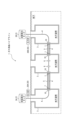
- FIG. 1 is a diagram illustrating an example of a gas supply pipeline 1 according to the present embodiment.
- the gas supply pipeline 1 includes a tank 2A on the supply side, a tank 2B on the consumption side, a pressure gauge 20, an underground space 3, piping 4, an existing pipe 5, a fixture 6, a duct part 7, Equipped with
- the gas supply pipeline 1 is a pipe that carries gas (for example, hydrogen gas) stored in a supply side tank 2A installed above ground through a plurality of underground spaces 3 connected by existing pipes 5. 4 is used as a transport pipe to transport and supply to the tank 2B on the consumption side installed on the ground.
- gas for example, hydrogen gas
- the supply side tank 2A is a tank that stores gas such as hydrogen gas.
- the consumption-side tank 2B is a tank installed at a consumption area that stores the gas transported from the supply-side tank 2A using the pipe 4 as a transport conduit.
- the tank 2A on the supply side and the tank 2B on the consumption side are described as being installed on the ground, they are not limited to installation on the ground.
- the underground space 3 is a hollow space such as a manhole, tunnel structure, handhole, etc.
- the side wall of the underground space 3 is provided with a duct opening 7 (hereinafter also referred to as duct part 7) for drawing in or pulling out the pipe 4, and the side wall near each duct part 7 is provided with a pipe clamping device. 10 is fixed. Note that measures are taken to prevent water such as groundwater from flowing into the underground space 3.
- the pipe 4 is a pipe for transporting gas such as hydrogen gas.
- the pipe 4 is laid from the tank 2A on the supply side to the tank 2B on the consumption side via the inside of a plurality of underground spaces 3 connected by existing pipes 5.
- a flexible pipe or the like is used, which is a pipe made of stainless steel with a wave-like shape, and is lightweight and highly flexible.
- the existing pipe 5 is a pipe installed in advance between the two underground spaces 3. By accommodating the pipe 4 inside the existing pipe 5, a pipe line with a double pipe structure is constructed.
- the fixture 6 is installed in the underground space fixing part to support and fix the pipe 4 in order to prevent the pipe 4 from bending inside the underground space 3.
- the duct portion 7 is a duct opening that penetrates the wall surface of the underground space 3 in order to draw in or pull out the piping 4.
- the pressure gauges 20 (20A, 20B) measure the gas pressure inside the piping 4 in the supply side tank 2A and the consumption side tank 2B.
- the gas pressure inside the piping 4 in the tank 2A on the supply side and the tank 2B on the consumption side is compared, and if the gas pressure inside the piping 4 in the tank 2B on the consumption side is equal to or higher than the threshold value, the piping 4 for pressure-feeding gas is If it is determined that the pipe 4 is constructed normally and the gas pressure inside the pipe 4 in the tank 2B on the consumption side falls below a threshold value, it is determined that buckling, which will be described later, has occurred in the pipe 4 inside the underground space 3. . When it is determined that buckling has occurred in the piping 4, the cause is investigated and the portion where the defect occurs is repaired.
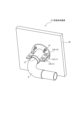
- FIG. 2 is a diagram showing an example of the configuration of the pipe clamping device 10 according to the present embodiment.
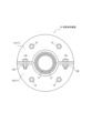
- FIG. 3 is a sectional view of the pipe clamping device 10 according to the present embodiment.
- the pipe clamping device 10 includes a pair of fixing members 11, a covering material 12, one or more bolts/nuts 13, and one or more anchor bolts 14.
- the pipe clamping device 10 suppresses buckling in the underground space 3 of the pipe 4 that pressure-feeds gas.
- one of the pair of fixing members 11 will be denoted as 11A, and the other fixing member will be denoted as 11B.
- the fixed member 11A and the fixed member 11B are also written as the fixed member 11.
- the pair of fixing members 11A and 11B are arranged opposite to each other with the piping 4 in between, and are tightened from both sides by one or more bolts and nuts 13 (bolts 13A and nuts 13B), thereby holding the piping 4 between them. Furthermore, by fixing the pair of fixing members 11A and 11B that sandwich the pipe 4 to the side wall 3A of the underground space near the duct part 7 with one or more anchor bolts 14, the force that causes the pipe 4 to stretch is reduced. It becomes possible to receive the pipe 4 on the surface, and it becomes possible to suppress the extension of the pipe 4 in the underground space 3.
- FIG. 4 is a diagram showing a configuration example of the fixing member 11 according to this embodiment.
- FIG. 5 is a front view, a top view, and a side view of the fixing member according to this embodiment.
- the fixing member 11 (11A, 11B) includes a pipe holding part 111, a tightening part 112, and a fixing part 113.
- the pipe clamping part 111 has a semi-cylindrical shape obtained by cutting a cylindrical body in half, and clamps half of the outer circumference of the pipe 4.
- the pipe holding part 111 has a semi-cylindrical shape (half-split structure) in which the pipe holding device 10 can be installed even if the pipe 4 is already installed in the duct part 7 of the underground space 3. ).
- the tightening part 112 is molded into a flat plate shape by integral molding with the pipe holding part 111.
- the tightening parts 112 are formed at both ends of the pipe holding part 111 in the first direction (denoted as the X-axis direction in FIG. 4), and each has one or more bolt holes 112h.
- the fixing part 113 has a flat plate shape, and is arranged in a second direction (denoted as the Y-axis direction in FIG. 4) perpendicular to the first direction (X-axis direction) of the pipe holding part 111 and the tightening part 112. , joined at one end. Further, the fixing portion 113 is arranged in a third direction (denoted as the Z-axis direction in FIG. 4) orthogonal to the first direction and the second direction. Furthermore, the fixing portion 113 has one or more anchor bolt holes 113h.
- the fixing part 113 may be joined to the pipe clamping part 111 and the tightening part 112 by welding, but the joining method is not limited to welding.
- the fixing part 113 may be integrally molded with the pipe holding part 111 and the tightening part 112 by press working or the like.
- the fixing part 113 is expressed as a semicircular flat plate, but the shape of the fixing part 113 is not limited to the semicircular shape.
- the shape of the fixing portion 113 may be a polygon such as a rectangle.
- the pair of fixing members 11A and 11B be made of the same material as the pipe 4.
- manufacturing the pair of fixing members 11A, 11B and the pipe 4 from the same material is beneficial in suppressing the occurrence of contact corrosion due to dissimilar metals. For this reason, it is desirable that the pair of fixing members 11A and 11B be made of the same material as the flexible tube 4 (such as SUS).
- the covering material 12 is installed between the pair of fixing members 11A, 11B and the pipe 4, and covers the outer periphery of the pipe 4.
- the covering material 12 suppresses the occurrence of rust due to contact corrosion between different metals between the material of the pair of fixing members 11A, 11B and the material of the piping 4, and also protects the piping when sandwiched between the pair of fixing members 11A, 11B.
- a cushioning material such as rubber.
- the bolt/nut 13 is attached to one or more bolt holes 112h formed in the tightening portion 112 formed at both ends of the pair of fixing members 11A and 11B, and tightens the fixing member 11A and the fixing member 11B. .
- the pair of fixing members 11A and 11B sandwich the pipe 4 whose outer periphery is covered with the covering material 12. .
- the anchor bolt 14 is attached to one or more anchor bolt holes 113h formed in each of the fixing parts 113 of the pair of fixing members 11A and 11B.
- a pair of fixing members 11A and 11B that sandwich the pipe 4 are fixed to the side wall 3A of the underground space with anchor bolts 14.
- holes for attaching the anchor bolts 14 are previously installed in the side wall 3A of the underground space. Since the holes drilled in the side wall 3A of the underground space do not reach the back surface (soil) of the underground space 3, no inflow of groundwater occurs.
- the pipe clamping device 10 is installed so as not to interfere with the duct sleeve installed in the duct portion 7.
- the duct sleeve is a member that forms the entrance surface of the underground space 3 (manhole, etc.).
- FIG. 6 is a diagram showing the state of the piping before and after the gas is pumped. As shown in FIG. 6, by fixing the pipe clamping device 10 near the duct portion 7 after gas pressure feeding, the area a between the duct portion 7 and the underground space fixing portion where the fixing device 6 is installed. In this case, buckling of the pipe 4 can be suppressed.
- FIG. 7 is a flowchart showing an example of a pipe clamping method for suppressing buckling of the pipe 4 according to the present embodiment.
- step S101 a worker accommodates the gas transport pipe 4 within the existing pipe 5.
- step S102 a worker joins the pipes 4 together.
- the piping 4 has a length limit due to standards. Therefore, in order to secure the distance from the tank 2A on the supply side to the tank 2B on the consumption side via a plurality of underground spaces 3, a plurality of pipes 4 are joined as necessary.
- step S103 the worker covers the outer periphery of the pipe 4 at the portion held between the pair of fixing members 11 with the covering material 12.
- step S104 the worker holds the pipe 4 between the pair of fixing members 11.
- step S105 the worker fixes the pair of fixing members holding the pipe 4 to the side wall 3A of the underground space with the anchor bolt 14.
- step S106 the worker pressure-feeds gas to the pipe 4.
- step S107 the worker compares the measured values of the gas pressure in the supply side tank 2A and the demand side tank 2B using the pressure gauge 20, and determines the gas pressure inside the pipe 4 in the consumption side tank 2B. Measure whether or not it is above a threshold value. If the gas pressure inside the pipe 4 in the consumption side tank 2B is less than the threshold value, the process proceeds to step S108, and if it is equal to or higher than the threshold value, the pipe clamping work is ended.
- step S108 the worker determines that buckling has occurred in the pipe 4 based on the fact that the gas pressure inside the pipe 4 in the consumption side tank 2B has fallen below the threshold value.
- step S109 the worker investigates whether the anchor bolt 14 has come off, the pipe clamping device 10 has been damaged, etc., and determines the cause of the buckling. Once the cause of the buckling has been determined, the process returns to step S101 and the pipe clamping operation is performed again.
- the pipe clamping device 10 it is possible to prevent the occurrence of buckling by suppressing the elongation of the pipe after the gas is pumped. Moreover, by preventing the occurrence of buckling, it is possible to prevent holes from forming in the pipe 4 and reduce the risk of an explosion accident due to leakage of gas such as hydrogen gas. Moreover, according to the pipe clamping device 10, it is possible to reduce the number of times that repairs and the like need to be carried out, and it is also possible to increase economic effects.
- a pipe clamping device for suppressing buckling of a pipe for pumping gas in an underground space comprising a pair of fixing members arranged opposite to each other, each of which is fixed to a side wall of the underground space and clamps the pipe;
- a pipe clamping device comprising: a covering material installed between a pair of fixing members and the pipe to cover the outer periphery of the pipe.
- the pair of fixing members are integrally molded with a semi-cylindrical pipe holding part, which is a halved cylindrical body, which holds a half circumference of the outer periphery of the pipe, and the pipe holding part.
- a pipe clamping method for suppressing buckling of a pipe for pumping gas in an underground space comprising: covering the outer periphery of the pipe with a covering material, and clamping the covered pipe from both sides by a pair of fixing members.
- a pipe clamping method that determines that buckling of the pipe has occurred when the pressure of the gas falls below a threshold value.
Landscapes
- Engineering & Computer Science (AREA)
- General Engineering & Computer Science (AREA)
- Mechanical Engineering (AREA)
- Protection Of Pipes Against Damage, Friction, And Corrosion (AREA)
- Supports For Pipes And Cables (AREA)
Abstract
配管挟持器具(10)は、それぞれが地下空間の側壁に固定され、配管を挟持する、対向配置された一対の固定部材(11)と、一対の固定部材(11)と配管との間に装着されて、配管の外周を被覆する被覆材(12)と、を備える。
Description
本開示は、配管挟持器具及び配管挟持方法に関する。
近年、脱炭素化を目指し、カーボンニュートラルの実現に向けて、水素ガスを活用するために、水素ガスを供給する方法、及び水素ガスの供給における安全性が検討されている(非特許文献1参照)。
従来、水素ガスを供給するための水素パイプラインは、掘削した地中に直接埋設されていた。このため、水素ガスの圧送時に、土壌の拘束力により、水素パイプ(水素配管)に伸縮が発生することはなかった。
図8は、複数の地下空間を経由して敷設される水素パイプラインの一例を説明する図である。従来、水素パイプラインは、上述した地中に直接埋設されるものに加え、図8に示すように複数の地下空間を経由して敷設されるものが導入されている。水素パイプは、複数の地下空間を連結する既設管の内部の空き管路に敷設されており、複数の水素パイプが接合された水素パイプラインが構築されている。かかる水素パイプラインにおいて、水素ガスは、供給側の水素タンクから需要側の水素タンクへと輸送・供給される。さらに、既設管の管路の不陸(面が水平でなく、凹凸があることを言う。)、既設管内部あるいは地下空間内における曲線施工等に対応するため、水素パイプには軽量かつ柔軟性に富んだフレキシブル管が採択される。フレキシブル管は、ステンレス鋼の波状形状の原管等で構成されており、軽量かつ柔軟性に富む配管である。地下空間内には、フレキシブルに伸縮するフレキシブル管がたわむのを防ぐため、地下空間内に固定具が設置される。
森田哲司、「都市ガス業界における水素パイプライン供給に関する取組み」、一般社団法人 電気設備学会、電気設備学会誌、36巻4号、P.242-245、2016年
しかし、土壌等の拘束力のない地下空間内において、フレキシブル管に水素ガスが圧送されると、水素ガスの圧力によりフレキシブル管が伸びることにより、座屈が発生することがある。フレキシブル管の座屈は、最悪の場合には、配管(パイプ)に穴が開くことに起因する爆発事故につながるおそれがある。図9は、水素ガス圧送後における配管の座屈の発生を示す図である。フレキシブル管の座屈は、水素ガスの圧送時の圧力により、地下空間内のフレキシブル管が伸びてしまうことにより発生する。また、フレキシブル管の座屈は、ダクト部と、固定具が設置された地下空間固定部との間において発生する。座屈とは、構造物に加える荷重を増加させると、ある荷重で急に変形の模様が変化し、大きなたわみが生ずることをいう。このため、土壌等の拘束力のない地下空間内では、フレキシブル管の伸びによる座屈の発生を抑制することが課題となる。
かかる事情に鑑みてなされた本発明の目的は、ガスの圧送時におけるフレキシブル管の地下空間内における座屈を抑制することにある。
上記課題を解決するため、本実施形態に係る配管挟持器具は、ガスを圧送する配管の地下空間内での座屈を抑制する配管挟持器具であって、それぞれが地下空間の側壁に固定され、前記配管を挟持する、対向配置された一対の固定部材と、前記一対の固定部材と前記配管との間に装着されて、前記配管の外周を被覆する被覆材と、を備える。
上記課題を解決するため、本実施形態に係る配管挟持方法は、ガスを圧送する配管の地下空間内での座屈を抑制する配管挟持方法であって、前記配管の外周を被覆材により被覆するステップと、被覆された前記配管を一対の固定部材により、両側から挟持するステップと、前記一対の固定部材のそれぞれを地下空間の側壁に固定させるステップと、圧力計により計測された、消費側のタンクにおける前記配管の内部の前記ガスの圧力が閾値以上であるか否かを判定するステップと、前記ガスの圧力が閾値を下回ると、前記配管の座屈が発生したと判断するステップと、を実行する。
本開示によれば、ガスの圧送後に配管の伸びを抑制することにより、座屈の発生を防止することが可能になる。
以下、本発明を実施するための形態が、図面を参照しながら詳細に説明される。本発明は、以下の実施形態に限定されるものではなく、その要旨の範囲内で種々変形して実施することができる。以下、本実施形態では、圧送するガスとして水素ガスを一例として説明を行うが、圧送するガスは、水素ガスに限定されるものではない。
<ガス供給パイプライン>
図1は、本実施形態に係るガス供給パイプライン1の一例を説明する図である。ガス供給パイプライン1は、供給側のタンク2Aと、消費側のタンク2Bと、圧力計20と、地下空間3と、配管4と、既設管5と、固定具6と、ダクト部7と、を備える。ガス供給パイプライン1は、地上に設置された供給側のタンク2Aに貯蔵されたガス(例えば、水素ガス)を、既設管5で連結された複数の地下空間3を経由して敷設された配管4を輸送管路として、地上に設置された消費側のタンク2Bに輸送・供給する。
図1は、本実施形態に係るガス供給パイプライン1の一例を説明する図である。ガス供給パイプライン1は、供給側のタンク2Aと、消費側のタンク2Bと、圧力計20と、地下空間3と、配管4と、既設管5と、固定具6と、ダクト部7と、を備える。ガス供給パイプライン1は、地上に設置された供給側のタンク2Aに貯蔵されたガス(例えば、水素ガス)を、既設管5で連結された複数の地下空間3を経由して敷設された配管4を輸送管路として、地上に設置された消費側のタンク2Bに輸送・供給する。
供給側のタンク2Aは、水素ガス等のガスを貯蔵するタンクである。消費側のタンク2Bは、配管4を輸送管路として、供給側のタンク2Aから輸送されたガスを貯蔵する、消費地に設置されたタンクである。なお、本実施形態において、供給側のタンク2A及び消費側のタンク2Bは、地上に設置されているものとして説明するが、地上設置に限定されるものではない。
地下空間3は、マンホール、トンネル構造物、ハンドホール等の内部が空洞の空間である。地下空間3の側壁には、配管4を引き込み又は引き出すためのダクト口7(以下、ダクト部7ともいう。)が設けられており、それぞれのダクト部7の近傍の側壁には、配管挟持器具10が固定される。なお、地下空間3には、地下水等の水が流入しないための対策が講じられている。
配管4は、水素ガス等のガスを輸送するための管路である。配管4は、供給側のタンク2Aから消費側のタンク2Bまでの間を、既設管5で連結された複数の地下空間3の内部を経由して敷設される。配管4には、ステンレス鋼の波状形状の原管等で構成されており、軽量かつ柔軟性に富む配管であるフレキシブル管等が用いられる。
既設管5は、2つの地下空間3の間に予め設置されている管路である。既設管5の内部に配管4を収容することにより2重配管構造の管路が構築される。
固定具6は、地下空間3の内部において、配管4がたわむのを防ぐために、配管4を支持固定するために、地下空間固定部に、設置される。
ダクト部7は、配管4を引き込み又は引き出すために、地下空間3の壁面を貫通するダクト口である。
圧力計20(20A,20B)は、供給側のタンク2A及び消費側のタンク2Bにおける配管4の内部のガス圧力を計測する。供給側のタンク2A及び消費側のタンク2Bにおける配管4の内部のガス圧力を比較し、消費側のタンク2Bにおける配管4の内部のガス圧力が閾値以上であると、ガスを圧送する配管4は正常に構築されていると判定され、消費側のタンク2Bにおける配管4の内部のガス圧力が閾値を下回ると、地下空間3の内部における配管4に、後述する座屈が発生したと判断される。配管4に座屈が発生したと判断されると、原因の究明が行われ、不具合が発生した部位の補修が行われる。
<配管挟持器具>
図2は、本実施形態に係る配管挟持器具10の構成例を示す図である。また、図3は、本実施形態に係る配管挟持器具10の断面図である。図2及び図3に示すように、配管挟持器具10は、一対の固定部材11と、被覆材12と、1以上のボルト・ナット13と、1以上のアンカーボルト14と、を備える。配管挟持器具10は、ガスを圧送する配管4の地下空間3内での座屈を抑制する。以下、一対の固定部材11の一方の固定部材は11Aと、他方の固定部材は11Bと表記される。なお、固定部材11A及び固定部材11Bを区別しない場合には、固定部材11A及び固定部材11Bは、固定部材11とも表記される。
図2は、本実施形態に係る配管挟持器具10の構成例を示す図である。また、図3は、本実施形態に係る配管挟持器具10の断面図である。図2及び図3に示すように、配管挟持器具10は、一対の固定部材11と、被覆材12と、1以上のボルト・ナット13と、1以上のアンカーボルト14と、を備える。配管挟持器具10は、ガスを圧送する配管4の地下空間3内での座屈を抑制する。以下、一対の固定部材11の一方の固定部材は11Aと、他方の固定部材は11Bと表記される。なお、固定部材11A及び固定部材11Bを区別しない場合には、固定部材11A及び固定部材11Bは、固定部材11とも表記される。
一対の固定部材11A,11Bは、それぞれが、配管4を挟んで対向配置され、1以上のボルト・ナット13(ボルト13A及びナット13B)により両側から締め付けられることにより、配管4を挟持する。さらに、配管4を挟持する一対の固定部材11A,11Bを、1以上のアンカーボルト14により、ダクト部7の近傍の地下空間の側壁3Aに固定することにより、配管4が伸びようとする力を面で受け止めることが可能となり、配管4の地下空間3内での伸びを抑制することが可能となる。
<固定部材>
図4は、本実施形態に係る固定部材11の構成例を示す図である。また、図5は、本実施形態に係る固定部材の正面図、平面図及び側面図である。図4及び図5に示すように、固定部材11(11A,11B)は、配管挟持部111と、締付部112と、固定部113と、を備える。
図4は、本実施形態に係る固定部材11の構成例を示す図である。また、図5は、本実施形態に係る固定部材の正面図、平面図及び側面図である。図4及び図5に示すように、固定部材11(11A,11B)は、配管挟持部111と、締付部112と、固定部113と、を備える。
配管挟持部111は、円筒体を半割にした半円筒形状を有し、配管4の外周の半周を挟持する。配管挟持部111は、配管4が地下空間3のダクト部7に既設の状態であっても、配管挟持器具10を設置可能とするため、円筒体を半割にした半円筒形状(半割構造)とした。
締付部112は、配管挟持部111との一体成型により、平板形状に成型される。締付部112は、配管挟持部111の第1の方向(図4においてX軸方向と表記。)の両端に形成されており、それぞれが1以上のボルト孔112hを有する。
固定部113は、平板形状を有し、配管挟持部111と締付部112の、第1の方向(X軸方向)と直交する第2の方向(図4においてY軸方向と表記。)における、一方の端部に接合されている。また、固定部113は、第1の方向及び第2の方向と直交する第3の方向(図4においてZ軸方向と表記。)に配置されている。また、固定部113は、1以上のアンカーボルト孔113hを有する。固定部113は、配管挟持部111及び締付部112と溶接により接合されてもよいが、接合方法は溶接に限定されるものではない。固定部113は、配管挟持部111及び締付部112とプレス加工等により一体成型されてもよい。図4及び図5において、固定部113は、半円形の平板形状に表現されているが、固定部113の形状は、半円形に限定されるものではない。固定部113の形状は、長方形等の多角形であってもよい。
一対の固定部材11A,11Bは、配管4の材質と同一の材質で製作されることが望ましい。ガス圧送時の配管4(フレキシブル管4)の伸びを抑制するためには、配管4及び一対の固定部材11A,11Bの熱膨張係数を合わせることが有益である。また、一対の固定部材11A,11Bと配管4とを同一の材質で製作することは、異種金属による接触腐食の発生を抑制することに有益である。このため、一対の固定部材11A,11Bの材質は、フレキシブル管4と同じ材質(SUS等)とすることが望ましい。
被覆材12は、一対の固定部材11A,11Bと配管4との間に装着されて、配管4の外周を被覆する。被覆材12は、一対の固定部材11A,11Bの材料と、配管4の材料との間の異種金属接触腐食による発錆の発生を抑制し、かつ一対の固定部材11A,11Bで挟み込む際に配管4に傷が付くことを抑制するため、ゴム等の緩衝材とすることが望ましい。
ボルト・ナット13は、一対の固定部材11A,11Bのそれぞれの両端に形成された締付部112に開孔された1以上のボルト孔112hに取り付けられ、固定部材11Aと固定部材11Bとを締め付ける。それぞれの締付部112が1以上のボルト・ナット13(ボルト13A及びナット13B)で締め付けられることにより、一対の固定部材11A,11Bは、被覆材12で外周を被覆された配管4を挟持する。
アンカーボルト14は、一対の固定部材11A,11Bのそれぞれの固定部113に開孔された1以上のアンカーボルト孔113hに取り付けられる。配管4を挟持する一対の固定部材11A,11Bは、地下空間の側壁3Aにアンカーボルト14により固定させる。配管挟持器具10を1以上のアンカーボルト14で固定することによって配管4の伸びに抵抗するため、地下空間の側壁3Aには、予めアンカーボルト14を取り付ける孔が設置されている。地下空間の側壁3Aに開孔された孔は、地下空間3の背面(土壌)には達しないため、地下水の流入は発生しない。なお、配管挟持器具10は、ダクト部7に設置されているダクトスリーブには干渉しないように設置される。ダクトスリーブとは、地下空間3(マンホール等)の入口面を形成する部材である。
以上の様に、地下空間3内にガスを圧送する配管4を設置する際には、(i)配管挟持器具10は、一対の固定部材11A,11Bの半割構造の配管挟持部111で配管4の外周を挟持し、(ii)次に配管挟持器具10は、平面形状の固定部113で地下空間の側壁3Aに固定される。この様にして、配管挟持器具10は、突き出し(伸び)防止機能を果たすことが可能となる。図6は、ガス圧送前及び圧送後における配管の状態を示す図である。図6に示すように、ガス圧送後において、配管挟持器具10をダクト部7の近傍に固定することにより、ダクト部7と、固定具6が設置された地下空間固定部との間の領域aにおいて、配管4の座屈を抑制することが可能となる。
<配管挟持方法>
図7は、本実施形態に係る配管4の座屈を抑制する配管挟持方法の一例を示すフローチャートである。
図7は、本実施形態に係る配管4の座屈を抑制する配管挟持方法の一例を示すフローチャートである。
ステップS101では、作業員が、既設管5の管内に、ガス輸送用の配管4を収容する。
ステップS102では、作業員が、配管4同士を接合する。配管4は、規格上長さの限界がある。このため、供給側のタンク2Aから、複数の地下空間3を経由して、消費側のタンク2Bに至る距離を確保するため、必要に応じて複数の配管4が接合される。
ステップS103では、作業員が、一対の固定部材11で挟持される部分の配管4の外周を被覆材12で被覆する。
ステップS104では、作業員が、一対の固定部材11で配管4を挟持する。
ステップS105では、作業員が、配管4を挟持した一対の固定部材を地下空間の側壁3Aにアンカーボルト14で固定する。
ステップS106では、作業員が、配管4にガスを圧送する。
ステップS107では、作業員が、圧力計20により、供給側のタンク2A及び需要側のタンク2Bのガス圧力を計測した計測値を比較し、消費側のタンク2Bにおける配管4の内部のガス圧力が閾値以上であるか否かを計測する。消費側のタンク2Bにおける配管4の内部のガス圧力が閾値を下回ると、ステップS108へ進み、閾値以上であると、配管の挟持作業を終了する。
ステップS108では、作業員が、消費側のタンク2Bにおける配管4の内部のガス圧力が閾値を下回ったことに基づき、配管4に座屈が発生したと判断する。
ステップS109では、作業員が、アンカーボルト14の抜け、配管挟持器具10の破損等を調査して、座屈の発生原因を究明する。座屈の発生原因が究明されると、ステップS101へ戻り、配管の挟持作業を再度実行する。
本開示に係る配管挟持器具10によれば、ガスの圧送後の配管の伸びを抑制することにより、座屈の発生を防止することが可能になる。また、座屈発生を防止することにより、配管4に穴が開くことを未然に防ぎ、水素ガスなどのガスの漏洩による爆発事故等の発生リスクを低減することが可能となる。また、配管挟持器具10によれば、補修等の実施の必要回数を低減することが可能となり、経済的効果を高めることも可能となる。
以上の実施形態に関し、更に以下の付記を開示する。
(付記項1)
ガスを圧送する配管の地下空間内での座屈を抑制する配管挟持器具であって、それぞれが地下空間の側壁に固定され、前記配管を挟持する、対向配置された一対の固定部材と、前記一対の固定部材と前記配管との間に装着されて、前記配管の外周を被覆する被覆材と、を備える配管挟持器具。
(付記項2)
前記一対の固定部材は、前記配管の外周の半周を挟持する、円筒体を半割にした半円筒形状の配管挟持部と、前記配管挟持部との一体成型により、前記配管挟持部の第1の方向の両端に形成された、それぞれが1以上のボルト孔を有する平板形状の締付部と、前記配管挟持部と前記締付部の、前記第1の方向と直交する第2の方向における、一方の端部に接合された、1以上のボルト孔を有する平板形状の固定部と、をそれぞれ備える、付記項1に記載の配管挟持器具。
(付記項3)
前記一対の固定部材は、それぞれの前記締付部を、1以上のボルト・ナットで締付けることにより、前記被覆材で外周を被覆された前記配管を挟持する、付記項1又は2に記載の配管挟持器具。
(付記項4)
前記一対の固定部材は、それぞれが前記地下空間の側壁にアンカーボルトにより固定される、付記項1から3のいずれか一項に記載の配管挟持器具。
(付記項5)
前記一対の固定部材は、前記配管の材質と同一の材質で製作される、付記項1から4のいずれか一項に記載の配管挟持器具。
(付記項6)
前記被覆材の材質は、ゴムである、付記項1から5のいずれか一項に記載の配管挟持器具。
(付記項7)
ガスを圧送する配管の地下空間内での座屈を抑制する配管挟持方法であって、前記配管の外周を被覆材により被覆し、被覆された前記配管を一対の固定部材により、両側から挟持し、前記一対の固定部材のそれぞれを地下空間の側壁に固定させ、圧力計により計測された、消費側のタンクにおける前記配管の内部の前記ガスの圧力が閾値以上であるか否かを判定し、前記ガスの圧力が閾値を下回ると、配管の座屈が発生したと判断する配管挟持方法。
ガスを圧送する配管の地下空間内での座屈を抑制する配管挟持器具であって、それぞれが地下空間の側壁に固定され、前記配管を挟持する、対向配置された一対の固定部材と、前記一対の固定部材と前記配管との間に装着されて、前記配管の外周を被覆する被覆材と、を備える配管挟持器具。
(付記項2)
前記一対の固定部材は、前記配管の外周の半周を挟持する、円筒体を半割にした半円筒形状の配管挟持部と、前記配管挟持部との一体成型により、前記配管挟持部の第1の方向の両端に形成された、それぞれが1以上のボルト孔を有する平板形状の締付部と、前記配管挟持部と前記締付部の、前記第1の方向と直交する第2の方向における、一方の端部に接合された、1以上のボルト孔を有する平板形状の固定部と、をそれぞれ備える、付記項1に記載の配管挟持器具。
(付記項3)
前記一対の固定部材は、それぞれの前記締付部を、1以上のボルト・ナットで締付けることにより、前記被覆材で外周を被覆された前記配管を挟持する、付記項1又は2に記載の配管挟持器具。
(付記項4)
前記一対の固定部材は、それぞれが前記地下空間の側壁にアンカーボルトにより固定される、付記項1から3のいずれか一項に記載の配管挟持器具。
(付記項5)
前記一対の固定部材は、前記配管の材質と同一の材質で製作される、付記項1から4のいずれか一項に記載の配管挟持器具。
(付記項6)
前記被覆材の材質は、ゴムである、付記項1から5のいずれか一項に記載の配管挟持器具。
(付記項7)
ガスを圧送する配管の地下空間内での座屈を抑制する配管挟持方法であって、前記配管の外周を被覆材により被覆し、被覆された前記配管を一対の固定部材により、両側から挟持し、前記一対の固定部材のそれぞれを地下空間の側壁に固定させ、圧力計により計測された、消費側のタンクにおける前記配管の内部の前記ガスの圧力が閾値以上であるか否かを判定し、前記ガスの圧力が閾値を下回ると、配管の座屈が発生したと判断する配管挟持方法。
上述の実施形態は代表的な例として説明したが、本開示の趣旨及び範囲内で、多くの変更及び置換ができることは当業者に明らかである。したがって、本発明は、上述の実施形態によって制限するものと解するべきではなく、特許請求の範囲から逸脱することなく、種々の変形又は変更が可能である。
1 ガス供給パイプライン
2A 供給側のタンク
2B 消費側のタンク
3 地下空間
3A 地下空間の側壁
4 配管(フレキシブル管)
5 既設管
6 固定具
7 ダクト部(ダクト口)
10 配管挟持器具
11,11A,11B 固定部材
12 被覆材
13 ボルト・ナット
13A ボルト
13B ナット
14 アンカーボルト
20,20A,20B 圧力計
111 配管挟持部
112 締付部
112h ボルト孔
113 固定部
113h アンカーボルト孔
2A 供給側のタンク
2B 消費側のタンク
3 地下空間
3A 地下空間の側壁
4 配管(フレキシブル管)
5 既設管
6 固定具
7 ダクト部(ダクト口)
10 配管挟持器具
11,11A,11B 固定部材
12 被覆材
13 ボルト・ナット
13A ボルト
13B ナット
14 アンカーボルト
20,20A,20B 圧力計
111 配管挟持部
112 締付部
112h ボルト孔
113 固定部
113h アンカーボルト孔
Claims (7)
- ガスを圧送する配管の地下空間内での座屈を抑制する配管挟持器具であって、
それぞれが地下空間の側壁に固定され、前記配管を挟持する、対向配置された一対の固定部材と、
前記一対の固定部材と前記配管との間に装着されて、前記配管の外周を被覆する被覆材と、
を備える配管挟持器具。 - 前記一対の固定部材は、
前記配管の外周の半周を挟持する、円筒体を半割にした半円筒形状の配管挟持部と、
前記配管挟持部との一体成型により、前記配管挟持部の第1の方向の両端に形成された、それぞれが1以上のボルト孔を有する平板形状の締付部と、
前記配管挟持部と前記締付部の、前記第1の方向と直交する第2の方向における、一方の端部に接合された、1以上のボルト孔を有する平板形状の固定部と、
をそれぞれ備える、請求項1に記載の配管挟持器具。 - 前記一対の固定部材は、それぞれの前記締付部を、1以上のボルト・ナットで締付けることにより、前記被覆材で外周を被覆された前記配管を挟持する、請求項1又は2に記載の配管挟持器具。
- 前記一対の固定部材は、それぞれが前記地下空間の側壁にアンカーボルトにより固定される、請求項1又は2に記載の配管挟持器具。
- 前記一対の固定部材は、前記配管の材質と同一の材質で製作される、請求項1又は2に記載の配管挟持器具。
- 前記被覆材の材質は、ゴムである、請求項1又は2に記載の配管挟持器具。
- ガスを圧送する配管の地下空間内での座屈を抑制する配管挟持方法であって、
前記配管の外周を被覆材により被覆するステップと、
被覆された前記配管を一対の固定部材により、両側から挟持するステップと、
前記一対の固定部材のそれぞれを地下空間の側壁に固定させるステップと、
圧力計により計測された、消費側のタンクにおける前記配管の内部の前記ガスの圧力が閾値以上であるか否かを判定するステップと、
前記ガスの圧力が閾値を下回ると、前記配管の座屈が発生したと判断するステップと、
を実行する配管挟持方法。
Priority Applications (3)
| Application Number | Priority Date | Filing Date | Title |
|---|---|---|---|
| PCT/JP2022/029850 WO2024029009A1 (ja) | 2022-08-03 | 2022-08-03 | 配管挟持器具及び配管挟持方法 |
| JP2024538593A JPWO2024029009A1 (ja) | 2022-08-03 | 2022-08-03 | |
| US19/100,201 US20260043496A1 (en) | 2022-08-03 | 2022-08-03 | Pipe clamping appliance and pipe clamping method |
Applications Claiming Priority (1)
| Application Number | Priority Date | Filing Date | Title |
|---|---|---|---|
| PCT/JP2022/029850 WO2024029009A1 (ja) | 2022-08-03 | 2022-08-03 | 配管挟持器具及び配管挟持方法 |
Publications (1)
| Publication Number | Publication Date |
|---|---|
| WO2024029009A1 true WO2024029009A1 (ja) | 2024-02-08 |
Family
ID=89848698
Family Applications (1)
| Application Number | Title | Priority Date | Filing Date |
|---|---|---|---|
| PCT/JP2022/029850 Ceased WO2024029009A1 (ja) | 2022-08-03 | 2022-08-03 | 配管挟持器具及び配管挟持方法 |
Country Status (3)
| Country | Link |
|---|---|
| US (1) | US20260043496A1 (ja) |
| JP (1) | JPWO2024029009A1 (ja) |
| WO (1) | WO2024029009A1 (ja) |
Citations (4)
| Publication number | Priority date | Publication date | Assignee | Title |
|---|---|---|---|---|
| JPS5858175U (ja) * | 1982-08-18 | 1983-04-20 | 株式会社ハツコ− | 地下構造物の管体貫通部の防水構造 |
| JPH07217785A (ja) * | 1994-02-01 | 1995-08-15 | Tokyo Gas Co Ltd | ガス導管の分岐接続部におけるシール装置 |
| JPH10205682A (ja) * | 1997-01-24 | 1998-08-04 | Nkk Corp | 既設管の管継手構造およびその施工方法 |
| CN212056166U (zh) * | 2020-04-01 | 2020-12-01 | 中建八局第二建设有限公司 | 一种地下室外墙出墙管道的连接装置 |
Family Cites Families (4)
| Publication number | Priority date | Publication date | Assignee | Title |
|---|---|---|---|---|
| JP3387592B2 (ja) * | 1993-12-21 | 2003-03-17 | 株式会社オーケーエム | 流体漏洩検知システム |
| JPH10292900A (ja) * | 1997-04-16 | 1998-11-04 | Matsushita Electric Ind Co Ltd | 流量計測装置及び配管容量計測方法 |
| JPH11132820A (ja) * | 1997-10-31 | 1999-05-21 | Yazaki Corp | ガスメータ |
| DE102014013419A1 (de) * | 2014-09-10 | 2016-03-10 | Fresenius Medical Care Deutschland Gmbh | Vorrichtung umfassend einen mehrlumigen Schlauch |
-
2022
- 2022-08-03 JP JP2024538593A patent/JPWO2024029009A1/ja active Pending
- 2022-08-03 US US19/100,201 patent/US20260043496A1/en active Pending
- 2022-08-03 WO PCT/JP2022/029850 patent/WO2024029009A1/ja not_active Ceased
Patent Citations (4)
| Publication number | Priority date | Publication date | Assignee | Title |
|---|---|---|---|---|
| JPS5858175U (ja) * | 1982-08-18 | 1983-04-20 | 株式会社ハツコ− | 地下構造物の管体貫通部の防水構造 |
| JPH07217785A (ja) * | 1994-02-01 | 1995-08-15 | Tokyo Gas Co Ltd | ガス導管の分岐接続部におけるシール装置 |
| JPH10205682A (ja) * | 1997-01-24 | 1998-08-04 | Nkk Corp | 既設管の管継手構造およびその施工方法 |
| CN212056166U (zh) * | 2020-04-01 | 2020-12-01 | 中建八局第二建设有限公司 | 一种地下室外墙出墙管道的连接装置 |
Also Published As
| Publication number | Publication date |
|---|---|
| US20260043496A1 (en) | 2026-02-12 |
| JPWO2024029009A1 (ja) | 2024-02-08 |
Similar Documents
| Publication | Publication Date | Title |
|---|---|---|
| US7540539B2 (en) | Pipe joint | |
| KR100820860B1 (ko) | 플랜지 형태의 수밀용 파형강관 연결장치 | |
| US20150337995A1 (en) | Mechanically lined pipe | |
| KR102779061B1 (ko) | 배관의 내진용 흔들림 방지 버팀대 | |
| JP5067585B2 (ja) | 断層用管路 | |
| JP4363565B2 (ja) | バルブピット用フランジ接合体 | |
| KR20140049653A (ko) | 배관 연결장치 | |
| WO2024029009A1 (ja) | 配管挟持器具及び配管挟持方法 | |
| Kim et al. | Limit state assessment for bending deformation of multi-ply bellows systems | |
| US11199277B2 (en) | Non-welded type branch piping reinforcement apparatus | |
| KR101844820B1 (ko) | 내압성능이 향상된 신축 관 이음장치 | |
| US9636787B2 (en) | Non-welding apparatus for repair of an enclosure wall and methods for use thereof | |
| KR102091182B1 (ko) | 파이프 고정 장치 및 파이프 고정용 클램프 장치 | |
| CN118836318A (zh) | 耐磨翻边接头装置 | |
| JP2009121036A (ja) | 導水ジョイント | |
| JP7336496B2 (ja) | 水密テスト機および検査方法 | |
| KR102638445B1 (ko) | 중고압용 노후배관 보수 방법 및 장치 | |
| CN223137243U (zh) | 复合管管口对接用耐磨翻边接头装置 | |
| CN111396688A (zh) | 一种罐体相贯线封堵装置 | |
| KR102127334B1 (ko) | 가스 배관 구조 | |
| WO2020144926A1 (ja) | 配管接続方法およびフランジ接続体 | |
| JP2024154270A (ja) | 検査装置 | |
| JP2024154271A (ja) | 検査装置 | |
| JP5117775B2 (ja) | 管継手取付方法、および分岐管用管継手構造 | |
| JP7792692B2 (ja) | 可撓止水部材の取付構造 |
Legal Events
| Date | Code | Title | Description |
|---|---|---|---|
| 121 | Ep: the epo has been informed by wipo that ep was designated in this application |
Ref document number: 22953998 Country of ref document: EP Kind code of ref document: A1 |
|
| WWE | Wipo information: entry into national phase |
Ref document number: 2024538593 Country of ref document: JP |
|
| NENP | Non-entry into the national phase |
Ref country code: DE |
|
| 122 | Ep: pct application non-entry in european phase |
Ref document number: 22953998 Country of ref document: EP Kind code of ref document: A1 |