WO2024028950A1 - 軸受の給脂構造 - Google Patents
軸受の給脂構造 Download PDFInfo
- Publication number
- WO2024028950A1 WO2024028950A1 PCT/JP2022/029521 JP2022029521W WO2024028950A1 WO 2024028950 A1 WO2024028950 A1 WO 2024028950A1 JP 2022029521 W JP2022029521 W JP 2022029521W WO 2024028950 A1 WO2024028950 A1 WO 2024028950A1
- Authority
- WO
- WIPO (PCT)
- Prior art keywords
- bearing
- rotating body
- greasing
- sealed space
- housing
- Prior art date
- Legal status (The legal status is an assumption and is not a legal conclusion. Google has not performed a legal analysis and makes no representation as to the accuracy of the status listed.)
- Ceased
Links
Images


Classifications
-
- F—MECHANICAL ENGINEERING; LIGHTING; HEATING; WEAPONS; BLASTING
- F16—ENGINEERING ELEMENTS AND UNITS; GENERAL MEASURES FOR PRODUCING AND MAINTAINING EFFECTIVE FUNCTIONING OF MACHINES OR INSTALLATIONS; THERMAL INSULATION IN GENERAL
- F16C—SHAFTS; FLEXIBLE SHAFTS; ELEMENTS OR CRANKSHAFT MECHANISMS; ROTARY BODIES OTHER THAN GEARING ELEMENTS; BEARINGS
- F16C19/00—Bearings with rolling contact, for exclusively rotary movement
- F16C19/54—Systems consisting of a plurality of bearings with rolling friction
- F16C19/541—Systems consisting of juxtaposed rolling bearings including at least one angular contact bearing
-
- F—MECHANICAL ENGINEERING; LIGHTING; HEATING; WEAPONS; BLASTING
- F16—ENGINEERING ELEMENTS AND UNITS; GENERAL MEASURES FOR PRODUCING AND MAINTAINING EFFECTIVE FUNCTIONING OF MACHINES OR INSTALLATIONS; THERMAL INSULATION IN GENERAL
- F16C—SHAFTS; FLEXIBLE SHAFTS; ELEMENTS OR CRANKSHAFT MECHANISMS; ROTARY BODIES OTHER THAN GEARING ELEMENTS; BEARINGS
- F16C19/00—Bearings with rolling contact, for exclusively rotary movement
- F16C19/54—Systems consisting of a plurality of bearings with rolling friction
- F16C19/546—Systems with spaced apart rolling bearings including at least one angular contact bearing
-
- F—MECHANICAL ENGINEERING; LIGHTING; HEATING; WEAPONS; BLASTING
- F16—ENGINEERING ELEMENTS AND UNITS; GENERAL MEASURES FOR PRODUCING AND MAINTAINING EFFECTIVE FUNCTIONING OF MACHINES OR INSTALLATIONS; THERMAL INSULATION IN GENERAL
- F16C—SHAFTS; FLEXIBLE SHAFTS; ELEMENTS OR CRANKSHAFT MECHANISMS; ROTARY BODIES OTHER THAN GEARING ELEMENTS; BEARINGS
- F16C33/00—Parts of bearings; Special methods for making bearings or parts thereof
- F16C33/30—Parts of ball or roller bearings
- F16C33/66—Special parts or details in view of lubrication
- F16C33/6603—Special parts or details in view of lubrication with grease as lubricant
- F16C33/6622—Details of supply and/or removal of the grease, e.g. purging grease
-
- F—MECHANICAL ENGINEERING; LIGHTING; HEATING; WEAPONS; BLASTING
- F16—ENGINEERING ELEMENTS AND UNITS; GENERAL MEASURES FOR PRODUCING AND MAINTAINING EFFECTIVE FUNCTIONING OF MACHINES OR INSTALLATIONS; THERMAL INSULATION IN GENERAL
- F16C—SHAFTS; FLEXIBLE SHAFTS; ELEMENTS OR CRANKSHAFT MECHANISMS; ROTARY BODIES OTHER THAN GEARING ELEMENTS; BEARINGS
- F16C33/00—Parts of bearings; Special methods for making bearings or parts thereof
- F16C33/30—Parts of ball or roller bearings
- F16C33/66—Special parts or details in view of lubrication
- F16C33/6637—Special parts or details in view of lubrication with liquid lubricant
- F16C33/6659—Details of supply of the liquid to the bearing, e.g. passages or nozzles
Definitions
- the present invention relates to a greasing structure that supplies lubricant to a bearing.
- Patent Document 1 listed below discloses an injection molding machine that can move an injection screw by converting the rotational motion of the ball screw into linear motion using a combination of a ball screw and a ball nut and pressing a pusher plate. .
- This injection molding machine has the following configuration.
- the screw sleeve provided with the injection screw is provided in the through hole of the pusher plate via the bearing.
- the screw sleeve is therefore rotatable relative to the pusher plate.
- the ball screw is provided on the inner circumference of the screw sleeve via a bearing.
- the ball screw is therefore rotatable relative to the screw sleeve.
- a lubrication structure is desired that has a simple configuration and can easily lubricate a bearing in which an inner ring and an outer ring rotate.
- One aspect of the present disclosure includes a hollow housing, an outer bearing having an outer ring held on an inner circumferential surface of the housing, a first rotating body that is hollow and fixed to the inner ring of the outer bearing, and
- the housing includes an inner bearing in which an outer ring is held on the inner circumferential surface of one rotating body, and a second rotating body fixed to the inner ring of the inner bearing, and the housing is configured to allow a lubricant supplied to the inner bearing to pass therethrough.
- the downstream side of the first greasing passage communicates with a first sealed space between the housing and the first rotating body, and the first greasing passage has a first
- the rotary body has a second greasing passage whose upstream side communicates with the first sealed space, and a downstream side of the second greasing passage is between the first rotary body and the second rotary body.
- This is a bearing greasing structure that communicates with a sealed second sealed space, and in which the inner bearing is disposed.
- a lubrication structure that can easily lubricate a bearing in which an inner ring and an outer ring rotate with a simple configuration.
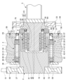
- FIG. 1 is a right side view showing an example of an injection molding machine to which the bearing lubrication structure according to the first embodiment of the present invention is applied, with a part thereof shown in cross section.
- FIG. 3 is a right side view showing a modification of the bearing greasing structure according to the first embodiment, with a portion shown in cross section.
- FIG. 7 is a right side view showing a bearing lubrication structure according to a second embodiment of the present invention, with a portion shown in cross section.
- FIG. 7 is a right side view showing a modification of the bearing lubrication structure according to the second embodiment, with a portion shown in cross section.
- FIG. 7 is a right side view showing a bearing lubrication structure according to a third embodiment of the present invention, with a portion shown in cross section. It is a right view which shows the modification of the greasing structure of the bearing based on 3rd Embodiment, and shows it partially made into a cross section.
- the bearing greasing structure includes a housing 1, an outer bearing 2, a first rotating body 3, an inner bearing 4, and a second rotating body 5.
- a case where the present invention is applied to the injection molding machine 6 will be described.
- the apparatus to which the present invention is applied is not limited to the injection molding machine 6.
- the injection molding machine 6 includes a front plate 7 and a rear plate 8 that are arranged to face each other, a guide rod 9 that connects the front plate 7 and the rear plate 8, and a housing 1 that is slidably provided on the guide rod 9. , a first rotating body 3 rotatably but immovably provided in the axial direction in the housing 1; an injection screw 10 provided in the first rotating body 3; A second rotating body 5 is provided, and a ball nut 11 is provided on the rear plate 8.
- the injection molding machine 6 can move the injection screw 10 by converting the rotational motion of the second rotating body 5 screwed into the ball nut 11 into linear motion and pressing the housing 1.
- the front plate 7 is plate-shaped.
- the front plate 7 is provided with an injection cylinder 12.
- the rear plate 8 is plate-shaped.
- the rear plate 8 has a through hole 13 penetrating in the thickness direction.
- the front plate 7 and the rear plate 8 are connected by a plurality of rod-shaped guide rods 9. Specifically, the rear plate 8 is fixed to one axial end of the guide rod 9 (the right end in FIG. 1), and the other axial end of the guide rod 9 (the left end in FIG. 1). By fixing the front plate 7 to the front plate 7, the front plate 7 and the rear plate 8 are connected while facing each other.
- the housing 1 has a thick plate shape.
- the housing 1 has a plurality of insertion holes 14 penetrating in the thickness direction (also in the axial direction of the guide rod 9).
- the housing 1 is installed on the guide rod 9 by passing the guide rod 9 through the insertion hole 14 .
- a cylindrical bush 15 is provided between the inner peripheral surface of the insertion hole 14 and the outer peripheral surface of the guide rod 9. In this way, the housing 1 is provided on the guide rod 9 so as to be slidable along the axial direction of the guide rod 9.
- the housing 1 has a through hole 16 that penetrates in the thickness direction.
- the through hole 16 is located approximately at the center of the housing 1.
- the through hole 16 is a stepped hole. That is, the through hole 16 has a small diameter hole 17 located at one end in the axial direction and a large diameter hole 18 located at the other end in the axial direction. Since the housing 1 is provided with the through hole 16, in other words, the housing 1 is hollow with an inner peripheral surface.
- the first rotating body 3 has a columnar main body portion 19 and a holding portion 20 for holding down an inner bearing 4, which will be described later.
- the main body part 19 has a stepped cylindrical shape, and includes a large diameter part 21 located on one axial end side of the main body part 19 (the right end side in FIG. 1) and a small diameter part 22 adjacent to the large diameter part 21. have.
- the main body portion 19 has a recessed portion 23 having a circular shape in rear view on one end surface in the axial direction. The recess 23 is open at one end of the main body 19 in the axial direction.
- the recess 23 has a stepped shape and includes a large diameter hole 24 located at one end in the axial direction and a small diameter hole 25 located at the other end in the axial direction. Since the first rotating body 3 is provided with the recess 23, in other words, the first rotating body 3 is hollow with an inner peripheral surface.
- the injection screw 10 is fixed to the other end of the main body 19 in the axial direction with a bolt or the like.
- the holding part 20 is plate-shaped and has a through hole 26 penetrating in the thickness direction.
- the first rotating body 3 is rotatably held in the housing 1 via the outer bearing 2.
- the outer bearing 2 is, for example, a ball bearing.
- the outer bearing 2 includes an adjacent first bearing 27 and a second bearing 28, an annular outer ring spacer 31 connecting an outer ring 29 of the first bearing 27 and an outer ring 30 of the second bearing 28, and the first bearing 27. It has an annular inner ring spacer 34 that connects the inner ring 32 of the second bearing 28 and the inner ring 33 of the second bearing 28 . A cylindrical gap is formed between the outer ring spacer 31 and the inner ring spacer 34.
- the outer bearing 2 having such a configuration is provided in the housing 1 by holding the outer ring 29 of the first bearing 27 and the outer ring 30 of the second bearing 28 on the inner peripheral surface of the large diameter hole 18.
- the outer ring 29 of the first bearing 27 located at one axial end of the outer bearing 2 (the right end in FIG. 1) has a large diameter hole 18 and a small diameter hole.
- the outer ring 30 of the second bearing 28 which is in contact with the step between the second bearing 17 and the other end of the outer bearing 2 in the axial direction, is in contact with a presser part 36 provided on the housing 1 .
- the holding portion 36 has a plate shape and is fixed to the other end surface of the housing 1 in the axial direction with a bolt or the like.
- the holding portion 36 has a through hole 37 that penetrates in the thickness direction. In this way, the outer rings (29, 30) of the outer bearing 2 are held on the inner peripheral surface of the hollow housing 1.
- the main body portion 19 of the first rotating body 3 is held by the inner ring 32 of the first bearing 27 and the inner ring 33 of the second bearing 28. At this time, the outer peripheral surface of the small diameter portion 22 of the main body portion 19 is fixed to the inner ring 32 of the first bearing 27 and the inner ring 33 of the second bearing 28 .
- the inner ring 32 of the first bearing 27 is in contact with the step between the large diameter part 21 and the small diameter part 22, and the inner ring 32 of the first bearing 27 is in contact with the step between the large diameter part 21 and the small diameter part 22.
- the inner ring 33 is in contact with an annular pressing portion 72 provided on the first rotating body 3 .
- the holding portion 72 is fixed to the first rotating body 3 with the first rotating body 3 passing through it.
- the first rotating body 3 is fixed to the inner ring (32, 33) of the outer bearing 2.
- the other axial end of the first rotating body 3 (the left end in FIG. 1) is located on the other axial end side of the through hole 16 of the housing 1. It passes through the opening of and the through hole 37 of the holding part 36.
- the second rotating body 5 is columnar.
- the other end of the second rotating body 5 in the axial direction (the left end in FIG. 1) has a stepped cylindrical shape and includes a large diameter portion 39 and a small diameter portion 40.
- the second rotating body 5 is rotatably supported by the first rotating body 3 via the inner bearing 4 .
- the inner bearing 4 is, for example, a ball bearing. In the first embodiment, a plurality of inner bearings 4 are used, but only one inner bearing 4 may be used.
- the plurality of inner bearings 4 are provided on the inner circumferential surface of the recess 23 of the first rotating body 3 while in contact with each other. At this time, the inner bearing 4 is provided on the first rotating body 3 by holding the outer ring 41 of the inner bearing 4 on the inner peripheral surface of the large diameter hole 24 of the recess 23 . In a state where a plurality of inner bearings 4 are provided in the first rotating body 3, the outer ring 41 of the inner bearing 4 located on the back side of the recess 23 is located at the step between the large diameter hole 24 and the small diameter hole 25. The outer ring 41 of the inner bearing 4 located on the opening side of the recess 23 is in contact with a presser portion 20 provided on the main body portion 19 . The holding portion 20 is fixed to one axial end surface of the main body portion 19 with a bolt or the like. In this way, the outer ring 41 of the inner bearing 4 is held on the inner peripheral surface of the hollow first rotating body 3.
- the small diameter portion 40 of the second rotating body 5 is held by the inner ring 43 of the inner bearing 4 with the second rotating body 5 passing through the through hole 26 of the holding portion 20 of the first rotating body 3. At this time, the outer peripheral surface of the small diameter portion 40 of the second rotating body 5 is fixed to the inner ring 43 of the inner bearing 4.
- the inner ring 43 of the inner bearing 4 located on the opening side of the recess 23 contacts the step between the small diameter part 40 and the large diameter part 39.
- the inner ring 43 of the inner bearing 4 located on the back side of the recess 23 is in contact with an annular pressing portion 45 provided on the small diameter portion 40 of the second rotating body 5.
- the holding portion 45 is fixed to the other axial end of the small diameter portion 40 with the small diameter portion 40 inserted therein.
- the second rotating body 5 is fixed to the inner ring of the inner bearing 4.
- the inner bearing 4 and the outer bearing 2 are arranged in a double arrangement, inside and outside.
- the second rotating body 5 is provided with a male thread on the outer peripheral surface except for the other end in the axial direction.
- the second rotating body 5 is screwed into a ball nut 11 provided on the rear plate 8.
- the ball nut 11 is fixed non-rotatably in the through hole 13 of the rear plate 8.
- the second rotating body 5 screwed into a ball nut 11 provided on the rear plate 8 passes through a through hole 13 in the rear plate 8. That is, one axial end of the second rotating body 5 protrudes from the through hole 13 of the rear plate 8.
- One axial end of the second rotating body 5 passes through an annular load cell 46 provided on the rear plate 8.
- the load cell 46 is fixed to the rear plate 8 with bolts or the like.
- the injection molding machine 6 includes a motor 47 that rotates the first rotating body 3 to which the injection screw 10 is fixed, and a motor 48 that rotates the second rotating body 5.
- the motor 47 is provided in the housing 1.
- a drive pulley 49 is fixed to the drive shaft of the motor 47.
- a belt 51 is wound around a drive pulley 49 provided on the motor 47 and a driven pulley 50 provided at the other axial end of the first rotating body 3 .
- the motor 48 is provided in the housing 1 such that the first rotating body 3 is located between the motors 47 and 48.
- a drive pulley 52 is fixed to the drive shaft of the motor 48.
- a belt 54 is wound around a driving pulley 52 provided on the motor 48 and a driven pulley 53 provided on the second rotating body 5.
- the injection screw 10 can be rotated by driving the motor 47 while the motor 48 is stopped.
- a metering and kneading operation is performed, and the melted resin is fed into the tip of the injection cylinder 12.
- the second rotating body 5 can be rotated by driving the motor 48 while the motor 47 is stopped.
- the housing 1 can be moved toward the injection cylinder 12, and the injection screw 10 can be moved within the injection cylinder 12 to perform injection.
- the bearing greasing structure according to the first embodiment is applied to the injection molding machine 6 as described above.
- the bearing greasing structure includes a hollow housing 1, an outer bearing 2 whose outer ring is held on the inner peripheral surface of the housing 1, and a hollow first rotating body 3 fixed to the inner ring of the outer bearing 2. It includes an inner bearing 4 whose outer ring is held on the inner peripheral surface of the first rotating body 3, and a second rotating body 5 which is fixed to the inner ring of the inner bearing 4.
- the housing 1, the outer bearing 2, the first rotating body 3, the inner bearing 4, and the second rotating body 5 have the configurations described above.
- the housing 1 has a first lubricant passage 55 through which lubricant to be supplied to the inner bearing 4 passes.
- the upstream opening of the first greasing passage 55 opens to the outside of the housing 1 .
- a greasing port 56 consisting of a grease nipple or the like is provided at the opening on the upstream side of the first greasing path 55 .
- a greasing device that automatically supplies lubricant is connected to the greasing port 56 .
- the downstream side of the first greasing passage 55 communicates with a first sealed space 57 between the housing 1 and the first rotating body 3 .
- the first sealed space 57 is formed by sealing the opening of a cylindrical gap located between the inner circumferential surface of the housing 1 and the outer circumferential surface of the first rotating body 3 with a sealing member. Ru.
- the sealing member includes a first sealing material 58 provided on the outside of the first bearing 27 and a second sealing material 59 provided on the outside of the second bearing 28.
- the first sealing material 58 seals one axial end (the right end in FIG. 1) of the cylindrical gap between the outer ring spacer 31 and the inner ring spacer 34.
- the second sealing material 59 seals the other end of the cylindrical gap between the outer ring spacer 31 and the inner ring spacer 34 in the axial direction.
- a first sealed space 57 is formed by sealing the cylindrical gap between the outer ring spacer 31 and the inner ring spacer 34.
- the downstream side of the first greasing passage 55 is provided in the outer ring spacer 31. It communicates with the first sealed space 57 via the outer through hole 60 .
- the first rotating body 3 has a second greasing passage 61 through which the lubricant flowing from the first greasing passage 55 through the first sealed space 57 passes.
- the upstream side of the second greasing passage 61 communicates with the first sealed space 57 .
- the cylindrical gap between the outer ring spacer 31 and the inner ring spacer 34 is the first sealed space 57. Therefore, the upstream side of the second greasing passage 61 is communicated with the first sealed space 57 via the inner through hole 62 provided in the inner ring spacer 34 .
- the downstream side of the second greasing passage 61 communicates with a second sealed space 63 between the first rotating body 3 and the second rotating body 5 .
- the second sealed space 63 is configured by sealing an opening of a cylindrical gap located between the inner circumferential surface of the first rotating body 3 and the outer circumferential surface of the second rotating body 5 with a sealing member 64. formed by.
- the sealing member 64 seals the gap between the inner circumferential surface of the first rotating body 3 and the outer circumferential surface of the second rotating body 5 on the opening side of the recess 23 .
- the sealing member 64 has an annular shape and is provided between the inner circumferential surface of the holding portion 20 of the first rotary body 3 and the outer circumferential surface of the large diameter portion 39 of the second rotary body 5 .
- the sealing member 64 is a conventionally known oil seal, but is not limited thereto.
- the inner bearing 4 is disposed within the second sealed space 63 thus formed.
- the first rotating body 3 passes through the housing 1, so it has an exposed surface 65 exposed from the housing 1.
- the exposed surface 65 is the outer peripheral surface of the holding portion 20 of the first rotating body 3.
- the first rotating body 3 has a discharge path 66 that discharges the lubricant in the second sealed space 63 to the outside of the housing 1 .
- the discharge path 66 is provided, for example, in the holding portion 20 of the first rotating body 3.
- the discharge path 66 is a flow path through which the lubricant that has passed through the inner bearing 4 is discharged. Therefore, the upstream side of the discharge path 66 is communicated with the portion between the inner bearing 4 and the sealing member 64.
- the outlet of the discharge passage 66 is open to the exposed surface 65.
- the lubricant supplied from the lubrication device flows into the first sealed space 57 through the first lubrication path 55.
- the lubricant flows from the first sealed space 57 into the second sealed space 63 through the second greasing path 61 .
- lubricant is supplied to the inner bearing 4.
- the lubricant is discharged to the outside of the housing 1 through the discharge passage 66. Therefore, according to the greasing structure of the first embodiment, the inner bearing 4 on which the inner ring 43 and the outer ring 41 rotate can be easily lubricated during operation of the injection molding machine 6 with a simple configuration. It is also suitable for automation.
- the outlet of the discharge passage 66 is open to the exposed surface 65. Therefore, according to the lubricating structure of the first embodiment, the structure can be simpler than the structure in which lubricant is discharged through the housing 1.
- the greasing structure of this modification includes a plurality of first greasing passages 55 and a plurality of second greasing passages 61.
- the greasing structure of this modification includes two first greasing passages 55, 55 and second greasing passages 61, 61 corresponding to the two first greasing passages 55, 55, respectively. It has The two first greasing passages 55, 55 are provided at positions facing each other with the first rotating body 3 interposed therebetween. The two second greasing passages 61, 61 are provided at opposing positions with the first rotating body 3 in between. Accordingly, two outer through holes 60, 60 are provided in the outer ring spacer 31, and two inner through holes 62, 62 are provided in the inner ring spacer 34.
- the lubricant is supplied to the second sealed space 63 from two supply paths. Therefore, according to the lubricating structure of this modification, lubricant can be efficiently supplied into the second sealed space 63.
- FIG. 3 a bearing greasing structure according to a second embodiment of the present invention will be described using FIG. 3. Note that components having the same reference numerals as those in the first embodiment have the same functions, and therefore descriptions thereof may be omitted below.
- the greasing structure of the second embodiment differs from the first embodiment in the configuration of the first sealed space 57.
- the through hole 16 of the housing 1 is a stepped hole.
- the through hole 16 has a small diameter hole 67 located at one axial end of the through hole 16 and a large diameter hole 69 located at the other axial end of the through hole 16 .
- the plurality of outer bearings 2 are provided in the large diameter hole 69 of the through hole 16 in a state in which they are in contact with each other. At this time, the outer ring 79 of the outer bearing 2 is held on the inner peripheral surface of the large diameter hole 69, so that the outer bearing 2 is provided in the housing 1. In a state where a plurality of outer bearings 2 are provided in the housing 1, the outer ring 79 of the outer bearing 2 located on one axial end side of the through hole 16 contacts the step between the large diameter hole 69 and the small diameter hole 67. The outer ring 79 of the outer bearing 2 located on the other axial end side of the through hole 16 is in contact with the pressing portion 36 provided on the housing 1 .
- the holding portion 36 has a thick plate shape and is fixed to the other end surface of the housing 1 in the axial direction with a bolt or the like.
- the holding portion 36 has a through hole 37 that penetrates in the thickness direction.
- the through hole 37 is a stepped hole.
- the main body portion 19 of the first rotating body 3 is held by the inner ring 80 of the outer bearing 2. At this time, the outer peripheral surface of the small diameter portion 22 of the main body portion 19 is fixed to the inner ring 80 of the outer bearing 2.
- the inner ring 80 of the outer bearing 2 located on one axial end side of the through hole 16 is located at the stepped portion between the large diameter portion 21 and the small diameter portion 22.
- the inner ring 80 of the outer bearing 2 which is in contact with the other end of the through hole 16 in the axial direction, is in contact with an annular pressing portion 72 provided on the first rotating body 3 .
- the first sealed space 57 is configured by sealing an opening at one end in the axial direction of a cylindrical gap located between the housing 1 and the first rotating body 3 with an annular third sealing material 74. It is formed by sealing the opening on the other axial end side of the cylindrical gap located between the first rotation body 1 and the first rotating body 3 with an annular fourth sealing material 75.
- the fourth sealing material 75 seals the gap between the inner circumferential surface of the small diameter hole of the through hole 37 of the holding portion 36 and the outer circumferential surface of the first rotating body 3 .
- the outer bearing 2 is constructed such that the first portion 76 on one axial end side of the first sealed space 57 and the second portion 77 on the other axial end side of the first sealed space 57 remain. It is arranged within the sealed space 57. In this case, the downstream side of the first greasing passage 55 is communicated with the first portion 76 . The upstream side of the second greasing passage 61 communicates with the second portion 77 .
- the lubricant supplied from the lubrication device flows into the first portion 76 of the first sealed space 57 through the first lubrication path 55.
- the lubricant flows from the first portion 76 of the first sealed space 57 through the outer bearing 2 to the second portion 77 .
- the lubricant flows from the second portion 77 of the first sealed space 57 into the second sealed space 63 through the second greasing passage 61 .
- lubricant is supplied to the inner bearing 4.
- the lubricant is discharged to the outside of the housing 1 through the discharge passage 66.
- the greasing structure of this modification includes a plurality of first greasing passages 55 and a plurality of second greasing passages 61.
- the greasing structure of this modification includes two first greasing passages 55, 55 and second greasing passages 61, 61 corresponding to the two first greasing passages 55, 55, respectively. It has The two first greasing passages 55, 55 are provided at positions facing each other with the first rotating body 3 interposed therebetween. The two second greasing passages 61, 61 are provided at positions facing each other with the first rotating body 3 interposed therebetween.
- FIG. 5 a bearing greasing structure according to a third embodiment of the present invention will be described using FIG. 5. Note that components having the same reference numerals as those in the first embodiment have the same functions, and therefore descriptions thereof may be omitted below.
- the greasing structure of the third embodiment differs from the first embodiment in the configuration of the first sealed space 57.
- the annular fifth sealing member 78 is provided between the housing 1 and the first rotating body 3 so that a gap is formed between the fifth sealing member 78 and the outer bearing 2.
- the fifth sealing material 78 is provided so that a gap is formed between it and the first bearing 27 .
- a first sealed space 57 is formed between the first sealing material 58 and the fifth sealing material 78 of the first bearing 27.
- the fifth sealing material 78 is provided between the housing 1 and the first rotating body 3 so that a gap is formed between the fifth sealing member and the sealing member provided on the outer bearing 2. .
- the outer bearing 2 is arranged adjacent to the first sealed space 57.
- the outer bearing 2 is a bearing having an outer ring spacer 31 and an inner ring spacer 34, it may be a normal ball bearing. In this case, the outer bearing is provided with a sealing member.
- the greasing structure of this modification includes a plurality of first greasing passages 55 and a plurality of second greasing passages 61.
- the greasing structure of this modification includes two first greasing passages 55, 55 and second greasing passages 61, 61 corresponding to the two first greasing passages 55, 55, respectively. It has The two first greasing passages 55, 55 are provided at positions facing each other with the first rotating body 3 interposed therebetween. The two second greasing passages 61, 61 are provided at positions facing each other with the first rotating body 3 interposed therebetween.
- the number of second greasing passages 61 may be greater than the number of first greasing passages 55.
Landscapes
- Engineering & Computer Science (AREA)
- General Engineering & Computer Science (AREA)
- Mechanical Engineering (AREA)
- Rolling Contact Bearings (AREA)
Priority Applications (4)
| Application Number | Priority Date | Filing Date | Title |
|---|---|---|---|
| CN202280097842.6A CN119487312A (zh) | 2022-08-01 | 2022-08-01 | 轴承的供脂构造 |
| JP2024538544A JPWO2024028950A1 (https=) | 2022-08-01 | 2022-08-01 | |
| PCT/JP2022/029521 WO2024028950A1 (ja) | 2022-08-01 | 2022-08-01 | 軸受の給脂構造 |
| DE112022007167.2T DE112022007167T5 (de) | 2022-08-01 | 2022-08-01 | Schmierstruktur für Lager |
Applications Claiming Priority (1)
| Application Number | Priority Date | Filing Date | Title |
|---|---|---|---|
| PCT/JP2022/029521 WO2024028950A1 (ja) | 2022-08-01 | 2022-08-01 | 軸受の給脂構造 |
Publications (1)
| Publication Number | Publication Date |
|---|---|
| WO2024028950A1 true WO2024028950A1 (ja) | 2024-02-08 |
Family
ID=89848628
Family Applications (1)
| Application Number | Title | Priority Date | Filing Date |
|---|---|---|---|
| PCT/JP2022/029521 Ceased WO2024028950A1 (ja) | 2022-08-01 | 2022-08-01 | 軸受の給脂構造 |
Country Status (4)
| Country | Link |
|---|---|
| JP (1) | JPWO2024028950A1 (https=) |
| CN (1) | CN119487312A (https=) |
| DE (1) | DE112022007167T5 (https=) |
| WO (1) | WO2024028950A1 (https=) |
Citations (3)
| Publication number | Priority date | Publication date | Assignee | Title |
|---|---|---|---|---|
| JPS57184222U (https=) * | 1981-05-20 | 1982-11-22 | ||
| JPH06330935A (ja) * | 1993-05-24 | 1994-11-29 | Mitsubishi Electric Corp | ロール装置 |
| JP2004092842A (ja) * | 2002-09-03 | 2004-03-25 | Sumitomo Heavy Ind Ltd | 潤滑装置 |
-
2022
- 2022-08-01 WO PCT/JP2022/029521 patent/WO2024028950A1/ja not_active Ceased
- 2022-08-01 JP JP2024538544A patent/JPWO2024028950A1/ja active Pending
- 2022-08-01 DE DE112022007167.2T patent/DE112022007167T5/de active Pending
- 2022-08-01 CN CN202280097842.6A patent/CN119487312A/zh active Pending
Patent Citations (3)
| Publication number | Priority date | Publication date | Assignee | Title |
|---|---|---|---|---|
| JPS57184222U (https=) * | 1981-05-20 | 1982-11-22 | ||
| JPH06330935A (ja) * | 1993-05-24 | 1994-11-29 | Mitsubishi Electric Corp | ロール装置 |
| JP2004092842A (ja) * | 2002-09-03 | 2004-03-25 | Sumitomo Heavy Ind Ltd | 潤滑装置 |
Also Published As
| Publication number | Publication date |
|---|---|
| JPWO2024028950A1 (https=) | 2024-02-08 |
| CN119487312A (zh) | 2025-02-18 |
| DE112022007167T5 (de) | 2025-02-27 |
Similar Documents
| Publication | Publication Date | Title |
|---|---|---|
| DE60121884T2 (de) | Lager und Dichtungsvorrichtung sowie deren Montage | |
| JP4542114B2 (ja) | 流体送給機構における回転シール機構およびロータリジョイント | |
| US9004890B2 (en) | Gear wheel pump | |
| JPH05126060A (ja) | 歯車ポンプ | |
| CN107532698B (zh) | 滚珠丝杠 | |
| JP2009138897A (ja) | 転がり軸受およびその潤滑方法 | |
| WO2024028950A1 (ja) | 軸受の給脂構造 | |
| CN113877773B (zh) | 高精度螺杆阀 | |
| US9289732B2 (en) | Dynamic mixer | |
| US20150152966A1 (en) | Rotor shaft seal assembly | |
| JP4629636B2 (ja) | 流体送給機構における回転シール機構およびロータリジョイント | |
| CN100513788C (zh) | 齿轮泵 | |
| JPH07317885A (ja) | 遊星歯車用回転支持装置 | |
| CN113202490B (zh) | 一种盾构机用水射流回转接头 | |
| JPH11287305A (ja) | 送りネジ装置 | |
| KR100335319B1 (ko) | 로터리 조인트 | |
| CN208816621U (zh) | 丝杆装置的润滑结构 | |
| CN111674462A (zh) | 一种转向器液压结构总成 | |
| RU2423620C2 (ru) | Дозирующий шестеренный насос | |
| DE102017206686B4 (de) | Lageranordnung zur Lagerung einer Getriebewelle | |
| DE112023006045T5 (de) | Gleichläufiger Scrollverdichter | |
| CN201747422U (zh) | 循环润滑机油泵 | |
| JP2010096317A (ja) | ボールねじ装置 | |
| CN109070032B (zh) | 密闭式混合搅拌机的防漏装置 | |
| JP3249207U (ja) | ボールねじ |
Legal Events
| Date | Code | Title | Description |
|---|---|---|---|
| 121 | Ep: the epo has been informed by wipo that ep was designated in this application |
Ref document number: 22953939 Country of ref document: EP Kind code of ref document: A1 |
|
| WWE | Wipo information: entry into national phase |
Ref document number: 2024538544 Country of ref document: JP |
|
| WWE | Wipo information: entry into national phase |
Ref document number: 112022007167 Country of ref document: DE |
|
| WWE | Wipo information: entry into national phase |
Ref document number: 202280097842.6 Country of ref document: CN |
|
| WWP | Wipo information: published in national office |
Ref document number: 202280097842.6 Country of ref document: CN |
|
| WWP | Wipo information: published in national office |
Ref document number: 112022007167 Country of ref document: DE |
|
| 122 | Ep: pct application non-entry in european phase |
Ref document number: 22953939 Country of ref document: EP Kind code of ref document: A1 |