WO2024024452A1 - コネクタ - Google Patents
コネクタ Download PDFInfo
- Publication number
- WO2024024452A1 WO2024024452A1 PCT/JP2023/025255 JP2023025255W WO2024024452A1 WO 2024024452 A1 WO2024024452 A1 WO 2024024452A1 JP 2023025255 W JP2023025255 W JP 2023025255W WO 2024024452 A1 WO2024024452 A1 WO 2024024452A1
- Authority
- WO
- WIPO (PCT)
- Prior art keywords
- elastic piece
- connector
- circumferential end
- circumferential
- conductor
- Prior art date
- Legal status (The legal status is an assumption and is not a legal conclusion. Google has not performed a legal analysis and makes no representation as to the accuracy of the status listed.)
- Ceased
Links
Images


Classifications
-
- H—ELECTRICITY
- H01—ELECTRIC ELEMENTS
- H01R—ELECTRICALLY-CONDUCTIVE CONNECTIONS; STRUCTURAL ASSOCIATIONS OF A PLURALITY OF MUTUALLY-INSULATED ELECTRICAL CONNECTING ELEMENTS; COUPLING DEVICES; CURRENT COLLECTORS
- H01R13/00—Details of coupling devices of the kinds covered by groups H01R12/70 or H01R24/00 - H01R33/00
- H01R13/02—Contact members
- H01R13/10—Sockets for co-operation with pins or blades
- H01R13/11—Resilient sockets
-
- H—ELECTRICITY
- H01—ELECTRIC ELEMENTS
- H01R—ELECTRICALLY-CONDUCTIVE CONNECTIONS; STRUCTURAL ASSOCIATIONS OF A PLURALITY OF MUTUALLY-INSULATED ELECTRICAL CONNECTING ELEMENTS; COUPLING DEVICES; CURRENT COLLECTORS
- H01R24/00—Two-part coupling devices, or either of their cooperating parts, characterised by their overall structure
- H01R24/38—Two-part coupling devices, or either of their cooperating parts, characterised by their overall structure having concentrically or coaxially arranged contacts
- H01R24/40—Two-part coupling devices, or either of their cooperating parts, characterised by their overall structure having concentrically or coaxially arranged contacts specially adapted for high frequency
- H01R24/50—Two-part coupling devices, or either of their cooperating parts, characterised by their overall structure having concentrically or coaxially arranged contacts specially adapted for high frequency mounted on a PCB [Printed Circuit Board]
-
- H—ELECTRICITY
- H01—ELECTRIC ELEMENTS
- H01R—ELECTRICALLY-CONDUCTIVE CONNECTIONS; STRUCTURAL ASSOCIATIONS OF A PLURALITY OF MUTUALLY-INSULATED ELECTRICAL CONNECTING ELEMENTS; COUPLING DEVICES; CURRENT COLLECTORS
- H01R24/00—Two-part coupling devices, or either of their cooperating parts, characterised by their overall structure
- H01R24/38—Two-part coupling devices, or either of their cooperating parts, characterised by their overall structure having concentrically or coaxially arranged contacts
- H01R24/40—Two-part coupling devices, or either of their cooperating parts, characterised by their overall structure having concentrically or coaxially arranged contacts specially adapted for high frequency
-
- H—ELECTRICITY
- H01—ELECTRIC ELEMENTS
- H01R—ELECTRICALLY-CONDUCTIVE CONNECTIONS; STRUCTURAL ASSOCIATIONS OF A PLURALITY OF MUTUALLY-INSULATED ELECTRICAL CONNECTING ELEMENTS; COUPLING DEVICES; CURRENT COLLECTORS
- H01R2103/00—Two poles
Definitions
- the present disclosure relates to a connector.
- Patent Document 1 discloses a coaxial connector that includes contacts, a synthetic resin insulator that holds the contacts, and a metal shell that further accommodates the insulators.
- the metal shell has a substantially cylindrical fitting portion that fits into a mating male connector.
- an object of the present disclosure is to enable a conductor for a connector to be manufactured at low cost and to obtain a desired contact load when connecting to a mating member.
- a connector of the present disclosure includes a connector conductor including a cylindrical portion and an elastic piece extending from an opening edge of the cylindrical portion, wherein the cylindrical portion has a first circumferential end portion and an elastic piece extending from an opening edge of the cylindrical portion.
- a cylinder-forming part forming a cylinder shape together with a first circumferential end; and a second cylinder-forming part that is continuous with the cylinder-forming part on the opposite side of the first circumferential end and overlapped with the first circumferential end.
- a circumferential end; and a caulking portion that keeps the first circumferential end and the second circumferential end in an overlapping state, and at least a portion of the elastic piece A connector extending from the end.
- a conductor for a connector can be manufactured at low cost, and a desired contact load can be easily obtained when connecting to a mating member.
- FIG. 1 is a perspective view showing a device including a coaxial connector according to a first embodiment.
- FIG. 2 is a sectional view taken along the line II--II in FIG.
- FIG. 3 is a perspective view of the coaxial connector.
- FIG. 4 is an exploded perspective view showing the coaxial connector.
- FIG. 5 is a perspective view showing the outer conductor.
- FIG. 6 is a bottom view showing the outer conductor.
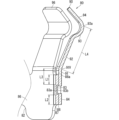
- FIG. 7 is a sectional view taken along the line VII-VII in FIG.
- the connector of the present disclosure is as follows.
- a connector comprising a conductor for a connector including a cylindrical portion and an elastic piece extending from an opening edge of the cylindrical portion, the cylindrical portion having a first circumferential end and a first circumferential end. a cylinder-forming part forming a cylinder shape together with the directional end; and a second circumferential end that is continuous with the cylinder-forming part on the opposite side of the first circumferential end and overlapped with the first circumferential end. and a caulking portion that keeps the first circumferential end and the second circumferential end in an overlapping state, and at least a portion of the elastic piece is separated from the first circumferential end. It is an extending connector.
- the cylindrical portion includes a first circumferential end, a cylindrical forming portion that forms a cylindrical shape together with the first circumferential end, and a cylindrical portion on the side opposite to the first circumferential end with respect to the cylindrical forming portion. It has a second circumferential end portion that is continuous and overlaps the first circumferential end portion, and a caulking portion that maintains the first circumferential end portion and the second circumferential end portion in an overlapping state. Therefore, the connector conductor can be manufactured at a lower cost compared to the case where the connector conductor is formed by cutting or welding the plate materials.
- the proximal end of the elastic piece At least a portion is firmly held by the overlapping structure of the first circumferential end and the second circumferential end. This makes it easy to obtain a desired contact load when connecting the connector conductor to a mating member.
- more than half of the base end of the elastic piece in the width direction may be continuous with the first circumferential end.
- the caulking portion may be separated from the elastic piece.
- the distance between the caulking portion and the elastic piece may be greater than or equal to the distance between the edge of the cylindrical portion on the opposite side from the elastic piece and the caulking portion. good.
- the contact portion faces outward in the radial direction of the cylindrical portion, and the first circumferential end portion and the cylindrical forming portion have a cylindrical shape with the same diameter.
- the second circumferential end may be overlapped inside the first circumferential end and protrude further inward than the cylinder forming portion.
- the elastic piece can be effectively received. Since the first circumferential end and the cylinder forming part are continuous so as to form a cylinder shape with the same diameter, when the other elastic piece is extended from the cylinder forming part, the elastic piece and the other elastic piece It is easy to maintain the same elastic properties. Furthermore, by making the second circumferential end protrude more toward the inner circumferential side than the tube-forming portion, the second circumferential end can be easily positioned with respect to the member inside the tube.
- the elastic piece has a base end portion extending from a base end of the elastic piece along the axial direction of the cylindrical portion, and a base end portion extending from the base end of the elastic piece. an inclined part extending from a distal end of the part so as to be inclined with respect to the axial direction, and an edge of the second circumferential end on the side from which the elastic piece extends is connected to a proximal end of the elastic piece; It may be located between the boundary between the base end portion and the inclined portion.
- the base end portion of the elastic piece can be effectively received by the second circumferential end portion.
- the connector conductor further includes at least one additional elastic piece extending from the opening edge of the cylindrical part, and the elastic piece and the at least one additional elastic piece may be located side by side with an interval in the circumferential direction of the cylindrical portion.
- the connector conductor can be electrically connected to the mating conductor well.
- the elastic piece and the at least one additional elastic piece may be arranged at equal intervals in the circumferential direction of the cylindrical portion.
- the contact load between the elastic piece and the at least one additional elastic piece on the mating conductor can be made as similar as possible, and the connector conductor can be electrically connected to the mating conductor well.
- the connector conductor in a connector that includes a connector conductor as an inner conductor, an insulator housing the inner conductor, and an outer conductor housing the insulator, the connector conductor can be electrically connected to the mating conductor in a good manner.
- the insulator may have a recess on the outer peripheral side, and the second circumferential end may fit into the recess.
- the connector conductor can be positioned with respect to the insulator using the second circumferential end.
- a connector according to an embodiment will be described.
- a coaxial connector is a connector in which an outer conductor and an inner conductor therein are coaxially located. It is not essential that the connector be a coaxial connector; for example, a plurality of inner conductors may be located within an outer conductor.
- FIG. 1 is a perspective view showing a device 10 including a coaxial connector 60.
- FIG. 2 is a sectional view taken along the line II--II in FIG.
- the device 10 is, for example, a camera device.
- the camera device is, for example, an in-vehicle device.
- the device 10 does not have to be a camera device.
- the device 10 includes a case 12 and electrical components 20.
- An electrical component 20 is housed within the case 12.
- a coaxial connector 60 is fixed to the electrical component 20.
- the case 12 includes a first case 13 and a second case 14.
- the first case 13 and the second case 14 are made of resin, for example.
- the first case 13 and the second case 14 are combined to form a rectangular parallelepiped box-shaped case 12 that accommodates the electrical component 20.
- the device 10 is a camera device, it is assumed that the first case 13 has a lens or window for imaging, and the second case 14 has a coaxial connector 30 for external connection.
- the external connection coaxial connector 30 is a coaxial connector for connecting the electrical component 20 and an external electrical component.
- the external connection coaxial connector 30 is a coaxial connector to which a cable connected to an external electrical component is connected.
- the cable to which the external connection coaxial connector 30 is connected is, for example, a coaxial cable.
- a holding cylinder portion 16 is provided protruding from the bottom portion 15 of the case 12.
- the holding cylinder portion 16 is a cylinder and projects outward from the center of the bottom portion 15 .
- the inner opening of the holding cylinder part 16 opens into the second case 14, and the outer opening of the holding cylinder part 16 opens to the outside of the second case 14.
- a holding partition part 17 is formed in the middle part of the holding cylinder part 16 in the direction along the central axis X (axial direction). In this embodiment, the holding partition part 17 is formed at the middle part of the holding cylinder part 16 in the direction along the central axis X, and at a position closer to the inner opening.
- the holding partition part 17 partitions a space on the inner opening side of the holding cylinder part 16 and a space on the outer opening side.
- a holding hole 17h is formed in the holding partition portion 17, and the external connection coaxial connector 30 is inserted into and held in the holding hole 17h.
- a locking protrusion 18a for holding a cable connector attached to an end of a cable is formed on the outer circumference of the holding cylinder 16. It is not essential that the locking protrusion 18a be formed.
- the coaxial connector 30 for external connection includes an inner conductor 32 for external connection, an insulator 34 for external connection, and an outer conductor 36 for external connection.
- the external connection inner conductor 32 is formed into an elongated rod shape and is made of a conductive material such as metal.
- the external connection insulator 34 is made of an insulator such as resin, and surrounds the external connection inner conductor 32 .
- the external connection insulator 34 is a dielectric.
- the external connection outer conductor 36 is made of a conductive material such as metal.
- the outer conductor 36 for external connection is formed in a cylindrical shape surrounding the insulator 34 for external connection.
- the electrical component 20 is, for example, a mounting board on which electronic components are mounted.
- the electrical components 20 are assumed to be a circuit board 21 and an image sensor 22 mounted on the circuit board 21.
- the image sensor 22 faces an imaging lens or window of the first case 13, and rotates the lens or window to image the outside scenery.
- the first case 13 side toward which the image sensor 22 faces may be referred to as the front side
- the second case 14 side opposite to the first case 13 side may be referred to as the rear side.
- the coaxial connector 60 is located on the surface of the circuit board 21 opposite to the image sensor 22.
- the coaxial connector 60 is fixed to the circuit board 21 and protrudes from the circuit board 21 toward the external connection coaxial connector 30.
- the coaxial connector 60 is a board-side coaxial connector.
- the coaxial connector 60 includes, for example, an inner conductor 62, an insulator 70, and an outer conductor 80.
- a movable inner conductor 42 which will be described later, is connected to the inner conductor 62.
- Insulator 70 surrounds inner conductor 62 .
- the outer conductor 80 surrounds the insulator 70. That is, the inner conductor 62, the insulator 70, and the outer conductor 80 are arranged concentrically in this order from the center toward the outer circumference.
- the coaxial connector 60 and the external connection coaxial connector 30 are connected via the relay connector 40.
- the relay connector 40 includes, for example, a movable inner conductor 42, a movable insulator 44, and a movable outer conductor 46.
- a movable inner conductor 42 is surrounded by a movable insulator 44 .
- a dielectric can be understood as a type of insulator, and the movable insulator 44 may be a dielectric.
- a movable outer conductor 46 surrounds the movable insulator 44 .
- the movable inner conductor 42 is an example of a mating inner conductor connected to the inner conductor 62
- the movable outer conductor 46 is an example of a mating outer conductor connected to the outer conductor 80
- the relay connector 40 is a coaxial connector
- 60 is an example of a mating coaxial connector connected to the connector 60.
- the relay connector 40 is connected to the coaxial connector 60 with the movable inner conductor 42 being inserted and connected to the inner conductor 62 and the outer conductor 80 being inserted and connected to the movable outer conductor 46. In this state, the relay connector 40 further protrudes from the coaxial connector 60 toward the external connection coaxial connector 30.
- the inner conductor 32 for external connection is inserted and connected to the movable inner conductor 42, and the movable outer conductor 46 is inserted and connected to the outer conductor 36 for external connection, so that the relay connector 40 is connected to the coaxial connector 30 for external connection. Connected. Thereby, the relay connector 40 makes a relay connection between the coaxial connector 60 and the external connection coaxial connector 30.
- the movable inner conductor 42 is inserted and connected in an inclined state with respect to the inner conductor 62.
- the outer conductor 80 is inserted and connected to the movable outer conductor 46 in an inclined state. That is, the relay connector 40 can be connected in an inclined state with respect to the coaxial connector 60 (see arrow P1 in FIG. 2). This allows the coaxial By tilting the relay connector 40 with respect to the connector 60, the positional shift is absorbed.
- FIG. 3 is a perspective view showing the coaxial connector 60.
- FIG. 4 is an exploded perspective view showing the coaxial connector 60.
- the coaxial connector 60 includes, for example, the inner conductor 62, the insulator 70, and the outer conductor 80.
- the inner conductor 62 is an elongated conductive member (see FIGS. 2 and 4).
- the inner conductor 62 is formed by pressing a metal plate. More specifically, the inner conductor 62 includes a proximal tube portion 64 and a plurality of elastic pieces 66.
- the base end cylinder portion 64 is formed in a cylindrical shape, more specifically, in a cylindrical shape.
- the proximal tube portion 64 is housed on the proximal side of the insulator 70 .
- the tip is the end to which the movable inner conductor 42 is connected, and the base end is the end opposite to the tip, here, the end facing the circuit board 21. .
- An extension piece 64a extends from the proximal side edge of the proximal tubular portion 64 toward the inside of the proximal tubular portion 64.
- the extension piece 64a is soldered to the circuit of the circuit board 21, for example.
- the base tube portion 64 may have a positioning convex portion 64P that partially protrudes toward the outer circumferential side in the circumferential direction.
- the inner conductor 62 may be positioned with respect to the insulator 70 by fitting the positioning convex portion 64P into a recess in the insulator 70.
- a locking protrusion 64b is provided protruding from the base end cylinder portion 64.
- the locking protrusion 64b partially protrudes from the outer periphery of the proximal tube portion 64.
- the locking protrusion 64b is formed in such a shape that its protrusion dimension gradually increases from the distal end of the proximal end tube portion 64 toward the proximal end.
- the plurality of elastic pieces 66 further protrude toward the distal end from the distal opening of the proximal tube portion 64.
- the plurality of elastic pieces 66 are positioned at equal intervals around the central axis X of the cylindrical portion 72.
- the two elastic pieces 66 face each other around the central axis X of the proximal tube portion 64 .
- the movable inner conductor 42 of the relay connector 40 is inserted between the two elastic pieces 66 from their distal ends.
- the movable inner conductor 42 is sandwiched between the two elastic pieces 66, thereby connecting the movable inner conductor 42 to the inner conductor 62.
- the insulator 70 is made of resin or the like.
- a dielectric can be understood as a type of insulator, and the insulator 70 may be a dielectric.
- the insulator 70 is, for example, a molded resin part.
- the insulator 70 includes a cylindrical portion 72 and a tip guide portion 76.
- the cylindrical portion 72 is formed into a cylindrical shape that can accommodate the inner conductor 62.
- the cylindrical portion 72 is formed in a cylindrical shape, and a cylindrical space is formed inside thereof.
- An inner conductor is housed within the cylindrical space.
- the outer circumferential surface of the cylindrical portion 72 is formed into a circumferential shape centered on the central axis X.
- An outer conductor 80 is arranged on the outer peripheral side of the cylindrical portion 72 .
- a positioning recess 72g is formed in a part of the outer circumference of the cylinder portion 72 in the circumferential direction.
- the recess 72g has a pair of side surfaces 72g1 facing each other in the circumferential direction of the cylindrical portion 72 and a surface 72g2 facing toward the proximal end of the cylindrical portion 72 (see FIG. 4).
- a second circumferential end portion 88 which will be described later, fits into the recess 72g.
- the position of the second circumferential end portion 88 is regulated by the pair of side surfaces 72g1 and 72g2. This restricts the outer conductor 80 fitted onto the insulator 70 from rotating around the central axis X and from moving toward the tip side with respect to the insulator 70 .
- a plurality (four in this case) of elongated protrusions 72a are formed on the outer peripheral surface of the cylindrical portion 72.
- Each protrusion 72a extends parallel to the central axis X. It is preferable that the plurality of protrusions 72a be located at equal intervals around the central axis X on the outer circumferential surface of the cylindrical portion 72.
- the protruding portions 72a contact the inner circumferential surface of the cylindrical portion 82 at positions dispersed in the circumferential direction.
- the tip guide portion 76 is located on the tip side of the cylindrical portion 72.
- the tip guide portion 76 has an insertion hole 77 into which the movable inner conductor 42 can be inserted.
- the central axis X of the cylindrical portion 72 coincides with the central axis X of the insertion hole 77.
- the inner circumferential surface of the insertion hole 77 is formed in a tapered shape whose diameter gradually decreases toward the inside of the cylindrical portion 72.
- the tip of the movable inner conductor 42 is guided by the tapered inner peripheral surface of the insertion hole 77 toward between the plurality of elastic pieces 66 .
- the outer circumferential portion of the tip guide portion 76 projects further to the outer circumferential side than the cylindrical portion 72.
- An outer circumferential guide surface 78 whose diameter gradually increases toward the proximal end is formed on the outer circumference of the distal guide portion 76 .
- the outer guide surface 78 can serve to guide the cylindrical portion of the movable outer conductor 46 to the outside of the outer conductor 80.
- the annular back surface of the distal guide portion 76 facing the proximal end extends perpendicularly to the central axis X of the cylindrical portion 72.
- An elastic piece 90 which will be described later, can be elastically deformed in the radial direction of the cylindrical portion 72 on the proximal end side of the annular back surface.
- the outer conductor 80 is made of a conductive material such as metal, and surrounds the insulator 70.
- the outer conductor 80 is formed, for example, by pressing a metal plate.
- the outer conductor 80 includes a cylindrical portion 82 and an elastic piece 90. In this embodiment, the outer conductor 80 further includes an additional elastic piece 96.
- the cylindrical portion 82 is formed into a cylindrical shape in which the cylindrical portion 72 can be placed.
- An elastic piece 90 and an additional elastic piece 96 extend from the opening edge on the distal end side of the cylindrical portion 82 .
- the elastic piece 90 and the additional elastic piece 96 are arranged between the tip guide part 76 and the cylinder part 82 so as to surround the cylinder part 72 .
- the movable outer conductor 46 of the relay connector 40 is guided toward the outer periphery of the elastic piece 90 and the additional elastic piece 96 by the outer guide surface 78 of the tip guide portion 76 .
- the elastic piece 90 and the additional elastic piece 96 come into contact with the movable outer conductor 46 from the inner peripheral side, and the outer conductor 80 and the movable outer conductor 46 are connected.
- FIG. 5 is a perspective view showing the outer conductor 80.
- FIG. 6 is a bottom view showing the outer conductor 80.
- FIG. 7 is a sectional view taken along the line VII-VII in FIG.
- the outer conductor 80 includes a cylindrical portion 82 and an elastic piece 90 extending from the opening edge on the distal end side of the cylindrical portion 82.
- the cylindrical portion 82 is a portion that is externally fitted onto the insulator 70.
- the cylindrical portion 82 is held at a fixed position relative to the insulator 70 and plays a role of supporting the outer conductor 80 at a fixed position relative to the insulator 70. Further, for example, if the proximal opening of the cylindrical portion 82 is soldered to a circuit on the circuit board 21, for example, a ground circuit, it can serve to ground the movable outer conductor 46 to the ground circuit.
- the cylindrical portion 82 includes a first circumferential end 84 , a cylindrical forming portion 86 , and a second circumferential end 88 .
- the cylinder forming portion 86 has a partial cylinder shape.
- a first circumferential end portion 84 is continuous with one circumferential end side of the cylinder forming portion 86 .
- the tube forming portion 86 has a tube shape together with the first circumferential end portion 84 . More specifically, the first circumferential end portion 84 and the cylinder forming portion 86 have a cylinder shape for one circumference.
- the second circumferential end 88 is continuous with the cylinder forming portion 86 on the opposite side of the first circumferential end 84 .
- the second circumferential end 88 overlaps the first circumferential end 84 .
- the first circumferential end portion 84, the cylinder forming portion 86, and the second circumferential end portion 88 are formed in a shape that exceeds the cylindrical shape of one circumference, and the cylindrical portion 82 Both ends are overlapped.
- One of the overlapping portions is a first circumferential end 84 and the other is a second circumferential end 88.
- the second circumferential end 88 may overlap the first circumferential end 84 on the inner circumferential side or on the outer circumferential side. It is preferable that the second circumferential end 88 is overlapped with the first circumferential end 84 on the opposite side to the direction of the contact portion 93a. In this embodiment, the contact portion 93a faces toward the outer circumferential side, as will be described later. Therefore, the second circumferential end 88 overlaps the inner circumferential side of the first circumferential end 84 .
- the elastic piece contacts the mating conductor from the outer circumferential side, that is, when the contact portion faces the inner circumferential side, the second circumferential end is aligned with the first circumferential end. On the other hand, it is preferable that they overlap on the outer peripheral side.
- the first circumferential end portion 84 and the cylinder forming portion 86 are continuous so as to form a cylinder shape with the same diameter.
- the first circumferential end portion 84 and the cylinder forming portion 86 are formed to have the same radius of curvature.
- the second circumferential end portion 88 is overlapped inside the first circumferential end portion 84 and protrudes further inward than the cylinder forming portion 86 .
- a step portion 87 is formed between the cylinder forming portion 86 and the second circumferential end portion 88 .
- the level difference of the stepped portion 87 is set to be approximately the thickness of the cylindrical portion 82, for example.
- the second circumferential end portion 88 projects inwardly from the cylinder forming portion 86 via the step portion 87 .
- the second circumferential end portion 88 protrudes inward from the first circumferential end portion 84 and the tube forming portion 86 by the thickness of the tube portion 82 .
- the second circumferential end portion 88 fits into the positioning recess 72g of the cylindrical portion 72.
- the second circumferential end portion 88 comes into contact with the pair of side surfaces 72g1 of the recess 72g, thereby stopping the outer conductor 80 from rotating relative to the insulator 70. Since the second circumferential end portion 88 contacts the surface 72g2 of the recess 72g, the cylindrical portion 72 of the insulator 70 is prevented from being over-inserted into the cylindrical portion 82 of the outer conductor 80.
- the cylindrical portion 82 further includes a caulking portion 83.
- the caulking portion 83 is a portion that maintains the first circumferential end portion 84 and the second circumferential end portion 88 in an overlapping state.
- the caulking portion 83 brings the first circumferential end 84 and the second circumferential end 88 into an overlapping state by plastic deformation of at least one of the first circumferential end 84 and the second circumferential end 88. keep.
- a convex portion 83a is formed by plastic deformation on one of the first circumferential end 84 and second circumferential end 88, and a recess 83b is formed on the other by plastic deformation.
- first circumferential end portion 84 and second circumferential end portion 88 are sandwiched between a press die having a convex portion and a press die having a concave portion. be done. Then, a portion of the first circumferential end 84 and the second circumferential end 88 are extruded and pressed together from the convex portion of the press die toward the concave portion of the press die.
- the convex portion 83a and the concave portion 83b that fit into the first circumferential end portion 84 and the second circumferential end portion 88 are simultaneously press-worked.
- Such a joining structure may be, for example, a structure called spot caulking or a structure called draw lock.
- the elastic piece 90 is a portion that extends from the opening edge on one side of the cylindrical portion 82 and is connected to the movable outer conductor 46 as a mating terminal. At least a portion of the elastic piece 90 extends from the first circumferential end 84 of the opening edge on one side of the cylindrical portion 82 .
- first circumferential end 84 and the cylinder forming part 86 form a cylinder for one circumference, and at least a portion of the elastic piece 90 extends from the first circumferential end 84 .
- the base end portion of the elastic piece 90 is continuous with the first circumferential end portion 84.
- the elastic piece 90 has a base end portion 91, an inclined portion 92, a bulging portion 93, and a tip guide portion 94.
- the base end portion 91, the inclined portion 92, the bulging portion 93, and the distal guide portion 94 are continuous in this order from the cylindrical portion 82 toward one side of the central axis X of the cylindrical portion 82.
- the base end portion 91 is a plate-shaped portion directly connected to the first circumferential end portion 84, and is a portion separated from the adjacent additional elastic piece 96.
- the inclined portion 92 is a plate-shaped portion that is directly connected to the base end portion 91 and further extends from the base end portion 91 .
- the base end portion 91 extends from the base end of the elastic piece 90 connected to the first circumferential end portion 84 along the central axis X of the cylindrical portion 82 .
- the inclined portion 92 extends from the tip of the base end portion 91 so as to be inclined toward the central axis X (in this case, inclined toward the outer circumferential side). Therefore, the elastic piece 90 has a bent portion 91V between the base end portion 91 and the inclined portion 92.
- the elastic piece 90 can be elastically deformed in the inner and outer directions of the cylindrical portion 82 mainly at the tip side portion from the bending point 91V.
- the bulging portion 93 forms a curved surface that is convex outward from the tip of the inclined portion 92 and faces toward one side of the central axis X.
- a portion of the bulging portion 93 that protrudes most toward the outer circumference is a contact portion 93 a that faces outward in the radial direction of the cylindrical portion 82 and contacts the movable outer conductor 46 .
- the tip guide portion 76 is inclined inward from the tip of the bulging portion 93 toward one side of the central axis X.
- the tip guide portion 76 contacts the opening edge of the movable outer conductor 46, thereby pushing the elastic piece 90 toward the inner peripheral side of the movable outer conductor 46. invite.
- the inclined portion 92 is mainly elastically deformed inward.
- the contact portion 93a is elastically pressed against the inner circumferential surface of the movable outer conductor 46 by the elastic force that causes the inclined portion 92 to return to its original shape.
- the caulking portion 83 is preferably located away from the elastic piece 90.
- the deformation may also affect the periphery of the caulked portion 83. If the elastic piece 90 and the part that supports the elastic piece 90 are deformed in an unintended manner, it may affect the elastic deformation operation of the elastic piece 90 when the outer conductor 80 is inserted into the movable outer conductor 46. There is. If the caulking portion 83 is separated from the elastic piece 90, the effect of deforming the caulking portion 83 will be less likely to affect the elastic piece 90 and the portion that supports the elastic piece 90. As a result, the elastic piece 90 is pressed against the movable outer conductor 46 with a designed elastic force.
- the distance L1 between the caulking portion 83 and the base end of the elastic piece 90 may be greater than or equal to the distance L2 between the caulking portion 83 and the edge of the cylinder portion 82 on the opposite side from the elastic piece 90.
- the distance L3 between the bending part 91V between the base end 91 and the inclined part 92 of the elastic piece 90 and the caulking part 83, the distance L4 between the bending part 91V and the contact part 93a, and L3 is L4. It may be 1/3 or more and 1/2 or less.
- the edge 88a of the second circumferential end 88 on the side where the elastic piece 90 extends is connected to the base end of the elastic piece 90 (that is, the boundary between the elastic piece 90 and the second circumferential end 88), It is preferable that the bending portion 91V be located between the bent portion 91V, which is the boundary between the base end portion 91 and the inclined portion 92.
- the edge 88a of the second circumferential end 88 on the side from which the elastic piece 90 extends is too far from the elastic piece 90, the elastic piece 90 cannot be effectively supported from the inner circumferential side. If the edge 88a matches or exceeds the base end of the elastic piece 90, the second circumferential end 88 can effectively support the elastic piece 90 from the inner circumferential side.
- the edge 88a of the second circumferential end 88 on the side from which the elastic piece 90 extends extends too much, a wasted area will result. If the edge 88a is at the bending point 91V or in front of the bending point 91V, the second circumferential end 88 can be arranged in an area effective for supporting the elastic piece 90.
- the outer conductor 80 further includes at least one additional elastic piece 96 extending from the opening edge of the cylindrical portion 82.
- the outer conductor 80 includes a plurality of additional elastic pieces 96, and specifically includes seven additional elastic pieces 96. That is, the outer conductor 80 includes a plurality of elastic pieces 90 and 96, and more specifically includes eight elastic pieces 90 and 96.
- the additional elastic piece 96 is formed in the same shape as the elastic piece 90 except for the portion supported by the cylindrical portion 82.
- the plurality of elastic pieces 90 and 96 are supported so as to be lined up at equal intervals in the circumferential direction of the cylindrical portion 82.
- the term "equal spacing" includes the sameness within an error range (for example, sameness within a range of ⁇ 5 degrees around the central axis X).
- the plurality of elastic pieces 90 and 96 are arranged radially around the central axis X of the cylindrical portion 82.
- the plurality of elastic pieces 90, 96 contact the inner peripheral portion of the movable outer conductor 46 at equal intervals along the circumferential direction. Since the plurality of elastic pieces 90 and 96 have the same shape and are lined up at equal intervals along the circumferential direction of the cylindrical portion 82, the plurality of elastic pieces 90 and 96 can be attached to the movable outer conductor 46 under the same conditions. Being pushed. Furthermore, if multiple elastic pieces are supported by a cylindrical member with cuts, the cylindrical member can elastically deform in the outward and outward directions near the cuts, which weakens the force supporting the elastic pieces, causing the elastic pieces to The elastic force pressing against the side conductor may become weaker.
- the elastic piece 90 is on the movable side. It is easy to maintain the state in which it is pressed against the outer conductor 46 with a desired designed contact load.
- the coaxial connector 60 configured as described above, the first circumferential end portion 84 and the second circumferential end portion 88 of the cylindrical portion 82 are kept in an overlapping state by the caulking portion 83 . Therefore, the outer conductor 80 can be easily formed by pressing a metal plate material. Thereby, the outer conductor 80 can be manufactured at a lower cost than when the outer conductor 80 is formed by cutting or welding a plate material.
- first circumferential end 84 and the second circumferential end 88 are overlapped, and at least a portion of the elastic piece 90 extends from the first circumferential end 84, the elastic piece 90 At least a portion of the proximal end 91 of is firmly held by the overlapping structure of the first circumferential end 84 and the second circumferential end 88. This makes it easy to obtain a desired contact load when connecting the outer conductor 80 to the movable outer conductor 46, which is a mating member.
- the elastic piece 90 can be connected to the first circumferential end 84 and the second circumferential end 88.
- the overlapping structure provides firm support and makes it easy to obtain the desired contact load.
- the caulking portion 83 is separated from the elastic piece 90, the deformation of the caulking portion 83 will hardly affect the elastic piece 90 and its supporting portion. Thereby, it is easy to ensure the designed contact load of the elastic piece 90.
- the distance L1 between the caulking portion 83 and the elastic piece 90 is set to be equal to or greater than the distance L2 between the caulking portion 83 and the edge of the cylinder portion 82 on the opposite side from the elastic piece 90.
- the deformation of the caulking portion 83 is further reduced. It becomes difficult to affect the elastic piece 90. This makes it easier to ensure the designed contact load of the elastic piece.
- the second circumferential end 88 is overlapped with the first circumferential end 84 on the opposite side to the direction of the contact portion 93a.
- first circumferential end portion 84 and the tube forming portion 86 are connected to form a tube shape having the same diameter, when the other additional elastic piece 96 is extended from the tube forming portion 86, the elastic It is easy to maintain the same elastic properties between the piece 90 and the other additional elastic piece 96. Further, by making the second circumferential end portion 88 protrude more toward the inner circumferential side than the cylinder forming portion 86, the second circumferential end portion can be easily positioned with respect to the member within the cylinder portion.
- the second circumferential end portion 88 is used to move the insulator 70 to one side in the axial direction and in the circumferential direction.
- the outer conductor 80 is positioned relative thereto.
- the edge 88a of the second circumferential end portion 88 on the side where the elastic piece 90 extends is between the base end of the elastic piece 90 and the bending point 91V at the boundary between the base end portion 91 and the inclined portion 92. Therefore, the proximal end portion of the elastic piece 90 can be effectively received without excessively stretching the second circumferential end portion 88 .
- the outer conductor 80 further includes at least one additional elastic piece 96 extending from the opening edge of the cylindrical part 82, and the elastic piece 90 and the at least one additional elastic piece 96 are arranged in the circumferential direction of the cylindrical part 82. They are placed side by side with some distance between them. Therefore, the outer conductor 80 can be well electrically connected to the movable outer conductor 46.
- the elastic piece 90 located at the joint of the cylindrical portion 82 is also well electrically connected to the movable outer conductor 46 .
- the elastic pieces 90 and at least one additional elastic piece 96 are arranged at equal intervals in the circumferential direction of the cylindrical portion 82, the contact loads of the plurality of elastic pieces 90 and 96 can be made as similar as possible. Thereby, the outer conductor 80 can be well electrically connected to the movable outer conductor 46.
- the coaxial connector 60 is configured to further include an inner conductor 62 and an insulator 70, and the outer conductor 80 that accommodates the insulator 70 can be electrically connected to the movable outer conductor 46 in a good manner.
- the configuration related to the cylindrical portion 82 of the outer conductor 80 may be applied to the cylindrical portion of other connector conductors.
- a configuration in which the first circumferential end portion and the second circumferential end portion of the cylindrical portion 82 are overlapped and joined by a caulking portion is applied to the base end cylindrical portion 64 of the inner conductor 62 in the above embodiment. You can.
Landscapes
- Coupling Device And Connection With Printed Circuit (AREA)
Priority Applications (2)
| Application Number | Priority Date | Filing Date | Title |
|---|---|---|---|
| CN202380052215.5A CN119497937A (zh) | 2022-07-25 | 2023-07-07 | 连接器 |
| US18/995,137 US20260039049A1 (en) | 2022-07-25 | 2023-07-07 | Connector |
Applications Claiming Priority (2)
| Application Number | Priority Date | Filing Date | Title |
|---|---|---|---|
| JP2022117983A JP7852420B2 (ja) | 2022-07-25 | 2022-07-25 | コネクタ |
| JP2022-117983 | 2022-07-25 |
Publications (1)
| Publication Number | Publication Date |
|---|---|
| WO2024024452A1 true WO2024024452A1 (ja) | 2024-02-01 |
Family
ID=89706274
Family Applications (1)
| Application Number | Title | Priority Date | Filing Date |
|---|---|---|---|
| PCT/JP2023/025255 Ceased WO2024024452A1 (ja) | 2022-07-25 | 2023-07-07 | コネクタ |
Country Status (4)
| Country | Link |
|---|---|
| US (1) | US20260039049A1 (enExample) |
| JP (1) | JP7852420B2 (enExample) |
| CN (1) | CN119497937A (enExample) |
| WO (1) | WO2024024452A1 (enExample) |
Cited By (3)
| Publication number | Priority date | Publication date | Assignee | Title |
|---|---|---|---|---|
| WO2024253006A1 (ja) * | 2023-06-07 | 2024-12-12 | 株式会社オートネットワーク技術研究所 | 同軸コネクタの接続構造 |
| WO2025009360A1 (ja) * | 2023-07-05 | 2025-01-09 | 株式会社オートネットワーク技術研究所 | コネクタ |
| WO2025009369A1 (ja) * | 2023-07-05 | 2025-01-09 | 株式会社オートネットワーク技術研究所 | コネクタ |
Citations (5)
| Publication number | Priority date | Publication date | Assignee | Title |
|---|---|---|---|---|
| JPH09506995A (ja) * | 1993-10-18 | 1997-07-08 | フラマトム コネクターズ インターナショナル ソシエテ アノニム | 雌型電気端子 |
| WO2015076122A1 (ja) * | 2013-11-19 | 2015-05-28 | 住友電装株式会社 | 多接点型端子 |
| JP2015125861A (ja) * | 2013-12-26 | 2015-07-06 | 株式会社オートネットワーク技術研究所 | 円筒型端子 |
| WO2021215143A1 (ja) * | 2020-04-23 | 2021-10-28 | 株式会社オートネットワーク技術研究所 | コネクタ装置 |
| JP2021190228A (ja) * | 2020-05-27 | 2021-12-13 | 矢崎総業株式会社 | コネクタ |
-
2022
- 2022-07-25 JP JP2022117983A patent/JP7852420B2/ja active Active
-
2023
- 2023-07-07 CN CN202380052215.5A patent/CN119497937A/zh active Pending
- 2023-07-07 WO PCT/JP2023/025255 patent/WO2024024452A1/ja not_active Ceased
- 2023-07-07 US US18/995,137 patent/US20260039049A1/en active Pending
Patent Citations (5)
| Publication number | Priority date | Publication date | Assignee | Title |
|---|---|---|---|---|
| JPH09506995A (ja) * | 1993-10-18 | 1997-07-08 | フラマトム コネクターズ インターナショナル ソシエテ アノニム | 雌型電気端子 |
| WO2015076122A1 (ja) * | 2013-11-19 | 2015-05-28 | 住友電装株式会社 | 多接点型端子 |
| JP2015125861A (ja) * | 2013-12-26 | 2015-07-06 | 株式会社オートネットワーク技術研究所 | 円筒型端子 |
| WO2021215143A1 (ja) * | 2020-04-23 | 2021-10-28 | 株式会社オートネットワーク技術研究所 | コネクタ装置 |
| JP2021190228A (ja) * | 2020-05-27 | 2021-12-13 | 矢崎総業株式会社 | コネクタ |
Cited By (3)
| Publication number | Priority date | Publication date | Assignee | Title |
|---|---|---|---|---|
| WO2024253006A1 (ja) * | 2023-06-07 | 2024-12-12 | 株式会社オートネットワーク技術研究所 | 同軸コネクタの接続構造 |
| WO2025009360A1 (ja) * | 2023-07-05 | 2025-01-09 | 株式会社オートネットワーク技術研究所 | コネクタ |
| WO2025009369A1 (ja) * | 2023-07-05 | 2025-01-09 | 株式会社オートネットワーク技術研究所 | コネクタ |
Also Published As
| Publication number | Publication date |
|---|---|
| JP7852420B2 (ja) | 2026-04-28 |
| US20260039049A1 (en) | 2026-02-05 |
| CN119497937A (zh) | 2025-02-21 |
| JP2024015722A (ja) | 2024-02-06 |
Similar Documents
| Publication | Publication Date | Title |
|---|---|---|
| JP7638149B2 (ja) | 同軸コネクタ | |
| EP3159970B1 (en) | Cable assembly, connector, and method for manufacturing cable assembly | |
| JP2021018948A (ja) | フローティング機構付き同軸コネクタ | |
| JP2024015722A (ja) | コネクタ | |
| US11545795B2 (en) | Connector | |
| JP2025161924A (ja) | コネクタ | |
| WO2019044905A1 (ja) | 同軸コネクタ及び同軸ケーブル付き同軸コネクタ | |
| US20260024936A1 (en) | Connector | |
| JP2020077483A (ja) | 電気コネクタ | |
| WO2025009390A1 (ja) | コネクタ | |
| WO2025009360A1 (ja) | コネクタ | |
| WO2025009369A1 (ja) | コネクタ | |
| WO2025009389A1 (ja) | コネクタ | |
| JP7794077B2 (ja) | 同軸コネクタ | |
| WO2024253006A1 (ja) | 同軸コネクタの接続構造 | |
| WO2023243355A1 (ja) | 同軸コネクタ | |
| WO2024209963A1 (ja) | 同軸コネクタ | |
| JP2024175751A (ja) | 同軸コネクタおよび同軸コネクタの接続構造 | |
| JP2024175752A (ja) | 同軸コネクタの接続構造 |
Legal Events
| Date | Code | Title | Description |
|---|---|---|---|
| 121 | Ep: the epo has been informed by wipo that ep was designated in this application |
Ref document number: 23846184 Country of ref document: EP Kind code of ref document: A1 |
|
| WWE | Wipo information: entry into national phase |
Ref document number: 202380052215.5 Country of ref document: CN |
|
| WWE | Wipo information: entry into national phase |
Ref document number: 18995137 Country of ref document: US |
|
| WWP | Wipo information: published in national office |
Ref document number: 202380052215.5 Country of ref document: CN |
|
| NENP | Non-entry into the national phase |
Ref country code: DE |
|
| 122 | Ep: pct application non-entry in european phase |
Ref document number: 23846184 Country of ref document: EP Kind code of ref document: A1 |
|
| WWP | Wipo information: published in national office |
Ref document number: 18995137 Country of ref document: US |