WO2024024336A1 - 微小有用物質を含む液の精製濃縮装置及びそれを用いた微小有用物質の精製濃縮液の製造方法 - Google Patents
微小有用物質を含む液の精製濃縮装置及びそれを用いた微小有用物質の精製濃縮液の製造方法 Download PDFInfo
- Publication number
- WO2024024336A1 WO2024024336A1 PCT/JP2023/022644 JP2023022644W WO2024024336A1 WO 2024024336 A1 WO2024024336 A1 WO 2024024336A1 JP 2023022644 W JP2023022644 W JP 2023022644W WO 2024024336 A1 WO2024024336 A1 WO 2024024336A1
- Authority
- WO
- WIPO (PCT)
- Prior art keywords
- liquid
- tank
- hollow fiber
- fiber membrane
- purification
- Prior art date
- Legal status (The legal status is an assumption and is not a legal conclusion. Google has not performed a legal analysis and makes no representation as to the accuracy of the status listed.)
- Ceased
Links
Images






Classifications
-
- C—CHEMISTRY; METALLURGY
- C07—ORGANIC CHEMISTRY
- C07K—PEPTIDES
- C07K1/00—General methods for the preparation of peptides, i.e. processes for the organic chemical preparation of peptides or proteins of any length
- C07K1/14—Extraction; Separation; Purification
- C07K1/34—Extraction; Separation; Purification by filtration, ultrafiltration or reverse osmosis
-
- C—CHEMISTRY; METALLURGY
- C12—BIOCHEMISTRY; BEER; SPIRITS; WINE; VINEGAR; MICROBIOLOGY; ENZYMOLOGY; MUTATION OR GENETIC ENGINEERING
- C12M—APPARATUS FOR ENZYMOLOGY OR MICROBIOLOGY; APPARATUS FOR CULTURING MICROORGANISMS FOR PRODUCING BIOMASS, FOR GROWING CELLS OR FOR OBTAINING FERMENTATION OR METABOLIC PRODUCTS, i.e. BIOREACTORS OR FERMENTERS
- C12M29/00—Means for introduction, extraction or recirculation of materials, e.g. pumps
- C12M29/16—Hollow fibers
-
- C—CHEMISTRY; METALLURGY
- C12—BIOCHEMISTRY; BEER; SPIRITS; WINE; VINEGAR; MICROBIOLOGY; ENZYMOLOGY; MUTATION OR GENETIC ENGINEERING
- C12M—APPARATUS FOR ENZYMOLOGY OR MICROBIOLOGY; APPARATUS FOR CULTURING MICROORGANISMS FOR PRODUCING BIOMASS, FOR GROWING CELLS OR FOR OBTAINING FERMENTATION OR METABOLIC PRODUCTS, i.e. BIOREACTORS OR FERMENTERS
- C12M47/00—Means for after-treatment of the produced biomass or of the fermentation or metabolic products, e.g. storage of biomass
- C12M47/10—Separation or concentration of fermentation products
-
- C—CHEMISTRY; METALLURGY
- C12—BIOCHEMISTRY; BEER; SPIRITS; WINE; VINEGAR; MICROBIOLOGY; ENZYMOLOGY; MUTATION OR GENETIC ENGINEERING
- C12N—MICROORGANISMS OR ENZYMES; COMPOSITIONS THEREOF; PROPAGATING, PRESERVING, OR MAINTAINING MICROORGANISMS; MUTATION OR GENETIC ENGINEERING; CULTURE MEDIA
- C12N5/00—Undifferentiated human, animal or plant cells, e.g. cell lines; Tissues; Cultivation or maintenance thereof; Culture media therefor
- C12N5/06—Animal cells or tissues; Human cells or tissues
- C12N5/0602—Vertebrate cells
- C12N5/0652—Cells of skeletal and connective tissues; Mesenchyme
- C12N5/0662—Stem cells
- C12N5/0667—Adipose-derived stem cells [ADSC]; Adipose stromal stem cells
-
- C—CHEMISTRY; METALLURGY
- C12—BIOCHEMISTRY; BEER; SPIRITS; WINE; VINEGAR; MICROBIOLOGY; ENZYMOLOGY; MUTATION OR GENETIC ENGINEERING
- C12N—MICROORGANISMS OR ENZYMES; COMPOSITIONS THEREOF; PROPAGATING, PRESERVING, OR MAINTAINING MICROORGANISMS; MUTATION OR GENETIC ENGINEERING; CULTURE MEDIA
- C12N5/00—Undifferentiated human, animal or plant cells, e.g. cell lines; Tissues; Cultivation or maintenance thereof; Culture media therefor
- C12N5/06—Animal cells or tissues; Human cells or tissues
- C12N5/0602—Vertebrate cells
- C12N5/0652—Cells of skeletal and connective tissues; Mesenchyme
- C12N5/0662—Stem cells
- C12N5/0668—Mesenchymal stem cells from other natural sources
-
- C—CHEMISTRY; METALLURGY
- C12—BIOCHEMISTRY; BEER; SPIRITS; WINE; VINEGAR; MICROBIOLOGY; ENZYMOLOGY; MUTATION OR GENETIC ENGINEERING
- C12N—MICROORGANISMS OR ENZYMES; COMPOSITIONS THEREOF; PROPAGATING, PRESERVING, OR MAINTAINING MICROORGANISMS; MUTATION OR GENETIC ENGINEERING; CULTURE MEDIA
- C12N15/00—Mutation or genetic engineering; DNA or RNA concerning genetic engineering, vectors, e.g. plasmids, or their isolation, preparation or purification; Use of hosts therefor
- C12N15/09—Recombinant DNA-technology
- C12N15/10—Processes for the isolation, preparation or purification of DNA or RNA
- C12N15/1003—Extracting or separating nucleic acids from biological samples, e.g. pure separation or isolation methods; Conditions, buffers or apparatuses therefor
- C12N15/1017—Extracting or separating nucleic acids from biological samples, e.g. pure separation or isolation methods; Conditions, buffers or apparatuses therefor by filtration, e.g. using filters, frits, membranes
Definitions
- the present disclosure relates to an apparatus for purifying and concentrating a liquid containing a minute useful substance, and a method for producing a purified concentrated liquid of a minute useful substance using the apparatus.
- a method for separating and purifying minute useful substances from a liquid containing minute useful substances such as extracellular vesicles, antibodies, viruses, proteins, and nucleic acids
- a method using a separation membrane is known.
- Patent Document 1 discloses a bleeding step in which a culture solution is discharged from a cell culture tank and a fresh medium of the same amount as the discharged culture solution is added to the culture tank, and a step in which the culture solution extracted from the culture tank is substantially a filtration step of filtration using a porous membrane that does not have a dense layer, the filtration in the filtration step is tangential flow filtration, and the rate of permeate in the filtration step is 1.0 LMH or less. It describes how to collect it.
- Patent Document 1 describes that the minute useful substance may be selected from the group consisting of proteins, viruses, exosomes, and nucleic acids.
- Patent Document 2 describes an exosome extraction device and an exosome extraction method that can efficiently and in large quantities collect exosomes, which are a type of extracellular vesicles.
- a first filter and a first filter each having a different role are transferred from the first storage part to a first storage part.
- the exosomes in the liquid are concentrated by circulating through a circulation path that includes a second filter.
- the present invention has been made in view of the above circumstances, and it is possible to produce a liquid containing minute useful substances in high purity and high concentration (purified concentrated liquid of minute useful substances), and more efficiently produce the purified concentrated liquid.
- An object of the present invention is to provide an apparatus for purifying and concentrating a liquid containing a minute useful substance, and a method for producing a purified concentrate of a minute useful substance using the same.
- a raw material supply unit that supplies a liquid containing minute useful substances, a removal unit that removes impurities in the liquid, and a hollow fiber membrane that purifies the liquid supplied from the raw material supply unit or the removal unit.
- a purification/concentration section that concentrates, and a first control section that controls timing of distribution of the liquid from the raw material supply section to the purification/concentration section, or timing of distribution of the liquid from the removal section to the purification/concentration section.
- the removal unit includes a carrier column connected to a flow path that removes impurities in the liquid and supplies the liquid after removing the impurities to the purification and concentration unit. Purification and concentration equipment.
- the removal section includes a filtration member that removes impurities in the liquid, and the filtration member is interposed in a flow path that supplies the liquid from the raw material supply section to the removal section.
- the purification and concentration apparatus according to [1] or [2].
- the removal unit includes a first tank that stores the liquid treated in the carrier column, and the first tank is arranged in a flow path that supplies the liquid from the carrier column to the purification and concentration unit.
- the purification and concentration device according to [2] or [3]. [5] The purification and concentration device according to any one of [1] to [4], wherein the hollow fiber membrane has an average inner diameter of 0.2 to 1.4 mm and a molecular weight cutoff of 10,000 to 1 million. . [6]
- the purification and concentration section includes a hollow fiber membrane module in which a plurality of the hollow fiber membranes are housed in a container having an inlet and an inlet for the liquid, and the container is for supplying the liquid to the hollow fiber membrane.
- the purification concentration device according to any one of the above.
- the purification/concentration section stores the liquid supplied from the raw material supply section or the removal section, and has a channel connected to the first liquid inlet/outlet of the hollow fiber membrane module for supplying the liquid.
- a flow path for storing the liquid supplied from the raw material supply section or the removal section and supplying the liquid to the inlet/outlet of the second liquid of the hollow fiber membrane module is connected to the second tank.
- a third tank ; a pressurizing device that selectively pressurizes either the second tank or the third tank; and selectively pressurizing the second tank or the third tank with the pressurizing device.
- a second control unit that controls alternately supplying the liquid in the second tank and the third tank to the hollow fiber membrane module.
- the second control unit sets the liquid amount in the second tank and the third tank so that the liquid amount in the second tank and the third tank becomes the set value
- the second tank and the third tank each include an in-tank liquid level monitoring device including an optical sensor at the inlet/outlet of the liquid at the bottom of the tank, and the in-tank liquid level monitoring device is configured to monitor the in-tank liquid level using the optical sensor.
- the second controller is configured to detect light transmittance by irradiating light into the entrance and exit of the liquid, and monitor the amount of liquid in the tank based on the change in the transmittance.
- the refining and concentrating device according to [9], wherein the liquid amount in the second tank and the third tank is determined by a liquid amount monitoring device, and the tank to be pressurized by the pressurizing device is determined.
- the purification/concentration unit includes a camera that monitors liquid level positions in the second tank and the third tank, and the second control unit controls the second tank and the third tank output from the camera.
- the refining and concentrating device according to [9] or [10], wherein the tank to be pressurized by the pressurizing device is determined based on information on liquid level positions in three tanks.
- a third control unit that controls the timing of supplying the diluted liquid to the third liquid inlet/outlet of the hollow fiber membrane module; supplying the diluting liquid in the fourth tank from the third liquid inlet and outlet of the hollow fiber membrane module when the total amount of liquid in the fourth tank is equal to or less than the value set by the second control unit.
- the purification/concentration section is connected to the first liquid inlet/outlet or the second liquid inlet/outlet of the hollow fiber membrane module through a flow path, and
- the refining and concentrating device according to any one of [8] to [12], comprising a fifth tank that collects the liquid and a fourth control section that controls recovery of the liquid to the fifth tank.
- the second tank and the third tank each include an in-tank liquid level monitoring device including an optical sensor at the inlet/outlet of the liquid at the bottom of the tank, and the in-tank liquid level monitoring device is configured to monitor the in-tank liquid level using the optical sensor.
- the fourth control unit is configured to detect the light transmittance by irradiating light into the liquid entrance and exit, and monitor the liquid amount in the tank based on the change in the transmittance, and the fourth control unit is configured to control the pressurization.
- a device selectively pressurizes the inside of the second tank or the third tank to collect the liquid in the second tank and the third tank to the fifth tank, and a liquid amount monitoring device in the tank collects the liquid in the second tank and the third tank.
- the refining and concentrating device according to [13], wherein the amount of liquid in the second tank and the third tank is determined and the pressurizing device is stopped.
- the purification/concentration unit includes a camera that monitors liquid level positions in the second tank and the third tank, and the fourth control unit is configured to monitor the second tank or the third tank with the pressurizing device.
- the liquid in the second tank and the third tank is recovered into the fifth tank by selectively pressurizing the inside of the tank, and the liquid in the second tank and the third tank is outputted from the camera.
- the purification/concentration device according to [13] or [14], wherein the pressurizing device is stopped based on information on the surface position.
- Elements including the raw material supply section, the removal section, and the purification/concentration section are arranged in a housing, and a management section that manages cleanliness within the housing is provided, the management section comprising: The purification and concentration device according to any one of [1] to [15], comprising a fan filter device that supplies filtered air into the housing. [17] The purification and concentration apparatus according to [16], wherein the management section further includes a UV lamp. [18] From [2] to [17], the removal unit includes a sixth tank that stores a cleaning liquid for washing the carrier column, and a seventh tank that stores an equilibration liquid that equilibrates the carrier column. The purification concentration device according to any one of the above.
- the filtration member is disposed below the raw material supply unit, and the liquid is supplied from the raw material supply unit to the filtration member by the weight of the liquid, [3] to [18]
- the purification concentration device according to any one of the above. [20] According to any one of [8] to [19], wherein the longitudinal side surfaces of the second tank and the third tank are arranged to be parallel to the longitudinal direction of the hollow fiber membrane module. purification and concentration equipment.
- the removal section removes impurities in the liquid
- the carrier column is connected to a flow path for supplying the impurity-removed liquid to the purification and concentration section
- the The second tank and the third tank are connected to the carrier column and the first tank through a flow path, and are arranged above the carrier column and the first tank.
- the purification and concentration apparatus according to [20].
- the purification and concentration device according to any one of [1] to [21], wherein the minute useful substance is selected from extracellular vesicles, antibodies, viruses, proteins, enzymes, and nucleic acids.
- a method for producing the liquid in which minute useful substances are purified and concentrated using the purification and concentration apparatus comprising: producing the liquid containing the minute useful substances; A method for producing a purified concentrated liquid of minute useful substances, the method comprising supplying the liquid to the purification and concentration apparatus to remove impurities in the liquid, and/or purifying and concentrating the liquid with a hollow fiber membrane.
- the method for producing a purified concentrated liquid of minute useful substances according to [23], wherein removing impurities in the liquid includes adsorbing and removing impurities in the liquid with a carrier column.
- the minute useful substance according to [23] or [24], wherein purifying and concentrating the liquid with the hollow fiber membrane includes performing alternate tangential flow filtration of the liquid with a hollow fiber membrane module.
- Purifying and concentrating the liquid with the hollow fiber membrane involves performing alternate tangential flow filtration of the liquid with the hollow fiber membrane module while recovering the minute useful substances deposited on the surface of the hollow fiber membrane.
- Purifying and concentrating the liquid with the hollow fiber membrane includes supplying a diluting liquid to the concentrated liquid for further purification and concentration, and the diluting liquid is a part of the raw material liquid.
- a method for producing a purified concentrate of a substance [30-1] A raw material supply section that supplies a liquid containing a minute useful substance, and a purification and concentration section that purifies and concentrates the liquid supplied from the raw material supply section using a hollow fiber membrane module,
- the fiber membrane module has a first liquid inlet/outlet and a second liquid inlet/outlet for supplying the liquid to the hollow fiber membrane, and a third liquid inlet/outlet for discharging the liquid that has passed through the hollow fiber membrane.
- the refining and concentrating section stores the liquid supplied from the raw material supply section, and a flow path for supplying the liquid is connected to the first liquid inlet and outlet of the hollow fiber membrane module.
- a third tank that stores the liquid supplied from the raw material supply section and is connected to a flow path for supplying the liquid to the inlet/outlet of the second liquid of the hollow fiber membrane module; , a pressurizing device that selectively pressurizes either the second tank or the third tank; and a pressurizing device that selectively pressurizes the inside of the second tank or the third tank; a second control unit that controls the liquid in the tank and the third tank to be alternately supplied to the hollow fiber membrane module; and a monitoring device that monitors the amount of the liquid in the second tank and the third tank. and the second control unit sets the liquid amount in the second tank and the third tank so that the liquid amount in the second tank and the third tank becomes the set value.
- the pressurizing device alternately pressurizes the second tank and the third tank, and the liquid amount in the second tank and the third tank is determined based on information from the monitoring device.
- Equipment for purifying and concentrating liquids containing useful substances [30-2] A raw material supply unit that supplies a liquid containing a minute useful substance; a purification/concentration section for purifying and concentrating the liquid supplied from the raw material supply section in a hollow fiber membrane module; The refining/concentration section has a liquid inlet/outlet, a second liquid inlet/outlet, and a third liquid inlet/outlet for discharging the liquid that has permeated the hollow fiber membrane, and the purification/concentration section is supplied from the raw material supply section.
- a second tank connected to a flow path for storing the liquid and supplying the liquid to an inlet/outlet of the first liquid of the hollow fiber membrane module; and a second tank for storing the liquid supplied from the raw material supply section.
- a third tank to which a flow path for supplying the liquid is connected to the inlet/outlet of the second liquid of the hollow fiber membrane module;
- a liquid sending device that selectively sends liquid to the thread membrane module; and controlling the liquid sending device so as to selectively feed the liquid in the second tank and the third tank to the hollow fiber membrane module.
- a second control unit a monitoring device that monitors the amount of the liquid in the second tank and the third tank; is set, and when the liquid amount in the second tank and the third tank reaches the set value, the liquid feeding device selects the hollow fiber membrane module from the second tank or the third tank.
- the liquid is controlled to be delivered in a controlled manner.
- the liquid amount in the second tank and the third tank is determined based on information from the monitoring device, and the apparatus for purifying and concentrating liquid containing minute useful substances.
- the purification and concentration device according to any one of [30-1] to [31], wherein the monitoring device includes a camera that monitors the liquid level positions in the second tank and the third tank.
- the monitoring device is provided at each of the liquid entrances and exits at the bottoms of the second tank and the third tank, irradiates light into the liquid entrances and detects the light transmittance, and detects the light transmittance.
- the purification and concentration device according to any one of [30-1] to [32], comprising an optical sensor that monitors the amount of the liquid in the tank based on changes in the rate.
- the purification and concentration apparatus according to any one of [30-1] to [33], wherein the hollow fiber membrane module is of an internal pressure type.
- a third control unit that controls the timing of supplying the diluted liquid to the third liquid inlet/outlet of the hollow fiber membrane module; supplying the diluting liquid in the fourth tank from the third liquid inlet/outlet of the hollow fiber membrane module when the total amount of the liquid in the fourth tank becomes equal to or less than the value set in the first control unit;
- the purification and concentration apparatus according to any one of [30-1] to [34].
- the purification/concentration section is connected to the first liquid inlet/outlet or the second liquid inlet/outlet of the hollow fiber membrane module through a flow path, and
- the refining and concentrating device according to any one of [30-1] to [35], comprising a fifth tank that collects the liquid and a fourth control section that controls recovery of the liquid to the fifth tank.
- the fourth control unit selectively pressurizes the second tank or the third tank with the pressurizing device to transfer the liquid in the second tank and the third tank to the fifth tank.
- the refining and concentrating device according to [36] wherein the liquid volume in the second tank and the third tank is determined by the monitoring device, and the pressurizing device is stopped.
- the minute useful substance may be an electroactive polymer, a rare metal colloid particle, a pigment, a dye, an inorganic or organic nanoparticle, a protein, a hormone, a cytokine, a growth factor, an angiogenic factor, a growth factor, an enzyme, an antibody, or a plasma protein. , viruses, extracellular vesicles, yeast, cells, polysaccharides, and microalgae, the purification and concentration device according to any one of [30-1] to [37]. [39] The purification and concentration device according to any one of [1] to [38], wherein a biomolecule of a different type than the minute useful substance is attached to at least a portion of the hollow fiber membrane.
- the hollow fiber membrane module has at least two third liquid inlets and outlets, and the third control section controls the first liquid inlet and outlet and the second liquid inlet and outlet of the hollow fiber membrane module.
- the diluted liquid in the fourth tank is supplied from one of at least two inlets and outlets for the third liquid that the hollow fiber membrane module has, and then , with the first liquid inlet/outlet and the second liquid inlet/outlet allowing the liquid to flow, the diluted liquid in the fourth tank is transferred to at least two of the hollow fiber membrane modules that the hollow fiber membrane module has.
- a method for producing a purified concentrated liquid of a minute useful substance by removing impurities from a raw material liquid containing a minute useful substance and impurities, and then purifying and concentrating the liquid comprising: purifying and concentrating the liquid. purifying and concentrating the liquid using a hollow fiber membrane module, and in the process of purifying and concentrating, pressurizing a diluent from the permeate side of the hollow fiber membrane module to A method for producing a purified concentrated liquid of minute useful substances, which method includes backwashing.
- the purification and concentration device of the present disclosure is useful as a device that can purify and concentrate minute useful substances through automatic control.
- FIG. 3 is a schematic configuration diagram showing an example of a removing section according to the first embodiment.
- FIG. 3 is a schematic configuration diagram showing an example of a removing section according to the first embodiment.
- FIG. 3 is a schematic configuration diagram showing an example of a removing section according to the first embodiment.
- FIG. 3 is a schematic configuration diagram showing an example of a removing section according to the first embodiment.
- FIG. 3 is a schematic configuration diagram showing an example of a removing section according to the first embodiment.
- FIG. 3 is a schematic configuration diagram showing an example of a removing section according to the first embodiment.
- FIG. 2 is a schematic configuration diagram showing an example of a purification/concentration section according to the first embodiment.
- FIG. 2 is a schematic configuration diagram showing an example of a purification/concentration section according to the first embodiment.
- FIG. 2 is a schematic configuration diagram showing an example of a purification/concentration section according to the first embodiment.
- FIG. 2 is a schematic configuration diagram showing an example of a purification/concentration section according to the first embodiment.
- FIG. 2 is a schematic configuration diagram showing an example of a purification/concentration section according to the first embodiment.
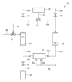
- BRIEF DESCRIPTION OF THE DRAWINGS It is a schematic block diagram which shows an example of the purification concentration apparatus based on 1st embodiment.
- BRIEF DESCRIPTION OF THE DRAWINGS It is a schematic block diagram which shows an example of the whole structure of the purification concentration apparatus based on 1st embodiment.
- the present disclosure relates to an apparatus for purifying and concentrating a liquid containing minute useful substances.
- the purification concentration device of the present disclosure has a first embodiment and a second embodiment.
- a first embodiment of the purification and concentration apparatus of the present disclosure will be described using the drawings.
- FIG. 1 is a schematic configuration diagram showing a purification and concentration apparatus 1 (hereinafter referred to as "purification and concentration apparatus 1") which is an example of a first embodiment of the present disclosure.
- the purification and concentration apparatus 1 of the present disclosure includes a raw material supply section 10 that supplies a raw material containing minute useful substances, a removal section 20 that removes impurities in the liquid, and a liquid supplied from the raw material supply section 10 or the removal section 20. Controls the timing of the flow of liquid from the purification and concentration section 30 that purifies and concentrates using a hollow fiber membrane, the raw material supply section 10 to the purification and concentration section 30, or the flow of liquid from the removal section 20 to the purification and concentration section 30. and a first control unit 110.
- the liquid in the raw material supply section 10 is supplied to the removal section 20 via a channel 41 or to the purification/concentration section 30 via a channel 43. Further, the liquid in the removal section 20 is supplied to the purification/concentration section 30 via a flow path 42 .
- the purification and concentration apparatus 1 of the present disclosure is capable of producing a liquid containing a minute useful substance in high purity and high concentration (a purified concentrate of a minute useful substance), and can more efficiently prepare the purified concentrate. It is also useful as a device that can purify and concentrate minute useful substances through automatic control. Note that in the present disclosure, the term "flow path" refers to a pipe through which a liquid flows.
- the raw material supply unit 10 stores a raw material liquid (hereinafter referred to as "raw material liquid") containing a minute useful substance.
- the raw material liquid in the raw material supply section 10 is supplied to the removal section 20 or the purification/concentration section 30 depending on its purity, that is, the concentration of impurities in the raw material liquid.
- the concentration of impurities in the raw material liquid is high, the raw material liquid is set to be supplied to the removal section 20, and when the concentration of impurities in the raw material liquid is low, the raw material liquid is supplied to the purification and concentration section 30. It can be set as follows.
- a flow path 41 for supplying the raw material liquid to the removal section 20 and a flow path 43 for supplying the raw material liquid to the purification/concentration section 30 are connected to the raw material supply section 10 .
- the raw material supply section 10 has a container that stores the raw material liquid.
- the container may be fixed to the purification/concentration device 1 or may be installed so as to be easily removable.
- the raw material supply unit 10 can include various equipment such as a fixing member for fixing the container.
- the shape and volume of the container for storing the raw material liquid are not particularly limited, and can be determined depending on the type of minute useful substance, the amount of the raw material liquid, etc.
- the volume of the container is 50 to 5,000 mL.
- the volume may be 200 to 2,000 mL.
- the removal unit 20 removes impurities in the raw material liquid supplied from the raw material supply unit 10 via the flow path 41 . According to this configuration, a purified concentrated solution of minute useful substances can be efficiently prepared.
- the liquid from which impurities have been removed in the removing section 20 will be referred to as a "crude purified liquid.”
- the removal section 20 shown in FIG. 2 is provided with a carrier column 21 for removing impurities in the raw material liquid.
- a carrier column 21 for removing impurities in the raw material liquid.
- One side of the carrier column 21 is connected to a flow path 41, and the other side is connected to a flow path 42 for supplying the crudely purified liquid to the purification/concentration section 30.
- a flow path (described later) for discharging liquid to a waste liquid tank (described later) may be connected to the flow path 42 from the carrier column 21.
- the removal unit 20 may be provided with a device including a container filled with an adsorbent that can adsorb and remove impurities in the raw material liquid.
- impurities in the raw material liquid can be adsorbed onto the adsorbent by actions such as stirring, vibration, and shaking, thereby removing and reducing the impurities.
- a rotator can also be used as such a device.
- the filler with adsorbed impurities can be removed by an optional filtration unit.
- the removal unit 20 shown in FIG. 3 includes a carrier column 21 and a first tank 23 that stores the crudely purified liquid treated in the carrier column 21.
- the first tank 23 is arranged in the flow path 42 . That is, the flow path 42 is arranged to be divided into a flow path 42A located on the carrier column 21 side and a flow path 42B located on the purification/concentration section side with the first tank 23 in between.
- the crude purified liquid is stored in the first tank 23 from the carrier column 21 via the channel 42A, and the crude purified liquid stored in the first tank 23 is supplied to the purification/concentration section 30 via the channel 42B.
- a three-way valve 77 is provided in the flow path 42B.
- the first control unit 110 opens the three-way valve 77 in the flow path 42B to the purification and concentration unit 30 side, depending on the processing status of the crude liquid in the purification and concentration unit 30, and controls the crude liquid in the first tank 23. is supplied to the purification and concentration section 30.
- the purification and concentration section 30 since the crude purified liquid can be temporarily stored in the first tank 23 and then supplied to the purification/concentration section 30, the impurity removal process in the removal section 20 and the purification/concentration process in the purification/concentration section 30 can be performed in parallel. You can do it by doing this. As a result, purification and concentration processing can be performed efficiently.
- the configuration of the removing section 20 shown in FIGS. 4 to 6 will be described later.
- the carrier column 21 is filled with a material capable of removing impurities other than minute useful substances in the raw material liquid.
- the material is an adsorbent that can adsorb and remove impurities in the raw material liquid.
- the adsorbent is preferably a porous particulate material that can adsorb and retain the impurities.
- the porous particulate material refers to a particulate material having a large number of pores on its surface and inside, and porous particulate materials of polymers and porous particulate materials of inorganic materials can be used.
- the porous particulate matter is is preferably positively charged.
- These porous particulate materials can be used alone or in combination with a plurality of materials having different adsorption performance. Multiple porous granules with different adsorption performance include those with different pore diameters, porous granules with different specific surface areas, porous granules with different average particle diameters, and porous granules with different average particle diameters.
- Examples include those having different types of constituent base materials, and those having different types and densities of functional groups present on the inner surface of the pores of the porous particles.
- Examples of such porous particles include cellulose, agarose, starch, amylose, dextran, pullulan, polysaccharides such as glucomannan, polyacrylic acid or its derivatives, polyvinyl alcohol, nylon, polysulfone, polyacrylic nitrile,
- Examples include those based on synthetic polymers such as polyethylene, polypropylene, and polystyrene, glass, porous glass, silica gel, hydroxyapatite, and the like. These may be used alone or in combination of two or more. It may also be a mixed mode support with ion exchange and size exclusion, preferably a mixed mode support with cation exchange and size exclusion.
- the porous particles can be selected from those having an average pore diameter in the range of 0.1 to 1,000 nm depending on the type of impurities contained in the raw material liquid. Note that the average pore diameter can be measured by mercury porosimetry or reverse size exclusion chromatography. Further, the porous particles may be selected from those having an average particle diameter in the range of 1 to 1,000 ⁇ m depending on the type of impurities contained in the raw material liquid. The average particle diameter can be measured by a laser diffraction scattering method.
- the carrier column 21 May include columns.
- the term "antibody column” refers to a column filled with a carrier on which antibodies that can bind to antigens (impurities) are immobilized.
- an antibody column filled with a carrier immobilized with an antibody capable of binding (adsorbing) impurities other than the biological substance can be employed. Note that since the raw material solution containing the aforementioned biomolecules as minute useful substances often contains multiple types of impurities, multiple antibody columns may be used depending on the types of impurities.
- a module formed by combining a plurality of carrier columns (column module) can also be employed.
- column modules the types of adsorbents contained in each carrier column may be the same or different.
- the inner diameter and length of the carrier columns may be the same or different.
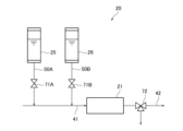
- the removal unit 20 shown in FIG. 4 includes a sixth tank 25 (cleaning liquid storage tank) that stores a cleaning liquid for cleaning the carrier column 21, and a seventh tank that stores an equilibration liquid for equilibrating the carrier column 21. 26 (equilibration liquid storage tank).
- the sixth tank 25 is configured to be able to supply cleaning liquid to the flow path 41 via the flow path 50A.
- the seventh tank 26 is configured to be able to supply the equilibration liquid to the flow path 41 via the flow path 50B.
- On-off valves 71A and 71B are arranged in the flow paths 50A and 50B.
- a three-way valve 72 is provided in the channel 42 that supplies the crudely purified liquid from the carrier column 21 to the purification/concentration section 30 .
- the cleaning and equilibration processing of the carrier column 21 is performed by opening the on-off valves 71A and 71B provided in the flow paths 50A and 50B, and supplying the cleaning liquid and the equilibration liquid from the sixth tank 25 and the seventh tank 26 to the carrier column 21. This can be done by doing this. It is preferable that the cleaning liquid and equilibration liquid after treating the carrier column 21 be discharged from a three-way valve 72 provided in the flow path 42 to a waste liquid tank (described later).
- the cleaning liquid for cleaning the carrier column 21 for example, a sodium chloride aqueous solution, hydrochloric acid, citric acid, a sodium hypochlorite aqueous solution, a sodium hydroxide aqueous solution, etc. can be adopted. From the viewpoint of safety, it is preferable to use an aqueous sodium chloride solution.
- a sodium chloride aqueous solution hydrochloric acid, citric acid, a sodium hypochlorite aqueous solution, a sodium hydroxide aqueous solution, etc.
- the equilibration solution for example, physiological saline, phosphate buffer (PBS), Tris-HCl buffer, sodium citrate buffer, citrate phosphate buffer, acetate buffer, borate buffer, etc. can be used.
- PBS phosphate buffer
- Tris-HCl buffer sodium citrate buffer
- citrate phosphate buffer acetate buffer
- borate buffer borate buffer
- the materials of the sixth tank 25 and the seventh tank 26 that store the cleaning liquid and the equilibration liquid are not particularly limited, and may have the same configuration as the second tank 31 and the third tank 32, which will be described later, for example. It is preferable that the sixth tank 25 and the seventh tank 26 have transparency so that the amount of liquid stored in the tank can be easily checked visually.
- the removal unit 20 shown in FIG. 5 includes a filtration member that removes impurities from the liquid before supplying the liquid to the carrier column 21.
- the removing section 20 shown in FIG. 5 has a configuration in which a filtering member 22 is interposed in a flow path 41.
- the raw material liquid filtered by the filtering member 22 is supplied to the carrier column 21 from a channel 41A of the channel 41 located on the carrier column 21 side with the filtering member 22 interposed therebetween.
- the raw material liquid that has been pretreated with the filtration member 22 can be supplied to the carrier column 21 .
- the raw material liquid treated with the filtration member 22 will be referred to as a "pretreatment liquid.”
- the removal section 20 in FIG. 5 has a configuration including a filtration member 22 and a carrier column 21, it can also be configured to include only the filtration member 22.
- the removal unit 20 shown in FIG. 6 includes a tank 24 (pretreatment liquid storage tank) that stores the pretreatment liquid from the filtration member 22.
- the pretreatment liquid from the filter member 22 is stored in the tank 24 via the flow path 41C.
- the pretreatment liquid stored in the tank 24 is supplied to the carrier column 21 via the flow path 41D.
- the first control unit 110 (not shown) opens the on-off valve 73 in the flow path 41D according to the progress of the impurity removal process in the carrier column 21, and transfers the pretreatment liquid in the tank 24 to the carrier column 21. Can be supplied.
- the pretreatment liquid can be temporarily stored in the tank 24 and then supplied to the carrier column 21, the filtration process in the filtration member 22 and the impurity removal process in the carrier column 21 can be performed in parallel. This is preferable because it allows for efficient purification and concentration treatment.
- the filter member 22 is arranged at the lower part of the raw material supply section 10. According to this configuration, since the supply of the raw material liquid from the raw material supply section 10 to the filtration member 22 proceeds due to the weight of the raw material liquid, the liquid sending member for supplying the raw material liquid from the raw material supply section 10 to the filtration member 22 (pumps, etc.) can be omitted. Therefore, it is preferable because it allows a more compact purification and concentration apparatus.
- the filtration member 22 is a member that filters the raw material liquid.
- the filtration member 22 is preferably a filtration filter including a microfiltration membrane (microfiltration membrane module).
- a microfiltration membrane microfiltration membrane module
- the average pore diameter of the microfiltration membrane is 0.10 to 0. .50 ⁇ m is preferable, and 0.15 to 0.30 ⁇ m is more preferable.
- the material for the microfiltration membrane polyether sulfone, polyvinylidene fluoride, etc. are preferable.
- commercially available products made of these materials can be used as the microfiltration membrane.
- FIG. 16 is a basic flowchart when purification and concentration processing is performed using the purification and concentration apparatus 1 shown in FIG. 13. An example of liquid distribution control in each control section is shown in the flowchart of FIG.
- the first control section 110 can supply the raw material liquid to the removal section 20 or the purification/concentration section 30 based on the result set by the impurity concentration of the raw material liquid in the raw material supply section 10 .
- the impurity concentration of the raw material liquid is high, the raw material liquid in the raw material supply section 10 is set to be supplied to the removal section 20.
- the first control unit 110 opens the three-way valve 82 disposed at the bottom of the container 11 in FIG.
- the pretreatment liquid is supplied to the tank 24.
- the first control unit 110 can supply the liquid from the tank 24 to the carrier column 21 until the amount of the crude purified liquid in the first tank 23 (crude purified liquid storage tank) reaches a set value.
- the pretreatment liquid can be supplied to the carrier column 21 by opening the on-off valve 73 provided at the bottom of the tank 24 .
- the first control unit 110 can also confirm the amount of liquid in the second tank 31 and the third tank 32.
- the first control unit 110 controls the liquid level in the second tank 31 and the third tank 32 to be a preset liquid level based on liquid level monitoring by tank liquid level monitoring devices 35 and 36 and/or a camera, which will be described later. If it is determined that there is, the three-way valve 77 connected to the flow path 42B can be opened toward the second tank 31 side, and the crude purified liquid in the first tank 23 can be supplied to the second tank 31.
- the flow path 42B connected to the first tank 23 in FIG. 13 is provided with a level sensor (not shown) that determines the amount of liquid in the tank.
- the first control unit 110 can determine whether or not the crude purified liquid remains in the first tank 23 based on the information from the level sensor.
- the first control unit 110 opens the on-off valve 73 and supplies the pretreated liquid in the tank 24 to the carrier column 21 again. can.
- the carrier column 21 can be washed and equilibrated every time one batch of processing is completed.
- the purification and concentration section 30 purifies and concentrates the liquid supplied from the raw material supply section 10 or the removal section 20 using a hollow fiber membrane. Since the hollow fiber membrane is used for purification and concentration, it is possible to prepare a liquid containing minute useful substances with high purity and high concentration.
- the material of the hollow fiber membrane of the present disclosure can be appropriately designed depending on the intended use of the present disclosure, the properties of the liquid containing minute useful substances, and the like. Specifically, organic polymers such as polyvinylidene fluoride (PVDF), polyethersulfone (PES), polysulfone (PSf), polyolefin (PE, PP, PTFE, etc.), polyamide, polyacrylonitrile, cellulose acetate (CA), etc. system materials and their modified products can be applied. Furthermore, a composite hollow fiber membrane consisting of a plurality of components selected from the above can also be applied.
- PVDF polyvinylidene fluoride
- PES polyethersulfone
- PSf polysulfone
- PE polyolefin
- CA polyacrylonitrile
- CA cellulose acetate
- the minute useful substance is a biomolecule such as an exosome
- a hollow fiber membrane made of cellulose acetate (CA) that is, it is preferably made of a resin material containing cellulose acetate).
- CA cellulose acetate
- the surface charge of the biomolecule is a weak negative charge, and the cellulose acetate film is also weakly negative, so the biomolecule and the cellulose acetate film do not attract each other with strong Coulomb force, and the circulation linear velocity can be adjusted appropriately. For example, by controlling the shear force of cross-flow filtration, it becomes easier to function.
- minute useful substances deposited on the membrane surface of the hollow fiber membrane can be more efficiently recovered by the method described below.
- the material of the hollow fiber membrane of the present disclosure can be appropriately designed depending on the purpose of use of the present disclosure and the properties of the raw material liquid containing minute useful substances.
- the surface of the hollow fiber membrane may be coated with an appropriate substance to improve its fouling resistance.
- the coating treatment can be carried out, for example, by a method similar to the method of bonding a cationic polymer to the surface of a hollow fiber membrane made of sulfonated polyether sulfone and polyether sulfone, which is described in Japanese Patent No. 6,081,290.
- a hollow fiber membrane is immersed in an aqueous solution (aqueous dispersion) of a coating material, or a method in which an aqueous solution (aqueous dispersion) of a coating material is passed through a hollow fiber membrane in the state of a hollow fiber membrane or a hollow fiber membrane module.
- a method can be used in which the coating material is adsorbed and bonded to the surface of the hollow fiber membrane by liquid washing, and then the coating material merely deposited on the thin layer of the coating material is removed by washing with water.
- coating a certain kind of biomolecule on a hollow fiber membrane made of cellulose acetate can improve the purification concentration efficiency and extracellular vesicles. This may be preferable in terms of increasing the recovery rate of minute useful substances such as vesicles.
- a hollow fiber membrane module made of cellulose acetate (molecular weight cut off: 300,000, membrane area: 0.062 m 2 )
- 200 mL of a 1.3 mg/mL skim milk powder solution dissolved in phosphate buffer (PBS) is added.
- the liquid was passed through the membrane for 10 minutes at a flow rate of /min, and a coating treatment was applied to the surface of the hollow fiber membrane to adsorb and bond biomolecules such as casein in skim milk powder to the surface of the hollow fiber membrane as a thin layer.
- a membrane can be used that has been washed with 250 mL of phosphate buffer solution (PBS) to remove excess components.
- PBS phosphate buffer solution
- a type of biomolecule different from the useful minute substance is attached to at least a partial region of the hollow fiber membrane. It is more preferable that the biomolecule is attached to half or more of the surface of the hollow fiber membrane, and it is preferable that the biomolecule is attached to the entire surface of the hollow fiber membrane.
- a layer containing a different type of biomolecule from the minute useful substance is preferably formed on at least a portion of the surface of the hollow fiber membrane. The term "layer containing biomolecules" means that a substance containing biomolecules is adhered to at least a part of the hollow fiber membrane over a certain extent.
- the layer containing biomolecules is preferably formed over half or more of the surface of the hollow fiber membrane, and more preferably over the entire surface. In one embodiment, it is preferable that at least a portion of the surface of the hollow fiber membrane is coated with a different type of biomolecule from the minute useful substance.
- Biomolecules of a different type than minute useful substances include those obtained from animal cell tissues such as blood, milk, and cartilage, and other biological cell tissues.
- animal cell tissues such as blood, milk, and cartilage
- a typical example is biological molecules contained in skim milk and skim milk powder.
- Molecules eg, casein
- biomolecules contained in serum eg, serum globulin, serum albumin
- gelatin eg, fish gelatin
- the average inner diameter of the hollow fiber membrane of the present disclosure can be appropriately designed depending on the intended use of the present disclosure, the properties of the liquid containing minute useful substances, and the like.
- hollow fiber membranes having an average inner diameter of 0.2 mm to 1.4 mm can be employed.
- hollow fiber membranes having an average inner diameter of 0.2 mm to 2.0 mm can be employed.
- the "average inner diameter of a hollow fiber membrane" in the present disclosure refers to the diameter of the smallest circle that is inscribed in the hollow part of one hollow fiber membrane when cut at an arbitrary plane perpendicular to the longitudinal direction. This is the value calculated from In the present disclosure, the diameters are measured at arbitrary 10 to 100 points on the cut surface, and the average value is defined as the "average inner diameter.”
- the hollow fiber membrane of the present disclosure may have an average outer diameter of 0.3 mm to 2.0 mm.
- the average outer diameter may be 0.3 mm to 1.4 mm.
- the average outer diameter may be 1.5 mm to 2.0 mm.
- the "average outer diameter of a hollow fiber membrane" is a value calculated from the diameter of the smallest circle that includes the outer edge of the cut surface of a hollow fiber membrane cut in the same manner as the average inner diameter of the hollow fiber membrane described above. be. In the present disclosure, the diameters are measured at arbitrary 10 to 100 locations on the cut surface, and the average value is defined as the "average outer diameter.”
- the hollow fiber membrane The average inner diameter of may be 0.6 mm to 1.4 mm. Further, the average inner diameter may be adjusted depending on the viscosity of the liquid containing the minute useful substance during operation.
- the liquid viscosity is high (for example, when the liquid viscosity at a liquid temperature of 20°C and a shear rate of 25 s -1 is 10 to 30 mPa ⁇ s)
- a large diameter hollow fiber membrane with an average inner diameter of 1.0 mm to 1.4 mm is used.
- the average inner diameter is 0. It is preferable to use a hollow fiber membrane of 6 mm to 1.0 mm. Note that when the average inner diameter of the hollow fiber membrane increases, the effective membrane area tends to decrease when the hollow fiber membrane is used as a hollow fiber membrane module. Therefore, from the viewpoint of easily suppressing a decrease in the effective membrane area when used as a hollow fiber membrane module, it is preferable to use a hollow fiber membrane having an average inner diameter of 0.2 mm to 1.0 mm.
- the molecular weight cutoff of the hollow fiber membrane of the present disclosure can be appropriately designed depending on the purpose of use of the present disclosure, the properties of the raw material liquid containing minute useful substances, and the like. In one embodiment, the molecular weight cutoff may be from 5,000 to 3,000,000, or from 10,000 to 1,000,000.
- a hollow fiber membrane with a molecular weight cut-off slightly lower than the molecular weight of the protein for example, a hollow fiber membrane with a molecular weight cut-off about 10 to 50% lower than the molecular weight of the protein is used.
- the molecular weight cutoff of the hollow fiber membrane is preferably 50,000 to 1,000,000, more preferably 70,000 to 800,000, and more preferably 100,000 to 500,000. It is more preferable that
- the ⁇ -globulin permeability of the hollow fiber membrane module of the present disclosure is preferably 5 to 90%, more preferably 10 to 80%, from the viewpoint of purification and concentration efficiency. preferable.
- the method for measuring the transmittance of impurities in a liquid containing minute useful substances, including the aforementioned ⁇ -globulin is not particularly limited, and conventionally known methods can be employed. Specifically, a method of measuring the transmittance of a standard substance having a molecular structure similar to that of the impurity and a similar molecular weight can be adopted.
- a hollow fiber membrane module When measuring the transmittance, a hollow fiber membrane module may be used, or a single hollow fiber membrane used in the hollow fiber membrane module may be directly used. Furthermore, the permeability of the internal pressure type hollow fiber membrane module may be substituted with the permeability measured by applying pressure from the outside of the hollow fiber membrane to the inside of the hollow fiber membrane.
- the purification/concentration section 30 in the present disclosure may include a hollow fiber membrane module in which a plurality of the hollow fiber membranes are housed in a container having an inlet/outlet for liquid.
- the container also includes a first liquid inlet/outlet 33a and a second liquid inlet/outlet 33b for supplying liquid to the hollow fiber membrane, and a third liquid inlet/outlet 33b for discharging the liquid that has passed through the hollow fiber membrane. It has at least liquid inlets and outlets 33c and 33d.
- the number of hollow fiber membranes used in the hollow fiber membrane module of the present disclosure is not particularly limited. Depending on the purpose of use of the present disclosure and the weight of minute useful substances to be purified and concentrated, the number of membranes to be incorporated into the module can be appropriately designed to obtain the necessary effective membrane area.
- the hollow fiber membranes are bundled with an adhesive or the like and stored in the container.
- a liquid containing minute useful substances is supplied from the first liquid inlet/outlet 33a and/or the second liquid inlet/outlet 33b of the hollow fiber membrane module, one side of the hollow fiber membrane bundle in the container ( The liquid flows into the hollow fiber membrane bundle (inside or outside) and is purified and concentrated by the hollow fiber membrane bundle.
- the liquid that has permeated the hollow fiber membrane bundle flows out to the other side of the hollow fiber membrane bundle (outside or inside the hollow fiber membrane bundle) and is discharged from the third liquid inlets and outlets 33c and 33d.
- the liquid that remains inside or outside the hollow fiber membrane bundle without being permeated is discharged (recovered) from the hollow fiber membrane module through the first liquid inlet/outlet and/or the second liquid inlet/outlet.
- a liquid that has permeated through a hollow fiber membrane will be referred to as a "permeated liquid”
- a liquid that has not permeated the hollow fiber membrane and has remained in the hollow fiber membrane will be referred to as a "concentrated liquid.”
- concentrated liquid refers to all liquids that have been purified and concentrated using a hollow fiber membrane.
- a hollow fiber membrane module in which the liquid containing minute useful substances is supplied to the inside of the hollow fiber membrane bundle is an internal pressure type hollow fiber membrane module
- a hollow fiber membrane module in which the liquid containing minute useful substances is supplied to the outside of the hollow fiber membrane bundle is an external pressure type hollow fiber membrane module. It is a membrane module.
- an internal pressure type hollow fiber membrane module will be described as an embodiment of the hollow fiber membrane module in the present disclosure.
- FIG. 7 is a schematic cross-sectional view showing an example of an internal pressure type hollow fiber membrane module 33.
- a hollow fiber membrane bundle 60 in which a plurality of hollow fiber membranes are bundled is housed in a cylindrical container 61.
- the plurality of hollow fiber membranes are bundled together with a biocompatible sealing adhesive (for example, a polyurethane sealing adhesive, etc.) to form a hollow fiber membrane bundle 60, and are arranged in a cylindrical container 61. It is configured to be adhesively fixed at both ends in the longitudinal direction with adhesive layers 62a and 62b made of the sealing adhesive.
- a biocompatible sealing adhesive for example, a polyurethane sealing adhesive, etc.
- the cylindrical container 61 may be made of a material such as polycarbonate, poly(meth)acrylate, or polysulfone.
- both end surfaces 61a and 61b of the cylindrical container 61 are in a state where a plurality of hollow fiber membranes are opened.
- a first liquid inlet/outlet 33a and a second liquid inlet/outlet 33b are provided at both longitudinal ends of the hollow fiber membrane module 33.
- third liquid inlet/outlet ports 33c and 33d are provided on the longitudinal side surface of the hollow fiber membrane module 33. The liquid supplied from the first liquid inlet/outlet 33a and/or the second liquid inlet/outlet 33b is sent inside the hollow fiber membrane bundle 60 to be purified and concentrated.
- the permeated liquid that has permeated to the outside of the hollow fiber membrane bundle 60 is discharged from third liquid inlets and outlets 33c and 33d provided on the side surface of the cylindrical container 61.
- the third liquid inlet/outlet be provided at at least two places, an upper side of the cylindrical container 61 and a lower side of the cylindrical container 61 .
- the third liquid inlets and outlets 33c and 33d are provided only on one side surface of the hollow fiber membrane module 33, but the present invention is not limited to this.
- the third liquid ports 33c and 33d may be provided separately on one side surface and the other side surface.
- FIG. 7 illustrates an internal pressure type hollow fiber membrane module
- the hollow fiber membrane module of the present disclosure may be an external pressure type as described above.
- an external pressure type it is necessary to appropriately design the location and installation method of the first to third liquid inlets and outlets.
- the filling rate in the hollow fiber membrane module of the present disclosure is preferably 5 to 55%, more preferably 20 to 55%, even more preferably 25 to 55%.
- the filling rate refers to the percentage of the total cross-sectional area of the outer diameter portion of the hollow fiber membrane bundle to the cross-sectional area of the hollow fiber membrane module, generally in the transverse direction of the cylindrical container.
- the filling rate is 5 to 55%, it is possible to more efficiently recover minute useful substances deposited on the membrane surface of the hollow fiber membrane while optimizing the size of the hollow fiber membrane module.
- the purification/concentration section 30 of the present disclosure includes a hollow fiber membrane module 33
- a hollow fiber membrane module 33 will be described using the drawings.
- the purification and concentration apparatus 1 of the present disclosure may include safety devices such as valves, automatic valves, check valves, orifices, flow meters, pressure gauges, level gauges, rupture discs, etc. that are omitted in the schematic configuration diagram. There is.
- the purification and concentration section 30 shown in FIG. 8 includes a second tank 31 and a third tank 32, a hollow fiber membrane module 33 connected to the second tank 31 and the third tank 32, and a and a pressurizing device 34 for pressurizing.
- the pressurizing device 34 is connected to a three-way valve 76 via a gas supply path 52.
- the second tank 31 is a tank that stores the liquid supplied from the raw material supply section 10 or the removal section 20, that is, the raw material liquid or the crudely purified liquid, and is connected to the first liquid inlet/outlet 33a of the hollow fiber membrane module 33. They are connected via a path 51A.
- the third tank 32 is a tank for storing a raw material liquid or a crudely purified liquid, and is connected to the second liquid inlet/outlet 33b of the hollow fiber membrane module 33 via a flow path 51B. has been done.
- the upper parts of the second tank 31 and the third tank 32 are connected to a pressurizing device 34.
- the second control unit 120 (not shown) selectively pressurizes either the second tank 31 or the third tank 32 by operating the pressurizing device 34 and switching the three-way valve 76.
- the raw material liquid or the crudely purified liquid in the second tank 31 or the third tank 32 is controlled to be alternately (selectively) supplied to the hollow fiber membrane module 33.
- the liquid discharged from the second tank 31 or the third tank 32 is purified and concentrated in the hollow fiber membrane module 33, and then sent to the other tank.
- the liquid stored in the second tank 31 and before the purification and concentration process is completed will be referred to as "second stored liquid”
- the liquid stored in the third tank 32 and purified The liquid before the concentration process is completed is referred to as the "third stored liquid.”
- the flow paths 42 and 43 are connected to the second tank 31 in FIG. 8, the flow paths 42 and 43 may be connected to the third tank 32. Note that details of the second control section 120 will be described later.
- the pressurizing device 34 of the present disclosure supplies gas from the gas supply source into the second tank 31 and the third tank 32.
- Gas for pressurization is supplied to the second tank 31 or the second tank 31 or the gas supply path 52B equipped with a pressure gauge (not shown) by switching the three-way valve 76 by the second control unit 120 (not shown). It is supplied to the third tank 32.
- the gas can be selected from inert gases such as nitrogen, argon, and helium, carbon dioxide, and filtered air.
- the second control unit 120 When pressurizing the second tank 31 with the pressurizing device 34, the second control unit 120 (not shown) supplies gas from a gas supply source (not shown) to the gas supply path 52, and closes the three-way valve 76. The gas is switched and sent to the gas supply path 52A. At this time, the on-off valve 74 of the gas vent path 53A and the three-way valve 77 connecting the channels 42 and 43 are closed, and the on-off valve 75 of the gas vent path 53B is opened. On the other hand, when pressurizing the third tank 32 with the pressurizing device 34, the second control unit 120 supplies gas from a gas supply source (not shown) to the gas supply path 52, and switches the three-way valve 76 to It is sent to the supply path 52B.
- the second tank 31 and the third tank 32 have transparency so that the liquid level positions of the second and third stored liquids can be observed visually or with a camera described later. It is preferable that you do so. Further, from the viewpoint of preventing the second stored liquid or the third stored liquid from adhering to and remaining on the inner wall surface of the tank, it is more preferable to use a water-repellent material.
- the second tank 31 and the third tank 32 are preferably made of a material containing polyacrylonitrile; poly(meth)acrylate such as poly(meth)acrylic acid ester; polycarbonate; fluororesin, etc. .
- the material of the second tank 31 and the third tank 32 is opaque.
- Tanks made of suitable materials such as metal or fiber-reinforced resin can be used.
- the second stored liquid enters the hollow fiber membrane module 33 from the first liquid inlet/outlet 33a via the flow path 51A, and is purified and concentrated by the hollow fiber membrane bundle 60.
- the liquid is discharged from the second liquid inlet/outlet 33b and sent to the third tank 32.
- the second stored liquid is purified and concentrated by tangential flow filtration in which the liquid flows parallel to the membrane surface in the longitudinal direction of the hollow fiber membrane bundle 60.
- the permeated liquid that has passed through the hollow fiber membrane bundle 60 is discharged from a flow path 54 connected to the third liquid inlet/outlet 33c, 33d of the hollow fiber membrane module 33 to a waste liquid tank (described later).
- the third stored liquid enters the hollow fiber membrane module 33 from the second liquid inlet/outlet 33b via the flow path 51B, is purified and concentrated by the hollow fiber membrane bundle 60, and then becomes the first liquid.
- the liquid is discharged from the inlet/outlet 33a and sent to the second tank 31.
- the third stored liquid is purified and concentrated by tangential flow filtration in which the liquid flows parallel to the membrane surface in the longitudinal direction of the hollow fiber membrane bundle 60.
- the second control unit 120 sets the amounts of the second and third stored liquids, and controls the pressurizing device 34 and the on-off valve so that the second and third stored liquids reach the set values.
- the second tank 31 or the third tank 32 can be pressurized alternately.
- the purification/concentration section 30 in FIG. 8 can be configured to include a device for monitoring the liquid amount in the second tank 31 and the third tank 32. According to this configuration, since the amount of liquid in the second tank 31 and the third tank 32 can be grasped, alternate tangential flow filtration can be performed more efficiently.
- the refining and concentrating unit 30 shown in FIG. 9 has the same configuration as the refining and concentrating unit 30 shown in FIG.
- the tank is equipped with tank liquid amount monitoring devices 35 and 36, respectively.
- the in-tank liquid level monitoring devices 35 and 36 irradiate the liquid entrances and exits of the second tank 31 and the third tank 32 with light using optical sensors, detect the light transmittance at the liquid entrances and exits, and measure the transmittance.
- the system is configured to monitor the amount of liquid in the tank based on changes in the amount of fluid in the tank.
- the second control unit 120 (not shown) determines the liquid volumes of the second and third stored liquids in the second tank 31 and the third tank 32 using the tank liquid level monitoring devices 35 and 36, The tank to be pressurized by the pressurizing device 34 is determined.
- the tank liquid level monitoring devices 35 and 36 of the present disclosure include an optical sensor.
- the optical sensor includes a light emitting element and a light receiving element, and the light emitting element emits light toward the liquid entrance/exit at the bottom of the tank, and the light receiving element detects the intensity (transmittance) of the transmitted light.
- the part at the bottom of the tank that is illuminated by light at the liquid entrance and exit is made of a transparent material.
- the detected transmittance is further transmitted to the detection section.
- the second control unit 120 changes the tank to be pressurized by the pressurization device 34.
- the relationship between the tank liquid level monitoring device and the second control section will be explained in more detail.
- the second tank 31 is pressurized by the pressurizing device 34 and the second stored liquid is supplied toward the third tank 32
- the pressure increases.
- the gas supplied from the pressure device 34 is discharged from the liquid inlet/outlet of the second tank 31, and the light transmittance within the liquid inlet/outlet changes.
- the second control unit 120 (not shown) switches the three-way valve 76 to move the tank pressurized by the pressurizing device 34 from the second tank 31 to the third tank. Change to tank 32.
- the second control unit 120 switches the three-way valve 76 and applies pressure with the pressurizing device 34.
- the tank to be pressurized is changed from the third tank 32 to the second tank 31.
- the tank liquid level monitoring devices 35 and 36 may be fiber sensors. In this way, the second control unit 120 can control the liquids in the second tank 31 and the third tank 32 to be alternately supplied to the hollow fiber membrane module.
- the amount of liquid in the tank may be monitored based on images from a camera placed in the purification/concentration section 30. That is, the purification/concentration unit 30 includes a camera that monitors the liquid level positions in the second tank 31 and the third tank 32, and the second control unit 120 controls the second tank 31 and the third tank output from the camera. The amount of liquid in the tank may be determined from information on the liquid level position in the tank 32, and the tank to be pressurized by the pressurizing device 34 may be determined. Specifically, the purification and concentration unit 30 is equipped with a camera at a position where the liquid level of the second tank 31 and the third tank 32 can be observed, and the image of the liquid level position output from the camera is sent to the detection unit. be done.
- the detection unit determines the second tank 31 and the amount of liquid in the second tank 31 from the information on the liquid level position. For example, when the detection unit determines that the amount of the second stored liquid in the second tank 31 has become a preset amount or less based on the information on the liquid level position of the camera, the second control unit 120 controls the three-way valve 76. By switching, the tank pressurized by the pressurizing device 34 is changed from the second tank 31 to the third tank 32. Similarly, when the detection unit determines that the amount of the third stored liquid in the third tank 32 has become equal to or less than the preset amount, the second control unit 120 switches the three-way valve 76 and pressurizes the pressurizing device 34. The tank to be pressurized is changed from the third tank 32 to the second tank 31.
- the second control unit 120 can operate an on-off valve or a pressurizing device to mainly circulate the liquid (roughly purified liquid or raw material liquid) between the second tank 31 and the third tank 32. . Further, the second control unit 120 determines the amount of liquid in the second tank 31 and the third tank 32 based on information from the tank liquid amount monitoring devices 35, 36 and/or the camera, and controls the amount of liquid in the tank. It can be distributed. Furthermore, the second control unit 120 can also set the amount of liquid in the second tank 31 and/or the third tank 32. An example of a method for setting the amount of liquid in the tank (setting of the managed liquid level position C) will be described later.
- the purification/concentration section 30 in FIG. 10 includes a cleaning tank that supplies a diluent to the hollow fiber membrane module 33 and cleans the plurality of hollow fiber membranes in the hollow fiber membrane bundle 60.
- the purification/concentration section 30 shown in FIG. 10 includes a fourth tank 80 connected to a channel 55A that stores the diluted liquid and supplies the diluted liquid to the third liquid inlet/outlet ports 33c and 33d of the hollow fiber membrane module 33. , and a third control unit 130 (not shown) that controls the timing of supplying the diluted liquid in the fourth tank 80 to the third liquid inlet/outlet ports 33c and 33d of the hollow fiber membrane module 33.
- the fourth tank 80 is connected to a flow path 55B that directly supplies the diluent in the tank to the third tank 32 (or second tank 31).
- the third control unit 130 controls the flow of the diluent in the fourth tank 80.
- An example of the determination in liquid distribution control by the third control unit 130 is shown in the flowchart of FIG. 16.
- the third control unit 130 can supply the diluted liquid from the fourth tank 80 to either the third tank 32 or the hollow fiber membrane module 33 during liquid purification and concentration processing.
- supplying the diluted liquid to the third tank 32 will be referred to as a "dilution process”
- supplying the diluted liquid to the hollow fiber membrane module 33 will be referred to as a "backwashing process”.
- diluent As the diluent, depending on the purpose of the present disclosure and the type of minute useful substance, for example, pure water; filtered water such as tap water, ground water, seawater, or river water; various aqueous solutions, etc. can be used. When the minute useful substance is an exosome, physiological saline, medical or biochemical buffers are preferred.
- the buffer for example, phosphate buffer (PBS), Tris-HCl buffer, sodium citrate buffer, citrate phosphate buffer, acetate buffer, borate buffer, etc. can be used.
- the diluent preferably does not contain impurities depending on the purpose of the present disclosure, but if it is difficult to obtain a diluent that does not contain impurities, it is preferable to use one with a low impurity concentration (for example, one with an impurity concentration of less than 500 ppm). ) can be used.
- the diluted liquid is such that the amount (B) (B/A) of the concentrated liquid in the second tank 31 (or third tank 32) is 1/1/1 of the amount (A) of the raw material liquid containing minute useful substances.
- concentration 2 to 1/200, it can be supplied to the concentrated liquid in the second tank 31 (or third tank 32).
- the amount (B) of the concentrated liquid may be equal to the amount of liquid at the managed liquid level position C set by the method described later.
- the third control unit 130 can be processed.
- the third control unit 130 can determine that the crudely purified liquid or the raw material liquid has been supplied into the second tank 31 based on the liquid level position information from the tank liquid amount monitoring device 35 and/or the camera. In one embodiment, the third control unit 130 performs concentration and purification by performing alternate tangential flow filtration until the volume of the crude purified liquid reaches 1/2 to 1/200, and then reaches the set liquid volume. The dilution process (or backwashing process) can be performed up to the point where the diluted solution can be supplied. When performing the dilution process, the third control unit 130 opens the three-way valve 77A to the channel 55B side and supplies the diluent in the fourth tank 80 to the third tank 32.
- the third control unit 130 controls when the total amount of liquid in the second tank 31 and the third tank 32 becomes equal to or less than a preset liquid amount (for example, equal to or less than a managed liquid level position C set by a method described later). If it is determined that this is the case, backwashing can be performed. When performing backwash processing, the third control unit 130 opens the three-way valve 77A to the flow path 55A side. The diluted liquid in the fourth tank 80 is supplied into the module from the third liquid inlet/outlet ports 33c and 33d of the hollow fiber membrane module 33 via the flow path 55A. Thereafter, the diluted liquid flows from the permeated liquid side to the concentrated liquid side of the hollow fiber membrane bundle 60.
- a preset liquid amount for example, equal to or less than a managed liquid level position C set by a method described later.
- the diluent supplied into the module from the third liquid inlets and outlets 33c and 33d flows from the outside of the hollow fiber membrane bundle 60 toward the inside.
- minute useful substances deposited on the membrane surface of the hollow fiber membrane are removed from the first liquid inlet/outlet 33a and/or the second liquid inlet/outlet 33b to the second tank 31 and/or the membrane surface inside the hollow fiber membrane.
- it can be collected in the third tank 32.
- minute useful substances and impurities deposited on the surface of the hollow fiber membrane are removed, and the liquid permeation rate is restored to almost its original value.
- impurities are uniformly dispersed and the removal efficiency is increased. As a result, the efficiency of liquid purification and concentration can be further improved.
- flushing with a cleaning liquid is performed in advance.
- An operation of replacing the permeated liquid remaining in the hollow fiber membrane module with a cleaning liquid (diluent) can be optionally performed.
- the amount of cleaning liquid (diluent) used is preferably 1 to 8 times, more preferably 2 to 6 times, the volume of the permeate remaining in the hollow fiber membrane module.
- the amount of remaining impurity protein will be lower than when no flushing operation is performed. may be reduced by more than half.
- the permeate remaining in the hollow fiber membrane module is removed by using either the third liquid inlet/outlet 33c or 33d in FIG. (diluent) can be performed. Since the hollow fiber membrane has resistance to liquid passage, if the diluent is supplied from either the third liquid inlet/outlet 33c or 33d, leakage to the membrane side is minimized and the hollow fiber membrane module The permeate remaining in 33 can be replaced with diluent.
- an on-off valve (not shown) is provided on the flow path near the outlet of the first liquid inlet/outlet 33a and the second liquid inlet/outlet 33b, and by closing the on-off valve, the first liquid inlet/outlet 33a and the second liquid inlet/outlet 33b are closed. It is also possible to stop the flow of the liquid through the second liquid inlet/outlet 33b. In this state, by supplying the diluent from one of the third liquid ports 33c and 33d, the diluted liquid is discharged from the other third liquid port 33c or 33d. Thereby, the permeate remaining in the hollow fiber membrane module 33 can be replaced with the diluent.
- the timing of the flushing process is controlled by the third control section.
- the third control section controls the second tank 31 and the second liquid inlet/outlet 33b.
- a valve is installed near the first liquid inlet/outlet 33a and the second liquid inlet/outlet 33b. With the installed on-off valve closed to stop the flow of the liquid, the diluted liquid in the fourth tank 80 is transferred to at least two third liquid inlets and outlets 33c and 33d of the hollow fiber membrane module 33.
- the on-off valve 78 provided in the flow path 54 connected to the waste liquid tank is open. Thereafter, opening/closing valves installed near the first liquid inlet/outlet 33a and the second liquid inlet/outlet 33b are opened to allow flow through the first liquid inlet/outlet 33a and the second liquid inlet/outlet 33b. backwashing by supplying the diluted liquid in the fourth tank 80 from any one of the at least two third liquid inlets and outlets 33c and 33d of the hollow fiber membrane module 33. It can be carried out. At this time, the on-off valve 78 provided in the flow path 54 connected to the waste liquid tank is closed.
- the purification and concentration section 30 shown in FIG. 11 includes a recovery tank that recovers the concentrated liquid purified and concentrated by the hollow fiber membrane module 33.
- the purification and concentration section 30 in FIG. A fourth control section 140 (not shown) that controls recovery of the liquid in the tank 32 is provided.
- the fifth tank 81 may be connected to the second liquid inlet/outlet 33b of the hollow fiber membrane module 33.
- the channel 56 is connected to the hollow fiber membrane module 33 via the channel 51A.
- the on-off valve 79 is closed while the purification and concentration process by alternate tangential flow filtration is being performed in the second tank 31 and the third tank 32.
- the concentrated liquid in the second tank 31 and the third tank 32 can be collected into the fifth tank 81 by opening the on-off valve 79 and operating the pressurizing device 34 .
- the tank for collecting the concentrated liquid may be arranged outside the purification and concentration apparatus instead of inside the purification and concentration section 30.
- the fourth control unit 140 controls the timing of collecting the concentrated liquid in the second tank 31 and the third tank 32.
- An example of the determination made by the fourth control unit 140 in the liquid distribution control is shown in the flowchart of FIG. 16.
- the fourth control unit determines the amount of concentrated liquid in the second tank 31 and the third tank 32 using the tank liquid amount monitoring devices 35, 36 and/or the camera.
- the amount of the concentrated liquid may be determined from the managed liquid level position C, which will be described later.
- the fourth control unit 140 pressurizes the second tank 31 and the third tank 32 using the pressurizing device 34.
- the on-off valve 74 of the gas vent path 53A, the on-off valve 75 of the gas vent path 53B, the on-off valve 78, and the three-way valves 77 and 77A are closed, and the on-off valve 79 is opened.
- the The fourth control unit 140 stops the pressurizing device 34 and finishes collecting the concentrated liquid into the fifth tank 81.
- the fourth control unit 140 monitors the amount of concentrated liquid in the channel 56 with a fiber sensor (not shown) installed at the liquid inlet/outlet in the upper part of the fifth tank 81, and determines whether the liquid amount is If it is determined that the amount has become zero, collection of the concentrated liquid may be terminated.
- the concentrated liquid recovery operation inside the channel 56 can be manually operated by a person.
- the flow path 56 can be fixedly held using an air gripper or the like.
- FIG. 12 shows an example of the configuration of the purification and concentration apparatus according to the first embodiment.
- elements including a raw material supply section 10, a removal section 20, and a purification and concentration section 30 are arranged in a housing.
- the size of the housing is not particularly limited.
- the purification and concentration apparatus 1 includes a management section (not shown) that manages the cleanliness inside the housing. According to this configuration, the inside of the purification/concentration apparatus 1 can be kept clean, and contamination of the liquid containing minute useful substances can be prevented.
- a fan filter device 91 that supplies filtered air into the housing is arranged at the upper part (top) of the housing 100, and a UV lamp 92 is arranged inside the housing 100. These combinations can further improve the cleanliness inside the housing 100.
- the fan filter device 91 has a configuration that can supply filtered air into the housing.
- the fan filter device 91 can be a filter unit with a fan and a built-in pre-filter.
- a pre-filter a HEPA filter, ULPA filter, chemical filter, fiber activated carbon filter, etc. can be used depending on the cleanliness inside the housing 100.
- UV lamp The UV lamp 92 is not particularly limited as long as it can sterilize the inside of the housing 100 by irradiating UV (ultraviolet light). Furthermore, the number of UV lamps 92 disposed within the housing 100 is not particularly limited, and two or more UV lamps may be disposed depending on the cleanliness within the housing 100.
- the cleanliness inside the housing 100 can be improved by the above-mentioned management section.
- the cleanliness inside the housing 100 may be managed to be a cleanliness class 8 or lower as defined by ISO 14644-1:2015, and may be managed to be a cleanliness class 5 or lower as defined by ISO 14644-1:2015. may have been done.
- the minute useful substance is not particularly limited. In one embodiment, it may be a minute useful substance with an average particle size of less than 100 ⁇ m. In another embodiment, it may be a minute useful substance with an average molecular weight of 5,000 or more. Among these, all substances useful as pharmaceuticals, cosmetics, and health foods can be used. Specific examples of minute useful substances include proteins (e.g., heat shock proteins, cytoskeletal proteins, membrane transport proteins, transmembrane proteins, collagen, hyaluronic acid, chondroitin sulfate, etc.), hormones, cytokines, growth factors, and angiogenesis.
- proteins e.g., heat shock proteins, cytoskeletal proteins, membrane transport proteins, transmembrane proteins, collagen, hyaluronic acid, chondroitin sulfate, etc.
- hormones cytokines, growth factors, and angiogenesis.
- Living organisms such as factors, growth factors, enzymes, antibodies, plasma proteins, viruses (including virus-like particles), extracellular vesicles (e.g., exosomes, microvesicles, apoptotic bodies, etc.), yeast, yeast cells, and microalgae
- extracellular vesicles e.g., exosomes, microvesicles, apoptotic bodies, etc.
- yeast yeast cells
- microalgae examples include molecules, polysaccharides such as fucoidan, and the like.
- Other examples include specific microorganisms that are a type of biomolecule and are used in biofuels and the like.
- minute useful substances may be selected from extracellular vesicles, antibodies, viruses, proteins, enzymes, and nucleic acids.
- the manufacturing method according to the first embodiment of the present disclosure is a method of manufacturing the liquid in which the minute useful substance is purified and concentrated using the purification and concentration device 1, and the method includes converting the raw material liquid containing the minute useful substance into the liquid.
- the method includes supplying the liquid to a purification and concentration device to remove impurities in the liquid, and/or purifying and concentrating the liquid using a hollow fiber membrane.
- FIG. 13 is a configuration diagram showing an example of the overall configuration of the purification and concentration apparatus 1 of the present disclosure.
- the raw material supply section 10 has a structure in which a container 11 for storing a raw material liquid containing a minute useful substance is arranged.
- the three-way valve 82 opens, and the raw material liquid in the container 11 falls due to its own weight and is supplied to the flow path 59 by a pump (not shown) provided in the flow path 41A.
- the raw material liquid is supplied to the flow path 41 or the flow path 43 by operating the three-way valve 82.
- the first control section 110 supplies the raw material liquid to the removal section 20 or the purification/concentration section 30 based on information set based on the concentration of impurities in the raw material liquid.
- the first control unit 110 opens the three-way valve 82 to the channel 43 side, and sends the culture solution from the channel 43 to the purification/concentration section 30 .
- the raw material liquid supplied to the flow path 41 is pretreated by the filtration member 22 and then supplied to the tank 24 via the flow path 41C.
- the amount of liquid in the tank 24 can be controlled by monitoring the liquid level using a level sensor (not shown).
- the on-off valve 73 is opened, the pretreatment liquid in the tank 24 is supplied from the flow path 41D to the flow path 41A.
- the pretreatment liquid supplied to the carrier column 21 adsorbs and removes impurities in the liquid by the adsorbent in the carrier column 21 to become a crudely purified liquid, and then is supplied to the first tank 23 via the flow path 42A. Ru.
- the impurity removal treatment by the carrier column 21 may be to reduce the concentration of impurities in the raw material liquid or pretreatment liquid to 1,000 ppm or less, preferably to 500 ppm or less.
- the impurity removal process is repeated by washing and equilibrating the carrier column 21 that has reached adsorption saturation by processing one batch of raw material liquid, and then processing the next batch of raw material liquid. It's okay.
- the purification/concentration apparatus 1 in FIG. 13 has a configuration including a sixth tank 25 and a seventh tank 26.
- When cleaning and equilibrating the carrier column 21 that has reached adsorption saturation first open the on-off valve 71A (electromagnetic valve, etc.) and supply the cleaning liquid in the sixth tank 25 to the filtration member 22A via the flow path 50A. do. After the impurities in the cleaning liquid are removed by the filter member 22A, the cleaning liquid is supplied to the carrier column 21 from the flow path 41A.
- the cleaning liquid after cleaning the carrier column 21 can be discharged to the waste liquid tank by opening the three-way valve 72.
- the same filter member as the filter member 22 can be used as the filter member 22A.
- the on-off valve 71B (such as a solenoid valve) is opened to supply the equilibration liquid in the seventh tank 26 to the filtration member 22B.
- the equilibration liquid is supplied to the carrier column 21 from the flow path 41A.
- the equilibrated liquid after equilibrating the carrier column 21 can be discharged to the waste liquid tank by opening the three-way valve 72.
- the same member as the filter member 22 can be used for the filter member 22B.
- Washing and equilibration of the carrier column 21 can be arbitrarily set depending on the amount of raw material liquid treated with the carrier column 21.
- the carrier column 21 may be washed and equilibrated when a raw material solution of 5 to 100 times the capacity of the carrier column 21 is processed. For example, when processing 1,000 mL of raw material solution, the carrier column 21 can be washed and equilibrated every time 20 to 150 mL of the raw material solution is processed in the carrier column 21, and each time 50 to 100 mL is processed. , washing, and equilibration treatments can also be performed.
- the removal of impurities in the raw material liquid by the carrier column 21 and the purification and concentration of the liquid by the hollow fiber membrane of the purification/concentration section 30 are performed in parallel.
- a liquid in which minute useful substances are purified and concentrated can be produced more efficiently.
- the crude purified liquid is stored in the first tank 23 via the flow path 42A.
- the first control unit 110 determines that the amounts of the second stored liquid and the third stored liquid in the second tank 31 and the third tank 32 are the preset liquid amounts, the first control unit 110 controls the first tank 23.
- the crude purified liquid stored in is sent to the channel 42B.
- the crude purified liquid is supplied from the flow path 42B to the second tank 31.
- the second control unit 120 (not shown) operates the pressurizing device 34 to purify the liquid by alternate tangential flow filtration. Start the concentration process.
- the purification/concentration device 1 is configured such that the impurity removal process in the removal section 20 and the purification/concentration process in the purification/concentration section 30 are performed in parallel. Good too. In that case, it is preferable to have a configuration in which a plurality of tanks are arranged to store the liquid treated in each step. From the viewpoint of making the purification and concentration apparatus 1 more compact, the arrangement position of each tank may be adjusted. For example, in the refining and concentrating apparatus 1 of FIG. The third tank 32 may also be arranged above the first tank 23. Further, as shown in FIG. 13, the longitudinal side surfaces of the second tank 31 and the third tank 32 may be arranged parallel to the longitudinal direction of the hollow fiber membrane module 33.
- the purification and concentration treatment of the crudely purified liquid is performed separately into a first treatment, a second treatment, and a third treatment. Note that before performing the first process, the amount of liquid in the tank is set. An example in which the first process is performed after setting the managed liquid level position C will be described below.
- the amount of the managed liquid level position C is set.
- a crudely purified liquid treated with the antibody column 21 is stored in the first tank 23 .
- the liquid volume at the managed liquid level position C is equal to the liquid volume at which the backwashing process should be started, and is 1/2 to 1/200 of the maximum capacity of the crudely purified liquid stored in the first tank 23. This is set in advance.
- the amount of the crudely purified liquid in the second tank 31 reaches the preset management liquid level position C, the crudely purified liquid in the first tank 23 can be supplied to the second tank 31.
- the third control unit 130 opens the three-way valve 77A to the flow path 55B side, and supplies the diluted liquid from the fourth tank 80 to the second tank 31. .
- the liquid level control positions of the second tank 31 and the third tank 32 are set.
- the second tank 31 is pressurized by the pressurizing device 34, and the diluted liquid in the third tank 32 is sent to the second tank 31.
- the second control unit 120 sets the low liquid level position (L3) of the third tank 32, and supplies the diluted liquid to the second tank 31 until the diluted liquid in the third tank 32 reaches L3.
- the second control unit 120 increases the liquid level of the second stored liquid (mixture of crude purified liquid and diluted liquid) in the second tank 31 when the diluted liquid in the third tank 32 reaches L3.
- a high-high liquid level position (HH2) is set above the high liquid level position.
- the second control unit 120 pressurizes the second tank 31 with the pressurizing device 34 and sends the second stored liquid to the third tank 32.
- the second control unit 120 sets the low liquid level position (L2) of the second tank 31 and supplies the second stored liquid to the third tank 32 until the second stored liquid in the second tank 31 reaches L2.
- the second control unit 120 sets the liquid level position of the third tank 32 when the second tank 31 reaches L2 as a high liquid level position (H3).
- the third tank 32 is also set at HH3 from the viewpoint of preventing leakage.
- the second control unit 120 sets the managed liquid level position C from the total liquid volume of H2 and L3, H3 and L2, and the alternate tangential flow filtration between the second tank 31 and the third tank 32 is performed at the managed liquid level position C. This is done by moving the liquid within the range of C.
- L2 and L3 may be set based on changes in the transmittance of the liquid inlet and outlet of the tank by the above-mentioned tank liquid level monitoring devices 35 and 36, or may be set based on an image of the liquid level position by a camera. Good too. Further, the positions of L2, L3, H2, H3, HH2, and HH3 can be appropriately set according to the capacities of the second tank 31 and the third tank 32, and the amount of the crudely purified liquid.
- the second control unit 120 alternately pressurizes the second tank 31 and the third tank 32 with the pressurizing device 34 so that the liquid level does not fall below the liquid level at the managed liquid level position C. are alternately supplied to the hollow fiber membrane module 33.
- the permeated liquid is discarded from the third liquid inlet/outlet 33c, 33d to the waste liquid tank via the flow path 54.
- an appropriate amount of the crudely purified liquid can be additionally supplied to the second tank 31 or the third tank 32. Further, when the liquid amount in the second tank 31 or the third tank 32 becomes equal to the liquid amount at the managed liquid level position C, it is preferable to perform a backwashing process.
- the amount of diluted liquid used in the backwash process can be 2 to 200 times the amount of liquid at the managed liquid level position C.
- the amount of the diluting liquid is preferably 2 to 20 times the amount of liquid at the managed liquid level position C from the viewpoint of not increasing the volume of the second tank 31 or the third tank 32 more than necessary.
- the amount of diluent used in backwashing can be changed as appropriate each time a backwashing operation is performed. Further, the backwashing process can be performed at any timing other than when the liquid volume in the second tank 31 or the third tank 32 becomes equal to the liquid volume at the managed liquid level position C.
- a part of the diluted liquid can also be directly sent to the second tank 31 or the third tank 32 for dilution treatment.
- the amount of diluent used in the dilution process can be changed as appropriate each time the dilution process is performed.
- the second tank 31 and the third tank 32 are pressurized by a pressurizing device 34 so that the linear velocity at the membrane surface of the hollow fiber membrane module 33 is 0.3 m/sec to 2 m/sec. It is preferable.
- the "linear velocity at the membrane surface” is the flow rate (m 3 ) per second of a liquid containing a minute useful substance flowing with respect to a 1 m 2 membrane surface, and the unit is m/second.
- Pressurization within the tank by the pressurizing device 34 may be performed within a range where the linear velocity at the membrane surface is 0.5 to 1.5 m/sec.
- the liquid inlet pressure is preferably adjusted to 0.01 MPa to 0.2 MPa, more preferably adjusted to 0.02 MPa to 0.15 MPa, and 0.03 MPa to 0.2 MPa. It is more preferable to adjust the pressure to 12 MPa.
- the linear velocity at the membrane surface should be set to 0.7.
- a large diameter hollow fiber membrane having an average inner diameter of 1.0 mm to 1.4 mm can be used so that the speed can be increased to 1.4 m/sec.
- the operating pressure at that time is preferably adjusted to a liquid inlet pressure of 0.08 MPa to 0.2 MPa.
- the hollow fiber membrane may be coated with an appropriate substance in order to improve the fouling resistance of the hollow fiber membrane surface and/or to increase the recovery rate of minute useful substances.
- the method of coating treatment is as described above.
- the third control unit 130 supplies the diluent from the fourth tank 80.
- the diluent can be supplied until the amount of the diluent reaches 2 to 200 times the amount of the liquid at the managed liquid level position C. That is, the first treatment can include diluting the concentrate by 2 to 20 times.
- the diluent may be directly supplied to the third tank 32 (dilution process), or may be supplied from the hollow fiber membrane module 33 to the second tank 31 and the third tank 32 (backwash process).
- first treatment liquid the liquid obtained by the first treatment
- the first treated liquid is further subjected to a second treatment to obtain a liquid in which even smaller useful substances are purified and concentrated. Since the impurity concentration in the first treatment liquid has been reduced by the first treatment described above, the second treatment is performed so that the amount of impurities in the first treatment liquid is further reduced (i.e., the purity of minute useful substances is increased). It is preferable to treat it so that it is enhanced.
- the second process is such that the amount of concentrated liquid is 2 times to 200 times the value set at the managed liquid level position C by backwashing or dilution processing. After adding the diluent, it is preferable to repeat the purification and concentration operation until the liquid volume reaches the controlled liquid level position C.
- the second treatment can include diluting the concentrate by 2 to 20 times.
- the diluent may be directly supplied to the third tank 32 (dilution treatment), or may be supplied from the hollow fiber membrane module 33 to the second tank 31 and the third tank 32 (backwashing). process).
- the second treatment which is a combination of purification and concentration treatment and dilution treatment, is preferably performed in 2 to 20 sets, more preferably in 2 to 10 sets.
- second treatment liquid the concentrated liquid obtained by the above-mentioned second treatment will be referred to as "second treatment liquid.”
- the second treated liquid can be further subjected to a third treatment to obtain a liquid in which even smaller useful substances are purified and concentrated.
- a third treatment only an alternating tangential flow filtration operation can be performed as necessary without using a diluent.
- the concentrated liquid obtained by the above-mentioned third treatment will be referred to as "third treated liquid”.
- the manufacturing method of the present disclosure may include recovering the second treatment liquid or the third treatment liquid.
- the second treatment liquid in the second tank 31 , third tank 32 , and hollow fiber membrane module 33 can be recovered into the fifth tank 81 via the flow path 56 by being pressurized by the pressurizing device 34 .
- the fourth control unit 140 opens the on-off valve 79 and closes the on-off valves 74, 75, 78 and the three-way valves 77, 77A.
- the fourth control unit 140 monitors the amount of concentrated liquid in the flow path 56 with the fiber sensor installed at the liquid inlet/outlet in the upper part of the fifth tank 81, and determines that the amount of liquid has become zero. In this case, the collection of the concentrate may be terminated.
- the concentrated liquid recovery operation inside the channel 56 can be manually operated by a person. Further, the flow path 56 can be fixedly held using an air gripper or the like.
- flushing process Before performing backwashing, in order to prevent the permeate remaining in the hollow fiber membrane module from mixing with the backwashing liquid and flowing into the concentrated liquid side, flushing treatment is performed in advance with a cleaning liquid (diluent). , an operation of replacing the permeate remaining in the hollow fiber membrane module with a cleaning solution (diluent) can be optionally performed.
- the method of flushing processing is as described above.
- the manufacturing method of the present disclosure may include an operation of washing out minute useful substances deposited on the surface of the hollow fiber membrane immediately before the recovery process.
- an operation of washing out minute useful substances deposited on the surface of the hollow fiber membrane immediately before the recovery process For example, when concentrating and purifying certain types of extracellular vesicles in certain culture supernatants, the extracellular vesicles that are relatively firmly deposited on the hollow fiber membrane surface are dispersed in the concentrated liquid. Therefore, the recovery rate may be low in the recovery process. Therefore, the operation step of redispersing the extracellular vesicles deposited on the hollow fiber membrane surface into the concentrated solution using a small amount of backwash solution (dilution solution) can be performed immediately before the recovery process.
- the flushing operation it is preferable to fully perform the flushing operation and use a small amount of backwashing liquid (diluent).
- the volume of backwashing liquid (diluent) used is half to twice the volume of the first flow path. is preferred.
- the liquid passing rate at this time can be made equal to the liquid passing rate in the purification and concentration step.
- Another embodiment of the manufacturing method according to the first embodiment of the present disclosure is a method for manufacturing a purified concentrated liquid, which includes stepwise purification and concentration of a liquid containing a minute useful substance.
- An example of a method for stepwise purification and concentration of a liquid containing minute useful substances is to perform purification and concentration treatment in two or more stages using hollow fiber membrane modules having two or more average inner diameters.
- the hollow fiber membrane module 33 of the present disclosure with an average inner diameter of 0.6 mm to 1.0 mm is used to obtain a purified concentrated liquid in the first stage, and then a purified concentrate with an average inner diameter of 1.0 mm to 1.4 mm is obtained.
- a method for obtaining the final purified concentrate using a hollow fiber membrane module device is mentioned.
- FIG. 14 is a schematic configuration diagram showing an example of a purification/concentration device 2 (hereinafter referred to as “purification/concentration device 2”) according to the second embodiment of the present disclosure.
- the purification/concentration device 2 of the present disclosure includes a raw material supply section 10 and a purification/concentration section 30 that purifies and concentrates the liquid supplied from the raw material supply section 10 with a hollow fiber membrane module 33.
- the refining concentration section 30 stores the liquid supplied from the raw material supply section 10 and supplies the liquid to the first liquid inlet/outlet 33a of the hollow fiber membrane module 33.
- a second tank 31 is connected to a second tank 31, and a second tank 31 is connected to a flow path that stores the liquid supplied from the raw material supply section 10 and supplies the liquid to the second liquid inlet/outlet 33b of the hollow fiber membrane module 33.
- a second control unit (not shown) that controls the liquid in the second tank 31 and the third tank 32 to be alternately supplied to the hollow fiber membrane module 33; a monitoring device (not shown) that monitors the amount of the liquid in the second tank 31 and the second tank 31;
- the pressurizing device 34 alternately pressurizes the second tank 31 and the third tank 32 so that the liquid amount in the tank 32 reaches a set value, and the liquid amount in the second tank 31 and the third tank 32 increases. is determined based on information from the monitoring device.
- the purification and concentration device 2 of the present disclosure includes valves, automatic valves, check valves, orifices, flow meters, pressure gauges, liquid level gauges, safety devices such as rupture discs, abatement equipment, and pressure adjustment equipment, which are omitted in the schematic configuration diagram. , intermediate tanks, and debranching equipment that can be used for sampling, multi-step molecular weight separation operations, etc.
- the monitoring device in the refining and concentrating device 2 may include a weight monitoring device such as a mechanical or reflective liquid level gauge, a load cell, etc., as appropriate depending on the scale of the device, etc.
- a flowmeter device can be used alone or in combination.
- the purification/concentration device 2 in FIG. 14 has a configuration that does not include the removal section 20 of the purification/concentration device 1.
- the purification and concentration device 2 is also useful as a device that can purify and concentrate minute useful substances under automatic control. According to this configuration, the raw material liquid in the raw material supply section 10 is directly supplied to the second tank 31 (or third tank 32) of the purification and concentration section 30 via the flow path 201.
- the purification/concentration device 2 shown in FIG. 14 is useful as a purification/concentration device for a raw material liquid containing a highly pure minute useful substance with a very low impurity concentration in the raw material liquid.
- the purification and concentration apparatus 1 is an apparatus that can more efficiently prepare a concentrated liquid in which minute useful substances are purified and concentrated.
- the refining and concentrating device 2 does not have the removing section 20, and can directly supply the raw material liquid from the raw material supply section 10 to the refining and concentrating section 30 to purify and concentrate the raw material liquid. Therefore, the purification/concentration device 2 is also useful as a device for further purifying and concentrating the purified concentrate prepared by the purification/concentration device 1.
- Three types of molecular weight fractions can be obtained.
- "Three types of molecular weight fractionation can be performed” means that the permeate from the first membrane and the concentrate from the first membrane can be sent to the second membrane and fractionated into the permeate and concentrate. .
- the permeate from the second membrane can be concentrated by the first membrane, and the permeate from the first membrane can be concentrated by another membrane or another concentrator.
- the purification/concentration device 2 separates the purified concentrate prepared in the purification/concentration device 1 into low molecular weight (for example, minute useful substances with a molecular weight cut off of 10,000 to 100,000) and high molecular weight (molecular weight cut off It can also be used as a device for fractionating microscopic useful substances (more than 100,000).
- low molecular weight for example, minute useful substances with a molecular weight cut off of 10,000 to 100,000
- high molecular weight molecular weight cut off It can also be used as a device for fractionating microscopic useful substances (more than 100,000).
- the second tank 31 and the third tank 32 can have the same configuration as the purification and concentration apparatus 1. Since it is assumed that the refining and concentrating device 2 uses a concentrated liquid prepared in a device such as the refining and concentrating device 1 as a raw material liquid, the volumes of the second tank 31 and the third tank 32 are different from each other in the refining and concentrating device. It can also be made smaller than the second tank 31 and third tank 32 of No. 1. The tank can also be larger than that of the purification and concentration device 1. Moreover, it is also possible to omit the first tank 23.
- the liquid transfer device is not limited to the pressurizing device 34, but may be a liquid transfer device that uses a pump or a liquid transfer device that utilizes potential energy alone or in combination. You can also do it.
- the height of the liquid level in the second tank 31 and the third tank 32 is controlled via a lifting device or the like, and the height position of the liquid entrance and exit port is changed as appropriate. You can also do that.
- the refining and concentrating apparatus 2 of FIG. 14 in order to suppress bubbling of the liquid in the second tank 31 or the third tank 32, if the height of the liquid inlet is higher than the liquid level, the gas in the upper part of the tank It is possible to adjust the piping diameter and liquid flow rate appropriately to avoid getting caught, and to install equipment that can automatically adjust the height from the piping outlet to the liquid level, bubble breaking and degassing equipment, etc. Antifoaming agents can also be added.
- the hollow fiber membrane in the hollow fiber membrane module 33 is used to improve the fouling resistance of the hollow fiber membrane surface and/or to improve the purification and concentration efficiency and the recovery rate of extracellular vesicles. In order to increase the concentration, it may be coated with a suitable substance in the same manner as the purification/concentration device 1.
- the average inner diameter of the hollow fiber membranes in the hollow fiber membrane module 33 can be adjusted as appropriate depending on the viscosity of the liquid. In one embodiment, the average inner diameter of the hollow fiber membranes may be between 0.2 and 2.0 mm.
- the average inner diameter is 1.0 mm. It is preferable to use a hollow fiber membrane with a large diameter of ⁇ 1.4 mm.
- the average inner diameter is 0.
- a hollow fiber membrane of 2 mm to 1.0 mm It is preferable to use a hollow fiber membrane of 2 mm to 1.0 mm. Note that when the average inner diameter of the hollow fiber membrane increases, the effective membrane area tends to decrease when the hollow fiber membrane is used as a hollow fiber membrane module. Therefore, from the viewpoint of easily suppressing a decrease in the effective membrane area when used as a hollow fiber membrane module, it is preferable to use a hollow fiber membrane having an average inner diameter of 0.2 mm to 1.0 mm.
- the purification and concentration apparatus 2 in FIG. 14 may have the same elements as the purification and concentration apparatus 1 in FIGS. 1 to 13 in addition to the illustrated elements.
- the monitoring device for monitoring the liquid amount in the second tank 31 and the third tank 32 may include the above-mentioned tank liquid amount monitoring devices 35, 36 and/or a camera. Good too.
- the second control section of the purification/concentration device 2 can also have the same configuration as the second control section 120 of the purification/concentration device 1.
- the second control unit grasps the amount of liquid in the tank based on the change in light transmittance detected by the optical sensors included in the liquid amount monitoring devices 35 and 36, and controls the amount of liquid in the tank to be pressurized by the pressurizing device 34. can be determined. Further, the second control unit can determine the tank to be pressurized by the pressurizing device 34 by grasping the amount of liquid in the tank from the information on the liquid level position output from the camera.
- the monitoring device preferably includes tank liquid amount monitoring devices 35 and 36.
- the liquid transfer device is not limited to only a pressurizing device, but can also perform liquid feeding using a pump or liquid feeding using potential energy alone or in combination. .
- the second control section can be configured to control the height of the liquid level in the second tank 31 and the third tank 32 via an elevating device or the like, and the height of the liquid entrance and exit port. It can also be configured to control the position of.
- the second control unit can control the liquid feeding device to selectively supply the liquid in the second tank and the third tank to the hollow fiber membrane module.
- the purification and concentration section 30 in the purification and concentration apparatus 2 in FIG. 14 is configured to include a cleaning tank that supplies a diluent to the hollow fiber membrane module 33 and cleans the plurality of hollow fiber membranes in the hollow fiber membrane bundle 60. Can be done. That is, the refining and concentrating section 30 of the refining and concentrating device 2 is connected to a fourth tank that stores a diluted liquid and is connected to a flow path that supplies the diluted liquid from the third liquid inlets and outlets 33c and 33d of the hollow fiber membrane module 33. (Reference numeral 80 in FIG. 10). Further, the same third control section 130 as the purification/concentration device 1 may be provided.
- the third control unit in the purification and concentration device 2 controls the dilution in the fourth tank when the total amount of liquid in the second tank 31 and the third tank 32 becomes less than or equal to the value set in the second control unit.
- the liquid can be supplied from the third liquid inlet/outlet 33c, 33d of the hollow fiber membrane module 33. According to this configuration, the raw material liquid can be purified and concentrated while recovering minute useful substances deposited on the membrane surface inside the hollow fiber membrane.
- the fourth tank may be connected to the second tank 31 or the third tank 32.
- the permeate remaining in the hollow fiber membrane module 33 is converted into a backwashing solution.
- flushing with a cleaning liquid (diluent) in advance and replacing the permeate remaining in the hollow fiber membrane module with the cleaning liquid (diluent) may be optionally performed. It can be carried out.
- the purification and concentration section 30 in the purification and concentration apparatus 2 in FIG. 14 may include a second tank 31, a third tank 32, and a fifth tank 81 for recovering the concentrated liquid in the hollow fiber membrane module 33. Further, a fourth control section that controls recovery of the concentrated liquid to the fifth tank 81 may be provided.
- the configurations of the fifth tank 81 and the fourth control section can be the same as those of the purification and concentration apparatus 1.
- the minute useful substances purified and concentrated by the purification and concentration apparatus according to the second embodiment may be the same as those explained in the purification and concentration apparatus 1, or may be different.
- the minute useful substances purified and concentrated by the purification and concentration apparatus according to the second embodiment may include minute useful substances for industrial use such as electroactive polymers, rare metal colloid particles, pigments, dyes, and inorganic or organic nanoparticles. can.
- minute useful substances for industrial use such as electroactive polymers, rare metal colloid particles, pigments, dyes, and inorganic or organic nanoparticles. can.
- electroactive polymers such as electroactive polymers, rare metal colloid particles, pigments, dyes, and inorganic or organic nanoparticles.
- the device according to the second embodiment of the present disclosure can be suitably used.
- the method for producing a liquid in which minute useful substances are purified and concentrated using the purification and concentration apparatus 2 of the present disclosure includes a process in which the impurity removal process is omitted from the production method when the above-mentioned purification and concentration apparatus 1 is used.
- the method can be exemplified.
- the purification/concentration device 2 has a configuration that does not include the removal section 20, it may include a pretreatment process such as a prefiltration process using a microfiltration membrane or the like, or a coagulation/sedimentation process.
- the raw material liquid is transferred to the second tank 31 (or third tank 32) through the flow path 201.
- the raw material liquid is supplied to the The raw material liquid supplied into the second tank 31 (or third tank 32) is purified and concentrated by alternating tangential flow filtration. After the purification and concentration treatment, the concentrated liquid in the tank and the hollow fiber membrane module is collected into the fifth tank 81.
- Another embodiment of the manufacturing method according to the second embodiment of the present disclosure is a method for manufacturing a purified concentrate, which includes molecular weight fractionation of a minute useful substance and purification and concentration treatment.
- the purification and concentration apparatus of the present disclosure is equipped with a hollow fiber membrane module having two or more fractionated molecular weights. Examples include connecting two or more of 2 or performing two or more stages of purification and concentration treatment.
- a purified concentrated liquid containing chondroitin sulfate with a wide molecular weight distribution it is necessary to connect a device with a molecular weight cutoff of 10,000 and a device with a molecular weight cutoff of 70,000, or to perform two or more stages of purification.
- a purified (molecular weight purified) concentrate of chondroitin sulfate having three molecular weight distributions can be obtained.
- the permeate from the device with a molecular weight cut off of 10,000 may be concentrated using a device other than the membrane separator. It may be concentrated using a device using a membrane described in the publication.
- Hollow fiber membrane bundle 60 consisting of 75 cellulose acetate (CA) hollow fiber membranes (manufactured by Daisen Membrane Systems Co., Ltd.) with an average inner diameter of 0.8 mm, an average outer diameter of 1.3 mm, and a molecular weight cut off of 300,000. was housed in a cylindrical container 61 made of polycarbonate to create an internal pressure type hollow fiber membrane module shown in FIG.
- the pure water permeation flow rate of the hollow fiber membrane module 33 at 0.1 MPa was 28.8 L/Hr.
- the ⁇ -globulin permeability measured by the following measurement method was 54%, the effective length of the hollow fiber membrane was 17 cm, the effective membrane area was 0.0312 m2 , and the filling rate of the hollow fiber membrane was It was 30%.
- ⁇ -globulin transmittance measurement ⁇ -globulin transmittance was measured using the ⁇ -globulin transmittance measuring device 300 shown in FIG. 15 in the following manner. 1) A ⁇ -globulin aqueous solution ( ⁇ -globulin concentration of 100 ppm) was charged into the tank 302. 2) The hollow fiber membrane 303 was connected to the channel 305. 3) Nitrogen gas was injected from valve V-1 to apply a pressure of 0.1 MPa to tank 302. The aqueous solution was filtered from the inner surface to the outer surface of the hollow fiber membrane 303, the filtrate was disposed of in a container 307, and the permeate was collected in a container 306.
- the ⁇ -globulin permeability was measured by the following method. 4) Using a spectrophotometer (manufactured by Shimadzu Corporation, product name "UV2450"), measure the absorbance at 280 nm (A1) of the ⁇ -globulin aqueous solution (100 ppm) and the absorbance at 280 nm (A2) of the permeated liquid. Then, the ⁇ -globulin transmittance (%) was calculated using the formula (A2/A1 ⁇ 100).
- ⁇ Purification concentration device 1> The specific operation when using the purification and concentration apparatus 1 shown in FIG. 13 will be described below. Elements including the raw material supply section 10, the removal section 20, and the purification/concentration section 30 are arranged in a housing 100 (not shown) having a width of 800 mm, a depth of 350 mm, and a height of 1745 mm.
- a fan filter device 91 manufactured by As One Co., Ltd., product name "Pure Space 01", with ULPA filter unit, air flow rate of 1 m 3 /min
- the filtered air is It is configured to flow down into the housing 100.
- UV lamps 92 manufactured by Yamato Denki Sangyo Co., Ltd., glow-type germicidal lamps
- movable casters (not shown) with adjustable stoppers are attached.
- a door (not shown) is placed in front of the purification/concentration device 1, and the door is equipped with a touch panel (Keyence Corporation, product name: “Touch Panel Display Model: VT-W4M”) for managing the process of the purification/concentration device 1. (not shown).
- the purification/concentration device 1 is provided with a compressed air intake (not shown) and a DC power source (not shown).
- the compressed air is reduced in pressure to 0.05 MPa by a regulator, and for cleaning the carrier column 21, equilibration processing, impurity removal processing, purification concentration processing, and backwashing processing, multiple on-off valves (two-port solenoid valves), three-way
- the liquid supply destination is switched and the supply is controlled via a valve (3-port solenoid valve) and a solenoid valve manifold.
- compressed air whose pressure is reduced to 0.3 MPa with a regulator is also used as an air grip when recovering concentrated liquid.
- a container 11 for storing the raw material liquid is arranged.
- the carrier column 21 has a structure in which 5 mL of an adsorbent carrier (manufactured by Cytiva, product name "Capto TM Core 700" (17548101)) is enclosed in a column having an inner diameter of 25 mm.
- an adsorbent carrier manufactured by Cytiva, product name "Capto TM Core 700” (17548101)
- a microfiltration membrane manufactured by Millipore, product name "Millex-GP", material: polyethersulfone, pore diameter: 0.22 ⁇ m
- the sixth tank 25 is charged with a 2M aqueous sodium chloride solution as a cleaning liquid.
- the seventh tank 26 is charged with a 50 mM Tris-HCl (pH 7.2) solution as an equilibration liquid. As shown in FIG.
- the liquid is supplied from the tank 24, the sixth tank 25, and the seventh tank 26 to the carrier column 21 through the flow path 41A through a plurality of on-off valves (electromagnetic valves).
- a tube pump (not shown) is arranged in the flow path 41A.
- the hollow fiber membrane module 33 produced above is used as the hollow fiber membrane.
- Transparent containers (capacity: 120 mL) made of poly(meth)acrylate were used for the second tank 31 and the third tank 32.
- in-tank liquid level monitoring devices 35 and 36 manufactured by Keyence Corporation, pipe-mounted liquid level detection fiber unit (model: FU-) including optical sensors are installed. 95S)) is placed.
- the fourth tank 80 is charged with phosphate buffer solution (PBS) as a diluent.
- PBS phosphate buffer solution
- Example 1 As a raw material solution, 800 mL of a mesenchymal stem cell culture supernatant containing exosomes prepared by the method described below is charged into the container 11. ⁇ Preparation of culture supernatant of mesenchymal stem cells containing exosomes> Mesenchymal stem cells derived from human adipose tissue are cultured using Ultra ExoMCulture Medium for Extracellular Vesicles (FK-K0204024, Santeja). When the cells cover approximately 80% of the adhesive surface of the culture vessel, the medium is replaced with Ultra ExoM Culture Medium that does not contain phenol red, and culture is continued for 48 hours. Thereafter, the culture supernatant is centrifuged at 4° C. with a centrifugal force of 2000 ⁇ g for 10 minutes to remove cell debris and prepare a culture supernatant.
- Ultra ExoMCulture Medium for Extracellular Vesicles FK-K0204024, Santeja
- the raw material liquid in the container 11 is supplied to the filtration member 22 for pretreatment, and then stored in the tank 24 (pretreatment liquid storage tank).
- the washing liquid is discharged to the waste liquid tank.
- 50 mL of the equilibration liquid is supplied from the seventh tank 26 (equilibrium liquid storage tank) to the carrier column 21 at a rate of 5 mL/min to equilibrate the carrier column 21, and then the equilibration liquid is discharged to the waste liquid tank.
- the obtained crude purified liquid is supplied to the first tank 23 via the flow path 42A.
- a second washing and equilibration treatment of the carrier column 21 is performed under the same conditions as above.
- 50 mL of the pretreatment liquid in the tank 24 is supplied to the carrier column 21 to perform the second impurity removal treatment.
- a third cleaning of the carrier column 21, an equilibration process, and a third impurity removal process are performed in the same manner.
- the 4th to 16th cleaning and equilibration treatments of the carrier column 21 and the 4th to 16th impurity removal treatments are performed.
- ⁇ Purification concentration process Impurity removal processing and purification/concentration processing are performed in parallel.
- the crude purified liquid (approximately 200 mL) stored in the first tank 23 from the first to fourth impurity removal processes is sent to the second tank 31 using compressed air at 0.05 MPa.
- the first crude purified liquid (approximately 50 mL) is sent to the second tank 31, and then the second tank 31 is pressurized with the pressurizing device 34, and the liquid volume at the managed liquid level position C is set to 10 mL.
- purification and concentration processing is performed using alternating tangential flow filtration (TFF) so that the liquid volume in the second tank 31 does not fall below 10 mL.
- TMF alternating tangential flow filtration
- purification and concentration processing is performed by alternating tangential flow filtration (TFF) so that the liquid volume in the second tank 31 does not fall below 10 mL. Continue to do so.
- the backwashing process is performed every time the amount of crude purified liquid sent after the above-mentioned backwashing process reaches 200 mL, and the purification and concentration process is carried out by alternating tangerine flow so that the liquid volume in the second tank 31 does not fall below 10 mL.
- a total of 800 mL of crude purified liquid was purified and concentrated and backwashed, and after the liquid volume in the second tank 31 became 10mL, backwashing and purification were performed with a diluted liquid volume of 90mL (10 times dilution).
- the concentration process is repeated three times to obtain a purified exosome concentrate.
- the entire amount of the obtained exosome purified concentrate is collected into the fifth tank 81 via the channel 56.
- the concentrated liquid recovery process is performed by monitoring the amount of concentrated liquid in the flow path 56 with a fiber sensor installed at the liquid entrance/exit in the upper part of the fifth tank 81, and the concentration in the two tanks is continued until the fiber sensor detects air bubbles.
- the liquid is collected into the fifth tank 81.
- the yield of the exosome purification concentrate obtained at this time is 0.8 to 80 mL, and the exosome recovery rate is 50 to 100%. Further, it is assumed that the protein removal rate is 80% or more.
- Example 2 As a raw material solution, 800 mL of mesenchymal stem cell culture supernatant fluid derived from human adipose tissue was used. The protein concentration and CD9/CD63-positive extracellular vesicles in the culture supernatant were quantified by the Bradford method and ELISA method, respectively, and the protein concentrations were 0.49 mg/mL and 152 pg/mL. To the above culture supernatant, add 80 mL of a mixed mode carrier with cation exchange and size exclusion that has been equilibrated with a 50 mM Tris-HCl (pH 7.2) solution, dispense into a 50 mL tube, and use a rotator.
- a mixed mode carrier with cation exchange and size exclusion that has been equilibrated with a 50 mM Tris-HCl (pH 7.2) solution
- the mixture was mixed by inversion at room temperature for 10 minutes at a rotation speed of 10 rpm/min. Thereafter, the carrier was removed by centrifugation at 10,000 ⁇ g for 5 minutes at room temperature, and the supernatant was further filtered using a 0.22 ⁇ m filtration unit.
- the protein concentration in the obtained 790 mL of carrier-treated culture supernatant was 0.06 mg/mL, and the exosome concentration was 144 pg/mL.
- the carrier-treated culture supernatant liquid is supplied from the container 11 to the second tank 31 via the flow path 43, and the pressurization condition in the pressurizer 34 is set to nitrogen gas pressure of 0.04 MPa, and the alternating tangential flow Filtered.
- the remaining amount was 10 mL
- 90 mL of phosphate buffer solution (PBS) was supplied from the fourth tank 80 from the hollow fiber membrane module 33 side in order to perform backwashing.
- alternating tangential flow filtration and supplying 90 mL of phosphate buffer were repeated two more times, and then 12.9 mL of purified concentrate was obtained by alternating tangential flow filtration.
- the protein concentration of the obtained purified concentrate was 0.09 mg/mL, and the exosome concentration was 7149 pg/mL.
- the protein removal rate calculated from the concentration and liquid volume was 99% or more, and the recovery rate was 76%.
- Comparative example 1 As Comparative Example 1, 800 mL of culture supernatant liquid with a protein concentration of 0.52 mg/mL and an exosome concentration of 130 pg/mL was used as a raw material liquid, and the raw material liquid was supplied from the container 11 to the second tank 31 via the flow path 43. Then, purification and concentration treatment was performed using alternating tangential flow filtration. In addition, in Comparative Example 1, the purification and concentration treatment was performed under the same conditions as in Example 2, except that the intermediate washing step was performed by forward washing instead of back washing. The forward cleaning was carried out by supplying the diluted liquid in the fourth tank 80 to the third tank 32 via the flow path 55B, and then supplying the diluted liquid to the hollow fiber membrane module 33 to wash the hollow fiber membrane.
- Example 3 we investigated a method to further improve the recovery rate of minute useful substances by coating the surface of the hollow fiber membrane with biomolecules during the purification and concentration process.
- a raw material solution 790 mL of a culture supernatant of mesenchymal stem cells with a protein concentration of 0.49 mg/mL and an exosome concentration of 166.4 pg/mL was used.
- the concentration of exosomes was quantitatively analyzed by CD9/CD63 ELISA method (EXH0102EL, Cosmo Bio) and was equivalent to the amount of the CD9/CD63 fusion standard protein used to create the calibration curve.
- the carrier-treated culture supernatant was purified and concentrated by filtration using an alternating tangential flow method at a filtration pressure of 30 to 40 kPa.
- a hollow fiber membrane module made of cellulose acetate (molecular weight cut off: 300,000, membrane area: 0.062 m 2 ) was used as the filtration membrane.
- the filtration membrane used was one whose surface was coated with biomolecules.
- the coating treatment was performed by passing a 1.3 mg/mL skim milk solution dissolved in PBS through the filter membrane at a flow rate of 200 mL/min for 10 minutes. As a result, a coated membrane was obtained in which certain biomolecules in skim milk were adsorbed and bonded as a thin layer to the membrane surface. Thereafter, the filter membrane was washed with 250 mL of PBS to remove excess skim milk that was merely deposited on the thin layer.
- the bonding state between the filtration membrane and certain biomolecules in skim milk is such that they do not fall off under water washing and operating conditions, and are bonded so strongly that there is almost no decrease in filtration performance even during long-term operation. There is.
- Example 4 we investigated a method for further improving the purity of minute useful substances in the purified concentrate obtained in the purification and concentration process.
- purification and concentration were carried out using an alternating tangential flow method with a filtration pressure of 30 to 40 kPa using a purified purification and concentration device.
- 40 mL of the diluent (PBS) was passed through a hollow fiber membrane. It was injected from the third liquid inlet/outlet 33c of the module and discharged to the third liquid inlet/outlet 33d.Thereby, the impurities in the permeate remaining in the ECS were flushed out with PBS.
- the same diluted liquid (PBS ) 90 mL was pressurized from the permeate side to the concentration side of the hollow fiber membrane module 33 to perform back pressure washing (backwashing).
- Example 5 As a raw material solution, 200 mL of a culture supernatant of amniotic membrane-derived mesenchymal stem cells with a protein concentration of 1.25 mg/mL and an exosome concentration of 138 pg/mL was used. Exosomes in the culture supernatant were separated and purified using an alternating tangential flow method using a purification and concentration device equipped with a cellulose acetate hollow fiber membrane module (molecular weight cut off: 300,000, membrane area: 0.01 m 2 , ESC: 10 mL). and concentration.
- the culture supernatant after backwashing was concentrated to 17 mL. Backwashing was performed again to wash out minute useful substances adhering to the surface of the hollow fiber membrane into the purified concentrate, and 50 mL of the purified concentrate was collected.
- the extracellular vesicles in the obtained purified concentrate were quantitatively analyzed by CD9/CD63 ELISA method (EXH0102EL, Cosmo Bio), it was found to be 486 pg/mL equivalent to the CD9/CD63 fusion standard protein used for creating the calibration curve. , the recovery rate was 88%. From this result, it is possible to increase the recovery rate of minute useful substances to 80% or more by further supplying diluted liquid to the hollow fiber membrane module immediately before collecting the purified concentrated liquid and performing an operation to wash out minute useful substances. I understand.
- 1, 2 purification concentration device 10 raw material supply section, 11 container, 20 removal section, 21 carrier column, 22 filtration member, 23 first tank (crude purified liquid storage tank), 24 tank (pretreatment liquid storage tank), 25 Sixth tank (cleaning liquid storage tank), 26 Seventh tank (equilibration liquid storage tank), 30 Purification concentration section, 31 Second tank, 32 Third tank, 33 Hollow fiber membrane module, 33a First liquid inlet/outlet, 33b Second liquid inlet/outlet, 33c, 33d Third liquid inlet/outlet, 34 Pressurizing device, 35, 36 Liquid amount monitoring device in tank, 41 to 43 flow path, 80 Fourth tank (diluent storage tank), 81 Fifth tank (recovery tank), 91 Fan filter device, 92 UV lamp, 110 First control section
Landscapes
- Life Sciences & Earth Sciences (AREA)
- Engineering & Computer Science (AREA)
- Health & Medical Sciences (AREA)
- Chemical & Material Sciences (AREA)
- Organic Chemistry (AREA)
- Bioinformatics & Cheminformatics (AREA)
- Biotechnology (AREA)
- Wood Science & Technology (AREA)
- Zoology (AREA)
- Biomedical Technology (AREA)
- Genetics & Genomics (AREA)
- Biochemistry (AREA)
- General Health & Medical Sciences (AREA)
- General Engineering & Computer Science (AREA)
- Microbiology (AREA)
- Developmental Biology & Embryology (AREA)
- Sustainable Development (AREA)
- Cell Biology (AREA)
- Rheumatology (AREA)
- Water Supply & Treatment (AREA)
- Biophysics (AREA)
- Molecular Biology (AREA)
- Analytical Chemistry (AREA)
- Medicinal Chemistry (AREA)
- Proteomics, Peptides & Aminoacids (AREA)
- Separation Using Semi-Permeable Membranes (AREA)
- Chemical Kinetics & Catalysis (AREA)
- Crystallography & Structural Chemistry (AREA)
- Physics & Mathematics (AREA)
- Plant Pathology (AREA)
Priority Applications (4)
| Application Number | Priority Date | Filing Date | Title |
|---|---|---|---|
| JP2024536850A JPWO2024024336A1 (cg-RX-API-DMAC7.html) | 2022-07-28 | 2023-06-19 | |
| KR1020257004220A KR20250048002A (ko) | 2022-07-28 | 2023-06-19 | 미소 유용 물질을 포함하는 액의 정제 농축 장치 및 그것을 사용한 미소 유용 물질의 정제농축액의 제조 방법 |
| CN202380057331.6A CN119630776A (zh) | 2022-07-28 | 2023-06-19 | 包含微小有用物质的液体的纯化浓缩装置、以及使用了该装置的微小有用物质的纯化浓缩液的制造方法 |
| EP23846070.3A EP4563686A1 (en) | 2022-07-28 | 2023-06-19 | Purifying and concentrating device for liquid comprising minute useful substance and method for producing purified and concentrated liquid of minute useful substance using same |
Applications Claiming Priority (2)
| Application Number | Priority Date | Filing Date | Title |
|---|---|---|---|
| JP2022-120666 | 2022-07-28 | ||
| JP2022120666 | 2022-07-28 |
Publications (1)
| Publication Number | Publication Date |
|---|---|
| WO2024024336A1 true WO2024024336A1 (ja) | 2024-02-01 |
Family
ID=89706050
Family Applications (1)
| Application Number | Title | Priority Date | Filing Date |
|---|---|---|---|
| PCT/JP2023/022644 Ceased WO2024024336A1 (ja) | 2022-07-28 | 2023-06-19 | 微小有用物質を含む液の精製濃縮装置及びそれを用いた微小有用物質の精製濃縮液の製造方法 |
Country Status (5)
| Country | Link |
|---|---|
| EP (1) | EP4563686A1 (cg-RX-API-DMAC7.html) |
| JP (1) | JPWO2024024336A1 (cg-RX-API-DMAC7.html) |
| KR (1) | KR20250048002A (cg-RX-API-DMAC7.html) |
| CN (1) | CN119630776A (cg-RX-API-DMAC7.html) |
| WO (1) | WO2024024336A1 (cg-RX-API-DMAC7.html) |
Citations (7)
| Publication number | Priority date | Publication date | Assignee | Title |
|---|---|---|---|---|
| JP2002535665A (ja) * | 1999-01-27 | 2002-10-22 | アノシス・インコーポレーテッド | 膜小胞を調製するための方法 |
| US20110028759A1 (en) * | 2009-07-28 | 2011-02-03 | Hyflux Ip Resources Pte Ltd | Process for the Purification of Organic Acids |
| JP6081290B2 (ja) | 2012-05-22 | 2017-02-15 | ダイセン・メンブレン・システムズ株式会社 | 内圧式の中空糸型nf膜とその製造方法 |
| JP2018076291A (ja) | 2016-10-28 | 2018-05-17 | 旭化成メディカル株式会社 | 連続培養における有用物質の回収方法 |
| WO2020027185A1 (ja) * | 2018-07-31 | 2020-02-06 | 国立大学法人三重大学 | エクソソームの製造方法 |
| JP2021145649A (ja) | 2020-03-23 | 2021-09-27 | 澁谷工業株式会社 | エクソソーム抽出装置およびエクソソームの抽出方法 |
| JP7021400B1 (ja) | 2020-05-19 | 2022-02-16 | ダイセン・メンブレン・システムズ株式会社 | チューブラー型分離膜とそれを含むチューブラー型分離膜モジュール |
-
2023
- 2023-06-19 JP JP2024536850A patent/JPWO2024024336A1/ja active Pending
- 2023-06-19 CN CN202380057331.6A patent/CN119630776A/zh active Pending
- 2023-06-19 WO PCT/JP2023/022644 patent/WO2024024336A1/ja not_active Ceased
- 2023-06-19 EP EP23846070.3A patent/EP4563686A1/en active Pending
- 2023-06-19 KR KR1020257004220A patent/KR20250048002A/ko active Pending
Patent Citations (7)
| Publication number | Priority date | Publication date | Assignee | Title |
|---|---|---|---|---|
| JP2002535665A (ja) * | 1999-01-27 | 2002-10-22 | アノシス・インコーポレーテッド | 膜小胞を調製するための方法 |
| US20110028759A1 (en) * | 2009-07-28 | 2011-02-03 | Hyflux Ip Resources Pte Ltd | Process for the Purification of Organic Acids |
| JP6081290B2 (ja) | 2012-05-22 | 2017-02-15 | ダイセン・メンブレン・システムズ株式会社 | 内圧式の中空糸型nf膜とその製造方法 |
| JP2018076291A (ja) | 2016-10-28 | 2018-05-17 | 旭化成メディカル株式会社 | 連続培養における有用物質の回収方法 |
| WO2020027185A1 (ja) * | 2018-07-31 | 2020-02-06 | 国立大学法人三重大学 | エクソソームの製造方法 |
| JP2021145649A (ja) | 2020-03-23 | 2021-09-27 | 澁谷工業株式会社 | エクソソーム抽出装置およびエクソソームの抽出方法 |
| JP7021400B1 (ja) | 2020-05-19 | 2022-02-16 | ダイセン・メンブレン・システムズ株式会社 | チューブラー型分離膜とそれを含むチューブラー型分離膜モジュール |
Non-Patent Citations (1)
| Title |
|---|
| CORSO GIULIA, MÄGER IMRE, LEE YI, GÖRGENS ANDRÉ, BULTEMA JARRED, GIEBEL BERND, WOOD MATTHEW J. A., NORDIN JOEL Z., ANDALOUSSI SAMI: "Reproducible and scalable purification of extracellular vesicles using combined bind-elute and size exclusion chromatography", SCIENTIFIC REPORTS, vol. 7, no. 1, XP093101805, DOI: 10.1038/s41598-017-10646-x * |
Also Published As
| Publication number | Publication date |
|---|---|
| KR20250048002A (ko) | 2025-04-07 |
| JPWO2024024336A1 (cg-RX-API-DMAC7.html) | 2024-02-01 |
| EP4563686A1 (en) | 2025-06-04 |
| CN119630776A (zh) | 2025-03-14 |
Similar Documents
| Publication | Publication Date | Title |
|---|---|---|
| JP6862000B2 (ja) | Cff/tff使い捨て流路における再循環ループ | |
| CA2736814C (en) | Chromatography membranes, devices containing them, and methods of use thereof | |
| WO2007102427A1 (ja) | 孔拡散式平膜分離装置・平膜濃縮装置・孔拡散用再生セルロース多孔膜および非破壊式の平膜検査方法 | |
| HUE032538T2 (en) | Tools and procedures for the integrated, continuous production of biological molecules | |
| JP7767029B2 (ja) | 細胞外小胞の分離精製方法 | |
| WO2008116410A1 (en) | A method and apparatus for membrane separation applying concentration polarization, and an extrctor specially used thereof | |
| US20090166290A1 (en) | Automated low volume crossflow filtration | |
| US20250091006A1 (en) | Isolation and purification method of extracellular vesicles | |
| KR20250047740A (ko) | 미소 유용 물질을 포함하는 액의 정제 농축 장치 및 그것을 사용한 미소 유용 물질을 포함하는 정제농축액의 제조 방법 | |
| WO2024024336A1 (ja) | 微小有用物質を含む液の精製濃縮装置及びそれを用いた微小有用物質の精製濃縮液の製造方法 | |
| EP4349849A1 (en) | Method and apparatus for separating and purifying minute useful substance | |
| JP2020028819A (ja) | 流動分別を利用した孔拡散平膜分離モジュールおよび同モジュールを適用した膜分離装置 | |
| WO2026085439A1 (en) | Harvest capture with settled resin | |
| CN114574355A (zh) | 一种外泌体纯化的装置及应用 |
Legal Events
| Date | Code | Title | Description |
|---|---|---|---|
| 121 | Ep: the epo has been informed by wipo that ep was designated in this application |
Ref document number: 23846070 Country of ref document: EP Kind code of ref document: A1 |
|
| WWE | Wipo information: entry into national phase |
Ref document number: 2024536850 Country of ref document: JP |
|
| WWE | Wipo information: entry into national phase |
Ref document number: 202380057331.6 Country of ref document: CN |
|
| ENP | Entry into the national phase |
Ref document number: 20257004220 Country of ref document: KR Kind code of ref document: A |
|
| WWE | Wipo information: entry into national phase |
Ref document number: 202517015960 Country of ref document: IN |
|
| WWE | Wipo information: entry into national phase |
Ref document number: 11202500472Q Country of ref document: SG |
|
| WWP | Wipo information: published in national office |
Ref document number: 11202500472Q Country of ref document: SG |
|
| WWE | Wipo information: entry into national phase |
Ref document number: 2023846070 Country of ref document: EP |
|
| NENP | Non-entry into the national phase |
Ref country code: DE |
|
| ENP | Entry into the national phase |
Ref document number: 2023846070 Country of ref document: EP Effective date: 20250228 |
|
| WWP | Wipo information: published in national office |
Ref document number: 202517015960 Country of ref document: IN Ref document number: 202380057331.6 Country of ref document: CN |
|
| WWP | Wipo information: published in national office |
Ref document number: 1020257004220 Country of ref document: KR |
|
| WWP | Wipo information: published in national office |
Ref document number: 2023846070 Country of ref document: EP |