WO2024024309A1 - 非破壊検査装置、非破壊検査方法、およびプログラム - Google Patents
非破壊検査装置、非破壊検査方法、およびプログラム Download PDFInfo
- Publication number
- WO2024024309A1 WO2024024309A1 PCT/JP2023/021968 JP2023021968W WO2024024309A1 WO 2024024309 A1 WO2024024309 A1 WO 2024024309A1 JP 2023021968 W JP2023021968 W JP 2023021968W WO 2024024309 A1 WO2024024309 A1 WO 2024024309A1
- Authority
- WO
- WIPO (PCT)
- Prior art keywords
- phase shift
- reference signal
- received signal
- wave
- destructive testing
- Prior art date
Links
- 238000000034 method Methods 0.000 title claims abstract description 44
- 230000010363 phase shift Effects 0.000 claims abstract description 104
- 230000007547 defect Effects 0.000 claims abstract description 89
- 238000012545 processing Methods 0.000 claims abstract description 52
- 230000005540 biological transmission Effects 0.000 claims abstract description 34
- 230000000644 propagated effect Effects 0.000 claims abstract description 11
- 238000009659 non-destructive testing Methods 0.000 claims description 84
- 238000001514 detection method Methods 0.000 claims description 62
- 238000007689 inspection Methods 0.000 claims description 36
- 238000004364 calculation method Methods 0.000 claims description 18
- 230000001066 destructive effect Effects 0.000 claims description 17
- 230000008569 process Effects 0.000 claims description 8
- 238000004088 simulation Methods 0.000 claims description 7
- 238000000605 extraction Methods 0.000 claims description 5
- 239000000284 extract Substances 0.000 claims description 2
- 239000000203 mixture Substances 0.000 claims 2
- 238000010586 diagram Methods 0.000 description 32
- 230000001902 propagating effect Effects 0.000 description 21
- 230000007274 generation of a signal involved in cell-cell signaling Effects 0.000 description 14
- 239000004918 carbon fiber reinforced polymer Substances 0.000 description 12
- 239000000463 material Substances 0.000 description 12
- 229920000049 Carbon (fiber) Polymers 0.000 description 11
- 239000004917 carbon fiber Substances 0.000 description 11
- VNWKTOKETHGBQD-UHFFFAOYSA-N methane Chemical compound C VNWKTOKETHGBQD-UHFFFAOYSA-N 0.000 description 10
- 239000000835 fiber Substances 0.000 description 7
- 230000010365 information processing Effects 0.000 description 7
- 239000011347 resin Substances 0.000 description 5
- 229920005989 resin Polymers 0.000 description 5
- 230000008859 change Effects 0.000 description 4
- 239000002131 composite material Substances 0.000 description 4
- 230000000694 effects Effects 0.000 description 3
- 238000004519 manufacturing process Methods 0.000 description 3
- 230000000704 physical effect Effects 0.000 description 3
- 239000012790 adhesive layer Substances 0.000 description 2
- 239000004567 concrete Substances 0.000 description 2
- 239000010410 layer Substances 0.000 description 2
- 238000005259 measurement Methods 0.000 description 2
- 238000012360 testing method Methods 0.000 description 2
- 238000002604 ultrasonography Methods 0.000 description 2
- 239000011800 void material Substances 0.000 description 2
- 238000012935 Averaging Methods 0.000 description 1
- 230000008901 benefit Effects 0.000 description 1
- 238000005094 computer simulation Methods 0.000 description 1
- 238000007796 conventional method Methods 0.000 description 1
- 230000007797 corrosion Effects 0.000 description 1
- 238000005260 corrosion Methods 0.000 description 1
- 230000002950 deficient Effects 0.000 description 1
- 230000006866 deterioration Effects 0.000 description 1
- 230000007613 environmental effect Effects 0.000 description 1
- 239000007789 gas Substances 0.000 description 1
- 239000004615 ingredient Substances 0.000 description 1
- 238000009434 installation Methods 0.000 description 1
- 239000007788 liquid Substances 0.000 description 1
- 230000007246 mechanism Effects 0.000 description 1
- 229910052751 metal Inorganic materials 0.000 description 1
- 239000002184 metal Substances 0.000 description 1
- 150000002739 metals Chemical class 0.000 description 1
- 238000012986 modification Methods 0.000 description 1
- 230000004048 modification Effects 0.000 description 1
- 238000009527 percussion Methods 0.000 description 1
- 239000011150 reinforced concrete Substances 0.000 description 1
- 230000002787 reinforcement Effects 0.000 description 1
- 239000007787 solid Substances 0.000 description 1
- 238000001228 spectrum Methods 0.000 description 1
- 238000011179 visual inspection Methods 0.000 description 1
Images


Classifications
-
- G—PHYSICS
- G01—MEASURING; TESTING
- G01N—INVESTIGATING OR ANALYSING MATERIALS BY DETERMINING THEIR CHEMICAL OR PHYSICAL PROPERTIES
- G01N29/00—Investigating or analysing materials by the use of ultrasonic, sonic or infrasonic waves; Visualisation of the interior of objects by transmitting ultrasonic or sonic waves through the object
- G01N29/44—Processing the detected response signal, e.g. electronic circuits specially adapted therefor
- G01N29/50—Processing the detected response signal, e.g. electronic circuits specially adapted therefor using auto-correlation techniques or cross-correlation techniques
Definitions
- the present invention relates to a non-destructive testing device, a non-destructive testing method, and a program.
- CFRP Carbon Fiber Reinforced Plastic
- ultrasonic flaw detection and the like are known as typical non-destructive testing methods.
- the ultrasonic flaw detection method involves placing an ultrasonic sensor in contact with the object, injecting ultrasonic waves into the object, and observing the ultrasonic waves reflected from the object or transmitted through the object. , which attempts to understand the structure within the object and the presence or absence of defects such as voids and cracks.
- FIG. 13A An example of the most common configuration for ultrasonic flaw detection is shown in FIG. 13A.
- two sensors are arranged for transmitting and receiving ultrasonic waves to the object, one sensor transmits ultrasonic waves to the object, and the ultrasonic waves reflected by the object are detected.
- the configuration for reception by the other sensor is shown. This configuration detects the presence or absence of voids, etc., and their size by measuring the reflected energy of ultrasonic waves caused by discontinuities in acoustic impedance due to defects such as voids in the object.
- Patent Document 1 instead of the method of detecting ultrasonic energy as described above, two ultrasonic waves having different frequencies are transmitted to the target object, and these two ultrasonic waves detect internal defects etc.
- a nondestructive inspection device has been disclosed that determines the presence or absence of a defect based on a beat waveform (beat) in a received signal caused by phase fluctuations that occur when transmitted or reflected.
- the method illustrated in FIG. 13 is based on the basic principle of detecting the amount of ultrasonic energy reflected at the interface of an internal defect, etc., and the detection performance is affected by the size of the defect. Therefore, as shown in FIG. 13B, although large defects can be detected with high accuracy, it may be difficult to detect small defects such as minute cracks that are observed at the very beginning of the deterioration process of the object.
- the nondestructive testing device disclosed in Patent Document 1 can be expected to detect smaller defects and the like by observing phase fluctuations of ultrasonic waves than the method shown in FIG. 13. However, it is necessary to provide two transmitting sections to transmit ultrasonic waves of different frequencies, which is likely to increase the cost of the nondestructive testing apparatus.
- the present invention provides a non-destructive testing device, a non-destructive testing method, and a non-destructive testing method that can easily and inexpensively detect phase fluctuations of ultrasound from time-series signal data obtained by propagating ultrasound through a target object.
- the purpose is to provide programs.
- a non-destructive testing device includes: a transmitter that transmits waves to a target object; a receiving unit that receives the wave propagated by the object and generates a received signal at a plurality of receiving positions on a line or plane substantially perpendicular to the transmission direction of the wave; The received signal, or the received signal obtained by propagating an ultrasonic wave to a predetermined object different from the object in the experimental space or the arithmetic space, is output as a reference signal, and the received signal is nonlinear with respect to the reference signal and the received signal.
- an information generation unit that performs processing to generate phase shift information indicating a phase shift between the received signal and the reference signal at each of the reception positions; It is characterized by having the following.
- the nondestructive testing method includes: A non-destructive inspection method performed by a computer, Sends waves to the object, The wave propagated by the object is received at a plurality of reception positions on a line or plane substantially orthogonal to the transmission direction of the wave to generate a reception signal, and the reception signal is transmitted to an experimental space or an arithmetic station.
- a received signal obtained by propagating an ultrasonic wave to a predetermined object different from the object in space is output as a reference signal, nonlinear processing is performed on the reference signal and the received signal, and each of the receiving positions is
- the method is characterized in that phase shift information indicating a phase shift between the received signal and the reference signal is generated.
- a program is A program executed by a computer possessed by a non-destructive inspection device, Sends waves to the object, receiving the wave propagated by the object at a plurality of reception positions on a line or plane substantially orthogonal to the transmission direction of the wave to generate a reception signal;
- the received signal, or the received signal obtained by propagating an ultrasonic wave to a predetermined object different from the object in the experimental space or the arithmetic space, is output as a reference signal, and the received signal is nonlinear with respect to the reference signal and the received signal.
- the computer is characterized by causing the computer to execute the following steps.
- phase fluctuations in ultrasonic waves can be detected easily and at low cost from time-series signal data obtained by propagating ultrasonic waves through a target object.
- a diagram showing an example of the configuration of a non-destructive testing device according to a first embodiment of the present invention.
- a diagram showing the relationship between phase shift information and reception position obtained by propagating ultrasonic waves to an object having an internal gap using the non-destructive testing device according to the first embodiment of the present invention A diagram showing the relationship between phase shift information and reception position obtained by propagating ultrasonic waves to an object having an internal gap using the non-destructive testing device according to the first embodiment of the present invention.
- a diagram showing the relationship between phase shift information and reception position obtained by propagating ultrasonic waves to an object having an internal gap using the non-destructive testing device according to the first embodiment of the present invention A diagram showing the relationship between phase shift information and reception position obtained by propagating ultrasonic waves to an object having an internal gap using the non-destructive testing device according to the first embodiment of the present invention.
- a diagram showing the relationship between phase shift information and reception position obtained by propagating ultrasonic waves to an object with no internal defects using the non-destructive testing apparatus according to the first embodiment of the present invention A diagram showing the relationship between phase shift information and reception position obtained by propagating ultrasonic waves to an object with no internal defects using the non-destructive testing apparatus according to the first embodiment of the present invention.
- a diagram showing the relationship between phase shift information and reception position obtained by propagating ultrasonic waves to an object with no internal defects using the non-destructive testing apparatus according to the first embodiment of the present invention A diagram showing the relationship between phase shift information and reception position obtained by propagating ultrasonic waves to an object with no internal defects using the non-destructive testing apparatus according to the first embodiment of the present invention.
- a diagram showing the relationship between phase shift information and reception position obtained by propagating ultrasonic waves to an object having an internal gap using a non-destructive testing device according to a second embodiment of the present invention A diagram showing the relationship between phase shift information and reception position obtained by propagating ultrasonic waves to an object having an internal gap using a non-destructive testing device according to a second embodiment of the present invention.
- a diagram showing an example of the configuration of a non-destructive testing device according to a fifth embodiment of the present invention Diagram showing an example of the configuration of a conventional non-destructive testing device Diagram showing the principle of conventional non-destructive testing equipment
- FIG. 1 is a diagram showing an example of the configuration of a non-destructive testing apparatus 100 according to the first embodiment.
- the non-destructive testing apparatus 100 is a type of computer equipment that includes a control section 1, a transmitting section 2, and a receiving section 3, and has a computer inside.
- the non-destructive inspection apparatus 100 non-destructively inspects the object for defects, etc.
- Typical examples of objects to be subjected to non-destructive testing include composite fiber resins such as CFRP and solid objects such as reinforced concrete, but the object is not limited thereto, and liquids and gases are also contemplated.
- CFRP composite fiber resins
- solid objects such as reinforced concrete
- liquids and gases are also contemplated.
- the control unit 1 is composed of a processor such as a CPU (Central Processing Unit) or a microprocessor, or an arithmetic circuit such as an ASIC (Application Specific Integrated Circuit) or an FPGA (Field Programmable Gate Array), and has a plurality of functional blocks. .
- the control unit 1 uses a plurality of functional blocks to provide the transmitting unit 2 with control information regarding transmission conditions such as wave transmission timing and transmission waveform, and provides control information to the receiving unit 3.
- a predetermined signal processing, etc. is performed on the received wave signal outputted from 3, and the test result is output or displayed.
- the transmitter 2 transmits predetermined waves to the object based on control information provided from the controller 1.
- waves transmitted by the transmitter 2 include acoustic waves such as ultrasonic waves, and electromagnetic waves such as radio waves and light waves.
- the transmitter 2 transmits ultrasonic waves.
- the wavefront shape of the wave transmitted by the transmitter 2 is assumed to be a plane wave, a spherical wave, etc., but in the following, it is assumed that the waveform is a plane wave, that is, a wave having a wavefront in a direction perpendicular to the propagation direction.
- the wave generating elements constituting the transmitter 2 may have either a single element configuration or a multiple element configuration as long as a desired wavefront shape can be obtained.
- the receiving unit 3 is arranged to face the transmitting unit 2 with the object in between, for example, and receives waves transmitted from the transmitting unit 2 and propagated through the object C based on control information provided from the control unit 1. do.
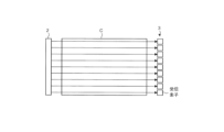
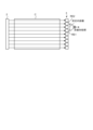
- FIG. 2 is a diagram illustrating the positional relationship between the transmitter 2, the receiver 3, and the object C.
- the transmitter 2 is placed on one side of the two opposing surfaces of the object C, and the receiver 3 is placed on the other side. , are placed respectively.
- the receiving unit 3 has a plurality of receiving elements and is configured to be able to receive the waves propagated through the object C at a plurality of receiving positions in space (black circles in FIG. 2).
- the plurality of reception positions are arranged on a plane or on a straight line that is substantially orthogonal to the wave transmission direction, and each reception element of the reception unit 3 is configured to receive signals that propagate through the object C at each of the plurality of reception positions.
- Receive waves Thereby, the receiving unit 3 receives the plane waves transmitted by the transmitting unit 2 and having a wavefront perpendicular to the propagation direction almost simultaneously by the receiving elements arranged at a plurality of receiving positions, and converts them into electrical signals. It can be output.
- the expression “substantially perpendicular” refers not only to the state in which the transmission direction and the plane or straight line are truly orthogonal, but also to the transmission direction that may occur due to installation tolerances of the transmitting section 2 and the receiving section 3, etc. It also includes a state in which the direction and the plane or straight line are slightly deviated from the state in which they are truly orthogonal.
- this figure shows a so-called transmission-reception configuration in which the transmitter 2 and the receiver 3 are placed on different sides of the object C, it is also possible to place the transmitter 2 and the receiver 3 on the same side.
- a so-called reflective system structure may also be used.
- FIG. 3A and 3B show the transmitter 2, the receiver 3, and the object C viewed from the side.
- FIG. 3A shows waves received at each reception position when there is no structure such as a defect that reflects or scatters waves inside the object C.
- the transmitting unit 2 has a configuration including a plurality of transmitting elements, for example similar to the receiving unit 3, and by aligning the timing of the transmitting signals input to each transmitting element, the transmitting unit 2 outputs the signals from each transmitting element. Generate a plane wave by aligning the wavefronts of the waves.
- the waves output from the transmitter 2 reach each receiving element of the receiver 3 at the same timing. do. That is, the plurality of receiving elements of the receiving section 3 can be regarded as receiving simultaneously a plurality of rectilinear waves (arrows in FIG. 3A) that are simultaneously transmitted from the transmitting section 2 and travel in parallel.
- FIG. 3B shows an example of waves received at each reception position when there is a structure that reflects waves, such as a defect, inside the object C.
- the wave output from the transmitter 2 travels straight through the object C.
- the rectilinear wave propagating near the defect D is reflected by the boundary surface of the defect D and reaches, for example, the second receiving element RE2 placed next to it, instead of the first receiving element RE1 that was originally supposed to reach it.
- the reflected wave Wd is received.
- the second receiving element RE2 receives both the rectilinear wave Ws1 and the reflected wave Wd.
- FIG. 3B shows how the wave is reflected at the upper side of the interface of the defect D
- a similar phenomenon can also occur at the lower side of the interface of the defect D.
- the angle at which the wave is reflected may change depending on conditions such as the angle of incidence of the wave on the defect interface, the position of incidence, and the shape of the defect.
- FIG. 3B shows how a wave is reflected outward from the center of the defect D (upward in FIG. 3B), but depending on the conditions, it can be diffracted inward from the defect center, causing the wave to There may be cases where the receiving element that the signal reaches changes.
- the waves that the receiving unit 3 receives with each receiving element change reflecting the internal structure of the object. Therefore, by processing and analyzing each received signal output from the plurality of receiving elements of the receiving section 3 using a predetermined method, it is possible to detect the presence or absence of a defect or the like inside the object.
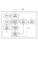
- control section 1 includes an information generation section 10, a transmission control section 11, a reception control section 12, and a defect detection section 15. Further, the information generation section 10 includes a phase shift detection section 13 and a reference signal generation section 14.
- the transmission control unit 11 controls the transmission unit 2 to transmit waves to the object C under predetermined transmission conditions such as waveform, frequency, and transmission timing.
- the reception control unit 12 controls the reception unit 3 so that the reception element placed at a predetermined reception position receives the wave transmitted by the transmission unit 2 and propagated through the object C.
- the reference signal generation unit 14 generates a reference signal that is a wave whose waveform, frequency, etc. match the transmission signal output from the transmission unit 2 using a predetermined method and configuration. As shown in FIG. 3A, the reference signal is output from each receiving element under the condition that there is no structure inside the object that causes waves such as defects to be diffracted and each of the plurality of receiving elements receives only straight waves. It is a signal equivalent to the signal, or a signal similar to this. In the present invention, various methods can be adopted as a method for generating the reference signal. The method for generating the reference signal will be described later.
- the phase shift detection section 13 Based on the reference signal, the phase shift detection section 13 generates phase shift information indicating a change in the phase of the received signal output from the reception section 3 using a predetermined method. If a significant value is detected as the phase shift information, this means that there is a structure such as a defect that causes waves to be diffracted, etc. inside the object.
- FIG. 4 is a diagram conceptually explaining the processing contents for the phase shift detection unit 13 to generate phase shift information for a received signal outputted by a receiving element at a certain receiving position.
- the received signal is either a straight wave corresponding to the receiving position or a diffracted wave due to the defect etc. for each receiving element. Or contains both ingredients.
- FIG. 4 illustrates a case where the received signal includes only diffracted wave components.
- the reference signal corresponds to a received signal that is output when the receiving element receives only a straight wave component.
- the phase shift detection unit 13 combines the received signal, which is a diffracted wave, and a reference signal, which is a straight wave, performs nonlinear processing to calculate the interference component between both signals, and based on the magnitude thereof, obtains phase shift information. generate.
- a straight wave can be expressed as cos2 ⁇ f 1 t.
- t is time.
- the diffracted wave diffracts at the defect interface and reaches the receiving element as shown in FIG. 3B, the propagation time changes compared to the straight wave, and the phase changes with respect to the straight wave. That is, if the phase shift (phase difference) between the diffracted wave and the rectilinear wave is ⁇ , the diffracted wave can be expressed as cos(2 ⁇ f 1 t ⁇ ).
- Equation (1) the third term 2cos2 ⁇ f 1 t ⁇ cos (2 ⁇ f 1 t ⁇ ) is an interference component between the received signal and the reference signal. According to the product-sum formula, the third term is expressed by Equation 2 below.
- the graph on the right side of FIG. 4 schematically shows a frequency spectrum obtained when the received signal and the reference signal interfere.
- a second harmonic component center frequency 2f 1
- a DC component are obtained due to interference between the received signal and the reference signal.
- the former term corresponds to the second harmonic component
- the latter term corresponds to the DC component, respectively.
- the magnitude of the DC component (cos ⁇ ) calculated through such processing is output to the defect detection unit 15 as phase shift information of the diffracted wave component.
- the received signal has only a diffracted wave component
- the rectilinear wave component included in the received signal and the reference signal have the same waveform and frequency, and have a time difference corresponding to the time required for the rectilinear wave component to propagate through the object C.
- the reference signal has a sufficiently large amplitude and is combined with the received signal, the straight wave component included in the received signal can be ignored, so the nonlinear processing described above eliminates the interference component between the diffracted wave component in the received signal and the reference signal. can be generated.
- the reference signal generation unit 14 generates a reference signal using a predetermined method. Below, a method for generating the reference signal will be explained.
- the reference signal generation unit 14 generates the reference signal by, for example, performing a simulation using a calculation model of the target object.
- the computational model of the object is a virtual object created in arithmetic space that has internal parameters that substantially match those of the object C that is the inspection target of the non-destructive inspection device 100 and that has no internal defects. It's a model.
- the expression "substantially match” includes a case where there is a slight deviation in value between the internal parameters of the calculation model and the internal parameters of the object C due to an error or the like.
- a calculation model is generated based on a known parameter group such as physical property parameters and structural parameters that are required when designing and manufacturing the object C. Note that the calculation model does not necessarily need to be created by the non-destructive testing apparatus 100, and may be created by a separately provided external computer or the like.
- a wave having the same wave parameters (amplitude, phase, frequency, etc.) as the transmission signal output from the transmitting section 2 is input into the calculation model, and a plurality of receiving elements of the receiving section 3 are arranged respectively.
- a received signal observed at the same position as the receiving position is obtained through simulation and is used as a reference signal. Note that the simulation does not necessarily need to be performed by the nondestructive testing apparatus 100, and may be performed by a separately provided external computer or the like.
- the object to be non-destructively inspected is constructed as a calculation model in an arithmetic space, and a reference signal is generated by simulating wave propagation based on an actual transmitted signal.
- a reference signal is generated by simulating wave propagation based on an actual transmitted signal.
- the reference signal can be generated at a timing different from the timing at which the nondestructive inspection apparatus 100 performs the nondestructive inspection of the object C. That is, the reference signal generation unit 14 may generate the reference signal at the same timing when the non-destructive inspection apparatus 100 performs the actual inspection of the object C in real space, or may generate the reference signal at the same timing as when the non-destructive inspection apparatus 100 performs the actual inspection of the object C.
- the reference signals may be generated at different timings. For example, by generating a reference signal in advance of an actual non-destructive inspection and storing the data in a storage unit, etc. of the reference signal generation unit 14, the non-destructive inspection apparatus 100 during the actual inspection can be It is possible to reduce the workload and perform efficient inspections. Alternatively, the reference signal may be generated after the actual inspection.
- the object C to be subjected to non-destructive testing is made of a homogeneous material, but this is not necessarily the case, and objects with non-homogeneous materials or structures may also be used. It's okay.
- the present invention can also be applied to materials based on resin materials that contain fibers, such as CFRTP (Carbon Fiber Reinforced Thermo Plastics), which is a type of composite fiber resin, and materials that have a laminated structure such as CFRP.
- CFRTP Carbon Fiber Reinforced Thermo Plastics
- the destructive inspection device 100 is applicable.
- the defect detection section 15 detects the presence or absence of a defect, etc. inside the object C, and the size and position of the defect, etc., based on the phase shift information output from the phase shift detection section 13.
- the defect detection unit 15 detects a defect detection unit 15 when there is a reception position where significant phase shift information is detected among the reception positions where a plurality of reception elements of the reception unit 3 are arranged, or when there is a reception position that is unique compared to other reception positions. If there is a reception position from which phase shift information can be obtained, it is determined that a defect or the like exists within the object C. Note that the defect detection unit 15 determines that a defect or the like exists on or near a line connecting the receiving position and the transmitting unit 2 from which significant or unique phase shift information can be obtained.
- the nondestructive inspection device 100 propagates waves to a target object, acquires a received signal with receiving elements arranged at a plurality of receiving positions, and performs nonlinear processing on the received signal with a reference signal created or acquired in advance. By generating phase shift information of the received signal, even if the defect inside the object is minute, it can be detected easily and at low cost.
- the reference signal can be generated by a simulation in which a wave having the same parameters (frequency, etc.) as the wave transmitted by the transmitter 2 is input into a calculation model having internal parameters equivalent to those of the target object. It is possible to reduce the generation cost of , and the calculation cost of phase shift detection processing based on the reference signal and the received signal, thereby suppressing the inspection cost by the non-destructive inspection apparatus 100.
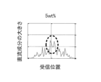
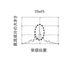
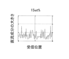
- FIGS. 5 and 6 show the relationship between the magnitude of the DC component included in the phase shift information output from the phase shift detection unit 13 and the reception position, respectively, using the content rate of carbon fiber in CFRTP as a parameter.
- the case where there is a gap with a diameter of 500 ⁇ m inside (FIG. 5) and the case where there is no gap (FIG. 6) are shown.
- the horizontal axis indicates the receiving position
- the vertical axis indicates the magnitude of the DC component of the phase shift information, respectively. Note that the air gap is located between the center of the horizontal axis (receiving position) in FIGS. 5 and 6 and the transmitting section.
- FIGS. 5A to 5D and FIGS. 6A to 6D show the carbon fiber content as a parameter.
- the carbon fiber content is 5% by weight
- the carbon fiber content is the same.
- 10% by weight FIGS. 5C and 6C show the case of 15% by weight
- FIGS. 5D and 6D show the case of 20% by weight, respectively.
- the variation in phase shift information (random vertical fluctuation) mainly seen in FIG. 6 is considered to be due to the influence of scattering etc. due to carbon fibers contained in CFRTP.
- the peak of the phase shift information caused by defects etc. is larger than the variation due to internal scattering etc.
- the non-destructive testing apparatus 100 As described above, according to the non-destructive testing apparatus 100 according to the first embodiment, even when the object contains fibers and the like and is not homogeneous, defects in the object can be easily and efficiently detected. Can be done.
- each receiving element (first receiving position) of the receiving section 3 is The received signal obtained by simulating the received signal in arithmetic space was used.
- a received signal at a second receiving position different from the first receiving position is used as a reference signal used to generate phase shift information at the first receiving position.
- FIG. 7 is a diagram showing an example of the configuration of a non-destructive testing apparatus 100A according to the second embodiment.
- the nondestructive testing apparatus 100A includes a control section 1A, a transmitting section 2, and a receiving section 3.
- the control section 1A includes an information generation section 10A, a transmission control section 11, a reception control section 12, and a defect detection section 15, and the information generation section 10A includes only a phase shift detection section 13A.
- components that perform operations similar to those in the first embodiment are given the same reference numerals as in the first embodiment, and descriptions thereof will be omitted.
- a non-destructive testing apparatus 100A according to the second embodiment shown in FIG. 7 differs from the non-destructive testing apparatus 100 according to the first embodiment in that it does not have a reference signal generation section 14.
- the phase shift detection section 13A uses another signal as the reference signal instead of the reference signal generated by the reference signal generation section 14 to detect the phase shift. process
- FIG. 8 is a diagram for explaining phase shift detection processing in the nondestructive testing apparatus 100A according to the second embodiment.
- FIG. 8 conceptually explains phase shift detection processing for the received signal generated by the first receiving element RE1 among the plurality of receiving elements.
- the received signal generated by the first receiving element RE1 the received signal generated by another receiving element disposed at a receiving position separated from the first receiving element RE1 by a predetermined distance is used as a reference signal.
- the phase shift detection process is performed using the FIG. 8 shows an example in which a received signal generated by another receiving element (second receiving element RE2) placed two reception positions adjacent to the first receiving element RE1 is used as a reference signal.
- the second embodiment and the first embodiment differ only in which signal is used as the reference signal, and the content of the phase shift detection process performed by the phase shift detection unit 13A is the same as the first embodiment. This is equivalent to the phase shift detection section 13 of the embodiment.
- phase shift detection processing is performed on the received signals generated by all the receiving elements, using the received signals generated by other receiving elements located a predetermined distance away as reference signals.
- phase shift detection processing even if the received signal generated by the first receiving element contains a diffracted wave component diffracted by a defect inside the object, the second receiving element located a predetermined distance away It is expected that the received signal generated by the element contains only straight wave components. In such a case, the phase shift information of the received signal can be extracted by performing the same phase shift detection process as in the first embodiment.
- the phase shift detection mechanism of the present invention is based on so-called correlation processing, and while the phase shift detection unit 13 in the first embodiment operates based on the principle of cross-correlation, the second embodiment operates based on the principle of cross-correlation.
- the phase shift detection unit 13A in the embodiment operates based on the principle of autocorrelation. Therefore, in the phase shift detection section 13A, the reference signal may be a received signal outputted by any receiving element separated by a predetermined distance in any direction from the receiving element that outputs the received signal, but more preferably , is appropriately determined depending on the amount of phase shift of the received signal to be detected and the size of defects etc. that are assumed to be included in the object.
- the results of correlation processing using multiple received signals output from multiple receiving elements separated by different distances, or by further performing statistical processing such as averaging on the results, more stable It is possible to extract phase shift information.
- the manufacturing cost for the reference signal generation unit 14 is reduced compared to the non-destructive testing device 100 of the first embodiment, and Non-destructive testing can be performed efficiently.
- FIG. 9 shows the relationship between the magnitude of the DC component included in the phase shift information output from the phase shift detection section 13A and the reception position, using the carbon fiber content rate of CFRTP as a parameter.
- Fig. 9A shows the case where the carbon fiber content is 5% by weight
- Fig. 9B shows the case when the carbon fiber content is 10% by weight
- Fig. 9C shows the case when the carbon fiber content is 15% by weight
- Fig. 9D shows the case when the carbon fiber content is 20% by weight.
- the horizontal axis in FIG. 9 indicates the receiving position
- the vertical axis indicates the magnitude of the DC component of the phase shift information. position) between the center of the transmitter and the transmitter.
- the phase shift information shows a peak depending on the position of the defect etc., similarly to FIG. 5. That is, when there is a defect inside the object, the phase shift information at the reception position corresponding to the defect position exhibits a peculiar behavior with respect to other reception positions.
- the non-destructive inspection apparatus 100A according to the second embodiment can also detect defects in the target object simply and efficiently.
- FIG. 10 is a diagram showing an example of the configuration of a non-destructive testing apparatus 100B according to the third embodiment.
- a non-destructive testing apparatus 100B includes a control section 1B, a transmitting section 2, and a receiving section 3. Further, the control section 1B includes an information generation section 10B, a transmission control section 11, a reception control section 12, and a defect detection section 15, and the information generation section 10B includes a phase shift detection section 13 and a reference signal generation section. 14, a nonlinear processing section 16, and a difference extraction section 17.
- the nondestructive inspection apparatus 100B further includes a nonlinear processing section 16 and a difference extraction section 17 in addition to the configuration of the nondestructive inspection apparatus 100.
- the nonlinear processing unit 16 performs nonlinear processing (product calculation) only on the reference signal for each receiving position. More specifically, the nonlinear processing unit 16 performs a square calculation on the reference signal and outputs the result.
- the difference extraction unit 17 extracts the difference between the phase shift information generated by the phase shift detection unit 13 and the nonlinear processing result generated by the nonlinear processing unit 16 for each reception position, and outputs the difference to the defect detection unit 15.
- the defect detection unit 15B uses this difference to determine the presence or absence of a defect.
- the non-destructive testing apparatus 100B it is possible to reduce the influence of variations in the reference signal for each reception position and more stably detect defects in the object. can.
- variations in the reference signal for each receiving position may occur due to the influence of wave scattering due to fibers, etc., for example, when a material that is not homogeneous is used as the object.
- the fourth embodiment differs from the first embodiment in that phase shift detection processing is performed on each of the received signal and the reference signal after removing the amplitude fluctuation (intensity) component.
- FIG. 11 is a diagram showing an example of the configuration of a non-destructive testing apparatus 100C according to the fourth embodiment.
- a non-destructive testing apparatus 100C includes a control section 1C, a transmitting section 2, and a receiving section 3. Further, the control section 1C includes an information generation section 10C, a transmission control section 11, a reception control section 12, and a defect detection section 15.
- the information generation section 10C includes a phase shift detection section 13, a reference signal generation section 14 , a first amplitude fluctuation removal section 18 , and a second amplitude fluctuation removal section 19 .
- the nondestructive testing apparatus 100C further includes a first amplitude fluctuation removing section 18 and a second amplitude fluctuation removing section 19.
- the first amplitude fluctuation removal unit 18 performs a process of removing the amplitude fluctuation component from the received signal generated by the reception unit 3 for each reception position.
- the second amplitude fluctuation removal unit 19 performs processing to remove the amplitude fluctuation component from the reference signal for each reception position corresponding to the reception position.
- the phase shift detection section 13 detects a change in the phase of the received signal output from the first amplitude fluctuation removal section 18 based on the reference signal output from the second amplitude fluctuation removal section 19. Generates phase shift information indicating .
- amplitude fluctuation removal processing is binarization processing using a predetermined threshold.
- the predetermined threshold value may be set to an appropriate value in advance. Further, as another example, saturation processing or clipping processing may be performed when the signal amplitude exceeds a predetermined value.
- the nondestructive testing apparatus 100C it is possible to reduce the influence of amplitude fluctuations of the received signal and the reference signal, and detect defects in the object with higher accuracy.
- the first amplitude fluctuation removal section 18 that performs amplitude fluctuation removal processing on the received signal and the second amplitude fluctuation removal section 19 that performs amplitude fluctuation removal processing on the reference signal are separately provided.
- the same amplitude fluctuation removal section may perform amplitude fluctuation removal processing on both the received signal and the reference signal.
- defects are detected by extracting information regarding the phase of the received signal.
- defects are detected using not only the phase shift information of the received signal but also the intensity information.
- FIG. 12 is a diagram showing an example of the configuration of a non-destructive testing device 100D according to the fifth embodiment.
- a non-destructive testing apparatus 100D includes a control section 1D, a transmitting section 2, and a receiving section 3. Further, the control section 1D includes an information generation section 10D, a transmission control section 11, a reception control section 12, a defect detection section 15D, a branching section 110, and an intensity information processing section 111. , a phase shift detection section 13, and a reference signal generation section 14.
- the nondestructive testing device 100D further includes a branching section 110 and a strength information processing section 111 in addition to the configuration of the nondestructive testing device 100.
- the branching section 110 branches the received signal output from the receiving section 3, and the phase shift detection section 13 outputs phase shift information of one of the branched received signals.
- the intensity information processing unit 111 performs predetermined processing on the other received signal branched by the branching unit 110 based on the intensity information of the received signal, such as extracting the intensity information.
- the defect detection unit 15D detects defects based on the phase information generated by the phase shift detection unit and the output information from the intensity information processing unit 111.
- the predetermined processing that the intensity information processing section 111 performs on the intensity information of the received signal and the predetermined processing that the defect detection section 15D performs on the phase shift information and the output information from the intensity information processing section 111 are described in this document.
- the invention is not particularly limited. As appropriate, it is possible to use known techniques for detecting defects and the like based on strength information of received signals.
- the reference signal generation unit 14 generated the reference signal
- the nondestructive testing device of the present invention may acquire a reference signal generated in advance by an external computer or the like, and perform testing using this.
- the non-destructive testing device of the present invention may store information regarding the reference signal generated in advance in a storage unit or the like, and read out and use the information from the storage unit during phase shift detection processing. good.
- the method for generating the reference signal is not limited to the above method, and for example, if the reference signal is obtained by actual measurement, this method may be used or used in combination.
- the reference signal is generated by simulation using a calculation model of the target object, but the present disclosure is not limited thereto.
- a calculation model of the object in arithmetic space we prepare another object (reference object) that is made of the same material, has the same structure, and does not contain any defects as the actual object for non-destructive testing, and It is also possible to actually input the wave to the reference object, obtain the data of the received signal, and create the reference signal based on this data.
- the transmitter 2 transmits a plane wave to the object C, but the present disclosure is not limited thereto.
- a spherical wave may be used.
- straight waves may be transmitted from a plurality of transmission positions corresponding to each of the plurality of reception positions. In this case, it is not necessary to transmit straight waves from all transmission positions at the same time, and transmission may be performed sequentially from a plurality of transmission positions, and a reception signal may be acquired at a reception position corresponding to the transmission position. In this case, by using the information on the transmission time and the reception time, it is possible to perform the same phase shift detection process as in the embodiment described above.
- the present invention is useful for non-destructive testing equipment.
- Nondestructive inspection device 1, 1A, 1B, 1C, 1D Control section 10, 10A, 10B, 10C, 10D Information generation section 11 Transmission control section 12 Reception control section 13, 13A Phase shift detection Section 14 Reference signal generation section 15, 15B, 15D Defect detection section 16 Nonlinear processing section 17 Difference extraction section 18 First amplitude fluctuation removal section 19 Second amplitude fluctuation removal section 110 Branching section 111 Intensity information processing section 2 Transmission section 3 Receiving section
Landscapes
- Engineering & Computer Science (AREA)
- Signal Processing (AREA)
- Physics & Mathematics (AREA)
- Health & Medical Sciences (AREA)
- Life Sciences & Earth Sciences (AREA)
- Chemical & Material Sciences (AREA)
- Analytical Chemistry (AREA)
- Biochemistry (AREA)
- General Health & Medical Sciences (AREA)
- General Physics & Mathematics (AREA)
- Immunology (AREA)
- Pathology (AREA)
- Investigating Or Analyzing Materials By The Use Of Ultrasonic Waves (AREA)
Abstract
低コストで、微小な欠陥をも検出することができる非破壊検査装置、非破壊検査方法、およびプログラムを提供する。本発明の非破壊検査装置は、対象物に対して波動を送信する送信部と、前記波動の送信方向に対して直交する線上または面上の複数の受信位置において、前記対象物媒介して伝搬された前記波動を受信して受信信号を生成する受信部と、前記受信信号および所定の基準信号に対して所定の非線形処理を行い、前記受信位置のそれぞれにおける前記受信信号と前記基準信号との位相ずれを示す位相ずれ情報を生成する情報生成部とを備える。
Description
本発明は、非破壊検査装置、非破壊検査方法、およびプログラムに関する。
近年、環境問題やエネルギー問題等を背景に、CFRP(Carbon Fiber Reinforced Plastic)等の複合繊維強化樹脂材が、航空機や自動車等の移動体のボディをはじめ、橋梁や道路等の比較的大型の施設や建造物の構造材として用いられる例が増えつつある。このような複合材は、金属等に比べて軽量かつ高強度という優れた特徴を備えるが、製造時等に微細なボイド(空隙)や内部剥離等があると、経年劣化により大きな破壊や破断に至る可能性が指摘されている。また、大規模建築物に用いられることの多いコンクリートは、製造または施工された当初は高い強靭性を有するが、経年による特性変化や水分の侵入等により、コンクリート中にす(空隙)や内部鉄筋の腐食などが生じ、その強度が大きく劣化することがある。そこで、このような移動体、インフラ、建造物等の安全性や信頼性を効率良く評価し担保するために、非破壊検査が実施されている。
さらに、最近では、製品安全性に関する消費者マインドの向上や、これに伴う規制強化の動き等から、食料品を含む消費財全般に対して高い安全性を求める社会的風潮が強まっており、これらの品質を簡便に評価する非破壊検査方法が求められている。
従来、このような非破壊検査には、打音検査や外観検査等、職人のノウハウや人海戦術に基づくアナログ的手法が多く用いられてきた。しかしながら、アナログ的手法は、それら技術の維持または継承が難しく、効率性の観点においても課題が多い。そのため、より定量性があり、作業効率が高く短時間で実施できる非破壊検査手法が必要とされている。
そこで、このような効率的かつ定量性のある非破壊検査手法として、電磁波や超音波等の波動を用いた非破壊検査方法が提案、実用化されている。このような非破壊検査方法の代表的な手法として、超音波探傷法等が知られている。超音波探傷法は、対象物に対して超音波センサを当接させて超音波を対象物に入射し、対象物から反射された超音波、もしくは対象物を透過した超音波を観測することにより、対象物内の構造や、ボイドや亀裂等の欠陥の有無を把握しようとするものである。
超音波探傷法として最も一般的な構成の一例を、図13Aに示す。図13Aには、対象物に対して超音波送信用および受信用の2つセンサを配置し、一方のセンサから対象物に対して超音波を送信し、対象物によって反射されてきた超音波を他方のセンサによって受信する構成が示されている。この構成は、対象物内のボイド等欠陥による音響インピーダンスの不連続に起因した超音波の反射エネルギーを計測することで、ボイド等の有無やその大きさを検出する。
また、特許文献1には、上記のような超音波エネルギーを検出する方式に代えて、対象物に対して互いに周波数が異なる2つの超音波を送信し、これら2つの超音波が内部欠陥等を透過または反射した場合に生じる位相変動に起因した受信信号中のうなり波形(ビート)に基づいて欠陥の有無を判定する非破壊検査装置が開示されている。
しかしながら、図13に例示した手法は、内部欠陥等の界面で反射される超音波のエネルギー量を検出するという基本原理に起因して、当該欠陥等の大きさにより検出性能が左右される。このため、図13Bに示すように、大きな欠陥は精度よく検出できるが、対象物の劣化過程のごく初期等に見られる微小な亀裂等の小さな欠陥は検出が困難な場合がある。
特許文献1に開示された非破壊検査装置では、超音波の位相変動を観測することで、図13に示した方法よりも小さな欠陥等を検出することが期待できる。しかし、互いに異なる周波数の超音波を送信するために2つの送信部を設ける必要があり、非破壊検査装置のコストが増大する可能性が高い。
さらに、これらの従来技術においては、欠陥等を検出するための解析対象となる超音波データを、実際に対象物に超音波を伝搬させて実測により取得する必要がある。このため、当該検査作業全般に関して時間面や設備面のコスト負担が大きいという課題もある。例えば、特許文献1に開示される非破壊検査装置のように対象物を伝搬する波動の位相変動を検出するためには、何らかの基準信号が必要となる。しかしながら、このような基準信号のデータを取得するために、検査対象物と同じ内部パラメータを有し、かつ欠陥が存在しないことが予め判っている他の対象物を実際に用意することは、非常に困難である、または大きなコストを要する。
したがって、本発明は、対象物に超音波を伝搬させて得られる時系列信号データから、簡便かつ低コストで超音波の位相変動を検出することができる非破壊検査装置、非破壊検査方法、およびプログラムを提供することを目的とする。
上記課題を解決するため、本発明の一態様に係る非破壊検査装置は、
対象物に対して波動を送信する送信部と、
前記波動の送信方向に対して略直交する線上または面上の複数の受信位置において、前記対象物により伝搬された波動を受信して受信信号を生成する受信部と、
前記受信信号、もしくは実験空間または算術空間において、前記対象物と異なる所定の対象物に超音波を伝搬させて取得した受信信号を基準信号として出力し、当該基準信号と前記受信信号に対して非線形処理を行い、前記受信位置のそれぞれにおける前記受信信号と前記基準信号との位相ずれを示す位相ずれ情報を生成する情報生成部と、
を備えることを特徴とする。
対象物に対して波動を送信する送信部と、
前記波動の送信方向に対して略直交する線上または面上の複数の受信位置において、前記対象物により伝搬された波動を受信して受信信号を生成する受信部と、
前記受信信号、もしくは実験空間または算術空間において、前記対象物と異なる所定の対象物に超音波を伝搬させて取得した受信信号を基準信号として出力し、当該基準信号と前記受信信号に対して非線形処理を行い、前記受信位置のそれぞれにおける前記受信信号と前記基準信号との位相ずれを示す位相ずれ情報を生成する情報生成部と、
を備えることを特徴とする。
また、本発明の一態様に係る非破壊検査方法は、
コンピュータが実行する非破壊検査方法であって、
対象物に対して波動を送信し、
前記波動の送信方向に対して略直交する線上または面上の複数の受信位置において、前記対象物により伝搬された前記波動を受信して受信信号を生成し、前記受信信号、もしくは実験空間または算術空間において、前記対象物と異なる所定の対象物に超音波を伝搬させて取得した受信信号を基準信号として出力し、当該基準信号と前記受信信号に対して非線形処理を行い、前記受信位置のそれぞれにおける前記受信信号と前記基準信号との位相のずれを示す位相ずれ情報を生成することを特徴とする。
コンピュータが実行する非破壊検査方法であって、
対象物に対して波動を送信し、
前記波動の送信方向に対して略直交する線上または面上の複数の受信位置において、前記対象物により伝搬された前記波動を受信して受信信号を生成し、前記受信信号、もしくは実験空間または算術空間において、前記対象物と異なる所定の対象物に超音波を伝搬させて取得した受信信号を基準信号として出力し、当該基準信号と前記受信信号に対して非線形処理を行い、前記受信位置のそれぞれにおける前記受信信号と前記基準信号との位相のずれを示す位相ずれ情報を生成することを特徴とする。
また、本発明の一態様に係るプログラムは、
非破壊検査装置が有するコンピュータが実行するプログラムであって、
対象物に対して波動を送信し、
前記波動の送信方向に対して略直交する線上または面上の複数の受信位置において、前記対象物により伝搬された前記波動を受信して受信信号を生成し、
前記受信信号、もしくは実験空間または算術空間において、前記対象物と異なる所定の対象物に超音波を伝搬させて取得した受信信号を基準信号として出力し、当該基準信号と前記受信信号に対して非線形処理を行い、前記受信位置のそれぞれにおける前記受信信号と前記基準信号との位相のずれを示す位相ずれ情報を生成する、
という手順を前記コンピュータに実行させることを特徴とする。
非破壊検査装置が有するコンピュータが実行するプログラムであって、
対象物に対して波動を送信し、
前記波動の送信方向に対して略直交する線上または面上の複数の受信位置において、前記対象物により伝搬された前記波動を受信して受信信号を生成し、
前記受信信号、もしくは実験空間または算術空間において、前記対象物と異なる所定の対象物に超音波を伝搬させて取得した受信信号を基準信号として出力し、当該基準信号と前記受信信号に対して非線形処理を行い、前記受信位置のそれぞれにおける前記受信信号と前記基準信号との位相のずれを示す位相ずれ情報を生成する、
という手順を前記コンピュータに実行させることを特徴とする。
本発明によれば、対象物に超音波を伝搬させて得られる時系列信号データから、簡便かつ低コストで超音波の位相変動を検出することができる。
以下、本発明の実施形態について、図面を参照して説明する。ただし、発明の範囲は、図示した例に限定されるものではなく、これに準ずる形態および構成を含むものとする。なお、以下の説明において、同一の機能および構成を有するものについては、同一の符号を付し、その説明を省略する。
[第1の実施形態]
(非破壊検査装置100の全体構成)
図1は、第1の実施形態に係る非破壊検査装置100の構成の一例を示す図である。図1に示すように、非破壊検査装置100は、制御部1と、送信部2と、受信部3とを備え、内部にコンピュータを有するコンピュータ機器の一種である。本構成により、非破壊検査装置100は、対象物の欠陥の有無等の検査を非破壊で行う。非破壊検査の対象物としては、代表的な例として、CFRP等の複合繊維樹脂や鉄筋コンクリート等の固体物が挙げられるが、これに限定されるものではなく、液体、気体も想定される。また、以下では、対象物が六面体である場合について説明を行うが、対象物の形状はこれに限定されず、例えば、球体、楕円体、円柱、楕円柱、角柱、不定形等であっても良い。
制御部1は、例えばCPU(Central Processing Unit)、マイクロプロセッサ等のプロセッサ、または、ASIC(Application Specific Integrated Circuit)、FPGA(Field Programmable Gate Array)等の演算回路で構成され、複数の機能ブロックを有する。制御部1は、複数の機能ブロックにより、送信部2に対して波動の送信タイミングや送信波形等の送信条件に関する制御情報を提供し、受信部3に対して制御情報を提供すると共に、受信部3から出力される波動の受信信号に対する所定の信号処理等を施して、検査結果を出力または表示する。
送信部2は、制御部1から提供される制御情報に基づいて、対象物に対して所定の波動を送信する。送信部2が送信する波動の例としては、超音波等の音響波、電波や光波等の電磁波が挙げられるが、以下では、送信部2は超音波を送信するものとする。送信部2が送信する波動の波面形状としては、平面波、球面波等が想定されるが、以下では、平面波、すなわち伝搬方向に対して垂直な方向に波面を有する波動であるものとする。また、送信部2を構成する波動発生素子は、所望の波面形状を得ることができれば、単一素子構成、もしくは複数素子構成のいずれでも良い。
受信部3は、例えば対象物を挟んで送信部2と対面するように配置され、制御部1から提供される制御情報に基づいて、送信部2から送信され対象物Cを伝搬した波動を受信する。図2は、送信部2、受信部3、および対象物Cの位置関係を例示した図で、対象物Cの互いに対向する2面の一方側に送信部2を、他方側に受信部3を、それぞれ配置している。
受信部3は、複数の受信素子を有し、対象物Cを伝搬した波動を、空間内の複数の受信位置(図2の黒丸)において受信できるように構成されている。複数の受信位置は、波動の送信方向に対して略直交する平面上または直線上に配置されており、受信部3の各受信素子は、複数の受信位置のそれぞれにおいて、対象物Cを伝搬した波動を受信する。これにより、受信部3は、送信部2が送信し、伝搬方向に垂直な波面を有する平面波を、複数の受信位置に配列された受信素子によってそれぞれほぼ同時に受信して、電気信号に変換し、出力することができる。
なお、本明細書において、略直交するとの記載は、送信方向と平面または直線とが真に直交している状態だけでなく、例えば送信部2および受信部3の設置公差等により生じうる、送信方向と平面または直線とが真に直交した状態からわずかにずれた状態をも含むものとする。
なお、本図では、対象物Cに対して、互いに異なる側に送信部2および受信部3を配置したいわゆる透過系の送受信構成を示したが、送信部2および受信部3を同じ側に配置したいわゆる反射系の構成としても良い。
ここで、図3を参照して、対象物Cにより伝搬される波動について説明する。図3Aおよび図3Bは、送信部2、受信部3、および対象物Cを側面視した状態を示している。図3Aは、対象物Cの内部に、欠陥等の波動を反射または散乱等する構造が存在しない場合において、受信位置毎に受信される波動を示している。図3Aでは、送信部2は、例えば受信部3と同様に、複数の送信素子でなる構成を有し、各送信素子に入力する送信信号のタイミングを揃えることにより、各送信素子から出力される波動の波面を揃えて平面波を生成する。図3Aでは、対象物C内部に波動の反射や散乱等、波動伝搬を遅延させる要因が存在しないため、送信部2から出力された波動は、そのまま同じタイミングで受信部3の各受信素子に到達する。すなわち、受信部3の複数の受信素子は、送信部2から同時に送信され、併進する複数の直進波(図3Aの矢印)をそれぞれ同時に受信するものとみなすことができる。
一方、図3Bは、対象物Cの内部に、欠陥等の波動を反射等する構造が存在する場合において、受信位置毎に受信される波動の一例を示している。図3Bでは、図3Aと同様に、送信部2から出力された波動が対象物C内を直進する。しかし、欠陥D近傍を伝搬する直進波は欠陥Dの境界面により反射され、本来到達するはずだった第1の受信素子RE1ではなく、例えば隣に配置されている第2の受信素子RE2に到達し、反射波Wdが受信される。これにより、図3Bに示す例では、第2の受信素子RE2は、直進波Ws1と反射波Wdの両方を受信することになる。
なお、図3Bには、波動が欠陥Dの界面上側部において反射される様子を示しているが、同様の現象は欠陥Dの界面下側部においても生じ得る。また、波動の欠陥界面への入射角度、入射位置、欠陥の形状等の条件によっては、反射する角度は変化する場合がある。例えば、図3Bには、波動が欠陥Dの中心から外側(図3Bでは上方向)に向かって反射する様子を示しているが、条件次第で欠陥中心から内側に回折し、これにより、当該波動が到達する受信素子が変化する場合があり得る。なお、欠陥正面に到達した波動Ws2は、その多くが欠陥により伝搬方向と逆方向に反射されるため、波動の伝搬方向における欠陥の裏側(図3Bでは右側)に位置する受信素子には、いずれの波動も受信されない。
このように、受信部3が各受信素子で受信する波動は、対象物の内部構造等を反映して変化する。従って、受信部3の複数の受信素子から出力される各受信信号を所定の方法で処理および解析することにより、対象物内部の欠陥等の有無を検出することができる。
(制御部1)
図1に戻り、制御部1が有する各機能ブロックの動作について説明する。図1に示すように、制御部1は、情報生成部10と、送信制御部11と、受信制御部12と、欠陥検出部15とを備える。また、情報生成部10は、位相ずれ検出部13と、基準信号生成部14とを備える。
図1に戻り、制御部1が有する各機能ブロックの動作について説明する。図1に示すように、制御部1は、情報生成部10と、送信制御部11と、受信制御部12と、欠陥検出部15とを備える。また、情報生成部10は、位相ずれ検出部13と、基準信号生成部14とを備える。
送信制御部11は、波形、周波数、送信タイミング等の所定の送信条件で波動を対象物Cに対して送信するように送信部2を制御する。
受信制御部12は、送信部2により送信され、対象物Cを伝搬した波動を、所定の受信位置に配置した受信素子が受信するように受信部3を制御する。
基準信号生成部14は、所定の方法および構成により、送信部2から出力される送信信号と波形、周波数等が一致する波動である基準信号を生成する。基準信号は、図3Aに示すように、対象物の内部に欠陥等の波動を回折等させる構造が存在せず複数の受信素子がそれぞれ直進波のみを受信する条件において各受信素子から出力される信号と同等の信号、もしくはこれに準ずる信号である。本発明において、基準信号の生成方法としては種々の方法が採用され得る。基準信号の生成方法については、後述する。
位相ずれ検出部13は、基準信号に基づいて、所定の方法により受信部3から出力される受信信号の位相の変化を示す位相ずれ情報を生成する。位相ずれ情報として有意な値が検出された場合、対象物の内部に欠陥等の波動を回折等させる構造が存在することになる。
<位相ずれ情報の生成方法>
位相ずれ情報の生成方法について説明する。図4は、ある受信位置の受信素子が出力した受信信号について、位相ずれ検出部13が位相ずれ情報を生成するための処理内容を概念的に説明した図である。上記したように、受信信号は、対象物の内部の欠陥等の位置や大きさに依存して、受信素子毎に、当該受信位置に対応する直進波と、欠陥等による回折波とのいずれかまたは両方の成分を含む。
位相ずれ情報の生成方法について説明する。図4は、ある受信位置の受信素子が出力した受信信号について、位相ずれ検出部13が位相ずれ情報を生成するための処理内容を概念的に説明した図である。上記したように、受信信号は、対象物の内部の欠陥等の位置や大きさに依存して、受信素子毎に、当該受信位置に対応する直進波と、欠陥等による回折波とのいずれかまたは両方の成分を含む。
図4は、受信信号が回折波成分のみを含む場合について例示している。また、基準信号は、受信素子が直進波成分のみを受信した場合に出力される受信信号に相当する。位相ずれ検出部13は、回折波である受信信号と直進波に相当する基準信号とを合成し、非線形処理を行って両信号間の干渉成分を算出し、その大きさに基づいて位相ずれ情報を生成する。
ここで、送信部2から送信される波動の周波数をf1とすると、例えば直進波はcos2πf1tと表すことができる。tは時間である。一方、回折波は、図3Bに示すように欠陥界面で回折して受信素子に到達するため、直進波に比して当該伝搬時間が変動し、直進波を基準として当該位相が変化する。即ち、回折波と直進波との位相ずれ(位相差)をθとすると、回折波は、cos(2πf1t-θ)と表すことができる。
受信信号(回折波)と基準信号(直進波)とを合成(加算)し、非線形処理の例として積演算を施した場合の出力値は、以下の式1で表される。

式(1)において、第3項の2cos2πf1t・cos(2πf1t-θ)が受信信号と基準信号との干渉成分である。積和の公式により、第3項は以下の式2で表される。

図4中の右側のグラフは、受信信号と基準信号が干渉した場合に得られる周波数スペクトルを模擬的に示している。これに示されるように、受信信号と基準信号との干渉により、第2高調波成分(中心周波数2f1)と直流成分が得られる。式(2)において、前項が第2高調波成分に、後項が直流成分に、それぞれ相当する。
このような処理により算出された直流成分(cosθ)の大きさが、回折波成分の位相ずれ情報として欠陥検出部15に出力される。
なお、上記においては、受信信号が回折波成分のみを有する場合について説明したが、受信信号が、回折波成分および直進波成分を有する場合についても、ほぼ同様の動作および効果を示すことになる。すなわち、受信信号に含まれる直進波成分と基準信号は、同一の波形および周波数を有し、対象物Cを直進波成分が伝搬するに要する時間に相当する時間差を有するものとなる。この場合、基準信号を十分大きい振幅として受信信号と合成すれば、受信信号に含まれる直進波成分は無視できるため、上記非線形処理により、受信信号中の回折波成分と基準信号との干渉成分を生成することができる。
基準信号生成部14は、所定の方法により基準信号を生成する。以下では、基準信号の生成方法について説明する。
<基準信号の生成方法>
基準信号生成部14は、例えば、対象物の計算モデルを用いてシミュレーションを行うことで生成する。
基準信号生成部14は、例えば、対象物の計算モデルを用いてシミュレーションを行うことで生成する。
対象物の計算モデルとは、非破壊検査装置100の検査対象である対象物Cと略一致する内部パラメータを有し、かつ内部に欠陥等が存在しない仮想の対象物を算術空間内に作成したモデルである。なお、本明細書において、略一致するとの記載は、計算モデルの内部パラメータと対象物Cの内部パラメータとの間に、誤差等に起因するわずかな値のずれが含まれる場合を含むものとする。より具体的には、対象物Cの設計および作製等を行う際に必要となる物性パラメータや構造パラメータ等の既知のパラメータ群に基づいて計算モデルを生成する。なお、計算モデルの作成は、必ずしも非破壊検査装置100が行う必要はなく、別途設けられた外部のコンピュータ等によって作成されても良い。
次に、計算モデルを用いた基準信号の生成方法の例を説明する。算術空間において、送信部2から出力される送信信号と同じ波動パラメータ(振幅、位相、周波数等)を有する波動を計算モデルに入力し、受信部3が有する複数の受信素子がそれぞれ配置されている受信位置と同じ位置において観測される受信信号をシミュレーションにより取得し、基準信号とする。なお、シミュレーションは、必ずしも非破壊検査装置100が行う必要はなく、別途設けられた外部のコンピュータ等によって実施されても良い。
このように、非破壊検査の対象物を算術空間内に計算モデルとして構築し、実際の送信信号に準じた波動伝搬をシミュレーションすることによって基準信号を生成する。これにより、欠陥等のない対象物を実際に用意して、送信部2および受信部3を用いて波動を伝搬し、当該受信信号を基準信号とするよりも、容易かつ低コストに基準信号を取得することができる。何故なら、非破壊検査の対象物と同じ物性パラメータや構造パラメータを有し、かつ欠陥等が存在しないことが予め判っている他の対象物を実際に用意することは、非常に困難かつコストがかかるためである。
また、上記のような生成方法によれば、非破壊検査装置100が対象物Cの非破壊検査を行うタイミングとは異なるタイミングで、基準信号を生成することができる。すなわち、基準信号生成部14は、非破壊検査装置100が、実空間で対象物Cの実際の検査を行うのと同じタイミングで基準信号を生成しても良いし、実際の検査を行うのと異なるタイミングで基準信号を生成しても良い。例えば、実際の非破壊検査の事前に予め基準信号を生成しておき、当該データを基準信号生成部14が有する記憶部等に格納しておくことにより、実際の検査時における非破壊検査装置100の作業負荷を軽減し、効率的な検査を行うことができる。あるいは、実際の検査の事後に基準信号を生成しても良い。
なお、図3に示す例では、非破壊検査の対象物Cとして、均質な素材で構成されたものを想定しているが、必ずしもこの限りではなく、不均質な素材や構造を備えるものであっても良い。例えば、複合繊維樹脂の一種であるCFRTP(Carbon Fiber Reinforced Thermo Plastics)等のように、樹脂素材をベースに繊維を含有したものや、CFRPのように積層構造を有するものにも、本発明の非破壊検査装置100は適用が可能である。
CFRTP等のように均質でない対象物に波動が入力されると、内部に欠陥等がなくても、含有繊維等により波動の散乱や回折が生じることがある。このような場合、内部に散乱等が生じる素材を用いて計算モデルを構築することにより、不均質な素材で構成された対象物の場合でも、十分な検査精度を得ることができる。また、対象物にCFRPを想定した場合には、各プライ層や接着層の厚みや、プライ層のカーボンファイバの含有量、接着層に用いる樹脂材の物性値等、対象物を設計する際に既知のパラメータ群に基づいて計算モデルを構築することで、十分な精度を確保可能である。
図1に戻り、欠陥検出部15について説明する。欠陥検出部15は、位相ずれ検出部13から出力された位相ずれ情報に基づいて、対象物C内部における欠陥等の有無や欠陥等の大きさや位置を検出する。
欠陥検出部15は、受信部3が有する複数の受信素子が配置された受信位置のうち、有意な位相ずれ情報が検出される受信位置が存在する場合や、他の受信位置と比較して特異な位相ずれ情報が得られる受信位置が存在する場合に、対象物C内に欠陥等が存在すると判断する。なお、欠陥検出部15は、有意もしくは特異な位相ずれ情報が得られる受信位置と送信部2とを結ぶ線上、またはその近傍に欠陥等が存在すると判断する。
<効果>
第1の実施形態に係る非破壊検査装置100によれば、以下のような格別な効果が得られる。
第1の実施形態に係る非破壊検査装置100によれば、以下のような格別な効果が得られる。
非破壊検査装置100は、対象物に対して波動を伝搬させて、複数の受信位置に配置した受信素子で受信信号を取得し、これを予め作成または取得した基準信号との間で非線形処理して、受信信号の位相ずれ情報を生成することで、対象物内部の欠陥等が微小なものであっても、これを簡単かつ低コストに検出することができる。
また、基準信号を、実際の対象物を用いた検査とは異なるタイミングで生成し、典型的には事前に生成しておくことで、実際の検査時における非破壊検査装置100の作業負荷や演算量等を低減することができる。さらに、基準信号の生成は、対象物と同等の内部パラメータを有する計算モデルに、送信部2が送信する波動と同等のパラメータ(周波数等)を有する波動を入射したシミュレーションにより実施できるため、基準信号の生成コスト、および基準信号および受信信号に基づく位相ずれ検出処理の演算コストを低減し、非破壊検査装置100による検査コストを抑制することができる。
次に、図5および図6を用いて、非破壊検査装置100を用いて非破壊検査を行った際に得られたデータについて説明する。
図5および図6は、それぞれCFRTP中の炭素繊維の含有率をパラメータとして、位相ずれ検出部13から出力される位相ずれ情報に含まれる直流成分の大きさと当該受信位置との関係を、対象物内部に500μm径の空隙がある場合(図5)とない場合(図6)について示している。図5および図6の横軸は受信位置を、縦軸は位相ずれ情報の直流成分の大きさを、それぞれ示している。なお、空隙は、図5および図6の横軸(受信位置)の中央と送信部との間に位置している。
図5Aから図5D、および図6Aから図6Dは、炭素繊維の含有量をパラメータとしたもので、図5Aおよび図6Aは、炭素繊維含有率が5重量%、図5Bおよび図6Bは、同10重量%、図5Cおよび図6Cは、同15重量%、図5Dおよび図6Dは、同20重量%の場合を、それぞれ示している。
図5Aと図6A、図5Bと図6B、図5Cと図6C、図5Dと図6D、をそれぞれ対比すると、内部に空隙がある対象物である場合(図5)は、横軸の中央付近で位相ずれ情報がピーク(点線で囲んだ箇所)を示すのに対し、内部に空隙がない場合(図6)は、目立ったピークが存在しない。このように、対象物内部に空隙等の欠陥がある場合には、欠陥位置に対応する受信位置における位相ずれ情報は、他の受信位置に対して特異な振舞いを示すことが分かる。
なお、主に図6に見られる位相ずれ情報のばらつき(ランダムな上下変動)は、CFRTPが含有する炭素繊維による散乱等の影響によるものと考えられる。ここで、図5および図6を比較すると、欠陥等により生じる位相ずれ情報のピークの方が、内部散乱等によるばらつきよりも大きい。
このように、第1の実施形態に係る非破壊検査装置100によれば、対象物が繊維等を含み、均質ではない場合でも、当該対象物内の欠陥等を簡便かつ効率的に検出することができる。
[第2の実施形態]
上記説明した第1の実施形態では、基準信号として、対象物の計算モデル、および送信部2が送信する波動と同等の波動を用いて、受信部3の受信素子(第1の受信位置)毎の受信信号を算術空間内でシミュレートすることにより得られたものを使用していた。これに対して、第2の実施形態では、第1の受信位置における位相ずれ情報の生成に用いる基準信号として、第1の受信位置とは異なる第2の受信位置における受信信号を用いる。
上記説明した第1の実施形態では、基準信号として、対象物の計算モデル、および送信部2が送信する波動と同等の波動を用いて、受信部3の受信素子(第1の受信位置)毎の受信信号を算術空間内でシミュレートすることにより得られたものを使用していた。これに対して、第2の実施形態では、第1の受信位置における位相ずれ情報の生成に用いる基準信号として、第1の受信位置とは異なる第2の受信位置における受信信号を用いる。
図7は、第2の実施形態に係る非破壊検査装置100Aの構成の一例を示す図である。図7に示すように、非破壊検査装置100Aは、制御部1Aと、送信部2と、受信部3とを備える。また、制御部1Aは、情報生成部10Aと、送信制御部11と、受信制御部12と、欠陥検出部15とを備え、情報生成部10Aは、位相ずれ検出部13Aのみを備える。ここで、図7では、第1の実施形態と同様の動作を行う構成については第1の実施形態と同じ符号を付し、説明を省略する。
図7に示す、第2の実施形態に係る非破壊検査装置100Aは、基準信号生成部14を有しない点で第1の実施形態に係る非破壊検査装置100と異なっている。そして、第2の実施形態に係る非破壊検査装置100Aでは、位相ずれ検出部13Aが、基準信号として、基準信号生成部14が生成する基準信号の代わりに、別の信号を用いて位相ずれ検出処理を行う
図8は、第2の実施形態に係る非破壊検査装置100Aにおける位相ずれ検出処理を説明するための図である。図8では、複数の受信素子のうち、第1の受信素子RE1が生成した受信信号に対する位相ずれ検出処理について概念的に説明している。
第2の実施形態では、第1の受信素子RE1が生成した受信信号に対し、第1の受信素子RE1から所定距離離れた受信位置に配置された他の受信素子が生成した受信信号を基準信号として用いて、位相ずれ検出処理を行う。図8には、第1の受信素子RE1から2つ隣の受信位置に配置された他の受信素子(第2の受信素子RE2)が生成した受信信号を基準信号として用いる例が示されている。なお、第2の実施形態と第1の実施形態では、どの信号を基準信号として用いるかが異なっているだけで、位相ずれ検出部13Aが行う位相ずれ検出処理の処理内容自体は、第1の実施形態の位相ずれ検出部13と同等である。
第2の実施形態では、全ての受信素子が生成した受信信号に対し、所定距離離れた他の受信素子が生成した受信信号を基準信号として用いて、位相ずれ検出処理を行う。
このような位相ずれ検出処理では、第1の受信素子が生成した受信信号に、対象物内部の欠陥等により回折された回折波成分が含まれている場合でも、所定距離離れた第2の受信素子が生成した受信信号には、直進波成分のみが含まれていることが期待される。このような場合、第1の実施形態と同様の位相ずれ検出処理を行うことにより、受信信号の位相ずれ情報を抽出することができる。
なお、本発明の位相ずれ検出の機序は、いわゆる相関処理に基づくものであり、第1の実施形態における位相ずれ検出部13が、相互相関の原理に基づき動作するのに対して、第2の実施形態における位相ずれ検出部13Aは、自己相関の原理に基づき動作する。よって、位相ずれ検出部13Aにおいて、基準信号は、受信信号を出力する受信素子に対していずれの方向にいずれの所定距離隔てた受信素子が出力する受信信号を用いても良いが、より望ましくは、検出すべき受信信号の位相ずれ量や対象物内に含まれると想定される欠陥等の大きさに応じて適切に定められる。
また、異なる距離隔てた複数の受信素子から出力される複数の受信信号を用いて、それぞれ相関処理した結果を使用し、あるいは当該結果をさらに平均化等の統計処理を施すことで、より安定的に位相ずれ情報を抽出することができる。
また、異なる距離隔てた複数の受信素子から出力される複数の受信信号を用いて、それぞれ相関処理した結果を使用し、あるいは当該結果をさらに平均化等の統計処理を施すことで、より安定的に位相ずれ情報を抽出することができる。
以上のように、第2の実施形態に係る非破壊検査装置100Aによれば、第1の実施形態の非破壊検査装置100よりも基準信号生成部14の分の製造コストを抑えた上で、効率的に非破壊検査を行うことができる。
次に、第2の実施形態に係る非破壊検査装置100Aを用いて、内部に500μm径の空隙を有するCFRTPを対象物として実際に用意し、非破壊検査を行った結果を示す。図9は、それぞれCFRTPの炭素繊維の含有率をパラメータとして、位相ずれ検出部13Aから出力される位相ずれ情報に含まれる直流成分の大きさと当該受信位置との関係を示している。図9Aは、炭素繊維含有率が5重量%である場合に、図9Bは、同10重量%、図9Cは、同15重量%、図9Dは、同20重量%である場合を、それぞれ示している。なお、図5および図6と同様に、図9の横軸は受信位置を、縦軸は位相ずれ情報の直流成分の大きさを、それぞれ示しており、空隙は、図9の横軸(受信位置)の中央と送信部との間に位置している。
図9を見ると、内部に欠陥等があると、図5と同様に、欠陥等の位置に応じて位相ずれ情報がピークを示す。即ち、対象物内部に欠陥がある場合には、欠陥位置に対応する受信位置における位相ずれ情報は、他の受信位置に対して特異な振舞いを示す。
このように、第2の実施形態に係る非破壊検査装置100Aによっても、対象物内の欠陥等を簡便かつ効率的に検出することができる。
[第3の実施形態]
第3の実施形態では、第1の実施形態と同様に、対象物の計算モデルを用いて算術空間内でのシミュレーションにより得られた基準信号を用いる。ここで、第3の実施形態は、基準信号のみに対して非線形処理を行った結果を用いて、これを位相ずれ検出部13から出力される位相ずれ情報から差し引くことにより、基準信号自体が有するばらつきによる影響を低減する点において、第1の実施形態と異なる。
第3の実施形態では、第1の実施形態と同様に、対象物の計算モデルを用いて算術空間内でのシミュレーションにより得られた基準信号を用いる。ここで、第3の実施形態は、基準信号のみに対して非線形処理を行った結果を用いて、これを位相ずれ検出部13から出力される位相ずれ情報から差し引くことにより、基準信号自体が有するばらつきによる影響を低減する点において、第1の実施形態と異なる。
図10は、第3の実施形態に係る非破壊検査装置100Bの構成の一例を示す図である。図10において、非破壊検査装置100Bは、制御部1Bと、送信部2と、受信部3とを備える。また、制御部1Bは、情報生成部10Bと、送信制御部11と、受信制御部12と、欠陥検出部15とを備え、情報生成部10Bは、位相ずれ検出部13と、基準信号生成部14と、非線形処理部16と、差分抽出部17とを備える。ここで、図10に示すように、非破壊検査装置100Bは、非破壊検査装置100の構成に加えて、非線形処理部16および差分抽出部17をさらに備えている。
非線形処理部16は、受信位置毎に、基準信号のみに対して非線形処理(積演算)を行う。より具体的には、非線形処理部16は、基準信号の自乗演算を行い、当該結果を出力する。差分抽出部17は、受信位置毎に、位相ずれ検出部13が生成した位相ずれ情報と、非線形処理部16が生成した非線形処理結果との差分を抽出し、欠陥検出部15に出力する。欠陥検出部15Bは、この差分を用いて、欠陥の有無を判断する。
このように、第3の実施形態に係る非破壊検査装置100Bによれば、受信位置毎の基準信号のばらつきによる影響を低減して、対象物内の欠陥等をより安定して検出することができる。なお、受信位置毎の基準信号のばらつきは、例えば、対象物として均質ではない材料を用いた場合に、繊維等による波動の散乱等の影響によって生じうるものである。
[第4の実施形態]
第4の実施形態では、受信信号および基準信号のそれぞれに対し、当該振幅変動(強度)成分を除去した上で位相ずれ検出処理を行う点において、第1の実施形態と異なる。
第4の実施形態では、受信信号および基準信号のそれぞれに対し、当該振幅変動(強度)成分を除去した上で位相ずれ検出処理を行う点において、第1の実施形態と異なる。
図11は、第4の実施形態に係る非破壊検査装置100Cの構成の一例を示す図である。図11において、非破壊検査装置100Cは、制御部1Cと、送信部2と、受信部3とを備える。また、制御部1Cは、情報生成部10Cと、送信制御部11と、受信制御部12と、欠陥検出部15とを備え、情報生成部10Cは、位相ずれ検出部13、基準信号生成部14と、第1振幅変動除去部18と、第2振幅変動除去部19とを備える。ここで、図11に示すように、非破壊検査装置100Cは、非破壊検査装置100の構成に加えて、第1振幅変動除去部18および第2振幅変動除去部19をさらに備えている。
第1振幅変動除去部18は、受信部3が受信位置毎に生成した受信信号に対し、当該振幅変動成分の除去処理を行う。第2振幅変動除去部19は、受信位置に対応する受信位置毎の基準信号に対し、当該振幅変動成分の除去処理を行う。位相ずれ検出部13は、第1の実施形態と同様に、第2振幅変動除去部19から出力される基準信号に基づいて、第1振幅変動除去部18から出力される受信信号の位相の変化を示す位相ずれ情報を生成する。
振幅変動除去処理の例として、所定の閾値を用いた2値化処理が挙げられる。所定の閾値は予め適宜の値が設定されていれば良い。また、その他の例として、信号振幅が所定値を超えた際に飽和処理またはクリッピング処理を行うものであっても良い。
第4の実施形態に係る非破壊検査装置100Cによれば、受信信号および基準信号の振幅変動による影響を低減して、対象物内の欠陥等をより高精度に検出することができる。
なお、第4の実施形態では、受信信号に対して振幅変動除去処理を行う第1振幅変動除去部18と、基準信号に対して振幅変動除去処理を行う第2振幅変動除去部19とを別々に設けた場合について説明したが、例えば同じ振幅変動除去部が受信信号および基準信号の両方に対して振幅変動除去処理を行っても良い。
[第5の実施形態]
第1から第4の実施形態においては、受信信号の位相に関する情報を抽出することで、欠陥の検出を行っている。第5の実施形態では、受信信号の位相ずれ情報だけでなく当該強度情報も用いて欠陥の検出を行う。
第1から第4の実施形態においては、受信信号の位相に関する情報を抽出することで、欠陥の検出を行っている。第5の実施形態では、受信信号の位相ずれ情報だけでなく当該強度情報も用いて欠陥の検出を行う。
図12は、第5の実施形態に係る非破壊検査装置100Dの構成の一例を示す図である。図12において、非破壊検査装置100Dは、制御部1Dと、送信部2と、受信部3とを備える。また、制御部1Dは、情報生成部10Dと、送信制御部11と、受信制御部12と、欠陥検出部15Dと、分岐部110と、強度情報処理部111とを備え、情報生成部10Dは、位相ずれ検出部13、基準信号生成部14とを備える。ここで、図12に示すように、非破壊検査装置100Dは、非破壊検査装置100の構成に加えて、分岐部110および強度情報処理部111をさらに備えている。そして、分岐部110は、受信部3から出力される受信信号を分岐し、位相ずれ検出部13は、当該分岐された一方の受信信号の位相ずれ情報を出力する。強度情報処理部111は、分岐部110により分岐されたもう一方の受信信号について、当該強度情報を抽出する等、受信信号の強度情報に基づく所定の処理を行う。欠陥検出部15Dは、位相ずれ検出部が生成した位相情報と、強度情報処理部111からの出力情報とに基づいて欠陥の検出を行う。
なお、強度情報処理部111が受信信号の強度情報に対して行う所定の処理、および欠陥検出部15Dが、位相ずれ情報および強度情報処理部111からの出力情報について行う所定の処理については、本発明では特に限定しない。適宜、受信信号の強度情報に基づく欠陥等検出に関する既知の技術を利用することが可能である。
<変形例>
以上、本発明の各実施形態について説明した。ただし、本発明はこれらの実施形態にて例示して説明した構成には限定されず、種々の変形が可能である。
以上、本発明の各実施形態について説明した。ただし、本発明はこれらの実施形態にて例示して説明した構成には限定されず、種々の変形が可能である。
第1および第3から第5の実施形態では、基準信号生成部14が基準信号を生成していたが、本発明はこれに限定されない。例えば、本発明の非破壊検査装置は、外部のコンピュータ等により事前に生成された基準信号を取得し、これを用いて検査を行っても良い。また、本発明の非破壊検査装置は、事前に生成された基準信号に関する情報を記憶部等に記憶しておき、位相ずれ検出処理の際には記憶部から当該情報を読み出して使用しても良い。さらに、基準信号の生成方法は上記に限定せず、例えば基準信号が実測により得られる場合は、これを使用または併用しても良い。
また、第1および第3から第5の実施形態では、対象物の計算モデルを用いてシミュレーションにより基準信号を生成していたが、本開示はこれに限定されない。算術空間中に対象物の計算モデルを構築する代わりに、実際の非破壊検査の対象物と同じ素材かつ同じ構造でかつ欠陥等を含まない別の対象物(基準対象物)を用意し、当該基準対象物に実際に波動を入力して、受信信号のデータを取得し、これに基づいて基準信号を作成しても良い。
上記した実施形態では、送信部2は対象物Cに対して平面波を送信するとしたが、本開示はこれに限定されない。例えば、球面波が採用されても良い。また、複数の受信位置のそれぞれに対応する複数の送信位置から、直進波がそれぞれ送信されても良い。この場合、全ての送信位置から同時に直進波を送信しなくても良く、複数の送信位置から順次送信を行い、当該送信位置に対応する受信位置において受信信号を取得しても良い。この場合、送信時間および受信時間の情報を用いることで、上記説明した実施形態と同様の位相ずれ検出処理を行うことができる。
2022年7月28日出願の特願2022-120656の日本出願に含まれる明細書、図面および要約書の開示内容は、すべて本願に援用される。
本発明は、非破壊検査装置に有用である。
100,100A,100B,100C,100D 非破壊検査装置
1,1A,1B,1C,1D 制御部
10,10A,10B,10C,10D 情報生成部
11 送信制御部
12 受信制御部
13,13A 位相ずれ検出部
14 基準信号生成部
15,15B,15D 欠陥検出部
16 非線形処理部
17 差分抽出部
18 第1振幅変動除去部
19 第2振幅変動除去部
110 分岐部
111 強度情報処理部
2 送信部
3 受信部
1,1A,1B,1C,1D 制御部
10,10A,10B,10C,10D 情報生成部
11 送信制御部
12 受信制御部
13,13A 位相ずれ検出部
14 基準信号生成部
15,15B,15D 欠陥検出部
16 非線形処理部
17 差分抽出部
18 第1振幅変動除去部
19 第2振幅変動除去部
110 分岐部
111 強度情報処理部
2 送信部
3 受信部
Claims (11)
- 対象物に対して波動を送信する送信部と、
前記波動の送信方向に対して略直交する線上または面上の複数の受信位置において、前記対象物を媒介して伝搬した前記波動を受信して受信信号を生成する受信部と、
前記受信信号および所定の基準信号に対して所定の非線形処理を行い、前記受信位置のそれぞれにおける前記受信信号と前記基準信号との位相ずれを示す位相ずれ情報を生成する情報生成部とを備える、
非破壊検査装置。 - 前記位相ずれ情報に基づいて、前記対象物内部の欠陥を検出する欠陥検出部をさらに備える、
請求項1に記載の非破壊検査装置。 - 前記基準信号は、前記対象物の計算モデルに対して前記送信部が送信する前記波動と同等の波動を送信した場合に、前記受信位置のそれぞれにおいて得られる受信信号のシミュレーション値に基づいて生成される、
請求項1に記載の非破壊検査装置。 - 前記基準信号は、内部構造および組成パラメータが前記対象物と略一致し、かつ欠陥を含まない前記計算モデルを用いて生成される、
請求項3に記載の非破壊検査装置。 - 前記情報生成部は、第1の受信位置とは異なる第2の受信位置における前記受信信号を前記基準信号として用いて、前記第1の受信位置における前記受信信号と前記基準信号とに基づいて前記第1の受信位置における前記位相ずれ情報を生成する、
請求項1に記載の非破壊検査装置。 - 前記基準信号は、前記対象物と同等の内部構造および組成パラメータを有し、欠陥を含まないことが予め判っている基準対象物に対して前記送信部が送信する前記波動と同等の波動を送信した場合に、前記受信位置のそれぞれにおいて得られる受信信号に基づいて生成される、
請求項1に記載の非破壊検査装置。 - 前記基準信号に対して前記非線形処理を行う非線形処理部と、
前記受信信号および前記基準信号に対して前記非線形処理を行った第1非線形情報と、前記非線形処理部から出力される第2非線形情報と、の差分情報を抽出する差分抽出部とをさらに備え、
前記欠陥検出部は、前記差分情報に基づいて前記欠陥を検出する、
請求項2に記載の非破壊検査装置。 - 前記受信信号および前記基準信号に対し、振幅変動成分を除去する振幅変動除去処理を行う振幅変動除去部をさらに備え、
前記位相ずれ検出部は、前記振幅変動除去処理が行われた前記受信信号および前記基準信号に基づいて、前記位相ずれ情報を算出する、
請求項1に記載の非破壊検査装置。 - 前記欠陥検出部は、前記位相ずれ検出部から出力される位相ずれ情報および前記受信信号の強度成分に関する情報に基づいて、前記欠陥を検出する、
請求項2に記載の非破壊検査装置。 - コンピュータが実行する非破壊検査方法であって、
対象物に対して波動を送信し、
前記波動の送信方向に対して略直交する線上または面上の複数の受信位置において、前記対象物を媒介して伝搬した前記波動を受信して受信信号を生成し、
前記受信信号および所定の基準信号に対して所定の非線形処理を行い、前記受信位置のそれぞれにおける前記受信信号と前記基準信号との位相のずれを示す位相ずれ情報を生成する、
非破壊検査方法。 - 非破壊検査装置が有するコンピュータが実行するプログラムであって、
対象物に対して波動を送信し、
前記波動の送信方向に対して略直交する線上または面上の複数の受信位置において、前記対象物を媒介して伝搬した前記波動を受信して受信信号を生成し、
前記受信信号および所定の基準信号に対して所定の非線形処理を行い、前記受信位置のそれぞれにおける前記受信信号と前記基準信号との位相のずれを示す位相ずれ情報を生成する手順を前記コンピュータに実行させる、
プログラム。
Applications Claiming Priority (2)
| Application Number | Priority Date | Filing Date | Title |
|---|---|---|---|
| JP2022-120656 | 2022-07-28 | ||
| JP2022120656 | 2022-07-28 |
Publications (1)
| Publication Number | Publication Date |
|---|---|
| WO2024024309A1 true WO2024024309A1 (ja) | 2024-02-01 |
Family
ID=89706167
Family Applications (1)
| Application Number | Title | Priority Date | Filing Date |
|---|---|---|---|
| PCT/JP2023/021968 WO2024024309A1 (ja) | 2022-07-28 | 2023-06-13 | 非破壊検査装置、非破壊検査方法、およびプログラム |
Country Status (1)
| Country | Link |
|---|---|
| WO (1) | WO2024024309A1 (ja) |
Citations (10)
| Publication number | Priority date | Publication date | Assignee | Title |
|---|---|---|---|---|
| JPS541681A (en) * | 1977-05-17 | 1979-01-08 | Nat Res Dev | Sensing method and apparatus of change in object |
| JPS55159139A (en) * | 1979-05-31 | 1980-12-11 | Fuji Electric Co Ltd | Signal processing circuit of optic-acoustic analyzer |
| US4843847A (en) * | 1986-07-07 | 1989-07-04 | Canadian Patents And Development Limited | Apparatus and method for ultrasonically inspecting articles for internal defects |
| JPH0526854A (ja) * | 1991-07-23 | 1993-02-02 | Olympus Optical Co Ltd | 超音波測定装置 |
| JP2004515748A (ja) * | 2000-07-14 | 2004-05-27 | ロッキード マーティン コーポレイション | 超音波を用いて複合材料の気孔度を検出するシステムと方法 |
| JP2008545123A (ja) * | 2005-07-06 | 2008-12-11 | ナショナル・リサーチ・カウンシル・オブ・カナダ | 超音波減衰量を使用して材料特性を決定する方法及びシステム |
| JP2011196877A (ja) * | 2010-03-19 | 2011-10-06 | Jfe Steel Corp | 超音波計測方法および超音波計測装置 |
| JP2018054392A (ja) * | 2016-09-28 | 2018-04-05 | 株式会社日立製作所 | 検査装置及び検査方法 |
| WO2019021538A1 (ja) * | 2017-07-27 | 2019-01-31 | 株式会社Subaru | 超音波検査システムの製造方法 |
| JP2020094939A (ja) * | 2018-12-13 | 2020-06-18 | 株式会社ニコン | 検査装置、製造システム、検査方法、及び製造方法 |
-
2023
- 2023-06-13 WO PCT/JP2023/021968 patent/WO2024024309A1/ja unknown
Patent Citations (10)
| Publication number | Priority date | Publication date | Assignee | Title |
|---|---|---|---|---|
| JPS541681A (en) * | 1977-05-17 | 1979-01-08 | Nat Res Dev | Sensing method and apparatus of change in object |
| JPS55159139A (en) * | 1979-05-31 | 1980-12-11 | Fuji Electric Co Ltd | Signal processing circuit of optic-acoustic analyzer |
| US4843847A (en) * | 1986-07-07 | 1989-07-04 | Canadian Patents And Development Limited | Apparatus and method for ultrasonically inspecting articles for internal defects |
| JPH0526854A (ja) * | 1991-07-23 | 1993-02-02 | Olympus Optical Co Ltd | 超音波測定装置 |
| JP2004515748A (ja) * | 2000-07-14 | 2004-05-27 | ロッキード マーティン コーポレイション | 超音波を用いて複合材料の気孔度を検出するシステムと方法 |
| JP2008545123A (ja) * | 2005-07-06 | 2008-12-11 | ナショナル・リサーチ・カウンシル・オブ・カナダ | 超音波減衰量を使用して材料特性を決定する方法及びシステム |
| JP2011196877A (ja) * | 2010-03-19 | 2011-10-06 | Jfe Steel Corp | 超音波計測方法および超音波計測装置 |
| JP2018054392A (ja) * | 2016-09-28 | 2018-04-05 | 株式会社日立製作所 | 検査装置及び検査方法 |
| WO2019021538A1 (ja) * | 2017-07-27 | 2019-01-31 | 株式会社Subaru | 超音波検査システムの製造方法 |
| JP2020094939A (ja) * | 2018-12-13 | 2020-06-18 | 株式会社ニコン | 検査装置、製造システム、検査方法、及び製造方法 |
Similar Documents
| Publication | Publication Date | Title |
|---|---|---|
| Raišutis et al. | The review of non-destructive testing techniques suitable for inspection of the wind turbine blades | |
| EP3070467B1 (en) | Ultrasonic test system, ultrasonic test method and method of manufacturing aircraft part | |
| Park et al. | PZT-based active damage detection techniques for steel bridge components | |
| Lee et al. | Modelling of Lamb waves for damage detection in metallic structures: Part II. Wave interactions with damage | |
| Baskaran et al. | Shear-wave time of flight diffraction (S-TOFD) technique | |
| GB2563978A (en) | Method and system for structural health monitoring of bonded joints | |
| Radzieński et al. | Damage localisation in a stiffened plate structure using a propagating wave | |
| Alem et al. | Reference-free damage identification in plate-like structures using lamb-wave propagation with embedded piezoelectric sensors | |
| CN103292754B (zh) | 多介质层超声波测厚方法 | |
| Gresil et al. | Guidelines for using the finite element method for modeling guided Lamb wave propagation in SHM processes | |
| Zhang et al. | Delamination damage imaging method of CFRP composite laminate plates based on the sensitive guided wave mode | |
| Saini et al. | Optimisation of the half-skip total focusing method (HSTFM) parameters for sizing surface-breaking cracks | |
| EP3940338A1 (en) | Characterizing internal structures via ultrasound | |
| US20210156759A1 (en) | Structural health monitoring system and method | |
| Nicassio et al. | Non-linear lamb waves for locating defects in single-lap joints | |
| KR101830461B1 (ko) | 기계 부품 내부에 존재하는 결함의 방향을 측정하기 위한 방법 및 그 장치 | |
| Yu et al. | Detection of a single transverse crack in a CFRP cross-ply laminate by visualizing mode conversion of Lamb waves | |
| WO2024024309A1 (ja) | 非破壊検査装置、非破壊検査方法、およびプログラム | |
| Baghalian et al. | Development of comprehensive heterodyne effect based inspection (CHEBI) method for inclusive monitoring of cracks | |
| Aldrin et al. | Scattering of obliquely incident shear waves from a cylindrical cavity | |
| KR101191364B1 (ko) | 비선형 평가 시스템 및 장치 | |
| Soleimanpour et al. | Locating cracks in isotropic plates using nonlinear guided waves | |
| Tiwari et al. | Development of a 2D analytical model for the prediction of directivity pattern of transducers in the generation of guided wave modes | |
| Chu et al. | Ultrasonic edge waves for damage detection in composite plate stiffeners | |
| Staszewski | Fatigue crack detection using diffused lamb wave field–damage index vs. crack length estimation |
Legal Events
| Date | Code | Title | Description |
|---|---|---|---|
| 121 | Ep: the epo has been informed by wipo that ep was designated in this application |
Ref document number: 23846044 Country of ref document: EP Kind code of ref document: A1 |