WO2024024262A1 - 撹拌装置、撹拌方法 - Google Patents
撹拌装置、撹拌方法 Download PDFInfo
- Publication number
- WO2024024262A1 WO2024024262A1 PCT/JP2023/020292 JP2023020292W WO2024024262A1 WO 2024024262 A1 WO2024024262 A1 WO 2024024262A1 JP 2023020292 W JP2023020292 W JP 2023020292W WO 2024024262 A1 WO2024024262 A1 WO 2024024262A1
- Authority
- WO
- WIPO (PCT)
- Prior art keywords
- blade
- stirring
- stirring tank
- tank
- fluidizing
- Prior art date
- Legal status (The legal status is an assumption and is not a legal conclusion. Google has not performed a legal analysis and makes no representation as to the accuracy of the status listed.)
- Ceased
Links
Images


Classifications
-
- B—PERFORMING OPERATIONS; TRANSPORTING
- B01—PHYSICAL OR CHEMICAL PROCESSES OR APPARATUS IN GENERAL
- B01F—MIXING, e.g. DISSOLVING, EMULSIFYING OR DISPERSING
- B01F27/00—Mixers with rotary stirring devices in fixed receptacles; Kneaders
- B01F27/05—Stirrers
- B01F27/11—Stirrers characterised by the configuration of the stirrers
- B01F27/19—Stirrers with two or more mixing elements mounted in sequence on the same axis
- B01F27/192—Stirrers with two or more mixing elements mounted in sequence on the same axis with dissimilar elements
- B01F27/1921—Stirrers with two or more mixing elements mounted in sequence on the same axis with dissimilar elements comprising helical elements and paddles
-
- B—PERFORMING OPERATIONS; TRANSPORTING
- B01—PHYSICAL OR CHEMICAL PROCESSES OR APPARATUS IN GENERAL
- B01F—MIXING, e.g. DISSOLVING, EMULSIFYING OR DISPERSING
- B01F27/00—Mixers with rotary stirring devices in fixed receptacles; Kneaders
- B01F27/05—Stirrers
- B01F27/11—Stirrers characterised by the configuration of the stirrers
- B01F27/114—Helically shaped stirrers, i.e. stirrers comprising a helically shaped band or helically shaped band sections
- B01F27/1144—Helically shaped stirrers, i.e. stirrers comprising a helically shaped band or helically shaped band sections with a plurality of blades following a helical path on a shaft or a blade support
-
- B—PERFORMING OPERATIONS; TRANSPORTING
- B01—PHYSICAL OR CHEMICAL PROCESSES OR APPARATUS IN GENERAL
- B01F—MIXING, e.g. DISSOLVING, EMULSIFYING OR DISPERSING
- B01F27/00—Mixers with rotary stirring devices in fixed receptacles; Kneaders
- B01F27/05—Stirrers
- B01F27/09—Stirrers characterised by the mounting of the stirrers with respect to the receptacle
- B01F27/091—Stirrers characterised by the mounting of the stirrers with respect to the receptacle with elements co-operating with receptacle wall or bottom, e.g. for scraping the receptacle wall
-
- B—PERFORMING OPERATIONS; TRANSPORTING
- B01—PHYSICAL OR CHEMICAL PROCESSES OR APPARATUS IN GENERAL
- B01F—MIXING, e.g. DISSOLVING, EMULSIFYING OR DISPERSING
- B01F27/00—Mixers with rotary stirring devices in fixed receptacles; Kneaders
- B01F27/05—Stirrers
- B01F27/07—Stirrers characterised by their mounting on the shaft
- B01F27/071—Fixing of the stirrer to the shaft
-
- B—PERFORMING OPERATIONS; TRANSPORTING
- B01—PHYSICAL OR CHEMICAL PROCESSES OR APPARATUS IN GENERAL
- B01F—MIXING, e.g. DISSOLVING, EMULSIFYING OR DISPERSING
- B01F27/00—Mixers with rotary stirring devices in fixed receptacles; Kneaders
- B01F27/05—Stirrers
- B01F27/09—Stirrers characterised by the mounting of the stirrers with respect to the receptacle
-
- B—PERFORMING OPERATIONS; TRANSPORTING
- B01—PHYSICAL OR CHEMICAL PROCESSES OR APPARATUS IN GENERAL
- B01F—MIXING, e.g. DISSOLVING, EMULSIFYING OR DISPERSING
- B01F27/00—Mixers with rotary stirring devices in fixed receptacles; Kneaders
- B01F27/05—Stirrers
- B01F27/11—Stirrers characterised by the configuration of the stirrers
- B01F27/112—Stirrers characterised by the configuration of the stirrers with arms, paddles, vanes or blades
- B01F27/1125—Stirrers characterised by the configuration of the stirrers with arms, paddles, vanes or blades with vanes or blades extending parallel or oblique to the stirrer axis
-
- B—PERFORMING OPERATIONS; TRANSPORTING
- B01—PHYSICAL OR CHEMICAL PROCESSES OR APPARATUS IN GENERAL
- B01F—MIXING, e.g. DISSOLVING, EMULSIFYING OR DISPERSING
- B01F27/00—Mixers with rotary stirring devices in fixed receptacles; Kneaders
- B01F27/05—Stirrers
- B01F27/11—Stirrers characterised by the configuration of the stirrers
- B01F27/114—Helically shaped stirrers, i.e. stirrers comprising a helically shaped band or helically shaped band sections
- B01F27/1145—Helically shaped stirrers, i.e. stirrers comprising a helically shaped band or helically shaped band sections ribbon shaped with an open space between the helical ribbon flight and the rotating axis
-
- B—PERFORMING OPERATIONS; TRANSPORTING
- B01—PHYSICAL OR CHEMICAL PROCESSES OR APPARATUS IN GENERAL
- B01F—MIXING, e.g. DISSOLVING, EMULSIFYING OR DISPERSING
- B01F27/00—Mixers with rotary stirring devices in fixed receptacles; Kneaders
- B01F27/05—Stirrers
- B01F27/11—Stirrers characterised by the configuration of the stirrers
- B01F27/13—Openwork frame or cage stirrers not provided for in other groups of this subclass
-
- B—PERFORMING OPERATIONS; TRANSPORTING
- B01—PHYSICAL OR CHEMICAL PROCESSES OR APPARATUS IN GENERAL
- B01F—MIXING, e.g. DISSOLVING, EMULSIFYING OR DISPERSING
- B01F27/00—Mixers with rotary stirring devices in fixed receptacles; Kneaders
- B01F27/05—Stirrers
- B01F27/11—Stirrers characterised by the configuration of the stirrers
- B01F27/19—Stirrers with two or more mixing elements mounted in sequence on the same axis
- B01F27/192—Stirrers with two or more mixing elements mounted in sequence on the same axis with dissimilar elements
-
- B—PERFORMING OPERATIONS; TRANSPORTING
- B01—PHYSICAL OR CHEMICAL PROCESSES OR APPARATUS IN GENERAL
- B01F—MIXING, e.g. DISSOLVING, EMULSIFYING OR DISPERSING
- B01F27/00—Mixers with rotary stirring devices in fixed receptacles; Kneaders
- B01F27/80—Mixers with rotary stirring devices in fixed receptacles; Kneaders with stirrers rotating about a substantially vertical axis
- B01F27/808—Mixers with rotary stirring devices in fixed receptacles; Kneaders with stirrers rotating about a substantially vertical axis with stirrers driven from the bottom of the receptacle
-
- B—PERFORMING OPERATIONS; TRANSPORTING
- B01—PHYSICAL OR CHEMICAL PROCESSES OR APPARATUS IN GENERAL
- B01F—MIXING, e.g. DISSOLVING, EMULSIFYING OR DISPERSING
- B01F27/00—Mixers with rotary stirring devices in fixed receptacles; Kneaders
- B01F27/80—Mixers with rotary stirring devices in fixed receptacles; Kneaders with stirrers rotating about a substantially vertical axis
- B01F27/84—Mixers with rotary stirring devices in fixed receptacles; Kneaders with stirrers rotating about a substantially vertical axis with two or more stirrers rotating at different speeds or in opposite directions about the same axis
-
- B—PERFORMING OPERATIONS; TRANSPORTING
- B01—PHYSICAL OR CHEMICAL PROCESSES OR APPARATUS IN GENERAL
- B01F—MIXING, e.g. DISSOLVING, EMULSIFYING OR DISPERSING
- B01F27/00—Mixers with rotary stirring devices in fixed receptacles; Kneaders
- B01F27/80—Mixers with rotary stirring devices in fixed receptacles; Kneaders with stirrers rotating about a substantially vertical axis
- B01F27/90—Mixers with rotary stirring devices in fixed receptacles; Kneaders with stirrers rotating about a substantially vertical axis with paddles or arms
- B01F27/906—Mixers with rotary stirring devices in fixed receptacles; Kneaders with stirrers rotating about a substantially vertical axis with paddles or arms with fixed axis
-
- B—PERFORMING OPERATIONS; TRANSPORTING
- B01—PHYSICAL OR CHEMICAL PROCESSES OR APPARATUS IN GENERAL
- B01F—MIXING, e.g. DISSOLVING, EMULSIFYING OR DISPERSING
- B01F27/00—Mixers with rotary stirring devices in fixed receptacles; Kneaders
- B01F27/80—Mixers with rotary stirring devices in fixed receptacles; Kneaders with stirrers rotating about a substantially vertical axis
- B01F27/92—Mixers with rotary stirring devices in fixed receptacles; Kneaders with stirrers rotating about a substantially vertical axis with helices or screws
- B01F27/921—Mixers with rotary stirring devices in fixed receptacles; Kneaders with stirrers rotating about a substantially vertical axis with helices or screws with helices centrally mounted in the receptacle
-
- B—PERFORMING OPERATIONS; TRANSPORTING
- B01—PHYSICAL OR CHEMICAL PROCESSES OR APPARATUS IN GENERAL
- B01F—MIXING, e.g. DISSOLVING, EMULSIFYING OR DISPERSING
- B01F2215/00—Auxiliary or complementary information in relation with mixing
- B01F2215/04—Technical information in relation with mixing
- B01F2215/0413—Numerical information
- B01F2215/0418—Geometrical information
- B01F2215/0422—Numerical values of angles
-
- B—PERFORMING OPERATIONS; TRANSPORTING
- B01—PHYSICAL OR CHEMICAL PROCESSES OR APPARATUS IN GENERAL
- B01F—MIXING, e.g. DISSOLVING, EMULSIFYING OR DISPERSING
- B01F2215/00—Auxiliary or complementary information in relation with mixing
- B01F2215/04—Technical information in relation with mixing
- B01F2215/0413—Numerical information
- B01F2215/0418—Geometrical information
- B01F2215/0427—Numerical distance values, e.g. separation, position
-
- B—PERFORMING OPERATIONS; TRANSPORTING
- B01—PHYSICAL OR CHEMICAL PROCESSES OR APPARATUS IN GENERAL
- B01F—MIXING, e.g. DISSOLVING, EMULSIFYING OR DISPERSING
- B01F2215/00—Auxiliary or complementary information in relation with mixing
- B01F2215/04—Technical information in relation with mixing
- B01F2215/0413—Numerical information
- B01F2215/0418—Geometrical information
- B01F2215/0431—Numerical size values, e.g. diameter of a hole or conduit, area, volume, length, width, or ratios thereof
-
- B—PERFORMING OPERATIONS; TRANSPORTING
- B01—PHYSICAL OR CHEMICAL PROCESSES OR APPARATUS IN GENERAL
- B01F—MIXING, e.g. DISSOLVING, EMULSIFYING OR DISPERSING
- B01F2215/00—Auxiliary or complementary information in relation with mixing
- B01F2215/04—Technical information in relation with mixing
- B01F2215/0413—Numerical information
- B01F2215/0486—Material property information
- B01F2215/0495—Numerical values of viscosity of substances
Definitions
- the present invention relates to a stirring device and the like.
- Patent Document 1 discloses one that includes a fluidizing blade and a disc-shaped shearing blade (disper blade). A disper vane provided at a central position in contact with the flow formed by the rotation of the fluid vane effectively shears the fluid.
- the blade diameter of the disper blade of Patent Document 1 must be made small. Specifically, as described in paragraph 0031 of Patent Document 1, the diameter of the disper blade is between 10% and 30% of the diameter of the stirring tank. In this case, for example, if the viscosity of the fluid to be stirred by the stirring device increases, the blade diameter of the disper blade must be made smaller due to power issues, and there is a risk that the fluid will have difficulty reaching the small diameter disper blade.
- the present invention has been made in view of these circumstances, and it is an object of the present invention to provide a stirring device etc. that can effectively stir even highly viscous fluids and highly thixotropic fluids.
- a stirring device includes a stirring tank that accommodates a fluid, a fluidizing blade that causes the fluid to flow in the stirring tank by rotation, and a space between the bottom of the stirring tank and the fluidizing blade.
- the stirring blade includes a stirring blade that is provided and that stirs a fluid by rotation, and includes a blade portion that extends from the rotation axis toward the side wall of the stirring tank.
- Another aspect of the present invention is a stirring method.
- This method consists of rotating a fluidizing blade to cause the fluid to flow in a stirring tank, and a blade section provided between the bottom of the stirring tank and the fluidizing blade and extending from the rotation axis toward the side wall of the stirring tank. and stirring the fluid by rotating an agitating blade equipped with the fluidizing blade at a higher speed than the fluidizing blade.
- the present invention also encompasses any combination of the above components and the conversion of these expressions into methods, devices, systems, recording media, computer programs, etc.
- FIG. 3 is a longitudinal cross-sectional view of the stirring device.
- FIG. 3 is a schematic side perspective view of a shearing blade.
- FIG. 3 is a top or bottom view of a shearing blade.
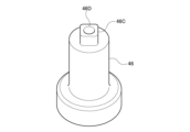
- FIG. 3 is a perspective view of a shear blade rotating shaft.
- FIG. 1 is a longitudinal cross-sectional view of a stirring device 10 according to an embodiment of the present invention.
- the stirring device 10 is installed in the vertical direction, which is the vertical direction or vertical direction in FIG. Use horizontal direction interchangeably.
- the present invention is also applicable to a stirring device 10 that is not installed vertically, and in such a case, the vertical direction, the vertical direction, and the vertical direction are different, and the horizontal direction, the horizontal direction, and the horizontal direction are different.
- the fluidizing blade rotating shaft 34 of the fluidizing blade 14 the shearing blade rotating shaft 46 of the shearing blade 16, the gate blade rotating shaft 52 of the gate blade 18, etc.
- each blade has a rotating axis
- the vertical direction, longitudinal direction, and vertical direction are also referred to as axial directions.
- the left-right direction, the lateral direction, and the horizontal direction determine the diameters of the stirring tank 12, the fluidizing blades 14, the shearing blades 16, the gate blades 18, etc., so the left-right direction, the lateral direction, and the horizontal direction are also referred to as radial directions.
- the stirring device 10 includes a stirring tank 12 that accommodates a fluid to be stirred, a fluidizing blade 14 as a rotary blade that can rotate around rotational shafts 34, 46, and 52 in the axial direction within the stirring tank 12, a shearing blade 16, A gate wing 18 is provided.
- the stirring tank 12 includes a cylindrical or tubular straight body part 20 that is provided above and extends in the axial direction, a bottom part 22 that is continuous with the straight body part 20 and provided below, and a bottom part 22 that is continuous with the straight body part 20. It has a top portion 24 provided above.
- the bottom portion 22 of the stirring tank 12 in this embodiment has a planar shape with the axial direction as the normal direction. As will be described later, forming the bottom portion 22 in a planar shape has the advantage that the distance in the axial direction from the shearing blade 16 can be reduced. It is applicable to the stirring tank 12 having the bottom 22 of any shape.
- the planar bottom portion 22 of the stirring tank 12 can be attached to a flange portion 21 formed to project in the radial direction at the bottom or lowest part of the cylindrical side wall 12a or the straight body portion 20 of the stirring tank 12. . That is, when assembling the stirring tank 12, the flat bottom portion 22 may be brought into contact with the flange portion 21 of the straight body portion 20 from below and fixed using a fixing device such as a screw. At this time, the shearing blades 16, shearing blade rotation shaft 46, shearing blade drive unit 47, etc., which will be described later, may be attached to the bottom part 22 in advance, or after the bottom part 22 is attached to the flange part 21, the shearing blades 16, the shearing blade drive part 47, etc.
- a blade rotation shaft 46, a shear blade drive unit 47, etc. may be attached to the bottom portion 22.
- the top part 24 of the stirring tank 12 in this embodiment has a planar shape with the axial direction as the normal direction.
- the planar top portion 24 of the stirring tank 12 can be attached to a flange portion 23 formed to project in the radial direction at the top or top of the cylindrical side wall 12a or the straight body portion 20 of the stirring tank 12. . That is, when assembling the stirring tank 12, the flat top portion 24 may be brought into contact with the flange portion 23 of the straight body portion 20 from above and fixed using a fixing device such as a screw.
- a fluidizing blade 14, a fluidizing blade rotating shaft 34 which will be described later, a fluidizing blade driving section (not shown) provided above in FIG.
- the gate blade drive unit, etc. may be attached to the top portion 24 in advance, or after the top portion 24 is attached to the flange portion 23, the fluidization blade 14, fluidization vane rotation shaft 34, fluidization vane drive unit, gate blade 18, and gate blade A rotating shaft 52, a gate blade drive unit, etc. may be attached to the top portion 24.
- the inner circumferential wall or side wall 12a of the straight body portion 20 of the stirring tank 12 has a circular cross section when viewed from above, and its diameter D is hereinafter also referred to as tank diameter D.
- tank diameter D the cross section of the straight body portion 20 and/or the stirring tank 12 when viewed from above may have any non-circular shape.
- the tank diameter D of the stirring tank 12 may be the diameter of the inscribed circle of the cross-sectional shape, the diameter of the circumscribed circle of the cross-sectional shape, or the average value or intermediate value thereof.
- At least a portion of the upper part of the straight body part 20 is opened so that a fluid to be stirred can be introduced thereinto, and can be closed with a lid or the like while the fluid is being stirred by the stirring device 10.
- the fluid to be stirred may be supplied into the stirring tank 12 from a fluid supply port such as a supply nozzle provided on the side surface of the straight body portion 20.
- the fluidizing blades 14, shearing blades 16, and gate blades 18 are each individually driven to rotate around a rotation axis in the vertical direction (vertical direction in FIG. 1) by a drive unit such as a motor or a speed reducer provided outside the stirring tank 12. be done.
- a drive unit such as a motor or a speed reducer provided outside the stirring tank 12.
- the flow blade rotation axis 34 of the flow blade 14, the shear blade rotation axis 46 of the shear blade 16, and the gate blade rotation axis 52 of the gate blade 18 do not have to be provided on the same straight line as in the example of FIG. Often, the respective directions may be different from each other.
- the rotation direction and rotation speed of the fluidizing blade 14, shearing blade 16, and gate blade 18 can be set or controlled independently of each other, and can be set or controlled independently of each other, depending on the capacity and shape of the stirring tank 12, the properties of the fluid in the stirring tank 12, and what should occur in the stirring tank 12. It is optimally set or controlled by taking into consideration various conditions such as the speed and phase of chemical reactions.
- the rotation speed of the shear blade 16, which is responsible for shearing and atomizing the fluid itself, fine particles in the fluid, aggregates thereof, etc., is higher than the rotation speed of the flow blade 14 and/or the gate blade 18, which is responsible for the flow of the fluid. big.
- the capacity of the stirring tank 12 is about 10 [l]
- the typical rotation speed of the fluidizing blade 14 is 20-30 [rpm]
- the rotation speed of the shearing blade 16 is about 1,200 [rpm].
- the capacity of the stirring tank 12 is about 1,000 [l]
- the typical rotational speed of the fluidizing blades 14 is 20-30[rpm]
- the rotational speed of the shearing blades 16 is 600-900[rpm]. ] is preferable.
- the rotational speed of the shearing blades 16 is preferably at least 20 times the rotational speed of the flow blades 14. Note that in order to obtain the same shearing performance as the large-diameter shearing blade 16 in this embodiment with the small-diameter disper blade in Patent Document 1, a rotation speed of about 3,600 [rpm] is required. According to the shearing blade 16 that can be made larger in diameter as described later, the rotational speed required to obtain the desired shearing performance or atomization performance is low, so by employing a low-power shearing blade drive unit 47, stirring can be improved. The device 10 can be made smaller or lower in cost.
- the fluidizing vane rotation shaft 34 of the fluidizing vane 14 is formed into a cylindrical or tubular shape, and the gate vane rotating shaft 52 of the gate vane 18 passes through the inside thereof.
- the fluidizing blade rotation shaft 34 of the fluidizing blade 14 and the gate blade rotating shaft 52 of the gate blade 18 extend from the top 24 of the stirring tank 12 into the stirring tank 12 .
- the fluidized vane rotation shaft 34 is rotationally driven by a fluidized vane drive unit (not shown) provided above in FIG. It is rotationally driven inside the rotating shaft 34.
- the flow blade drive unit and the gate blade drive unit be configured by different motors, it is preferable that they be configured integrally as one drive unit including the plurality of motors.
- the shear blade rotating shaft 46 of the shear blade 16 as a stirring blade extends into the stirring tank 12 from the bottom 22 of the stirring tank 12.
- the shearing blade rotation shaft 46 is rotationally driven by a shearing blade driving section 47 provided below in FIG.
- the drive unit below the stirring tank 12 that constitutes the shear blade drive section 47 is different from the drive unit above the stirring tank 12 that constitutes the aforementioned fluidization blade drive section and/or gate blade drive section.
- the fluidizing vane 14 is rotated around the fluidizing vane rotating shaft 34 by the fluidizing vane driving section to cause the fluid to flow within the stirring tank 12 .
- the fluidized vanes 14 in the illustrated example are a pair of ribbon vanes that are spirally formed around a vertical fluidized vane rotation axis 34 .
- the shape of the fluidizing blade 14 is not limited to a spiral shape or a ribbon shape, but in order to secure a sufficient space for installing a shearing blade 16, which will be described later, in an area facing the bottom 22 of the stirring tank 12, It is preferable to have a shape that has few portions that are close to each other. For this reason, the illustrated ribbon wing is preferable to the anchor wing having a shape that follows the bottom portion 22.
- the ribbon blades in the illustrated example face the bottom portion 22 at a location close to the side wall 12a of the stirring tank 12, but as will be described later, the shear blades 16 are located in the radially central region of the stirring tank 12 (shear blade rotation axis 46).
- the fluidizing blades 14 (ribbon blades) and shearing blades 16 (stirring blades) do not interfere with each other.
- the bottom 22 of the stirring tank 12 is often provided with a discharge port through which the fluid to be stirred settles and the fluid after stirring is discharged. Balance is required.
- the quality of the agitated fluid in the bottom 22 can be improved by configuring the flow blade 14 to rotate in the outer peripheral area of the bottom 22 and the shear blade 16 to rotate in the central area of the bottom 22. Furthermore, since the flow blades 14 are present only in the outer peripheral region of the bottom portion 22, the diameter of the shear blades 16 in the central region of the bottom portion 22 can be increased.
- the fluid vane 14 includes a plurality of band-shaped fluid vane bodies 26 (two in the example of FIG. 1) having a predetermined width, and a plurality of fluid vane bodies 26 that engage with the inner circumferential portion of each fluid vane body 26 at the upper and lower ends of each fluid vane body 26. (Two in the example of FIG. 1) support rods 28 are provided.
- the plurality of flow blade bodies 26 and the plurality of support rods 28 are integrated by welding or the like in a combined state as shown in the figure.
- Each support rod 28 is a rod-shaped member extending in the axial direction, and is supported by being engaged with the upper and lower ends of each fluid vane main body 26.
- each support rod 28 is engaged with a plurality of different fluid vane bodies 26, and each fluid vane body 26 is engaged with a plurality of different support bars 28.
- each support rod 28 may be provided on the same circumference as the two support rods 28 shown in FIG. 1 in a top view, and at intermediate positions therebetween. These two support rods 28 provided at the front and back of the plane of the drawing of FIG. maintains the desired spiral shape.
- the upper end of each support rod 28 is connected to a vertical fluidizing vane rotating shaft 34 .
- the fluid vane drive unit (not shown) rotationally drives the fluid vane rotating shaft 34
- the fluid vane 14 which is made up of the mutually connected support rod 28 and fluid vane main body 26, rotates integrally, and the above-mentioned downward induced flow is caused. It is formed.
- Each fluidized vane main body 26 is formed to rotate 180 degrees around the fluidized vane rotation axis 34 when viewed from above. Therefore, as described above, the upper end of each fluid vane main body 26 engages with one of the support rods 28, and the lower end of each fluid vane main body 26 engages with one of the support rods 28 when viewed from above.
- the other support rod 28 is engaged with the other support rod 28 in a point-symmetrical position (rotated position of 180 degrees) about the axis 34 .
- a gate blade 18 as an auxiliary blade or an internal blade having a smaller diameter than the flow blade 14 is installed on the radially central side or inside of the flow blade 14 .
- the gate blade 18 is rotationally driven around the gate blade rotating shaft 52 by a gate blade drive unit, and causes the fluid to flow in the stirring tank 12 inside the fluidizing blade 14 in a manner different from that of the fluidizing blade 14 .
- a shearing blade 16 described below is installed below the gate blade 18, the axial distance between the bottom 22 of the stirring tank 12 and the gate blade 18 (lower member 48D described later) is determined by the installation of the shearing blade 16. larger than the space or installation height. In other words, the space below the gate blades 18 can be utilized to the fullest by the shear blades 16.
- the gate blade 18 includes a rectangular frame-shaped gate blade main body 48 that is symmetrical about a vertical rotation axis (gate blade rotation axis 52), and a gate blade main body 48 that is connected to the upper part of the gate blade main body 48 and rotated by a gate blade drive unit (not shown).
- a driven axial gate blade rotation shaft 52 is provided.
- the gate wing main body 48 includes a radially upper member 48U, an axially left member 48L, an axially right member 48R, and a radially lower member 48D, which are each formed into a rod shape or columnar shape and are integrally formed in a rectangular shape. It has a standardized frame structure.
- the rotational direction and rotational speed of the gate blade 18 are arbitrary, typically the gate blade 18 rotates in the opposite direction to the flow blade 14, or rotates in the same direction as the flow blade 14 at a different speed or rotational speed. .
- the moving speed of the object to be stirred due to the rotation of the fluidizing blade 14 and the moving speed of the object to be stirred due to the rotation of the gate blade 18 can be changed. It makes a difference. Therefore, "co-rotation" in which the object to be stirred in the stirring tank 12 rotates together with the fluidizing blade 14 can be suppressed, and the object to be stirred in the stirring tank 12 can be made to flow efficiently. Furthermore, by appropriately setting the rotational direction and/or rotational speed of the gate blades 18, it is possible to generate a flow that causes the object to be stirred, which has been sheared by the shear blades 16 below the gate blades 18, to flow upward.
- the guided flow directed upward in the center of the stirring tank 12 generated by the gate blade 18 is changed by the fluidizing blade 14 into a guided flow directed downward along the side wall 12a of the stirring tank 12, and then flows back into the shear blade 16. Head towards. Since a circulating flow is thus formed between the fluidizing blades 14, the shearing blades 16, and the gate blades 18, the object to be stirred can be efficiently stirred.
- the shearing blade 16 as a stirring blade provided between the bottom 22 of the stirring tank 12 and the fluidizing blade 14 rotates around the shearing blade rotating shaft 46 by a shearing blade drive unit 47 to shear or shear the fluid in the stirring tank 12.
- the shearing blade 16 includes a pair of blade parts 17A and 17B (hereinafter also collectively referred to as the blade part 17) extending in the radial direction from the shearing blade rotating shaft 46 toward the side wall 12a of the stirring tank 12.
- the blade portion 17 In the radial direction (horizontal direction), the blade portion 17 is arranged in a central region on the center side or inside the lower end portion of the fluidizing blade 14 that rotates in the outer circumferential region of the stirring tank 12 or the bottom portion 22. Therefore, at least a portion (lower end portion) of the fluidizing blade 14 does not interfere with the blade portion 17 between the tip portion (the left end portion and the right end portion in FIG. 1) of the blade portion 17 and the side wall 12a of the stirring tank 12. It rotates without any problem. Further, the blade portion 17 is arranged between the upper gate blade 18 and the bottom portion 22 of the lower stirring tank 12 in the axial direction (vertical direction). That is, the blade portion 17 is arranged in the central region facing the bottom portion 22 of the stirring tank 12 .
- the shearing blade 16 including the blade part 17 extending in the radial direction approximately parallel to the bottom part 22 is connected to the upper gate blade 18 in the left-right direction. It can be efficiently or compactly arranged in a substantially rectangular parallelepiped region surrounded by the fluidizing blades 14 (lower end portion) and the bottom portion 22 of the stirring tank 12 below.
- FIG. 2 is a schematic side perspective view of the shear blade 16, and FIG. 3 is a top or bottom view of the shear blade 16.
- the shear blade 16 includes a cylindrical boss 161 whose height is in the axial direction (vertical direction in FIG. 2), and a pair of wing portions extending from the boss 161 in the radial direction (horizontal direction in FIGS. 2 and 3). 17A and 17B (wing parts 17).
- An axial attachment hole 46A into which the shear blade rotating shaft 46 is inserted and attached is provided in the radial center of the boss 161. As shown in FIG. 3, the attachment hole 46A is provided at the center of the recess 46B having a substantially rectangular or square cross section.
- a protrusion 46C (FIG. 4) that engages or fits therewith is provided at the upper end of the substantially cylindrical shear blade rotation shaft 46.
- the cross-sectional shape of the convex portion 46C is approximately rectangular or square, and is congruent with or slightly smaller in cross-sectional shape than the recessed portion 46B.
- a mounting hole 46D that communicates with the mounting hole 46A of the boss 161 is provided at the center of the convex portion 46C.
- the wing portion 17 is fixed to the boss 161 by, for example, welding. Note that the wing portion 17 may be directly fixed to the shear blade rotating shaft 46 by welding or the like, without using the boss 161.
- the normal direction of the stirring surface (surface) of each of the flat blades 17A, 17B is the axial direction of the shearing blade rotating shaft 46 (the vertical direction in FIG. 2) and the rotational direction of each of the blades 17A, 17B (the shearing blade It is inclined with respect to either direction (rotation direction around the rotation axis 46).
- a stirring blade or shearing blade including such a blade portion 17 is sometimes called an inclined paddle blade.
- the angle between the normal direction of the stirring surface of each blade part 17A, 17B and the axial direction of the shear blade rotating shaft 46 is 15 degrees or less (the angle formed with the rotation direction of each blade part 17A, 17B is 75 degrees or more) It is preferable that As a result, the stirring surfaces of the blades 17A, 17B are approximately parallel to the bottom 22 of the stirring tank 12 (forming an angle of 15 degrees or less), so the resistance that the rotating stirring surfaces receive from the fluid is reduced. Therefore, even if the diameter of the blade portion 17 is increased, it can be driven with relatively low power, and it is possible to prevent the shear blade drive portion 47 from increasing in size and cost. Furthermore, by inclining the wing section 17 as described above, the wing section 17 is less likely to idle even when using a fluid with high thixotropy or a fluid with low stringiness, so shearing efficiency or atomization efficiency is improved. .
- the non-disc-shaped shearing blade 16 or blade part 17 has a relatively small load power, so the blade diameter can be increased, and since it is light in weight, it is easy to balance the rotation. Therefore, the blade diameter in the extending direction of the blade part 17 (the radial distance between the left end of the blade part 17A and the right end of the blade part 17B in FIGS. 2 and 3) is 35% of the tank diameter D of the stirring tank 12. and 85%, preferably between 45% and 75%, more preferably between 50% and 70% of the tank diameter D of the stirring tank 12. Therefore, the shearing area can be made larger than that of conventional disk-shaped stirring blades, and shearing efficiency or atomization efficiency is improved.
- the shear blades 16 or the entire stirring device 10 of this embodiment are suitable for shearing and atomizing fluids with relatively high viscosity (at least fluids with a viscosity of 1,000 cP or more, for example, 10,000 cP or more).
- a high viscosity fluid include any fluid (oil, varnish, rubber, polymer solution, molten resin, etc.) containing fine particles such as carbon black and silica. Fine particles such as carbon black form aggregates in the fluid, but are efficiently made fine and/or dispersed by the shear blades 16 of this embodiment.
- the width w (Fig. 3) of the tip of the blade section 17 in the rotational direction is set to 5% or less of the tank diameter D of the stirring tank 12. It is preferable to do so.
- the blades 17 and the stirring tank 12 are The distance h (FIG. 1) of the bottom portion 22 is preferably 15% or less of the tank diameter D of the stirring tank 12.
- the shape of the stirring blade of the present invention is not limited to the shape of the shearing blade 16 illustrated in the embodiment.
- the stirring blade provided between the bottom of the stirring tank and the fluidizing blade has one or more blade portions extending from its rotation axis toward the side wall of the stirring tank. Any non-disk shape may be used.
- each device and each method described in the embodiments can be realized by hardware resources or software resources, or by cooperation of hardware resources and software resources.
- hardware resources for example, a processor, ROM, RAM, and various integrated circuits can be used.
- software resources for example, programs such as operating systems and applications can be used.
- the present invention relates to a stirring device and the like.
Landscapes
- Chemical & Material Sciences (AREA)
- Chemical Kinetics & Catalysis (AREA)
- Mixers Of The Rotary Stirring Type (AREA)
Priority Applications (5)
| Application Number | Priority Date | Filing Date | Title |
|---|---|---|---|
| CN202380051577.2A CN119486802A (zh) | 2022-07-29 | 2023-05-31 | 搅拌装置及搅拌方法 |
| JP2024536812A JPWO2024024262A1 (https=) | 2022-07-29 | 2023-05-31 | |
| DE112023003286.6T DE112023003286T5 (de) | 2022-07-29 | 2023-05-31 | Rührvorrichtung und rührverfahren |
| KR1020257000002A KR20250041609A (ko) | 2022-07-29 | 2023-05-31 | 교반장치, 교반방법 |
| US19/021,163 US20250153119A1 (en) | 2022-07-29 | 2025-01-15 | Stirring device and stirring method |
Applications Claiming Priority (2)
| Application Number | Priority Date | Filing Date | Title |
|---|---|---|---|
| JP2022121386 | 2022-07-29 | ||
| JP2022-121386 | 2022-07-29 |
Related Child Applications (1)
| Application Number | Title | Priority Date | Filing Date |
|---|---|---|---|
| US19/021,163 Continuation US20250153119A1 (en) | 2022-07-29 | 2025-01-15 | Stirring device and stirring method |
Publications (1)
| Publication Number | Publication Date |
|---|---|
| WO2024024262A1 true WO2024024262A1 (ja) | 2024-02-01 |
Family
ID=89706037
Family Applications (1)
| Application Number | Title | Priority Date | Filing Date |
|---|---|---|---|
| PCT/JP2023/020292 Ceased WO2024024262A1 (ja) | 2022-07-29 | 2023-05-31 | 撹拌装置、撹拌方法 |
Country Status (7)
| Country | Link |
|---|---|
| US (1) | US20250153119A1 (https=) |
| JP (1) | JPWO2024024262A1 (https=) |
| KR (1) | KR20250041609A (https=) |
| CN (1) | CN119486802A (https=) |
| DE (1) | DE112023003286T5 (https=) |
| TW (1) | TW202404695A (https=) |
| WO (1) | WO2024024262A1 (https=) |
Families Citing this family (3)
| Publication number | Priority date | Publication date | Assignee | Title |
|---|---|---|---|---|
| JP7733449B2 (ja) * | 2021-02-15 | 2025-09-03 | 住友重機械プロセス機器株式会社 | 撹拌装置 |
| CN120459849B (zh) * | 2025-07-10 | 2025-10-03 | 程喜 | 一种大漆的加工工艺及加工设备 |
| CN120939797B (zh) * | 2025-10-15 | 2026-02-24 | 福建叁芯科技集团有限公司 | 一种高沸点低冰点冷却液均质设备及其制备方法 |
Citations (3)
| Publication number | Priority date | Publication date | Assignee | Title |
|---|---|---|---|---|
| JPS51134872U (https=) * | 1975-04-22 | 1976-10-30 | ||
| JPH01179731U (https=) * | 1988-06-08 | 1989-12-25 | ||
| JP2008012449A (ja) * | 2006-07-06 | 2008-01-24 | Akira Kiko Kk | 攪拌造粒装置 |
Family Cites Families (1)
| Publication number | Priority date | Publication date | Assignee | Title |
|---|---|---|---|---|
| EP3318317B1 (en) | 2015-07-01 | 2022-05-11 | Sumitomo Heavy Industries Process Equipment Co., Ltd. | Stirring device |
-
2023
- 2023-05-31 JP JP2024536812A patent/JPWO2024024262A1/ja active Pending
- 2023-05-31 KR KR1020257000002A patent/KR20250041609A/ko active Pending
- 2023-05-31 CN CN202380051577.2A patent/CN119486802A/zh active Pending
- 2023-05-31 DE DE112023003286.6T patent/DE112023003286T5/de active Pending
- 2023-05-31 WO PCT/JP2023/020292 patent/WO2024024262A1/ja not_active Ceased
- 2023-06-28 TW TW112124036A patent/TW202404695A/zh unknown
-
2025
- 2025-01-15 US US19/021,163 patent/US20250153119A1/en active Pending
Patent Citations (3)
| Publication number | Priority date | Publication date | Assignee | Title |
|---|---|---|---|---|
| JPS51134872U (https=) * | 1975-04-22 | 1976-10-30 | ||
| JPH01179731U (https=) * | 1988-06-08 | 1989-12-25 | ||
| JP2008012449A (ja) * | 2006-07-06 | 2008-01-24 | Akira Kiko Kk | 攪拌造粒装置 |
Also Published As
| Publication number | Publication date |
|---|---|
| JPWO2024024262A1 (https=) | 2024-02-01 |
| CN119486802A (zh) | 2025-02-18 |
| US20250153119A1 (en) | 2025-05-15 |
| DE112023003286T5 (de) | 2025-05-22 |
| TW202404695A (zh) | 2024-02-01 |
| KR20250041609A (ko) | 2025-03-25 |
Similar Documents
| Publication | Publication Date | Title |
|---|---|---|
| WO2024024262A1 (ja) | 撹拌装置、撹拌方法 | |
| KR102153523B1 (ko) | 고점도 유체 교반용 임펠러 | |
| JPWO2017002905A1 (ja) | 撹拌装置 | |
| CN102271794A (zh) | 凸缘式搅拌器 | |
| KR20240058006A (ko) | 교반용 임펠러 | |
| JP7582832B2 (ja) | 撹拌装置 | |
| CN215428731U (zh) | 一种化工用催化剂颗粒混合设备 | |
| JP2010155220A (ja) | 撹拌装置 | |
| CN202289947U (zh) | 无动力管道搅拌器 | |
| CN114177807A (zh) | 搅拌装置 | |
| CN119281193A (zh) | 循环制浆设备 | |
| JP4979158B2 (ja) | 攪拌装置 | |
| JP2015085218A (ja) | 撹拌装置 | |
| CN117919988A (zh) | 搅拌用叶轮 | |
| JP2015213886A (ja) | 撹拌装置 | |
| KR20240166906A (ko) | 교반 기기 | |
| CN212130438U (zh) | 一种固井用振动器 | |
| CN204073996U (zh) | 一种宽螺带锯齿搅拌器 | |
| CN104043371B (zh) | 一种离心分散器 | |
| CN223464748U (zh) | 循环制浆设备 | |
| US20110261644A1 (en) | Mixer flow direction apparatus and method | |
| CN212167163U (zh) | 一种用于水处理的搅拌机 | |
| JPH0356132A (ja) | 撹拌装置 | |
| JPS643476Y2 (https=) | ||
| CN223818501U (zh) | 套式搅拌桨及搅拌设备 |
Legal Events
| Date | Code | Title | Description |
|---|---|---|---|
| 121 | Ep: the epo has been informed by wipo that ep was designated in this application |
Ref document number: 23844525 Country of ref document: EP Kind code of ref document: A1 |
|
| WWE | Wipo information: entry into national phase |
Ref document number: 2024536812 Country of ref document: JP |
|
| WWE | Wipo information: entry into national phase |
Ref document number: 202380051577.2 Country of ref document: CN |
|
| WWP | Wipo information: published in national office |
Ref document number: 202380051577.2 Country of ref document: CN |
|
| WWE | Wipo information: entry into national phase |
Ref document number: 112023003286 Country of ref document: DE |
|
| WWP | Wipo information: published in national office |
Ref document number: 1020257000002 Country of ref document: KR |
|
| WWP | Wipo information: published in national office |
Ref document number: 112023003286 Country of ref document: DE |
|
| 122 | Ep: pct application non-entry in european phase |
Ref document number: 23844525 Country of ref document: EP Kind code of ref document: A1 |