WO2024024102A1 - 計算機システム、タスクスケジューラ装置、待ちプロセス起床方法およびプログラム - Google Patents
計算機システム、タスクスケジューラ装置、待ちプロセス起床方法およびプログラム Download PDFInfo
- Publication number
- WO2024024102A1 WO2024024102A1 PCT/JP2022/029347 JP2022029347W WO2024024102A1 WO 2024024102 A1 WO2024024102 A1 WO 2024024102A1 JP 2022029347 W JP2022029347 W JP 2022029347W WO 2024024102 A1 WO2024024102 A1 WO 2024024102A1
- Authority
- WO
- WIPO (PCT)
- Prior art keywords
- standby
- idle
- task
- pseudo
- state
- Prior art date
- Legal status (The legal status is an assumption and is not a legal conclusion. Google has not performed a legal analysis and makes no representation as to the accuracy of the status listed.)
- Ceased
Links
Images












Classifications
-
- G—PHYSICS
- G06—COMPUTING OR CALCULATING; COUNTING
- G06F—ELECTRIC DIGITAL DATA PROCESSING
- G06F9/00—Arrangements for program control, e.g. control units
- G06F9/06—Arrangements for program control, e.g. control units using stored programs, i.e. using an internal store of processing equipment to receive or retain programs
- G06F9/46—Multiprogramming arrangements
- G06F9/48—Program initiating; Program switching, e.g. by interrupt
- G06F9/4806—Task transfer initiation or dispatching
- G06F9/4843—Task transfer initiation or dispatching by program, e.g. task dispatcher, supervisor, operating system
- G06F9/485—Task life-cycle, e.g. stopping, restarting, resuming execution
-
- G—PHYSICS
- G06—COMPUTING OR CALCULATING; COUNTING
- G06F—ELECTRIC DIGITAL DATA PROCESSING
- G06F9/00—Arrangements for program control, e.g. control units
- G06F9/06—Arrangements for program control, e.g. control units using stored programs, i.e. using an internal store of processing equipment to receive or retain programs
- G06F9/46—Multiprogramming arrangements
- G06F9/48—Program initiating; Program switching, e.g. by interrupt
- G06F9/4806—Task transfer initiation or dispatching
- G06F9/4843—Task transfer initiation or dispatching by program, e.g. task dispatcher, supervisor, operating system
- G06F9/4881—Scheduling strategies for dispatcher, e.g. round robin, multi-level priority queues
-
- G—PHYSICS
- G06—COMPUTING OR CALCULATING; COUNTING
- G06F—ELECTRIC DIGITAL DATA PROCESSING
- G06F9/00—Arrangements for program control, e.g. control units
- G06F9/06—Arrangements for program control, e.g. control units using stored programs, i.e. using an internal store of processing equipment to receive or retain programs
- G06F9/46—Multiprogramming arrangements
- G06F9/48—Program initiating; Program switching, e.g. by interrupt
- G06F9/4806—Task transfer initiation or dispatching
- G06F9/4843—Task transfer initiation or dispatching by program, e.g. task dispatcher, supervisor, operating system
- G06F9/4881—Scheduling strategies for dispatcher, e.g. round robin, multi-level priority queues
- G06F9/4893—Scheduling strategies for dispatcher, e.g. round robin, multi-level priority queues taking into account power or heat criteria
-
- Y—GENERAL TAGGING OF NEW TECHNOLOGICAL DEVELOPMENTS; GENERAL TAGGING OF CROSS-SECTIONAL TECHNOLOGIES SPANNING OVER SEVERAL SECTIONS OF THE IPC; TECHNICAL SUBJECTS COVERED BY FORMER USPC CROSS-REFERENCE ART COLLECTIONS [XRACs] AND DIGESTS
- Y02—TECHNOLOGIES OR APPLICATIONS FOR MITIGATION OR ADAPTATION AGAINST CLIMATE CHANGE
- Y02D—CLIMATE CHANGE MITIGATION TECHNOLOGIES IN INFORMATION AND COMMUNICATION TECHNOLOGIES [ICT], I.E. INFORMATION AND COMMUNICATION TECHNOLOGIES AIMING AT THE REDUCTION OF THEIR OWN ENERGY USE
- Y02D10/00—Energy efficient computing, e.g. low power processors, power management or thermal management
Definitions
- the present invention relates to a computer system, a task scheduler device, a waiting process wake-up method, and a program.
- a computer (hereinafter referred to as a server) is equipped with a general-purpose processor (CPU), and if a process running on the CPU does not need to be constantly running, the process is stopped and separated when necessary. A process may be returned to a running state by sending a notification from that process.
- CPU general-purpose processor
- FIG. 19 is a diagram showing inter-process communication within the server using the polling method.
- an application hereinafter referred to as "APL" [A: waiting side] 1 requests APL [B: notifying side] 1 to process a task (S1).
- APL [A: waiting side] 1 requests the processing result by polling (S2).
- APL [B: notification side] 1 executes the task processing requested by APL [A: waiting side] 1 (S3).
- APL [B: notification side] 1 sends the processing result to APL [A: waiting side] 1 in response to the polling request (S4).
- APL [A: Waiting side] 1 executes the following process (S5).
- FIG. 20 is a diagram showing inter-process communication within the server using the notification method. The same steps as those in FIG. 19 are given the same step numbers. As shown in FIG. 20, APL [A: waiting side] 1 requests APL [B: notifying side] 1 to process a task (S1). APL [A: waiting side] 1 performs sleep control and enters a sleep state (S6).
- APL [B: notification side] 1 executes the task processing requested by APL [A: waiting side] 1 (S3).
- APL [B: notification side] 1 notifies APL [A: waiting side] 1 of the completion of the process (S7).
- APL [A: Waiting side] 1 receives the processing completion notification from APL [B: Notifying side] 1 (S7), wakes up from the sleep state, and requests the processing result from APL [B: Notifying side] 1. (S8).
- APL [B: notification side] 1 receives the result request from APL [A: wait side] 1, and sends the processing result to APL [A: wait side] 1 (S4).
- APL [A: Waiting side] 1 executes the following process (S5).
- a process A requests another process B to process a task, and polls until the task process in process B is completed to see if it has been completed.
- Process A is in operation and power consumption increases.
- sleep control is adopted in which process A enters a sleep state after requesting process B to process a task. Since process A enters the sleep state, power consumption can be reduced.
- process B notifies process A of the completion of processing, and process A that receives the notification wakes up from sleep and requests process B to complete the task. However, since process A wakes up from sleep, a delay time occurs for recovery.
- FIG. 21 is a diagram showing a notification system using eventfd+epoll_wait.
- the server includes hardware (HW) 10, an OS 20, a standby process [core #n] 30, and a notification process [core #m] 32 in the user space.
- the standby process [core #n] 30 is "process A" of APL [A: waiting side] 1
- the notification process [core #m] 32 is "process A" of APL [B: notifying side] 1.
- Process B is a diagram showing a notification system using eventfd+epoll_wait.
- the hardware (HW) 10 includes a CPU 11.
- the standby process [core #n] 30 has a standby function 31 .
- the OS 20 includes an event monitoring instance 21 and a notification FD (File Descriptor) 22.
- the notification FD 22 is an integer value that specifies a file when requesting access to the OS 20. When operating a file from a program, it is assigned to identify the file to be operated (hereinafter, ".” represents "and").
- a standby process 30 (“process A”) creates an event monitoring instance 21 (eventpoll). 2.
- the standby process 30 creates a notification FD 22 (eventfd), which is an FD used for notifications, and performs the above 1. to the event monitoring instance 21 of. 3.
- the standby process 30 transfers the notification FD 22 to the notification process 32 ("process B").
- process A creates an event monitoring instance 21
- process B creates a notification FD 22
- process B the notification process 32
- the standby process 30 performs the above 1. It specifies the event monitoring instance 21, issues the wait function 31 (epoll_wait), and enters a blocking (sleep) state. When the standby function 31 (epoll_wait) is issued, the standby process 30 enters a sleep state until an event is issued. The standby process 30 itself goes into a sleep state, but if there is no other process on the corresponding CPU core, which corresponds to an idle state, when the standby process 30 goes into a sleep state, An idle task will appear. This idle task is a state in which the CPU core does nothing, but automatically appears when there are no processes.
- the notification process 32 detects the occurrence of an event and writes it to the notification FD 22. 7. When writing is performed to the notification FD 22, an event monitoring callback is executed (occurs). 8. When an event monitoring callback occurs, an instruction is sent to the standby function 31 that is waiting for the event monitoring instance 21. The designated standby function 31 detects the event and wakes up. 9. The standby process 30 that called the standby function 31 resumes processing. In addition, above 2. In some cases, the notification FD creation is executed on the notification process 32 side.
- FIG. 22 is a diagram illustrating the standby process of the existing technology described in Non-Patent Document 1.
- the standby process 40 has a standby section 41 and a sleep section 42
- the idle process 50 (idle task) has an idle section 51.
- the OS kernel 60 includes a scheduler 61 and a C-state control unit 62 (C-state will be described later).
- the idle process 50 disappears when another process (thread) exists on the CPU core.
- the standby unit 41 calls the sleep unit 42, and the process (standby process 40) enters the standby state.
- the scheduler 61 calls the process having the idle part 51 if there is no other process in an executable state.
- the idle unit 51 uses the C-state control unit 62 to transition the CPU to a sleep state or turn off the power.
- Context switching refers to the process of saving/restoring the state (context) of a CPU (hereinafter, "/" represents "or") so that multiple processes can share one CPU.
- the C-state return time is determined by the kernel.
- the kernel determines the depth of the C-state based on the idle time estimated by the C-state control unit 62. There is a time required to return from the corresponding C-state (Non-Patent Document 2).
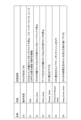
- FIG. 23 is a diagram showing an example of C-state states in a table. Note that since the state definition differs depending on the CPU hardware, FIG. 23 is just a reference example. As shown in FIG. 23, the CPUidle state has grades C0 to C6, and as the time when the CPU is not loaded increases, the state transitions to a deep sleep state. A deep sleep state consumes less CPU power, but on the other hand, it lengthens the time it takes to return, which may pose a problem in terms of low latency.
- C-state differs depending on the CPU hardware. For example, there are variations such as a model without C4 or C5, and a model in which the state following C1 is C1E. As the state becomes deeper, the power saving effect increases, but the time required to return from the idle state also increases.
- the depth to which the CPUidle state transitions is controlled by the CPU hardware and depends on the CPU product (in many cases, it cannot be controlled from software such as the kernel).
- FIG. 24 is a diagram illustrating problems with existing technology.
- the lower part of FIG. 24 shows the schedule of the standby process (core #n), and the upper part of FIG. 24 shows the schedule of the notification process (core #m).
- an idle task may be scheduled for the corresponding CPU core.
- the event receiver (core #n) transitions to the idle task 76 by a context switch (reference numeral a in FIG. 24) after executing the standby process processing 71 and the standby function 72.
- the idle task 76 appears if the corresponding CPU core is in the idle state with no other processes running on it.
- the CPU core (event receiver (core #n)) falls into a deep sleep state (CPU idle) in stages, making it possible to reduce power consumption.
- event sender (core #m) is 5. When an event occurs, 6. By writing to the notification FD 74, 7. The event monitoring callback 75 is executed, and the event sender (core #m) issues an inter-processor interrupt (reference numeral b in FIG. 24) to the event receiver (core #n).
- step 9 When the standby function wakes up in step 9, the idle task 76 is scheduled again, and then the standby function is scheduled via a context switch (reference numeral c in FIG. 24).9. The standby process processing is resumed (number 78 in FIG. 24).
- a context switch generally switches between operating in Kernel space and operating in User space. This context switch from the idle task 76 to the standby function wake-up 77 (sign c in FIG. 24) causes a large delay (marked with ⁇ d in FIG. 24). That is, a context switch time occurs when switching to the standby function, resulting in a large delay.
- FIG. 25 is a diagram showing a C-state transition image of a CPU core used for calculations superimposed on the schedule of FIG. 24.
- the CPU core is in a deep sleep state (CPUidle state: grade C6), and the delay time until recovery after a task is generated (code e in Figure 25) is prolonged. do.
- the CPU drops to a deep idle state, it takes a long time to recover, which impairs real-time performance.
- the base station (BBU) takes measures such as disabling the C-state or introducing settings that limit the transition of the idle state to a limited depth such as C1. In other words, tuning may be performed in favor of real-time performance at the expense of power saving.
- the present invention was made in view of this background, and an object of the present invention is to reduce the time required for a standby process to wake up after an event occurs.
- a computer system has a processor consisting of multiple cores and runs a process that executes a predetermined instruction using the time on the processor, and the process runs until notified.
- a standby process that enters a standby state and wakes up and resumes operation when there is a notification, and a notification process that sends a notification to wake up the standby process when an event occurs, and the standby process is set to a standby state.
- the computer system is characterized in that it has a pseudo-idle task that continues to occupy the processor when the computer is running.
- FIG. 1 is a schematic configuration diagram of a computer system according to an embodiment of the present invention.
- FIG. 2 is a diagram illustrating context switch elimination (feature ⁇ 1>) of the computer system according to the embodiment of the present invention.
- FIG. 2 is a diagram showing a C-state transition image of a CPU core superimposed on a schedule of a CPU core used for calculations in a computer system according to an embodiment of the present invention.
- FIG. 6 is a diagram showing the behavior of the standby process at ⁇ at the start of standby>, ⁇ during standby>, and ⁇ at the time of event occurrence> in a comparative example of the computer system according to the embodiment of the present invention.
- FIG. 1 is a schematic configuration diagram of a computer system according to an embodiment of the present invention.
- FIG. 2 is a diagram illustrating context switch elimination (feature ⁇ 1>) of the computer system according to the embodiment of the present invention.
- FIG. 2 is a diagram showing a C-state transition image of a CPU core
- FIG. 3 is a diagram illustrating the behavior of the standby process of the computer system according to the embodiment of the present invention ⁇ at the start of standby>, ⁇ during standby>, and ⁇ at the time of occurrence of an event>.
- FIG. 6 is a diagram showing the behavior of the standby process at ⁇ at the start of standby>, ⁇ during standby>, and ⁇ at the time of event occurrence> in a comparative example of the computer system according to the embodiment of the present invention.
- FIG. 3 is a diagram illustrating the behavior of the standby process of the computer system according to the embodiment of the present invention ⁇ at the start of standby>, ⁇ during standby>, and ⁇ at the time of occurrence of an event>.
- FIG. 2 is a diagram showing an implementation image in a comparative example of a computer system according to an embodiment of the present invention.
- 1 is a diagram showing an implementation image of a computer system according to an embodiment of the present invention.
- FIG. 1 is a diagram illustrating an application range 1 of a computer system according to an embodiment of the present invention.
- FIG. 2 is a diagram illustrating a second scope of application of the computer system according to the embodiment of the present invention. This is a sequence in a case where a pseudo idle function is required before an event occurs in a computer system according to an embodiment of the present invention.
- This is a sequence in a case where the pseudo idle function before an event occurs in the computer system according to the embodiment of the present invention is unnecessary.
- FIG. 7 is a flowchart for executing a pseudo-idle function in a pseudo-idle determination unit of a computer system according to an embodiment of the present invention. It is a flowchart of the maximum return time determination in the return time determination part of the computer system based on embodiment of this invention.
- FIG. 3 is a diagram illustrating an example of the operation when the maximum recovery time determination process of the computer system according to the embodiment of the present invention is executed.
- FIG. 1 is a hardware configuration diagram showing an example of a computer that implements the functions of a task scheduler device of a computer system according to an embodiment of the present invention.
- FIG. 2 is a diagram illustrating inter-process communication within a server using a polling method.
- FIG. 2 is a diagram illustrating inter-process communication within a server using a notification method. It is a diagram showing a notification system using eventfd+epoll_wait.
- FIG. 2 is a diagram illustrating a standby process of existing technology.
- FIG. 3 is a diagram illustrating an example of C-state states in a table form.
- FIG. 2 is a diagram illustrating problems with existing technology.
- 25 is a diagram showing a C-state transition image of a CPU core used for calculations superimposed on the schedule of FIG. 24.
- FIG. 1 is a schematic configuration diagram of a computer system according to an embodiment of the present invention. Components that are the same as those in FIG. 22 are given the same reference numerals.
- This embodiment is an example in which the present invention is applied to a CPU as a computer system.
- the present invention is also applicable to processors such as GPUs (Graphic Processing Units), FPGAs (Field Programmable Gate Arrays), and ASICs (Application Specific Integrated Circuits), if they have an idle state function.
- GPUs Graphic Processing Units
- FPGAs Field Programmable Gate Arrays
- ASICs Application Specific Integrated Circuits
- the computer system 1000 includes a kernel 60, CPU cores (core #m, core #n, core #x) 80, a notification process 90, an idle process 50, and a task scheduler device 100.
- the kernel 60 includes a scheduler 61, a C-state control unit 62, an fd (file descriptor) 63 such as eventfd, and a socket (communication socket) 64 such as Unix Domain Socket.
- the idle process 50 has an idle section 51.
- the idle process 50 allows other processes (threads) to use the corresponding CPU core while it is on standby.
- the computer system 1000 has a processor consisting of a plurality of cores, and a process that executes a predetermined instruction using the time on the processor runs, and the process is in a waiting state until a notification is received.
- a standby process 101 that wakes up and resumes operation when an event occurs
- a notification process 90 that sends a notification to wake up the standby process when an event occurs
- an idle process 50 that occurs when there is no process on the processor and does not execute anything.
- the task scheduler device 100 includes a standby section 110, a pseudo-idle section 120, a pseudo-idle judgment section 130, a return time determination section 140 (return time control section), and a return time setting section 150 (return time control section). , is provided.
- the standby unit 110 and the pseudo-idle unit 120 constitute the standby process 101, and cooperate with the idle unit 51 of the idle process 50 (idle task).
- the pseudo idle determining section 130, the return time determining section 140, and the return time setting section 150 constitute the management section 102.
- the standby process 101 remains in a standby state until a notification is received, and when there is a notification, it wakes up and resumes operation.
- the standby unit 110 maintains an executable state.
- the standby unit 110 receives a pseudo-idle function request from the pseudo-idle determining unit 130, and performs a stand-by setting and an executable state setting. Specifically, in response to an instruction from the pseudo-idle determination unit 130, the pseudo-idle unit 120 is executed or a context switch is performed to an idle process having an idle function.
- the pseudo idle unit 120 maintains a sleep (NOP) state in which it does not execute anything.
- the pseudo idle unit 120 calls and executes the C-state control unit 62 that controls the operating state of the CPU instead of the idle unit 51.
- the pseudo-idle unit 120 has a pseudo-idle task 103 (FIGS. 5 and 7) in which the stand-by process 101 continues to monopolize the processor when in the stand-by state.
- the Kernel scheduler gives execution time to the standby process 101 when an event occurs. Since the pseudo idle task 103 that is being executed immediately before is executed as an extension of the standby process, a context switch accompanying process switching can be eliminated.
- the pseudo-idle determining unit 130 determines whether to execute the pseudo-idle unit 120 (pseudo-idle task) based on the process occurrence state on the same processor and/or the delay time requirements, and sends the pseudo-idle task to the standby unit 110. Instruct.
- the reason why it is necessary to determine whether to execute the pseudo-idle section 120 is that, as will be described later in FIG. This is because it is not effective in eliminating context switches by running , and it may also have an impact on other processes, such as increasing processing delays.
- the return time determining unit 140 determines the return time corresponding to the C-state in which the pseudo idle unit 120 can fall at maximum, based on the delay time requirements and the current C-state.
- the return time determining section 140 notifies the return time setting section 150 of the maximum return time.
- the return time setting unit 150 sets the maximum return time in the C-state control unit 62 using the maximum return time from the return time determining unit 140.
- the return time setting unit 150 returns to the original maximum return time again after the pseudo idle unit 120 ends.
- the return time determining section 140 and the return time setting section 150 described above constitute a return time setting section that sets the return time until the pseudo idle task 103 returns after task generation.
- This return time control unit is a functional unit that overwrites the determined return time with the maximum return time and shortens the maximum return time to prevent transition to a deep sleep state.
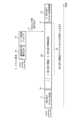
- FIG. 2 is a diagram illustrating context switch exclusion (feature ⁇ 1>). The same processes as in FIG. 24 are given the same reference numerals. The lower part of FIG. 2 shows the schedule of the event receiver (core #n), and the upper part of FIG. 2 shows the schedule of the event sender (core #m). Below 1. ⁇ 3. Assume that has been executed at initialization. 1. Event monitoring instance creation 2. Create notification FD/register event monitoring instance 3. Notification FD transfer
- the event receiver executes the process without transitioning to the idle task (without generating a context switch) (symbol aa in FIG. 2); 4. Standby function ⁇ 8.
- the standby function wakes up 201. That is, in the standby function/standby function wake-up 201, 4.
- the standby function behaves in the same way as an idle task (symbol bb in FIG. 2).
- event sender (core #m) is 5. When an event occurs, 6. By writing to the notification FD 74, 7. The event monitoring callback 75 is executed, and the event sender (core #m) issues an inter-processor interrupt (reference numeral b in FIG. 2) to the event receiver (core #n).
- the standby function behaves the same as an idle task. 9. When the standby function wakes up, the idle task is not scheduled, so a context switch (symbol cc in FIG. 2) does not occur. The standby process process resumes 78.
- Feature ⁇ 2> Specify the return time of the pseudo idle task Specify the maximum return time of the pseudo idle task and control it so that it does not fall into a deep sleep state.
- the return time determined by the OS governor is overwritten with the maximum return time to shorten the maximum return time.
- ⁇ Requirement 1 Reduction of notification time>.
- ⁇ Requirement 2 Power saving>.
- FIG. 3 is a diagram showing a C-state transition image of a CPU core used for calculations superimposed on the schedule of FIG. 2.
- the same processes as in FIG. 25 are given the same reference numerals.
- the maximum return time (sign ee in FIG. 3) from task generation (code dd in FIG. 3) to recovery is specified.
- the reason why such a maximum return time can be specified is that a standby function/standby function wake-up 201 is provided so that the stand-by function behaves in the same way as an idle task, and the schedule of this stand-by function/standby function wake-up 201 is flexible.
- FIG. 4 is a diagram showing the behavior of the standby process at ⁇ at the start of standby>, ⁇ during standby>, and ⁇ at the time of event occurrence> in the comparative example.
- the same configurations and processes as in FIG. 1 are given the same reference numerals.
- the server includes a CPU core 80 (event receiver (core #n)) and a CPU core 80 (event sender (core #m)).
- the standby process 91 is in the task queue 85 on the CPU core 80 (core #n).
- the so-called waiting state means that the waiting process 91 enters the waiting queue 86 on the CPU core 80 (core #n).
- the standby process 91 leaves the task queue 85 (arrow f in FIG. 4), enters the wait queue 86 on the right side of FIG. 4, and enters the wait state.
- the idle task 92 is on the CPU core 80 (core #n). Appear.
- This idle task 92 is a process (task) that automatically appears so that the task queue 85 does not become empty.
- the standby process 91 receives a notification from the notification process 90 via fd63 and socket64 of the kernel 60 (FIG. 1), and returns to the task queue 85 in the center of FIG. 4 (arrow in FIG. 4). g). When the standby process 91 returns to the task queue 85, a context switch between the idle task 92 and the standby process 91 occurs (reference numeral c in FIG. 24).
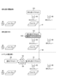
- FIG. 5 is a diagram showing the behavior of the standby process at ⁇ at the start of standby>, ⁇ during standby>, and ⁇ at the time of occurrence of an event> in this embodiment.
- Components and processes that are the same as those in FIGS. 1 and 4 are designated by the same reference numerals.
- the server includes a CPU core 80 (event receiver (core #n)) and a CPU core 80 (event sender (core #m)).
- the standby process 101 is in the task queue 85 on the CPU core 80 (core #n).
- the behavior of the standby process is the same in this embodiment and the comparative example.
- the standby process 101 includes a standby section 110 and a pseudo idle section 120 (FIG. 1). That is, the standby process 101 further introduces a pseudo idle section 120 (pseudo idle task 103) into the standby process 91 of FIG. Since the pseudo idle task 103 does not generate an idle task 92, it continues to exclusively occupy the CPU core 80 (core #n) so as to prevent the standby process 101 from entering the task queue 85. That is, by introducing the pseudo-idle task 103, the CPU core continues to be exclusively occupied without surrendering the CPU core to another process. More specifically, monopolizing the CPU core means continuing to monopolize the CPU time without giving up. Specifically, the pseudo idle task 103 issues an epoll, but continues to monopolize the CPU time without yielding it to other processes (threads).
- the standby process 101 continues to remain in the task queue 85. That is, in the comparative example shown in FIG. 4, during standby, the standby process 91 exits the task queue 85 and enters the wait queue 86 to be in a standby state. In contrast, in the present embodiment, although the pseudo idle task 103 issues an epoll, it continues to monopolize the CPU time without giving up the CPU time to other processes (threads), so that the standby process 101 continues to remain in the task queue.
- the pseudo idle task 103 continues to exclusively occupy the CPU core 80 (core #n), so the standby process 101 can continue to remain in the task queue 85, and no context switch occurs.
- the presence of the idle task 92 in the task queue 85 enabled the CPU core 80 (core #n) to transition to the idle state.
- the pseudo idle task 103 of this embodiment operates in the same way as the idle task 92.
- the pseudo idle task 103 is a task that basically does nothing like the idle task 92, but since there is a pseudo idle task 103 that operates in the same way as the idle task 92, the pseudo idle task 103 can cause the CPU to sleep. (NOP) instruction can be executed. This makes it possible to reduce the CPU cycle and suppress the power consumption of the corresponding CPU core.
- the standby process 101 receives a notification from the notification process 90 via the fd 63 and socket 64 of the kernel 60 (FIG. 1). Since the standby process 101 continues to remain in the task queue 85 (symbol gg in FIG. 5), it is already in the task queue 85 when it receives a notification when event issuance is detected in the kernel mode. Therefore, no context switch occurs (symbol cc in FIG. 2).
- FIG. 6 is a diagram showing the behavior of the standby process at ⁇ at the start of standby>, ⁇ during standby>, and ⁇ at the time of event occurrence> in the comparative example. Components and processes that are the same as those in FIG. 4 are given the same reference numerals. It is assumed that the task scheduler device 100 allocates CPU execution time to processes in the task queue 85 that are in an executable state (TASK_RUNNING).
- the task scheduler device 100 gives execution time to the standby process (reference numeral h in FIG. 6).
- the task scheduler device 100 generates an idle task 92 when the task queue 85 becomes empty, and gives execution time to the idle task 92. At this time, a context switch occurs (symbol i in FIG. 6). Also, during standby, the standby process 91 leaves the task queue 85 (arrow j in FIG. 6), enters the wait queue 86, and enters the wait state.
- the task scheduler device 100 gives execution time to the standby process 91. At this time, a context switch occurs (symbol k in FIG. 6). Further, the standby process 91 returns to the task queue 85 in the center of FIG. 6 again (arrow l in FIG. 4).
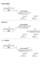
- FIG. 7 is a diagram showing the behavior of the standby process at ⁇ at the start of standby>, ⁇ during standby>, and ⁇ at the time of occurrence of an event> in this embodiment. Components and processes that are the same as those in FIG. 5 are given the same reference numerals. It is assumed that the task scheduler device 100 allocates CPU execution time to processes in the task queue 85 that are in an executable state (TASK_RUNNING).
- the task scheduler device 100 gives execution time to the standby process 101 (reference hh in FIG. 7).
- the task scheduler device 100 gives execution time to the standby process 101 (reference numeral ii in FIG. 7). That is, since the pseudo idle task 103 continues to exclusively occupy the CPU core 80 (core #n) (see ⁇ Standby> in FIG. 5), the standby process 101 can continue to remain in the task queue 85, and the context switch is not performed. Does not occur.
- the task scheduler device 100 gives execution time to the standby process 101 (symbol jj in FIG. 7).
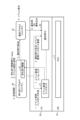
- FIG. 8 is a diagram showing an implementation image in a comparative example.
- driver/hardware has a cpuidle driver (ACPI/intel_idle) 306.
- the kernel includes a task scheduler device 100, a sysfs 303, a cpuidle governor 304, and a cpuidle framework 305.
- the user space has an epoll_wait 301 and an idle task 302.
- the task scheduler device 100 switches the process using the kernel function switch_to.
- a context switch (represented by c in FIG. 8) from epoll_wait 301 to idle task 302 is executed.
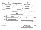
- FIG. 9 is a diagram showing a mounting image in this embodiment.
- driver/hardware has a cpuidle driver (ACPI/intel_idle) 306.
- the kernel includes a task scheduler device 100, a sysfs 303, a cpuidle governor 304, and a cpuidle framework 305.
- the user space includes an epoll_wait 301 and an idle task 302.
- a wait function epoll_wait 301 directly issues a cpuidle_idle_call to the cpuidle framework 305.
- the wait function (epoll_wait 301) itself remains in an executable state, that is, it does not enter a wait state. Moreover, since there is no other process, the task scheduler device 100 has no other process to switch to. As a result, the task scheduler device 100 always allows the wait function (epoll_wait 301) to use time.
- a maximum return time may be specified. Furthermore, the maximum return time may be specified from the standby function (epoll_wait 301) to the kernel sysfs 303 via the sysfs 303 (reference ll in FIG. 9).
- the above-mentioned task scheduler device 100 allows the wait function (epoll_wait301) to always use time while remaining in an executable state. "However, it continues to monopolize the CPU time without yielding it to other processes (threads)."
- the standby process 101 can operate on the same CPU core as the notification process 90 and other processes. On the other hand, in order to maximize the effect, it is desirable that the standby process 101 be on a different CPU core from the notification process 90 and other processes.
- FIG. 10 is a diagram illustrating the scope of application 1 of the task scheduler device 100. The same processes as in FIG. 1 are given the same reference numerals.
- FIG. 11 is a diagram illustrating the application range 2 of the task scheduler device 100.
- the same processes as in FIGS. 1 and 10 are given the same reference numerals.
- the upper left diagram in FIG. 11 is an example where the notification process is User space and the standby process is User space.
- the upper right diagram in FIG. 11 is an example where the notification process is User space and the standby process is Kernel space.
- the lower left diagram in FIG. 11 is an example where the notification process is Kernel space and the standby process is User space.
- the lower right diagram in FIG. 11 is an example where the notification process is Kernel space and the standby process is Kernel space.
- the notification process 90 and the standby process 101 can be placed in either the User space or the Kernel space.
- Examples of file descriptors used for notification include eventfd, singalfd, and timerfd.
- Examples of standby functions that monitor resources include read(), select(), poll(), and epoll(). Both functions perform blocking or non-blocking operations, but when blocking they fall into a state of waiting for the TASK_INTERRUPTIBLE/TASK_UNINTERRUPTIBLE event, so the present invention is applicable thereto.
- FIG. 12 shows a sequence in a case where a pseudo idle function is required before an event occurs.
- the standby process 101 requests the pseudo idle determination unit 130 to start standby (S101).
- the pseudo-idle determining unit 130 requests the return time determining unit 140 to determine the return time (S102).
- the return time determining unit 140 determines the return time (S103). The detailed flow of determining the return time in step S103 will be described later with reference to FIG.
- the return time determining unit 140 notifies the return time setting unit 150 of the return time (S104).
- the return time setting unit 150 sets a return time for the C-state control unit 62 (S1051).
- the C-state control unit 62 responds to the return time setting unit 150 to set the return time (S106).
- the return time setting unit 150 receives the return time setting response from the C-state control unit 62 and sends a return time response to the return time determining unit 140 (S107).
- the return time determining unit 140 notifies the pseudo idle determining unit 130 of the return time determination response from the return time setting unit 150 (S108).
- the pseudo-idle determining unit 130 determines whether the pseudo-idle function is necessary (S109). The detailed flow of determining whether or not the pseudo idle function is necessary in step S109 will be described later with reference to FIG.
- the pseudo-idle determination unit 130 makes a pseudo-idle function request to the standby unit 110 of the standby process 101 (S110).
- the standby unit 110 receives the pseudo-idle function request from the pseudo-idle determining unit 130, and performs stand-by setting and executable state setting (S111).
- the standby unit 110 notifies the pseudo-idle determining unit 130 of a pseudo-idle function response to the pseudo-idle function request (S112).
- the standby unit 110 requests the pseudo idle unit 120 to start pseudo idle (S113).
- the pseudo idle unit 120 requests C-state control from the C-state control unit 62 (S114).
- FIG. 13 shows a sequence in a case where the pseudo idle function before an event occurs is unnecessary. Processes that are the same as the control sequence in FIG. 12 are given the same numbers.
- the standby process 101 requests the pseudo idle determination unit 130 to start standby (S101).
- the pseudo-idle determining unit 130 requests the return time determining unit 140 to determine the return time (S102).
- the return time determining unit 140 determines the return time (S103). The detailed flow of determining the return time in step S103 will be described later with reference to FIG.
- the return time determining unit 140 notifies the return time setting unit 150 of the return time (S104).
- the return time setting unit 150 sets a return time for the C-state control unit 62 (S1051).
- the C-state control unit 62 responds to the return time setting unit 150 to set the return time (S106).
- the return time setting unit 150 receives the return time setting response from the C-state control unit 62 and sends a return time response to the return time determining unit 140 (S107).
- the return time determining unit 140 notifies the pseudo idle determining unit 130 of the return time determination response from the return time setting unit 150 (S108).
- the pseudo-idle determining unit 130 determines whether the pseudo-idle function is necessary (S109). The detailed flow of determining whether or not the pseudo idle function is necessary in step S109 will be described later with reference to FIG.
- the pseudo-idle determining unit 130 makes an idle function request to the standby unit 110 of the standby process 101 (S201).
- the standby unit 110 receives the idle function request from the pseudo-idle determining unit 130 and performs standby setting and standby state setting (S202).
- the standby unit 110 notifies the pseudo-idle determining unit 130 of the idle function response to the idle function request (S203).
- the standby unit 110 requests the scheduler 61 to start idle (S204).
- the scheduler 61 issues an idle start request to the idle unit 51 (S205).
- the idle unit 51 requests C-state control from the C-state control unit 62 (S114).
- FIG. 14 shows a sequence in a case where a pseudo idle function is required after an event occurs.
- the notification process 90 notifies the standby unit 110 using a file descriptor or the like (S301).
- the standby unit 110 requests the pseudo-idle unit 120 to end the pseudo-idle (S302).
- the pseudo idle unit 120 requests C-state control from the C-state control unit 62 (S303).
- the standby unit 110 requests the pseudo-idle determining unit 130 to end the pseudo-idle (S304).
- the pseudo idle determination unit 130 notifies the standby process 101 of the end of the standby process (S305).
- the standby process 101 restarts processing (S306).
- the pseudo idle determination unit 130 sets a return time in the C-state control unit 62 (S307).
- the C-state control unit 62 sends a return time setting response to the pseudo idle determination unit 130 (S308).
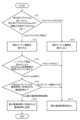
- FIG. 15 is a flowchart for executing the pseudo-idle function in the pseudo-idle determining section 130. This is a detailed flowchart of "determination of necessity of pseudo idle" in step S109 of FIGS. 12 and 13.
- the pseudo-idle determining unit 130 determines whether the number of other processes 104 running on the same core as the standby process 101 while the standby process 101 is in sleep is 0 (see the right diagram in FIG. 10).
- step S12 the pseudo-idle determination unit 130 executes a pseudo-idle function.
- step S13 the pseudo idle determination unit 130 determines whether CPU sleep state control is enabled according to the hardware settings (BIOS).
- step S14 the pseudo idle determination unit 130 determines that the return time determined by the OS governor is longer than the allowable return time. It is determined whether it is larger (return time by OS governor>permissible return time).
- step S11 If the number of other processes 104 running during sleep is not 0 in the above step S11 (S11: No), it is determined that there is no idle task, and in step S16 the pseudo idle determination unit 130 executes the step without executing the pseudo idle function. Proceed to S17.
- step S17 the pseudo idle determination unit 130 ends the process of this flow without specifying the maximum return time.
- FIG. 16 is a flowchart of return time determination in the return time determination unit 140. This is a detailed flowchart of "return time determination" in step S103 of FIGS. 12 and 13. This flow is a method of determining the maximum return time using the actually measured C-state return time.
- the return time determination unit 140 determines (C-state return time allowed by the maximum return time + one step deeper C-state) in step S22. It is determined whether the increment of return time) is smaller than the allowable delay time.
- step S23 the return time determination unit 140 determines time slot #n The process of this flow is ended by setting the maximum return time at +1 + the increment of the return time at a C-state one step deeper (permissible C-state + 1).
- step S21 If the C-state is not the C-state that allows the maximum return time in step S21 (S21: No), it is determined that the return time is shortened, and in step S24 the return time determination unit 140 determines the maximum return time in time slot #n+1.
- the return time difference (acceptable C-state - 1) in the C-state one level shallower is set, and the processing of this flow is ended.
- step S22 if (C-state return time allowed by maximum return time + increment of return time in one step deeper C-state) ⁇ allowable delay time (S22: No), in step S25, the return time determining unit 140: The process of this flow is ended with no correction of the maximum return time.
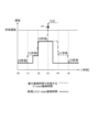
- FIG. 17 is a diagram showing an example of the operation when the maximum return time determination process of FIG. 16 is executed.
- the vertical axis in FIG. 17 shows the allowable delay, and the horizontal axis shows time.
- the broken line in FIG. 17 shows the C-state return time allowed by the maximum return time
- the solid line in FIG. 17 shows the actually measured C-state return time.
- FIG. 17 shows an example in which the target C-state C3 in time slot t3 is not allowed because it exceeds the allowable delay (code oo in FIG. 17).
- the task scheduler device 100 (FIG. 1) according to the above embodiment is realized, for example, by a computer 900 having a configuration as shown in FIG. 18.
- FIG. 18 is a hardware configuration diagram showing an example of a computer 900 that implements the functions of the task scheduler device 100 (FIG. 1).
- the computer 900 has a CPU 901, a ROM 902, a RAM 903, an HDD 904, a communication interface (I/F) 906, an input/output interface (I/F) 905, and a media interface (I/F) 907.
- the CPU 901 operates based on a program stored in the ROM 902 or HDD 904, and controls each part of the task scheduler device 100 (FIG. 1).
- the ROM 902 stores a boot program executed by the CPU 901 when the computer 900 is started, programs depending on the hardware of the computer 900, and the like.
- the CPU 901 controls an input device 910 such as a mouse and a keyboard, and an output device 911 such as a display via an input/output I/F 905.
- the CPU 901 acquires data from the input device 910 via the input/output I/F 905 and outputs the generated data to the output device 911.
- a GPU Graphics Processing Unit
- a GPU Graphics Processing Unit
- the HDD 904 stores programs executed by the CPU 901 and data used by the programs.
- the communication I/F 906 receives data from other devices via a communication network (for example, NW (Network) 922) and outputs it to the CPU 901, and also sends data generated by the CPU 901 to other devices via the communication network. Send to device.
- NW Network
- the media I/F 907 reads the program or data stored in the recording medium 912 and outputs it to the CPU 901 via the RAM 903.
- the CPU 901 loads a program related to target processing from the recording medium 912 onto the RAM 903 via the media I/F 907, and executes the loaded program.
- the recording medium 912 is an optical recording medium such as a DVD (Digital Versatile Disc) or a PD (Phase change rewritable disk), a magneto-optical recording medium such as an MO (Magneto Optical disk), a magnetic recording medium, a conductive memory tape medium, a semiconductor memory, or the like. It is.
- the CPU 901 of the computer 900 executes the task scheduler device by executing a program loaded on the RAM 903. Realizes 100 functions. Furthermore, data in the RAM 903 is stored in the HDD 904 .
- the CPU 901 reads a program related to target processing from the recording medium 912 and executes it. In addition, the CPU 901 may read a program related to target processing from another device via a communication network (NW 922).
- NW 922 a communication network
- the computer system 1000 has a processor consisting of a plurality of cores, and in which a process runs that executes a predetermined instruction using the time on the processor, and the process does not receive notifications.
- a standby process 101 (FIGS. 5 and 7) that remains in a standby state until a notification occurs and resumes operation when a notification is received; and a notification process 90 that sends a notification to wake up the standby process when an event occurs.
- the standby process 101 includes a pseudo idle task 103 (FIGS. 5 and 7) that continues to monopolize the processor when in the standby state.
- the computer system 1000 can cause the standby process 101 to behave in the same way as the idle task 92 (FIGS. 4 and 6) that occurs when there is no process on the processor and does nothing.
- the idle task 92 is not scheduled, and therefore the standby process processing is resumed without a context switch occurring. That is, the pseudo idle task 103 causes the standby process 101 to behave in the same way as the idle task 92, and eliminates context switches from the idle task 92. Therefore, the time required for the standby process to wake up after an event occurs can be reduced.
- the pseudo idle task 103 (FIGS. 5 and 7) is characterized by causing the processor to execute a sleep instruction.
- the pseudo idle task 103 can cause the CPU to execute the sleep (NOP) instruction. That is, the pseudo-idle task 103 maintains a sleep state in which it does not execute anything, and calls and executes the c-state control unit 62 (FIG. 1) that controls the operating state of the CPU instead of the idle unit 51 (FIG. 1). . This makes it possible to reduce CPU cycles and suppress power consumption of the corresponding CPU core.
- NOP sleep
- a task scheduler device 100 that schedules processes in a computer system 1000 (FIG. 1) that has a processor consisting of a plurality of cores and runs a process that executes a predetermined instruction using time on the processor.
- the standby process 101 (FIGS. 5 and 7) remains in a standby state until a notification is received and wakes up and resumes operation when there is a notification.
- a pseudo idle task 103 (FIGS. 5 and 7) that continues to exclusively occupy the processor is provided.
- the task scheduler device 100 restarts the standby process processing without generating a context switch, so it is possible to minimize the time it takes for the standby process to wake up after an event occurs.
- the pseudo idle task 103 (FIGS. 5 and 7) is characterized by causing the processor to execute a sleep instruction.
- the pseudo idle task 103 can cause the CPU to execute the sleep (NOP) instruction. This makes it possible to reduce CPU cycles and suppress power consumption of the corresponding CPU core.
- NOP sleep
- the task scheduler device 100 includes a pseudo-idle determination unit 130 that determines whether to execute a pseudo-idle task 103 based on the process occurrence state on the same processor and/or delay time requirements. It is characterized by
- the pseudo idle task 103 can be executed under appropriate conditions based on the process occurrence state on the processor and the delay time requirements. Since it has the effect of the pseudo-idle task 103 and is executed only under conditions that do not affect other processes, it is possible to achieve the effects of "eliminating context switches due to processor occupancy" and "executing the sleep instruction". .
- a return time setting unit sets a return time until the pseudo idle task 103 (FIGS. 5 and 7) returns after task generation. ).
- the task scheduler device 100 can shorten the delay time until the standby process (standby function) wakes up.
- the return time control unit (return time determination unit 140 and return time setting unit 150) overwrites the determined return time with the maximum return time and shortens the maximum return time. It is characterized by not transitioning to a deep sleep state.
- the task scheduler device 100 can shorten the delay time until the standby process (standby function) wakes up. Therefore, ⁇ Requirement 1: Reduction of notification time> can be satisfied. Furthermore, by increasing the maximum return time, the task scheduler device 100 can transition to a deep sleep state and reduce power consumption in the HW, thereby satisfying ⁇ Requirement 2: Power saving>.
- each of the above-mentioned configurations, functions, processing units, processing means, etc. may be partially or entirely realized by hardware, for example, by designing an integrated circuit.
- each of the above-mentioned configurations, functions, etc. may be realized by software for a processor to interpret and execute a program for realizing each function.
- Information such as programs, tables, files, etc. that realize each function is stored in memory, storage devices such as hard disks, SSDs (Solid State Drives), IC (Integrated Circuit) cards, SD (Secure Digital) cards, optical disks, etc. It can be held on a recording medium.
- Idle process (idle task) 51 Idol part 60 kernel 61 Scheduler 62 C-state control section 90 Notification process 92 Idle task 100 Task scheduler device 101 Standby process 103 Pseudo idle task 110 Standby section 120 Pseudo idle section 130 Pseudo idle judgment section 140 Return time determination section (return time control section) 150 Return time setting section (return time control section) 1000 Computer system CPUcore #m, CPUcore #n,... CPU core
Landscapes
- Engineering & Computer Science (AREA)
- Software Systems (AREA)
- Theoretical Computer Science (AREA)
- Physics & Mathematics (AREA)
- General Engineering & Computer Science (AREA)
- General Physics & Mathematics (AREA)
- Debugging And Monitoring (AREA)
Priority Applications (4)
| Application Number | Priority Date | Filing Date | Title |
|---|---|---|---|
| EP22953190.0A EP4564171A1 (en) | 2022-07-29 | 2022-07-29 | Computer system, task scheduler device, pending process awakening method, and program |
| PCT/JP2022/029347 WO2024024102A1 (ja) | 2022-07-29 | 2022-07-29 | 計算機システム、タスクスケジューラ装置、待ちプロセス起床方法およびプログラム |
| JP2024536743A JPWO2024024102A1 (https=) | 2022-07-29 | 2022-07-29 | |
| CN202280098442.7A CN119604852A (zh) | 2022-07-29 | 2022-07-29 | 计算机系统、任务调度装置、等待进程唤醒方法以及程序 |
Applications Claiming Priority (1)
| Application Number | Priority Date | Filing Date | Title |
|---|---|---|---|
| PCT/JP2022/029347 WO2024024102A1 (ja) | 2022-07-29 | 2022-07-29 | 計算機システム、タスクスケジューラ装置、待ちプロセス起床方法およびプログラム |
Publications (1)
| Publication Number | Publication Date |
|---|---|
| WO2024024102A1 true WO2024024102A1 (ja) | 2024-02-01 |
Family
ID=89705872
Family Applications (1)
| Application Number | Title | Priority Date | Filing Date |
|---|---|---|---|
| PCT/JP2022/029347 Ceased WO2024024102A1 (ja) | 2022-07-29 | 2022-07-29 | 計算機システム、タスクスケジューラ装置、待ちプロセス起床方法およびプログラム |
Country Status (4)
| Country | Link |
|---|---|
| EP (1) | EP4564171A1 (https=) |
| JP (1) | JPWO2024024102A1 (https=) |
| CN (1) | CN119604852A (https=) |
| WO (1) | WO2024024102A1 (https=) |
Citations (2)
| Publication number | Priority date | Publication date | Assignee | Title |
|---|---|---|---|---|
| JPS5955563A (ja) * | 1982-09-22 | 1984-03-30 | Fujitsu Ltd | 情報処理装置 |
| JP2009153192A (ja) * | 2009-03-05 | 2009-07-09 | Canon Inc | 画像形成装置 |
-
2022
- 2022-07-29 EP EP22953190.0A patent/EP4564171A1/en active Pending
- 2022-07-29 JP JP2024536743A patent/JPWO2024024102A1/ja active Pending
- 2022-07-29 WO PCT/JP2022/029347 patent/WO2024024102A1/ja not_active Ceased
- 2022-07-29 CN CN202280098442.7A patent/CN119604852A/zh active Pending
Patent Citations (2)
| Publication number | Priority date | Publication date | Assignee | Title |
|---|---|---|---|---|
| JPS5955563A (ja) * | 1982-09-22 | 1984-03-30 | Fujitsu Ltd | 情報処理装置 |
| JP2009153192A (ja) * | 2009-03-05 | 2009-07-09 | Canon Inc | 画像形成装置 |
Non-Patent Citations (3)
| Title |
|---|
| ANONYMOUS: "See ACPI that supports power management in Windows 10", KADOKAWA ASCII RESEARCH LABORATORIES, 15 September 2019 (2019-09-15), XP093133473, Retrieved from the Internet <URL:https://ascii.jp/elem/000/001/937/1937460/2/> [retrieved on 20240221] * |
| CPU ANALYSIS, 6 July 2022 (2022-07-06), Retrieved from the Internet <URL:https://docs.microsoft.com/ja-jp/windows-hardware/test/wpt/cpu-analysis> |
| CPUIDLE-DO NOTHING, 6 July 2022 (2022-07-06), Retrieved from the Internet <URL:http://landley.net/kdocs/ols/2007/ols2007v2-pages-119-126.pdf> |
Also Published As
| Publication number | Publication date |
|---|---|
| JPWO2024024102A1 (https=) | 2024-02-01 |
| EP4564171A1 (en) | 2025-06-04 |
| CN119604852A (zh) | 2025-03-11 |
Similar Documents
| Publication | Publication Date | Title |
|---|---|---|
| US10649935B2 (en) | Deferred inter-processor interrupts | |
| US8726055B2 (en) | Multi-core power management | |
| CN109906437B (zh) | 基于线程重要性的处理器核停止和频率选择 | |
| US20020007387A1 (en) | Dynamically variable idle time thread scheduling | |
| US20130191844A1 (en) | Management of threads within a computing environment | |
| JP2009093665A (ja) | マルチスレッド・プロセッサ性能を制御する装置及び方法 | |
| US7383450B2 (en) | Low power firmware | |
| EP2972826B1 (en) | Multi-core binary translation task processing | |
| US11061841B2 (en) | System and method for implementing a multi-threaded device driver in a computer system | |
| US7111182B2 (en) | Thread scheduling mechanisms for processor resource power management | |
| US20190163251A1 (en) | Dynamic Interrupt Rate Control in Computing Systems | |
| JP2013222321A (ja) | メモリ制御装置、メモリ制御方法、情報処理装置、およびプログラム | |
| US9274827B2 (en) | Data processing apparatus, transmitting apparatus, transmission control method, scheduling method, and computer product | |
| CN107209737A (zh) | 用于提供对易失性存储器维护事件的内核调度的系统和方法 | |
| KR20120115398A (ko) | 전자 디바이스에서 전력을 제어하는 시스템 및 방법 | |
| US8286169B2 (en) | Dynamic scheduling an interval for polling devices based on a current operational power mode in an extensible firmware interface architecture | |
| US7797473B2 (en) | System for executing system management interrupts and methods thereof | |
| JP2008108075A (ja) | タスク切替え制御方法及びコンピュータシステム | |
| WO2024024102A1 (ja) | 計算機システム、タスクスケジューラ装置、待ちプロセス起床方法およびプログラム | |
| JP5783348B2 (ja) | 制御装置、制御プログラム、画像形成装置 | |
| JP2013522710A (ja) | Itシステムの構成方法、そのコンピュータプログラムおよびitシステム | |
| CN109426563A (zh) | 一种进程管理方法及装置 | |
| JP2006004092A (ja) | コンピュータシステム | |
| WO2023225991A1 (en) | Dynamic establishment of polling periods for virtual machine switching operations | |
| CN119690615A (zh) | 一种任务调度方法以及电子设备 |
Legal Events
| Date | Code | Title | Description |
|---|---|---|---|
| 121 | Ep: the epo has been informed by wipo that ep was designated in this application |
Ref document number: 22953190 Country of ref document: EP Kind code of ref document: A1 |
|
| WWE | Wipo information: entry into national phase |
Ref document number: 202280098442.7 Country of ref document: CN |
|
| WWE | Wipo information: entry into national phase |
Ref document number: 2024536743 Country of ref document: JP |
|
| WWE | Wipo information: entry into national phase |
Ref document number: 2022953190 Country of ref document: EP |
|
| NENP | Non-entry into the national phase |
Ref country code: DE |
|
| ENP | Entry into the national phase |
Ref document number: 2022953190 Country of ref document: EP Effective date: 20250228 |
|
| WWP | Wipo information: published in national office |
Ref document number: 202280098442.7 Country of ref document: CN |
|
| WWP | Wipo information: published in national office |
Ref document number: 2022953190 Country of ref document: EP |