EP4564171A1 - Computer system, task scheduler device, pending process awakening method, and program - Google Patents
Computer system, task scheduler device, pending process awakening method, and program Download PDFInfo
- Publication number
- EP4564171A1 EP4564171A1 EP22953190.0A EP22953190A EP4564171A1 EP 4564171 A1 EP4564171 A1 EP 4564171A1 EP 22953190 A EP22953190 A EP 22953190A EP 4564171 A1 EP4564171 A1 EP 4564171A1
- Authority
- EP
- European Patent Office
- Prior art keywords
- waiting
- task
- idle
- state
- time
- Prior art date
- Legal status (The legal status is an assumption and is not a legal conclusion. Google has not performed a legal analysis and makes no representation as to the accuracy of the status listed.)
- Pending
Links
Images






Classifications
-
- G—PHYSICS
- G06—COMPUTING OR CALCULATING; COUNTING
- G06F—ELECTRIC DIGITAL DATA PROCESSING
- G06F9/00—Arrangements for program control, e.g. control units
- G06F9/06—Arrangements for program control, e.g. control units using stored programs, i.e. using an internal store of processing equipment to receive or retain programs
- G06F9/46—Multiprogramming arrangements
- G06F9/48—Program initiating; Program switching, e.g. by interrupt
- G06F9/4806—Task transfer initiation or dispatching
- G06F9/4843—Task transfer initiation or dispatching by program, e.g. task dispatcher, supervisor, operating system
- G06F9/485—Task life-cycle, e.g. stopping, restarting, resuming execution
-
- G—PHYSICS
- G06—COMPUTING OR CALCULATING; COUNTING
- G06F—ELECTRIC DIGITAL DATA PROCESSING
- G06F9/00—Arrangements for program control, e.g. control units
- G06F9/06—Arrangements for program control, e.g. control units using stored programs, i.e. using an internal store of processing equipment to receive or retain programs
- G06F9/46—Multiprogramming arrangements
- G06F9/48—Program initiating; Program switching, e.g. by interrupt
- G06F9/4806—Task transfer initiation or dispatching
- G06F9/4843—Task transfer initiation or dispatching by program, e.g. task dispatcher, supervisor, operating system
- G06F9/4881—Scheduling strategies for dispatcher, e.g. round robin, multi-level priority queues
-
- G—PHYSICS
- G06—COMPUTING OR CALCULATING; COUNTING
- G06F—ELECTRIC DIGITAL DATA PROCESSING
- G06F9/00—Arrangements for program control, e.g. control units
- G06F9/06—Arrangements for program control, e.g. control units using stored programs, i.e. using an internal store of processing equipment to receive or retain programs
- G06F9/46—Multiprogramming arrangements
- G06F9/48—Program initiating; Program switching, e.g. by interrupt
- G06F9/4806—Task transfer initiation or dispatching
- G06F9/4843—Task transfer initiation or dispatching by program, e.g. task dispatcher, supervisor, operating system
- G06F9/4881—Scheduling strategies for dispatcher, e.g. round robin, multi-level priority queues
- G06F9/4893—Scheduling strategies for dispatcher, e.g. round robin, multi-level priority queues taking into account power or heat criteria
-
- Y—GENERAL TAGGING OF NEW TECHNOLOGICAL DEVELOPMENTS; GENERAL TAGGING OF CROSS-SECTIONAL TECHNOLOGIES SPANNING OVER SEVERAL SECTIONS OF THE IPC; TECHNICAL SUBJECTS COVERED BY FORMER USPC CROSS-REFERENCE ART COLLECTIONS [XRACs] AND DIGESTS
- Y02—TECHNOLOGIES OR APPLICATIONS FOR MITIGATION OR ADAPTATION AGAINST CLIMATE CHANGE
- Y02D—CLIMATE CHANGE MITIGATION TECHNOLOGIES IN INFORMATION AND COMMUNICATION TECHNOLOGIES [ICT], I.E. INFORMATION AND COMMUNICATION TECHNOLOGIES AIMING AT THE REDUCTION OF THEIR OWN ENERGY USE
- Y02D10/00—Energy efficient computing, e.g. low power processors, power management or thermal management
Definitions
- the present invention relates to a computing system, a task scheduler device, a waiting process wake-up method, and a program.
- a general-purpose processor (CPU) is equipped on a computer (hereinafter, a server), and in a case where it is not necessary to always cause a process operating on the CPU to operate, the process is put into a stop state, and a notification is sent from another process at a necessary timing to restore the process to an operating state.
- FIG. 19 is a diagram illustrating inter-process communication in a server by a polling scheme.
- an application (hereinafter, referred to as "APL” as appropriate) [A: Waiting side] 1 requests (S1) APL [B: Notifier side] 1 to perform processing of a task. Thereafter, APL [A: Waiting side] 1 requests (S2) the processing result by polling. APL [B: Notifier side] 1 executes (S3) the task processing requested from APL [A: Waiting side] 1.
- APL [B: Notifier side] 1 transmits (S4) the processing result to APL [A: Waiting side] 1 in response to a polling request.
- APL [A: Waiting side] 1 executes (S5) the next processing.
- FIG. 20 is a diagram illustrating inter-process communication in a server according to a notification scheme. The same processing steps as those in FIG. 19 are denoted by the same step numbers.
- processing of a task is requested (S1) from APL [A: Waiting side] 1 to APL [B: Notifier side] 1.
- APL [A: Waiting side] 1 performs sleep control to enter (S6) a sleep state.
- APL [B: Notifier side] 1 executes (S3) the task processing requested from APL [A: Waiting side] 1.
- APL [B: Notifier side] 1 notifies (S7) APL [A: Waiting side] 1 of processing completion.
- APL [B: Notifier side] 1 upon reception of the result request from APL [A: Waiting side] 1, sends (S4) the processing result to APL [A: Waiting side] 1.
- APL [A: Waiting side] 1 executes (S5) the next processing.
- a certain Process A requests another Process B to perform processing of a task and, until the task processing by Process B is completed, polls whether the task processing has been completed.
- Process A is in an operating state, and thus the power consumption increases.
- the notification scheme of FIG. 20 employs the sleep control in which Process A enters a sleep state after having requested Process B to process the task. As Process A enters a sleep state, the power consumption can be reduced. As Process A enters a sleep state, Process B notifies Process A of completion of the processing, and Process A having received the notification wakes up from sleep and requests the processing-completed task from Process B. However, as Process A wakes up from sleep, a latency time for restoration occurs.
- FIG. 21 is a diagram illustrating a notification system using eventfd + epoll_wait.
- a server includes hardware (HW) 10, an OS 20, and in a user space, a waiting process [core #n] 30 and a notification process [core #m] 32 .
- waiting process [core #n] 30 is "Process A" of APL [A: Waiting side] 1
- notification process [core #m] 32 is "Process B" of APL [B: Notifier side] 1.
- Hardware (HW) 10 includes a CPU 11. Waiting process [core #n] 30 has a waiting function 31.
- OS 20 includes an event monitoring instance 21 and a notification file descriptor (FD) 22.
- Notification FD 22 is an integer value that designates a file when requesting an access from OS 20. This is assigned when a file is operated from a program to discriminate • (hereinafter, "•" represents "and") identify the file to be operated.
- notification and wake-up are performed in a flow of 1. to 9. in FIG. 21 .
- notification process 32 may be executed by notification process 32.
- FIG. 22 is a diagram illustrating a waiting process of the existing technique described in Non-Patent Literature 1.
- a waiting process 40 includes a waiting part 41 and a sleep part 42, and an idle process 50 (idle task) includes an idle part 51.
- a kernel 60 of the OS includes a scheduler 61 and a C-state control part 62 (C-state will be described later).
- Idle process 50 disappears when another process (thread) exists on the CPU core.
- waiting part 41 calls sleep part 42 to cause the process (waiting process 40) to enter a wait state.
- scheduler 61 calls a process having idle part 51.
- Idle part 51 causes the CPU to transition to a sleep state or turns off the power by using C-state control part 62.
- context switching refers to a process of saving/(hereinafter, "/" represents “or")restoring a state (context) of a CPU so that a plurality of processes can share one CPU.
- the C-state restoration time is determined by the kernel.
- the kernel determines the depth of the C-state based on an idle time estimated by C-state control part 62.
- a restoration time from the corresponding C-state occurs (Non-Patent Literature 2).
- FIG. 23 is a diagram illustrating an example of C-states in the form of a table. Note that as the state definition varies depending on the CPU hardware, FIG. 23 is merely a reference example.
- CPUidle state has grades C0 to C6, and transitions to a deep sleep state occur as the time during which the CPU has no load becomes long. Although the power consumption of the CPU becomes less in the deeper sleep state, the time required until restoration is extended accordingly, which may possibly raise an issue in the perspective of low latency.
- the depth to which the CPUidle state transitions is controlled by the CPU hardware, which is dependent on the CPU product (often cannot be controlled by software such as a kernel).
- the existing technique has a problem of an increase in the latency time.
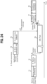
- FIG. 24 is a diagram illustrating a problem of the existing technique.
- the lower part of FIG. 24 is the schedule of a waiting process (core #n); and the upper part of FIG. 24 is the schedule of a notification process (core #m).
- the waiting process processing 71 enters a sleep state at 4., there is a possibility that an idle task will be scheduled for the pertinent CPU core.
- the event receiver (core #n) shifts to the idle task 76 by a context switch (reference sign a in FIG. 24 ).
- a context switch reference sign a in FIG. 24 .
- an idle task 76 appears if in an idle state where no other process is loaded on the pertinent CPU core.
- the idle task 76 operates, the CPU core (event receiver (core #n)) falls stepwise into a deep sleep state (CPU idle), and thus the power consumption can be reduced.
- the idle task 76 When the waiting function wakes up at 8, the idle task 76 is scheduled again, and then the waiting function is scheduled via a context switch (reference sign c in FIG. 24 ) to proceed to 9. waiting process processing resumption (number 78 in FIG. 24 ).
- the context switch generally switches between a state of operating in a kernel space and a state of operating in a user space.
- a large latency occurs due to the context switch (reference sign c in FIG. 24 ) from the idle task 76 to the waiting function wake-up 77 ( ⁇ symbol d in FIG. 24 ). That is, a context switch time at the time of switching to the waiting function occurs, so that a large latency occurs.
- the CPU causes stepwise or directly the sleep state to transition until the sleep state (C-state) allowed by the governor of the OS is reached.
- the governor of the OS allows a deep sleep state as a policy of the entire server (for example, C6), a long restoration time of 100 ⁇ s or more occurs until reverting to the operating state (C0) of the CPU.
- FIG. 25 is a diagram in which a C-state transition image of the CPU core used for operations is superimposed on the schedule in FIG. 24 .
- the CPU core is in a deep sleep state (CPUidle state: Grade C6), in which case the latency time until restoration after the occurrence (reference sign e in FIG. 25 ) of a task is extended.
- a deep CPU idle state When the state falls into a deep CPU idle state, it takes a long time for the restoration, and there is a problem in that the real-time capability is impaired.
- the above problem is a problem that is not allowed to be overlooked in a system in which real-time capability is prioritized like a base station (BBU).
- BBU base station
- BBUs base stations
- a measure for invalidating the C-state or setting for limiting the transition of the idle state to a limited depth such as C1 is employed. That is, there are cases in which real-time capability oriented tuning is performed at the expense of power saving property.
- the present invention has been made in view of such a background, and an object of the present invention is to reduce the time taken until a waiting process wakes up after the occurrence of an event.
- a computing system which comprises a processor composed of a plurality of cores and in which a process that executes a predetermined command using a time on the processor operates, wherein the process includes: a waiting process that transitions into and remains in a wait state until notified and wakes up to resume an operation when notified; and a notification process that transmits a notification to wake up the waiting process when an event occurs, and wherein the waiting process has a pseudo idle task that, when being in a waiting state, continues to occupy the processor.
- FIG. 1 is a schematic configuration diagram of a computing system according to the embodiment of the present invention.
- the same components as those in FIG. 22 are denoted by the same reference signs.
- the present embodiment is an example applied to a CPU as a computing system.
- the present invention can be similarly applied to a processor such as a graphic processing unit (GPU), a field programmable gate array (FPGA), and an application specific integrated circuit (ASIC) when the processor is equipped with an idle state function.
- a processor such as a graphic processing unit (GPU), a field programmable gate array (FPGA), and an application specific integrated circuit (ASIC) when the processor is equipped with an idle state function.
- GPU graphic processing unit
- FPGA field programmable gate array
- ASIC application specific integrated circuit
- a computing system 1000 includes a kernel 60, CPU cores (core #m, core #n, and core #x) 80, a notification process 90, an idle process 50, and a task scheduler device 100.
- Kernel 60 includes a scheduler 61, a C-state control part 62, a file descriptor (fd) 63 such as eventfd, and a socket (communication socket) 64 such as Unix Domain Socket.
- fd file descriptor
- socket communication socket
- Idle process 50 includes an idle part 51. Idle process 50 allows, while waiting, another process (thread) to use the pertinent CPU core.
- Computing system 1000 is a computing system which includes a processor composed of a plurality of cores and in which a process executing predetermined commands using a time on the processor operates, the process including: a waiting process 101 that transitions into and remains in a wait state until notified and wakes up and resumes an operation when notified, a notification process 90 that, upon occurrence of an event, transmits a notification to wake up the waiting process, and an idle process 50 that occurs when there is no process on the processor and executes nothing.
- Task scheduler device 100 includes a waiting part 110, a pseudo idle part 120, a pseudo idle determination part 130, a restoration time determination part 140 (restoration time control part), and a restoration time setting part 150 (restoration time control part).
- Waiting part 110 and pseudo idle part 120 constitute a waiting process 101 to cooperate with idle part 51 of idle process 50 (idle task).
- Pseudo idle determination part 130, restoration time determination part 140, and restoration time setting part 150 constitute a management part 102.
- Waiting process 101 transitions into and remains in a wait state until notified, and wakes up and resumes an operation when notified.
- Waiting part 110 remains in an executable state. Waiting part 110, upon reception of a pseudo idle function request from pseudo idle determination part 130, configures a wait setting and an executable state setting. Specifically, waiting part 110, according to an instruction from pseudo idle determination part 130, executes pseudo idle part 120 or performs context switching to an idle process having an idle function.
- Pseudo idle part 120 remains in a sleep (NOP) state in which pseudo idle part 120 executes nothing.
- Pseudo idle part 120 as a substitute of idle part 51, calls and executes C-state control part 62 that controls the operating state of the CPU.
- Pseudo idle part 120 has a pseudo idle task 103 ( FIGS. 5 and 7 ) such that, when being in a waiting state, waiting process 101 continues to occupy the processor.
- the scheduler of the Kernel gives an execution time to waiting process 101 when an event occurs.
- pseudo idle task 103 having been executed immediately before is being executed as extension of the waiting process, it is possible to eliminate context switching associated with process switching.
- Pseudo idle determination part 130 determines whether to execute pseudo idle part 120 (pseudo idle task) based on a process occurrence state on the same processor and/or a requirement of the latency time, to be instructed to waiting part 110.
- the reason why it is necessary to determine whether to execute pseudo idle part 120 is that, as will be described later with reference to FIG. 10 , in a situation where the notification process and the waiting process are operating on the same CPU core, there is no effect of operating the pseudo idle part to eliminate context switching and there is a possibility of affecting other processes, such as an increase in the processing delay.
- Restoration time determination part 140 determines a restoration time corresponding to a C-state to which pseudo idle part 120 can fall at the maximum based on the requirement of the latency time and the current C-state. Restoration time determination part 140 notifies restoration time setting part 150 of the maximum restoration time.
- Restoration time setting part 150 sets the maximum restoration time to C-state control part 62 using the maximum restoration time from restoration time determination part 140. Restoration time setting part 150 reverts the maximum restoration time to its original again after pseudo idle part 120 finishes.
- Restoration time determination part 140 and restoration time setting part 150 constitute a restoration time setting part that sets a restoration time until pseudo idle task 103 is restored after the occurrence of a task.
- This restoration time control part is a functional part that overwrites a determined restoration time with the maximum restoration time and configures the maximum restoration time short, so that a transition to a deep sleep state is not caused.
- the waiting process is caused to behave the same as an idle task, to eliminate the context switching from the idle task.
- FIG. 2 is a diagram illustrating context switch elimination (Feature ⁇ 1>). The same processes as those in FIG. 24 are denoted by the same reference signs.
- the lower part of FIG. 2 is the schedule of an event receiver (core #n), and the upper part of FIG. 2 is the schedule of an event sender (core #m).
- notification FD writing 74 causes execution of 7. event monitor callback 75, where the event sender (core #m) performs an inter-processor interrupt (reference sign b in FIG. 2 ) on the event receiver (core #n).
- waiting function behaves equivalently to the idle task, scheduling of the idle task is not executed in 8. waiting function wake-up. Thus 9. waiting process processing resumption 78 follows without an occurrence of context switching (reference sign cc in FIG. 2 ).
- the CPU core can fall into a deep sleep state while the waiting function operates, similarly to the idle task (number 76 in FIG. 24 ). With this, ⁇ Requirement 2: Power Saving Property> can be satisfied.
- a maximum restoration time of the pseudo idle task is designated to control not to cause a fall to a deep sleep state.
- the restoration time determined by the governor of the OS is overwritten with the maximum restoration time, and the maximum restoration time is configured short. Accordingly, the computing system does not transition to a deep sleep state, so it is possible to shorten the latency time until the waiting function wakes up. With this, ⁇ Requirement 1: Reduction of Notification Time> is satisfied.
- FIG. 3 is a diagram in which an image of C-state transition of a CPU core used for operation is superimposed on the schedule of FIG. 2 .
- the same processes as those in FIG. 25 are denoted by the same reference signs.
- a restoration time maximum value (reference sign ee in FIG. 3 ) from the occurrence of a task (reference sign dd in FIG. 3 ) to the restoration is designated.
- the reason why such designation of the restoration time maximum value is possible is that the waiting function • waiting function wake-up 201 in which the waiting function behaves equivalently to the idle task is provided and that the schedule of the waiting function • waiting function wake-up 201 can have a degree of freedom.
- the maximum restoration time maximum value when the maximum restoration time is set short, as the CPU core falls into a shallow sleep state, the power reduction is small. When the maximum restoration time is set long, as the CPU core falls into a deep sleep state, the power reduction is large. However, when the CPU core falls into a deep sleep state, it takes time to restore.
- FIG. 4 is a diagram illustrating the behavior of a waiting process in the cases of ⁇ when waiting starts>, ⁇ while waiting>, and ⁇ when event occurs> in the comparative example.
- the same configurations • processes as those in FIG. 1 are denoted by the same reference signs.
- the server includes a CPU core 80 (event receiver (core #n)) and a CPU core 80 (event sender (core #m)).
- a waiting process 91 is in a task queue 85 on CPU core 80 (core #n).
- wait state means that, on CPU core 80 (core #n), waiting process 91 enters a waiting queue 86.
- waiting process 91 exits (arrow f in FIG. 4 ) from task queue 85 and enters waiting queue 86 on the right side of FIG. 4 to be in a wait state.
- an idle task 92 appears on CPU core 80 (core #n).
- This idle task 92 is a process (task) that automatically appears so that task queue 85 does not become empty.
- waiting process 91 At the time when the kernel mode detects an event issuance, upon reception of a notification from a notification process 90 via an fd 63 and a socket 64 of kernel 60 ( FIG. 1 ), waiting process 91 returns (arrow g in FIG. 4 ) to task queue 85 in the center of FIG. 4 again.
- waiting process 91 returns to task queue 85, a context switch between idle task 92 and waiting process 91 occurs (reference sign c in FIG. 24 ).
- FIG. 5 is a diagram illustrating the behavior of the waiting process in the cases of ⁇ when waiting starts>, ⁇ while waiting>, and ⁇ when event occurs> in the present embodiment.
- the same configurations • processes as those in FIGS. 1 and 4 are denoted by the same reference signs.
- a server includes a CPU core 80 (event receiver (core #n)) and a CPU core 80 (event sender (core #m)).
- a waiting process 101 is in a task queue 85 on CPU core 80 (core #n). At the time ⁇ when waiting starts>, the behavior of the waiting process is the same between the present embodiment and the comparative example.
- waiting process 101 includes waiting part 110 and pseudo idle part 120 ( FIG. 1 ). That is, waiting process 101 further introduces pseudo idle part 120 (pseudo idle task 103) into waiting process 91 of FIG. 4 .
- pseudo idle task 103 continues to occupy CPU core 80 (core #n) so as not to cause waiting process 101 to enter the task queue 85. That is, with the introduction of pseudo idle task 103, the corresponding CPU core is continuously occupied without yielding the corresponding CPU core to other processes. More specifically, the occupation of the CPU core means continuously occupying the CPU core without yielding CPU time.
- pseudo idle task 103 issues an epoll, but continues to occupy the CPU time without yielding CPU time to other processes (threads).
- waiting process 101 continues to remain in task queue 85. That is, in the comparative example of FIG. 4 , while waiting, waiting process 91 exits from task queue 85 and enters waiting queue 86 to be in the wait state.
- pseudo idle task 103 issues an epoll
- pseudo idle task 103 continues to occupy the CPU time without yielding CPU time to other processes (threads), so that waiting process 101 continues to remain in the task queue.
- pseudo idle task 103 continues to occupy CPU core 80 (core #n)
- waiting process 101 is able to continue to remain in task queue 85, and thus no context switch occurs.
- CPU core 80 (core #n) is able to shift to an idle state.
- Pseudo idle task 103 of the present embodiment operates in a manner analogous to idle task 92.
- Pseudo idle task 103 is a task that does basically nothing similarly to idle task 92.
- pseudo idle task 103 is able to cause the CPU to execute a sleep (NOP) command. With this, it is possible to reduce the CPU cycle and reduce the power consumption of the CPU core.
- NOP sleep
- waiting process 101 receives a notification from notification process 90 via an fd 63 and a socket 64 of kernel 60 ( FIG. 1 ). As waiting process 101 continues to remain (reference sign gg in FIG. 5 ) in task queue 85, at the time when waiting process 101 receives the notification when the kernel mode detects an event issuance, waiting process 101 is already in task queue 85. Thus, no context switch occurs (reference sign cc in FIG. 2 ).
- FIG. 6 is a diagram illustrating the behavior of the waiting process in the cases of ⁇ when waiting starts>, ⁇ while waiting>, and ⁇ when event occurs> in the comparative example.
- the same configurations • processes as those in FIG. 4 are denoted by the same reference signs.
- task scheduler device 100 allocates a CPU execution time to a process in an executable state (TASK_RUNNING) in task queue 85.
- task scheduler device 100 gives (reference sign h in FIG. 6 ) an execution time to the waiting process.
- task scheduler device 100 gives an execution time to idle task 92.
- a context switch occurs (reference sign i in FIG. 6 ).
- waiting process 91 exits (arrow j in FIG. 6 ) from task queue 85 and enters waiting queue 86 to be in a wait state.
- task scheduler device 100 When waiting process 91 is called at the time of the occurrence of an event, task scheduler device 100 gives an execution time to waiting process 91. At this time, a context switch occurs (reference sign k in FIG. 6 ). In addition, waiting process 91 returns (arrow l in FIG. 4 ) to task queue 85 in the center of FIG. 6 again.
- FIG. 7 is a diagram illustrating the behavior of the waiting process in the cases of ⁇ when waiting starts>, ⁇ while waiting>, and ⁇ when event occurs> in the present embodiment.
- the same configurations • processes as those in FIG. 5 are denoted by the same reference signs.
- task scheduler device 100 allocates a CPU execution time to a process in an executable state (TASK_RUNNING) in task queue 85.
- task scheduler device 100 gives (reference sign hh in FIG. 7 ) an execution time to waiting process 101.
- task scheduler device 100 gives (reference sign ii in FIG. 7 ) an execution time to waiting process 101. That is, as pseudo idle task 103 continues to occupy CPU core 80 (core #n) (see ⁇ while waiting> in FIG. 5 ), waiting process 101 is able to continue to remain in task queue 85, and thus no context switch occurs.
- task scheduler device 100 gives (reference sign jj in FIG. 7 ) an execution time to waiting process 101.
- FIG. 8 is a diagram illustrating an implementation image in the comparative example.
- the driver/hardware includes a cpuidle driver (ACPI/intel_idle) 306.
- the kernel includes a task scheduler device 100, a sysfs 303, a cpuidle governor 304, and a cpuidle framework 305.
- the user space has an epoll_wait 301 and an idle task 302.
- task scheduler device 100 switches the process using the kernel function switch_to.
- a context switch (reference sign c in FIG. 8 ) for switching from epoll_wait 301 to idle task 302 is executed.
- FIG. 9 is a diagram illustrating an implementation image of the present embodiment.
- the driver/hardware includes cpuidle driver (ACPI/intel_idle) 306.
- the kernel includes task scheduler device 100, sysfs 303, cpuidle governor 304, and cpuidle framework 305.
- the user space has an epoll _wait 301 and an idle task 302.
- a waiting function (epoll_wait 301) directly issues cpuidle_idle_call to cpuidle framework 305.
- the waiting function (epoll_wait 301) itself remains in the executable state, that is, does not enter a wait state.
- task scheduler device 100 has no other process as a destination of switching. Accordingly, task scheduler device 100 causes the waiting function (epoll_wait 301) to use time always.
- a maximum restoration time may be designated.
- the waiting function may designate (reference sign ll in FIG. 9 ) the maximum restoration time to sysfs 303 of the kernel via sysfs 303.
- the configuration where task scheduler device 100 causes the waiting function (epoll_wait 301) to use time always in the executable state corresponds to the configuration where "pseudo idle task 103 issues an epoll, but continues to occupy the CPU time without yielding the CPU time to other processes (threads)", described regarding ⁇ While waiting> in FIG. 5 .
- Waiting process 101 can also operate even on the same CPU core as notification process 90 and other processes. On the other hand, in order to maximize the effect, it is desirable that waiting process 101 be on a CPU core different from notification process 90 and other processes.
- FIG. 10 is a diagram illustrating an application scope 1 of task scheduler device 100. The same processes as those in FIG. 1 are denoted by the same reference signs.
- notification process 90 and waiting process 101 operate on different CPU cores (core #m and core #n).
- Notification process 90 and waiting process 101 coexist on the same CPU core (core #n). Notification process 90 and waiting process 101 compete for CPU time (reference sign mm in the middle diagram in FIG. 10 ).
- notification process 90 and waiting process 101 anywhere in the user space/kernel space.
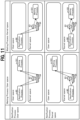
- FIG. 11 is a diagram illustrating an application scope 2 of task scheduler device 100.
- the same processes as those in FIGS. 1 and 10 are denoted by the same reference signs.
- the upper left diagram in FIG. 11 is an example of a case where the notification process is in the user space and the waiting process is in the user space.
- the upper right diagram in FIG. 11 is an example of a case where the notification process is in the user space and the waiting process is in the kernel space.
- the lower left diagram in FIG. 11 is an example of a case where the notification process is in the kernel space and the waiting process is in the user space.
- the lower right diagram of FIG. 11 is an example of a case where the notification process is in the kernel space and the waiting process is in the kernel space.
- notification process 90 and waiting process 101 can be arranged in either the user space or the Kernel space.
- Examples of the file descriptor to be used for the notification include eventfd, singalfd, timerfd, and the like.
- Examples of the waiting function for monitoring a resource include read(), select(), poll(), and epoll(). Any of the functions performs a blocking or non-blocking operation, but at the time of blocking, the function falls into a state of event waiting of TASK_INTERRUPTIBLE/TASK_UNINTERRUPTIBLE, and thus the present invention can be applied.
- FIG. 12 illustrates a sequence in a case where the pseudo idle function prior to occurrence of event is necessary.
- Waiting process 101 requests (S101) pseudo idle determination part 130 to start waiting.
- Pseudo idle determination part 130 requests (S102) restoration time determination part 140 to determine a restoration time.
- Restoration time determination part 140 determines (S103) the restoration time. A detailed flow of the restoration time determination in step S 103 will be described later with reference to FIG. 16 .
- Restoration time determination part 140 notifies (S104) restoration time setting part 150 of the restoration time.
- Restoration time setting part 150 applies (S1051) a restoration time setting to C-state control part 62.
- C-state control part 62 responds (S106) to restoration time setting part 150 with a response to the restoration time setting.
- restoration time setting part 150 Upon reception of the restoration time setting response from C-state control part 62, restoration time setting part 150 responds (S107) to restoration time determination part 140 with a response regarding the restoration time.
- Restoration time determination part 140 notifies (S108) pseudo idle determination part 130 of a restoration time determination response from restoration time setting part 150.
- Pseudo idle determination part 130 makes (S109) a pseudo idle function necessity determination. A detailed flow of the pseudo idle function necessity determination in step S109 will be described later with reference to FIG. 15 .
- Pseudo idle determination part 130 makes (S110) a pseudo idle function request to waiting part 110 of waiting process 101.
- waiting part 110 Upon reception of the pseudo idle function request from pseudo idle determination part 130, waiting part 110 configures (S111) a wait setting and an executable state setting.
- Waiting part 110 notifies (S112) pseudo idle determination part 130 of a pseudo idle function response to the pseudo idle function request.
- Waiting part 110 requests (S113) pseudo idle part 120 to start pseudo idling.
- Pseudo idle part 120 requests (S114) C-state control part 62 to perform C-state control.
- FIG. 13 illustrates a sequence in a case where the pseudo idle function prior to occurrence of event is unnecessary.
- the same processes as those in the control sequence of FIG. 12 are denoted by the same reference numerals.
- Waiting process 101 requests (S101) pseudo idle determination part 130 to start waiting.
- Pseudo idle determination part 130 requests (S102) restoration time determination part 140 to determine a restoration time.
- Restoration time determination part 140 determines (S103) the restoration time. A detailed flow of the restoration time determination in step S103 will be described later with reference to FIG. 15 .
- Restoration time determination part 140 notifies (S104) restoration time setting part 150 of the restoration time .
- Restoration time setting part 150 applies (S1051) a restoration time setting to C-state control part 62.
- C-state control part 62 responds (S106) to restoration time setting part 150 with a response to the restoration time setting.
- restoration time setting part 150 Upon reception of the restoration time setting response from C-state control part 62, restoration time setting part 150 responds (S107) to restoration time determination part 140 with a response regarding the restoration time.
- Restoration time determination part 140 notifies pseudo idle determination part 130 of a restoration time determination response from restoration time setting part 150 (S108).
- Pseudo idle determination part 130 makes (S109) a pseudo idle function necessity determination. A detailed flow of the pseudo idle function necessity determination in step S109 will be described later with reference to FIG. 16 .
- Pseudo idle determination part 130 makes (S201) an idle function request to waiting part 110 of waiting process 101.
- waiting part 110 Upon reception of the idle function request from pseudo idle determination part 130, waiting part 110 configures (S202) a wait setting and a wait state setting.
- Waiting part 110 notifies (S203) pseudo idle determination part 130 of an idle function response to the idle function request.
- Waiting part 110 requests (S204) scheduler 61 to start idling.
- Scheduler 61 makes (S205) an idle start request to idle part 51.
- Idle part 51 requests (S114) C-state control part 62 to perform C-state control.
- FIG. 14 is a sequence in a case where the pseudo idle function after the occurrence of an event is necessary.
- Notification process 90 makes (S301) a notification with a file descriptor or the like to waiting part 110.
- Waiting part 110 requests (S302) pseudo idle part 120 to finish the pseudo idling.
- Pseudo idle part 120 requests (S303) C-state control part 62 to perform C-state control.
- Waiting part 110 requests (S304) pseudo idle determination part 130 to finish the pseudo idling.
- Pseudo idle determination part 130 notifies (S305) waiting process 101 of the finish of waiting.
- Pseudo idle determination part 130 applies (S307) a restoration time setting to C-state control part 62.
- C-state control part 62 responds (S308) to pseudo idle determination part 130 with a restoration time setting response.
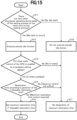
- FIG. 15 is a flowchart of executing the pseudo idle function in pseudo idle determination part 130. This is a detailed flow of the "pseudo idle necessity determination" in step S109 of FIGS. 12 and 13 .
- pseudo idle determination part 130 determines whether there are zero other processes 104 operating during sleep of waiting process 101 on the same core as waiting process 101 (see the right diagram in FIG. 10 ).
- pseudo idle determination part 130 determines that an idle task will occur and executes the pseudo idle function in step S12.
- pseudo idle determination part 130 determines that C-state is available, and in step S14, determines whether the restoration time according to the governor of the OS is longer than an allowable restoration time (restoration time according to the governor of the OS > allowable restoration time).
- pseudo idle determination part 130 determines that no idle task is present and in step S16, does not execute the pseudo idle function and proceeds to step S17.
- step S17 pseudo idle determination part 130 finishes the processing of this flow without designating the maximum restoration time.
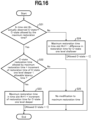
- FIG. 16 is a flowchart of determining the restoration time by restoration time determination part 140. This is a detailed flow of the "restoration time determination" in step S103 of FIGS. 12 and 13 .
- This flow is a method of determining the maximum restoration time using a C-state restoration time actually measured.
- step S22 restoration time determination part 140 determines whether (the C-state restoration time allowed by the maximum restoration time + increment of the restoration time for the C-state one level deeper) is shorter than the allowable latency time.
- restoration time determination part 140 sets the maximum restoration time in the time slot #n+1 + the increment of the restoration time for the C-state one level deeper (allowed C-state + 1), and finishes the processing of this flow.
- restoration time determination part 140 determines that the restoration time should be shortened and in step S24, sets the maximum restoration time in the time slot #n+1 - the difference in the restoration time of the C-state one level shallower (allowable C-state - 1), and finishes the processing of this flow.
- step S25 restoration time determination part 140 determines not to modify the maximum restoration time and finishes the processing of this flow.
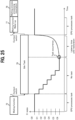
- FIG. 17 is a diagram illustrating an operation example in a case where the maximum restoration time determination processing of FIG. 16 is executed.
- the vertical axis represents allowable latency
- the horizontal axis represents time.
- the dashed line in FIG. 17 indicates the C-state restoration time allowed by the maximum restoration time
- the solid line in FIG. 17 indicates the C-state restoration time actually measured.
- FIG. 17 illustrates an example in which the target C-state being C3 was not allowed (reference sign oo in FIG. 17 ) in time slot t3, as the allowable latency was exceeded.
- Task scheduler device 100 ( FIG. 1 ) according to the above embodiment is implemented by a computer 900 having a configuration as illustrated in FIG. 18 , for example.
- FIG. 18 is a hardware configuration diagram illustrating an example of a computer 900 that implements the functions of task scheduler device 100 ( FIG. 1 ).
- Computer 900 includes a CPU 901, a ROM 902, a RAM 903, an HDD 904, a communication interface (I/F) 906, an input/output interface (I/F) 905, and a media interface (I/F) 907.
- a CPU 901 a ROM 902, a RAM 903, an HDD 904, a communication interface (I/F) 906, an input/output interface (I/F) 905, and a media interface (I/F) 907.
- CPU 901 operates based on a program stored in ROM 902 or HDD 904, and controls each part of task scheduler device 100 ( FIG. 1 ).
- ROM 902 stores a boot program to be executed by CPU 901 when computer 900 is started up, a program that relies on the hardware of computer 900, and the like.
- CPU 901 controls an input device 910, such as a mouse and a keyboard, and an output device 911, such as a display, via input/output I/F 905.
- CPU 901 acquires data from the input device 910 and outputs generated data to the output device 911 via input/output I/F 905.
- a graphics processing unit GPU or the like may be used as a processor in conjunction with CPU 901.
- HDD 904 stores a program to be executed by CPU 901, data to be used by the program, and the like. Further, communication I/F 906 receives data from another device via a communication network (for example, network (NW) 922), outputs the data to CPU 901, and transmits data generated by CPU 901 to another device via the communication network.
- a communication network for example, network (NW) 922
- Media I/F 907 reads a program or data stored in a recording medium 912, and outputs the program or data to CPU 901 via RAM 903.
- CPU 901 loads a program related to target processing from recording medium 912 onto RAM 903 via media I/F 907, and executes the loaded program.
- Recording medium 912 is an optical recording medium such as a digital versatile disc (DVD) or a phase change rewritable disk (PD), a magneto-optical recording medium such as a magneto optical disk (MO), a magnetic recording medium, a conductor memory tape medium, a semiconductor memory, or the like.
- CPU 901 of computer 900 implements the function of task scheduler device 100 by executing a program loaded on RAM 903. Further, HDD 904 stores data in RAM 903. CPU 901 reads a program related to target processing from recording medium 912, and executes the program. Additionally, CPU 901 may read the program related to the target processing from other devices via the communication network (NW 922).
- NW 922 the communication network
- computing system 1000 is able to cause waiting process 101 to behave the same as idle task 92 ( FIGS. 4 and 6 ) that occurs when there is no process on the processor and executes nothing.
- scheduling of idle task 92 is not executed and thus the waiting process processing resumes without an occurrence of context switching.
- pseudo idle task 103 causes waiting process 101 to behave the same as idle task 92 to eliminate context switching from idle task 92. Therefore, it is possible to reduce the time taken until the waiting process wakes up after the occurrence of an event.
- pseudo idle task 103 causes the processor to execute a sleep command.
- pseudo idle task 103 is able to cause the CPU to execute a sleep (NOP) command. That is, pseudo idle task 103 remains in a sleep state in which pseudo idle task 103 executes nothing and, as a substitute of idle part 51 ( FIG. 1 ), calls and executes C-state control part 62 ( FIG. 1 ) that controls the operating state of the CPU. With this, it is possible to reduce the CPU cycle and reduce the power consumption of the CPU core.
- NOP sleep
- a task scheduler device 100 ( FIG. 1 ) that, in a computing system 1000 ( FIG. 1 ) which includes a processor composed of a plurality of cores and in which a process that executes a predetermined command using a time on the processor operates, schedules the process, task scheduler device 100 including: a waiting process 101 ( FIG. 5 , FIG. 7 ) that transitions into and remains in a wait state until notified and wakes up and resumes an operation when notified; and a pseudo idle task 103 ( FIG. 5 , FIG. 7 ) such that, when being in a waiting state, waiting process 101 occupies the processor.
- task scheduler device 100 is able to minimize the time taken until the waiting process wakes up after the occurrence of an event.
- pseudo idle task 103 causes the processor to execute a sleep command.
- pseudo idle task 103 can cause the CPU to execute a sleep (NOP) command. With this, it is possible to reduce the CPU cycle and reduce the power consumption of the CPU core.
- NOP sleep
- Task scheduler device 100 ( FIG. 1 ) further includes a pseudo idle determination part 130 that determines whether to execute pseudo idle task 103 based on a process occurrence state on a same processor and/or a requirement of a latency time.
- pseudo idle task 103 is able to be executed under appropriate conditions based on the process occurrence state on the processor and/or the requirement of the latency time. As pseudo idle task 103 provides effects and is executed only under a condition that does not affect other processes, it is possible to achieve the effect of "context switch elimination due to processor occupation" and the effect of "causing a sleep command to be executed”.
- Task scheduler device 100 ( FIG. 1 ) further includes a restoration time setting part (restoration time determination part 140 and restoration time setting part 150) that sets a restoration time until pseudo idle task 103 ( FIGS. 5 and 7 ) is restored after a task occurs.
- a restoration time setting part (restoration time determination part 140 and restoration time setting part 150) that sets a restoration time until pseudo idle task 103 ( FIGS. 5 and 7 ) is restored after a task occurs.
- task scheduler device 100 is able to shorten the latency time until the waiting process (waiting function) wakes up.
- a restoration time control part (restoration time determination part 140 and restoration time setting part 150) overwrites a determined restoration time with a maximum restoration time and configures the maximum restoration time short, so that a transition to a deep sleep state is not caused.
- task scheduler device 100 is able to shorten the latency time until the waiting process (waiting function) wakes up.
- ⁇ Requirement 1 Reduction of Notification Time> can be satisfied.
- task scheduler device 100 is able to cause a transition to a deep sleep state to reduce the power in the HW by taking the maximum restoration time long, leading to fulfillment of ⁇ Requirement 2: Power Saving Property>.
- each of the components of each of the devices illustrated in the drawings is functionally conceptual, and is not required to be physically designed as illustrated.
- a specific form of distribution • integration of individual devices is not limited to the illustrated form, and all or part of the configuration can be functionally or physically distributed • integrated in any unit according to various loads, usage conditions, and the like.
Landscapes
- Engineering & Computer Science (AREA)
- Software Systems (AREA)
- Theoretical Computer Science (AREA)
- Physics & Mathematics (AREA)
- General Engineering & Computer Science (AREA)
- General Physics & Mathematics (AREA)
- Debugging And Monitoring (AREA)
Applications Claiming Priority (1)
| Application Number | Priority Date | Filing Date | Title |
|---|---|---|---|
| PCT/JP2022/029347 WO2024024102A1 (ja) | 2022-07-29 | 2022-07-29 | 計算機システム、タスクスケジューラ装置、待ちプロセス起床方法およびプログラム |
Publications (1)
| Publication Number | Publication Date |
|---|---|
| EP4564171A1 true EP4564171A1 (en) | 2025-06-04 |
Family
ID=89705872
Family Applications (1)
| Application Number | Title | Priority Date | Filing Date |
|---|---|---|---|
| EP22953190.0A Pending EP4564171A1 (en) | 2022-07-29 | 2022-07-29 | Computer system, task scheduler device, pending process awakening method, and program |
Country Status (4)
| Country | Link |
|---|---|
| EP (1) | EP4564171A1 (https=) |
| JP (1) | JPWO2024024102A1 (https=) |
| CN (1) | CN119604852A (https=) |
| WO (1) | WO2024024102A1 (https=) |
Family Cites Families (2)
| Publication number | Priority date | Publication date | Assignee | Title |
|---|---|---|---|---|
| JPS5955563A (ja) * | 1982-09-22 | 1984-03-30 | Fujitsu Ltd | 情報処理装置 |
| JP4440326B2 (ja) * | 2009-03-05 | 2010-03-24 | キヤノン株式会社 | 画像形成装置 |
-
2022
- 2022-07-29 EP EP22953190.0A patent/EP4564171A1/en active Pending
- 2022-07-29 JP JP2024536743A patent/JPWO2024024102A1/ja active Pending
- 2022-07-29 WO PCT/JP2022/029347 patent/WO2024024102A1/ja not_active Ceased
- 2022-07-29 CN CN202280098442.7A patent/CN119604852A/zh active Pending
Also Published As
| Publication number | Publication date |
|---|---|
| JPWO2024024102A1 (https=) | 2024-02-01 |
| WO2024024102A1 (ja) | 2024-02-01 |
| CN119604852A (zh) | 2025-03-11 |
Similar Documents
| Publication | Publication Date | Title |
|---|---|---|
| AU2014311461B2 (en) | CPU scheduler configured to support latency sensitive virtual machines | |
| US7831980B2 (en) | Scheduling threads in a multi-processor computer | |
| EP2885707B1 (en) | Latency sensitive software interrupt and thread scheduling | |
| US7487503B2 (en) | Scheduling threads in a multiprocessor computer | |
| JP5317010B2 (ja) | 仮想マシン配置システム、仮想マシン配置方法、プログラム、仮想マシン管理装置およびサーバ装置 | |
| US8261284B2 (en) | Fast context switching using virtual cpus | |
| JPH0969017A (ja) | コンピュータ・システムの電力管理方法及び装置 | |
| US7111182B2 (en) | Thread scheduling mechanisms for processor resource power management | |
| De Alfonso et al. | An energy management system for cluster infrastructures | |
| EP4557052A1 (en) | Task scheduler device, calculation system, and task scheduling method, and program | |
| EP4564171A1 (en) | Computer system, task scheduler device, pending process awakening method, and program | |
| Wada et al. | Fast interrupt handling scheme by using interrupt wake-up mechanism | |
| US7765548B2 (en) | System, method and medium for using and/or providing operating system information to acquire a hybrid user/operating system lock | |
| JP2008225641A (ja) | コンピュータシステム、割り込み制御方法及びプログラム | |
| Lee et al. | Delayed locking technique for improving real-time performance of embedded linux by prediction of timer interrupt | |
| JP2006004092A (ja) | コンピュータシステム | |
| Yang et al. | Real-Time Vehicle Operating System Analysis, Construction and Testing | |
| JP2025134149A (ja) | 情報処理システム、プログラム及び情報処理方法 | |
| CN121478427A (zh) | 一种任务调度方法及装置 | |
| Labrosse | Embedded Operating Systems | |
| Hong et al. | New Scheme of Implementing Real-Time Linux | |
| HK1104102B (en) | Method and system for concurrent execution of mutiple kernels |
Legal Events
| Date | Code | Title | Description |
|---|---|---|---|
| STAA | Information on the status of an ep patent application or granted ep patent |
Free format text: STATUS: THE INTERNATIONAL PUBLICATION HAS BEEN MADE |
|
| PUAI | Public reference made under article 153(3) epc to a published international application that has entered the european phase |
Free format text: ORIGINAL CODE: 0009012 |
|
| STAA | Information on the status of an ep patent application or granted ep patent |
Free format text: STATUS: REQUEST FOR EXAMINATION WAS MADE |
|
| 17P | Request for examination filed |
Effective date: 20250224 |
|
| AK | Designated contracting states |
Kind code of ref document: A1 Designated state(s): AL AT BE BG CH CY CZ DE DK EE ES FI FR GB GR HR HU IE IS IT LI LT LU LV MC MK MT NL NO PL PT RO RS SE SI SK SM TR |
|
| RAP3 | Party data changed (applicant data changed or rights of an application transferred) |
Owner name: NTT, INC. |
|
| DAV | Request for validation of the european patent (deleted) | ||
| DAX | Request for extension of the european patent (deleted) | ||
| REG | Reference to a national code |
Ref country code: DE Ref legal event code: R079 Free format text: PREVIOUS MAIN CLASS: G06F0009540000 Ipc: G06F0009480000 |