WO2024024102A1 - Computer system, task scheduler device, pending process awakening method, and program - Google Patents
Computer system, task scheduler device, pending process awakening method, and program Download PDFInfo
- Publication number
- WO2024024102A1 WO2024024102A1 PCT/JP2022/029347 JP2022029347W WO2024024102A1 WO 2024024102 A1 WO2024024102 A1 WO 2024024102A1 JP 2022029347 W JP2022029347 W JP 2022029347W WO 2024024102 A1 WO2024024102 A1 WO 2024024102A1
- Authority
- WO
- WIPO (PCT)
- Prior art keywords
- standby
- idle
- task
- pseudo
- state
- Prior art date
Links
- 238000000034 method Methods 0.000 title claims abstract description 310
- 230000008569 process Effects 0.000 title claims abstract description 290
- 230000007958 sleep Effects 0.000 claims description 60
- 230000002618 waking effect Effects 0.000 claims 2
- 230000006870 function Effects 0.000 description 74
- 238000010586 diagram Methods 0.000 description 51
- 238000012545 processing Methods 0.000 description 28
- 238000005516 engineering process Methods 0.000 description 17
- 230000000052 comparative effect Effects 0.000 description 16
- 230000007704 transition Effects 0.000 description 16
- 238000012544 monitoring process Methods 0.000 description 13
- 230000004044 response Effects 0.000 description 11
- 238000004891 communication Methods 0.000 description 10
- 230000000694 effects Effects 0.000 description 10
- 230000006399 behavior Effects 0.000 description 9
- 238000004364 calculation method Methods 0.000 description 6
- 238000011084 recovery Methods 0.000 description 6
- 230000009467 reduction Effects 0.000 description 6
- 230000000903 blocking effect Effects 0.000 description 4
- 230000003287 optical effect Effects 0.000 description 3
- 238000012546 transfer Methods 0.000 description 3
- 238000004458 analytical method Methods 0.000 description 2
- 230000006872 improvement Effects 0.000 description 2
- 238000003491 array Methods 0.000 description 1
- 230000008859 change Effects 0.000 description 1
- 238000012937 correction Methods 0.000 description 1
- 230000001934 delay Effects 0.000 description 1
- 230000008030 elimination Effects 0.000 description 1
- 238000003379 elimination reaction Methods 0.000 description 1
- 230000007717 exclusion Effects 0.000 description 1
- 230000007246 mechanism Effects 0.000 description 1
- 230000002035 prolonged effect Effects 0.000 description 1
- 239000004065 semiconductor Substances 0.000 description 1
- 239000007787 solid Substances 0.000 description 1
- 238000012360 testing method Methods 0.000 description 1
Images


Classifications
-
- G—PHYSICS
- G06—COMPUTING; CALCULATING OR COUNTING
- G06F—ELECTRIC DIGITAL DATA PROCESSING
- G06F9/00—Arrangements for program control, e.g. control units
- G06F9/06—Arrangements for program control, e.g. control units using stored programs, i.e. using an internal store of processing equipment to receive or retain programs
- G06F9/46—Multiprogramming arrangements
- G06F9/54—Interprogram communication
-
- Y—GENERAL TAGGING OF NEW TECHNOLOGICAL DEVELOPMENTS; GENERAL TAGGING OF CROSS-SECTIONAL TECHNOLOGIES SPANNING OVER SEVERAL SECTIONS OF THE IPC; TECHNICAL SUBJECTS COVERED BY FORMER USPC CROSS-REFERENCE ART COLLECTIONS [XRACs] AND DIGESTS
- Y02—TECHNOLOGIES OR APPLICATIONS FOR MITIGATION OR ADAPTATION AGAINST CLIMATE CHANGE
- Y02D—CLIMATE CHANGE MITIGATION TECHNOLOGIES IN INFORMATION AND COMMUNICATION TECHNOLOGIES [ICT], I.E. INFORMATION AND COMMUNICATION TECHNOLOGIES AIMING AT THE REDUCTION OF THEIR OWN ENERGY USE
- Y02D10/00—Energy efficient computing, e.g. low power processors, power management or thermal management
Definitions
- the present invention relates to a computer system, a task scheduler device, a waiting process wake-up method, and a program.
- a computer (hereinafter referred to as a server) is equipped with a general-purpose processor (CPU), and if a process running on the CPU does not need to be constantly running, the process is stopped and separated when necessary. A process may be returned to a running state by sending a notification from that process.
- CPU general-purpose processor
- FIG. 19 is a diagram showing inter-process communication within the server using the polling method.
- an application hereinafter referred to as "APL" [A: waiting side] 1 requests APL [B: notifying side] 1 to process a task (S1).
- APL [A: waiting side] 1 requests the processing result by polling (S2).
- APL [B: notification side] 1 executes the task processing requested by APL [A: waiting side] 1 (S3).
- APL [B: notification side] 1 sends the processing result to APL [A: waiting side] 1 in response to the polling request (S4).
- APL [A: Waiting side] 1 executes the following process (S5).
- FIG. 20 is a diagram showing inter-process communication within the server using the notification method. The same steps as those in FIG. 19 are given the same step numbers. As shown in FIG. 20, APL [A: waiting side] 1 requests APL [B: notifying side] 1 to process a task (S1). APL [A: waiting side] 1 performs sleep control and enters a sleep state (S6).
- APL [B: notification side] 1 executes the task processing requested by APL [A: waiting side] 1 (S3).
- APL [B: notification side] 1 notifies APL [A: waiting side] 1 of the completion of the process (S7).
- APL [A: Waiting side] 1 receives the processing completion notification from APL [B: Notifying side] 1 (S7), wakes up from the sleep state, and requests the processing result from APL [B: Notifying side] 1. (S8).
- APL [B: notification side] 1 receives the result request from APL [A: wait side] 1, and sends the processing result to APL [A: wait side] 1 (S4).
- APL [A: Waiting side] 1 executes the following process (S5).
- a process A requests another process B to process a task, and polls until the task process in process B is completed to see if it has been completed.
- Process A is in operation and power consumption increases.
- sleep control is adopted in which process A enters a sleep state after requesting process B to process a task. Since process A enters the sleep state, power consumption can be reduced.
- process B notifies process A of the completion of processing, and process A that receives the notification wakes up from sleep and requests process B to complete the task. However, since process A wakes up from sleep, a delay time occurs for recovery.
- FIG. 21 is a diagram showing a notification system using eventfd+epoll_wait.
- the server includes hardware (HW) 10, an OS 20, a standby process [core #n] 30, and a notification process [core #m] 32 in the user space.
- the standby process [core #n] 30 is "process A" of APL [A: waiting side] 1
- the notification process [core #m] 32 is "process A" of APL [B: notifying side] 1.
- Process B is a diagram showing a notification system using eventfd+epoll_wait.
- the hardware (HW) 10 includes a CPU 11.
- the standby process [core #n] 30 has a standby function 31 .
- the OS 20 includes an event monitoring instance 21 and a notification FD (File Descriptor) 22.
- the notification FD 22 is an integer value that specifies a file when requesting access to the OS 20. When operating a file from a program, it is assigned to identify the file to be operated (hereinafter, ".” represents "and").
- a standby process 30 (“process A”) creates an event monitoring instance 21 (eventpoll). 2.
- the standby process 30 creates a notification FD 22 (eventfd), which is an FD used for notifications, and performs the above 1. to the event monitoring instance 21 of. 3.
- the standby process 30 transfers the notification FD 22 to the notification process 32 ("process B").
- process A creates an event monitoring instance 21
- process B creates a notification FD 22
- process B the notification process 32
- the standby process 30 performs the above 1. It specifies the event monitoring instance 21, issues the wait function 31 (epoll_wait), and enters a blocking (sleep) state. When the standby function 31 (epoll_wait) is issued, the standby process 30 enters a sleep state until an event is issued. The standby process 30 itself goes into a sleep state, but if there is no other process on the corresponding CPU core, which corresponds to an idle state, when the standby process 30 goes into a sleep state, An idle task will appear. This idle task is a state in which the CPU core does nothing, but automatically appears when there are no processes.
- the notification process 32 detects the occurrence of an event and writes it to the notification FD 22. 7. When writing is performed to the notification FD 22, an event monitoring callback is executed (occurs). 8. When an event monitoring callback occurs, an instruction is sent to the standby function 31 that is waiting for the event monitoring instance 21. The designated standby function 31 detects the event and wakes up. 9. The standby process 30 that called the standby function 31 resumes processing. In addition, above 2. In some cases, the notification FD creation is executed on the notification process 32 side.
- FIG. 22 is a diagram illustrating the standby process of the existing technology described in Non-Patent Document 1.
- the standby process 40 has a standby section 41 and a sleep section 42
- the idle process 50 (idle task) has an idle section 51.
- the OS kernel 60 includes a scheduler 61 and a C-state control unit 62 (C-state will be described later).
- the idle process 50 disappears when another process (thread) exists on the CPU core.
- the standby unit 41 calls the sleep unit 42, and the process (standby process 40) enters the standby state.
- the scheduler 61 calls the process having the idle part 51 if there is no other process in an executable state.
- the idle unit 51 uses the C-state control unit 62 to transition the CPU to a sleep state or turn off the power.
- Context switching refers to the process of saving/restoring the state (context) of a CPU (hereinafter, "/" represents "or") so that multiple processes can share one CPU.
- the C-state return time is determined by the kernel.
- the kernel determines the depth of the C-state based on the idle time estimated by the C-state control unit 62. There is a time required to return from the corresponding C-state (Non-Patent Document 2).
- FIG. 23 is a diagram showing an example of C-state states in a table. Note that since the state definition differs depending on the CPU hardware, FIG. 23 is just a reference example. As shown in FIG. 23, the CPUidle state has grades C0 to C6, and as the time when the CPU is not loaded increases, the state transitions to a deep sleep state. A deep sleep state consumes less CPU power, but on the other hand, it lengthens the time it takes to return, which may pose a problem in terms of low latency.
- C-state differs depending on the CPU hardware. For example, there are variations such as a model without C4 or C5, and a model in which the state following C1 is C1E. As the state becomes deeper, the power saving effect increases, but the time required to return from the idle state also increases.
- the depth to which the CPUidle state transitions is controlled by the CPU hardware and depends on the CPU product (in many cases, it cannot be controlled from software such as the kernel).
- FIG. 24 is a diagram illustrating problems with existing technology.
- the lower part of FIG. 24 shows the schedule of the standby process (core #n), and the upper part of FIG. 24 shows the schedule of the notification process (core #m).
- an idle task may be scheduled for the corresponding CPU core.
- the event receiver (core #n) transitions to the idle task 76 by a context switch (reference numeral a in FIG. 24) after executing the standby process processing 71 and the standby function 72.
- the idle task 76 appears if the corresponding CPU core is in the idle state with no other processes running on it.
- the CPU core (event receiver (core #n)) falls into a deep sleep state (CPU idle) in stages, making it possible to reduce power consumption.
- event sender (core #m) is 5. When an event occurs, 6. By writing to the notification FD 74, 7. The event monitoring callback 75 is executed, and the event sender (core #m) issues an inter-processor interrupt (reference numeral b in FIG. 24) to the event receiver (core #n).
- step 9 When the standby function wakes up in step 9, the idle task 76 is scheduled again, and then the standby function is scheduled via a context switch (reference numeral c in FIG. 24).9. The standby process processing is resumed (number 78 in FIG. 24).
- a context switch generally switches between operating in Kernel space and operating in User space. This context switch from the idle task 76 to the standby function wake-up 77 (sign c in FIG. 24) causes a large delay (marked with ⁇ d in FIG. 24). That is, a context switch time occurs when switching to the standby function, resulting in a large delay.
- FIG. 25 is a diagram showing a C-state transition image of a CPU core used for calculations superimposed on the schedule of FIG. 24.
- the CPU core is in a deep sleep state (CPUidle state: grade C6), and the delay time until recovery after a task is generated (code e in Figure 25) is prolonged. do.
- the CPU drops to a deep idle state, it takes a long time to recover, which impairs real-time performance.
- the base station (BBU) takes measures such as disabling the C-state or introducing settings that limit the transition of the idle state to a limited depth such as C1. In other words, tuning may be performed in favor of real-time performance at the expense of power saving.
- the present invention was made in view of this background, and an object of the present invention is to reduce the time required for a standby process to wake up after an event occurs.
- a computer system has a processor consisting of multiple cores and runs a process that executes a predetermined instruction using the time on the processor, and the process runs until notified.
- a standby process that enters a standby state and wakes up and resumes operation when there is a notification, and a notification process that sends a notification to wake up the standby process when an event occurs, and the standby process is set to a standby state.
- the computer system is characterized in that it has a pseudo-idle task that continues to occupy the processor when the computer is running.
- FIG. 1 is a schematic configuration diagram of a computer system according to an embodiment of the present invention.
- FIG. 2 is a diagram illustrating context switch elimination (feature ⁇ 1>) of the computer system according to the embodiment of the present invention.
- FIG. 2 is a diagram showing a C-state transition image of a CPU core superimposed on a schedule of a CPU core used for calculations in a computer system according to an embodiment of the present invention.
- FIG. 6 is a diagram showing the behavior of the standby process at ⁇ at the start of standby>, ⁇ during standby>, and ⁇ at the time of event occurrence> in a comparative example of the computer system according to the embodiment of the present invention.
- FIG. 1 is a schematic configuration diagram of a computer system according to an embodiment of the present invention.
- FIG. 2 is a diagram illustrating context switch elimination (feature ⁇ 1>) of the computer system according to the embodiment of the present invention.
- FIG. 2 is a diagram showing a C-state transition image of a CPU core
- FIG. 3 is a diagram illustrating the behavior of the standby process of the computer system according to the embodiment of the present invention ⁇ at the start of standby>, ⁇ during standby>, and ⁇ at the time of occurrence of an event>.
- FIG. 6 is a diagram showing the behavior of the standby process at ⁇ at the start of standby>, ⁇ during standby>, and ⁇ at the time of event occurrence> in a comparative example of the computer system according to the embodiment of the present invention.
- FIG. 3 is a diagram illustrating the behavior of the standby process of the computer system according to the embodiment of the present invention ⁇ at the start of standby>, ⁇ during standby>, and ⁇ at the time of occurrence of an event>.
- FIG. 2 is a diagram showing an implementation image in a comparative example of a computer system according to an embodiment of the present invention.
- 1 is a diagram showing an implementation image of a computer system according to an embodiment of the present invention.
- FIG. 1 is a diagram illustrating an application range 1 of a computer system according to an embodiment of the present invention.
- FIG. 2 is a diagram illustrating a second scope of application of the computer system according to the embodiment of the present invention. This is a sequence in a case where a pseudo idle function is required before an event occurs in a computer system according to an embodiment of the present invention.
- This is a sequence in a case where the pseudo idle function before an event occurs in the computer system according to the embodiment of the present invention is unnecessary.
- FIG. 7 is a flowchart for executing a pseudo-idle function in a pseudo-idle determination unit of a computer system according to an embodiment of the present invention. It is a flowchart of the maximum return time determination in the return time determination part of the computer system based on embodiment of this invention.
- FIG. 3 is a diagram illustrating an example of the operation when the maximum recovery time determination process of the computer system according to the embodiment of the present invention is executed.
- FIG. 1 is a hardware configuration diagram showing an example of a computer that implements the functions of a task scheduler device of a computer system according to an embodiment of the present invention.
- FIG. 2 is a diagram illustrating inter-process communication within a server using a polling method.
- FIG. 2 is a diagram illustrating inter-process communication within a server using a notification method. It is a diagram showing a notification system using eventfd+epoll_wait.
- FIG. 2 is a diagram illustrating a standby process of existing technology.
- FIG. 3 is a diagram illustrating an example of C-state states in a table form.
- FIG. 2 is a diagram illustrating problems with existing technology.
- 25 is a diagram showing a C-state transition image of a CPU core used for calculations superimposed on the schedule of FIG. 24.
- FIG. 1 is a schematic configuration diagram of a computer system according to an embodiment of the present invention. Components that are the same as those in FIG. 22 are given the same reference numerals.
- This embodiment is an example in which the present invention is applied to a CPU as a computer system.
- the present invention is also applicable to processors such as GPUs (Graphic Processing Units), FPGAs (Field Programmable Gate Arrays), and ASICs (Application Specific Integrated Circuits), if they have an idle state function.
- GPUs Graphic Processing Units
- FPGAs Field Programmable Gate Arrays
- ASICs Application Specific Integrated Circuits
- the computer system 1000 includes a kernel 60, CPU cores (core #m, core #n, core #x) 80, a notification process 90, an idle process 50, and a task scheduler device 100.
- the kernel 60 includes a scheduler 61, a C-state control unit 62, an fd (file descriptor) 63 such as eventfd, and a socket (communication socket) 64 such as Unix Domain Socket.
- the idle process 50 has an idle section 51.
- the idle process 50 allows other processes (threads) to use the corresponding CPU core while it is on standby.
- the computer system 1000 has a processor consisting of a plurality of cores, and a process that executes a predetermined instruction using the time on the processor runs, and the process is in a waiting state until a notification is received.
- a standby process 101 that wakes up and resumes operation when an event occurs
- a notification process 90 that sends a notification to wake up the standby process when an event occurs
- an idle process 50 that occurs when there is no process on the processor and does not execute anything.
- the task scheduler device 100 includes a standby section 110, a pseudo-idle section 120, a pseudo-idle judgment section 130, a return time determination section 140 (return time control section), and a return time setting section 150 (return time control section). , is provided.
- the standby unit 110 and the pseudo-idle unit 120 constitute the standby process 101, and cooperate with the idle unit 51 of the idle process 50 (idle task).
- the pseudo idle determining section 130, the return time determining section 140, and the return time setting section 150 constitute the management section 102.
- the standby process 101 remains in a standby state until a notification is received, and when there is a notification, it wakes up and resumes operation.
- the standby unit 110 maintains an executable state.
- the standby unit 110 receives a pseudo-idle function request from the pseudo-idle determining unit 130, and performs a stand-by setting and an executable state setting. Specifically, in response to an instruction from the pseudo-idle determination unit 130, the pseudo-idle unit 120 is executed or a context switch is performed to an idle process having an idle function.
- the pseudo idle unit 120 maintains a sleep (NOP) state in which it does not execute anything.
- the pseudo idle unit 120 calls and executes the C-state control unit 62 that controls the operating state of the CPU instead of the idle unit 51.
- the pseudo-idle unit 120 has a pseudo-idle task 103 (FIGS. 5 and 7) in which the stand-by process 101 continues to monopolize the processor when in the stand-by state.
- the Kernel scheduler gives execution time to the standby process 101 when an event occurs. Since the pseudo idle task 103 that is being executed immediately before is executed as an extension of the standby process, a context switch accompanying process switching can be eliminated.
- the pseudo-idle determining unit 130 determines whether to execute the pseudo-idle unit 120 (pseudo-idle task) based on the process occurrence state on the same processor and/or the delay time requirements, and sends the pseudo-idle task to the standby unit 110. Instruct.
- the reason why it is necessary to determine whether to execute the pseudo-idle section 120 is that, as will be described later in FIG. This is because it is not effective in eliminating context switches by running , and it may also have an impact on other processes, such as increasing processing delays.
- the return time determining unit 140 determines the return time corresponding to the C-state in which the pseudo idle unit 120 can fall at maximum, based on the delay time requirements and the current C-state.
- the return time determining section 140 notifies the return time setting section 150 of the maximum return time.
- the return time setting unit 150 sets the maximum return time in the C-state control unit 62 using the maximum return time from the return time determining unit 140.
- the return time setting unit 150 returns to the original maximum return time again after the pseudo idle unit 120 ends.
- the return time determining section 140 and the return time setting section 150 described above constitute a return time setting section that sets the return time until the pseudo idle task 103 returns after task generation.
- This return time control unit is a functional unit that overwrites the determined return time with the maximum return time and shortens the maximum return time to prevent transition to a deep sleep state.
- FIG. 2 is a diagram illustrating context switch exclusion (feature ⁇ 1>). The same processes as in FIG. 24 are given the same reference numerals. The lower part of FIG. 2 shows the schedule of the event receiver (core #n), and the upper part of FIG. 2 shows the schedule of the event sender (core #m). Below 1. ⁇ 3. Assume that has been executed at initialization. 1. Event monitoring instance creation 2. Create notification FD/register event monitoring instance 3. Notification FD transfer
- the event receiver executes the process without transitioning to the idle task (without generating a context switch) (symbol aa in FIG. 2); 4. Standby function ⁇ 8.
- the standby function wakes up 201. That is, in the standby function/standby function wake-up 201, 4.
- the standby function behaves in the same way as an idle task (symbol bb in FIG. 2).
- event sender (core #m) is 5. When an event occurs, 6. By writing to the notification FD 74, 7. The event monitoring callback 75 is executed, and the event sender (core #m) issues an inter-processor interrupt (reference numeral b in FIG. 2) to the event receiver (core #n).
- the standby function behaves the same as an idle task. 9. When the standby function wakes up, the idle task is not scheduled, so a context switch (symbol cc in FIG. 2) does not occur. The standby process process resumes 78.
- Feature ⁇ 2> Specify the return time of the pseudo idle task Specify the maximum return time of the pseudo idle task and control it so that it does not fall into a deep sleep state.
- the return time determined by the OS governor is overwritten with the maximum return time to shorten the maximum return time.
- ⁇ Requirement 1 Reduction of notification time>.
- ⁇ Requirement 2 Power saving>.
- FIG. 3 is a diagram showing a C-state transition image of a CPU core used for calculations superimposed on the schedule of FIG. 2.
- the same processes as in FIG. 25 are given the same reference numerals.
- the maximum return time (sign ee in FIG. 3) from task generation (code dd in FIG. 3) to recovery is specified.
- the reason why such a maximum return time can be specified is that a standby function/standby function wake-up 201 is provided so that the stand-by function behaves in the same way as an idle task, and the schedule of this stand-by function/standby function wake-up 201 is flexible.
- FIG. 4 is a diagram showing the behavior of the standby process at ⁇ at the start of standby>, ⁇ during standby>, and ⁇ at the time of event occurrence> in the comparative example.
- the same configurations and processes as in FIG. 1 are given the same reference numerals.
- the server includes a CPU core 80 (event receiver (core #n)) and a CPU core 80 (event sender (core #m)).
- the standby process 91 is in the task queue 85 on the CPU core 80 (core #n).
- the so-called waiting state means that the waiting process 91 enters the waiting queue 86 on the CPU core 80 (core #n).
- the standby process 91 leaves the task queue 85 (arrow f in FIG. 4), enters the wait queue 86 on the right side of FIG. 4, and enters the wait state.
- the idle task 92 is on the CPU core 80 (core #n). Appear.
- This idle task 92 is a process (task) that automatically appears so that the task queue 85 does not become empty.
- the standby process 91 receives a notification from the notification process 90 via fd63 and socket64 of the kernel 60 (FIG. 1), and returns to the task queue 85 in the center of FIG. 4 (arrow in FIG. 4). g). When the standby process 91 returns to the task queue 85, a context switch between the idle task 92 and the standby process 91 occurs (reference numeral c in FIG. 24).
- FIG. 5 is a diagram showing the behavior of the standby process at ⁇ at the start of standby>, ⁇ during standby>, and ⁇ at the time of occurrence of an event> in this embodiment.
- Components and processes that are the same as those in FIGS. 1 and 4 are designated by the same reference numerals.
- the server includes a CPU core 80 (event receiver (core #n)) and a CPU core 80 (event sender (core #m)).
- the standby process 101 is in the task queue 85 on the CPU core 80 (core #n).
- the behavior of the standby process is the same in this embodiment and the comparative example.
- the standby process 101 includes a standby section 110 and a pseudo idle section 120 (FIG. 1). That is, the standby process 101 further introduces a pseudo idle section 120 (pseudo idle task 103) into the standby process 91 of FIG. Since the pseudo idle task 103 does not generate an idle task 92, it continues to exclusively occupy the CPU core 80 (core #n) so as to prevent the standby process 101 from entering the task queue 85. That is, by introducing the pseudo-idle task 103, the CPU core continues to be exclusively occupied without surrendering the CPU core to another process. More specifically, monopolizing the CPU core means continuing to monopolize the CPU time without giving up. Specifically, the pseudo idle task 103 issues an epoll, but continues to monopolize the CPU time without yielding it to other processes (threads).
- the standby process 101 continues to remain in the task queue 85. That is, in the comparative example shown in FIG. 4, during standby, the standby process 91 exits the task queue 85 and enters the wait queue 86 to be in a standby state. In contrast, in the present embodiment, although the pseudo idle task 103 issues an epoll, it continues to monopolize the CPU time without giving up the CPU time to other processes (threads), so that the standby process 101 continues to remain in the task queue.
- the pseudo idle task 103 continues to exclusively occupy the CPU core 80 (core #n), so the standby process 101 can continue to remain in the task queue 85, and no context switch occurs.
- the presence of the idle task 92 in the task queue 85 enabled the CPU core 80 (core #n) to transition to the idle state.
- the pseudo idle task 103 of this embodiment operates in the same way as the idle task 92.
- the pseudo idle task 103 is a task that basically does nothing like the idle task 92, but since there is a pseudo idle task 103 that operates in the same way as the idle task 92, the pseudo idle task 103 can cause the CPU to sleep. (NOP) instruction can be executed. This makes it possible to reduce the CPU cycle and suppress the power consumption of the corresponding CPU core.
- the standby process 101 receives a notification from the notification process 90 via the fd 63 and socket 64 of the kernel 60 (FIG. 1). Since the standby process 101 continues to remain in the task queue 85 (symbol gg in FIG. 5), it is already in the task queue 85 when it receives a notification when event issuance is detected in the kernel mode. Therefore, no context switch occurs (symbol cc in FIG. 2).
- FIG. 6 is a diagram showing the behavior of the standby process at ⁇ at the start of standby>, ⁇ during standby>, and ⁇ at the time of event occurrence> in the comparative example. Components and processes that are the same as those in FIG. 4 are given the same reference numerals. It is assumed that the task scheduler device 100 allocates CPU execution time to processes in the task queue 85 that are in an executable state (TASK_RUNNING).
- the task scheduler device 100 gives execution time to the standby process (reference numeral h in FIG. 6).
- the task scheduler device 100 generates an idle task 92 when the task queue 85 becomes empty, and gives execution time to the idle task 92. At this time, a context switch occurs (symbol i in FIG. 6). Also, during standby, the standby process 91 leaves the task queue 85 (arrow j in FIG. 6), enters the wait queue 86, and enters the wait state.
- the task scheduler device 100 gives execution time to the standby process 91. At this time, a context switch occurs (symbol k in FIG. 6). Further, the standby process 91 returns to the task queue 85 in the center of FIG. 6 again (arrow l in FIG. 4).
- FIG. 7 is a diagram showing the behavior of the standby process at ⁇ at the start of standby>, ⁇ during standby>, and ⁇ at the time of occurrence of an event> in this embodiment. Components and processes that are the same as those in FIG. 5 are given the same reference numerals. It is assumed that the task scheduler device 100 allocates CPU execution time to processes in the task queue 85 that are in an executable state (TASK_RUNNING).
- the task scheduler device 100 gives execution time to the standby process 101 (reference hh in FIG. 7).
- the task scheduler device 100 gives execution time to the standby process 101 (reference numeral ii in FIG. 7). That is, since the pseudo idle task 103 continues to exclusively occupy the CPU core 80 (core #n) (see ⁇ Standby> in FIG. 5), the standby process 101 can continue to remain in the task queue 85, and the context switch is not performed. Does not occur.
- the task scheduler device 100 gives execution time to the standby process 101 (symbol jj in FIG. 7).
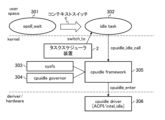
- FIG. 8 is a diagram showing an implementation image in a comparative example.
- driver/hardware has a cpuidle driver (ACPI/intel_idle) 306.
- the kernel includes a task scheduler device 100, a sysfs 303, a cpuidle governor 304, and a cpuidle framework 305.
- the user space has an epoll_wait 301 and an idle task 302.
- the task scheduler device 100 switches the process using the kernel function switch_to.
- a context switch (represented by c in FIG. 8) from epoll_wait 301 to idle task 302 is executed.
- FIG. 9 is a diagram showing a mounting image in this embodiment.
- driver/hardware has a cpuidle driver (ACPI/intel_idle) 306.
- the kernel includes a task scheduler device 100, a sysfs 303, a cpuidle governor 304, and a cpuidle framework 305.
- the user space includes an epoll_wait 301 and an idle task 302.
- a wait function epoll_wait 301 directly issues a cpuidle_idle_call to the cpuidle framework 305.
- the wait function (epoll_wait 301) itself remains in an executable state, that is, it does not enter a wait state. Moreover, since there is no other process, the task scheduler device 100 has no other process to switch to. As a result, the task scheduler device 100 always allows the wait function (epoll_wait 301) to use time.
- a maximum return time may be specified. Furthermore, the maximum return time may be specified from the standby function (epoll_wait 301) to the kernel sysfs 303 via the sysfs 303 (reference ll in FIG. 9).
- the above-mentioned task scheduler device 100 allows the wait function (epoll_wait301) to always use time while remaining in an executable state. "However, it continues to monopolize the CPU time without yielding it to other processes (threads)."
- the standby process 101 can operate on the same CPU core as the notification process 90 and other processes. On the other hand, in order to maximize the effect, it is desirable that the standby process 101 be on a different CPU core from the notification process 90 and other processes.
- FIG. 10 is a diagram illustrating the scope of application 1 of the task scheduler device 100. The same processes as in FIG. 1 are given the same reference numerals.
- FIG. 11 is a diagram illustrating the application range 2 of the task scheduler device 100.
- the same processes as in FIGS. 1 and 10 are given the same reference numerals.
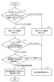
- the upper left diagram in FIG. 11 is an example where the notification process is User space and the standby process is User space.
- the upper right diagram in FIG. 11 is an example where the notification process is User space and the standby process is Kernel space.
- the lower left diagram in FIG. 11 is an example where the notification process is Kernel space and the standby process is User space.
- the lower right diagram in FIG. 11 is an example where the notification process is Kernel space and the standby process is Kernel space.
- the notification process 90 and the standby process 101 can be placed in either the User space or the Kernel space.
- Examples of file descriptors used for notification include eventfd, singalfd, and timerfd.
- Examples of standby functions that monitor resources include read(), select(), poll(), and epoll(). Both functions perform blocking or non-blocking operations, but when blocking they fall into a state of waiting for the TASK_INTERRUPTIBLE/TASK_UNINTERRUPTIBLE event, so the present invention is applicable thereto.
- FIG. 12 shows a sequence in a case where a pseudo idle function is required before an event occurs.
- the standby process 101 requests the pseudo idle determination unit 130 to start standby (S101).
- the pseudo-idle determining unit 130 requests the return time determining unit 140 to determine the return time (S102).
- the return time determining unit 140 determines the return time (S103). The detailed flow of determining the return time in step S103 will be described later with reference to FIG.
- the return time determining unit 140 notifies the return time setting unit 150 of the return time (S104).
- the return time setting unit 150 sets a return time for the C-state control unit 62 (S1051).
- the C-state control unit 62 responds to the return time setting unit 150 to set the return time (S106).
- the return time setting unit 150 receives the return time setting response from the C-state control unit 62 and sends a return time response to the return time determining unit 140 (S107).
- the return time determining unit 140 notifies the pseudo idle determining unit 130 of the return time determination response from the return time setting unit 150 (S108).
- the pseudo-idle determining unit 130 determines whether the pseudo-idle function is necessary (S109). The detailed flow of determining whether or not the pseudo idle function is necessary in step S109 will be described later with reference to FIG.
- the pseudo-idle determination unit 130 makes a pseudo-idle function request to the standby unit 110 of the standby process 101 (S110).
- the standby unit 110 receives the pseudo-idle function request from the pseudo-idle determining unit 130, and performs stand-by setting and executable state setting (S111).
- the standby unit 110 notifies the pseudo-idle determining unit 130 of a pseudo-idle function response to the pseudo-idle function request (S112).
- the standby unit 110 requests the pseudo idle unit 120 to start pseudo idle (S113).
- the pseudo idle unit 120 requests C-state control from the C-state control unit 62 (S114).
- FIG. 13 shows a sequence in a case where the pseudo idle function before an event occurs is unnecessary. Processes that are the same as the control sequence in FIG. 12 are given the same numbers.
- the standby process 101 requests the pseudo idle determination unit 130 to start standby (S101).
- the pseudo-idle determining unit 130 requests the return time determining unit 140 to determine the return time (S102).
- the return time determining unit 140 determines the return time (S103). The detailed flow of determining the return time in step S103 will be described later with reference to FIG.
- the return time determining unit 140 notifies the return time setting unit 150 of the return time (S104).
- the return time setting unit 150 sets a return time for the C-state control unit 62 (S1051).
- the C-state control unit 62 responds to the return time setting unit 150 to set the return time (S106).
- the return time setting unit 150 receives the return time setting response from the C-state control unit 62 and sends a return time response to the return time determining unit 140 (S107).
- the return time determining unit 140 notifies the pseudo idle determining unit 130 of the return time determination response from the return time setting unit 150 (S108).
- the pseudo-idle determining unit 130 determines whether the pseudo-idle function is necessary (S109). The detailed flow of determining whether or not the pseudo idle function is necessary in step S109 will be described later with reference to FIG.
- the pseudo-idle determining unit 130 makes an idle function request to the standby unit 110 of the standby process 101 (S201).
- the standby unit 110 receives the idle function request from the pseudo-idle determining unit 130 and performs standby setting and standby state setting (S202).
- the standby unit 110 notifies the pseudo-idle determining unit 130 of the idle function response to the idle function request (S203).
- the standby unit 110 requests the scheduler 61 to start idle (S204).
- the scheduler 61 issues an idle start request to the idle unit 51 (S205).
- the idle unit 51 requests C-state control from the C-state control unit 62 (S114).
- FIG. 14 shows a sequence in a case where a pseudo idle function is required after an event occurs.
- the notification process 90 notifies the standby unit 110 using a file descriptor or the like (S301).
- the standby unit 110 requests the pseudo-idle unit 120 to end the pseudo-idle (S302).
- the pseudo idle unit 120 requests C-state control from the C-state control unit 62 (S303).
- the standby unit 110 requests the pseudo-idle determining unit 130 to end the pseudo-idle (S304).
- the pseudo idle determination unit 130 notifies the standby process 101 of the end of the standby process (S305).
- the standby process 101 restarts processing (S306).
- the pseudo idle determination unit 130 sets a return time in the C-state control unit 62 (S307).
- the C-state control unit 62 sends a return time setting response to the pseudo idle determination unit 130 (S308).
- FIG. 15 is a flowchart for executing the pseudo-idle function in the pseudo-idle determining section 130. This is a detailed flowchart of "determination of necessity of pseudo idle" in step S109 of FIGS. 12 and 13.
- the pseudo-idle determining unit 130 determines whether the number of other processes 104 running on the same core as the standby process 101 while the standby process 101 is in sleep is 0 (see the right diagram in FIG. 10).
- step S12 the pseudo-idle determination unit 130 executes a pseudo-idle function.
- step S13 the pseudo idle determination unit 130 determines whether CPU sleep state control is enabled according to the hardware settings (BIOS).
- step S14 the pseudo idle determination unit 130 determines that the return time determined by the OS governor is longer than the allowable return time. It is determined whether it is larger (return time by OS governor>permissible return time).
- step S11 If the number of other processes 104 running during sleep is not 0 in the above step S11 (S11: No), it is determined that there is no idle task, and in step S16 the pseudo idle determination unit 130 executes the step without executing the pseudo idle function. Proceed to S17.
- step S17 the pseudo idle determination unit 130 ends the process of this flow without specifying the maximum return time.
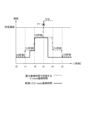
- FIG. 16 is a flowchart of return time determination in the return time determination unit 140. This is a detailed flowchart of "return time determination" in step S103 of FIGS. 12 and 13. This flow is a method of determining the maximum return time using the actually measured C-state return time.
- the return time determination unit 140 determines (C-state return time allowed by the maximum return time + one step deeper C-state) in step S22. It is determined whether the increment of return time) is smaller than the allowable delay time.
- step S23 the return time determination unit 140 determines time slot #n The process of this flow is ended by setting the maximum return time at +1 + the increment of the return time at a C-state one step deeper (permissible C-state + 1).
- step S21 If the C-state is not the C-state that allows the maximum return time in step S21 (S21: No), it is determined that the return time is shortened, and in step S24 the return time determination unit 140 determines the maximum return time in time slot #n+1.
- the return time difference (acceptable C-state - 1) in the C-state one level shallower is set, and the processing of this flow is ended.
- step S22 if (C-state return time allowed by maximum return time + increment of return time in one step deeper C-state) ⁇ allowable delay time (S22: No), in step S25, the return time determining unit 140: The process of this flow is ended with no correction of the maximum return time.
- FIG. 17 is a diagram showing an example of the operation when the maximum return time determination process of FIG. 16 is executed.
- the vertical axis in FIG. 17 shows the allowable delay, and the horizontal axis shows time.
- the broken line in FIG. 17 shows the C-state return time allowed by the maximum return time
- the solid line in FIG. 17 shows the actually measured C-state return time.
- FIG. 17 shows an example in which the target C-state C3 in time slot t3 is not allowed because it exceeds the allowable delay (code oo in FIG. 17).
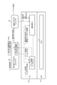
- the task scheduler device 100 (FIG. 1) according to the above embodiment is realized, for example, by a computer 900 having a configuration as shown in FIG. 18.
- FIG. 18 is a hardware configuration diagram showing an example of a computer 900 that implements the functions of the task scheduler device 100 (FIG. 1).
- the computer 900 has a CPU 901, a ROM 902, a RAM 903, an HDD 904, a communication interface (I/F) 906, an input/output interface (I/F) 905, and a media interface (I/F) 907.
- the CPU 901 operates based on a program stored in the ROM 902 or HDD 904, and controls each part of the task scheduler device 100 (FIG. 1).
- the ROM 902 stores a boot program executed by the CPU 901 when the computer 900 is started, programs depending on the hardware of the computer 900, and the like.
- the CPU 901 controls an input device 910 such as a mouse and a keyboard, and an output device 911 such as a display via an input/output I/F 905.
- the CPU 901 acquires data from the input device 910 via the input/output I/F 905 and outputs the generated data to the output device 911.
- a GPU Graphics Processing Unit
- a GPU Graphics Processing Unit
- the HDD 904 stores programs executed by the CPU 901 and data used by the programs.
- the communication I/F 906 receives data from other devices via a communication network (for example, NW (Network) 922) and outputs it to the CPU 901, and also sends data generated by the CPU 901 to other devices via the communication network. Send to device.
- NW Network
- the media I/F 907 reads the program or data stored in the recording medium 912 and outputs it to the CPU 901 via the RAM 903.
- the CPU 901 loads a program related to target processing from the recording medium 912 onto the RAM 903 via the media I/F 907, and executes the loaded program.
- the recording medium 912 is an optical recording medium such as a DVD (Digital Versatile Disc) or a PD (Phase change rewritable disk), a magneto-optical recording medium such as an MO (Magneto Optical disk), a magnetic recording medium, a conductive memory tape medium, a semiconductor memory, or the like. It is.
- the CPU 901 of the computer 900 executes the task scheduler device by executing a program loaded on the RAM 903. Realizes 100 functions. Furthermore, data in the RAM 903 is stored in the HDD 904 .
- the CPU 901 reads a program related to target processing from the recording medium 912 and executes it. In addition, the CPU 901 may read a program related to target processing from another device via a communication network (NW 922).
- NW 922 a communication network
- the computer system 1000 has a processor consisting of a plurality of cores, and in which a process runs that executes a predetermined instruction using the time on the processor, and the process does not receive notifications.
- a standby process 101 (FIGS. 5 and 7) that remains in a standby state until a notification occurs and resumes operation when a notification is received; and a notification process 90 that sends a notification to wake up the standby process when an event occurs.
- the standby process 101 includes a pseudo idle task 103 (FIGS. 5 and 7) that continues to monopolize the processor when in the standby state.
- the computer system 1000 can cause the standby process 101 to behave in the same way as the idle task 92 (FIGS. 4 and 6) that occurs when there is no process on the processor and does nothing.
- the idle task 92 is not scheduled, and therefore the standby process processing is resumed without a context switch occurring. That is, the pseudo idle task 103 causes the standby process 101 to behave in the same way as the idle task 92, and eliminates context switches from the idle task 92. Therefore, the time required for the standby process to wake up after an event occurs can be reduced.
- the pseudo idle task 103 (FIGS. 5 and 7) is characterized by causing the processor to execute a sleep instruction.
- the pseudo idle task 103 can cause the CPU to execute the sleep (NOP) instruction. That is, the pseudo-idle task 103 maintains a sleep state in which it does not execute anything, and calls and executes the c-state control unit 62 (FIG. 1) that controls the operating state of the CPU instead of the idle unit 51 (FIG. 1). . This makes it possible to reduce CPU cycles and suppress power consumption of the corresponding CPU core.
- NOP sleep
- a task scheduler device 100 that schedules processes in a computer system 1000 (FIG. 1) that has a processor consisting of a plurality of cores and runs a process that executes a predetermined instruction using time on the processor.
- the standby process 101 (FIGS. 5 and 7) remains in a standby state until a notification is received and wakes up and resumes operation when there is a notification.
- a pseudo idle task 103 (FIGS. 5 and 7) that continues to exclusively occupy the processor is provided.
- the task scheduler device 100 restarts the standby process processing without generating a context switch, so it is possible to minimize the time it takes for the standby process to wake up after an event occurs.
- the pseudo idle task 103 (FIGS. 5 and 7) is characterized by causing the processor to execute a sleep instruction.
- the pseudo idle task 103 can cause the CPU to execute the sleep (NOP) instruction. This makes it possible to reduce CPU cycles and suppress power consumption of the corresponding CPU core.
- NOP sleep
- the task scheduler device 100 includes a pseudo-idle determination unit 130 that determines whether to execute a pseudo-idle task 103 based on the process occurrence state on the same processor and/or delay time requirements. It is characterized by
- the pseudo idle task 103 can be executed under appropriate conditions based on the process occurrence state on the processor and the delay time requirements. Since it has the effect of the pseudo-idle task 103 and is executed only under conditions that do not affect other processes, it is possible to achieve the effects of "eliminating context switches due to processor occupancy" and "executing the sleep instruction". .
- a return time setting unit sets a return time until the pseudo idle task 103 (FIGS. 5 and 7) returns after task generation. ).
- the task scheduler device 100 can shorten the delay time until the standby process (standby function) wakes up.
- the return time control unit (return time determination unit 140 and return time setting unit 150) overwrites the determined return time with the maximum return time and shortens the maximum return time. It is characterized by not transitioning to a deep sleep state.
- the task scheduler device 100 can shorten the delay time until the standby process (standby function) wakes up. Therefore, ⁇ Requirement 1: Reduction of notification time> can be satisfied. Furthermore, by increasing the maximum return time, the task scheduler device 100 can transition to a deep sleep state and reduce power consumption in the HW, thereby satisfying ⁇ Requirement 2: Power saving>.
- each of the above-mentioned configurations, functions, processing units, processing means, etc. may be partially or entirely realized by hardware, for example, by designing an integrated circuit.
- each of the above-mentioned configurations, functions, etc. may be realized by software for a processor to interpret and execute a program for realizing each function.
- Information such as programs, tables, files, etc. that realize each function is stored in memory, storage devices such as hard disks, SSDs (Solid State Drives), IC (Integrated Circuit) cards, SD (Secure Digital) cards, optical disks, etc. It can be held on a recording medium.
- Idle process (idle task) 51 Idol part 60 kernel 61 Scheduler 62 C-state control section 90 Notification process 92 Idle task 100 Task scheduler device 101 Standby process 103 Pseudo idle task 110 Standby section 120 Pseudo idle section 130 Pseudo idle judgment section 140 Return time determination section (return time control section) 150 Return time setting section (return time control section) 1000 Computer system CPUcore #m, CPUcore #n,... CPU core
Landscapes
- Engineering & Computer Science (AREA)
- Software Systems (AREA)
- Theoretical Computer Science (AREA)
- Physics & Mathematics (AREA)
- General Engineering & Computer Science (AREA)
- General Physics & Mathematics (AREA)
- Debugging And Monitoring (AREA)
Abstract
The present invention is a computer system (1000) which has a processor composed of a plurality of cores and in which processes each operate for executing a prescribed command using a time period on the processor. The processes includes: a standby process (101) that is in a standby state until there is a notification and awakens when there is a notification and restarts the operation; and a notification process (90) that transmits a notification for causing awakening from the standby process at an event generation time, wherein the standby process (101) comprises a pseudo idle task (103) that continues to exclusively occupy the processor while in the standby state.
Description
本発明は、計算機システム、タスクスケジューラ装置、待ちプロセス起床方法およびプログラムに関する。
The present invention relates to a computer system, a task scheduler device, a waiting process wake-up method, and a program.
計算機システムにおいて、計算機(以下、サーバ)上に、汎用プロセッサ(CPU)を搭載し、CPU上で動作するプロセスを常に動作させる必要がない場合には該当プロセスを停止状態とし、必要なタイミングで別のプロセスから通知を送ることでプロセスを稼働状態に戻すことがある。
In a computer system, a computer (hereinafter referred to as a server) is equipped with a general-purpose processor (CPU), and if a process running on the CPU does not need to be constantly running, the process is stopped and separated when necessary. A process may be returned to a running state by sending a notification from that process.
図19は、ポーリング方式によるサーバ内のプロセス間通信を示す図である。
図19に示すように、アプリケーション(以下、適宜「APL」という)[A:待ち側]1から、APL[B:通知側]1にタスクの処理を依頼する(S1)。その後、APL[A:待ち側]1は、ポーリングにより処理結果を要求する(S2)。APL[B:通知側]1は、APL[A:待ち側]1から依頼されたタスク処理を実行する(S3)。 FIG. 19 is a diagram showing inter-process communication within the server using the polling method.
As shown in FIG. 19, an application (hereinafter referred to as "APL") [A: waiting side] 1 requests APL [B: notifying side] 1 to process a task (S1). After that, APL [A: waiting side] 1 requests the processing result by polling (S2). APL [B: notification side] 1 executes the task processing requested by APL [A: waiting side] 1 (S3).
APL[B:通知側]1は、依頼されたタスク処理が完了すると、ポーリング要求に応えて処理結果をAPL[A:待ち側]1に送る(S4)。APL[A:待ち側]1は、次の処理を実行する(S5)。
When the requested task processing is completed, APL [B: notification side] 1 sends the processing result to APL [A: waiting side] 1 in response to the polling request (S4). APL [A: Waiting side] 1 executes the following process (S5).
図20は、通知方式によるサーバ内のプロセス間通信を示す図である。図19と同じ処理には同一ステップ番号を付している。
図20に示すように、APL[A:待ち側]1から、APL[B:通知側]1にタスクの処理を依頼する(S1)。APL[A:待ち側]1は、sleep制御を行い、sleep状態に入る(S6)。 FIG. 20 is a diagram showing inter-process communication within the server using the notification method. The same steps as those in FIG. 19 are given the same step numbers.
As shown in FIG. 20, APL [A: waiting side] 1 requests APL [B: notifying side] 1 to process a task (S1). APL [A: waiting side] 1 performs sleep control and enters a sleep state (S6).
APL[B:通知側]1は、APL[A:待ち側]1から依頼されたタスク処理を実行する(S3)。
APL[B:通知側]1は、依頼されたタスク処理が完了すると、APL[A:待ち側]1に処理完了を通知する(S7)。 APL [B: notification side] 1 executes the task processing requested by APL [A: waiting side] 1 (S3).
When the requested task processing is completed, APL [B: notification side] 1 notifies APL [A: waiting side] 1 of the completion of the process (S7).
APL[A:待ち側]1は、APL[B:通知側]1からの処理完了通知を受けて(S7)、sleep状態から起床し、APL[B:通知側]1に処理結果を要求する(S8)。
APL[B:通知側]1は、APL[A:待ち側]1からの結果要求を受けて、APL[A:待ち側]1に処理結果を送る(S4)。APL[A:待ち側]1は、次の処理を実行する(S5)。 APL [A: Waiting side] 1 receives the processing completion notification from APL [B: Notifying side] 1 (S7), wakes up from the sleep state, and requests the processing result from APL [B: Notifying side] 1. (S8).
APL [B: notification side] 1 receives the result request from APL [A: wait side] 1, and sends the processing result to APL [A: wait side] 1 (S4). APL [A: Waiting side] 1 executes the following process (S5).
図19のポーリング方式では、例えば、あるプロセスAが別のプロセスBにタスクの処理を依頼し、プロセスBにおけるタスク処理が完了するまでの間、完了しているかをポーリングする。プロセスAが稼働状態であり、消費電力が上がってしまう。
図20の通知方式では、プロセスBにタスクの処理を依頼し終わった後に、プロセスAがsleep状態に入るsleep制御が採られる。プロセスAかsleep状態に入るので、消費電力を低減することができる。プロセスAがsleep状態に入ると、プロセスBが処理完了をプロセスAに通知し、通知を受けたプロセスAがsleepから起床し処理完了後のタスクをプロセスBに対して要求することが行われる。しかし、プロセスAはsleepから起床するので、復帰のための遅延時間が発生する。 In the polling method shown in FIG. 19, for example, a process A requests another process B to process a task, and polls until the task process in process B is completed to see if it has been completed. Process A is in operation and power consumption increases.
In the notification method shown in FIG. 20, sleep control is adopted in which process A enters a sleep state after requesting process B to process a task. Since process A enters the sleep state, power consumption can be reduced. When process A enters the sleep state, process B notifies process A of the completion of processing, and process A that receives the notification wakes up from sleep and requests process B to complete the task. However, since process A wakes up from sleep, a delay time occurs for recovery.
同一サーバ内のプロセス間で高速にこのような通知を行うためには、互いに共有したファイルディスクリプタ等のリソースを通じて通知を行うことが一般的である。しかし、プロセスが停止状態から復帰するまではOSのスケジューラ(Scheduler)やガバナー(Governor)によって管理されるため、ユーザが予期せぬ遅延時間がかかる可能性がある。
In order to perform such notifications quickly between processes within the same server, it is common to perform notifications through mutually shared resources such as file descriptors. However, since the process is managed by the OS's scheduler and governor until it returns from the stopped state, there is a possibility that a delay time that the user does not expect may occur.
既存技術として、Linux OS(登録商標)の中の関数「eventfd+epoll_wait」を用いた通知機構がある。
図21は、eventfd+epoll_waitを用いた通知システムを示す図である。
図21に示すように、サーバは、ハードウェア(HW)10と、OS20と、ユーザ空間上に、待ち受けプロセス[core #n]30と、通知プロセス[core #m]32とを有する。待ち受けプロセス[core #n]30は、図20では、APL[A:待ち側]1の「プロセスA」であり、通知プロセス[core #m]32は、APL[B:通知側]1の「プロセスB」である。 As an existing technology, there is a notification mechanism using the function "eventfd+epoll_wait" in Linux OS (registered trademark).
FIG. 21 is a diagram showing a notification system using eventfd+epoll_wait.
As shown in FIG. 21, the server includes hardware (HW) 10, anOS 20, a standby process [core #n] 30, and a notification process [core #m] 32 in the user space. In FIG. 20, the standby process [core #n] 30 is "process A" of APL [A: waiting side] 1, and the notification process [core #m] 32 is "process A" of APL [B: notifying side] 1. Process B.
図21は、eventfd+epoll_waitを用いた通知システムを示す図である。
図21に示すように、サーバは、ハードウェア(HW)10と、OS20と、ユーザ空間上に、待ち受けプロセス[core #n]30と、通知プロセス[core #m]32とを有する。待ち受けプロセス[core #n]30は、図20では、APL[A:待ち側]1の「プロセスA」であり、通知プロセス[core #m]32は、APL[B:通知側]1の「プロセスB」である。 As an existing technology, there is a notification mechanism using the function "eventfd+epoll_wait" in Linux OS (registered trademark).
FIG. 21 is a diagram showing a notification system using eventfd+epoll_wait.
As shown in FIG. 21, the server includes hardware (HW) 10, an
ハードウェア(HW)10は、CPU11を備える。待ち受けプロセス[core #n]30は、待ち受け関数31を有する。
OS20は、イベント監視インスタンス21と、通知用FD(File Descriptor)22と、を有する。通知用FD22は、OS20にアクセスを依頼する際にファイルを指定する整数値である。プログラムからファイルを操作する際、操作対象のファイルを識別・(以下、「・」は「および」を表わす)同定するために割り当てられる。 The hardware (HW) 10 includes aCPU 11. The standby process [core #n] 30 has a standby function 31 .
TheOS 20 includes an event monitoring instance 21 and a notification FD (File Descriptor) 22. The notification FD 22 is an integer value that specifies a file when requesting access to the OS 20. When operating a file from a program, it is assigned to identify the file to be operated (hereinafter, "." represents "and").
OS20は、イベント監視インスタンス21と、通知用FD(File Descriptor)22と、を有する。通知用FD22は、OS20にアクセスを依頼する際にファイルを指定する整数値である。プログラムからファイルを操作する際、操作対象のファイルを識別・(以下、「・」は「および」を表わす)同定するために割り当てられる。 The hardware (HW) 10 includes a
The
既存技術では、図21中の1.~9.の流れで通知と起床を行う。
1.待ち受けプロセス30(「プロセスA」)が、イベント監視インスタンス21(eventpoll)を作成する。
2.待ち受けプロセス30が、通知用に使うFDである通知用FD22(eventfd)を作成し、上記1.のイベント監視インスタンス21に登録する。
3.待ち受けプロセス30が、通知プロセス32(「プロセスB」)に対して通知用FD22を転送する。これにより、待ち受けプロセス30(「プロセスA」)と通知プロセス32(「プロセスB」)間で、この通知用FD22を使うことが合意される。 In the existing technology, 1. in FIG. ~9. Notify and wake up according to the flow.
1. A standby process 30 (“process A”) creates an event monitoring instance 21 (eventpoll).
2. Thestandby process 30 creates a notification FD 22 (eventfd), which is an FD used for notifications, and performs the above 1. to the event monitoring instance 21 of.
3. Thestandby process 30 transfers the notification FD 22 to the notification process 32 ("process B"). As a result, an agreement is reached between the standby process 30 ("process A") and the notification process 32 ("process B") to use this notification FD 22.
1.待ち受けプロセス30(「プロセスA」)が、イベント監視インスタンス21(eventpoll)を作成する。
2.待ち受けプロセス30が、通知用に使うFDである通知用FD22(eventfd)を作成し、上記1.のイベント監視インスタンス21に登録する。
3.待ち受けプロセス30が、通知プロセス32(「プロセスB」)に対して通知用FD22を転送する。これにより、待ち受けプロセス30(「プロセスA」)と通知プロセス32(「プロセスB」)間で、この通知用FD22を使うことが合意される。 In the existing technology, 1. in FIG. ~9. Notify and wake up according to the flow.
1. A standby process 30 (“process A”) creates an event monitoring instance 21 (eventpoll).
2. The
3. The
4.待ち受けプロセス30が、上記1.のイベント監視インスタンス21を指定して待ち受け関数31(epoll_wait)を発行し、ブロッキング(sleep)状態となる。待ち受け関数31(epoll_wait)を発行すると、待ち受けプロセス30は、イベントが発行されるまでは、sleep状態となる。待ち受けプロセス30自体は、sleep状態になるが、該当CPUコアの上に他になにもプロセスが乗っていない状態、すなわちidle状態に相当する場合には、待ち受けプロセス30がsleepに入ったときには、アイドルタスクが出現する。このアイドルタスクは、CPUコアが何もしない状態ではあるものの、プロセスがないときには自動的に出現する。
4. The standby process 30 performs the above 1. It specifies the event monitoring instance 21, issues the wait function 31 (epoll_wait), and enters a blocking (sleep) state. When the standby function 31 (epoll_wait) is issued, the standby process 30 enters a sleep state until an event is issued. The standby process 30 itself goes into a sleep state, but if there is no other process on the corresponding CPU core, which corresponds to an idle state, when the standby process 30 goes into a sleep state, An idle task will appear. This idle task is a state in which the CPU core does nothing, but automatically appears when there are no processes.
5.<イベント発生>
6.通知プロセス32が、イベント発生を検知して、通知用FD22に書き込む。
7.通知用FD22に書き込みを行うと、イベント監視コールバックが走る(発生する)。
8.イベント監視コールバックが発生すると、イベント監視インスタンス21を待ち受けている待ち受け関数31に指示がいく。指定を受けた待ち受け関数31は、イベントを検知して起床する。
9.待ち受け関数31を呼び出した待ち受けプロセス30は、処理を再開する。
なお、上記2.の通知用FD作成は、通知プロセス32側で実行するケースもある。 5. <Event occurrence>
6. Thenotification process 32 detects the occurrence of an event and writes it to the notification FD 22.
7. When writing is performed to thenotification FD 22, an event monitoring callback is executed (occurs).
8. When an event monitoring callback occurs, an instruction is sent to thestandby function 31 that is waiting for the event monitoring instance 21. The designated standby function 31 detects the event and wakes up.
9. Thestandby process 30 that called the standby function 31 resumes processing.
In addition, above 2. In some cases, the notification FD creation is executed on thenotification process 32 side.
6.通知プロセス32が、イベント発生を検知して、通知用FD22に書き込む。
7.通知用FD22に書き込みを行うと、イベント監視コールバックが走る(発生する)。
8.イベント監視コールバックが発生すると、イベント監視インスタンス21を待ち受けている待ち受け関数31に指示がいく。指定を受けた待ち受け関数31は、イベントを検知して起床する。
9.待ち受け関数31を呼び出した待ち受けプロセス30は、処理を再開する。
なお、上記2.の通知用FD作成は、通知プロセス32側で実行するケースもある。 5. <Event occurrence>
6. The
7. When writing is performed to the
8. When an event monitoring callback occurs, an instruction is sent to the
9. The
In addition, above 2. In some cases, the notification FD creation is executed on the
既存技術についてさらに説明する。
図22は、非特許文献1に記載の既存技術の待ち受けプロセスを説明する図である。
図22に示すように、待ち受けプロセス40は、待ち受け部41と、sleep部42を有し、アイドルプロセス50(アイドルタスク)は、アイドル部51を有する。また、OSのkernel60は、スケジューラ61と、C-state制御部62と、を有する(C-stateについては後記)。
アイドルプロセス50は、当該CPUコア上に他のプロセス(スレッド)が存在するとなくなる。 Existing technology will be further explained.
FIG. 22 is a diagram illustrating the standby process of the existing technology described inNon-Patent Document 1.
As shown in FIG. 22, thestandby process 40 has a standby section 41 and a sleep section 42, and the idle process 50 (idle task) has an idle section 51. Further, the OS kernel 60 includes a scheduler 61 and a C-state control unit 62 (C-state will be described later).
Theidle process 50 disappears when another process (thread) exists on the CPU core.
図22は、非特許文献1に記載の既存技術の待ち受けプロセスを説明する図である。
図22に示すように、待ち受けプロセス40は、待ち受け部41と、sleep部42を有し、アイドルプロセス50(アイドルタスク)は、アイドル部51を有する。また、OSのkernel60は、スケジューラ61と、C-state制御部62と、を有する(C-stateについては後記)。
アイドルプロセス50は、当該CPUコア上に他のプロセス(スレッド)が存在するとなくなる。 Existing technology will be further explained.
FIG. 22 is a diagram illustrating the standby process of the existing technology described in
As shown in FIG. 22, the
The
既存技術の省電力化方法では、待ち受け部41がsleep部42を呼び出し、プロセス(待ち受けプロセス40)が待ち状態に入る。スケジューラ61は、ほかに実行可能状態のプロセスがない場合、アイドル部51を持つプロセスを呼び出す。アイドル部51は、C-state制御部62を用いてCPUをsleep状態へ遷移させる、または電力をOFFする。
In the power saving method of the existing technology, the standby unit 41 calls the sleep unit 42, and the process (standby process 40) enters the standby state. The scheduler 61 calls the process having the idle part 51 if there is no other process in an executable state. The idle unit 51 uses the C-state control unit 62 to transition the CPU to a sleep state or turn off the power.
既存技術では、コンテキストスイッチ(context switch)が必ず発生する。コンテキストスイッチは、複数のプロセスが1つのCPUを共有できるように、CPUの状態(コンテキスト)を保存/(以下、「/」は「または」を表わす)復元する過程をいう。
With existing technology, a context switch always occurs. Context switching refers to the process of saving/restoring the state (context) of a CPU (hereinafter, "/" represents "or") so that multiple processes can share one CPU.
既存技術では、C-state復帰時間は、kernelが決定する。kernelは、C-state制御部62が推測したアイドル時間をもとにC-stateの深さを決定する。該当C-stateからの復帰時間が発生する(非特許文献2)。
In existing technology, the C-state return time is determined by the kernel. The kernel determines the depth of the C-state based on the idle time estimated by the C-state control unit 62. There is a time required to return from the corresponding C-state (Non-Patent Document 2).
図23は、C-stateの状態の一例を表にして示す図である。なお、CPUハードウェアに依って状態定義は異なるため、図23はあくまでも参考例である。
図23に示すように、CPUidle状態には、グレードC0~C6があり、CPUの負荷がない時間が長くなるにつれ、深いsleep状態へ遷移する。深いsleep状態の方がCPU消費電力は小さくなるが、一方で、それだけ復帰までに要する時間が長延化するため、低遅延の観点で課題となる場合がある。 FIG. 23 is a diagram showing an example of C-state states in a table. Note that since the state definition differs depending on the CPU hardware, FIG. 23 is just a reference example.
As shown in FIG. 23, the CPUidle state has grades C0 to C6, and as the time when the CPU is not loaded increases, the state transitions to a deep sleep state. A deep sleep state consumes less CPU power, but on the other hand, it lengthens the time it takes to return, which may pose a problem in terms of low latency.
C-stateは、CPUハードウェアに依って状態定義が異なる。例えば、C4やC5が無い機種、C1の次がC1Eというステートである機種等のバリエーションがある。
ステートが深くなるにつれ省電力効果は大きくなるが、それだけ、idle状態から復帰に要する時間も大きくなる。 The state definition of C-state differs depending on the CPU hardware. For example, there are variations such as a model without C4 or C5, and a model in which the state following C1 is C1E.
As the state becomes deeper, the power saving effect increases, but the time required to return from the idle state also increases.
また、どの深さまでCPUidle状態が遷移するかは、CPUのハードウェア制御になり、CPU製品依存となる(kernel等のソフトウェアから制御できない場合が多い)。
Furthermore, the depth to which the CPUidle state transitions is controlled by the CPU hardware and depends on the CPU product (in many cases, it cannot be controlled from software such as the kernel).
既存技術では、遅延時間増大する課題がある。
(1)コンテキストスイッチ時間による遅延時間増大
図24は、既存技術の課題を説明する図である。
図24の下段は、待ち受けプロセス(core #n)のスケジュール、図24の上段は、通知プロセス(core #m)のスケジュールである。
下記1.~3.を初期化時に実行済みであるとする。
1.イベント監視インスタンス作成
2.通知用FD作成・イベント監視インスタンス登録
3.通知用FD転送 Existing technology has the problem of increased delay time.
(1) Increase in delay time due to context switch time FIG. 24 is a diagram illustrating problems with existing technology.
The lower part of FIG. 24 shows the schedule of the standby process (core #n), and the upper part of FIG. 24 shows the schedule of the notification process (core #m).
Below 1. ~3. Assume that has been executed at initialization.
1. Eventmonitoring instance creation 2. Create notification FD/register event monitoring instance 3. Notification FD transfer
(1)コンテキストスイッチ時間による遅延時間増大
図24は、既存技術の課題を説明する図である。
図24の下段は、待ち受けプロセス(core #n)のスケジュール、図24の上段は、通知プロセス(core #m)のスケジュールである。
下記1.~3.を初期化時に実行済みであるとする。
1.イベント監視インスタンス作成
2.通知用FD作成・イベント監視インスタンス登録
3.通知用FD転送 Existing technology has the problem of increased delay time.
(1) Increase in delay time due to context switch time FIG. 24 is a diagram illustrating problems with existing technology.
The lower part of FIG. 24 shows the schedule of the standby process (core #n), and the upper part of FIG. 24 shows the schedule of the notification process (core #m).
Below 1. ~3. Assume that has been executed at initialization.
1. Event
4.で待ち受けプロセス処理71がsleep状態になると、該当CPUコアに対してはアイドルタスクがスケジュールされる可能性がある。図24では、event receiver (core #n)は、待ち受けプロセス処理71、および待ち受け関数72の実行後、コンテキストスイッチ(図24の符号a)によりアイドルタスク76に移行する。上述したように、待ち受けプロセスがsleep状態になると、該当CPUコアの上に他になにもプロセスが乗っていないidle状態の場合には、アイドルタスク76が出現する。アイドルタスク76が動作することで、CPUコア(event receiver (core #n))は段階的に深いスリープ状態(CPU idle)に落ち、消費電力を削減することが可能になる。
4. When the standby process processing 71 enters the sleep state, an idle task may be scheduled for the corresponding CPU core. In FIG. 24, the event receiver (core #n) transitions to the idle task 76 by a context switch (reference numeral a in FIG. 24) after executing the standby process processing 71 and the standby function 72. As described above, when the standby process enters the sleep state, the idle task 76 appears if the corresponding CPU core is in the idle state with no other processes running on it. When the idle task 76 operates, the CPU core (event receiver (core #n)) falls into a deep sleep state (CPU idle) in stages, making it possible to reduce power consumption.
一方、event sender (core #m)で5.イベント発生すると、6.通知用FD書き込み74により、7.イベント監視コールバック75が実行され、event sender (core #m)は、event receiver (core #n)に対してプロセッサ間割り込み(図24の符号b)を行う。
On the other hand, event sender (core #m) is 5. When an event occurs, 6. By writing to the notification FD 74, 7. The event monitoring callback 75 is executed, and the event sender (core #m) issues an inter-processor interrupt (reference numeral b in FIG. 24) to the event receiver (core #n).
8.で待ち受け関数が起床する際、再度アイドルタスク76がスケジュールされ、その後コンテキストスイッチ(図24の符号c)を経由して待ち受け関数がスケジュールされ、9.待ち受けプロセス処理再開(図24の番号78)となる。
コンテキストスイッチは、一般的に、Kernel spaceで動作している状態と、User spaceで動作している状態とを切替える。
このアイドルタスク76から待ち受け関数起床77へのコンテキストスイッチ(図24の符号c)により、大きな遅延が発生する(図24の☆印d)。すなわち、待ち受け関数に切り替わる際のコンテキストスイッチ時間が発生し、大きな遅延が発生する。 8. When the standby function wakes up in step 9, theidle task 76 is scheduled again, and then the standby function is scheduled via a context switch (reference numeral c in FIG. 24).9. The standby process processing is resumed (number 78 in FIG. 24).
A context switch generally switches between operating in Kernel space and operating in User space.
This context switch from theidle task 76 to the standby function wake-up 77 (sign c in FIG. 24) causes a large delay (marked with ☆ d in FIG. 24). That is, a context switch time occurs when switching to the standby function, resulting in a large delay.
コンテキストスイッチは、一般的に、Kernel spaceで動作している状態と、User spaceで動作している状態とを切替える。
このアイドルタスク76から待ち受け関数起床77へのコンテキストスイッチ(図24の符号c)により、大きな遅延が発生する(図24の☆印d)。すなわち、待ち受け関数に切り替わる際のコンテキストスイッチ時間が発生し、大きな遅延が発生する。 8. When the standby function wakes up in step 9, the
A context switch generally switches between operating in Kernel space and operating in User space.
This context switch from the
(2)sleep状態(C-state)復帰による遅延時間増大
CPUidle状態になると、OSのガバナーによって許容されたsleep状態(C-state)になるまで、CPUは段階的あるいは直接的にsleep状態を遷移させる。
OSのガバナーが、サーバ全体のポリシーとして深いsleep状態を許容する場合(例えば、C6)、CPUの稼働状態(C0)に戻るまでに100us以上の長い復帰時間が発生する。 (2) Increased delay time due to return from sleep state (C-state) Once in the CPUidle state, the CPU transitions from the sleep state in stages or directly until it enters the sleep state (C-state) allowed by the OS governor. let
When the OS governor allows a deep sleep state as a policy for the entire server (for example, C6), a long recovery time of 100 us or more occurs before the CPU returns to the operating state (C0).
図25は、図24のスケジュールに、演算に使用するCPUコアのC-state遷移イメージを重ね合わせて示した図である。
図25に示すように、タスクなし時間が長い場合は、CPUコアが深いsleep状態(CPUidle状態:グレードC6)にあり、タスク発生(図25の符号e)後、復帰までの遅延時間が長延化する。深いCPU idle stateまで落ちると、復帰するまでに大きな時間を要し、リアルタイム性が損なわれるという課題がある。 FIG. 25 is a diagram showing a C-state transition image of a CPU core used for calculations superimposed on the schedule of FIG. 24.
As shown in Figure 25, if the no-task time is long, the CPU core is in a deep sleep state (CPUidle state: grade C6), and the delay time until recovery after a task is generated (code e in Figure 25) is prolonged. do. When the CPU drops to a deep idle state, it takes a long time to recover, which impairs real-time performance.
上記課題は、基地局(BBU)のようにリアルタイム性が最優先されるシステムでは、看過できない問題である。
このため、基地局(BBU)にあっては、C-stateを無効にする、若しくは、idle stateの遷移をC1等の限られた深さに限定する設定を投入する対応が採られる。すなわち、省電力性を犠牲にし、リアルタイム性を指向するチューニングが行われる場合がある。 The above problem cannot be overlooked in a system such as a base station (BBU) where real-time performance is given top priority.
For this reason, the base station (BBU) takes measures such as disabling the C-state or introducing settings that limit the transition of the idle state to a limited depth such as C1. In other words, tuning may be performed in favor of real-time performance at the expense of power saving.
このような背景を鑑みて本発明がなされたのであり、本発明は、イベント発生後に待ち受けプロセスが起床するまでにかかる時間を低減することを課題とする。
The present invention was made in view of this background, and an object of the present invention is to reduce the time required for a standby process to wake up after an event occurs.
前記した課題を解決するため、複数のコアからなるプロセッサを有し、当該プロセッサ上の時間を用いて所定の命令を実行するプロセスが動作する計算機システムであって、前記プロセスは、通知があるまで待ち状態となり、通知がある場合に起床して動作を再開する待ち受けプロセスと、イベント発生時に待ち受けプロセスを起床させるために通知を送信する通知プロセスと、を有し、前記待ち受けプロセスは、待ち受け状態に入っているときに、前記プロセッサを専有し続ける疑似アイドルタスクを有することを特徴とする計算機システムとした。
In order to solve the above-mentioned problems, a computer system is provided that has a processor consisting of multiple cores and runs a process that executes a predetermined instruction using the time on the processor, and the process runs until notified. A standby process that enters a standby state and wakes up and resumes operation when there is a notification, and a notification process that sends a notification to wake up the standby process when an event occurs, and the standby process is set to a standby state. The computer system is characterized in that it has a pseudo-idle task that continues to occupy the processor when the computer is running.
本発明によれば、イベント発生後に待ち受けプロセスが起床するまでにかかる時間を低減することができる。
According to the present invention, it is possible to reduce the time required for a standby process to wake up after an event occurs.
以下、図面を参照して本発明を実施するための形態(以下、「本実施形態」という)における計算機システム等について説明する。
[概要]
図1は、本発明の実施形態に係る計算機システムの概略構成図である。図22と同一構成部分には、同一符号を付している。
本実施形態は、計算機システムとしてCPUに適用した例である。CPU以外にも、GPU(Graphic Processing Unit),FPGA(Field Programmable Gate Array),ASIC(Application Specific Integrated Circuit)等のプロセッサに、idle stateの機能がある場合には、同様に適用可能である。 DESCRIPTION OF THE PREFERRED EMBODIMENTS A computer system and the like in an embodiment of the present invention (hereinafter referred to as "this embodiment") will be described below with reference to the drawings.
[overview]
FIG. 1 is a schematic configuration diagram of a computer system according to an embodiment of the present invention. Components that are the same as those in FIG. 22 are given the same reference numerals.
This embodiment is an example in which the present invention is applied to a CPU as a computer system. In addition to CPUs, the present invention is also applicable to processors such as GPUs (Graphic Processing Units), FPGAs (Field Programmable Gate Arrays), and ASICs (Application Specific Integrated Circuits), if they have an idle state function.
図1に示すように、計算機システム1000は、kernel60と、CPUコア(core #m,core #n,core #x)80と、通知プロセス90と、アイドルプロセス50と、タスクスケジューラ装置100と、を有する。
As shown in FIG. 1, the computer system 1000 includes a kernel 60, CPU cores (core #m, core #n, core #x) 80, a notification process 90, an idle process 50, and a task scheduler device 100. have
kernel60は、スケジューラ61と、C-state制御部62と、eventfd等のfd(file descriptor:ファイル記述子)63と、Unix Domain Socket等のsocket(通信用ソケット)64と、を有する。
The kernel 60 includes a scheduler 61, a C-state control unit 62, an fd (file descriptor) 63 such as eventfd, and a socket (communication socket) 64 such as Unix Domain Socket.
アイドルプロセス50は、アイドル部51を有する。アイドルプロセス50は、待ち受け中において、他のプロセス(スレッド)が該当CPUコアを使用できるようにする。
The idle process 50 has an idle section 51. The idle process 50 allows other processes (threads) to use the corresponding CPU core while it is on standby.
計算機システム1000は、複数のコアからなるプロセッサを有し、当該プロセッサ上の時間を用いて所定の命令を実行するプロセスが動作し、そのプロセスは、通知があるまで待ち状態となり、通知がある場合に起床して動作を再開する待ち受けプロセス101と、イベント発生時に待ち受けプロセスを起床させるために通知を送信する通知プロセス90と、プロセッサ上にプロセスがないとき発生し何も実行しないアイドルプロセス50と、を有する計算機システムである。
The computer system 1000 has a processor consisting of a plurality of cores, and a process that executes a predetermined instruction using the time on the processor runs, and the process is in a waiting state until a notification is received. A standby process 101 that wakes up and resumes operation when an event occurs, a notification process 90 that sends a notification to wake up the standby process when an event occurs, and an idle process 50 that occurs when there is no process on the processor and does not execute anything. This is a computer system with
[タスクスケジューラ装置100]
タスクスケジューラ装置100は、待受部110と、疑似アイドル部120と、疑似アイドル判断部130と、復帰時間決定部140(復帰時間制御部)と、復帰時間設定部150(復帰時間制御部)と、を備える。
上記待受部110および疑似アイドル部120は、待ち受けプロセス101を構成し、アイドルプロセス50(アイドルタスク)のアイドル部51と連携する。
上記疑似アイドル判断部130、復帰時間決定部140、および復帰時間設定部150は、管理部102を構成する。 [Task scheduler device 100]
Thetask scheduler device 100 includes a standby section 110, a pseudo-idle section 120, a pseudo-idle judgment section 130, a return time determination section 140 (return time control section), and a return time setting section 150 (return time control section). , is provided.
Thestandby unit 110 and the pseudo-idle unit 120 constitute the standby process 101, and cooperate with the idle unit 51 of the idle process 50 (idle task).
The pseudo idle determiningsection 130, the return time determining section 140, and the return time setting section 150 constitute the management section 102.
タスクスケジューラ装置100は、待受部110と、疑似アイドル部120と、疑似アイドル判断部130と、復帰時間決定部140(復帰時間制御部)と、復帰時間設定部150(復帰時間制御部)と、を備える。
上記待受部110および疑似アイドル部120は、待ち受けプロセス101を構成し、アイドルプロセス50(アイドルタスク)のアイドル部51と連携する。
上記疑似アイドル判断部130、復帰時間決定部140、および復帰時間設定部150は、管理部102を構成する。 [Task scheduler device 100]
The
The
The pseudo idle determining
待ち受けプロセス101は、通知があるまで待ち状態となり、通知がある場合に起床して動作を再開する。
待受部110は、実行可能状態を維持する。待受部110は、疑似アイドル判断部130からの疑似アイドル機能要求を受けて、待ち受け設定および実行可能状態設定を行う。具体的には、疑似アイドル判断部130の指示により、疑似アイドル部120を実行するか、アイドル機能を持つアイドルプロセスにコンテキストスイッチを行う。 Thestandby process 101 remains in a standby state until a notification is received, and when there is a notification, it wakes up and resumes operation.
Thestandby unit 110 maintains an executable state. The standby unit 110 receives a pseudo-idle function request from the pseudo-idle determining unit 130, and performs a stand-by setting and an executable state setting. Specifically, in response to an instruction from the pseudo-idle determination unit 130, the pseudo-idle unit 120 is executed or a context switch is performed to an idle process having an idle function.
待受部110は、実行可能状態を維持する。待受部110は、疑似アイドル判断部130からの疑似アイドル機能要求を受けて、待ち受け設定および実行可能状態設定を行う。具体的には、疑似アイドル判断部130の指示により、疑似アイドル部120を実行するか、アイドル機能を持つアイドルプロセスにコンテキストスイッチを行う。 The
The
疑似アイドル部120は、何も実行しないsleep(NOP)状態を維持する。疑似アイドル部120は、アイドル部51の代わりにCPUの稼働状態を制御するC-state制御部62を呼び出して実行する。
疑似アイドル部120は、待ち受け状態に入っているときに、待ち受けプロセス101が、プロセッサを専有し続ける疑似アイドルタスク103(図5、図7)を有する。
ここで、Kernelのスケジューラは、イベント発生時に待ち受けプロセス101に実行時間を与える。直前に実行されている疑似アイドルタスク103は待ち受けプロセスの延長で実行されているため、プロセス切替に伴うコンテキストスイッチを排除することができる。 The pseudoidle unit 120 maintains a sleep (NOP) state in which it does not execute anything. The pseudo idle unit 120 calls and executes the C-state control unit 62 that controls the operating state of the CPU instead of the idle unit 51.
Thepseudo-idle unit 120 has a pseudo-idle task 103 (FIGS. 5 and 7) in which the stand-by process 101 continues to monopolize the processor when in the stand-by state.
Here, the Kernel scheduler gives execution time to thestandby process 101 when an event occurs. Since the pseudo idle task 103 that is being executed immediately before is executed as an extension of the standby process, a context switch accompanying process switching can be eliminated.
疑似アイドル部120は、待ち受け状態に入っているときに、待ち受けプロセス101が、プロセッサを専有し続ける疑似アイドルタスク103(図5、図7)を有する。
ここで、Kernelのスケジューラは、イベント発生時に待ち受けプロセス101に実行時間を与える。直前に実行されている疑似アイドルタスク103は待ち受けプロセスの延長で実行されているため、プロセス切替に伴うコンテキストスイッチを排除することができる。 The pseudo
The
Here, the Kernel scheduler gives execution time to the
疑似アイドル判断部130は、同一プロセッサ上のプロセス生起状態、および/または、遅延時間の要件をもとに、疑似アイドル部120(疑似アイドルタスク)を実行するかを決定し、待受部110に指示する。ここで、疑似アイドル部120を実行するかの判断が必要な理由は、図10で後記するように、通知プロセスと待ち受けプロセスが同一CPUコア上で動作している状況などにおいては、疑似アイドル部を動作させてコンテキストスイッチを排除する効果がない上、他のプロセスにも処理遅延増大などの影響を及ぼす可能性があるためである。
The pseudo-idle determining unit 130 determines whether to execute the pseudo-idle unit 120 (pseudo-idle task) based on the process occurrence state on the same processor and/or the delay time requirements, and sends the pseudo-idle task to the standby unit 110. Instruct. Here, the reason why it is necessary to determine whether to execute the pseudo-idle section 120 is that, as will be described later in FIG. This is because it is not effective in eliminating context switches by running , and it may also have an impact on other processes, such as increasing processing delays.
復帰時間決定部140は、遅延時間の要件や現状のC-stateから、疑似アイドル部120が最大で落ちることのできるC-stateに対応する復帰時間を決定する。復帰時間決定部140は、最大復帰時間を復帰時間設定部150に通知する。
The return time determining unit 140 determines the return time corresponding to the C-state in which the pseudo idle unit 120 can fall at maximum, based on the delay time requirements and the current C-state. The return time determining section 140 notifies the return time setting section 150 of the maximum return time.
復帰時間設定部150は、復帰時間決定部140からの最大復帰時間を用いて、C-state制御部62に最大復帰時間を設定する。復帰時間設定部150は、疑似アイドル部120が終了後に再度、元の最大復帰時間に戻す。
The return time setting unit 150 sets the maximum return time in the C-state control unit 62 using the maximum return time from the return time determining unit 140. The return time setting unit 150 returns to the original maximum return time again after the pseudo idle unit 120 ends.
上記、復帰時間決定部140および復帰時間設定部150は、疑似アイドルタスク103がタスク発生後に復帰するまでの復帰時間を設定する復帰時間設定部を構成する。この復帰時間制御部は、決められた復帰時間を最大復帰時間で上書きし、最大復帰時間を短くとることで深いsleep状態へ遷移させない機能部である。
The return time determining section 140 and the return time setting section 150 described above constitute a return time setting section that sets the return time until the pseudo idle task 103 returns after task generation. This return time control unit is a functional unit that overwrites the determined return time with the maximum return time and shortens the maximum return time to prevent transition to a deep sleep state.
以下、上述のように構成された計算機システム1000の動作を説明する。
[タスクスケジューラ装置100動作の基本的な考え方]
特徴<1>:コンテキストスイッチ排除
待ち受けプロセスにアイドルタスクと同じ振る舞いをさせ、アイドルタスクからのコンテキストスイッチを排除する。
待ち受け関数は、そのコンテキストの中でアイドルタスクと同等の動作をするため、既存のアイドルタスクへのコンテキストスイッチが発生しない。これにより、<要件1:通知時間低減>を満たす。
待ち受け関数が動作する間はアイドルタスクと同様に、CPUコアは、深いスリープ状態に落ちることが可能である。これにより、<要件2:省電力性>を満たす。 The operation of thecomputer system 1000 configured as described above will be explained below.
[Basic concept of operation of task scheduler device 100]
Feature <1>: Eliminate context switches Make the standby process behave in the same way as the idle task, and eliminate context switches from the idle task.
Since the standby function operates in the same way as an idle task within its context, a context switch to an existing idle task does not occur. This satisfies <Requirement 1: Reduction of notification time>.
Similar to an idle task, the CPU core can fall into a deep sleep state while the standby function is running. This satisfies <Requirement 2: Power saving>.
[タスクスケジューラ装置100動作の基本的な考え方]
特徴<1>:コンテキストスイッチ排除
待ち受けプロセスにアイドルタスクと同じ振る舞いをさせ、アイドルタスクからのコンテキストスイッチを排除する。
待ち受け関数は、そのコンテキストの中でアイドルタスクと同等の動作をするため、既存のアイドルタスクへのコンテキストスイッチが発生しない。これにより、<要件1:通知時間低減>を満たす。
待ち受け関数が動作する間はアイドルタスクと同様に、CPUコアは、深いスリープ状態に落ちることが可能である。これにより、<要件2:省電力性>を満たす。 The operation of the
[Basic concept of operation of task scheduler device 100]
Feature <1>: Eliminate context switches Make the standby process behave in the same way as the idle task, and eliminate context switches from the idle task.
Since the standby function operates in the same way as an idle task within its context, a context switch to an existing idle task does not occur. This satisfies <Requirement 1: Reduction of notification time>.
Similar to an idle task, the CPU core can fall into a deep sleep state while the standby function is running. This satisfies <Requirement 2: Power saving>.
図2は、コンテキストスイッチ排除(特徴<1>)を説明する図である。図24と同じプロセスには、同一符号を付している。
図2の下段は、event receiver (core #n)のスケジュール、図2の上段は、event sender (core #m)のスケジュールである。
下記1.~3.を初期化時に実行済みであるとする。
1.イベント監視インスタンス作成
2.通知用FD作成・イベント監視インスタンス登録
3.通知用FD転送 FIG. 2 is a diagram illustrating context switch exclusion (feature <1>). The same processes as in FIG. 24 are given the same reference numerals.
The lower part of FIG. 2 shows the schedule of the event receiver (core #n), and the upper part of FIG. 2 shows the schedule of the event sender (core #m).
Below 1. ~3. Assume that has been executed at initialization.
1. Eventmonitoring instance creation 2. Create notification FD/register event monitoring instance 3. Notification FD transfer
図2の下段は、event receiver (core #n)のスケジュール、図2の上段は、event sender (core #m)のスケジュールである。
下記1.~3.を初期化時に実行済みであるとする。
1.イベント監視インスタンス作成
2.通知用FD作成・イベント監視インスタンス登録
3.通知用FD転送 FIG. 2 is a diagram illustrating context switch exclusion (feature <1>). The same processes as in FIG. 24 are given the same reference numerals.
The lower part of FIG. 2 shows the schedule of the event receiver (core #n), and the upper part of FIG. 2 shows the schedule of the event sender (core #m).
Below 1. ~3. Assume that has been executed at initialization.
1. Event
event receiver (core #n)は、待ち受けプロセス処理71後、アイドルタスクへ遷移させずに(コンテキストスイッチを発生させずに)(図2の符号aa)、4.待ち受け関数・8.待ち受け関数起床201となる。すなわち、待ち受け関数・待ち受け関数起床201では、4.待ち受け関数がアイドルタスクと同等にふるまう(図2の符号bb)。
After the standby process processing 71, the event receiver (core #n) executes the process without transitioning to the idle task (without generating a context switch) (symbol aa in FIG. 2); 4. Standby function・8. The standby function wakes up 201. That is, in the standby function/standby function wake-up 201, 4. The standby function behaves in the same way as an idle task (symbol bb in FIG. 2).
一方、event sender (core #m)で5.イベント発生すると、6.通知用FD書き込み74により、7.イベント監視コールバック75が実行され、event sender (core #m)は、event receiver (core #n)に対してプロセッサ間割り込み(図2の符号b)を行う。
On the other hand, event sender (core #m) is 5. When an event occurs, 6. By writing to the notification FD 74, 7. The event monitoring callback 75 is executed, and the event sender (core #m) issues an inter-processor interrupt (reference numeral b in FIG. 2) to the event receiver (core #n).
4.待ち受け関数がアイドルタスクと同等にふるまうので、8.待ち受け関数起床の際、アイドルタスクのスケジュールが行われず、従ってコンテキストスイッチ(図2の符号cc)は発生せずに、9.待ち受けプロセス処理再開78となる。
4. 8. The standby function behaves the same as an idle task. 9. When the standby function wakes up, the idle task is not scheduled, so a context switch (symbol cc in FIG. 2) does not occur. The standby process process resumes 78.
待ち受け関数は、そのコンテキストの中でアイドルタスクと同等の動作をするため、既存のアイドルタスクへのコンテキストスイッチ(図24の符号c)が発生しない。これにより、<要件1:通知時間低減>を満たすことができる。
ここで、図2には示されていないが、待ち受け関数が動作する間はアイドルタスク(図24の番号76)と同様に、CPUコアは、深いスリープ状態に落ちることが可能である。これにより、<要件2:省電力性>を満たすことができる。 Since the standby function operates in the same way as an idle task within its context, a context switch to an existing idle task (reference numeral c in FIG. 24) does not occur. This makes it possible to satisfy <Requirement 1: Reduction of notification time>.
Although not shown in FIG. 2, while the standby function is operating, the CPU core can fall into a deep sleep state, similar to the idle task (number 76 in FIG. 24). Thereby, <Requirement 2: Power saving> can be satisfied.
ここで、図2には示されていないが、待ち受け関数が動作する間はアイドルタスク(図24の番号76)と同様に、CPUコアは、深いスリープ状態に落ちることが可能である。これにより、<要件2:省電力性>を満たすことができる。 Since the standby function operates in the same way as an idle task within its context, a context switch to an existing idle task (reference numeral c in FIG. 24) does not occur. This makes it possible to satisfy <Requirement 1: Reduction of notification time>.
Although not shown in FIG. 2, while the standby function is operating, the CPU core can fall into a deep sleep state, similar to the idle task (
特徴<2>:疑似アイドルタスクの復帰時間指定
疑似アイドルタスクの最大の復帰時間を指定し、深いsleep状態に落ちないように制御する。
OSのガバナーによって決められた復帰時間を最大復帰時間で上書きし、最大復帰時間を短くとる。これにより、計算機システムは、深いsleep状態へ遷移しないため、待ち受け関数起床までの遅延時間を短くすることが可能である。これにより、<要件1:通知時間低減>を満たす。
一方、最大復帰時間を長くとることで、深いsleep状態へ遷移させ、HWにおいて電力をより削減することが可能である。これにより、<要件2:省電力性>を満たす。 Feature <2>: Specify the return time of the pseudo idle task Specify the maximum return time of the pseudo idle task and control it so that it does not fall into a deep sleep state.
The return time determined by the OS governor is overwritten with the maximum return time to shorten the maximum return time. Thereby, the computer system does not transition to a deep sleep state, so it is possible to shorten the delay time until the standby function wakes up. This satisfies <Requirement 1: Reduction of notification time>.
On the other hand, by increasing the maximum return time, it is possible to transition to a deep sleep state and further reduce power consumption in the HW. This satisfies <Requirement 2: Power saving>.
図3は、図2のスケジュールに、演算に使用するCPUコアのC-state遷移イメージを重ね合わせて示した図である。図25と同じプロセスには、同一符号を付している。
図3に示すように、タスク発生(図3の符号dd)から復帰までの復帰時間最大値(図3の符号ee)を指定する。このような復帰時間最大値指定が可能になるのは、待ち受け関数がアイドルタスクと同等にふるまうようにした待ち受け関数・待ち受け関数起床201を設け、この待ち受け関数・待ち受け関数起床201のスケジュールに自由度を持たすことができるからである。
上記復帰時間最大値指定について、最大復帰時間を短く設定する場合は、CPUコアは浅いsleep状態に落ちるので、電力削減は小さい。また、最大復帰時間を長く設定する場合は、深いsleep状態に落ちるので、電力削減は大きい。ただし、CPUコアが深いsleep状態まで落ちると、復帰するまで時間を要する。 FIG. 3 is a diagram showing a C-state transition image of a CPU core used for calculations superimposed on the schedule of FIG. 2. The same processes as in FIG. 25 are given the same reference numerals.
As shown in FIG. 3, the maximum return time (sign ee in FIG. 3) from task generation (code dd in FIG. 3) to recovery is specified. The reason why such a maximum return time can be specified is that a standby function/standby function wake-up 201 is provided so that the stand-by function behaves in the same way as an idle task, and the schedule of this stand-by function/standby function wake-up 201 is flexible. This is because it is possible to have
Regarding the above specification of the maximum return time, if the maximum return time is set short, the CPU core falls into a shallow sleep state, so the power reduction is small. Also, if you set the maximum return time to be long, the device will fall into a deep sleep state, resulting in a large power reduction. However, once the CPU core falls into a deep sleep state, it takes time to recover.
図3に示すように、タスク発生(図3の符号dd)から復帰までの復帰時間最大値(図3の符号ee)を指定する。このような復帰時間最大値指定が可能になるのは、待ち受け関数がアイドルタスクと同等にふるまうようにした待ち受け関数・待ち受け関数起床201を設け、この待ち受け関数・待ち受け関数起床201のスケジュールに自由度を持たすことができるからである。
上記復帰時間最大値指定について、最大復帰時間を短く設定する場合は、CPUコアは浅いsleep状態に落ちるので、電力削減は小さい。また、最大復帰時間を長く設定する場合は、深いsleep状態に落ちるので、電力削減は大きい。ただし、CPUコアが深いsleep状態まで落ちると、復帰するまで時間を要する。 FIG. 3 is a diagram showing a C-state transition image of a CPU core used for calculations superimposed on the schedule of FIG. 2. The same processes as in FIG. 25 are given the same reference numerals.
As shown in FIG. 3, the maximum return time (sign ee in FIG. 3) from task generation (code dd in FIG. 3) to recovery is specified. The reason why such a maximum return time can be specified is that a standby function/standby function wake-
Regarding the above specification of the maximum return time, if the maximum return time is set short, the CPU core falls into a shallow sleep state, so the power reduction is small. Also, if you set the maximum return time to be long, the device will fall into a deep sleep state, resulting in a large power reduction. However, once the CPU core falls into a deep sleep state, it takes time to recover.
[タスクスケジューラ装置100動作]
[動作1]
タスクスケジューラ装置100の動作1について、比較例(既存技術)と対比しながら説明する。
まず、比較例(既存技術)の動作について述べる。
図4は、比較例における<待ち受け開始時>、<待ち受け中>および<イベント発生時>の待ち受けプロセスの挙動を示す図である。図1と同一構成・プロセスには同じ符号を付している。 [Operation of task scheduler device 100]
[Operation 1]
Operation 1 of the task scheduler device 100 will be described in comparison with a comparative example (existing technology).
First, the operation of a comparative example (existing technology) will be described.
FIG. 4 is a diagram showing the behavior of the standby process at <at the start of standby>, <during standby>, and <at the time of event occurrence> in the comparative example. The same configurations and processes as in FIG. 1 are given the same reference numerals.
[動作1]
タスクスケジューラ装置100の動作1について、比較例(既存技術)と対比しながら説明する。
まず、比較例(既存技術)の動作について述べる。
図4は、比較例における<待ち受け開始時>、<待ち受け中>および<イベント発生時>の待ち受けプロセスの挙動を示す図である。図1と同一構成・プロセスには同じ符号を付している。 [Operation of task scheduler device 100]
[Operation 1]
First, the operation of a comparative example (existing technology) will be described.
FIG. 4 is a diagram showing the behavior of the standby process at <at the start of standby>, <during standby>, and <at the time of event occurrence> in the comparative example. The same configurations and processes as in FIG. 1 are given the same reference numerals.
<待ち受け開始時>
サーバは、CPUコア80(event receiver (core #n))と、CPUコア80(event sender (core #m))とを有する。待ち受け開始時、待ち受けプロセス91は、CPUコア80(core #n)上で、タスクキュー85に入っている。 <When starting standby>
The server includes a CPU core 80 (event receiver (core #n)) and a CPU core 80 (event sender (core #m)). At the start of standby, thestandby process 91 is in the task queue 85 on the CPU core 80 (core #n).
サーバは、CPUコア80(event receiver (core #n))と、CPUコア80(event sender (core #m))とを有する。待ち受け開始時、待ち受けプロセス91は、CPUコア80(core #n)上で、タスクキュー85に入っている。 <When starting standby>
The server includes a CPU core 80 (event receiver (core #n)) and a CPU core 80 (event sender (core #m)). At the start of standby, the
<待ち受け中>
いわゆる待ち状態とは、CPUコア80(core #n)上で、待ち受けプロセス91が、待ちキュー86の中に入ることをいう。
待ち受け中は、待ち受けプロセス91は、タスクキュー85から抜け(図4の矢印f)、図4の右側の待ちキュー86に入り待ち状態となる。 <Standby>
The so-called waiting state means that the waitingprocess 91 enters the waiting queue 86 on the CPU core 80 (core #n).
During standby, thestandby process 91 leaves the task queue 85 (arrow f in FIG. 4), enters the wait queue 86 on the right side of FIG. 4, and enters the wait state.
いわゆる待ち状態とは、CPUコア80(core #n)上で、待ち受けプロセス91が、待ちキュー86の中に入ることをいう。
待ち受け中は、待ち受けプロセス91は、タスクキュー85から抜け(図4の矢印f)、図4の右側の待ちキュー86に入り待ち状態となる。 <Standby>
The so-called waiting state means that the waiting
During standby, the
ここで、CPUコア80(core #n)の上に他になにもプロセスが乗っていない状態、すなわちidle状態に相当する場合には、CPUコア80(core #n)上にアイドルタスク92が出現する。このアイドルタスク92は、タスクキュー85が空にならないよう、自動で出現するプロセス(タスク)である。
Here, if there is no other process on the CPU core 80 (core #n), which corresponds to the idle state, the idle task 92 is on the CPU core 80 (core #n). Appear. This idle task 92 is a process (task) that automatically appears so that the task queue 85 does not become empty.
<イベント発生時>
kernelモードによるevent発行検知時に、通知プロセス90からkernel60(図1)のfd63およびsocket64を介して通知を受け、待ち受けプロセス91は、再び、図4の中央のタスクキュー85に戻る(図4の矢印g)。待ち受けプロセス91がタスクキュー85に戻るときに、アイドルタスク92と待ち受けプロセス91のコンテキストスイッチが発生する(図24の符号c)。 <When an event occurs>
When event issuance is detected in kernel mode, thestandby process 91 receives a notification from the notification process 90 via fd63 and socket64 of the kernel 60 (FIG. 1), and returns to the task queue 85 in the center of FIG. 4 (arrow in FIG. 4). g). When the standby process 91 returns to the task queue 85, a context switch between the idle task 92 and the standby process 91 occurs (reference numeral c in FIG. 24).
kernelモードによるevent発行検知時に、通知プロセス90からkernel60(図1)のfd63およびsocket64を介して通知を受け、待ち受けプロセス91は、再び、図4の中央のタスクキュー85に戻る(図4の矢印g)。待ち受けプロセス91がタスクキュー85に戻るときに、アイドルタスク92と待ち受けプロセス91のコンテキストスイッチが発生する(図24の符号c)。 <When an event occurs>
When event issuance is detected in kernel mode, the
次に、本実施形態の動作について述べる。
図5は、本実施形態における<待ち受け開始時>、<待ち受け中>および<イベント発生時>の待ち受けプロセスの挙動を示す図である。図1および図4と同一構成・プロセスには同じ符号を付している。 Next, the operation of this embodiment will be described.
FIG. 5 is a diagram showing the behavior of the standby process at <at the start of standby>, <during standby>, and <at the time of occurrence of an event> in this embodiment. Components and processes that are the same as those in FIGS. 1 and 4 are designated by the same reference numerals.
<待ち受け開始時>
サーバは、CPUコア80(event receiver (core #n))と、CPUコア80(event sender (core #m))とを有する。待ち受けプロセス101は、CPUコア80(core #n)上でタスクキュー85に入っている。<待ち受け開始時>では、待ち受けプロセスの挙動は、本実施形態と比較例で同じである。 <When starting standby>
The server includes a CPU core 80 (event receiver (core #n)) and a CPU core 80 (event sender (core #m)). Thestandby process 101 is in the task queue 85 on the CPU core 80 (core #n). <At the start of standby>, the behavior of the standby process is the same in this embodiment and the comparative example.
サーバは、CPUコア80(event receiver (core #n))と、CPUコア80(event sender (core #m))とを有する。待ち受けプロセス101は、CPUコア80(core #n)上でタスクキュー85に入っている。<待ち受け開始時>では、待ち受けプロセスの挙動は、本実施形態と比較例で同じである。 <When starting standby>
The server includes a CPU core 80 (event receiver (core #n)) and a CPU core 80 (event sender (core #m)). The
<待ち受け中>
図4の比較例で述べたように、待ち受けプロセス91がタスクキュー85に戻るときに、アイドルタスク92と待ち受けプロセス91のコンテキストスイッチが発生していた(図24の符号c)。これを解決するには、アイドルタスク92が発生しないようにすればよい。 <Standby>
As described in the comparative example of FIG. 4, when thestandby process 91 returns to the task queue 85, a context switch between the idle task 92 and the standby process 91 occurs (reference numeral c in FIG. 24). To solve this problem, it is sufficient to prevent the idle task 92 from occurring.
図4の比較例で述べたように、待ち受けプロセス91がタスクキュー85に戻るときに、アイドルタスク92と待ち受けプロセス91のコンテキストスイッチが発生していた(図24の符号c)。これを解決するには、アイドルタスク92が発生しないようにすればよい。 <Standby>
As described in the comparative example of FIG. 4, when the
そこで、本実施形態では、待ち受けプロセス101は、待受部110および疑似アイドル部120を有する(図1)。すなわち、待ち受けプロセス101は、図4の待ち受けプロセス91にさらに、疑似アイドル部120(疑似アイドルタスク103)を導入する。疑似アイドルタスク103は、アイドルタスク92を発生させないため、待ち受けプロセス101をタスクキュー85に入らせないように、CPUコア80(core #n)を専有し続ける。すなわち、疑似アイドルタスク103の導入により、他のプロセスに該当CPUコアを明け渡さずに、該当CPUコアを専有し続ける。CPUコアの専有は、より詳細には、CPUタイムを譲らずに専有し続けることである。具体的には、疑似アイドルタスク103は、epollを発行するが、他プロセス(スレッド)にCPUタイムを譲らずに専有し続ける。
Therefore, in this embodiment, the standby process 101 includes a standby section 110 and a pseudo idle section 120 (FIG. 1). That is, the standby process 101 further introduces a pseudo idle section 120 (pseudo idle task 103) into the standby process 91 of FIG. Since the pseudo idle task 103 does not generate an idle task 92, it continues to exclusively occupy the CPU core 80 (core #n) so as to prevent the standby process 101 from entering the task queue 85. That is, by introducing the pseudo-idle task 103, the CPU core continues to be exclusively occupied without surrendering the CPU core to another process. More specifically, monopolizing the CPU core means continuing to monopolize the CPU time without giving up. Specifically, the pseudo idle task 103 issues an epoll, but continues to monopolize the CPU time without yielding it to other processes (threads).
図5の符号ffに示すように、待ち受けプロセス101は、タスクキュー85に残り続ける。すなわち、図4の比較例では、待ち受け中は、待ち受けプロセス91が、タスクキュー85から抜け、待ちキュー86に入り待ち状態となっていた。これに対し、本実施形態では、疑似アイドルタスク103は、epollを発行するものの、他プロセス(スレッド)にCPUタイムを譲らずに専有し続けることで、待ち受けプロセス101は、タスクキューに残り続ける。
As shown by the symbol ff in FIG. 5, the standby process 101 continues to remain in the task queue 85. That is, in the comparative example shown in FIG. 4, during standby, the standby process 91 exits the task queue 85 and enters the wait queue 86 to be in a standby state. In contrast, in the present embodiment, although the pseudo idle task 103 issues an epoll, it continues to monopolize the CPU time without giving up the CPU time to other processes (threads), so that the standby process 101 continues to remain in the task queue.
これにより、疑似アイドルタスク103が、CPUコア80(core #n)を専有し続けるので、待ち受けプロセス101は、タスクキュー85に残り続けることができ、コンテキストスイッチは発生しない。
As a result, the pseudo idle task 103 continues to exclusively occupy the CPU core 80 (core #n), so the standby process 101 can continue to remain in the task queue 85, and no context switch occurs.
また、図4の比較例で述べたように、アイドルタスク92がタスクキュー85にあることで、CPUコア80(core #n)は、idle状態に移行できていた。
本実施形態の疑似アイドルタスク103は、アイドルタスク92と同じような動きをする。疑似アイドルタスク103は、アイドルタスク92と同じように基本的には何もしないタスクであるが、アイドルタスク92と同じ動作する疑似アイドルタスク103があることで、疑似アイドルタスク103は、CPUにsleep(NOP)命令を実行させることができる。これにより、CPU cycleを削減し、該当CPUコアの消費電力を抑制することが可能になる。 Furthermore, as described in the comparative example of FIG. 4, the presence of theidle task 92 in the task queue 85 enabled the CPU core 80 (core #n) to transition to the idle state.
The pseudoidle task 103 of this embodiment operates in the same way as the idle task 92. The pseudo idle task 103 is a task that basically does nothing like the idle task 92, but since there is a pseudo idle task 103 that operates in the same way as the idle task 92, the pseudo idle task 103 can cause the CPU to sleep. (NOP) instruction can be executed. This makes it possible to reduce the CPU cycle and suppress the power consumption of the corresponding CPU core.
本実施形態の疑似アイドルタスク103は、アイドルタスク92と同じような動きをする。疑似アイドルタスク103は、アイドルタスク92と同じように基本的には何もしないタスクであるが、アイドルタスク92と同じ動作する疑似アイドルタスク103があることで、疑似アイドルタスク103は、CPUにsleep(NOP)命令を実行させることができる。これにより、CPU cycleを削減し、該当CPUコアの消費電力を抑制することが可能になる。 Furthermore, as described in the comparative example of FIG. 4, the presence of the
The pseudo
<イベント発生時>
kernelモードによるevent発行検知時に、待ち受けプロセス101は、通知プロセス90からkernel60(図1)のfd63およびsocket64を介して通知を受ける。待ち受けプロセス101は、タスクキュー85に残り続けているので(図5の符号gg)、kernelモードによるevent発行検知時に通知を受けた際、すでにタスクキュー85にある。このため、コンテキストスイッチの発生はない(図2の符号cc)。 <When an event occurs>
When event issuance is detected in the kernel mode, thestandby process 101 receives a notification from the notification process 90 via the fd 63 and socket 64 of the kernel 60 (FIG. 1). Since the standby process 101 continues to remain in the task queue 85 (symbol gg in FIG. 5), it is already in the task queue 85 when it receives a notification when event issuance is detected in the kernel mode. Therefore, no context switch occurs (symbol cc in FIG. 2).
kernelモードによるevent発行検知時に、待ち受けプロセス101は、通知プロセス90からkernel60(図1)のfd63およびsocket64を介して通知を受ける。待ち受けプロセス101は、タスクキュー85に残り続けているので(図5の符号gg)、kernelモードによるevent発行検知時に通知を受けた際、すでにタスクキュー85にある。このため、コンテキストスイッチの発生はない(図2の符号cc)。 <When an event occurs>
When event issuance is detected in the kernel mode, the
[動作2]
タスクスケジューラ装置100の動作2について、比較例(既存技術)と対比しながら説明する。
まず、比較例(既存技術)の動作について述べる。
図6は、比較例における<待ち受け開始時>、<待ち受け中>および<イベント発生時>の待ち受けプロセスの挙動を示す図である。図4と同一構成・プロセスには同じ符号を付している。
タスクスケジューラ装置100は、タスクキュー85にある実行可能状態(TASK_RUNNING)のプロセスに対してCPU実行時間を分け与えるものとする。 [Operation 2]
Operation 2 of the task scheduler device 100 will be described in comparison with a comparative example (existing technology).
First, the operation of a comparative example (existing technology) will be described.
FIG. 6 is a diagram showing the behavior of the standby process at <at the start of standby>, <during standby>, and <at the time of event occurrence> in the comparative example. Components and processes that are the same as those in FIG. 4 are given the same reference numerals.
It is assumed that thetask scheduler device 100 allocates CPU execution time to processes in the task queue 85 that are in an executable state (TASK_RUNNING).
タスクスケジューラ装置100の動作2について、比較例(既存技術)と対比しながら説明する。
まず、比較例(既存技術)の動作について述べる。
図6は、比較例における<待ち受け開始時>、<待ち受け中>および<イベント発生時>の待ち受けプロセスの挙動を示す図である。図4と同一構成・プロセスには同じ符号を付している。
タスクスケジューラ装置100は、タスクキュー85にある実行可能状態(TASK_RUNNING)のプロセスに対してCPU実行時間を分け与えるものとする。 [Operation 2]
First, the operation of a comparative example (existing technology) will be described.
FIG. 6 is a diagram showing the behavior of the standby process at <at the start of standby>, <during standby>, and <at the time of event occurrence> in the comparative example. Components and processes that are the same as those in FIG. 4 are given the same reference numerals.
It is assumed that the
<待ち受け開始時>
タスクスケジューラ装置100は、タスクキュー85に待ち受けプロセスのみ存在するため、待ち受けプロセスに実行時間を与える(図6の符号h)。 <When starting standby>
Since only the standby process exists in thetask queue 85, the task scheduler device 100 gives execution time to the standby process (reference numeral h in FIG. 6).
タスクスケジューラ装置100は、タスクキュー85に待ち受けプロセスのみ存在するため、待ち受けプロセスに実行時間を与える(図6の符号h)。 <When starting standby>
Since only the standby process exists in the
<待ち受け中>
タスクスケジューラ装置100は、タスクキュー85が空になるとアイドルタスク92が生成され、アイドルタスク92に実行時間を与える。このとき、コンテキストスイッチが発生する(図6の符号i)。また、待ち受け中は、待ち受けプロセス91は、タスクキュー85から抜け(図6の矢印j)、待ちキュー86に入り待ち状態となる。 <Standby>
Thetask scheduler device 100 generates an idle task 92 when the task queue 85 becomes empty, and gives execution time to the idle task 92. At this time, a context switch occurs (symbol i in FIG. 6). Also, during standby, the standby process 91 leaves the task queue 85 (arrow j in FIG. 6), enters the wait queue 86, and enters the wait state.
タスクスケジューラ装置100は、タスクキュー85が空になるとアイドルタスク92が生成され、アイドルタスク92に実行時間を与える。このとき、コンテキストスイッチが発生する(図6の符号i)。また、待ち受け中は、待ち受けプロセス91は、タスクキュー85から抜け(図6の矢印j)、待ちキュー86に入り待ち状態となる。 <Standby>
The
<イベント発生時>
タスクスケジューラ装置100は、イベント発生時に待ち受けプロセス91が呼び出されると、待ち受けプロセス91に実行時間を与える。このとき、コンテキストスイッチが発生する(図6の符号k)。また、待ち受けプロセス91は、再び、図6の中央のタスクキュー85に戻る(図4の矢印l)。 <When an event occurs>
When thestandby process 91 is called when an event occurs, the task scheduler device 100 gives execution time to the standby process 91. At this time, a context switch occurs (symbol k in FIG. 6). Further, the standby process 91 returns to the task queue 85 in the center of FIG. 6 again (arrow l in FIG. 4).
タスクスケジューラ装置100は、イベント発生時に待ち受けプロセス91が呼び出されると、待ち受けプロセス91に実行時間を与える。このとき、コンテキストスイッチが発生する(図6の符号k)。また、待ち受けプロセス91は、再び、図6の中央のタスクキュー85に戻る(図4の矢印l)。 <When an event occurs>
When the
次に、本実施形態の動作について述べる。
図7は、本実施形態における<待ち受け開始時>、<待ち受け中>および<イベント発生時>の待ち受けプロセスの挙動を示す図である。図5と同一構成・プロセスには同じ符号を付している。
タスクスケジューラ装置100は、タスクキュー85にある実行可能状態(TASK_RUNNING)のプロセスに対してCPU実行時間を分け与えるものとする。 Next, the operation of this embodiment will be described.
FIG. 7 is a diagram showing the behavior of the standby process at <at the start of standby>, <during standby>, and <at the time of occurrence of an event> in this embodiment. Components and processes that are the same as those in FIG. 5 are given the same reference numerals.
It is assumed that thetask scheduler device 100 allocates CPU execution time to processes in the task queue 85 that are in an executable state (TASK_RUNNING).
図7は、本実施形態における<待ち受け開始時>、<待ち受け中>および<イベント発生時>の待ち受けプロセスの挙動を示す図である。図5と同一構成・プロセスには同じ符号を付している。
タスクスケジューラ装置100は、タスクキュー85にある実行可能状態(TASK_RUNNING)のプロセスに対してCPU実行時間を分け与えるものとする。 Next, the operation of this embodiment will be described.
FIG. 7 is a diagram showing the behavior of the standby process at <at the start of standby>, <during standby>, and <at the time of occurrence of an event> in this embodiment. Components and processes that are the same as those in FIG. 5 are given the same reference numerals.
It is assumed that the
<待ち受け開始時>
タスクスケジューラ装置100は、タスクキュー85に待ち受けプロセス101のみ存在するため、待ち受けプロセス101に実行時間を与える(図7の符号hh)。 <When starting standby>
Since only thestandby process 101 exists in the task queue 85, the task scheduler device 100 gives execution time to the standby process 101 (reference hh in FIG. 7).
タスクスケジューラ装置100は、タスクキュー85に待ち受けプロセス101のみ存在するため、待ち受けプロセス101に実行時間を与える(図7の符号hh)。 <When starting standby>
Since only the
<待ち受け中>
タスクスケジューラ装置100は、待ち受けプロセス101が実行可能状態で残るので、待ち受けプロセス101に実行時間を与える(図7の符号ii)。すなわち、疑似アイドルタスク103が、CPUコア80(core #n)(図5の<待ち受け中>参照)を専有し続けるので、待ち受けプロセス101は、タスクキュー85に残り続けることができ、コンテキストスイッチは発生しない。 <Standby>
Since thestandby process 101 remains in an executable state, the task scheduler device 100 gives execution time to the standby process 101 (reference numeral ii in FIG. 7). That is, since the pseudo idle task 103 continues to exclusively occupy the CPU core 80 (core #n) (see <Standby> in FIG. 5), the standby process 101 can continue to remain in the task queue 85, and the context switch is not performed. Does not occur.
タスクスケジューラ装置100は、待ち受けプロセス101が実行可能状態で残るので、待ち受けプロセス101に実行時間を与える(図7の符号ii)。すなわち、疑似アイドルタスク103が、CPUコア80(core #n)(図5の<待ち受け中>参照)を専有し続けるので、待ち受けプロセス101は、タスクキュー85に残り続けることができ、コンテキストスイッチは発生しない。 <Standby>
Since the
<イベント発生時>
タスクスケジューラ装置100は、イベント発生時に待ち受けプロセス101が呼び出されると、待ち受けプロセス101に実行時間を与える(図7の符号jj)。 <When an event occurs>
When thestandby process 101 is called upon occurrence of an event, the task scheduler device 100 gives execution time to the standby process 101 (symbol jj in FIG. 7).
タスクスケジューラ装置100は、イベント発生時に待ち受けプロセス101が呼び出されると、待ち受けプロセス101に実行時間を与える(図7の符号jj)。 <When an event occurs>
When the
[実装イメージ]
タスクスケジューラ装置100の実装イメージについて、比較例(既存技術)と対比しながら説明する。
まず、比較例(既存技術)の実装イメージについて述べる。
図8は、比較例における実装イメージを示す図である。
図8に示すように、driver/hardwareは、cpuidle driver (ACPI/intel_idle)306を有する。kernelは、タスクスケジューラ装置100と、sysfs303と、cpuidle governor304と、cpuidle framework305とを有する。user spaceは、epoll_wait301と、idle task302と、を有する。
タスクスケジューラ装置100は、待ち受け関数(epoll_wait301)が待ち状態(idle task302)に入ると、kernelの関数switch_toを使ってプロセスを切替える。epoll_wait301からidle task302に切り替えるコンテキストスイッチ(図8の符号c)が実行される。 [Implementation image]
An implementation image of thetask scheduler device 100 will be explained while comparing it with a comparative example (existing technology).
First, an implementation image of a comparative example (existing technology) will be described.
FIG. 8 is a diagram showing an implementation image in a comparative example.
As shown in FIG. 8, driver/hardware has a cpuidle driver (ACPI/intel_idle) 306. The kernel includes atask scheduler device 100, a sysfs 303, a cpuidle governor 304, and a cpuidle framework 305. The user space has an epoll_wait 301 and an idle task 302.
When the wait function (epoll_wait 301) enters the wait state (idle task 302), thetask scheduler device 100 switches the process using the kernel function switch_to. A context switch (represented by c in FIG. 8) from epoll_wait 301 to idle task 302 is executed.
タスクスケジューラ装置100の実装イメージについて、比較例(既存技術)と対比しながら説明する。
まず、比較例(既存技術)の実装イメージについて述べる。
図8は、比較例における実装イメージを示す図である。
図8に示すように、driver/hardwareは、cpuidle driver (ACPI/intel_idle)306を有する。kernelは、タスクスケジューラ装置100と、sysfs303と、cpuidle governor304と、cpuidle framework305とを有する。user spaceは、epoll_wait301と、idle task302と、を有する。
タスクスケジューラ装置100は、待ち受け関数(epoll_wait301)が待ち状態(idle task302)に入ると、kernelの関数switch_toを使ってプロセスを切替える。epoll_wait301からidle task302に切り替えるコンテキストスイッチ(図8の符号c)が実行される。 [Implementation image]
An implementation image of the
First, an implementation image of a comparative example (existing technology) will be described.
FIG. 8 is a diagram showing an implementation image in a comparative example.
As shown in FIG. 8, driver/hardware has a cpuidle driver (ACPI/intel_idle) 306. The kernel includes a
When the wait function (epoll_wait 301) enters the wait state (idle task 302), the
図9は、本実施形態における実装イメージを示す図である。
図9に示すように、driver/hardwareは、cpuidle driver (ACPI/intel_idle)306を有する。kernelは、タスクスケジューラ装置100と、sysfs303と、cpuidle governor304と、cpuidle framework305とを有する。user spaceは、epoll_wait301と、idle task302と、を有する。
タスクスケジューラ装置100は、待ち受け関数(epoll_wait301)が、cpuidle framework305に、cpuidle_idle_callで直接発行する。このとき、待ち受け関数(epoll_wait301)自体が、実行可能状態のままとなる、すなわち、待ち状態とならない。かつ、ほかにプロセスがいないので、タスクスケジューラ装置100は、あえて他のプロセスに切り替える先がいない。このことにより、タスクスケジューラ装置100は、待ち受け関数(epoll_wait301)に常に時間を使わせることになる。 FIG. 9 is a diagram showing a mounting image in this embodiment.
As shown in FIG. 9, driver/hardware has a cpuidle driver (ACPI/intel_idle) 306. The kernel includes atask scheduler device 100, a sysfs 303, a cpuidle governor 304, and a cpuidle framework 305. The user space includes an epoll_wait 301 and an idle task 302.
In thetask scheduler device 100, a wait function (epoll_wait 301) directly issues a cpuidle_idle_call to the cpuidle framework 305. At this time, the wait function (epoll_wait 301) itself remains in an executable state, that is, it does not enter a wait state. Moreover, since there is no other process, the task scheduler device 100 has no other process to switch to. As a result, the task scheduler device 100 always allows the wait function (epoll_wait 301) to use time.
図9に示すように、driver/hardwareは、cpuidle driver (ACPI/intel_idle)306を有する。kernelは、タスクスケジューラ装置100と、sysfs303と、cpuidle governor304と、cpuidle framework305とを有する。user spaceは、epoll_wait301と、idle task302と、を有する。
タスクスケジューラ装置100は、待ち受け関数(epoll_wait301)が、cpuidle framework305に、cpuidle_idle_callで直接発行する。このとき、待ち受け関数(epoll_wait301)自体が、実行可能状態のままとなる、すなわち、待ち状態とならない。かつ、ほかにプロセスがいないので、タスクスケジューラ装置100は、あえて他のプロセスに切り替える先がいない。このことにより、タスクスケジューラ装置100は、待ち受け関数(epoll_wait301)に常に時間を使わせることになる。 FIG. 9 is a diagram showing a mounting image in this embodiment.
As shown in FIG. 9, driver/hardware has a cpuidle driver (ACPI/intel_idle) 306. The kernel includes a
In the
なお、待ち受け関数(epoll_wait301)のcpuidle_idle_callでの直接発行では、最大復帰時間を指定してもよい。
また、待ち受け関数(epoll_wait301)からkernelのsysfs303に対して、sysfs303経由で最大復帰時間を指定してもよい(図9の符号ll)。 Note that when directly issuing cpuidle_idle_call of the standby function (epoll_wait 301), a maximum return time may be specified.
Furthermore, the maximum return time may be specified from the standby function (epoll_wait 301) to thekernel sysfs 303 via the sysfs 303 (reference ll in FIG. 9).
また、待ち受け関数(epoll_wait301)からkernelのsysfs303に対して、sysfs303経由で最大復帰時間を指定してもよい(図9の符号ll)。 Note that when directly issuing cpuidle_idle_call of the standby function (epoll_wait 301), a maximum return time may be specified.
Furthermore, the maximum return time may be specified from the standby function (epoll_wait 301) to the
上記、タスクスケジューラ装置100が、待ち受け関数(epoll_wait301)を、実行可能状態のまま、常に時間を使わせることが、図5の<待ち受け中>で述べた、「疑似アイドルタスク103は、epollを発行するが、他プロセス(スレッド)にCPUタイムを譲らずに専有し続ける。」に対応する。
The above-mentioned task scheduler device 100 allows the wait function (epoll_wait301) to always use time while remaining in an executable state. "However, it continues to monopolize the CPU time without yielding it to other processes (threads)."
[適用範囲]
[適用範囲1]
タスクスケジューラ装置100の適用範囲について説明する。
待ち受けプロセス101は、通知プロセス90やその他のプロセスと同一CPU core上でも動作することは可能である。一方、効果を最大化するために、待ち受けプロセス101は、通知プロセス90やその他のプロセスと異なるCPU core上にいることが望ましい。 [Scope of application]
[Scope of application 1]
The scope of application of thetask scheduler device 100 will be explained.
Thestandby process 101 can operate on the same CPU core as the notification process 90 and other processes. On the other hand, in order to maximize the effect, it is desirable that the standby process 101 be on a different CPU core from the notification process 90 and other processes.
[適用範囲1]
タスクスケジューラ装置100の適用範囲について説明する。
待ち受けプロセス101は、通知プロセス90やその他のプロセスと同一CPU core上でも動作することは可能である。一方、効果を最大化するために、待ち受けプロセス101は、通知プロセス90やその他のプロセスと異なるCPU core上にいることが望ましい。 [Scope of application]
[Scope of application 1]
The scope of application of the
The
図10は、タスクスケジューラ装置100の適用範囲1を説明する図である。図1と同じプロセスには、同一符号を付している。
FIG. 10 is a diagram illustrating the scope of application 1 of the task scheduler device 100. The same processes as in FIG. 1 are given the same reference numerals.
<通知プロセスと待ち受けプロセスが異なるCPU coreで動作>(図10左図)
通知プロセス90と待ち受けプロセス101が異なるCPU core(core #mとcore #n)で動作する場合に適用できる。
・sleep状態:core #nはsleepする。
・遅延効果:待ち受けプロセスが高速起床する。
・懸念:特になし。 <Notification process and standby process operate on different CPU cores> (Figure 10 left diagram)
This can be applied when thenotification process 90 and the standby process 101 operate on different CPU cores (core #m and core #n).
・Sleep state: core #n sleeps.
・Delay effect: The standby process wakes up quickly.
・Concerns: None in particular.
通知プロセス90と待ち受けプロセス101が異なるCPU core(core #mとcore #n)で動作する場合に適用できる。
・sleep状態:core #nはsleepする。
・遅延効果:待ち受けプロセスが高速起床する。
・懸念:特になし。 <Notification process and standby process operate on different CPU cores> (Figure 10 left diagram)
This can be applied when the
・Sleep state: core #n sleeps.
・Delay effect: The standby process wakes up quickly.
・Concerns: None in particular.
<通知プロセスと待ち受けプロセスが同一CPU coreに同居>(図10中図)
通知プロセス90と待ち受けプロセス101が同一CPU core(core #n)に同居する場合に適用できる。通知プロセス90と待ち受けプロセス101は、CPU時間を奪い合う(図10中図の符号mm)。
・sleep状態:core #nは通知プロセス90により完全にはsleepしない。
・遅延効果:通知プロセス90があるため、遅延改善効果は小さい(通知プロセス90とのコンテキストスイッチの存在、C-stateがもともと深くない)。
・懸念:待ち受けプロセス101が動作可能状態になっているため、通知プロセス90がイベント検知・通知を送るのが遅くなる。 <Notification process and standby process coexist on the same CPU core> (middle diagram in Figure 10)
This can be applied when thenotification process 90 and the standby process 101 coexist on the same CPU core (core #n). The notification process 90 and the standby process 101 compete for CPU time (symbol mm in the diagram in FIG. 10).
- Sleep state: core #n does not go to sleep completely due to thenotification process 90.
- Delay effect: Since thenotification process 90 exists, the delay improvement effect is small (existence of context switch with the notification process 90, C-state is not deep to begin with).
- Concern: Since thestandby process 101 is in an operational state, the notification process 90 will be slow in detecting events and sending notifications.
通知プロセス90と待ち受けプロセス101が同一CPU core(core #n)に同居する場合に適用できる。通知プロセス90と待ち受けプロセス101は、CPU時間を奪い合う(図10中図の符号mm)。
・sleep状態:core #nは通知プロセス90により完全にはsleepしない。
・遅延効果:通知プロセス90があるため、遅延改善効果は小さい(通知プロセス90とのコンテキストスイッチの存在、C-stateがもともと深くない)。
・懸念:待ち受けプロセス101が動作可能状態になっているため、通知プロセス90がイベント検知・通知を送るのが遅くなる。 <Notification process and standby process coexist on the same CPU core> (middle diagram in Figure 10)
This can be applied when the
- Sleep state: core #n does not go to sleep completely due to the
- Delay effect: Since the
- Concern: Since the
<待ち受けプロセスとその他プロセスが同一CPU coreに同居>(図10右図)
待ち受けプロセス101とその他プロセス104が同一CPU core(core #n)に同居する場合に適用できる。通知プロセス90と待ち受けプロセス101は、CPU時間を奪い合う(図10右図の符号nn)。
・sleep状態:core #nはその他プロセス104により完全にはsleepしない。
・遅延効果:その他プロセス104があるため、遅延改善効果は小さい(その他プロセス104とのコンテキストスイッチの存在、C-stateがもともと深くない)。
・懸念:待ち受けプロセス101が動作可能状態になっているため、その他プロセス104の本来の動作可能時間を奪ってしまう。 <Standby process and other processes coexist on the same CPU core> (Figure 10 right diagram)
This can be applied when thestandby process 101 and other processes 104 coexist on the same CPU core (core #n). The notification process 90 and the standby process 101 compete for CPU time (symbol nn in the right diagram of FIG. 10).
- Sleep state: core #n is not completely put to sleep byother processes 104.
- Delay effect: Since there areother processes 104, the delay improvement effect is small (existence of context switch with other processes 104, C-state is not deep to begin with).
- Concern: Since thestandby process 101 is in an operable state, it will take away the original operable time of other processes 104.
待ち受けプロセス101とその他プロセス104が同一CPU core(core #n)に同居する場合に適用できる。通知プロセス90と待ち受けプロセス101は、CPU時間を奪い合う(図10右図の符号nn)。
・sleep状態:core #nはその他プロセス104により完全にはsleepしない。
・遅延効果:その他プロセス104があるため、遅延改善効果は小さい(その他プロセス104とのコンテキストスイッチの存在、C-stateがもともと深くない)。
・懸念:待ち受けプロセス101が動作可能状態になっているため、その他プロセス104の本来の動作可能時間を奪ってしまう。 <Standby process and other processes coexist on the same CPU core> (Figure 10 right diagram)
This can be applied when the
- Sleep state: core #n is not completely put to sleep by
- Delay effect: Since there are
- Concern: Since the
[適用範囲2]
通知プロセス90および待ち受けプロセス101は、それぞれUser space/Kernel spaceのどこにあっても適用される。
図11は、タスクスケジューラ装置100の適用範囲2を説明する図である。図1および図10と同じプロセスには、同一符号を付している。
図11左上図は、通知プロセス:User spaceで、待ち受けプロセス:User spaceの場合の例である。
図11右上図は、通知プロセス:User spaceで、待ち受けプロセス:Kernel spaceの場合の例である。
図11左下図は、通知プロセス:Kernel spaceで、待ち受けプロセス:User spaceの場合の例である。
図11右下図は、通知プロセス:Kernel spaceで、待ち受けプロセス:Kernel spaceの場合の例である。
以上、通知プロセス90および待ち受けプロセス101は、User space/Kernel spaceのいずれにも配置可能である。 [Scope of application 2]
Thenotification process 90 and the standby process 101 are applied wherever they are in the User space/Kernel space.
FIG. 11 is a diagram illustrating theapplication range 2 of the task scheduler device 100. The same processes as in FIGS. 1 and 10 are given the same reference numerals.
The upper left diagram in FIG. 11 is an example where the notification process is User space and the standby process is User space.
The upper right diagram in FIG. 11 is an example where the notification process is User space and the standby process is Kernel space.
The lower left diagram in FIG. 11 is an example where the notification process is Kernel space and the standby process is User space.
The lower right diagram in FIG. 11 is an example where the notification process is Kernel space and the standby process is Kernel space.
As described above, thenotification process 90 and the standby process 101 can be placed in either the User space or the Kernel space.
通知プロセス90および待ち受けプロセス101は、それぞれUser space/Kernel spaceのどこにあっても適用される。
図11は、タスクスケジューラ装置100の適用範囲2を説明する図である。図1および図10と同じプロセスには、同一符号を付している。
図11左上図は、通知プロセス:User spaceで、待ち受けプロセス:User spaceの場合の例である。
図11右上図は、通知プロセス:User spaceで、待ち受けプロセス:Kernel spaceの場合の例である。
図11左下図は、通知プロセス:Kernel spaceで、待ち受けプロセス:User spaceの場合の例である。
図11右下図は、通知プロセス:Kernel spaceで、待ち受けプロセス:Kernel spaceの場合の例である。
以上、通知プロセス90および待ち受けプロセス101は、User space/Kernel spaceのいずれにも配置可能である。 [Scope of application 2]
The
FIG. 11 is a diagram illustrating the
The upper left diagram in FIG. 11 is an example where the notification process is User space and the standby process is User space.
The upper right diagram in FIG. 11 is an example where the notification process is User space and the standby process is Kernel space.
The lower left diagram in FIG. 11 is an example where the notification process is Kernel space and the standby process is User space.
The lower right diagram in FIG. 11 is an example where the notification process is Kernel space and the standby process is Kernel space.
As described above, the
[適用範囲3]
通知に用いるファイルディスクリプタとしては例としてeventfd, singalfd, timerfdなどが挙げられる。
リソースを監視する待ち受け関数としては例としてread(), select(), poll(), epoll()などが挙げられる。いずれの関数もブロッキングあるいはノンブロッキングの動作をするが、ブロッキング時にはTASK_INTERRUPTIBLE/TASK_UNINTERRUPTIBLEのイベント待ちに落ちるので、本発明を適用可能である。 [Scope of application 3]
Examples of file descriptors used for notification include eventfd, singalfd, and timerfd.
Examples of standby functions that monitor resources include read(), select(), poll(), and epoll(). Both functions perform blocking or non-blocking operations, but when blocking they fall into a state of waiting for the TASK_INTERRUPTIBLE/TASK_UNINTERRUPTIBLE event, so the present invention is applicable thereto.
[制御シーケンス]
タスクスケジューラ装置100の制御シーケンスについて説明する。
[制御シーケンス1]
図12は、イベント発生前の疑似アイドル機能が必要なケースにおけるシーケンスである。
待ち受けプロセス101は、疑似アイドル判断部130に待ち受け開始を要求する(S101)。
疑似アイドル判断部130は、復帰時間決定部140に復帰時間決定を要求する(S102)。
復帰時間決定部140は、復帰時間を決定する(S103)。ステップS103における復帰時間決定の詳細フローについては、図16により後記する。 [Control sequence]
The control sequence of thetask scheduler device 100 will be explained.
[Control sequence 1]
FIG. 12 shows a sequence in a case where a pseudo idle function is required before an event occurs.
Thestandby process 101 requests the pseudo idle determination unit 130 to start standby (S101).
Thepseudo-idle determining unit 130 requests the return time determining unit 140 to determine the return time (S102).
The returntime determining unit 140 determines the return time (S103). The detailed flow of determining the return time in step S103 will be described later with reference to FIG.
タスクスケジューラ装置100の制御シーケンスについて説明する。
[制御シーケンス1]
図12は、イベント発生前の疑似アイドル機能が必要なケースにおけるシーケンスである。
待ち受けプロセス101は、疑似アイドル判断部130に待ち受け開始を要求する(S101)。
疑似アイドル判断部130は、復帰時間決定部140に復帰時間決定を要求する(S102)。
復帰時間決定部140は、復帰時間を決定する(S103)。ステップS103における復帰時間決定の詳細フローについては、図16により後記する。 [Control sequence]
The control sequence of the
[Control sequence 1]
FIG. 12 shows a sequence in a case where a pseudo idle function is required before an event occurs.
The
The
The return
復帰時間決定部140は、復帰時間設定部150に復帰時間を通知する(S104)。
復帰時間設定部150は、C-state制御部62に対して復帰時間設定を行う(S1051)。
C-state制御部62は、復帰時間設定部150に復帰時間設定の応答を行う(S106)。 The returntime determining unit 140 notifies the return time setting unit 150 of the return time (S104).
The returntime setting unit 150 sets a return time for the C-state control unit 62 (S1051).
The C-state control unit 62 responds to the return time setting unit 150 to set the return time (S106).
復帰時間設定部150は、C-state制御部62に対して復帰時間設定を行う(S1051)。
C-state制御部62は、復帰時間設定部150に復帰時間設定の応答を行う(S106)。 The return
The return
The C-
復帰時間設定部150は、C-state制御部62からの復帰時間設定応答を受けて、復帰時間決定部140に復帰時間の応答を行う(S107)。
復帰時間決定部140は、疑似アイドル判断部130に復帰時間設定部150からの復帰時間決定応答を通知する(S108)。 The returntime setting unit 150 receives the return time setting response from the C-state control unit 62 and sends a return time response to the return time determining unit 140 (S107).
The returntime determining unit 140 notifies the pseudo idle determining unit 130 of the return time determination response from the return time setting unit 150 (S108).
復帰時間決定部140は、疑似アイドル判断部130に復帰時間設定部150からの復帰時間決定応答を通知する(S108)。 The return
The return
疑似アイドル判断部130は、疑似アイドル機能要否判断を行う(S109)。ステップS109における疑似アイドル機能要否判断の詳細フローについては、図15により後記する。
疑似アイドル判断部130は、待ち受けプロセス101の待受部110に疑似アイドル機能要求を行う(S110)。 Thepseudo-idle determining unit 130 determines whether the pseudo-idle function is necessary (S109). The detailed flow of determining whether or not the pseudo idle function is necessary in step S109 will be described later with reference to FIG.
Thepseudo-idle determination unit 130 makes a pseudo-idle function request to the standby unit 110 of the standby process 101 (S110).
疑似アイドル判断部130は、待ち受けプロセス101の待受部110に疑似アイドル機能要求を行う(S110)。 The
The
待受部110は、疑似アイドル判断部130からの疑似アイドル機能要求を受けて、待ち受け設定および実行可能状態設定を行う(S111)。
待受部110は、疑似アイドル判断部130に疑似アイドル機能要求に対する疑似アイドル機能応答を通知する(S112)。
待受部110は、疑似アイドル部120に疑似アイドル開始を要求する(S113)。
疑似アイドル部120は、C-state制御部62にC-state制御を要求する(S114)。 Thestandby unit 110 receives the pseudo-idle function request from the pseudo-idle determining unit 130, and performs stand-by setting and executable state setting (S111).
Thestandby unit 110 notifies the pseudo-idle determining unit 130 of a pseudo-idle function response to the pseudo-idle function request (S112).
Thestandby unit 110 requests the pseudo idle unit 120 to start pseudo idle (S113).
The pseudoidle unit 120 requests C-state control from the C-state control unit 62 (S114).
待受部110は、疑似アイドル判断部130に疑似アイドル機能要求に対する疑似アイドル機能応答を通知する(S112)。
待受部110は、疑似アイドル部120に疑似アイドル開始を要求する(S113)。
疑似アイドル部120は、C-state制御部62にC-state制御を要求する(S114)。 The
The
The
The pseudo
[制御シーケンス2]
図13は、イベント発生前の疑似アイドル機能が不要なケースにおけるシーケンスである。図12の制御シーケンスと同じ処理には同一番号を付している。
待ち受けプロセス101は、疑似アイドル判断部130に待ち受け開始を要求する(S101)。
疑似アイドル判断部130は、復帰時間決定部140に復帰時間決定を要求する(S102)。
復帰時間決定部140は、復帰時間を決定する(S103)。ステップS103における復帰時間決定の詳細フローについては、図15により後記する。 [Control sequence 2]
FIG. 13 shows a sequence in a case where the pseudo idle function before an event occurs is unnecessary. Processes that are the same as the control sequence in FIG. 12 are given the same numbers.
Thestandby process 101 requests the pseudo idle determination unit 130 to start standby (S101).
Thepseudo-idle determining unit 130 requests the return time determining unit 140 to determine the return time (S102).
The returntime determining unit 140 determines the return time (S103). The detailed flow of determining the return time in step S103 will be described later with reference to FIG.
図13は、イベント発生前の疑似アイドル機能が不要なケースにおけるシーケンスである。図12の制御シーケンスと同じ処理には同一番号を付している。
待ち受けプロセス101は、疑似アイドル判断部130に待ち受け開始を要求する(S101)。
疑似アイドル判断部130は、復帰時間決定部140に復帰時間決定を要求する(S102)。
復帰時間決定部140は、復帰時間を決定する(S103)。ステップS103における復帰時間決定の詳細フローについては、図15により後記する。 [Control sequence 2]
FIG. 13 shows a sequence in a case where the pseudo idle function before an event occurs is unnecessary. Processes that are the same as the control sequence in FIG. 12 are given the same numbers.
The
The
The return
復帰時間決定部140は、復帰時間設定部150に復帰時間を通知する(S104)。
復帰時間設定部150は、C-state制御部62に対して復帰時間設定を行う(S1051)。
C-state制御部62は、復帰時間設定部150に復帰時間設定の応答を行う(S106)。 The returntime determining unit 140 notifies the return time setting unit 150 of the return time (S104).
The returntime setting unit 150 sets a return time for the C-state control unit 62 (S1051).
The C-state control unit 62 responds to the return time setting unit 150 to set the return time (S106).
復帰時間設定部150は、C-state制御部62に対して復帰時間設定を行う(S1051)。
C-state制御部62は、復帰時間設定部150に復帰時間設定の応答を行う(S106)。 The return
The return
The C-
復帰時間設定部150は、C-state制御部62からの復帰時間設定応答を受けて、復帰時間決定部140に復帰時間の応答を行う(S107)。
復帰時間決定部140は、疑似アイドル判断部130に復帰時間設定部150からの復帰時間決定応答を通知する(S108)。 The returntime setting unit 150 receives the return time setting response from the C-state control unit 62 and sends a return time response to the return time determining unit 140 (S107).
The returntime determining unit 140 notifies the pseudo idle determining unit 130 of the return time determination response from the return time setting unit 150 (S108).
復帰時間決定部140は、疑似アイドル判断部130に復帰時間設定部150からの復帰時間決定応答を通知する(S108)。 The return
The return
疑似アイドル判断部130は、疑似アイドル機能要否判断を行う(S109)。ステップS109における疑似アイドル機能要否判断の詳細フローについては、図16により後記する。
疑似アイドル判断部130は、待ち受けプロセス101の待受部110にアイドル機能要求を行う(S201)。 Thepseudo-idle determining unit 130 determines whether the pseudo-idle function is necessary (S109). The detailed flow of determining whether or not the pseudo idle function is necessary in step S109 will be described later with reference to FIG.
Thepseudo-idle determining unit 130 makes an idle function request to the standby unit 110 of the standby process 101 (S201).
疑似アイドル判断部130は、待ち受けプロセス101の待受部110にアイドル機能要求を行う(S201)。 The
The
待受部110は、疑似アイドル判断部130からのアイドル機能要求を受けて、待ち受け設定および待ち状態設定を行う(S202)。
待受部110は、疑似アイドル判断部130にアイドル機能要求に対するアイドル機能応答を通知する(S203)。
待受部110は、スケジューラ61にアイドル開始を要求する(S204)。 Thestandby unit 110 receives the idle function request from the pseudo-idle determining unit 130 and performs standby setting and standby state setting (S202).
Thestandby unit 110 notifies the pseudo-idle determining unit 130 of the idle function response to the idle function request (S203).
Thestandby unit 110 requests the scheduler 61 to start idle (S204).
待受部110は、疑似アイドル判断部130にアイドル機能要求に対するアイドル機能応答を通知する(S203)。
待受部110は、スケジューラ61にアイドル開始を要求する(S204)。 The
The
The
スケジューラ61は、アイドル部51にアイドル開始要求を行う(S205)。
アイドル部51は、C-state制御部62にC-state制御を要求する(S114)。 Thescheduler 61 issues an idle start request to the idle unit 51 (S205).
Theidle unit 51 requests C-state control from the C-state control unit 62 (S114).
アイドル部51は、C-state制御部62にC-state制御を要求する(S114)。 The
The
[制御シーケンス3]
図14は、イベント発生後の疑似アイドル機能が必要なケースにおけるシーケンスである。
通知プロセス90は、待受部110にファイルディスクリプタ等による通知を行う(S301)。
待受部110は、疑似アイドル部120に疑似アイドル終了を要求する(S302)。
疑似アイドル部120は、C-state制御部62にC-state制御を要求する(S303)。 [Control sequence 3]
FIG. 14 shows a sequence in a case where a pseudo idle function is required after an event occurs.
Thenotification process 90 notifies the standby unit 110 using a file descriptor or the like (S301).
Thestandby unit 110 requests the pseudo-idle unit 120 to end the pseudo-idle (S302).
The pseudoidle unit 120 requests C-state control from the C-state control unit 62 (S303).
図14は、イベント発生後の疑似アイドル機能が必要なケースにおけるシーケンスである。
通知プロセス90は、待受部110にファイルディスクリプタ等による通知を行う(S301)。
待受部110は、疑似アイドル部120に疑似アイドル終了を要求する(S302)。
疑似アイドル部120は、C-state制御部62にC-state制御を要求する(S303)。 [Control sequence 3]
FIG. 14 shows a sequence in a case where a pseudo idle function is required after an event occurs.
The
The
The pseudo
待受部110は、疑似アイドル判断部130に疑似アイドル終了を要求する(S304)。
疑似アイドル判断部130は、待ち受けプロセス101に待ち受け終了を通知する(S305)。
待ち受けプロセス101は、処理を再開する(S306)。 Thestandby unit 110 requests the pseudo-idle determining unit 130 to end the pseudo-idle (S304).
The pseudoidle determination unit 130 notifies the standby process 101 of the end of the standby process (S305).
Thestandby process 101 restarts processing (S306).
疑似アイドル判断部130は、待ち受けプロセス101に待ち受け終了を通知する(S305)。
待ち受けプロセス101は、処理を再開する(S306)。 The
The pseudo
The
疑似アイドル判断部130は、C-state制御部62に復帰時間設定を行う(S307)。
C-state制御部62は、疑似アイドル判断部130に復帰時間設定応答を行う(S308)。 The pseudoidle determination unit 130 sets a return time in the C-state control unit 62 (S307).
The C-state control unit 62 sends a return time setting response to the pseudo idle determination unit 130 (S308).
C-state制御部62は、疑似アイドル判断部130に復帰時間設定応答を行う(S308)。 The pseudo
The C-
[フローチャート]
タスクスケジューラ装置100のフローチャートについて説明する。
[フローチャート1]
図15は、疑似アイドル判断部130における疑似アイドル機能を実行するフローチャートである。図12および図13のステップS109の「疑似アイドル要否判断」の詳細フローである。
ステップS11で疑似アイドル判断部130は、待ち受けプロセス101と同一コアに、待ち受けプロセス101がsleep中に稼働する他のプロセス104は、0か否かを判別する(図10右図参照)。 [flowchart]
A flowchart of thetask scheduler device 100 will be explained.
[Flowchart 1]
FIG. 15 is a flowchart for executing the pseudo-idle function in thepseudo-idle determining section 130. This is a detailed flowchart of "determination of necessity of pseudo idle" in step S109 of FIGS. 12 and 13.
In step S11, thepseudo-idle determining unit 130 determines whether the number of other processes 104 running on the same core as the standby process 101 while the standby process 101 is in sleep is 0 (see the right diagram in FIG. 10).
タスクスケジューラ装置100のフローチャートについて説明する。
[フローチャート1]
図15は、疑似アイドル判断部130における疑似アイドル機能を実行するフローチャートである。図12および図13のステップS109の「疑似アイドル要否判断」の詳細フローである。
ステップS11で疑似アイドル判断部130は、待ち受けプロセス101と同一コアに、待ち受けプロセス101がsleep中に稼働する他のプロセス104は、0か否かを判別する(図10右図参照)。 [flowchart]
A flowchart of the
[Flowchart 1]
FIG. 15 is a flowchart for executing the pseudo-idle function in the
In step S11, the
sleep中に稼働する他のプロセス104が0の場合(S11:Yes)、アイドルタスク発生と判断してステップS12で疑似アイドル判断部130は、疑似アイドル機能を実行する。
If the number of other processes 104 running during sleep is 0 (S11: Yes), it is determined that an idle task has occurred, and in step S12, the pseudo-idle determination unit 130 executes a pseudo-idle function.
ステップS13で疑似アイドル判断部130は、ハードウェア設定(BIOS)によりCPUのsleep状態制御が有効になっているか否かを判別する。
In step S13, the pseudo idle determination unit 130 determines whether CPU sleep state control is enabled according to the hardware settings (BIOS).
CPUのsleep状態制御が有効になっている場合(S13:Yes)、C-stateありと判断してステップS14で疑似アイドル判断部130は、OSのガバナーによる復帰時間が、許容される復帰時間より大きいか(OSのガバナーによる復帰時間>許容される復帰時間か)否かを判別する。
If the CPU sleep state control is enabled (S13: Yes), it is determined that there is a C-state, and in step S14 the pseudo idle determination unit 130 determines that the return time determined by the OS governor is longer than the allowable return time. It is determined whether it is larger (return time by OS governor>permissible return time).
OSのガバナーによる復帰時間>許容される復帰時間の場合(S14:Yes)、最大復帰時間制御が必要と判断してステップS15で疑似アイドル判断部130は、最大復帰時間に許容される復帰時間を設定(設定最大復帰時間=許容される復帰時間)して本フローの処理を終了する。
If the return time determined by the OS governor > the allowable return time (S14: Yes), it is determined that maximum return time control is necessary, and in step S15, the pseudo idle determination unit 130 sets the allowable return time to the maximum return time. Set (setting maximum return time = allowable return time) and end the process of this flow.
上記ステップS11でsleep中に稼働する他のプロセス104が0でない場合(S11:No)、でアイドルタスクなしと判断してステップS16で疑似アイドル判断部130は、疑似アイドル機能を実行せずにステップS17に進む。
If the number of other processes 104 running during sleep is not 0 in the above step S11 (S11: No), it is determined that there is no idle task, and in step S16 the pseudo idle determination unit 130 executes the step without executing the pseudo idle function. Proceed to S17.
上記ステップS13でCPUのsleep状態制御が有効になっていない場合、または、上記ステップS14でOSのガバナーによる復帰時間が、許容される復帰時間以下の場合(OSのガバナーによる復帰時間≦許容される復帰時間の場合)、ステップS17で疑似アイドル判断部130は、最大復帰時間指定をせずに本フローの処理を終了する。
If the sleep state control of the CPU is not enabled in step S13 above, or if the return time by the OS governor is less than or equal to the allowable return time in step S14 (return time by OS governor ≤ allowable (in the case of return time), in step S17, the pseudo idle determination unit 130 ends the process of this flow without specifying the maximum return time.
[フローチャート2]
図16は、復帰時間決定部140における復帰時間決定のフローチャートである。図12および図13のステップS103の「復帰時間決定」の詳細フローである。
本フローは、実測したC-state復帰時間を用いて最大復帰時間を定める方法である。
ステップS21で復帰時間決定部140は、タイムスロット#nにおいて、実測したC-state=最大復帰時間としたとき、この実測したC-stateが、最大復帰時間が許容するC-stateと等しいか(C-state=最大復帰時間が許容するC-stateか)否かを判別する。 [Flowchart 2]
FIG. 16 is a flowchart of return time determination in the returntime determination unit 140. This is a detailed flowchart of "return time determination" in step S103 of FIGS. 12 and 13.
This flow is a method of determining the maximum return time using the actually measured C-state return time.
In step S21, the returntime determining unit 140 determines whether the measured C-state is equal to the C-state that allows the maximum return time in time slot #n, assuming that the actually measured C-state = maximum return time. C-state = C-state that allows maximum recovery time).
図16は、復帰時間決定部140における復帰時間決定のフローチャートである。図12および図13のステップS103の「復帰時間決定」の詳細フローである。
本フローは、実測したC-state復帰時間を用いて最大復帰時間を定める方法である。
ステップS21で復帰時間決定部140は、タイムスロット#nにおいて、実測したC-state=最大復帰時間としたとき、この実測したC-stateが、最大復帰時間が許容するC-stateと等しいか(C-state=最大復帰時間が許容するC-stateか)否かを判別する。 [Flowchart 2]
FIG. 16 is a flowchart of return time determination in the return
This flow is a method of determining the maximum return time using the actually measured C-state return time.
In step S21, the return
C-state=最大復帰時間が許容するC-stateの場合(S21:Yes)、ステップS22で復帰時間決定部140は、(最大復帰時間で許容するC-state復帰時間+1段深いC-stateにおける復帰時間の増分)が、許容遅延時間より小さいか否かを判別する。
If the C-state is a C-state for which the maximum return time is allowed (S21: Yes), the return time determination unit 140 determines (C-state return time allowed by the maximum return time + one step deeper C-state) in step S22. It is determined whether the increment of return time) is smaller than the allowable delay time.
(最大復帰時間で許容するC-state復帰時間+1段深いC-stateにおける復帰時間の増分)<許容遅延時間の場合(S22:Yes)、ステップS23で復帰時間決定部140は、タイムスロット#n+1における最大復帰時間+1段深いC-stateにおける復帰時間の増分(許容C-state+1)を設定して本フローの処理を終了する。
(C-state return time allowed by maximum return time + increment of return time in C-state one level deeper) < allowable delay time (S22: Yes), in step S23 the return time determination unit 140 determines time slot #n The process of this flow is ended by setting the maximum return time at +1 + the increment of the return time at a C-state one step deeper (permissible C-state + 1).
上記ステップS21でC-state=最大復帰時間が許容するC-stateでない場合(S21:No)、復帰時間短縮と判断してステップS24で復帰時間決定部140は、タイムスロット#n+1における最大復帰時間-1段浅いC-stateにおける復帰時間の差分(許容C-state-1)を設定して本フローの処理を終了する。
If the C-state is not the C-state that allows the maximum return time in step S21 (S21: No), it is determined that the return time is shortened, and in step S24 the return time determination unit 140 determines the maximum return time in time slot #n+1. The return time difference (acceptable C-state - 1) in the C-state one level shallower is set, and the processing of this flow is ended.
上記ステップS22で(最大復帰時間で許容するC-state復帰時間+1段深いC-stateにおける復帰時間の増分)≧許容遅延時間の場合(S22:No)、ステップS25で復帰時間決定部140は、最大復帰時間修正なしとして本フローの処理を終了する。
In step S22, if (C-state return time allowed by maximum return time + increment of return time in one step deeper C-state)≧allowable delay time (S22: No), in step S25, the return time determining unit 140: The process of this flow is ended with no correction of the maximum return time.
上記フローでは、タイムスロットごとに上位のC-stateに移行しても遅延追加が許容されるか、または下位のC-stateに移行できるかを判断している。
ここで、過去の履歴で周期性がある場合、いきなり目標のC-stateに遷移してもよい。また、実測したC-stateがC0の場合busyのため、段階を踏まずいきなりC0に戻してもよい。 In the above flow, it is determined for each time slot whether additional delay is allowed even if the state moves to a higher C-state, or whether it is possible to move to a lower C-state.
Here, if there is periodicity in the past history, it may suddenly transition to the target C-state. Furthermore, if the actually measured C-state is C0, it is busy, so it may be returned to C0 immediately without taking any steps.
図17は、図16の最大復帰時間決定処理を実行した場合の動作例を示す図である。図17の縦軸は、許容遅延を示し、横軸は時間を示す。また、図17中の破線は、最大復帰時間で許容するC-state復帰時間を示し、図17中の実線は、実測したC-state復帰時間を示す。図17に示すように、許容するC-state復帰時間を設定すると、実測C-state復帰時間がそれに追従する。図17では、タイムスロットt3において目標C-stateのC3は、許容遅延を超えているので許容されなかった例を示している(図17の符号oo)。
FIG. 17 is a diagram showing an example of the operation when the maximum return time determination process of FIG. 16 is executed. The vertical axis in FIG. 17 shows the allowable delay, and the horizontal axis shows time. Moreover, the broken line in FIG. 17 shows the C-state return time allowed by the maximum return time, and the solid line in FIG. 17 shows the actually measured C-state return time. As shown in FIG. 17, when the allowable C-state return time is set, the measured C-state return time follows it. FIG. 17 shows an example in which the target C-state C3 in time slot t3 is not allowed because it exceeds the allowable delay (code oo in FIG. 17).
[ハードウェア構成]
上記実施形態に係るタスクスケジューラ装置100(図1)は、例えば図18に示すような構成のコンピュータ900によって実現される。
図18は、タスクスケジューラ装置100(図1)の機能を実現するコンピュータ900の一例を示すハードウェア構成図である。
コンピュータ900は、CPU901、ROM902、RAM903、HDD904、通信インターフェイス(I/F:Interface)906、入出力インターフェイス(I/F)905、およびメディアインターフェイス(I/F)907を有する。 [Hardware configuration]
The task scheduler device 100 (FIG. 1) according to the above embodiment is realized, for example, by acomputer 900 having a configuration as shown in FIG. 18.
FIG. 18 is a hardware configuration diagram showing an example of acomputer 900 that implements the functions of the task scheduler device 100 (FIG. 1).
Thecomputer 900 has a CPU 901, a ROM 902, a RAM 903, an HDD 904, a communication interface (I/F) 906, an input/output interface (I/F) 905, and a media interface (I/F) 907.
上記実施形態に係るタスクスケジューラ装置100(図1)は、例えば図18に示すような構成のコンピュータ900によって実現される。
図18は、タスクスケジューラ装置100(図1)の機能を実現するコンピュータ900の一例を示すハードウェア構成図である。
コンピュータ900は、CPU901、ROM902、RAM903、HDD904、通信インターフェイス(I/F:Interface)906、入出力インターフェイス(I/F)905、およびメディアインターフェイス(I/F)907を有する。 [Hardware configuration]
The task scheduler device 100 (FIG. 1) according to the above embodiment is realized, for example, by a
FIG. 18 is a hardware configuration diagram showing an example of a
The
CPU901は、ROM902またはHDD904に格納されたプログラムに基づいて動作し、タスクスケジューラ装置100(図1)の各部の制御を行う。ROM902は、コンピュータ900の起動時にCPU901によって実行されるブートプログラムや、コンピュータ900のハードウェアに依存するプログラム等を格納する。
The CPU 901 operates based on a program stored in the ROM 902 or HDD 904, and controls each part of the task scheduler device 100 (FIG. 1). The ROM 902 stores a boot program executed by the CPU 901 when the computer 900 is started, programs depending on the hardware of the computer 900, and the like.
CPU901は、入出力I/F905を介して、マウスやキーボード等の入力装置910、および、ディスプレイ等の出力装置911を制御する。CPU901は、入出力I/F905を介して、入力装置910からデータを取得するともに、生成したデータを出力装置911へ出力する。なお、プロセッサとしてCPU901とともに、GPU(Graphics Processing Unit)等を用いてもよい。
The CPU 901 controls an input device 910 such as a mouse and a keyboard, and an output device 911 such as a display via an input/output I/F 905. The CPU 901 acquires data from the input device 910 via the input/output I/F 905 and outputs the generated data to the output device 911. Note that a GPU (Graphics Processing Unit) or the like may be used in addition to the CPU 901 as the processor.
HDD904は、CPU901により実行されるプログラムおよび当該プログラムによって使用されるデータ等を記憶する。通信I/F906は、通信網(例えば、NW(Network)922)を介して他の装置からデータを受信してCPU901へ出力し、また、CPU901が生成したデータを、通信網を介して他の装置へ送信する。
The HDD 904 stores programs executed by the CPU 901 and data used by the programs. The communication I/F 906 receives data from other devices via a communication network (for example, NW (Network) 922) and outputs it to the CPU 901, and also sends data generated by the CPU 901 to other devices via the communication network. Send to device.
メディアI/F907は、記録媒体912に格納されたプログラムまたはデータを読み取り、RAM903を介してCPU901へ出力する。CPU901は、目的の処理に係るプログラムを、メディアI/F907を介して記録媒体912からRAM903上にロードし、ロードしたプログラムを実行する。記録媒体912は、DVD(Digital Versatile Disc)、PD(Phase change rewritable Disk)等の光学記録媒体、MO(Magneto Optical disk)等の光磁気記録媒体、磁気記録媒体、導体メモリテープ媒体又は半導体メモリ等である。
The media I/F 907 reads the program or data stored in the recording medium 912 and outputs it to the CPU 901 via the RAM 903. The CPU 901 loads a program related to target processing from the recording medium 912 onto the RAM 903 via the media I/F 907, and executes the loaded program. The recording medium 912 is an optical recording medium such as a DVD (Digital Versatile Disc) or a PD (Phase change rewritable disk), a magneto-optical recording medium such as an MO (Magneto Optical disk), a magnetic recording medium, a conductive memory tape medium, a semiconductor memory, or the like. It is.
例えば、コンピュータ900が本実施形態に係る一装置として構成されるタスクスケジューラ装置100(図1)として機能する場合、コンピュータ900のCPU901は、RAM903上にロードされたプログラムを実行することによりタスクスケジューラ装置100の機能を実現する。また、HDD904には、RAM903内のデータが記憶される。CPU901は、目的の処理に係るプログラムを記録媒体912から読み取って実行する。この他、CPU901は、他の装置から通信網(NW922)を介して目的の処理に係るプログラムを読み込んでもよい。
For example, when the computer 900 functions as the task scheduler device 100 (FIG. 1) configured as one device according to the present embodiment, the CPU 901 of the computer 900 executes the task scheduler device by executing a program loaded on the RAM 903. Realizes 100 functions. Furthermore, data in the RAM 903 is stored in the HDD 904 . The CPU 901 reads a program related to target processing from the recording medium 912 and executes it. In addition, the CPU 901 may read a program related to target processing from another device via a communication network (NW 922).
[効果]
以上説明したように、複数のコアからなるプロセッサを有し、当該プロセッサ上の時間を用いて所定の命令を実行するプロセスが動作する計算機システム1000(図1)であって、プロセスは、通知があるまで待ち状態となり、通知がある場合に起床して動作を再開する待ち受けプロセス101(図5、図7)と、イベント発生時に待ち受けプロセスを起床させるために通知を送信する通知プロセス90と、を有し、待ち受けプロセス101は、待ち受け状態に入っているときに、プロセッサを専有し続ける疑似アイドルタスク103(図5、図7)を備える。 [effect]
As explained above, the computer system 1000 (FIG. 1) has a processor consisting of a plurality of cores, and in which a process runs that executes a predetermined instruction using the time on the processor, and the process does not receive notifications. A standby process 101 (FIGS. 5 and 7) that remains in a standby state until a notification occurs and resumes operation when a notification is received; and anotification process 90 that sends a notification to wake up the standby process when an event occurs. The standby process 101 includes a pseudo idle task 103 (FIGS. 5 and 7) that continues to monopolize the processor when in the standby state.
以上説明したように、複数のコアからなるプロセッサを有し、当該プロセッサ上の時間を用いて所定の命令を実行するプロセスが動作する計算機システム1000(図1)であって、プロセスは、通知があるまで待ち状態となり、通知がある場合に起床して動作を再開する待ち受けプロセス101(図5、図7)と、イベント発生時に待ち受けプロセスを起床させるために通知を送信する通知プロセス90と、を有し、待ち受けプロセス101は、待ち受け状態に入っているときに、プロセッサを専有し続ける疑似アイドルタスク103(図5、図7)を備える。 [effect]
As explained above, the computer system 1000 (FIG. 1) has a processor consisting of a plurality of cores, and in which a process runs that executes a predetermined instruction using the time on the processor, and the process does not receive notifications. A standby process 101 (FIGS. 5 and 7) that remains in a standby state until a notification occurs and resumes operation when a notification is received; and a
このようにすることにより、計算機システム1000は、プロセッサ上にプロセスがないとき発生し何も実行しないアイドルタスク92(図4、図6)と同じ振る舞いを、待ち受けプロセス101にさせることができる。待ち受け起床の際、アイドルタスク92のスケジュールが行われず、従ってコンテキストスイッチは発生せずに、待ち受けプロセス処理再開となる。すなわち、疑似アイドルタスク103は、待ち受けプロセス101にアイドルタスク92と同じ振る舞いをさせ、アイドルタスク92からのコンテキストスイッチを排除する。このため、イベント発生後に待ち受けプロセスが起床するまでにかかる時間を低減することができる。
By doing so, the computer system 1000 can cause the standby process 101 to behave in the same way as the idle task 92 (FIGS. 4 and 6) that occurs when there is no process on the processor and does nothing. At the time of standby wake-up, the idle task 92 is not scheduled, and therefore the standby process processing is resumed without a context switch occurring. That is, the pseudo idle task 103 causes the standby process 101 to behave in the same way as the idle task 92, and eliminates context switches from the idle task 92. Therefore, the time required for the standby process to wake up after an event occurs can be reduced.
計算機システム1000(図1)において、疑似アイドルタスク103(図5、図7)は、プロセッサにsleep命令を実行させることを特徴とする。
In the computer system 1000 (FIG. 1), the pseudo idle task 103 (FIGS. 5 and 7) is characterized by causing the processor to execute a sleep instruction.
このようにすることにより、疑似アイドルタスク103は、CPUにsleep(NOP)命令を実行させことができる。すなわち、疑似アイドルタスク103は、何も実行しないsleep状態を維持し、アイドル部51(図1)の代わりにCPUの稼働状態を制御するc-state制御部62(図1)を呼び出して実行する。これにより、CPU cycleを削減し、該当CPUコアの消費電力を抑制することが可能になる。
By doing so, the pseudo idle task 103 can cause the CPU to execute the sleep (NOP) instruction. That is, the pseudo-idle task 103 maintains a sleep state in which it does not execute anything, and calls and executes the c-state control unit 62 (FIG. 1) that controls the operating state of the CPU instead of the idle unit 51 (FIG. 1). . This makes it possible to reduce CPU cycles and suppress power consumption of the corresponding CPU core.
複数のコアからなるプロセッサを有し、当該プロセッサ上の時間を用いて所定の命令を実行するプロセスが動作する計算機システム1000(図1)において、プロセスのスケジュールを行うタスクスケジューラ装置100(図1)であって、通知があるまで待ち状態となり、通知がある場合に起床して動作を再開する待ち受けプロセス101(図5、図7)と、待ち受け状態に入っているときに、待ち受けプロセス101が、プロセッサを専有し続ける疑似アイドルタスク103(図5、図7)と、を備える。
A task scheduler device 100 (FIG. 1) that schedules processes in a computer system 1000 (FIG. 1) that has a processor consisting of a plurality of cores and runs a process that executes a predetermined instruction using time on the processor. The standby process 101 (FIGS. 5 and 7) remains in a standby state until a notification is received and wakes up and resumes operation when there is a notification. A pseudo idle task 103 (FIGS. 5 and 7) that continues to exclusively occupy the processor is provided.
このようにすることにより、タスクスケジューラ装置100は、コンテキストスイッチを発生せずに、待ち受けプロセス処理再開となるため、イベント発生後に待ち受けプロセスが起床するまでにかかる時間を最小化することができる。
By doing so, the task scheduler device 100 restarts the standby process processing without generating a context switch, so it is possible to minimize the time it takes for the standby process to wake up after an event occurs.
タスクスケジューラ装置100(図1)において、疑似アイドルタスク103(図5、図7)は、プロセッサにsleep命令を実行させることを特徴とする。
In the task scheduler device 100 (FIG. 1), the pseudo idle task 103 (FIGS. 5 and 7) is characterized by causing the processor to execute a sleep instruction.
このようにすることにより、疑似アイドルタスク103は、CPUにsleep(NOP)命令を実行させことができる。これにより、CPU cycleを削減し、該当CPUコアの消費電力を抑制することが可能になる。
By doing so, the pseudo idle task 103 can cause the CPU to execute the sleep (NOP) instruction. This makes it possible to reduce CPU cycles and suppress power consumption of the corresponding CPU core.
タスクスケジューラ装置100(図1)において、同一プロセッサ上のプロセス生起状態、および/または、遅延時間の要件をもとに、疑似アイドルタスク103を実行するかを判断する疑似アイドル判断部130を備えることを特徴とする。
The task scheduler device 100 (FIG. 1) includes a pseudo-idle determination unit 130 that determines whether to execute a pseudo-idle task 103 based on the process occurrence state on the same processor and/or delay time requirements. It is characterized by
このようにすることにより、プロセッサ上のプロセス生起状態や遅延時間の要件をもとに、疑似アイドルタスク103を適切な条件で実行することができる。疑似アイドルタスク103の効果があり、かつ他のプロセスに影響を及ぼさない条件でのみ実行されるので、「プロセッサ占有によるコンテキストスイッチ排除」と「sleep命令を実行させる」効果の実効を図ることができる。
By doing so, the pseudo idle task 103 can be executed under appropriate conditions based on the process occurrence state on the processor and the delay time requirements. Since it has the effect of the pseudo-idle task 103 and is executed only under conditions that do not affect other processes, it is possible to achieve the effects of "eliminating context switches due to processor occupancy" and "executing the sleep instruction". .
タスクスケジューラ装置100(図1)において、疑似アイドルタスク103(図5、図7)がタスク発生後に復帰するまでの復帰時間を設定する復帰時間設定部(復帰時間決定部140および復帰時間設定部150)を備えることを特徴とする。
In the task scheduler device 100 (FIG. 1), a return time setting unit (return time determination unit 140 and return time setting unit 150) sets a return time until the pseudo idle task 103 (FIGS. 5 and 7) returns after task generation. ).
このようにすることにより、タスクスケジューラ装置100は、待ち受けプロセス(待ち受け関数)起床までの遅延時間を短くすることが可能になる。
By doing so, the task scheduler device 100 can shorten the delay time until the standby process (standby function) wakes up.
タスクスケジューラ装置100(図1)において、復帰時間制御部(復帰時間決定部140および復帰時間設定部150)は、決められた復帰時間を最大復帰時間で上書きし、最大復帰時間を短くとることで深いsleep状態へ遷移させないことを特徴とする。
In the task scheduler device 100 (FIG. 1), the return time control unit (return time determination unit 140 and return time setting unit 150) overwrites the determined return time with the maximum return time and shortens the maximum return time. It is characterized by not transitioning to a deep sleep state.
このようにすることにより、疑似アイドルタスクの最大の復帰時間を指定して、深いsleep状態に落ちないように制御することができる。タスク割り当てから演算開始までの遅延時間を抑制し、リアルタイム性高く演算することを可能とする。
すなわち、タスクスケジューラ装置100は、待ち受けプロセス(待ち受け関数)起床までの遅延時間を短くすることが可能になる。このため、<要件1:通知時間低減>を満たすことができる。また、タスクスケジューラ装置100は、最大復帰時間を長くとることで、深いsleep状態へ遷移させ、HWにおいて電力を削減することが可能になり、<要件2:省電力性>を満たすことができる。 By doing this, it is possible to specify the maximum return time for the pseudo-idle task and control it so that it does not fall into a deep sleep state. To suppress the delay time from task assignment to start of calculation, and to enable calculation with high real-time performance.
That is, thetask scheduler device 100 can shorten the delay time until the standby process (standby function) wakes up. Therefore, <Requirement 1: Reduction of notification time> can be satisfied. Furthermore, by increasing the maximum return time, the task scheduler device 100 can transition to a deep sleep state and reduce power consumption in the HW, thereby satisfying <Requirement 2: Power saving>.
すなわち、タスクスケジューラ装置100は、待ち受けプロセス(待ち受け関数)起床までの遅延時間を短くすることが可能になる。このため、<要件1:通知時間低減>を満たすことができる。また、タスクスケジューラ装置100は、最大復帰時間を長くとることで、深いsleep状態へ遷移させ、HWにおいて電力を削減することが可能になり、<要件2:省電力性>を満たすことができる。 By doing this, it is possible to specify the maximum return time for the pseudo-idle task and control it so that it does not fall into a deep sleep state. To suppress the delay time from task assignment to start of calculation, and to enable calculation with high real-time performance.
That is, the
なお、上記実施形態において説明した各処理のうち、自動的に行われるものとして説明した処理の全部又は一部を手動的に行うこともでき、あるいは、手動的に行われるものとして説明した処理の全部又は一部を公知の方法で自動的に行うこともできる。この他、上述文書中や図面中に示した処理手順、制御手順、具体的名称、各種のデータやパラメータを含む情報については、特記する場合を除いて任意に変更することができる。
また、図示した各装置の各構成要素は機能概念的なものであり、必ずしも物理的に図示の如く構成されていることを要しない。すなわち、各装置の分散・統合の具体的形態は図示のものに限られず、その全部又は一部を、各種の負荷や使用状況などに応じて、任意の単位で機能的又は物理的に分散・統合して構成することができる。 Note that among the processes described in the above embodiments, all or part of the processes described as being performed automatically can be performed manually, or the processes described as being performed manually can be performed manually. All or part of this can also be performed automatically using known methods. In addition, the processing procedures, control procedures, specific names, and information including various data and parameters shown in the above-mentioned documents and drawings can be changed arbitrarily, unless otherwise specified.
Furthermore, each component of each device shown in the drawings is functionally conceptual, and does not necessarily need to be physically configured as shown in the drawings. In other words, the specific form of distributing and integrating each device is not limited to what is shown in the diagram, and all or part of the devices can be functionally or physically distributed or integrated in arbitrary units depending on various loads and usage conditions. Can be integrated and configured.
また、上記の各構成、機能、処理部、処理手段等は、それらの一部又は全部を、例えば集積回路で設計する等によりハードウェアで実現してもよい。また、上記の各構成、機能等は、プロセッサがそれぞれの機能を実現するプログラムを解釈し、実行するためのソフトウェアで実現してもよい。各機能を実現するプログラム、テーブル、ファイル等の情報は、メモリや、ハードディスク、SSD(Solid State Drive)等の記録装置、または、IC(Integrated Circuit)カード、SD(Secure Digital)カード、光ディスク等の記録媒体に保持することができる。
Further, each of the above-mentioned configurations, functions, processing units, processing means, etc. may be partially or entirely realized by hardware, for example, by designing an integrated circuit. Moreover, each of the above-mentioned configurations, functions, etc. may be realized by software for a processor to interpret and execute a program for realizing each function. Information such as programs, tables, files, etc. that realize each function is stored in memory, storage devices such as hard disks, SSDs (Solid State Drives), IC (Integrated Circuit) cards, SD (Secure Digital) cards, optical disks, etc. It can be held on a recording medium.
50 アイドルプロセス(アイドルタスク)
51 アイドル部
60 kernel
61 スケジューラ
62 C-state制御部
90 通知プロセス
92 アイドルタスク
100 タスクスケジューラ装置
101 待ち受けプロセス
103 疑似アイドルタスク
110 待受部
120 疑似アイドル部
130 疑似アイドル判断部
140 復帰時間決定部(復帰時間制御部)
150 復帰時間設定部(復帰時間制御部)
1000 計算機システム
CPUcore #m,CPUcore #n,… CPUコア 50 Idle process (idle task)
51Idol part 60 kernel
61 Scheduler 62 C-state control section 90 Notification process 92 Idle task 100 Task scheduler device 101 Standby process 103 Pseudo idle task 110 Standby section 120 Pseudo idle section 130 Pseudo idle judgment section 140 Return time determination section (return time control section)
150 Return time setting section (return time control section)
1000 Computer system CPUcore #m, CPUcore #n,... CPU core
51 アイドル部
60 kernel
61 スケジューラ
62 C-state制御部
90 通知プロセス
92 アイドルタスク
100 タスクスケジューラ装置
101 待ち受けプロセス
103 疑似アイドルタスク
110 待受部
120 疑似アイドル部
130 疑似アイドル判断部
140 復帰時間決定部(復帰時間制御部)
150 復帰時間設定部(復帰時間制御部)
1000 計算機システム
CPUcore #m,CPUcore #n,… CPUコア 50 Idle process (idle task)
51
61 Scheduler 62 C-
150 Return time setting section (return time control section)
1000 Computer system CPUcore #m, CPUcore #n,... CPU core
Claims (8)
- 複数のコアからなるプロセッサを有し、当該プロセッサ上の時間を用いて所定の命令を実行するプロセスが動作する計算機システムであって、
前記プロセスは、通知があるまで待ち状態となり、通知がある場合に起床して動作を再開する待ち受けプロセスと、イベント発生時に待ち受けプロセスを起床させるために通知を送信する通知プロセスと、を有し、
前記待ち受けプロセスは、待ち受け状態に入っているときに、前記プロセッサを専有し続ける疑似アイドルタスクを有する
ことを特徴とする計算機システム。 A computer system having a processor consisting of a plurality of cores, in which a process runs that executes a predetermined instruction using time on the processor,
The process includes a standby process that remains in a waiting state until a notification is received and wakes up and resumes operation when there is a notification, and a notification process that sends a notification to wake up the standby process when an event occurs,
The computer system is characterized in that the standby process has a pseudo idle task that continues to monopolize the processor when the standby process is in a standby state. - 前記疑似アイドルタスクは、前記プロセッサにsleep命令を実行させる
ことを特徴とする請求項1記載の計算機システム。 The computer system according to claim 1, wherein the pseudo idle task causes the processor to execute a sleep instruction. - 複数のコアからなるプロセッサを有し、当該プロセッサ上の時間を用いて所定の命令を実行するプロセスが動作する計算機システムにおいて、前記プロセスのスケジュールを行うタスクスケジューラ装置であって、
通知があるまで待ち状態となり、通知がある場合に起床して動作を再開する待ち受けプロセスと、
待ち受け状態に入っているときに、前記待ち受けプロセスが、前記プロセッサを専有し続ける疑似アイドルタスクと、を備える
ことを特徴とするタスクスケジューラ装置。 In a computer system having a processor consisting of a plurality of cores and in which a process runs that executes a predetermined instruction using time on the processor, a task scheduler device that schedules the process,
A standby process that waits until a notification is received, wakes up and resumes operation when there is a notification;
A task scheduler device characterized in that the standby process includes a pseudo idle task that continues to exclusively occupy the processor when the standby process is in a standby state. - 前記疑似アイドルタスクは、前記プロセッサにsleep命令を実行させる
ことを特徴とする請求項3記載のタスクスケジューラ装置。 The task scheduler device according to claim 3, wherein the pseudo idle task causes the processor to execute a sleep instruction. - 同一プロセッサ上のプロセス生起状態、および/または、遅延時間の要件をもとに、前記疑似アイドルタスクを実行するかを判断する疑似アイドル判断部を備える
ことを特徴とする請求項3記載のタスクスケジューラ装置。 The task scheduler according to claim 3, further comprising a pseudo-idle determination unit that determines whether to execute the pseudo-idle task based on a process occurrence state on the same processor and/or a delay time requirement. Device. - 前記疑似アイドルタスクがタスク発生後に復帰するまでの復帰時間を設定する復帰時間制御部を備える
ことを特徴とする請求項3に記載のタスクスケジューラ装置。 The task scheduler device according to claim 3, further comprising a return time control unit that sets a return time until the pseudo idle task returns after task generation. - 複数のコアからなるプロセッサを有し、当該プロセッサ上の時間を用いて所定の命令を実行するプロセスが動作する計算機システムにおいて、前記プロセスのスケジュールを行うタスクスケジューラ装置の待ちプロセス起床方法であって、
前記タスクスケジューラ装置は、
通知があるまで待ち状態となり、通知がある場合に起床して動作を再開する待ち受けプロセスと、
待ち受け状態に入っているときに、前記待ち受けプロセスが、前記プロセッサを専有し続ける疑似アイドルタスクと、を実行する
ことを特徴とする待ちプロセス起床方法。 A method for waking up a waiting process of a task scheduler device that schedules a process in a computer system that has a processor consisting of a plurality of cores and runs a process that executes a predetermined instruction using time on the processor, the method comprising:
The task scheduler device includes:
A standby process that waits until a notification is received, wakes up and resumes operation when there is a notification;
A method for waking up a waiting process, characterized in that, when the waiting process is in a waiting state, the waiting process executes a pseudo idle task that continues to occupy the processor. - コンピュータを、請求項3ないし6のいずれか一項に記載のタスクスケジューラ装置として機能させるためのプログラム。 A program for causing a computer to function as the task scheduler device according to any one of claims 3 to 6.
Priority Applications (1)
| Application Number | Priority Date | Filing Date | Title |
|---|---|---|---|
| PCT/JP2022/029347 WO2024024102A1 (en) | 2022-07-29 | 2022-07-29 | Computer system, task scheduler device, pending process awakening method, and program |
Applications Claiming Priority (1)
| Application Number | Priority Date | Filing Date | Title |
|---|---|---|---|
| PCT/JP2022/029347 WO2024024102A1 (en) | 2022-07-29 | 2022-07-29 | Computer system, task scheduler device, pending process awakening method, and program |
Publications (1)
| Publication Number | Publication Date |
|---|---|
| WO2024024102A1 true WO2024024102A1 (en) | 2024-02-01 |
Family
ID=89705872
Family Applications (1)
| Application Number | Title | Priority Date | Filing Date |
|---|---|---|---|
| PCT/JP2022/029347 WO2024024102A1 (en) | 2022-07-29 | 2022-07-29 | Computer system, task scheduler device, pending process awakening method, and program |
Country Status (1)
| Country | Link |
|---|---|
| WO (1) | WO2024024102A1 (en) |
Citations (2)
| Publication number | Priority date | Publication date | Assignee | Title |
|---|---|---|---|---|
| JPS5955563A (en) * | 1982-09-22 | 1984-03-30 | Fujitsu Ltd | Information processor |
| JP2009153192A (en) * | 2009-03-05 | 2009-07-09 | Canon Inc | Image forming apparatus |
-
2022
- 2022-07-29 WO PCT/JP2022/029347 patent/WO2024024102A1/en unknown
Patent Citations (2)
| Publication number | Priority date | Publication date | Assignee | Title |
|---|---|---|---|---|
| JPS5955563A (en) * | 1982-09-22 | 1984-03-30 | Fujitsu Ltd | Information processor |
| JP2009153192A (en) * | 2009-03-05 | 2009-07-09 | Canon Inc | Image forming apparatus |
Non-Patent Citations (1)
| Title |
|---|
| ANONYMOUS: "See ACPI that supports power management in Windows 10", KADOKAWA ASCII RESEARCH LABORATORIES, 15 September 2019 (2019-09-15), XP093133473, Retrieved from the Internet <URL:https://ascii.jp/elem/000/001/937/1937460/2/> [retrieved on 20240221] * |
Similar Documents
| Publication | Publication Date | Title |
|---|---|---|
| US10649935B2 (en) | Deferred inter-processor interrupts | |
| US7137117B2 (en) | Dynamically variable idle time thread scheduling | |
| US8726055B2 (en) | Multi-core power management | |
| CN109906421B (en) | Processor core partitioning based on thread importance | |
| US8286169B2 (en) | Dynamic scheduling an interval for polling devices based on a current operational power mode in an extensible firmware interface architecture | |
| CN109906437B (en) | Processor core stall and frequency selection based on thread importance | |
| US20130191844A1 (en) | Management of threads within a computing environment | |
| JPH0969017A (en) | Method and apparatus for management of electric power of computer system | |
| JP2009093665A (en) | Apparatus and method for multi-threaded processors performance control | |
| US7111182B2 (en) | Thread scheduling mechanisms for processor resource power management | |
| US7383450B2 (en) | Low power firmware | |
| US11061841B2 (en) | System and method for implementing a multi-threaded device driver in a computer system | |
| US10747298B2 (en) | Dynamic interrupt rate control in computing system | |
| EP2817717A2 (en) | Method and system for scheduling requests in a portable computing device | |
| EP2972826B1 (en) | Multi-core binary translation task processing | |
| JP2013222321A (en) | Memory control apparatus, memory control method, information processing apparatus and program | |
| KR20120115398A (en) | System and method of controlling power in an electronic device | |
| JP2008108075A (en) | Task switch control method, and computer system | |
| US9274827B2 (en) | Data processing apparatus, transmitting apparatus, transmission control method, scheduling method, and computer product | |
| US7797473B2 (en) | System for executing system management interrupts and methods thereof | |
| WO2024024102A1 (en) | Computer system, task scheduler device, pending process awakening method, and program | |
| CN109426563B (en) | Process management method and device | |
| JP5783348B2 (en) | Control device, control program, and image forming apparatus | |
| JP2006004092A (en) | Computer system | |
| WO2023225991A1 (en) | Dynamic establishment of polling periods for virtual machine switching operations |
Legal Events
| Date | Code | Title | Description |
|---|---|---|---|
| 121 | Ep: the epo has been informed by wipo that ep was designated in this application |
Ref document number: 22953190 Country of ref document: EP Kind code of ref document: A1 |