WO2024024092A1 - 液化ガスタンク - Google Patents
液化ガスタンク Download PDFInfo
- Publication number
- WO2024024092A1 WO2024024092A1 PCT/JP2022/029318 JP2022029318W WO2024024092A1 WO 2024024092 A1 WO2024024092 A1 WO 2024024092A1 JP 2022029318 W JP2022029318 W JP 2022029318W WO 2024024092 A1 WO2024024092 A1 WO 2024024092A1
- Authority
- WO
- WIPO (PCT)
- Prior art keywords
- tank
- liquefied gas
- inner tank
- joined
- pipe tower
- Prior art date
- Legal status (The legal status is an assumption and is not a legal conclusion. Google has not performed a legal analysis and makes no representation as to the accuracy of the status listed.)
- Ceased
Links
Images






Classifications
-
- B—PERFORMING OPERATIONS; TRANSPORTING
- B63—SHIPS OR OTHER WATERBORNE VESSELS; RELATED EQUIPMENT
- B63B—SHIPS OR OTHER WATERBORNE VESSELS; EQUIPMENT FOR SHIPPING
- B63B27/00—Arrangement of ship-based loading or unloading equipment for cargo or passengers
- B63B27/24—Arrangement of ship-based loading or unloading equipment for cargo or passengers of pipe-lines
-
- B—PERFORMING OPERATIONS; TRANSPORTING
- B63—SHIPS OR OTHER WATERBORNE VESSELS; RELATED EQUIPMENT
- B63B—SHIPS OR OTHER WATERBORNE VESSELS; EQUIPMENT FOR SHIPPING
- B63B25/00—Load-accommodating arrangements, e.g. stowing, trimming; Vessels characterised thereby
- B63B25/02—Load-accommodating arrangements, e.g. stowing, trimming; Vessels characterised thereby for bulk goods
- B63B25/08—Load-accommodating arrangements, e.g. stowing, trimming; Vessels characterised thereby for bulk goods fluid
- B63B25/12—Load-accommodating arrangements, e.g. stowing, trimming; Vessels characterised thereby for bulk goods fluid closed
- B63B25/16—Load-accommodating arrangements, e.g. stowing, trimming; Vessels characterised thereby for bulk goods fluid closed heat-insulated
-
- B—PERFORMING OPERATIONS; TRANSPORTING
- B63—SHIPS OR OTHER WATERBORNE VESSELS; RELATED EQUIPMENT
- B63B—SHIPS OR OTHER WATERBORNE VESSELS; EQUIPMENT FOR SHIPPING
- B63B27/00—Arrangement of ship-based loading or unloading equipment for cargo or passengers
- B63B27/30—Arrangement of ship-based loading or unloading equipment for transfer at sea between ships or between ships and off-shore structures
- B63B27/34—Arrangement of ship-based loading or unloading equipment for transfer at sea between ships or between ships and off-shore structures using pipe-lines
-
- B—PERFORMING OPERATIONS; TRANSPORTING
- B65—CONVEYING; PACKING; STORING; HANDLING THIN OR FILAMENTARY MATERIAL
- B65D—CONTAINERS FOR STORAGE OR TRANSPORT OF ARTICLES OR MATERIALS, e.g. BAGS, BARRELS, BOTTLES, BOXES, CANS, CARTONS, CRATES, DRUMS, JARS, TANKS, HOPPERS, FORWARDING CONTAINERS; ACCESSORIES, CLOSURES, OR FITTINGS THEREFOR; PACKAGING ELEMENTS; PACKAGES
- B65D90/00—Component parts, details or accessories for large containers
-
- F—MECHANICAL ENGINEERING; LIGHTING; HEATING; WEAPONS; BLASTING
- F17—STORING OR DISTRIBUTING GASES OR LIQUIDS
- F17C—VESSELS FOR CONTAINING OR STORING COMPRESSED, LIQUEFIED OR SOLIDIFIED GASES; FIXED-CAPACITY GAS-HOLDERS; FILLING VESSELS WITH, OR DISCHARGING FROM VESSELS, COMPRESSED, LIQUEFIED, OR SOLIDIFIED GASES
- F17C13/00—Details of vessels or of the filling or discharging of vessels
-
- F—MECHANICAL ENGINEERING; LIGHTING; HEATING; WEAPONS; BLASTING
- F17—STORING OR DISTRIBUTING GASES OR LIQUIDS
- F17C—VESSELS FOR CONTAINING OR STORING COMPRESSED, LIQUEFIED OR SOLIDIFIED GASES; FIXED-CAPACITY GAS-HOLDERS; FILLING VESSELS WITH, OR DISCHARGING FROM VESSELS, COMPRESSED, LIQUEFIED, OR SOLIDIFIED GASES
- F17C13/00—Details of vessels or of the filling or discharging of vessels
- F17C13/004—Details of vessels or of the filling or discharging of vessels for large storage vessels not under pressure
-
- F—MECHANICAL ENGINEERING; LIGHTING; HEATING; WEAPONS; BLASTING
- F17—STORING OR DISTRIBUTING GASES OR LIQUIDS
- F17C—VESSELS FOR CONTAINING OR STORING COMPRESSED, LIQUEFIED OR SOLIDIFIED GASES; FIXED-CAPACITY GAS-HOLDERS; FILLING VESSELS WITH, OR DISCHARGING FROM VESSELS, COMPRESSED, LIQUEFIED, OR SOLIDIFIED GASES
- F17C3/00—Vessels not under pressure
- F17C3/02—Vessels not under pressure with provision for thermal insulation
- F17C3/025—Bulk storage in barges or on ships
-
- F—MECHANICAL ENGINEERING; LIGHTING; HEATING; WEAPONS; BLASTING
- F17—STORING OR DISTRIBUTING GASES OR LIQUIDS
- F17C—VESSELS FOR CONTAINING OR STORING COMPRESSED, LIQUEFIED OR SOLIDIFIED GASES; FIXED-CAPACITY GAS-HOLDERS; FILLING VESSELS WITH, OR DISCHARGING FROM VESSELS, COMPRESSED, LIQUEFIED, OR SOLIDIFIED GASES
- F17C2203/00—Vessel construction, in particular walls or details thereof
- F17C2203/06—Materials for walls or layers thereof; Properties or structures of walls or their materials
- F17C2203/0602—Wall structures; Special features thereof
- F17C2203/0612—Wall structures
- F17C2203/0626—Multiple walls
- F17C2203/0629—Two walls
-
- F—MECHANICAL ENGINEERING; LIGHTING; HEATING; WEAPONS; BLASTING
- F17—STORING OR DISTRIBUTING GASES OR LIQUIDS
- F17C—VESSELS FOR CONTAINING OR STORING COMPRESSED, LIQUEFIED OR SOLIDIFIED GASES; FIXED-CAPACITY GAS-HOLDERS; FILLING VESSELS WITH, OR DISCHARGING FROM VESSELS, COMPRESSED, LIQUEFIED, OR SOLIDIFIED GASES
- F17C2205/00—Vessel construction, in particular mounting arrangements, attachments or identifications means
- F17C2205/03—Fluid connections, filters, valves, closure means or other attachments
- F17C2205/0302—Fittings, valves, filters, or components in connection with the gas storage device
- F17C2205/0352—Pipes
-
- F—MECHANICAL ENGINEERING; LIGHTING; HEATING; WEAPONS; BLASTING
- F17—STORING OR DISTRIBUTING GASES OR LIQUIDS
- F17C—VESSELS FOR CONTAINING OR STORING COMPRESSED, LIQUEFIED OR SOLIDIFIED GASES; FIXED-CAPACITY GAS-HOLDERS; FILLING VESSELS WITH, OR DISCHARGING FROM VESSELS, COMPRESSED, LIQUEFIED, OR SOLIDIFIED GASES
- F17C2221/00—Handled fluid, in particular type of fluid
- F17C2221/01—Pure fluids
- F17C2221/012—Hydrogen
-
- F—MECHANICAL ENGINEERING; LIGHTING; HEATING; WEAPONS; BLASTING
- F17—STORING OR DISTRIBUTING GASES OR LIQUIDS
- F17C—VESSELS FOR CONTAINING OR STORING COMPRESSED, LIQUEFIED OR SOLIDIFIED GASES; FIXED-CAPACITY GAS-HOLDERS; FILLING VESSELS WITH, OR DISCHARGING FROM VESSELS, COMPRESSED, LIQUEFIED, OR SOLIDIFIED GASES
- F17C2221/00—Handled fluid, in particular type of fluid
- F17C2221/03—Mixtures
- F17C2221/032—Hydrocarbons
- F17C2221/033—Methane, e.g. natural gas, CNG, LNG, GNL, GNC, PLNG
-
- F—MECHANICAL ENGINEERING; LIGHTING; HEATING; WEAPONS; BLASTING
- F17—STORING OR DISTRIBUTING GASES OR LIQUIDS
- F17C—VESSELS FOR CONTAINING OR STORING COMPRESSED, LIQUEFIED OR SOLIDIFIED GASES; FIXED-CAPACITY GAS-HOLDERS; FILLING VESSELS WITH, OR DISCHARGING FROM VESSELS, COMPRESSED, LIQUEFIED, OR SOLIDIFIED GASES
- F17C2270/00—Applications
- F17C2270/01—Applications for fluid transport or storage
- F17C2270/0102—Applications for fluid transport or storage on or in the water
- F17C2270/0105—Ships
-
- Y—GENERAL TAGGING OF NEW TECHNOLOGICAL DEVELOPMENTS; GENERAL TAGGING OF CROSS-SECTIONAL TECHNOLOGIES SPANNING OVER SEVERAL SECTIONS OF THE IPC; TECHNICAL SUBJECTS COVERED BY FORMER USPC CROSS-REFERENCE ART COLLECTIONS [XRACs] AND DIGESTS
- Y02—TECHNOLOGIES OR APPLICATIONS FOR MITIGATION OR ADAPTATION AGAINST CLIMATE CHANGE
- Y02E—REDUCTION OF GREENHOUSE GAS [GHG] EMISSIONS, RELATED TO ENERGY GENERATION, TRANSMISSION OR DISTRIBUTION
- Y02E60/00—Enabling technologies; Technologies with a potential or indirect contribution to GHG emissions mitigation
- Y02E60/30—Hydrogen technology
- Y02E60/32—Hydrogen storage
Definitions
- the present disclosure relates to a multi-shell liquefied gas tank with a pipe tower.
- liquefied gas tanks that store low-temperature liquefied gases such as liquefied hydrogen and liquefied natural gas have been known.
- a cylindrical pipe tower is provided that extends vertically from inside the liquefied gas tank.
- the lower end of the pipe tower is connected to the bottom inside the tank.
- the upper part of the pipe tower penetrates the tank and protrudes above the tank, and the upper wall surface of the pipe tower and the tank are joined.
- cargo handling pipes, spray pipes, liquid level gauges, electrical wiring, work ladders, etc. will be located inside the pipe tower.
- a liquefied gas tank with a multi-shell structure includes an inner tank for storing liquefied gas and an outer tank surrounding the inner tank, and a heat insulating layer is formed between the inner tank and the outer tank.
- a pipe tower is also installed in such a multi-shell liquefied gas tank.
- liquefied gas tanks with multi-shell structure tend to be larger, and the pipe tower penetrates the inner and outer tanks and protrudes above the tank, so the pipe tower is taller in the vertical direction and the overall pipe tower It also weighs more.
- the lower cylindrical body In conventional liquefied gas tanks, when installing a pipe tower, the lower cylindrical body is first fixed to the bottom wall of the inner tank, and then the upper plate of the lower cylindrical body is supported from the inside with a jack, and the jack is supported. After reinforcing the bottom wall of the inner tank, the pipe tower is placed on the upper plate of the lower cylindrical body, and the lower cylindrical body, inner tank, and outer tank are welded. In this way, in order to suppress the bending of the upper plate of the lower cylindrical body, the installation work of the liquefied gas tank becomes complicated. Furthermore, in the multi-shell structure, the weight of the pipe tower applied to the lower cylindrical body is greater than that in the single-shell structure, so the supporting force required to suppress the deflection of the upper plate of the lower cylindrical body increases.
- the present disclosure has been made in view of the above circumstances, and its purpose is to provide a liquefied gas tank with a multi-shell structure equipped with a pipe tower, which simplifies the installation process of the pipe tower. be.
- a liquefied gas tank includes: an inner tank containing liquefied gas; an outer tank surrounding the inner tank; A body portion having a lower end joined to a bottom wall in the inner tank, a head portion located above the outer tank, and a body portion and the head portion that penetrate through the inner tank and the outer tank.
- the connecting portion of the pipe tower includes a cylinder extending in the vertical direction and having an inner tank joint to which the top of the inner tank is joined and an outer tank joint to which the top of the outer tank is joined;
- the first deformation permitting portion connects the body and the upper end of the torso and allows displacement of the torso relative to the cylindrical body by elastically deforming.
- a liquefied gas tank with a multi-shell structure including a pipe tower, which simplifies the installation process of the pipe tower.
- FIG. 1 is a vertical cross-sectional view of a liquefied gas tank according to an embodiment of the present disclosure.
- FIG. 2 is a vertical sectional view of a liquefied gas tank according to an embodiment showing a modification of the lower part of the pipe tower.
- FIG. 3 is an enlarged vertical cross-sectional view of the upper part of the liquefied gas tank according to the embodiment.
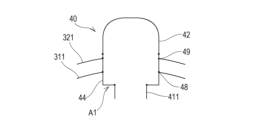
- FIG. 4 is a diagram illustrating the configuration of the assembly.
- FIG. 5 is a diagram illustrating how the connection portions are joined.
- FIG. 6 is a diagram illustrating how the connection portions are joined.
- FIG. 7 is a diagram illustrating a method for installing a pipe tower.
- FIG. 1 is a vertical cross-sectional view of a liquefied gas tank according to an embodiment of the present disclosure.
- FIG. 2 is a vertical sectional view of a liquefied gas tank according to an embodiment showing a modification of the lower part of the pipe tower.
- FIG. 3 is an enlarged vertical
- FIG. 8 is an enlarged vertical sectional view of the upper part of the liquefied gas tank according to the embodiment, showing a state in which the inner tank and the pipe tower are thermally contracted.
- FIG. 9 is a vertical cross-sectional view of a liquefied gas tank according to Modification Example 1.
- FIG. 10 is a vertical sectional view of a liquefied gas tank according to Modification 1.
- FIG. 11 is a vertical sectional view of a liquefied gas tank according to Modification Example 2.
- FIG. 12 is an enlarged vertical cross-sectional view of the upper part of the liquefied gas tank according to Modification Example 2.
- FIG. 13 is an enlarged vertical cross-sectional view of the upper part of the liquefied gas tank according to Modification Example 2, showing a state in which the inner tank and the pipe tower are thermally contracted.
- FIG. 1 is a vertical cross-sectional view of a liquefied gas tank 1 according to one embodiment of the present disclosure.
- a liquefied gas tank 1 shown in FIG. 1 is a low-temperature container that stores low-temperature liquefied gas such as liquefied hydrogen or liquefied natural gas.
- the liquefied gas tank 1 is supported by a base via a skirt.
- the base is, for example, the hull of a liquefied gas carrier.
- the liquefied gas tank 1 to which the present disclosure is applied is not limited to a cargo handling tank mounted on a ship, and may be any low-temperature container in which a pipe tower is arranged inside the tank.
- the liquefied gas tank 1 is a spherical tank.
- the liquefied gas tank 1 is not limited to a spherical tank, and may be a deformed spherical tank in the shape of an oblong ellipsoid, a stretch tank with hemispherical top and bottom and a cylindrical part in between, or a square tank in the shape of a rectangular parallelepiped.
- the liquefied gas tank 1 includes an inner tank 31 that contains liquefied gas, and an outer tank 32 that surrounds the inner tank 31.
- the wall of the inner tank 31 and the wall of the outer tank 32 are spaced apart, and a heat insulating layer 33 is provided between the inner tank 31 and the outer tank 32.
- the heat insulating layer 33 may be filled with a heat insulating material, or may be a vacuum heat insulating layer.
- a pipe tower 4 extending vertically is provided approximately at the center of the liquefied gas tank 1.
- a cargo handling pipe for loading or discharging liquefied gas into the inner tank 31, and a spray pipe through which the liquefied gas extracted from the inner tank 31 passes in order to pre-cool the inner tank 31 are arranged.
- the cargo handling pipe and the spray pipe are provided in a suspended state from the top of the pipe tower 4, and within the pipe tower 4, a cargo handling pump is provided at the lower end of the cargo handling pipe, and a spray pump is provided at the lower end of the spray pipe.
- the pipe tower 4 is also provided with a liquid level gauge, electrical wiring, and the like.
- a ladder is provided inside the pipe tower 4 so that a worker can enter the inside of the liquefied gas tank 1 from the upper part of the pipe tower 4.
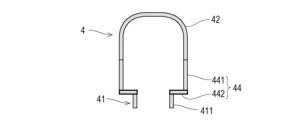
- the pipe tower 4 has a body portion 41, a head portion 42, and a connecting portion 44.
- the connecting part 44 is arranged between the body part 41 and the head part 42 in the vertical direction, and connects the body part 41 and the head part 42.
- the body portion 41 is a cylindrical body extending in the vertical direction.
- the lower end of the body 41 is joined to the bottom wall of the inner tank 31 inside the inner tank 31 .
- the outer diameter of the body portion 41 is substantially constant in the vertical direction.
- the body 41 may have a truncated cone integrally connected to the lower part of the cylinder.
- the lower end of the body part 41 is rigidly connected to the inner tank 31, and the lower part of the body part 41 does not have a deformation tolerance part that actively allows deformation. 4 can be supported well.
- the head 42 is a cylindrical body with a dome-shaped closed top.
- the head 42 is located above the outer tank 32.
- the head 42 is provided with a through hole for drawing out the pipes and wiring passed through the pipe tower 4 to the outside, a manhole for work, and the like.
- the connecting part 44 has a cylindrical shape, and the inside of the connecting part 44 communicates with the insides of the body part 41 and the head part 42.
- the connecting portion 44 may have a rectangular cylindrical shape or an elliptical cylindrical shape.
- FIG. 3 is an enlarged vertical cross-sectional view of the upper part of the liquefied gas tank 1 according to the embodiment.
- the connecting portion 44 includes a cylindrical body 441 and a lower annular plate 442.
- the cylinder 441 is a cylinder extending in the vertical direction, and the upper end of the cylinder 441 is joined to the lower end of the head 42 .
- the cylindrical body 441 and the head 42 may be continuous. Further, the cylindrical body 441 and the head 42 may be integrally configured.
- the lower end of the cylindrical body 441 is joined to the outer edge of the lower annular plate 442.
- the lower annular plate 442 is an annular flat plate having a surface substantially orthogonal to the vertical direction.
- the lower annular plate 442 may be a truncated cone (for example, a truncated cone whose inner edge is higher than its outer edge) with an inclination in a direction that cancels elastic deformation.
- the shape of the outer edge of the lower annular plate 442 is substantially the same as the outer shape of the cylindrical body 441.
- An opening is formed approximately in the center of the lower annular plate 442, and the shape of the inner edge of the opening is substantially the same as the outer shape of the body portion 41.
- the inner edge of the lower annular plate 442 is joined to the upper end of the body 41.
- the lower annular plate 442 has flexibility, and the inner edge of the lower annular plate 442 can be vertically displaced relative to the outer edge of the lower annular plate 442 by elastic deformation of the lower annular plate 442.
- the lower annular plate 442 of the connecting portion 44 is a first deformation allowing portion A1 that actively allows deformation in the vertical direction.
- the cylindrical body 441 of the connecting portion 44 has an inner tank joint 48 to which the top of the inner tank 31 is joined, and an outer tank joint 49 to which the top of the outer tank 32 is joined.
- the inner tank 31 has a top opening into which the cylinder 441 is inserted, and the inner edge of the top opening and the cylinder 441 are hermetically joined.
- the outer tank 32 has a top opening through which the cylinder 441 is inserted, and the inner edge of the top opening and the cylinder 441 are hermetically joined.
- the lower annular plate 442 of the connecting portion 44 and at least a portion of the cylindrical body 441 are located inside the inner tank 31 .
- the outer diameter D2 of the head 42 is substantially the same as or larger than the outer diameter D1 of the body 41.
- the outer diameter D4 of the connecting portion 44 (that is, the outer diameter of the cylindrical body 441) is larger than the outer diameter D1 of the body portion 41, and is the same as or larger than the outer diameter D2 of the head portion 42.
- substantially the same here refers to cases where the (outer diameters) of the two values are exactly the same, and cases where the difference between one value and the other of the two values is approximately the same as the other value. It is less than 10% and includes cases where there is a difference between the two values but the relationship between them does not change significantly even if they are considered the same.
- the outer diameter D4 of the connecting portion 44 is larger than the outer diameter D1 of the body 41, and the outer diameter D4 of the connecting portion 44 and the outer diameter D2 of the head 42 are substantially the same. [outer diameter D1 of body portion 41 ⁇ outer diameter D4 of connecting portion 44 ⁇ outer diameter D2 of head portion 42].
- FIG. 4 is a diagram illustrating the configuration of the assembly 40
- FIGS. 5 and 6 are diagrams illustrating the connection of the connecting portion 44
- FIG. 7 is a diagram illustrating a method for installing the pipe tower 4.
- Assembly 40 may be made in a factory rather than in the field.
- the cylindrical body 441 of the connecting portion 44 and the lower annular plate 442 may be fitted together by joining the upper surface of the lower annular plate 442 to the end surface of the cylindrical body 441. Furthermore, the upper portion 411 of the body 41 and the lower annular plate 442 may be connected to each other by joining the lower surface of the lower annular plate 442 to the end surface of the upper portion 411 of the body 41 .
- the cylindrical body 441 of the connecting portion 44 and the lower annular plate 442 may be joined to each other by joining the peripheral surface of the lower annular plate 442 to the inner wall of the cylindrical body 441. Furthermore, the upper portion 411 of the body 41 and the lower annular plate 442 may be connected to each other by joining an end surface of the lower annular plate 442 to the outer wall of the body 41 .
- the lower part 412 of the body 41 of the pipe tower 4 is carried into the inner tank 31, The lower end of the lower portion 412 of the body 41 and the bottom wall of the inner tank 31 are rigidly joined.
- the assembly 40 is carried in and arranged so that the upper portion 411 and the lower portion 412 of the body 41 are brought into contact with each other.
- the upper part 411 and the lower part 412 of the body 41 are joined, the main body of the inner tank 31 and the top opening periphery 311 are joined, and the main body of the outer tank 32 and the top opening periphery 321 are joined. .
- the assembly 40 includes the lower annular plate 442 which is the first deformation allowable part A1, but the load applied to the lower annular plate 442 in the state of the assembly 40 is the connecting part 44, the trunk part 41, it originates from the weight of the top opening periphery 311 of the inner tank 31 and the top opening periphery 321 of the outer tank 32. Therefore, the degree of deformation (bending) of the lower annular plate 442 due to the weight of the assembly 40 is compared with the degree of deformation of a plate provided at the bottom of the pipe tower 4 and supporting the entire load of the pipe tower 4 as in the past. And small enough.
- FIG. 8 is an enlarged vertical sectional view of the upper part of the liquefied gas tank 1 according to the embodiment, showing a state in which the inner tank 31 and the pipe tower 4 are thermally contracted.
- the inner tank 31 and the pipe tower 4 are thermally contracted. Since a temperature distribution occurs in the inner tank 31 and the pipe tower 4, the degree of thermal contraction is not uniform even if these are made of the same material.
- the pipe of the inner tank 31 is Relative displacement in the vertical direction with respect to the tower 4 is allowed, and generation of high stress at the joint between the pipe tower 4 and the inner tank 31 is avoided.
- the lower annular plate 442 is actively deformed, and as the lower annular plate 442 is deformed, the cylindrical body 441 is also deformed to some extent.
- a relative displacement occurs in the inner tank 31 and the pipe tower 4 due to a temperature difference between the inner tank 31 and the pipe tower 4 caused by the cold heat of the liquefied gas stored in the inner tank 31.
- 31 and the pipe tower 4 may also be subject to relative displacement due to the pressure or weight of the liquid. In this case as well, the relative displacement can be absorbed by the deformation of the first deformation allowing portion A1 as described above.
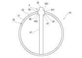
- FIG. 9 is a vertical sectional view of a liquefied gas tank 1A according to Modification 1 of the embodiment. As shown in FIG. 9, the liquefied gas tank 1A according to the first modification is different from the liquefied gas tank 1 according to the embodiment in that the outer diameter D4 of the connecting portion 44 of the pipe tower 4 is larger than the outer diameter D2 of the head 42. differ.
- the outer diameter D1 of the body 41 and the outer diameter D2 of the head 42 are substantially the same, and the outer diameter D1 of the body 41 is smaller than the outer diameter D1 of the connecting portion 44. has a large outer diameter D4 [outer diameter D1 of body portion 41 ⁇ outer diameter D2 of head portion 42 ⁇ outer diameter D4 of connecting portion 44].
- the outer diameter D4 of the connecting portion 44 is not limited by the outer diameter D2 of the head 42, and may be larger than the outer diameter D2 of the head 42. The larger the outer diameter D4 of the connecting portion 44 is, the larger the connecting portion 44 becomes and the more easily the connecting portion 44 can be deformed in the vertical direction.
- the connecting portion 44 of the pipe tower 4 of the liquefied gas tank 1A according to Modification 1 includes a cylinder 441, a lower annular plate 442, and an upper annular plate 443.
- the upper annular plate 443 is an annular flat plate having a surface substantially perpendicular to the vertical direction.
- the shape of the outer edge of the upper annular plate 443 is substantially the same as the outer shape of the cylindrical body 441.
- An opening is formed approximately in the center of the upper annular plate 443, and the shape of the inner edge of the opening is approximately the same as the outer shape of the lower end of the head 42.
- the inner edge of the upper annular plate 443 is joined to the lower end of the head 42.
- the inner tank 31 and the outer tank 32 are joined to the cylindrical body 441 of the connecting part 44, but as shown in FIG.
- the plate 443 may be formed with a curved surface that smoothly continues with the outer tank 32.
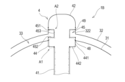
- FIG. 11 is a vertical sectional view of a liquefied gas tank 1B according to a second modification of the embodiment.
- the connection portion 44 of the pipe tower 4 also has a deformation allowable portion (second deformation allowable portion A2) between the inner tank 31 and the outer tank 32. This is different from the liquefied gas tank 1 according to the embodiment.
- FIG. 12 is an enlarged vertical cross-sectional view of the upper part of the liquefied gas tank 1B according to Modification 2.
- the cylindrical body 441 of the connection part 44 of the pipe tower 4 has at least one location between the inner tank joint part 48 and the outer tank joint part 49. It has a second deformation allowing portion A2.
- the second deformation allowing portion A2 includes an annular plate having a surface substantially perpendicular to the vertical direction. Instead of the annular plate, a truncated cone having an inclination in a direction that cancels out elastic deformation may be used.
- a truncated cone having an inclination in a direction that cancels out elastic deformation may be used.
- the cylindrical body 441 of the connecting portion 44 of the pipe tower 4 has a groove 45 continuous in the circumferential direction between the inner tank joint 48 and the outer tank joint 49.
- the groove 45 is formed by a pair of annular plates (an upper annular plate 451 and a lower annular plate 452) facing each other in the vertical direction, and a short cylindrical body 453.
- the member forming the groove 45 functions as the second deformation allowing portion A2.
- the outer diameter of the short cylinder 453 inserted between the inner tank joint 48 and the outer tank joint 49 in the cylinder 441 is smaller than the outer diameter of the cylinder 441 (that is, the outer diameter of the connecting part 44).
- the outer edge of the upper annular plate 451 is joined to the cylindrical body 441, and the inner edge of the upper annular plate 451 is joined to the upper end of the short cylindrical body 453.
- the outer edge of the lower annular plate 452 is joined to the cylinder 441, and the inner edge of the lower annular plate 452 is joined to the lower end of the lower annular plate 452.
- the outer tank 32 has a rising portion 322 rising upward from the top opening. This rising portion 322 and the connecting portion 44 are joined. The rising portion 322 may be joined to the head 42 at the connection portion between the connection portion 44 and the head 42 . In this way, a second deformation allowing portion A2 including an upper annular plate 451 and a lower annular plate 452 is provided between the joint portion of the inner tank 31 and the joint portion of the outer tank 32 in the connecting portion 44. .
- the inside of the groove 45 is a space that is continuous with the space between the inner tank 31 and the outer tank 32, and this space can be used for piping and wiring.
- the liquefied gas tank 1B when the low-temperature liquefied gas is stored in the inner tank 31, the inner tank 31 and the pipe tower 4 are thermally contracted. As shown in FIG. 13, the lower annular plate 442 of the connecting portion 44 of the pipe tower 4 is elastically deformed in the vertical direction, thereby allowing relative displacement of the inner tank 31 with respect to the pipe tower 4 in the vertical direction. High stress is prevented from being generated at the joint portion with the inner tank 31.
- the second deformation allowing portion A2 including the upper annular plate 451 and the lower annular plate 452 in the vertical direction relative displacement of the pipe tower 4 in the vertical direction with respect to the outer tank 32 is permitted, and the outer tank Relative displacement in the vertical direction of the top of the inner tank 31 with respect to the top of the pipe tower 32 is allowed, and generation of high stress at the joints between the pipe tower 4 and the inner tank 31 and the outer tank 32 is avoided.
- the upper annular plate 451 and the lower annular plate 452 are actively deformed, but as the upper annular plate 451 and the lower annular plate 452 are deformed, the short cylindrical body 453 and the cylindrical body 441 are also deformed. Somewhat deformed.
- a temperature difference occurs between the inner tank 31 and the pipe tower 4 due to the cold heat of the liquefied gas stored in the inner tank 31, and a relative displacement occurs between the inner tank 31 and the pipe tower 4, and the outer tank 32 and the pipe tower 4
- relative displacement may similarly occur when pressure or weight of liquid is applied to inner tank 31 and pipe tower 4.
- the relative displacement can be absorbed by the deformation of the first deformation permitting portion A1 and the second deformation permitting portion A2, as described above.
- the liquefied gas tank 1B according to Modification 2 is a double shell tank with an inner tank 31 and an outer tank 32
- the pipe tower 4 and the tank may be joined in the same way in a triple or more multi-shell tank.
- the junction of the inner tank 31 and the intermediate tank immediately outside the inner tank 31 are connected.
- a deformation tolerance part is provided between the joint part, and a deformation tolerance part is provided between the joint part of the intermediate tank and the joint part of the outer tank 32 in the pipe tower 4, and/or between the joint parts of the intermediate layer. provided.
- the liquefied gas tanks 1, 1A, 1B are: an inner tank 31 containing liquefied gas; an outer tank 32 surrounding an inner tank 31; A body part 41 having a lower end joined to the bottom wall in the inner tank 31, a head part 42 located above the outer tank 32, and a connecting part 44 that vertically connects the body part 41 and the head part 42. and a cylindrical pipe tower 4 extending vertically from the bottom wall of the inner tank 31 through the inner tank 31 and the outer tank 32.
- the connecting portion 44 of the pipe tower 4 includes an inner tank connecting portion 48 to which the top of the inner tank 31 is connected and an outer tank connecting portion 49 to which the top of the outer tank 32 is connected, and a cylindrical body 441 extending in the vertical direction. and a first deformation allowing portion A1 that connects the cylinder 441 and the upper end of the body 41 and allows vertical displacement of the upper end of the body 41 with respect to the cylinder 441 by elastically deforming.
- the first deformation allowing portion A1 is joined to the lower end of the cylindrical body 441. It is an annular plate (lower annular plate 442) having an outer edge and an inner edge joined to the upper end of the body portion 41.
- relative displacement in the vertical direction of the pipe tower 4 with respect to the inner tank 31 may occur.
- Such relative displacement may occur, for example, due to thermal contraction of the inner tank 31 and the pipe tower 4 when low-temperature liquefied gas is stored in the inner tank 31 of the liquefied gas tank 1.
- first deformation allowing portion A1 i.e., the lower annular plate 442 of the pipe tower 4
- relative displacement of the pipe tower 4 in the vertical direction with respect to the inner tank 31 is permitted, and the inner tank 31 and the pipe The generation of high stress at the joint with the tower 4 is avoided.
- the degree of deformation of the first deforming allowing portion A1 due to the weight of the pipe tower 4 is smaller than the conventional one.
- the degree of deformation is sufficiently small compared to the degree of deformation of the plate material provided at the bottom of the pipe tower 4 and supporting the entire load of the pipe tower 4. Therefore, in the process of installing the pipe tower 4, it is possible to omit the step of supporting the first deformation allowing portion A1 so that it does not deform.
- the upper surface of the annular plate 442 is joined to the end surface of the cylinder 441 in the liquefied gas tanks 1, 1A, 1B according to the second item,
- the lower surface of an annular plate 442 is joined to the end surface of the body portion 41.
- the peripheral surface of the annular plate 442 is joined to the inner wall of the cylinder 441 in the liquefied gas tanks 1, 1A, 1B according to the second item,
- the end face of an annular plate 442 is joined to the outer wall of the body part 41.
- the outer diameter D4 of the connecting part 44 is the outer diameter D1 of the body part 41. and substantially the same as or larger than the outer diameter D2 of the head 42.
- the outer diameter D4 of the connecting portion 44 is an arbitrary value that is not restricted by the head 42. Therefore, the difference between the outer diameter D4 of the connecting part 44 and the outer diameter D1 of the body part 41 can be designed according to the difference in the amount of deformation between the inner tank 31 and the pipe tower 4 to be absorbed.
- connection part 44 of the pipe tower 4 is connected to the inner tank joint part 48.
- a second deformation permitting portion A2 is provided between the tank joint portion 49 and elastically deformed to allow displacement of the inner tank joint portion 48 in the vertical direction with respect to the outer tank joint portion 49.
- the liquefied gas tank 1B according to the seventh item of the present disclosure is the liquefied gas tank 1B according to the sixth item, in which the second deformation allowing portion A2 is formed between the inner tank joint 48 and the outer tank joint 49 of the cylinder 441.
- the second deformation allowing portion A2 allows relative displacement in the vertical direction of the pipe tower 4 with respect to the top of the outer tank 32 joined to the outer tank joint portion 49.
- relative displacement in the vertical direction of the top of the inner tank 31 joined to the inner tank joint 48 with respect to the top of the outer tank 32 is allowed, and high stress is generated at the joints between the pipe tower 4 and the inner tank 31 and the outer tank 32. occurrence is avoided.
- the liquefied gas tank 1B according to the eighth item of the present disclosure is the liquefied gas tank 1B according to the seventh item, in which a concave groove 45 continuous in the circumferential direction in the cylinder body 441 is formed by a short cylinder body 453 and a pair of annular plates 451, 452. is formed, and the inside of the groove 45 communicates with the spaces between the inner tank 31 and the outer tank 32.
- the lower end of the body 41 of the pipe tower 4 is deformed.
- the inner tank is connected to the inner tank without using a member that allows this.
Landscapes
- Engineering & Computer Science (AREA)
- Mechanical Engineering (AREA)
- Chemical & Material Sciences (AREA)
- Combustion & Propulsion (AREA)
- Ocean & Marine Engineering (AREA)
- General Engineering & Computer Science (AREA)
- Physics & Mathematics (AREA)
- Thermal Sciences (AREA)
- Filling Or Discharging Of Gas Storage Vessels (AREA)
Priority Applications (4)
| Application Number | Priority Date | Filing Date | Title |
|---|---|---|---|
| PCT/JP2022/029318 WO2024024092A1 (ja) | 2022-07-29 | 2022-07-29 | 液化ガスタンク |
| JP2024536735A JP7792000B2 (ja) | 2022-07-29 | 2022-07-29 | 液化ガスタンク |
| CN202280097684.4A CN119486934A (zh) | 2022-07-29 | 2022-07-29 | 液化气罐 |
| KR1020257004563A KR20250036224A (ko) | 2022-07-29 | 2022-07-29 | 액화 가스 탱크 |
Applications Claiming Priority (1)
| Application Number | Priority Date | Filing Date | Title |
|---|---|---|---|
| PCT/JP2022/029318 WO2024024092A1 (ja) | 2022-07-29 | 2022-07-29 | 液化ガスタンク |
Publications (1)
| Publication Number | Publication Date |
|---|---|
| WO2024024092A1 true WO2024024092A1 (ja) | 2024-02-01 |
Family
ID=89705853
Family Applications (1)
| Application Number | Title | Priority Date | Filing Date |
|---|---|---|---|
| PCT/JP2022/029318 Ceased WO2024024092A1 (ja) | 2022-07-29 | 2022-07-29 | 液化ガスタンク |
Country Status (4)
| Country | Link |
|---|---|
| JP (1) | JP7792000B2 (https=) |
| KR (1) | KR20250036224A (https=) |
| CN (1) | CN119486934A (https=) |
| WO (1) | WO2024024092A1 (https=) |
Citations (3)
| Publication number | Priority date | Publication date | Assignee | Title |
|---|---|---|---|---|
| JPH0429200Y2 (https=) * | 1986-07-31 | 1992-07-15 | ||
| JP2014163412A (ja) * | 2013-02-22 | 2014-09-08 | Mitsubishi Heavy Ind Ltd | Lng貯蔵装置、及び船舶 |
| JP2022061153A (ja) * | 2020-10-06 | 2022-04-18 | 三菱造船株式会社 | タンク、船舶 |
-
2022
- 2022-07-29 CN CN202280097684.4A patent/CN119486934A/zh active Pending
- 2022-07-29 JP JP2024536735A patent/JP7792000B2/ja active Active
- 2022-07-29 KR KR1020257004563A patent/KR20250036224A/ko active Pending
- 2022-07-29 WO PCT/JP2022/029318 patent/WO2024024092A1/ja not_active Ceased
Patent Citations (3)
| Publication number | Priority date | Publication date | Assignee | Title |
|---|---|---|---|---|
| JPH0429200Y2 (https=) * | 1986-07-31 | 1992-07-15 | ||
| JP2014163412A (ja) * | 2013-02-22 | 2014-09-08 | Mitsubishi Heavy Ind Ltd | Lng貯蔵装置、及び船舶 |
| JP2022061153A (ja) * | 2020-10-06 | 2022-04-18 | 三菱造船株式会社 | タンク、船舶 |
Non-Patent Citations (2)
| Title |
|---|
| ASAI KOETSU: "Design and Strength Estimation of New-Type Cylindrical Tank for Liquefied Gas by Koetsu Asai, Member Hajime Kawano, Member", JOURNAL OF THE SOCIETY OF NAVAL ARCHITECTS OF JAPAN, vol. 1991, no. 170, 1 January 1991 (1991-01-01), pages 565 - 575, XP093135169 * |
| LEE, DONG-HUN; MOON, KIHO; NAM, KIIL; KIM, SUNGYOON; CHANG, DAEJUN: "Comparison of Moss and Membrane Type LNG Carriers in Cooldown Procedure", THEORIES AND APPLICATION OF CHEMICAL ENGINEERING, vol. 9, no. 2, 1 January 2003 (2003-01-01), KOREA , pages 1748 - 1751, XP009552769, ISSN: 1225-9004 * |
Also Published As
| Publication number | Publication date |
|---|---|
| JP7792000B2 (ja) | 2025-12-24 |
| KR20250036224A (ko) | 2025-03-13 |
| CN119486934A (zh) | 2025-02-18 |
| JPWO2024024092A1 (https=) | 2024-02-01 |
Similar Documents
| Publication | Publication Date | Title |
|---|---|---|
| KR101505798B1 (ko) | 베이스플레이트 및 이를 포함하는 화물창 | |
| RU2535357C1 (ru) | Конструкция фланцевого участка купола резервуара | |
| US11056264B2 (en) | Rupture resistant system | |
| JP2007525624A (ja) | 液化天然ガスの保存タンク及びその製造方法 | |
| RU2307973C2 (ru) | Резервуар для хранения криогенной текучей среды и способ изготовления герметичного резервуара | |
| WO2022145296A1 (ja) | 三重殻タンク | |
| KR100649316B1 (ko) | 액화천연가스 저장탱크의 앵커 구조체 | |
| JP2013238285A (ja) | 液体貯蔵タンク | |
| WO2024024092A1 (ja) | 液化ガスタンク | |
| CN116324264A (zh) | 具有集成的或可操作地连接的支撑系统的隔绝罐 | |
| EP3760910B1 (en) | Double-shell tank and liquefied gas carrier ship | |
| CN116857553B (zh) | 一种深冷复合管路及其应用 | |
| CN218268525U (zh) | 一种液氢储罐 | |
| JP7498848B2 (ja) | 三重殻タンク | |
| KR101291126B1 (ko) | 액화천연가스 저장탱크의 펌프타워 단열구조 | |
| AU2020331403A1 (en) | Pipe leadthrough module for a cryogenic container | |
| WO2021260946A1 (ja) | 二重殻タンク | |
| JP2024004406A (ja) | 多重殻タンク | |
| JP7723493B2 (ja) | 二重殻タンク及び船舶 | |
| CN121953231A (zh) | 一种泵塔及流体储罐 | |
| KR100765933B1 (ko) | Lng 저장탱크 내에 밀봉벽 및 단열벽을 지지하기 위한지지 구조체 | |
| KR20250149211A (ko) | 액화가스 저장탱크의 펌프타워 베이스 서포트 구조체 | |
| KR20230157568A (ko) | 차량용 초저온 용기 및 차량용 초저온 용기의 외부 용기 제조방법 | |
| WO2024062623A1 (ja) | 多重殻タンク | |
| JPH10220697A (ja) | 低温タンクの内槽用アンカー構造 |
Legal Events
| Date | Code | Title | Description |
|---|---|---|---|
| 121 | Ep: the epo has been informed by wipo that ep was designated in this application |
Ref document number: 22953180 Country of ref document: EP Kind code of ref document: A1 |
|
| ENP | Entry into the national phase |
Ref document number: 2024536735 Country of ref document: JP Kind code of ref document: A |
|
| WWE | Wipo information: entry into national phase |
Ref document number: 202280097684.4 Country of ref document: CN |
|
| ENP | Entry into the national phase |
Ref document number: 20257004563 Country of ref document: KR Kind code of ref document: A |
|
| WWE | Wipo information: entry into national phase |
Ref document number: 1020257004563 Country of ref document: KR |
|
| WWP | Wipo information: published in national office |
Ref document number: 202280097684.4 Country of ref document: CN |
|
| NENP | Non-entry into the national phase |
Ref country code: DE |
|
| WWP | Wipo information: published in national office |
Ref document number: 1020257004563 Country of ref document: KR |
|
| 122 | Ep: pct application non-entry in european phase |
Ref document number: 22953180 Country of ref document: EP Kind code of ref document: A1 |