WO2024024039A1 - Blood storage container and blood collection instrument - Google Patents
Blood storage container and blood collection instrument Download PDFInfo
- Publication number
- WO2024024039A1 WO2024024039A1 PCT/JP2022/029137 JP2022029137W WO2024024039A1 WO 2024024039 A1 WO2024024039 A1 WO 2024024039A1 JP 2022029137 W JP2022029137 W JP 2022029137W WO 2024024039 A1 WO2024024039 A1 WO 2024024039A1
- Authority
- WO
- WIPO (PCT)
- Prior art keywords
- blood
- storage container
- axial direction
- blood collection
- container
- Prior art date
Links
- 239000008280 blood Substances 0.000 title claims abstract description 304
- 210000004369 blood Anatomy 0.000 title claims abstract description 303
- 238000003860 storage Methods 0.000 title claims abstract description 173
- 238000000926 separation method Methods 0.000 claims abstract description 62
- 238000010241 blood sampling Methods 0.000 claims description 126
- 230000002093 peripheral effect Effects 0.000 claims description 17
- 238000003825 pressing Methods 0.000 claims description 6
- 230000017531 blood circulation Effects 0.000 claims description 4
- 230000007423 decrease Effects 0.000 claims description 4
- 238000007599 discharging Methods 0.000 claims description 2
- 238000001125 extrusion Methods 0.000 claims 1
- 238000004321 preservation Methods 0.000 abstract 2
- 210000002381 plasma Anatomy 0.000 description 74
- 239000000523 sample Substances 0.000 description 65
- 238000012360 testing method Methods 0.000 description 61
- 210000000601 blood cell Anatomy 0.000 description 59
- 238000005119 centrifugation Methods 0.000 description 25
- 238000010790 dilution Methods 0.000 description 24
- 239000012895 dilution Substances 0.000 description 24
- 239000007788 liquid Substances 0.000 description 17
- 238000000034 method Methods 0.000 description 17
- 239000000243 solution Substances 0.000 description 14
- 239000000654 additive Substances 0.000 description 13
- 239000003795 chemical substances by application Substances 0.000 description 13
- 238000004458 analytical method Methods 0.000 description 12
- 239000003550 marker Substances 0.000 description 12
- 239000004033 plastic Substances 0.000 description 12
- 229920003023 plastic Polymers 0.000 description 12
- 230000000996 additive effect Effects 0.000 description 11
- 238000009534 blood test Methods 0.000 description 10
- 239000003085 diluting agent Substances 0.000 description 10
- 238000005259 measurement Methods 0.000 description 10
- 230000009471 action Effects 0.000 description 9
- 210000004180 plasmocyte Anatomy 0.000 description 9
- 238000002156 mixing Methods 0.000 description 6
- 210000002966 serum Anatomy 0.000 description 6
- 238000007689 inspection Methods 0.000 description 5
- 210000005259 peripheral blood Anatomy 0.000 description 5
- 239000011886 peripheral blood Substances 0.000 description 5
- 239000000126 substance Substances 0.000 description 5
- 238000002835 absorbance Methods 0.000 description 4
- 239000007864 aqueous solution Substances 0.000 description 4
- 210000001808 exosome Anatomy 0.000 description 4
- 239000012528 membrane Substances 0.000 description 4
- 239000000203 mixture Substances 0.000 description 4
- PUZPDOWCWNUUKD-UHFFFAOYSA-M sodium fluoride Chemical compound [F-].[Na+] PUZPDOWCWNUUKD-UHFFFAOYSA-M 0.000 description 4
- XLYOFNOQVPJJNP-UHFFFAOYSA-N water Substances O XLYOFNOQVPJJNP-UHFFFAOYSA-N 0.000 description 4
- 206010018910 Haemolysis Diseases 0.000 description 3
- 238000011481 absorbance measurement Methods 0.000 description 3
- 239000003146 anticoagulant agent Substances 0.000 description 3
- 229940127219 anticoagulant drug Drugs 0.000 description 3
- 238000011088 calibration curve Methods 0.000 description 3
- 201000010099 disease Diseases 0.000 description 3
- 208000037265 diseases, disorders, signs and symptoms Diseases 0.000 description 3
- 230000007613 environmental effect Effects 0.000 description 3
- 238000005534 hematocrit Methods 0.000 description 3
- 230000008588 hemolysis Effects 0.000 description 3
- 238000004519 manufacturing process Methods 0.000 description 3
- KCXVZYZYPLLWCC-UHFFFAOYSA-N EDTA Chemical compound OC(=O)CN(CC(O)=O)CCN(CC(O)=O)CC(O)=O KCXVZYZYPLLWCC-UHFFFAOYSA-N 0.000 description 2
- 239000006173 Good's buffer Substances 0.000 description 2
- HTTJABKRGRZYRN-UHFFFAOYSA-N Heparin Chemical compound OC1C(NC(=O)C)C(O)OC(COS(O)(=O)=O)C1OC1C(OS(O)(=O)=O)C(O)C(OC2C(C(OS(O)(=O)=O)C(OC3C(C(O)C(O)C(O3)C(O)=O)OS(O)(=O)=O)C(CO)O2)NS(O)(=O)=O)C(C(O)=O)O1 HTTJABKRGRZYRN-UHFFFAOYSA-N 0.000 description 2
- 230000000740 bleeding effect Effects 0.000 description 2
- 210000001124 body fluid Anatomy 0.000 description 2
- 239000010839 body fluid Substances 0.000 description 2
- 239000007853 buffer solution Substances 0.000 description 2
- 210000004027 cell Anatomy 0.000 description 2
- 238000005520 cutting process Methods 0.000 description 2
- 239000012470 diluted sample Substances 0.000 description 2
- 238000007865 diluting Methods 0.000 description 2
- 238000005516 engineering process Methods 0.000 description 2
- 230000005484 gravity Effects 0.000 description 2
- 229960002897 heparin Drugs 0.000 description 2
- 229920000669 heparin Polymers 0.000 description 2
- 230000002209 hydrophobic effect Effects 0.000 description 2
- 239000000463 material Substances 0.000 description 2
- 230000007246 mechanism Effects 0.000 description 2
- 239000008363 phosphate buffer Substances 0.000 description 2
- 239000002504 physiological saline solution Substances 0.000 description 2
- 238000012123 point-of-care testing Methods 0.000 description 2
- 230000009467 reduction Effects 0.000 description 2
- 239000001509 sodium citrate Substances 0.000 description 2
- NLJMYIDDQXHKNR-UHFFFAOYSA-K sodium citrate Chemical compound O.O.[Na+].[Na+].[Na+].[O-]C(=O)CC(O)(CC([O-])=O)C([O-])=O NLJMYIDDQXHKNR-UHFFFAOYSA-K 0.000 description 2
- 239000011775 sodium fluoride Substances 0.000 description 2
- 235000013024 sodium fluoride Nutrition 0.000 description 2
- 210000002105 tongue Anatomy 0.000 description 2
- 210000003462 vein Anatomy 0.000 description 2
- 239000001763 2-hydroxyethyl(trimethyl)azanium Substances 0.000 description 1
- 208000034048 Asymptomatic disease Diseases 0.000 description 1
- 235000019743 Choline chloride Nutrition 0.000 description 1
- WQZGKKKJIJFFOK-GASJEMHNSA-N Glucose Natural products OC[C@H]1OC(O)[C@H](O)[C@@H](O)[C@@H]1O WQZGKKKJIJFFOK-GASJEMHNSA-N 0.000 description 1
- 102000001554 Hemoglobins Human genes 0.000 description 1
- 108010054147 Hemoglobins Proteins 0.000 description 1
- 241001465754 Metazoa Species 0.000 description 1
- 108700011259 MicroRNAs Proteins 0.000 description 1
- 241000699670 Mus sp. Species 0.000 description 1
- 206010028980 Neoplasm Diseases 0.000 description 1
- PNNCWTXUWKENPE-UHFFFAOYSA-N [N].NC(N)=O Chemical compound [N].NC(N)=O PNNCWTXUWKENPE-UHFFFAOYSA-N 0.000 description 1
- 230000001133 acceleration Effects 0.000 description 1
- XECAHXYUAAWDEL-UHFFFAOYSA-N acrylonitrile butadiene styrene Chemical compound C=CC=C.C=CC#N.C=CC1=CC=CC=C1 XECAHXYUAAWDEL-UHFFFAOYSA-N 0.000 description 1
- 229920000122 acrylonitrile butadiene styrene Polymers 0.000 description 1
- 239000004676 acrylonitrile butadiene styrene Substances 0.000 description 1
- 230000008901 benefit Effects 0.000 description 1
- WQZGKKKJIJFFOK-VFUOTHLCSA-N beta-D-glucose Chemical compound OC[C@H]1O[C@@H](O)[C@H](O)[C@@H](O)[C@@H]1O WQZGKKKJIJFFOK-VFUOTHLCSA-N 0.000 description 1
- 238000012742 biochemical analysis Methods 0.000 description 1
- 210000001772 blood platelet Anatomy 0.000 description 1
- 210000004204 blood vessel Anatomy 0.000 description 1
- 238000004364 calculation method Methods 0.000 description 1
- 201000011510 cancer Diseases 0.000 description 1
- 230000008859 change Effects 0.000 description 1
- 229960003178 choline chloride Drugs 0.000 description 1
- SGMZJAMFUVOLNK-UHFFFAOYSA-M choline chloride Chemical compound [Cl-].C[N+](C)(C)CCO SGMZJAMFUVOLNK-UHFFFAOYSA-M 0.000 description 1
- 239000011248 coating agent Substances 0.000 description 1
- 238000000576 coating method Methods 0.000 description 1
- 150000001875 compounds Chemical class 0.000 description 1
- 238000011109 contamination Methods 0.000 description 1
- 238000013461 design Methods 0.000 description 1
- 210000003743 erythrocyte Anatomy 0.000 description 1
- 238000001704 evaporation Methods 0.000 description 1
- 230000008020 evaporation Effects 0.000 description 1
- 238000002474 experimental method Methods 0.000 description 1
- 238000001914 filtration Methods 0.000 description 1
- -1 for example Substances 0.000 description 1
- 239000011521 glass Substances 0.000 description 1
- 239000008103 glucose Substances 0.000 description 1
- 230000036541 health Effects 0.000 description 1
- 230000005661 hydrophobic surface Effects 0.000 description 1
- 230000006872 improvement Effects 0.000 description 1
- 210000000265 leukocyte Anatomy 0.000 description 1
- 238000011528 liquid biopsy Methods 0.000 description 1
- 238000000691 measurement method Methods 0.000 description 1
- 108020004999 messenger RNA Proteins 0.000 description 1
- 239000011259 mixed solution Substances 0.000 description 1
- 238000012986 modification Methods 0.000 description 1
- 230000004048 modification Effects 0.000 description 1
- 230000035772 mutation Effects 0.000 description 1
- 238000011017 operating method Methods 0.000 description 1
- 239000004417 polycarbonate Substances 0.000 description 1
- 229920000515 polycarbonate Polymers 0.000 description 1
- 229920000642 polymer Polymers 0.000 description 1
- 102000004169 proteins and genes Human genes 0.000 description 1
- 108090000623 proteins and genes Proteins 0.000 description 1
- 238000000275 quality assurance Methods 0.000 description 1
- 239000005871 repellent Substances 0.000 description 1
- 238000010079 rubber tapping Methods 0.000 description 1
- 238000005070 sampling Methods 0.000 description 1
- 238000012216 screening Methods 0.000 description 1
- 238000007789 sealing Methods 0.000 description 1
- 230000035945 sensitivity Effects 0.000 description 1
- 238000009751 slip forming Methods 0.000 description 1
- 238000010561 standard procedure Methods 0.000 description 1
- 238000012546 transfer Methods 0.000 description 1
- 239000002699 waste material Substances 0.000 description 1
- 238000005303 weighing Methods 0.000 description 1
Images


Classifications
-
- A—HUMAN NECESSITIES
- A61—MEDICAL OR VETERINARY SCIENCE; HYGIENE
- A61J—CONTAINERS SPECIALLY ADAPTED FOR MEDICAL OR PHARMACEUTICAL PURPOSES; DEVICES OR METHODS SPECIALLY ADAPTED FOR BRINGING PHARMACEUTICAL PRODUCTS INTO PARTICULAR PHYSICAL OR ADMINISTERING FORMS; DEVICES FOR ADMINISTERING FOOD OR MEDICINES ORALLY; BABY COMFORTERS; DEVICES FOR RECEIVING SPITTLE
- A61J1/00—Containers specially adapted for medical or pharmaceutical purposes
- A61J1/05—Containers specially adapted for medical or pharmaceutical purposes for collecting, storing or administering blood, plasma or medical fluids ; Infusion or perfusion containers
-
- G—PHYSICS
- G01—MEASURING; TESTING
- G01N—INVESTIGATING OR ANALYSING MATERIALS BY DETERMINING THEIR CHEMICAL OR PHYSICAL PROPERTIES
- G01N1/00—Sampling; Preparing specimens for investigation
- G01N1/02—Devices for withdrawing samples
- G01N1/10—Devices for withdrawing samples in the liquid or fluent state
Definitions
- the present invention relates to a blood sampling device and a blood storage container used for collecting minute amounts of blood and preparing, storing, and analyzing blood samples.
- Blood tests and other tests that analyze human body fluids as samples are performed to closely examine the manifestation of diseases and examine the state of health of the body.
- blood collection is known as venous blood collection, such as syringe collection by puncturing a brachial vein. Venous blood sampling may be difficult for infants, small blood vessels, or fragile patients. In such cases, it is known to collect peripheral blood from a fingertip or the like as a test sample.
- Test samples required for blood tests in various fields such as chemistry, immunology, and hematology generally require a volume of several microliters to several tens of microliters per test item.
- techniques have been widely disclosed that allow a trace amount of blood to be collected and analyzed with high sensitivity.
- a method in which a predetermined amount of blood is aspirated from a small amount of blood bled by pricking a fingertip with a lancet using a blood sampling tool or the like.
- This method of collecting peripheral blood samples is minimally invasive, reduces the risk of contamination with body blood and hemolysis due to insufficient blood sampling capacity or pressure during bleeding, and collects as small a volume as possible that is necessary and sufficient for testing. It is advisable to take blood.
- blood cells red blood cells, white blood cells, platelets
- centrifugation techniques are widely used as a standard method for separating blood cells and plasma (serum).
- venous blood collection it is known that 1 ml or more of blood is collected using a syringe, and the blood cells and plasma are centrifuged using a separating agent sealed in a test tube in advance.
- a separating agent sealed in a test tube in advance.
- the amount of plasma that can be aspirated on average is about 15 ⁇ l, and the plasma yield is about 25% even though the volume ratio of the plasma sample to the total blood volume is 55%. Therefore, when performing a minute blood test from a fingertip or the like, it is common to collect approximately four times the amount of sample of plasma or the like required for the test.
- a membrane separation method is sometimes used that uses multiple permeable membranes to separate plasma from a small amount of blood sample, rather than centrifugation.
- the blood collection device used in this method sucks the blood collected at the punctured fingertip into a filter containing an anticoagulant, and then drops the filter into a buffer solution and shakes it.
- a test sample is prepared by filtering the mixed solution of blood and buffer solution through a membrane to separate blood cells and plasma.
- the test sample prepared by this method is a plasma sample obtained by diluting whole blood in a non-quantitative manner and separating it by membrane permeation. Spilling of blood cell solution into the diluent may occur.
- a device called a capillary which utilizes capillary action, is generally used to collect blood collected from a fingertip or the like.
- Blood stored in a fingertip or the like is subjected to a force that tries to shrink the liquid level due to surface tension, and as a result, the liquid level is pushed up. Since the force pushing up the liquid level is equal to the vertical component of the surface tension near the wall surface, a capillary phenomenon occurs that pushes up the liquid level inside the capillary until this force and the weight of the sucked up liquid balance out.
- the tip is brought into contact with the surface of blood cells, and an appropriate amount of minute blood is collected using capillary action.
- Capillaries are generally straight glass tubes with a length of about 10 mm, an inner diameter of 1 mm or less, and a thickness of about 0.2 mm, and are used by third parties such as doctors and nurses to collect blood from a few microliters to several tens of microliters. It is often done.
- a method is sometimes used in which blood collected at a fingertip or the like is directly poured into a storage container with a tongue. This method is generally performed by a skilled third party, such as a doctor or nurse, because the blood that has been sufficiently collected in the fingertip must be stored in a storage container without flowing or falling.
- Blood sampling devices for self-collecting small amounts of blood from a fingertip or other source without relying on a third party are generally not capillaries or containers with tongues, but are often dedicated blood sampling devices designed for self-collection.
- a plastic tube having a capillary suction section with a tip diameter of approximately 0.5 mm to 1.0 mm and a tapered conical outlet structure connected to the capillary suction section may be used.
- the tip of a blood sampling device is brought into contact with the blood collected at the fingertip after puncturing it with a lancet or the like from diagonally below, and the blood is suctioned by capillary action and flows into the container under the pressure of its own weight.
- the wall surface of plastic has hydrophobic properties, it becomes water-repellent when the tip comes into contact with blood, and capillary suction force cannot be exerted as it is. Therefore, when a plastic tube is generally used as a blood sampling device that utilizes capillarity, countermeasures are taken to ensure contact suction, such as making the inner wall surface hydrophilic.
- Patent Documents 1 and 2 have already been proposed as techniques related to this type of general blood collection.
- a method often used is to puncture the fingertip with a lancet and aspirate the small amount of blood collected at the puncture site with a plastic blood collection tip.
- the amount of blood necessary for the test usually several tens of microliters to 100 microliters, flows into the hemolysis device by creating an inclined shape like a pipette tip from the capillary tip.
- a suction tool is used to draw blood into the hemolysis tool. It is necessary to have an inflow.
- the separated plasma portion is diluted with a diluent and the diluted plasma solution is used as a sample, and the blood cell portion is hemolyzed to measure the components. do.
- a fixed amount of plasma is dispensed, and the liquid is diluted with a fixed amount of diluent to create a constant dilution plasma solution. If a constant dilution plasma solution is measured as a test sample, the reported value shall be the actual measured value multiplied by the dilution rate. In this dilution operation, accurate dispensing of a predetermined amount is essential to maintain inspection accuracy.
- the plasma part and the blood cell part are not physically separated and there is a direct contact separation surface between the blood cells and plasma, for example, when 30 ⁇ l of blood is centrifuged in a 3 mm diameter container, The upper plasma volume is only 2 mm deep, making it difficult to dispense accurately and in a sufficient amount.
- a blood sample is left without physically separating the blood cells and plasma (serum) after collection or centrifugation, components in the blood cells, such as glucose and urea nitrogen, will spill out into the plasma (serum) portion and affect the analysis results. influence Therefore, when it takes a certain amount of time to carry out a test, such as when transporting a specimen after blood collection, it is necessary to physically separate plasma and blood cells. For this separation, a centrifugal separation technique using a separating agent is generally used.
- the amount of blood required for analysis varies depending on the test items and their combinations.
- various tests can be performed by generally collecting a quantitative amount of blood of 1 ml or more, but on the other hand, much of the collected blood becomes surplus and is discarded.
- micro blood tests in order to reduce the invasiveness of the user and make the most of the limited amount of blood collected, we set a sample concentration range for each item that allows for highly sensitive measurements. Dilute the sample within the chamber, secure the amount of sample necessary for the test, and perform the measurement.
- the blood collection amount and dilution rate (diluted sample amount) are set fixedly. For this reason, inspection items and item combinations have to be fixed, making it difficult to set items flexibly according to the inspection purpose.
- the present invention has been developed to quickly and easily collect a small amount of blood stored at a fingertip, etc. according to the required amount of blood that changes depending on the test purpose, and add the blood in the same container.
- the purpose of the present invention is to provide a blood storage container and a blood sampling device to reduce the burden and stably and efficiently perform tests related to blood item analysis.
- One aspect of the present invention is a blood storage container that stores and preserves collected blood, and includes a storage container configured in a hollow shape and an airtight container attached to an end of the storage container.
- the container is continuous with a blood collection space in which a first opening connected to a blood collection chip is formed on one axial side, and the other end of the blood collection space in the axial direction, and has a smaller cross section than the blood collection space.
- the airtight container has a lid portion movably placed along the axial direction so as to cover the second opening on the other axial side of the storage space of the storage container, and a lid portion on the inside of the lid portion.
- the blood storage container has a closed container shaft that is formed to protrude and is movable in the axial direction while in contact with the inner surface of the storage space.
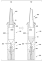
- FIG. 1 is a longitudinal sectional view showing an assembled state of a blood sampling device according to an embodiment of the present invention.
- FIG. 2 is an exploded perspective cross-sectional view showing the configuration of a blood sampling device.
- FIG. 2 is a cross-sectional view showing the configuration of a container lid that closes the containment container.
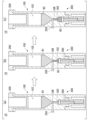
- FIG. 3 is a cross-sectional view showing how the blood sampling device is used.
- FIG. 2 is a cross-sectional view showing a blood sampling method using a blood sampling device.
- FIG. 3 is a cross-sectional view showing how to use the blood sampling device.
- FIG. 2 is a cross-sectional view showing a centrifugation method using a blood storage container.
- FIG. 3 is a cross-sectional view showing a method of dispensing blood cells from a blood storage container.
- FIG. 3 is a cross-sectional view showing a method of measuring plasma in a blood storage container.
- FIG. 3 is a cross-sectional view showing a method for discharging blood from a blood sampling device.
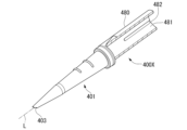
- FIG. 7 is an exploded perspective view showing the configuration of a blood sampling device according to a modified example.
- FIG. 7 is a perspective cross-sectional view showing the configuration of a blood sampling chip according to a modified example.
- XYZ axes are set orthogonal to each other, the Z-axis direction is referred to as the axial direction, the +Z side of the Z-axis is referred to as one axial side, the -Z side is referred to as the other axial side, etc.
- the blood sampling device 1 includes a blood sampling chip 400 for collecting blood, and a blood storage container 10 to which the blood sampling chip 400 is attached.
- the blood storage container 10 is formed to store and preserve blood collected by the blood collection chip 400.
- the blood storage container 10 includes a storage container 100 in which a blood collection space 102 for storing blood is formed, a closed container 300 in which a storage space 302 for storing blood is formed, and a dial part 350 provided in the closed container 300. Equipped with.
- the blood storage container 10 is sealed with a container lid 200, which will be described later, in place of the blood collection chip 400.
- the storage container 100, the sealed container 300, and the blood collection chip 400 are preferably made of a transparent, hard polymer compound material such as polycarbonate or acrylonitrile butadiene styrene, so that blood collection, blood separation, and blood storage can be monitored from the outside. Can be easily recognized visually.
- the containment vessel 100 and the closed vessel 300 communicate with each other through a narrow separation channel 10R having a predetermined length.
- a small amount of blood is sealed in the storage container 100.
- the blood storage container 10 is centrifuged as described below, and upon completion of centrifugation, the plasma portion is stored in the storage container 100 and the blood cell portion is stored in a sealed container 300 in a physically separated state.
- the blood storage container 10 is provided with a stopper 250, which is a mechanism for sealing the separation channel 10R after centrifugation.
- the stopper 250 seals the separation channel 10R based on a pushing operation.
- the stopper 250 closes the separation channel 10R and maintains a physically separated state in which the plasma part stored in the storage container 100 and the blood cell part stored in the closed container 300 do not mix again.
- the storage container 100 is, for example, formed in a cylindrical shape.
- a blood collection space 102 is formed inside the storage container 100 to store a small amount of blood.
- the cross-sectional shape (cross section) of the blood collection space 102 perpendicular to the axial direction is circular.
- a circular first opening 101 is formed at one end of the blood collection space 102 in the axial direction.
- a blood sampling chip 400 which will be described later, is connected to the first opening 101.
- a radially protruding flange portion 101F is formed on the outer circumferential surface of one end of the blood collection space 102 in the axial direction.
- the blood collection chip 400 is removed and a container lid 200 (see FIG. 3), which will be described later, is attached to the first opening 101.
- the blood collection space 102 is sealed by the container lid 200.
- the blood storage container 10 can perform all testing operations from blood collection to sample transportation, centrifugation, and sample measurement without dispensing the sample.
- a first tapered portion 103 whose cross-sectional area decreases toward the end is formed on the other side in the axial direction of the blood collection space 102 .
- the first tapered portion 103 is formed as a solution reservoir.
- the other end of the first tapered portion 103 in the axial direction is continuous with a separation flow path 10R, which will be described later. That is, the blood collection space 102 is formed so as to be continuous with the separation channel 10R on the other side in the axial direction.
- a closed container 300 is provided on the other axial side of the containment container 100 .
- the blood stored in the storage container 100 is stored in the closed container 300.
- the closed container 300 is formed into a cylindrical shape.
- a storage space 302 for storing blood is formed inside the closed container 300.
- the cross-sectional shape (cross section) of the storage space 302 perpendicular to the axial direction is circular.
- a second tapered portion 303 whose cross-sectional area increases toward the storage space 302 is formed on one side of the storage space 302 in the axial direction.
- One axial end of the second tapered portion 303 is continuous with the separation channel 10R.
- the storage space 302 is continuous with the blood collection space 102 via the separation channel 10R.
- the separation channel 10R is formed so that the blood collection space 102 and the storage space 302 are continuous.
- the cross section of the separation channel 10R is smaller than the cross section of the blood collection space 102.
- the cross section of the separation channel 10R is formed smaller than the cross section of the storage space 302. That is, the cross section of the storage space 302 is formed larger than the cross section of the separation channel 10R.
- the storage space 302 is formed in a cylindrical shape.
- a circular second opening 301 is formed at the other end of the storage space 302 in the axial direction.
- a protrusion 304 having a second opening 301 and protruding toward the other axial side is formed at the other end of the closed container 300 in the axial direction.
- the outer circumferential surface 305 of the protrusion 304 is formed to bulge in the radial direction.
- a dial portion 350 is rotatably fitted into the protrusion 304 .
- the dial portion 350 includes a plunger 360 that protrudes along the axis L direction.
- a fitting portion 351 that fits into the protrusion 304 is provided at one end of the dial portion 350 in the axial direction.
- An inner circumferential surface 352 of the fitting portion 351 is formed to be concave in the radial direction.
- the inner circumferential surface 352 of the fitting portion 351 fits into the outer circumferential surface 305 of the protruding portion 304 .
- the dial part 350 is rotatably provided on the other axial side of the closed container 300.
- Two slits 354 are formed in the dial portion 350 symmetrically with respect to the axis L so as to cut out the outer circumferential surface and the inner circumferential surface along the axis L direction.
- the slit width of the slit 354 is reduced by pressing the outer peripheral surface.
- the fitting portion 351 deforms to expand in the radial direction as the slit width decreases, and the fitting between the inner circumferential surface 352 and the outer circumferential surface 305 of the protruding portion 304 is released.
- the dial portion 350 is removed from the closed container 300 together with the plunger 360 when the fitting portion 351 and the outer circumferential surface 305 of the protruding portion 304 are disengaged. That is, when the outer peripheral surface of the dial portion 350 is strongly pressed from both lateral directions, the width of the slit 354 is reduced, the fitting portion 351 is widened, and the dial portion 350 is removed from the protruding portion 304. Since the plunger 360 is also removed from the closed container 300 together with the dial portion 350, the plunger 360 can be pulled out from the storage space 302.
- a through hole 353 is formed in the dial portion 350 along the axis L direction.
- a thread groove 353M is formed in the through hole 353.
- a threaded portion 361 formed on the plunger 360 is screwed into the through hole 353 .
- the plunger 360 is provided inside the dial portion 350 so as to protrude along the axial direction.
- a head 362 having a circular cross section is formed at one end of the plunger 360 in the axial direction.
- the outer diameter of the head 362 is slightly smaller than the inner diameter of the storage space 302.
- the head 362 is formed into a piston shape.
- the head 362 is configured to be able to slide along the axis L while being in close contact with the inner surface of the storage space 302 .
- the head 362 is inserted into the storage space 302 from the second opening 301.
- the dial part 350 is rotated around the axis L
- the screw part 361 rotates with respect to the through hole 353, and the plunger 360 moves along the axis with the head 362 in close contact with the inner surface of the storage space 302. It becomes movable along the L direction.
- the storage container 100 and the sealed container 300 are formed with a perfect circular cross section in consideration of the ease of the manufacturing process and the rotation of the threaded portion 361 and the threaded groove 353M, as well as the rotation of the plunger 360 due to the rotation. be done.
- the containment vessel 100 and the closed vessel 300 may be formed in a cross-sectional shape other than a perfect circle at a portion that does not involve relative rotation.
- the containment vessel 100 and the sealed container 300 may have, for example, a polygonal or non-circular cross-sectional shape on the outer circumferential surface for the purpose of improving handling properties, or may have irregularities formed on the outer circumferential surface as appropriate. Good too.
- through holes 10S are continuously formed in a direction perpendicular to the axis L.
- a stopper 250 is fitted into the through hole 10S.
- the stopper 250 includes a pressing portion 251 for performing a pushing operation, and a sliding portion 252 inserted into the through hole 10S.
- the sliding part 252 moves along the through hole 10S, closes the separation flow path 10R, and blocks the blood collection space 102 and the storage space 302.
- the sliding part 252 moves along the through hole 10S and opens the separation channel 10R. Thereby, the blood collection space 102 and the storage space 302 communicate with each other.
- the stopper 250 is provided in the separation flow path 10R so as to be movable in a direction intersecting the axis L direction, and is provided so as to communicate with or shield the blood collection space 102 and the storage space 302.
- the separation channel 10R is closed.
- By closing the separation channel 10R using the stopper 250 it is possible to maintain a physically separated state in which the plasma part stored in the storage container 100 and the blood cell part stored in the closed container 300 do not mix again. can.
- the blood collection chip 400 is detachably attached to one axial side of the storage container 100 so as to close the first opening 101.
- the blood collection chip 400 is formed into a cylindrical shape having a conical shape as a whole.
- the blood sampling chip 400 includes a blood sampling section 401 provided on one axial side, and a connecting section 405 provided on the other axial side.
- the blood sampling section 401 is formed in a tapered shape in which the cross-sectional area of the blood sampling section 401 decreases toward one end in the axial direction.
- a flow path 430 (see FIG. 4) is formed along the axis L direction.
- a blood sampling opening 403 is formed at one axial end of the blood sampling section 401 so that a part of the inner circumferential surface 430H of the flow path 430 is exposed.
- a connection opening 405H that communicates with the blood collection opening 403 is formed at the other axial end of the connection portion 405 of the blood collection unit 401 .
- the blood sampling opening 403 is formed to be sealed by covering it with a cap 500, which will be described later.
- the blood sampling opening 403 is formed to have an inner diameter of 0.5 mm to 1.5 mm, for example.
- the blood sampling opening 403 is formed so that blood serving as a sample comes into contact with a portion of the exposed inner circumferential surface of the flow path 430, so that the blood flows into the flow path 430 based on capillary action.
- the blood sampling opening 403 is formed in a shape cut at an angle with respect to the axis L direction.
- the blood sampling opening 403 is formed by cutting an angle in the range of 30 degrees to 45 degrees, preferably around 40 degrees with respect to the axis L direction.
- the blood sampling opening 403 is formed in an inclined shape that is linear or curved in accordance with the shape of the blood droplet with respect to the axis L direction.
- the blood sampling section 401 has a blood sampling opening 403 formed therein, thereby eliminating the need for hydrophilic treatment in the channel 430 and allowing blood to flow into the channel 430 based on capillary action. Can be done.
- an upward mark 409 indicating the upward direction of the blood sampling opening 403 at the time of blood sampling, and a measurement line 408 serving as an index for confirming the amount of blood to be sampled from the outside are formed.
- the metering lines 408 are marked, for example, at 50 ⁇ l and 100 ⁇ l.
- the connecting portion 405 is provided on the other axial side of the blood sampling chip, and is inserted into the blood sampling space 102 from the first opening 101 on one axial side of the storage container 100 .
- the outer circumferential surface of the connecting portion 405 is formed to have an outer diameter that allows the connecting portion 405 to be inserted densely into the first opening 101 of the containment vessel 100 .
- the connecting portion 405 is removably attached to the containment vessel 100 so as to close the first opening 101 .
- At least one first groove 406 is formed along the axial direction on the outer peripheral surface of the connecting portion.
- first groove portions 406 are formed, and the width is approximately 1 mm.
- the first groove portion 406 is formed to function as an air vent during blood suction and container storage of collected blood.
- a stepped portion 407 that contacts the flange portion 101F is formed around the connecting portion 405.
- the stepped portion 407 is formed to have a larger outer diameter than the outer diameter of the outer peripheral surface of the connecting portion.
- connection opening 405H The other axial side of the inner peripheral surface 430H of the blood collection chip 400 is a connection opening 405H that communicates with the opening 140 of the storage container.
- the connection opening 405H is formed to have an inner diameter of 8 mm to 15 mm, for example.
- Blood collection chip 400 is replaced with container lid 200 at first opening 101 .
- the container lid 200 is formed to close the first opening 101.
- the outer diameter of the outer circumferential surface of the container lid 200 is formed to fit tightly into the inner circumferential surface of the first opening 101.
- a radially projecting flange portion 220 is formed at one end of the container lid 200 in the axial direction.
- the flange portion 220 contacts the flange portion 101F around the first opening 101 of the containment vessel 100.
- a disk-shaped bottom portion 210 that closes the first opening 101 is formed at the other end of the container lid 200 in the axial direction.
- the container lid 200 is inserted into the blood collection space 102 of the storage container 100 to a predetermined depth through the first opening 101, and seals the blood collection space 102.
- the blood sampling device 1 can store the sample aspirated by the blood sampling chip 400 in the storage container 100.
- the sample By attaching a container lid 200 to the storage container 100, the sample can be centrifuged and the centrifuged plasma can be sealed.
- the blood sampling device 1 can store and seal centrifuged blood cells in a closed container 300 provided at the lower part of the storage container 100 through the separation channel 10R.
- the airtight container 300 can store and seal centrifuged blood cells so that the amount of blood cells can be adjusted.
- an additive 21, which will be described later, containing an anticoagulant such as EDTA, heparin, sodium citrate, and sodium fluoride can be preliminarily sealed or coated on the inner wall surface as shown in FIG.
- the storage container 100 can be filled with a solution 20 in which the additive is dissolved.
- the solution 20 filled in the storage container 100 is an aqueous solution in which a predetermined amount of EDTA, heparin, sodium citrate, sodium fluoride, etc. is dissolved in physiological saline, phosphate buffer, Good's buffer, or the like.
- the storage container 100 After the storage container 100 is sealed with an additive 21 or filled with a solution 20 in which the additive is melted, it is sealed with a container lid 200 and stored until blood collection.
- a storage container 100 filled with a solution 20 containing melted additives immediately before blood collection, remove the container lid 200 from the storage container 100, attach the blood collection chip 400, and then tip it over to drain the entire solution 20 into the blood collection chip 400. After that, remove the blood collection tip and discard all the additive solution.
- a wet state is created in which a predetermined amount of the additive 21 remains on the inner wall 130 of the storage container and the flow path 430 of the blood collection chip.
- the blood sampling opening 403 at the tip of the blood sampling tip 400 has a narrow tube with a diameter in the range of 0.5 mm to 1.2 mm, preferably around 0.8 mm, in the range of 30° to 45°, preferably.
- the angle cut is around 40°.
- the blood sampling chip 400 collects a blood sample using the tapered blood sampling portion 401 having a flow path 430 that connects the blood sampling opening 403 and the connecting opening 405H in the range of 6 mm to 12 mm, preferably around 8 mm. Can be collected.
- the first groove part 406 is formed in the connection part 405 of the blood sampling chip 400, when the blood sampling opening 403 is brought into contact with the upper part of the stored sample to aspirate the sample, the first groove part 406 is formed. Air can be expelled from 406 and a blood sample can be aspirated through blood collection opening 403.
- the first groove portion 406 provided in the connecting portion 405 of the blood sampling tip 400 releases the airtightness of the storage container 100, so after collecting the blood sample, the container can be placed vertically with the tip upward. By leaving it still, the blood sample sucked into the blood collection chip 400 can be moved to the storage container 100 side by its own weight.
- the blood sampling device 1 after storing blood in the storage container 100, the blood sampling chip 400 is removed from the blood storage container 10, and the included container lid 200 is set to seal the blood sampling space 102 of the storage container 100. Can be done.
- the blood storage container 10 can be directly set in a tester via the adapter 600, and then placed in a centrifuge. . At this time, the blood storage container 10 is centrifuged at 500G to 1500G, preferably around 1000G, for 2 to 5 minutes, preferably around 3 minutes.
- the adapter 600 includes a cylindrical portion 601 that fills the gap between the outer peripheral surface of the containment vessel 100 and the inner peripheral surface of the test tube 800, and a flange portion 602 that contacts and positions the upper end of the test tube 800. .
- plasma separated in the storage container 100 can be stored in the blood collection space 102 above the separation channel 10R, and blood cells can be stored in the closed container 300 at the bottom of the separation channel 10R.
- the stopper 250 is inserted into the separation channel 10R to block the storage container 100 and the closed container 300, and the plasma part and the blood cell part can be physically completely separated. .
- the dial portion 350 is rotated, the plunger 360 is moved along the axis L direction, After adjusting the capacity of the storage space 302, recentrifugation is performed for a short period of about 20 to 30 seconds, and then the stopper 250 is inserted to block the plasma portion and the blood cell portion. If it is desired to take out the plasma immediately, the container lid 200 is removed from the blood storage container 10 and the plasma portion is dispensed. Since only the separated plasma is stored in the storage container 100, the required amount can be sucked up to the maximum amount without waste.
- a certain amount of diluent for example, about 100 ⁇ l to 500 ⁇ l, preferably around 200 ⁇ l, of a special diluent is directly injected into the blood collection space 102 of the storage container 100 and mixed evenly with plasma to prepare a test sample. can do.
- the adapter 600 is set in the container after dilution and mixing, and the mixture is put into a test tube and subjected to the testing device as it is.
- the blood cells separated and sealed in the airtight container 300 are dispensed directly from the airtight container 300 into a sample cup by removing the dial part 350 and the plunger 360, and are used as a test sample.
- the dial portion 350 is provided with two symmetrical slits 354, and by pinching the dial portion from the side, the width of the slits 354 is reduced and the fitting portion 351 is expanded, and the closed container 300 is closed.
- the dial part 350 is removed from the protrusion 304, and the plunger 360 can be pulled out from the storage space 302.
- the user collects blood based on the blood sampling amount of 50 ⁇ l, 100 ⁇ l, or 200 ⁇ l marked on the measurement line 408 of the blood collection chip 400.
- a guideline for the required amount of blood to be collected is presented in advance based on a combination of measurement items.
- the user not only collects the amount of blood necessary for the measurement item, but also selects and changes test items as appropriate based on the amount of blood that can actually be collected into the blood sampling chip 400. It is also possible to do so, and the collected blood can be used without wasting it.
- the user can perform reliable plasma separation by adjusting the position of the plunger 360 in advance by turning the dial part 350 according to the amount of blood to be collected, and adjusting the capacity of the storage space 302. Can be done.
- the storage container 100 is used with a blood sampling tip 400 connected to its tip when collecting blood.
- the first groove 406 provided on the outer wall of the proximal end 410 releases the sealed state inside the container, making it possible to aspirate blood.
- reference numeral 2 indicates the surface of the fingertip viewed from the direction of the tip.
- the surface of a finger is a convex curved surface, but for convenience of explanation, it is expressed as a flat surface.
- the bleeding blood B is pooled in the form of water droplets on the fingertip due to surface tension.
- the blood sampling opening 403 With the upward mark 409 of the blood sampling chip 400 facing upward in this droplet-like blood B, the blood sampling opening 403 is brought into close contact with the upper surface of the stored blood from the side or from below the side without any gaps.
- the blood collection device 1 As shown in FIG. 6, after blood collection is completed, the blood collection device 1 is maintained vertically with the blood collection chip 400 and the storage container 100 connected. At this time, since an air passage is secured in the flow path 430 by the first groove portion 406, air can flow into the flow path 430. Thereby, the blood sample B1 falls naturally into the storage container 100 from within the flow path 430 of the blood sample chip 400 without being dispensed based on the action of its own weight.
- the blood collection chip 400 is extracted from the storage container 100.
- a container lid 200 is inserted into the first opening 101 of the storage container 100 .
- the storage container 100 is sealed with a container lid 200.
- the blood collection B1 is sealed and stored.
- the sealed storage container 100 is repeatedly overturned, and the blood sample B1 and the pre-filled additive component 21 (see FIG. 3) are mixed. Thereby, the blood sample B1 is managed in an appropriate storage state.
- the blood sample B1 moved to the storage container 100 is then centrifuged.
- This centrifugation is preferably carried out at a relatively low rotation speed in the range of 500G to 1,500G, preferably at a centrifugal acceleration of around 1,000G.
- the gravitational load on the separation channel 10R of the storage vessel 100 and the storage space 302 is reduced, and stable separation can be performed.
- plasma B2 accumulates in the blood collection space 102, and blood cells B3 accumulate in the storage space 302.
- the storage state of the blood cells B3 separated and stored in the storage space 302 can be confirmed from the outside.
- the position of the plunger 360 is adjusted by rotating the dial part 350, the capacity of the storage space 302 is increased, and recentrifugation is performed for a short time of about 20 to 30 seconds.
- the separation state is optimized by
- the stopper 250 is pushed in after centrifugation is completed.
- the stopper 250 closes off the separation channel 10R.
- the plasma part and the blood cell part can be physically separated between the storage container 100 and the closed container 300.
- the blood storage container 10 rotates the plunger 360 along the axis L direction within a distance defined by the thread pitch based on the rotation of the threaded portion 361 provided on the plunger 360 and the threaded groove 353M of the dial portion 350.
- the capacity of the storage space 302 that stores the blood cells B3 can be readjusted. Therefore, the user can efficiently prepare separated specimens of plasma and blood cells while checking the separation status of plasma and blood cells.
- the dial portion 350 since the dial portion 350 is provided, fine adjustment is possible by appropriately setting the pitch per rotation of the threaded portion 361 of the plunger 360 and the threaded groove 353M according to the desired accuracy. It becomes possible. According to the blood storage container 10, the volume can be finely adjusted in units of 2 to 3 ⁇ l per rotation, for example, one rotation or two rotations, which the user can easily operate. Note that instead of the threaded portion 361 and the threaded groove 353M of the plunger 360, if the amount of movement of the plunger 360 can be adjusted, other materials may be used, such as a minute uneven fitting portion that has a click feeling that can be sensed by the operator. A configuration may be provided.
- the blood storage container 10 for example, if the blood cell ratio of the blood sample is higher than the initial setting value and some of the blood cells remain in the storage container 100 after centrifugation, the capacity of the closed container 300 is increased; On the other hand, if the amount of blood collected is insufficient and the amount of plasma is low, the effective volume of the storage space 302 can be adjusted to a smaller value by rotating the dial portion 350 and adjusting the position of the plunger 360. Thereafter, by centrifuging the blood storage container 10 again for a short time, separation of plasma and blood cells can be accurately completed.
- the plasma part in the collected blood can be separated to a volume close to the maximum volume.
- the initial blood cell volume ratio is set small to about 35% for women and 40% for men, and the storage space 302 is finely adjusted to the correct size depending on the state of blood cell storage in the closed container 300 after centrifugation, and centrifugation is performed again.
- the blood storage container 10 it is possible to easily optimize the plasma and blood cell volumes, which differ for each individual blood sample, even when collecting blood from elderly people who are concerned about the relatively small amount of blood collected.
- the storage container 100 and the container lid 200 have an appropriate thickness to withstand external forces associated with storage, transportation, operation, and centrifugation, and have reliable airtightness.
- the volume inside the storage container 100 when the container lid 200 is closed is small, ranging from 300 ⁇ l to 400 ⁇ l.
- concentration changes due to environmental factors such as water evaporation during specimen storage can be minimized. Minimizing the risk of concentrating blood sample B1 during specimen transport is important for stable analysis of minute blood samples.
- the dial part 350 is first removed from the storage container 100 together with the plunger 360. Thereafter, the dispensing instrument V is inserted into the storage space 302, the blood cells B3 stored in the storage space 302 are dispensed, and items such as HbA1c (hemoglobin A1c value) are measured using the blood cells B3 as a sample.
- HbA1c hemoglobin A1c value
- the entire plasma B2 can be used as a sample regardless of the plasma amount. This makes it possible to reduce the dilution factor of plasma B2 during sample measurement, making it possible not only to improve test accuracy but also to expand the number of items to be tested.
- the diluent C in the storage container 100 is a liquid in which a marker substance of a known concentration is evenly mixed with an aqueous solution such as Good's buffer, phosphate buffer, or physiological saline. used to dilute.
- a marker substance that dissolves in the diluent is not present in plasma B2, dissolves well in water, allows for highly sensitive absorbance measurement, and has high resistance to environmental conditions such as light, temperature, and humidity. It is a substance that As the marker substance, for example, choline chloride can be used.
- the storage container 100 is directly set in a biochemical testing device, and the suction needle 900 of the testing device is is inserted into the blood collection space 102 of the storage container 100 and the sample is taken out.
- the absorbance of the diluted plasma B4 taken out is measured for the concentration of the diluted marker as one item of biochemical analysis.
- the blood storage container 10 is desirably formed with a cylinder outer diameter of 10 mm to 12 mm to fit into a standard-sized test tube 800, and the flange portion 101F is supported at the edge of the adapter 600. It is desirable that the Further, it is desirable that a conical first tapered portion 103 be formed at the lowest part of the blood collection space 102 so that the maximum amount of plasma sample can be aspirated with the suction needle 900.
- the dilution rate of an aqueous solution can generally be determined by dividing the marker content (absorbance) after mixing the target solution by the marker content (absorbance) of the original aqueous solution measured immediately before dilution. Since the sum of the dilution factors in mixed blood is always "1", the plasma dilution factor can be determined by subtracting the blood solution dilution factor from 1. Therefore, the plasma dilution factor can be calculated by dividing 1 by the plasma dilution factor. The value obtained by multiplying the measured value of each test item simultaneously measured using the same specimen by the plasma dilution factor determined by the above calculation becomes the test value of each test item.
- the condition is that the calibration curve of the item expressed as absorbance versus concentration is linear. If a linear calibration curve cannot be obtained, this can be resolved by recreating the calibration curve using a diluted target area.
- the blood sampling device 1 can be used as a blood sampling device for immediate testing at the site in conjunction with a POCT (Point Of Care Testing) device.
- the test sample is either collected whole blood or centrifuged plasma.
- FIG. 10(a) when whole blood is used, the sample is discharged from the tip of the blood sampling tip 400 into a receiving tray specified by the testing device after blood sampling and mixing.
- the storage container 100 when using separated plasma as a sample, the storage container 100 is centrifuged, the plasma and blood cells are separated by a stopper 250, and then the plasma is discharged into a receiving tray in the same way as for whole blood. can do. If a small amount of sample remains at the tip of the blood sampling tip 400, almost the entire amount can be discharged by touching the receiving tray at the tip of the blood sampling tip 400 and lightly tapping the blood sampling tip 400.
- an independent blood sampling device 1A can be configured using the configuration of the blood sampling chip 400 of the above embodiment.
- the blood sampling device 1A includes a blood sampling tip 400X that collects blood, and a pusher 700 that is attached to the blood sampling tip 400X.
- the blood sampling chip 400X includes a blood sampling section 401 in which a blood sampling opening 403 is formed so that a part of the inner peripheral surface of the flow path is exposed on one side in the axial direction.
- the blood collection chip 400X includes a blood collection part 401 that is formed so that the blood flowing into the flow path 430 when the blood serving as a sample comes into contact with a part of the inner circumferential surface 430H exposed in the blood collection opening 403;
- a cylinder portion 480 formed in a cylindrical shape is provided on the other side of the portion 401 in the axial direction.
- a pushing tool 700 is inserted into the internal space of the cylinder portion 480.
- An upward mark 489 having the same function as the upward mark 409 is formed on the outer peripheral surface of the cylinder portion 480 .
- At least one second groove portion 482 is formed in the cylinder inner peripheral surface 481 formed in the cylinder portion 480 along the axis L direction.
- the second groove portion 482 is formed to have a predetermined length from one end of the cylinder inner circumferential surface 481 in the axial direction.
- four second grooves 482 are formed in the cylinder inner circumferential surface 481, and constitute air vent passages when the pusher 700 is inserted during blood collection.
- the pushing tool 700 includes a piston 701 inserted into the internal space of the cylinder portion 480 and an operating portion 702 formed continuously on one side of the piston 701 in the axial direction.
- the piston 701 is provided in the internal space of the cylinder portion 480 so as to be movable along the axis L direction.
- Piston 701 is formed into a cylindrical shape.
- the outer diameter of the piston 701 is formed to be slightly smaller than the inner diameter of the cylinder portion 480.
- a rod-shaped operating portion 702 is provided on the other axial side of the piston 701 .
- the blood sampling device 1A transfers the collected blood into the flow path 430 of the blood sampling section 401 through the blood sampling opening 403 by operating the operation section 702 and moving the piston 701 along the axial direction in the internal space. It can be discharged from
- the blood sampling device 1A can be used as a general-purpose plastic micro-blood sampling device that does not require hydrophilic treatment.
- the piston 701 When collecting blood, the piston 701 is inserted to the front of the middle part of the cylinder part 480 where the second groove part 482 is formed, and the blood is aspirated using the same operating procedure as the blood sampling tip 400. In this state, the internal space of the cylinder portion 480 closed by the piston 701 communicates with the external space via the second groove portion 482. That is, the blood sampling device 1A can suck blood into the flow path 430 from the blood sampling opening 403 by capillary action instead of using the piston 701 to suck blood.
- the piston 701 After sucking the blood, the piston 701 is pushed into the area beyond the middle part of the inner peripheral surface of the cylinder part 480 where the second groove part 482 is not formed by operating the operation part 702 to draw the blood stored in the blood collection chip 400. Dispense into a storage container, etc. In a region on one axial side of the cylinder inner circumferential surface 481 where the second groove portion 482 is not formed, the outer circumferential surface of the piston 701 and the cylinder inner circumferential surface 481 fit together without a gap.
- the piston 701 After blood collection, the piston 701 is pushed into a region beyond the middle part of the cylinder inner circumferential surface 481, compressing the air inside the cylinder part 480 without leaking, and pushing out the blood from the blood collection tip part. Further, by applying an additive such as the above-mentioned anticoagulant to the cylinder inner circumferential surface 481 at the tip of the blood sampling tip 400X, the additive can be mixed with the blood during blood suction and discharge.
- the blood sampling device 1A shown in FIGS. 11 and 12 it is possible to efficiently conduct hematology tests, etc., in which whole blood is tested as a sample without centrifugation, and experiments on small animals such as mice. It is also highly convenient as a blood sampling tool.
- the plasma part of the collected blood can be used as a test sample without dispensing it without wasting a single drop. Can be done.
- the amount of blood required for testing can be halved compared to conventional blood sampling devices. For example, in a micro blood test for 13 biochemical items, a dilution test of about 10 to 15 times is generally performed, and at least 15 ⁇ l of plasma is required, so the amount of blood collected is 60 ⁇ l or more. Often requested.
- the blood sampling device of the above embodiment it is possible to collect the same amount of plasma as when collecting 60 ⁇ l of blood by collecting approximately 30 ⁇ l of blood with a standard hematocrit value, and the entire amount can be used as the test sample. It can be done.
- the collected plasma can be directly diluted with a dilution solution containing a marker, and the dilution rate can be measured after the fact.
- a dilution solution containing a marker e.g., a marker that is used to measure the amount of blood to be collected.
- the blood sampling device by cutting the tip of the plastic tube of the blood sampling tip at an angle, it is possible to automatically generate wettability on the inner wall of the tip when the liquid surface comes into close contact with the tip.
- the tip hole of a plastic tube with an angle-cut tip is brought into close contact with the upper surface of the stored liquid without any gaps, a portion is created where the blood surface and the inner wall of the tube directly come into contact, and the liquid accumulates in this portion, creating a wet state. This causes a significant capillary phenomenon at the tip, making it possible to aspirate liquid from the tip into the container despite the plastic inner wall having a hydrophobic surface.
- the plastic collection container has a tapered shape that expands downward, so the sucked liquid is pulled diagonally downward by gravity in addition to capillary action, and suction continues until the required amount is reached.
- the angle-cut tip of the blood sampling device is brought into contact with the upper part of the surface of the liquid, such as the pooled blood, so that the surface tension of the pooled liquid that is formed between the fingertip surface and the surface of the fingertip is not broken during contact, thus preventing the liquid from flowing down. does not induce Therefore, continuous suction of the stored liquid is possible without using tape to prevent dripping.
- the blood collected with the blood collection chip naturally falls into the storage container under its own weight through the air vent slit made in the fitting part of the blood collection chip and the container, so you can safely and reliably collect high-quality blood without any dispensing operations.
- the sample can be guided and stored in the storage container.
- the collected blood is mixed with additives in a sealed storage container 100, and the blood cells are moved by centrifugation into a sealed container 300 partitioned by a separation channel 10R. Thereafter, the storage container and the closed container 300 are shut off by the stopper 250, and the physical separation of blood cells and plasma is completed.
- Separated plasma and blood cell samples are sealed and stored in the storage container 100 and airtight container 300, respectively, so they can be used as test samples even under various management conditions such as blood transportation, as long as standard storage requirements are met. Quality assurance can be obtained.
- the blood cell storage capacity of the sealed container 300 can be freely changed by moving the plunger 360 along the axis L direction.
- By adjusting the position of the plunger 360 and changing the volume for storing blood cells during centrifugation not only can the amount of collected plasma be maximized, but also the plasma portion and blood cell portion can be adjusted for blood samples with different blood collection volumes and hematocrit rates. It is possible to perform appropriate separation of plasma and maximize plasma volume. As a result, it becomes possible to reduce the blood collection volume for women and the elderly, who generally have low hematocrit rates, and to reduce the invasive burden.
- the separated plasma is completely blocked from the blood cells or separation agent and has no contact at the separation surface, so the entire amount can be used as an analysis sample.
- the dilution rate of the analysis sample can be reduced and the concentration of components in the sample to be analyzed can be increased.
- the plasma and blood cells are hermetically sealed in the container, and the diluent is dropped directly into the storage container, allowing the separated plasma to be collected without dispensing plasma. are mixed and diluted in the storage container 100, and using the adapter 600, the container is set in a testing test tube and applied to testing equipment. In addition, the stem of the sealed container is removed, and the blood cells stored in the sealed container are taken out, dispensed, and tested. This not only improves the efficiency of inspection work, but also eliminates manual weighing work and improves inspection accuracy.
Abstract
Provided is a blood storage container for storing and preserving collected blood, the blood storage container comprising: a storage container configured to have a hollow shape; and a sealed container attached to an end portion of the storage container. The storage container has: a blood collection space in which a first opening to be connected to a blood collection chip is formed on one side in an axial direction; a separation flow path which is continuous with the other end side in the axial direction of the blood collection space and which is formed to have a cross section smaller than that of the blood collection space; and a preservation space which is continuous with the separation flow path on the other side in the axial direction, which has a second opening formed on the other side in the axial direction, and which is formed to have a cross section larger than that of the separation flow path. The sealed container has: a dial part which is movable along an axial direction so as to cover the second opening on the other side in the axial direction of the storage space of the storage container; and a sealed container shaft part which is formed to protrude inside the dial part and which is freely movable in the axial direction in a state of being in contact with an inner surface of the preservation space.
Description
本発明は、微量血液の採取および血液検体の作成、保管、分析に利用される血液採取器具および血液保存容器に関する。
TECHNICAL FIELD The present invention relates to a blood sampling device and a blood storage container used for collecting minute amounts of blood and preparing, storing, and analyzing blood samples.
疾患の発現状況を精査したり、体の健康状態を調べたりするため、血液検査などの人体体液を試料として分析する検査が行われている。一般に血液採取は、上腕静脈に針刺をするシリンジ採取等の静脈採血が知られている。乳幼児や、血管が細い患者、あるいは脆弱な患者などは、静脈採血が困難である場合がある。このような場合、指先などから末梢血を検査試料として採取することが知られている。
Blood tests and other tests that analyze human body fluids as samples are performed to closely examine the manifestation of diseases and examine the state of health of the body. In general, blood collection is known as venous blood collection, such as syringe collection by puncturing a brachial vein. Venous blood sampling may be difficult for infants, small blood vessels, or fragile patients. In such cases, it is known to collect peripheral blood from a fingertip or the like as a test sample.
化学、免疫学、血液学など各分野における血液検査に必要な検査試料は、一つの検査項目あたり数μリットルから数十μリットル程度の容量を必要とすることが一般的である。この他、微量の血液を採取し、高感度に分析可能な技術が広く開示されている。
Test samples required for blood tests in various fields such as chemistry, immunology, and hematology generally require a volume of several microliters to several tens of microliters per test item. In addition, techniques have been widely disclosed that allow a trace amount of blood to be collected and analyzed with high sensitivity.
近年、体液等に含まれる成分の遺伝子変異等を検出するリキッドバイオプシー技術により、細胞外小胞エクソソームが関与する疾患メカニズムが明らかとなりつつある。体内の様々な細胞は、タンパク質やマイクロRNA、mRNAなどの機能分子をエクソソームに積み込み、近傍の細胞や遠隔地の細胞にエクソソームを介してメッセージを送っていることが確認されている。微量の血液を採取する微量血液検査は、エクソソーム分析などの新検査技術への応用が期待される他、無症状の疾病リスクをもつ一般の生活者を対象として、がんなどの疾病リスクを早期のスクリーニングを可能とすることが期待される。
In recent years, disease mechanisms involving extracellular vesicles, exosomes, are becoming clearer through liquid biopsy technology that detects genetic mutations in components contained in body fluids. It has been confirmed that various cells in the body load functional molecules such as proteins, microRNAs, and mRNAs into exosomes and send messages to nearby and distant cells via exosomes. Micro blood tests that collect a small amount of blood are expected to be applied to new testing technologies such as exosome analysis, and can be used to detect the risk of diseases such as cancer at an early stage for ordinary people who are at risk of asymptomatic diseases. It is expected that this will enable the screening of
一般に、微量採血を行う場合は、指先などをランセットで穿刺して出血した微量血液から、採血具などを用いてあらかじめ決められた一定量を吸引する方法が知られている。このような末梢血検体の採取方法は、侵襲性を軽微にしつつ、且つ、採血容量不足や出血時の圧迫による体血液混入や溶血リスクを低減し、検査に必要十分な可能な限りの少量の血液を採取することが望ましい。
In general, when collecting a small amount of blood, a method is known in which a predetermined amount of blood is aspirated from a small amount of blood bled by pricking a fingertip with a lancet using a blood sampling tool or the like. This method of collecting peripheral blood samples is minimally invasive, reduces the risk of contamination with body blood and hemolysis due to insufficient blood sampling capacity or pressure during bleeding, and collects as small a volume as possible that is necessary and sufficient for testing. It is advisable to take blood.
生化学、免疫学などをはじめとする血液検査分野において、採取した血液を検査試料として保存、分析するためには、一般に、あらかじめ血液の約45%程度を占める血球部(赤血球、白血球、血小板)と血漿または血清部を分離する必要があり、血球と血漿(血清)との分離には、標準法として遠心分離技法が広く用いられている。
In the field of blood testing, including biochemistry and immunology, in order to store and analyze collected blood as a test sample, it is generally necessary to prepare blood cells (red blood cells, white blood cells, platelets) that make up about 45% of the blood. It is necessary to separate blood cells from plasma or serum, and centrifugation techniques are widely used as a standard method for separating blood cells and plasma (serum).
また静脈採血では、シリンジを用いて1mリットル以上の血液採取を行い、あらかじめ試験管内に封入された分離剤によって、血球部と血漿部を遠心分離することが知られている。ところが、数10μリットル程度の血液採取を行う末梢血の微量採取おいて、直径数mm程度の小さな容器に血液を封入し、静脈採血試験管と同様に分離剤を使った遠心分離を行うことは困難である。遠心時に、分離剤粘性のため分離面付近で血液の一部が分離剤と混和されたままシリンジの壁面に残るなどの状態が引き起こされ、血漿(血清)と血球との適正な分離ができない場合がある。また、分離剤を使用して物理的な遠心分離をした場合、分離された下部血球を試料として使うことができないため、血球分析が必要な場合は二度の穿刺採血を行わなければならない。
Furthermore, in venous blood collection, it is known that 1 ml or more of blood is collected using a syringe, and the blood cells and plasma are centrifuged using a separating agent sealed in a test tube in advance. However, when collecting a small amount of peripheral blood in which several tens of microliters of blood is collected, it is impossible to seal the blood in a small container with a diameter of several millimeters and perform centrifugation using a separating agent in the same way as in venous blood collection test tubes. Have difficulty. During centrifugation, due to the viscosity of the separating agent, a portion of the blood near the separation surface remains mixed with the separating agent and remains on the wall of the syringe, causing a situation where plasma (serum) and blood cells cannot be properly separated. There is. Furthermore, when physical centrifugation is performed using a separating agent, the separated lower blood cells cannot be used as a sample, so if blood cell analysis is required, blood must be collected by puncture twice.
微量血液検査において、小型の血液保存容器を使用する場合は、分離剤を使用せず採血後全血をそのまま迅速に遠心分離して検査試料とするのが一般的である。しかし、遠心分離後の上部血漿(血清)を検査試料として分注する際に血球成分の混和吸引を避ける必要があるため、分離面近くの試料吸引ができない。このことにより、試料の収率は大幅に低下する。例えば、直径4mmのチューブを用いて60μリットルの血液を遠心分離した場合、血球部比率が45%とすると、上部血漿の高さは約2.15mmで、分離面から1mmが実務的な吸引限界と考えられ、平均的に吸引することができる血漿量は約15μリットル程度となり、全血液量に対する血漿試料の量比率が55%であるにもかかわらず、血漿収率は約25%となる。従って、指先などからの微量血液検査を行う場合は、検査に必要な血漿などの試料量の4倍量程度の血液採取を行うのが一般的である。
When using a small blood storage container in a micro blood test, it is common to quickly centrifuge the whole blood after blood collection without using a separating agent to obtain a test sample. However, when dispensing the upper plasma (serum) after centrifugation as a test sample, it is necessary to avoid mixing and aspiration of blood cell components, so it is not possible to aspirate the sample near the separation surface. This significantly reduces sample yield. For example, when 60 μl of blood is centrifuged using a tube with a diameter of 4 mm, and the blood cell ratio is 45%, the height of the upper plasma is approximately 2.15 mm, and 1 mm from the separation surface is the practical suction limit. Considering this, the amount of plasma that can be aspirated on average is about 15 μl, and the plasma yield is about 25% even though the volume ratio of the plasma sample to the total blood volume is 55%. Therefore, when performing a minute blood test from a fingertip or the like, it is common to collect approximately four times the amount of sample of plasma or the like required for the test.
自己採血検査では、微量血液検体を遠心分離ではなく、複数枚の透過膜を使用して血漿分離する膜分離法が使われる場合がある。この方法で使われる採血具は、穿刺した指先に貯留した血液を、抗凝固剤を含有したフィルタに吸わせ、吸引後のフィルタを緩衝液中に落として震盪することで、血液を緩衝液中に湧出させ、この血液と緩衝液の混和溶液を膜透過して血液を濾過して血球と血漿を分離することで検査試料を作成している。しかし、本法で作成される検査試料は全血を非定量希釈して膜透過分離させた血漿試料であり、膜透過のために設定された希釈液の浸透圧と血球浸透圧の格差によって、希釈液への血球溶液の湧出が起り得る。このため正確な項目濃度測定ができず、また血漿希釈率が不明となる。一般に希釈液中に溶し込んだ外部物質濃度をマーカーとして、希釈前後のマーカー濃度差異から希釈率を推定する方法が用いられているが、前述の血球内水分の湧出影響や、希釈液内マーカー濃度の経時的変化の不可避性などの問題があり、当該測定方法の精度信頼度が低く、標準的な検査法として採用されていない。
In self-drawn blood tests, a membrane separation method is sometimes used that uses multiple permeable membranes to separate plasma from a small amount of blood sample, rather than centrifugation. The blood collection device used in this method sucks the blood collected at the punctured fingertip into a filter containing an anticoagulant, and then drops the filter into a buffer solution and shakes it. A test sample is prepared by filtering the mixed solution of blood and buffer solution through a membrane to separate blood cells and plasma. However, the test sample prepared by this method is a plasma sample obtained by diluting whole blood in a non-quantitative manner and separating it by membrane permeation. Spilling of blood cell solution into the diluent may occur. For this reason, accurate item concentration measurement cannot be performed, and the plasma dilution rate is unknown. In general, a method is used in which the concentration of an external substance dissolved in the diluent is used as a marker and the dilution rate is estimated from the difference in marker concentration before and after dilution. There are problems such as the unavoidable change in concentration over time, and the accuracy and reliability of this measurement method is low, so it has not been adopted as a standard testing method.
指先などに貯留した血液の採血には、一般に毛細管現象を利用したキャピラリーと呼ばれる器具が使われる。指先などに貯留された血液は、表面張力によって液面を縮ませようとする力が加わっており、結果的に液面を押し上げている。液面を押し上げる力は壁面付近の表面張力の垂直成分に等しいので、この力と吸い上げた液体の重さがつりあうまでキャピラリー内の液面を押し上げる毛細管現象が生じる。キャピラリー採血は、先端を血球面に接触させ、毛細管現象を利用して適量の微量血液の採取を行う。キャピラリーは、長さ10mm程度、内径1mm以下、厚み0.2mm程度のガラス製の直管が一般的であり、医師や看護師など第三者によって、数μから数10μリットル程度の採血に使用されることが多い。
A device called a capillary, which utilizes capillary action, is generally used to collect blood collected from a fingertip or the like. Blood stored in a fingertip or the like is subjected to a force that tries to shrink the liquid level due to surface tension, and as a result, the liquid level is pushed up. Since the force pushing up the liquid level is equal to the vertical component of the surface tension near the wall surface, a capillary phenomenon occurs that pushes up the liquid level inside the capillary until this force and the weight of the sucked up liquid balance out. In capillary blood collection, the tip is brought into contact with the surface of blood cells, and an appropriate amount of minute blood is collected using capillary action. Capillaries are generally straight glass tubes with a length of about 10 mm, an inner diameter of 1 mm or less, and a thickness of about 0.2 mm, and are used by third parties such as doctors and nurses to collect blood from a few microliters to several tens of microliters. It is often done.
採血量が100μリットル以上の比較的多量の末梢血採取では、指先などに貯留した血液をベロ付き保管容器に直接流し込む方法を用いる場合がある。本法は、指先などに十分に貯留された血液を流れ落下させずに保管容器に収納しないとならないことから、医師や看護師などの熟練した第三者によって行われることが一般的である。
When collecting a relatively large amount of peripheral blood, such as 100 μl or more, a method is sometimes used in which blood collected at a fingertip or the like is directly poured into a storage container with a tongue. This method is generally performed by a skilled third party, such as a doctor or nurse, because the blood that has been sufficiently collected in the fingertip must be stored in a storage container without flowing or falling.
指先などの微量血液採取を第三者に頼らずに自己採取するための採血具は、一般的にキャピラリーやベロつき容器ではなく、自己採血用に設計された専用の採血具を用いることが多い。例えば、0.5mmから1.0mm前後の先端径を持つ細管吸引部とこれに連なるテーパ状の円錐形状の出口構造もったプラスティック管が用いられることがある。ランセットなどで穿刺して指先に貯留した血液に対して、採血器具の先端を斜め下から接触させて毛細管現象で吸引した血液を、自重圧力で容器内に流入させる。ただし、プラスティックは、その壁表面が疎水特性を持っているため先端部が血液と接触する際に撥水性が生じ、そのままでは毛細管吸引力を働かせることができない。そのため、一般に毛細管現象を利用した採血器具としてプラスティック管を使用する場合は、接触吸引するための対処法、例えば内壁面の親水性加工など、が行われる。
Blood sampling devices for self-collecting small amounts of blood from a fingertip or other source without relying on a third party are generally not capillaries or containers with tongues, but are often dedicated blood sampling devices designed for self-collection. . For example, a plastic tube having a capillary suction section with a tip diameter of approximately 0.5 mm to 1.0 mm and a tapered conical outlet structure connected to the capillary suction section may be used. The tip of a blood sampling device is brought into contact with the blood collected at the fingertip after puncturing it with a lancet or the like from diagonally below, and the blood is suctioned by capillary action and flows into the container under the pressure of its own weight. However, since the wall surface of plastic has hydrophobic properties, it becomes water-repellent when the tip comes into contact with blood, and capillary suction force cannot be exerted as it is. Therefore, when a plastic tube is generally used as a blood sampling device that utilizes capillarity, countermeasures are taken to ensure contact suction, such as making the inner wall surface hydrophilic.
指先などに貯留した微量血液用の採血具は、血液の採取時に、採血具の先端を貯留した血液に触れることが避けられず、この際に貯留液表面と指先表面の間に生じていた摩擦が壊されると、貯留血液の表面張力が失われる。この状態で、指先穿刺穴から継続して血液を押し出すと、押し出された血液は指先に留まることができずに、指先面を流れ落ちてしまう。この現象が、指先など抹消微量血液の自己採取を困難にする要因となっており、この対策として、指先穿刺部に貼付するドーナツ形状のテープなどを使用する場合がある。この種の一般的な血液採取に関連する技術として下記の特許文献1、2が既に提案されている。
When collecting blood from a fingertip, etc., it is inevitable that the tip of the blood sampling device comes into contact with the accumulated blood, and at this time friction occurs between the surface of the collected liquid and the surface of the fingertip. When this happens, the surface tension of the pooled blood is lost. If blood is continuously pushed out from the fingertip puncture hole in this state, the pushed blood will not be able to stay on the fingertip and will flow down the fingertip surface. This phenomenon makes it difficult to self-collect a small amount of peripheral blood from a fingertip, and as a countermeasure, a donut-shaped tape that is attached to the fingertip puncture site is sometimes used. The following Patent Documents 1 and 2 have already been proposed as techniques related to this type of general blood collection.
各種血液検査を目的とした微量血液の自己採取においては、指先などをランセットで穿刺し、この穿刺部に貯留された少量の血液をプラスティック製の採血チップで吸引する方法が多く用いられている。このような自己採血を目的とした専用の採血具では、一般に毛細管先端からピペットチップ様の傾斜形状をつくることによって検査必要量、通常数10μリットルから100μリットル程度の血液を溶血具内に流入させる。ただし、プラスティックは、その壁表面が疎水特性を持っているため先端部が血液と接触する際に撥水性が生じ、そのままでは毛細管吸引力が働かず、吸引具を用いて血液を溶血具内に流入させる必要がある。
When self-collecting a small amount of blood for the purpose of various blood tests, a method often used is to puncture the fingertip with a lancet and aspirate the small amount of blood collected at the puncture site with a plastic blood collection tip. In such a dedicated blood sampling device for self-collection, the amount of blood necessary for the test, usually several tens of microliters to 100 microliters, flows into the hemolysis device by creating an inclined shape like a pipette tip from the capillary tip. . However, since the wall surface of plastic has hydrophobic properties, water repellency occurs when the tip comes into contact with blood, and capillary suction force does not work as it is, so a suction tool is used to draw blood into the hemolysis tool. It is necessary to have an inflow.
採血後に保存された微量血液を試料として各種の成分濃度検査を行う場合、一般的に、分離した血漿部は希釈液で希釈して希釈血漿溶液を試料とし、血球部は溶血させて成分を測定する。分離血漿を希釈する場合は、血漿を定量分注し、当該液を定量の希釈液を用いて希釈し、定率希釈血漿溶液を作成する。検査試料として定率希釈血漿溶液を測定した場合は、実測定値に希釈率を乗じた値を報告値とする。この希釈作業においては、あらかじめ定められた分注量に対する正確な分注作業が検査精度を維持するために必須である。ところが、血漿部と血球部が物理的に分離されておらず、血球と血漿の直接的な接触分離面が存在していると、例えば30μリットルの血液を3mm径の容器で遠心分離した場合、上部血漿量はわずか2mmの深さしかなく、正確かつ十分量の分注を行うことが難しい。
When conducting various component concentration tests using a small amount of blood saved after blood collection, generally, the separated plasma portion is diluted with a diluent and the diluted plasma solution is used as a sample, and the blood cell portion is hemolyzed to measure the components. do. When diluting separated plasma, a fixed amount of plasma is dispensed, and the liquid is diluted with a fixed amount of diluent to create a constant dilution plasma solution. If a constant dilution plasma solution is measured as a test sample, the reported value shall be the actual measured value multiplied by the dilution rate. In this dilution operation, accurate dispensing of a predetermined amount is essential to maintain inspection accuracy. However, if the plasma part and the blood cell part are not physically separated and there is a direct contact separation surface between the blood cells and plasma, for example, when 30 μl of blood is centrifuged in a 3 mm diameter container, The upper plasma volume is only 2 mm deep, making it difficult to dispense accurately and in a sufficient amount.
血液試料は、採取または遠心後に血球と血漿(血清)を物理的に分離せずに放置すると、血球内にある成分、例えばグルコース、尿素窒素など、が血漿(血清)部に湧出し分析結果に影響を与える。したがって、採血後に検体を輸送するなど検査実施までに一定時間を要する場合、血漿と血球の物理的な分離を行う必要がある。この分離には、一般的に分離剤を用いた遠心分離技法が使われる。しかし、一般的な微量採血に用いる内径数mm程度、10mm未満の小さな採血具または保存容器内で、分離剤による遠心分離を行った場合、分離面が確実に構築されず分離剤を使用した分離を安定的に行うことが難しい。また分離剤によって血漿分離を行った場合、分離剤下部に分離された血球を分析試料として使うことができないため、血球分析が必要な場合は別採血が必要となる。
If a blood sample is left without physically separating the blood cells and plasma (serum) after collection or centrifugation, components in the blood cells, such as glucose and urea nitrogen, will spill out into the plasma (serum) portion and affect the analysis results. influence Therefore, when it takes a certain amount of time to carry out a test, such as when transporting a specimen after blood collection, it is necessary to physically separate plasma and blood cells. For this separation, a centrifugal separation technique using a separating agent is generally used. However, when centrifugation using a separation agent is performed in a small blood collection device or storage container with an inner diameter of several mm or less than 10 mm, which is used for general micro-blood collection, the separation surface cannot be reliably established, resulting in separation using a separation agent. It is difficult to perform this stably. Furthermore, when plasma separation is performed using a separating agent, the blood cells separated under the separating agent cannot be used as an analysis sample, so if blood cell analysis is required, separate blood sampling is required.
血液検査では、検査項目とその組合せによって分析に必要な血液量が異なる。上腕静脈採血では、一般に1mリットル以上の定量採血を行うことで様々な検査の実施を可能としているが、一方採取血液の多くは余剰量となり廃棄される。微量血液検査では、利用者の侵襲性を軽減し、限られた採血量を最大限に利用して検査を行うために、項目毎に高感度測定が可能な試料濃度範囲を設定し、この範囲内で検体を希釈し、検査に必要な試料量を確保して測定を行う。しかし、一般的な微量採血では、採血量および希釈率(希釈検体量)を固定的に設定する。このため、検査項目や項目組合せも固定的にならざるを得ず、検査目的に応じた柔軟な項目設定は難しい。
In blood tests, the amount of blood required for analysis varies depending on the test items and their combinations. In brachial vein blood sampling, various tests can be performed by generally collecting a quantitative amount of blood of 1 ml or more, but on the other hand, much of the collected blood becomes surplus and is discarded. In micro blood tests, in order to reduce the invasiveness of the user and make the most of the limited amount of blood collected, we set a sample concentration range for each item that allows for highly sensitive measurements. Dilute the sample within the chamber, secure the amount of sample necessary for the test, and perform the measurement. However, in general micro blood collection, the blood collection amount and dilution rate (diluted sample amount) are set fixedly. For this reason, inspection items and item combinations have to be fixed, making it difficult to set items flexibly according to the inspection purpose.
本発明は、上記の各問題に鑑み、指先などに貯留された微量の血液から、その都度検査用途によって変化する採血必要量に応じた血液量を迅速かつ簡単に採取し、同一容器中で添加剤混和および血球と血漿の物理的な分離・格納し、定量分注すること無しに正確な検体の希釈測定を可能にすることで最小量の血漿を分析試料として利用し、採血業務および検査業務負担を軽減し、血液項目分析に関する検査を安定的かつ効率的に実現するための血液保存容器および血液採取器具を提供することを目的とする。
In view of the above-mentioned problems, the present invention has been developed to quickly and easily collect a small amount of blood stored at a fingertip, etc. according to the required amount of blood that changes depending on the test purpose, and add the blood in the same container. By mixing agents, physically separating and storing blood cells and plasma, and making it possible to accurately dilute the sample without dispensing a fixed amount, the minimum amount of plasma can be used as an analysis sample, allowing for blood collection and testing operations. The purpose of the present invention is to provide a blood storage container and a blood sampling device to reduce the burden and stably and efficiently perform tests related to blood item analysis.
本発明の一態様は、採血された血液を格納、保存する血液保存容器であって、中空状に構成された格納容器と、前記格納容器の端部に取り付けられる密閉容器とを備え、前記格納容器は、軸方向一方側に採血チップに接続される第1開口が形成された採血空間と、前記採血空間の軸方向他端側に連続し、前記採血空間に比して横断面が小さく形成された分離流路と、軸方向他方側が前記分離流路に連続し、軸方向他方側に第2開口が形成され、前記分離流路に比して横断面が大きく形成された保存空間と、を有し、前記密閉容器は、前記格納容器の前記保存空間の軸方向他方側において前記第2開口を覆うように軸線方向に沿って移動可能に被せられる蓋部と、前記蓋部の内側に突出して形成され、前記保存空間の内面に接触した状態で軸線方向へ移動自在な密閉容器軸部を有する、血液保存容器である。
One aspect of the present invention is a blood storage container that stores and preserves collected blood, and includes a storage container configured in a hollow shape and an airtight container attached to an end of the storage container. The container is continuous with a blood collection space in which a first opening connected to a blood collection chip is formed on one axial side, and the other end of the blood collection space in the axial direction, and has a smaller cross section than the blood collection space. a storage space whose other side in the axial direction is continuous with the separation flow path, a second opening is formed on the other side in the axial direction, and whose cross section is larger than that of the separation flow path; The airtight container has a lid portion movably placed along the axial direction so as to cover the second opening on the other axial side of the storage space of the storage container, and a lid portion on the inside of the lid portion. The blood storage container has a closed container shaft that is formed to protrude and is movable in the axial direction while in contact with the inner surface of the storage space.
本発明によれば、採血業務および検査業務負担を軽減し、血液項目分析に関する検査を安定的かつ効率的に実現することができる。
According to the present invention, it is possible to reduce the burden of blood collection work and testing work, and to stably and efficiently implement tests related to blood item analysis.
以下、図面を参照しつつ本発明にかかる血液保存容器およびこれを利用した血液採取器具の一実施形態を説明する。以下の説明においては、互いに直交するXYZ軸が設定され、Z軸方向を軸方向、Z軸において+Z側を軸方向一方側、-Z側を軸方向他方側等という。
Hereinafter, one embodiment of a blood storage container and a blood sampling device using the same according to the present invention will be described with reference to the drawings. In the following description, XYZ axes are set orthogonal to each other, the Z-axis direction is referred to as the axial direction, the +Z side of the Z-axis is referred to as one axial side, the -Z side is referred to as the other axial side, etc.
図1に示されるように、血液採取器具1は、血液を採取するための採血チップ400と、採血チップ400が取り付けられる血液保存容器10とを備えている。血液保存容器10は、採血チップ400により採血された血液を格納、保存するように形成されている。血液保存容器10は、血液を格納する採血空間102が形成された格納容器100と、血液を保存する保存空間302が形成された密閉容器300と、密閉容器300に設けられたダイアル部350と、を備える。血液保存容器10は、採血チップ400に代えて後述の容器蓋200により密閉される。
As shown in FIG. 1, the blood sampling device 1 includes a blood sampling chip 400 for collecting blood, and a blood storage container 10 to which the blood sampling chip 400 is attached. The blood storage container 10 is formed to store and preserve blood collected by the blood collection chip 400. The blood storage container 10 includes a storage container 100 in which a blood collection space 102 for storing blood is formed, a closed container 300 in which a storage space 302 for storing blood is formed, and a dial part 350 provided in the closed container 300. Equipped with. The blood storage container 10 is sealed with a container lid 200, which will be described later, in place of the blood collection chip 400.
格納容器100、密閉容器300および採血チップ400は、例えば、ポリカーボネイトやアクリロニトリルブタジエンスチレンなど透明、硬質な高分子化合物素材で製作されることが好ましく、血液採取、血液分離、血液保管の様子を外部から容易に視認することができる。格納容器100と密閉容器300とは、所定の長さを持った細径の分離流路10Rにより連通している。
The storage container 100, the sealed container 300, and the blood collection chip 400 are preferably made of a transparent, hard polymer compound material such as polycarbonate or acrylonitrile butadiene styrene, so that blood collection, blood separation, and blood storage can be monitored from the outside. Can be easily recognized visually. The containment vessel 100 and the closed vessel 300 communicate with each other through a narrow separation channel 10R having a predetermined length.
格納容器100には、微量血液が封入される。血液保存容器10は、後述のように採血後、遠心分離機にかけられ、遠心分離完了時に血漿部を格納容器100内に、血球部を密閉容器300内に物理的に分離した状態で収容する。血液保存容器10は、遠心分離後に分離流路10Rを封止する機構であるストッパ250が設けられている。
A small amount of blood is sealed in the storage container 100. After blood collection, the blood storage container 10 is centrifuged as described below, and upon completion of centrifugation, the plasma portion is stored in the storage container 100 and the blood cell portion is stored in a sealed container 300 in a physically separated state. The blood storage container 10 is provided with a stopper 250, which is a mechanism for sealing the separation channel 10R after centrifugation.
ストッパ250は、後述のように、押し込み操作に基づいて分離流路10Rを封止する。ストッパ250により、分離流路10Rを閉鎖し、格納容器100に保存された血漿部と、密閉容器300に保存された血球部に再混和が起こらない物理的分離状態を維持することができる。
As described later, the stopper 250 seals the separation channel 10R based on a pushing operation. The stopper 250 closes the separation channel 10R and maintains a physically separated state in which the plasma part stored in the storage container 100 and the blood cell part stored in the closed container 300 do not mix again.
格納容器100は、例えば、円筒状に形成されている。格納容器100の内部には、微量血液を格納する採血空間102が形成されている。採血空間102の軸方向に直交する断面形状(横断面)は、円形である。採血空間102の軸方向一方側の端部には、円形の第1開口101が形成されている。第1開口101には、後述の採血チップ400接続される。採血空間102の軸方向一方側の端部の外周面には、径方向に突出するフランジ部101Fが形成されている。
The storage container 100 is, for example, formed in a cylindrical shape. A blood collection space 102 is formed inside the storage container 100 to store a small amount of blood. The cross-sectional shape (cross section) of the blood collection space 102 perpendicular to the axial direction is circular. A circular first opening 101 is formed at one end of the blood collection space 102 in the axial direction. A blood sampling chip 400, which will be described later, is connected to the first opening 101. A radially protruding flange portion 101F is formed on the outer circumferential surface of one end of the blood collection space 102 in the axial direction.
第1開口101には、採血チップ400を取り外し、後述の容器蓋200(図3参照)が取り付けられる。容器蓋200により、採血空間102が密閉される。これにより、血液保存容器10は、採血から、検体輸送、遠心分離、検体測定までの一切の検査業務を検体の分注なしに行うことができる。採血空間102の軸方向に他方側には、端部に向かうほど断面積が減少する第1テーパ部103が形成されている。第1テーパ部103は、溶液溜りとして形成されている。
The blood collection chip 400 is removed and a container lid 200 (see FIG. 3), which will be described later, is attached to the first opening 101. The blood collection space 102 is sealed by the container lid 200. Thereby, the blood storage container 10 can perform all testing operations from blood collection to sample transportation, centrifugation, and sample measurement without dispensing the sample. A first tapered portion 103 whose cross-sectional area decreases toward the end is formed on the other side in the axial direction of the blood collection space 102 . The first tapered portion 103 is formed as a solution reservoir.
第1テーパ部103の軸方向他方側の端部は、後述の分離流路10Rに連続している。即ち、採血空間102は、軸方向他方側において分離流路10Rに連続するように形成されている。格納容器100の軸方向他方側には、密閉容器300が設けられている。
The other end of the first tapered portion 103 in the axial direction is continuous with a separation flow path 10R, which will be described later. That is, the blood collection space 102 is formed so as to be continuous with the separation channel 10R on the other side in the axial direction. A closed container 300 is provided on the other axial side of the containment container 100 .
密閉容器300には、格納容器100に格納された血液が保存される。密閉容器300は、円筒状に形成されている。密閉容器300の内部には、血液を保存する保存空間302が形成されている。保存空間302の軸方向に直交する断面形状(横断面)は、円形である。保存空間302の軸方向一方側には、保存空間302に向かうほど断面積が拡大する第2テーパ部303が形成されている。第2テーパ部303の軸方向一方側の端部は、分離流路10Rに連続している。保存空間302は、分離流路10Rを介して採血空間102と連続している。
The blood stored in the storage container 100 is stored in the closed container 300. The closed container 300 is formed into a cylindrical shape. A storage space 302 for storing blood is formed inside the closed container 300. The cross-sectional shape (cross section) of the storage space 302 perpendicular to the axial direction is circular. A second tapered portion 303 whose cross-sectional area increases toward the storage space 302 is formed on one side of the storage space 302 in the axial direction. One axial end of the second tapered portion 303 is continuous with the separation channel 10R. The storage space 302 is continuous with the blood collection space 102 via the separation channel 10R.
分離流路10Rは、採血空間102と保存空間302とを連続するように形成されている。分離流路10Rの横断面は、採血空間102の横断面に比し小さく形成されている。分離流路10Rの横断面は、保存空間302の横断面に比し小さく形成されている。即ち、保存空間302の横断面は、分離流路10Rの横断面に比して大きく形成されている。保存空間302は、シリンダ状に形成されている。
The separation channel 10R is formed so that the blood collection space 102 and the storage space 302 are continuous. The cross section of the separation channel 10R is smaller than the cross section of the blood collection space 102. The cross section of the separation channel 10R is formed smaller than the cross section of the storage space 302. That is, the cross section of the storage space 302 is formed larger than the cross section of the separation channel 10R. The storage space 302 is formed in a cylindrical shape.
保存空間302の軸方向他方側の端部には、円形の第2開口301が形成されている。密閉容器300の軸方向他方側の端部には、第2開口301を有し軸方向他方側に突出する突出部304が形成されている。突出部304の外周面305は、径方向に膨出して形成されている。突出部304には、ダイアル部350が回転可能に嵌め込まれている。
A circular second opening 301 is formed at the other end of the storage space 302 in the axial direction. A protrusion 304 having a second opening 301 and protruding toward the other axial side is formed at the other end of the closed container 300 in the axial direction. The outer circumferential surface 305 of the protrusion 304 is formed to bulge in the radial direction. A dial portion 350 is rotatably fitted into the protrusion 304 .
ダイアル部350は、軸線L方向に沿って突出するプランジャ360を備えている。ダイアル部350の軸方向一方側の端部には、突出部304に嵌合する嵌合部351が設けられている。嵌合部351の内周面352は、径方向に凹んで形成されている。嵌合部351の内周面352は、突出部304の外周面305と嵌合する。これにより、ダイアル部350は、密閉容器300の軸方向他方側に回転可能に設けられている。ダイアル部350には、軸線L方向に沿って外周面と内周面とを切り欠くように2つのスリット354が軸線Lに関して対称に形成されている。スリット354は、外周面を押圧することによりスリット幅が縮小する。嵌合部351は、スリット幅の縮小と共に径方向に広がるように変形し、内周面352と突出部304の外周面305との嵌合がが解除される。ダイアル部350は、嵌合部351と突出部304の外周面305との嵌合が解除された際にプランジャ360と共に密閉容器300から取り外される。即ち、ダイアル部350の外周面を両横方向から強く圧迫すると、スリット354の幅が縮んで嵌合部351が広がり、突出部304からダイアル部350が外れる。ダイアル部350と共にプランジャ360も密閉容器300から外れるため、保存空間302からプランジャ360を引き抜くことができる。
The dial portion 350 includes a plunger 360 that protrudes along the axis L direction. A fitting portion 351 that fits into the protrusion 304 is provided at one end of the dial portion 350 in the axial direction. An inner circumferential surface 352 of the fitting portion 351 is formed to be concave in the radial direction. The inner circumferential surface 352 of the fitting portion 351 fits into the outer circumferential surface 305 of the protruding portion 304 . Thereby, the dial part 350 is rotatably provided on the other axial side of the closed container 300. Two slits 354 are formed in the dial portion 350 symmetrically with respect to the axis L so as to cut out the outer circumferential surface and the inner circumferential surface along the axis L direction. The slit width of the slit 354 is reduced by pressing the outer peripheral surface. The fitting portion 351 deforms to expand in the radial direction as the slit width decreases, and the fitting between the inner circumferential surface 352 and the outer circumferential surface 305 of the protruding portion 304 is released. The dial portion 350 is removed from the closed container 300 together with the plunger 360 when the fitting portion 351 and the outer circumferential surface 305 of the protruding portion 304 are disengaged. That is, when the outer peripheral surface of the dial portion 350 is strongly pressed from both lateral directions, the width of the slit 354 is reduced, the fitting portion 351 is widened, and the dial portion 350 is removed from the protruding portion 304. Since the plunger 360 is also removed from the closed container 300 together with the dial portion 350, the plunger 360 can be pulled out from the storage space 302.
ダイアル部350には、軸線L方向に沿って貫通孔353が形成されている。貫通孔353には、ネジ溝353Mが形成されている。貫通孔353には、プランジャ360に形成されたネジ部361が螺入されている。これにより、プランジャ360は、ダイアル部350の内側において軸方向に沿って突出して設けられる。
A through hole 353 is formed in the dial portion 350 along the axis L direction. A thread groove 353M is formed in the through hole 353. A threaded portion 361 formed on the plunger 360 is screwed into the through hole 353 . Thereby, the plunger 360 is provided inside the dial portion 350 so as to protrude along the axial direction.
プランジャ360の軸方向一方側の端部には、円形断面を有する頭部362が形成されている。頭部362の外径は、保存空間302の内径に比して若干小さく形成されている。頭部362は、ピストン状に形成されている。頭部362は、保存空間302の内面に稠密に接触した状態で軸線L方向に沿ってスライド移動可能に形成されている。
A head 362 having a circular cross section is formed at one end of the plunger 360 in the axial direction. The outer diameter of the head 362 is slightly smaller than the inner diameter of the storage space 302. The head 362 is formed into a piston shape. The head 362 is configured to be able to slide along the axis L while being in close contact with the inner surface of the storage space 302 .
頭部362は、第2開口301から保存空間302に挿入される。上記構成により、プランジャ360は、ダイアル部350を軸線L回りに回転させると、ネジ部361が貫通孔353に対して回転し、頭部362が保存空間302の内面に稠密に接触した状態で軸線L方向に沿って移動自在となる。
The head 362 is inserted into the storage space 302 from the second opening 301. With the above configuration, when the dial part 350 is rotated around the axis L, the screw part 361 rotates with respect to the through hole 353, and the plunger 360 moves along the axis with the head 362 in close contact with the inner surface of the storage space 302. It becomes movable along the L direction.
格納容器100、密閉容器300は、製作工程の容易さ、および、ネジ部361とネジ溝353Mとの回転および回転に伴うプランジャ360の回転を伴う動作を考慮して、横断面が真円形で形成される。格納容器100、密閉容器300は、相対回転を伴わない個所については、真円以外の横断面形状に形成されていてもよい。格納容器100,密閉容器300は、例えば、外周面の断面形状を取り扱い性向上の目的で、多角形状や非真円状に形成してもよく、あるいは外周面に適宜凹凸部が形成されていてもよい。
The storage container 100 and the sealed container 300 are formed with a perfect circular cross section in consideration of the ease of the manufacturing process and the rotation of the threaded portion 361 and the threaded groove 353M, as well as the rotation of the plunger 360 due to the rotation. be done. The containment vessel 100 and the closed vessel 300 may be formed in a cross-sectional shape other than a perfect circle at a portion that does not involve relative rotation. The containment vessel 100 and the sealed container 300 may have, for example, a polygonal or non-circular cross-sectional shape on the outer circumferential surface for the purpose of improving handling properties, or may have irregularities formed on the outer circumferential surface as appropriate. Good too.
分離流路10Rには、軸線Lと直交する方向に貫通孔10Sが連続して形成されている。貫通孔10Sには、ストッパ250が嵌め込まれている。ストッパ250は、押し込み操作を行うための押圧部251と、貫通孔10Sに挿入されるスライド部252とを備えている。押圧部251を押圧すると、スライド部252が貫通孔10Sに沿って移動し、分離流路10Rを塞ぎ採血空間102と、保存空間302とを遮蔽する。この状態から押圧部251を引っ張ると、スライド部252が貫通孔10Sに沿って移動し、分離流路10Rを開放する。これにより、採血空間102と、保存空間302とが連通する。
In the separation channel 10R, through holes 10S are continuously formed in a direction perpendicular to the axis L. A stopper 250 is fitted into the through hole 10S. The stopper 250 includes a pressing portion 251 for performing a pushing operation, and a sliding portion 252 inserted into the through hole 10S. When the pressing part 251 is pressed, the sliding part 252 moves along the through hole 10S, closes the separation flow path 10R, and blocks the blood collection space 102 and the storage space 302. When the pressing part 251 is pulled from this state, the sliding part 252 moves along the through hole 10S and opens the separation channel 10R. Thereby, the blood collection space 102 and the storage space 302 communicate with each other.
即ち、ストッパ250は、分離流路10Rに軸線L方向と交差する方向へ移動可能に設けられており、採血空間102と、保存空間302とを連通させ、或いは遮蔽するように設けられている。このストッパ250を貫通孔10Sに押し込むことにより、分離流路10Rが閉鎖される。ストッパ250を用いて分離流路10Rを閉鎖することにより、格納容器100に保存された血漿部と、密閉容器300に保存された血球部に再混和が起こらない物理的分離状態を維持することができる。
That is, the stopper 250 is provided in the separation flow path 10R so as to be movable in a direction intersecting the axis L direction, and is provided so as to communicate with or shield the blood collection space 102 and the storage space 302. By pushing this stopper 250 into the through hole 10S, the separation channel 10R is closed. By closing the separation channel 10R using the stopper 250, it is possible to maintain a physically separated state in which the plasma part stored in the storage container 100 and the blood cell part stored in the closed container 300 do not mix again. can.
採血チップ400は、格納容器100の軸方向一方側において第1開口101を塞ぐように着脱可能に取り付けられる。採血チップ400は、全体として円錐状をなす筒状に形成されている。採血チップ400は、軸方向一方側に設けられた採血部401と、軸方向他方側に設けられた接続部405とを備えている。
The blood collection chip 400 is detachably attached to one axial side of the storage container 100 so as to close the first opening 101. The blood collection chip 400 is formed into a cylindrical shape having a conical shape as a whole. The blood sampling chip 400 includes a blood sampling section 401 provided on one axial side, and a connecting section 405 provided on the other axial side.
採血部401は、軸方向一方側の端部に向かうほど横断面の断面積が縮小するテーパ形状に形成されている。採血チップ400は、軸線L方向に沿って流路430(図4参照)が形成されている。採血部401の軸方向一方側の端部には、流路430の内周面430Hの一部が露出するように採血用開口403が形成されている。採血部401の接続部405の軸方向他方側の端部には、採血用開口403と連通する接続用開口405Hが形成されている。
The blood sampling section 401 is formed in a tapered shape in which the cross-sectional area of the blood sampling section 401 decreases toward one end in the axial direction. In the blood sampling chip 400, a flow path 430 (see FIG. 4) is formed along the axis L direction. A blood sampling opening 403 is formed at one axial end of the blood sampling section 401 so that a part of the inner circumferential surface 430H of the flow path 430 is exposed. A connection opening 405H that communicates with the blood collection opening 403 is formed at the other axial end of the connection portion 405 of the blood collection unit 401 .
採血用開口403は、後述のキャップ500を被せることによって密閉されるように形成されている。採血用開口403は、例えば内径0.5mm~1.5mmに形成されている。採血用開口403は、露出した流路430の内周面の一部に試料となる血液が接触することにより、毛細管現象に基づいて血液が流路430内に流入するように形成されている。
The blood sampling opening 403 is formed to be sealed by covering it with a cap 500, which will be described later. The blood sampling opening 403 is formed to have an inner diameter of 0.5 mm to 1.5 mm, for example. The blood sampling opening 403 is formed so that blood serving as a sample comes into contact with a portion of the exposed inner circumferential surface of the flow path 430, so that the blood flows into the flow path 430 based on capillary action.
採血用開口403は、軸線L方向に対してアングルカットされた形状に形成されている。採血用開口403は、軸線L方向に対して30度から45度の範囲、好ましくは40度前後でアングルカットされて形成されている。採血用開口403は、軸線L方向に対して直線的または血液の液滴の形状に合わせて湾曲した傾斜形状に形成されている。
The blood sampling opening 403 is formed in a shape cut at an angle with respect to the axis L direction. The blood sampling opening 403 is formed by cutting an angle in the range of 30 degrees to 45 degrees, preferably around 40 degrees with respect to the axis L direction. The blood sampling opening 403 is formed in an inclined shape that is linear or curved in accordance with the shape of the blood droplet with respect to the axis L direction.
一般に毛細管現象を利用した採血器具としてプラスティック管を使用する場合は、接触吸引するための対処法、例えば内壁面の親水性加工など、が必要となる。これに比して、採血部401は、採血用開口403が形成されていることにより、流路430に親水性加工を不要としつつ、毛細管現象に基づいて血液を流路430内に流入させることができる。
Generally, when a plastic tube is used as a blood collection device that utilizes capillary action, a countermeasure for contact suction is required, such as making the inner wall surface hydrophilic. In contrast, the blood sampling section 401 has a blood sampling opening 403 formed therein, thereby eliminating the need for hydrophilic treatment in the channel 430 and allowing blood to flow into the channel 430 based on capillary action. Can be done.
さらに、採血部401の内周または外周には、採血時に採血用開口403の上方向を示す上方向マーク409、および外部から採血量を確認する指標となる計量線408が形成されている。計量線408は、例えば50μリットルと100μリットルにマークされる。
Further, on the inner or outer periphery of the blood sampling section 401, an upward mark 409 indicating the upward direction of the blood sampling opening 403 at the time of blood sampling, and a measurement line 408 serving as an index for confirming the amount of blood to be sampled from the outside are formed. The metering lines 408 are marked, for example, at 50 μl and 100 μl.
接続部405は、採血チップの軸方向他方側に設けられ、格納容器100の軸方向一方側の第1開口101から採血空間102に挿入される。接続部405の外周面は、格納容器100の第1開口101に稠密に挿入される外径に形成されている。接続部405は、第1開口101を塞ぐように格納容器100に着脱可能に取り付けられる。接続部の外周面には、軸方向に沿って少なくとも1つの第1溝部406が形成されている。
The connecting portion 405 is provided on the other axial side of the blood sampling chip, and is inserted into the blood sampling space 102 from the first opening 101 on one axial side of the storage container 100 . The outer circumferential surface of the connecting portion 405 is formed to have an outer diameter that allows the connecting portion 405 to be inserted densely into the first opening 101 of the containment vessel 100 . The connecting portion 405 is removably attached to the containment vessel 100 so as to close the first opening 101 . At least one first groove 406 is formed along the axial direction on the outer peripheral surface of the connecting portion.
第1溝部406は、例えば、2~4本形成されており、1mm幅程度の幅に形成されている。第1溝部406は、血液吸引および採取血液の容器格納の際の空気抜きとして機能するように形成されている。接続部405の周囲には、フランジ部101Fに接触する段差部407が形成されている。段差部407は、接続部の外周面の外径に比して大きい外径となるように形成されている。
For example, two to four first groove portions 406 are formed, and the width is approximately 1 mm. The first groove portion 406 is formed to function as an air vent during blood suction and container storage of collected blood. A stepped portion 407 that contacts the flange portion 101F is formed around the connecting portion 405. The stepped portion 407 is formed to have a larger outer diameter than the outer diameter of the outer peripheral surface of the connecting portion.
採血チップ400の内周面430Hの軸方向他方側は、格納容器の開口部140と連通する接続用開口405Hとなっている。接続用開口405Hは、例えば、内径が8mm~15mmに形成される。採血チップ400は、第1開口101において容器蓋200と取り換えられる。
The other axial side of the inner peripheral surface 430H of the blood collection chip 400 is a connection opening 405H that communicates with the opening 140 of the storage container. The connection opening 405H is formed to have an inner diameter of 8 mm to 15 mm, for example. Blood collection chip 400 is replaced with container lid 200 at first opening 101 .
図3に示されるように、容器蓋200は、第1開口101を塞ぐように形成されている。容器蓋200の外周面の外径は、第1開口101の内周面に稠密に嵌合するように形成されている。容器蓋200軸方向一方側の端部には、径方向に突出するフランジ部220が形成されている。フランジ部220は、格納容器100の第1開口101の周囲のフランジ部101Fに当接する。容器蓋200の軸方向他方側の端部には、第1開口101を閉塞する円板状の底部210が形成されている。
As shown in FIG. 3, the container lid 200 is formed to close the first opening 101. The outer diameter of the outer circumferential surface of the container lid 200 is formed to fit tightly into the inner circumferential surface of the first opening 101. A radially projecting flange portion 220 is formed at one end of the container lid 200 in the axial direction. The flange portion 220 contacts the flange portion 101F around the first opening 101 of the containment vessel 100. A disk-shaped bottom portion 210 that closes the first opening 101 is formed at the other end of the container lid 200 in the axial direction.
容器蓋200は、第1開口101から、格納容器100の採血空間102に所定深さまで挿入され、採血空間102を密閉する。上記構成により、血液採取器具1は、採血チップ400により吸引した試料を格納容器100において格納することができる。格納容器100には、容器蓋200を取り付けることにより、試料を遠心分離して遠心分離後の血漿を密閉することができる。
The container lid 200 is inserted into the blood collection space 102 of the storage container 100 to a predetermined depth through the first opening 101, and seals the blood collection space 102. With the above configuration, the blood sampling device 1 can store the sample aspirated by the blood sampling chip 400 in the storage container 100. By attaching a container lid 200 to the storage container 100, the sample can be centrifuged and the centrifuged plasma can be sealed.
血液採取器具1は、格納容器100の下部に分離流路10Rを通じて設けられた密閉容器300に遠心分離された血球を格納密閉することができる。密閉容器300には、血球量を調整可能に遠心分離された血球を格納密閉することができる。格納容器100には、EDTA、ヘパリン、クエン酸ナトリウム、フッ化ナトリウムなどの抗凝固剤を含む後述の添加剤21を図3に示す様にあらかじめ封入または内壁面に塗布することができる。
The blood sampling device 1 can store and seal centrifuged blood cells in a closed container 300 provided at the lower part of the storage container 100 through the separation channel 10R. The airtight container 300 can store and seal centrifuged blood cells so that the amount of blood cells can be adjusted. In the storage container 100, an additive 21, which will be described later, containing an anticoagulant such as EDTA, heparin, sodium citrate, and sodium fluoride can be preliminarily sealed or coated on the inner wall surface as shown in FIG.
図4に示されるように、格納容器100には、添加剤21を封入または塗布する代わりに、添加剤を溶解した溶液20を充填することもできる。格納容器100に充填される溶液20は、生理理食塩水、リン酸バッファー、グッドバッファーなどにEDTA、ヘパリン、クエン酸ナトリウム、フッ化ナトリウムなどをあらかじめ所定量溶解した水溶液である。
As shown in FIG. 4, instead of enclosing or coating the additive 21, the storage container 100 can be filled with a solution 20 in which the additive is dissolved. The solution 20 filled in the storage container 100 is an aqueous solution in which a predetermined amount of EDTA, heparin, sodium citrate, sodium fluoride, etc. is dissolved in physiological saline, phosphate buffer, Good's buffer, or the like.
格納容器100は、添加剤21を封入または添加剤を溶融した溶液20を充填した後、容器蓋200で密閉され、採血時まで保管される。添加剤を溶融した溶液20を充填した格納容器100を使用する場合は、採血直前に、格納容器100から容器蓋200を外して採血チップ400を取り付け、転倒して溶液20全量を採血チップ400内に充填し、その後採血チップを外して添加剤溶液を全量廃棄する。これによって格納容器内壁130および採血チップの流路430には、所定量の添加剤21が残留した濡れ性状態が作られる。
After the storage container 100 is sealed with an additive 21 or filled with a solution 20 in which the additive is melted, it is sealed with a container lid 200 and stored until blood collection. When using a storage container 100 filled with a solution 20 containing melted additives, immediately before blood collection, remove the container lid 200 from the storage container 100, attach the blood collection chip 400, and then tip it over to drain the entire solution 20 into the blood collection chip 400. After that, remove the blood collection tip and discard all the additive solution. As a result, a wet state is created in which a predetermined amount of the additive 21 remains on the inner wall 130 of the storage container and the flow path 430 of the blood collection chip.
血液採取器具1によれば、採血チップ400の先端部の採血用開口403は、0.5mmから1.2mm径範囲、好ましくは0.8mm径前後の細管を30°から45°範囲、好ましくは40°前後にアングルカットされていることが好ましい。
According to the blood sampling device 1, the blood sampling opening 403 at the tip of the blood sampling tip 400 has a narrow tube with a diameter in the range of 0.5 mm to 1.2 mm, preferably around 0.8 mm, in the range of 30° to 45°, preferably. Preferably, the angle cut is around 40°.
血液採取器具1によれば、採血チップ400は、採血用開口403と6mmから12mm範囲、好ましくは8mm前後の接続用開口405Hとを繋ぐ流路430を有するテーパ形状の採血部401により血液試料を採取することができる。血液採取器具1によれば、採血チップ400の接続部405に第1溝部406が形成されているため、採血用開口403を貯留試料の上部に接触させて試料を吸引する際に、第1溝部406から空気を追い出し、採血用開口403から血液試料を吸引することができる。
According to the blood sampling device 1, the blood sampling chip 400 collects a blood sample using the tapered blood sampling portion 401 having a flow path 430 that connects the blood sampling opening 403 and the connecting opening 405H in the range of 6 mm to 12 mm, preferably around 8 mm. Can be collected. According to the blood sampling device 1, since the first groove part 406 is formed in the connection part 405 of the blood sampling chip 400, when the blood sampling opening 403 is brought into contact with the upper part of the stored sample to aspirate the sample, the first groove part 406 is formed. Air can be expelled from 406 and a blood sample can be aspirated through blood collection opening 403.
血液採取器具1によれば、採血チップ400の接続部405に設けられた第1溝部406が格納容器100の密閉性を解放するため、血液試料を採血後に、先端を上方にして容器ごと縦に静置することにより、採血チップ400に吸引された血液試料を自重で格納容器100側に移動することができる。血液採取器具1によれば、血液を格納容器100に格納した後、採血チップ400を血液保存容器10から外し、同梱の容器蓋200をセットして格納容器100の採血空間102を密閉することができる。
According to the blood sampling device 1, the first groove portion 406 provided in the connecting portion 405 of the blood sampling tip 400 releases the airtightness of the storage container 100, so after collecting the blood sample, the container can be placed vertically with the tip upward. By leaving it still, the blood sample sucked into the blood collection chip 400 can be moved to the storage container 100 side by its own weight. According to the blood sampling device 1, after storing blood in the storage container 100, the blood sampling chip 400 is removed from the blood storage container 10, and the included container lid 200 is set to seal the blood sampling space 102 of the storage container 100. Can be done.
血液採取器具1によれば、血液保存容器10を数回転倒し添加剤を血液に混和した後、血液保存容器10をそのままアダプタ600を介して試験官にセットし、遠心分離機にかけることができる。このとき、血液保存容器10は、500Gから1500Gの範囲、好ましくは1000G前後で2分から5分の範囲、好ましくは3分前後で遠心される。アダプタ600は、格納容器100の外周面と試験管800の内周面との間の隙間を埋める筒状部601と、試験管800の上端部に当接し位置決めするフランジ部602とを備えている。
According to the blood sampling device 1, after the blood storage container 10 is rotated several times to mix the additive with the blood, the blood storage container 10 can be directly set in a tester via the adapter 600, and then placed in a centrifuge. . At this time, the blood storage container 10 is centrifuged at 500G to 1500G, preferably around 1000G, for 2 to 5 minutes, preferably around 3 minutes. The adapter 600 includes a cylindrical portion 601 that fills the gap between the outer peripheral surface of the containment vessel 100 and the inner peripheral surface of the test tube 800, and a flange portion 602 that contacts and positions the upper end of the test tube 800. .
血液採取器具1によれば、格納容器100において分離された血漿を分離流路10R上部の採血空間102に保存すると共に、血球を分離流路10Rの下部の密閉容器300に保存することができる。血液採取器具1によれば、分離後に分離流路10Rにストッパ250を差込んで格納容器100と密閉容器300とを遮断し、血漿部と血球部とを物理的に完全に分断することができる。
According to the blood collection device 1, plasma separated in the storage container 100 can be stored in the blood collection space 102 above the separation channel 10R, and blood cells can be stored in the closed container 300 at the bottom of the separation channel 10R. According to the blood sampling device 1, after separation, the stopper 250 is inserted into the separation channel 10R to block the storage container 100 and the closed container 300, and the plasma part and the blood cell part can be physically completely separated. .
血液採取器具1によれば、遠心後に、血漿と血球がそれぞれの格納域に入りきらずに余剰部分が生じた場合は、ダイアル部350を回転し、プランジャ360を軸線L方向に沿って移動させ、保存空間302の容量を調節した後、20秒~30秒程度の短時間再遠心を行い、その後ストッパ250を差込んで血漿部と血球部を遮断する。直ちに血漿を取り出したい場合は、血液保存容器10から容器蓋200を外して血漿部を分注する。格納容器100には分離された血漿のみが保存されているため、必要量を最大量まで無駄なく吸引することができる。
According to the blood sampling device 1, if after centrifugation, plasma and blood cells cannot fit into their respective storage areas and a surplus portion is generated, the dial portion 350 is rotated, the plunger 360 is moved along the axis L direction, After adjusting the capacity of the storage space 302, recentrifugation is performed for a short period of about 20 to 30 seconds, and then the stopper 250 is inserted to block the plasma portion and the blood cell portion. If it is desired to take out the plasma immediately, the container lid 200 is removed from the blood storage container 10 and the plasma portion is dispensed. Since only the separated plasma is stored in the storage container 100, the required amount can be sucked up to the maximum amount without waste.
また格納容器100の採血空間102には、直接一定量の希釈液、例えば100μリットルから500μリットル程度、好ましくは200μリットル前後の専用希釈液などを注入して血漿と均等混和して検査試料を作成することができる。この場合は希釈混和後の容器にアダプタ600をセットして検査試験管に入れてそのまま検査装置にかけられる。また密閉容器300に分離密閉された血球は、ダイアル部350とプランジャ360を外して、密閉容器300からそのままサンプルカップに分注して、検査試料として利用される。ダイアル部350には、上述したように2つのスリット354が対象に設けられており、ダイアル部を横方向から摘むことで、スリット354の幅が縮んで嵌合部351が広がり、密閉容器300の突出部304からダイアル部350が外れ、保存空間302からプランジャ360を引き抜くことができる。
Further, a certain amount of diluent, for example, about 100 μl to 500 μl, preferably around 200 μl, of a special diluent is directly injected into the blood collection space 102 of the storage container 100 and mixed evenly with plasma to prepare a test sample. can do. In this case, the adapter 600 is set in the container after dilution and mixing, and the mixture is put into a test tube and subjected to the testing device as it is. Further, the blood cells separated and sealed in the airtight container 300 are dispensed directly from the airtight container 300 into a sample cup by removing the dial part 350 and the plunger 360, and are used as a test sample. As described above, the dial portion 350 is provided with two symmetrical slits 354, and by pinching the dial portion from the side, the width of the slits 354 is reduced and the fitting portion 351 is expanded, and the closed container 300 is closed. The dial part 350 is removed from the protrusion 304, and the plunger 360 can be pulled out from the storage space 302.
通常、利用者は、採血チップ400の計量線408にマークされた50μリットル、100μリットル、または200μリットルの採血量を目安に採血を行う。採血量は、測定項目の組み合わせによって、必要量の目安が予め提示されている。血液採取器具1によれば、利用者は、測定項目に必要な採血量を採取するだけでなく、採血チップ400に実際に採血できた採血量に基づいて、適宜、検査項目の選択や変更を行うことも可能で、採取した血液を無駄なく利用することができる。
Normally, the user collects blood based on the blood sampling amount of 50 μl, 100 μl, or 200 μl marked on the measurement line 408 of the blood collection chip 400. A guideline for the required amount of blood to be collected is presented in advance based on a combination of measurement items. According to the blood sampling device 1, the user not only collects the amount of blood necessary for the measurement item, but also selects and changes test items as appropriate based on the amount of blood that can actually be collected into the blood sampling chip 400. It is also possible to do so, and the collected blood can be used without wasting it.
血液採取器具1によれば、利用者は、採血量に合わせてダイアル部350を回してプランジャ360の位置をあらかじめ調整し、保存空間302の容量を調整することで、確実な血漿分離をすることができる。
According to the blood sampling device 1, the user can perform reliable plasma separation by adjusting the position of the plunger 360 in advance by turning the dial part 350 according to the amount of blood to be collected, and adjusting the capacity of the storage space 302. Can be done.
次に、血液保存容器10と、これを利用した血液採取器具1による採血の手順について説明する。
Next, a procedure for blood sampling using the blood storage container 10 and the blood sampling device 1 using the same will be explained.
図5に示されるように、格納容器100は、採血に際し、先端に採血チップ400を連結した状態で使用する。連結時には基端部410外壁に設けられた第1溝部406によって容器内の密閉状態が解かれ、血液の吸引が可能となる。図5において、符号2は先端方向から見た指先の表面を示す。一般に、指の表面は凸曲面状であるが、説明の便宜上、平面状に表現した。指先に針等を刺して出血させると、出血した血液Bは、表面張力によって指先で水滴様となって貯留される。この水滴様の血液Bに採血チップ400の上方向マーク409を上部にした状態で、採血用開口403を横または横下から貯留血液上表面に隙間なく密着させる。
As shown in FIG. 5, the storage container 100 is used with a blood sampling tip 400 connected to its tip when collecting blood. When connected, the first groove 406 provided on the outer wall of the proximal end 410 releases the sealed state inside the container, making it possible to aspirate blood. In FIG. 5, reference numeral 2 indicates the surface of the fingertip viewed from the direction of the tip. Generally, the surface of a finger is a convex curved surface, but for convenience of explanation, it is expressed as a flat surface. When a fingertip is pricked with a needle or the like to cause blood to bleed, the bleeding blood B is pooled in the form of water droplets on the fingertip due to surface tension. With the upward mark 409 of the blood sampling chip 400 facing upward in this droplet-like blood B, the blood sampling opening 403 is brought into close contact with the upper surface of the stored blood from the side or from below the side without any gaps.
そうすると、採血用開口403において露出した流路430の内周面430Hの一部に濡れ性が生じ、これによって先端内壁と同一面で連続した内周面430Hに連なる採血用開口403において毛細管現象が優位に働く。この状態において、水滴状の血液Bの表面張力と重力との均衡が崩れ、指先2から採血チップ400へ血液が流入する。この状態において、指先2の表面の血液Bは、採血チップ400の流路430内に取り込まれた採血B1となる。
Then, wettability occurs in a part of the inner circumferential surface 430H of the flow path 430 exposed at the blood sampling opening 403, which causes a capillary phenomenon in the blood sampling opening 403 that is continuous with the inner circumferential surface 430H that is flush with and continuous with the inner wall of the tip. Work to your advantage. In this state, the balance between the surface tension of the droplet-shaped blood B and gravity is disrupted, and the blood flows from the fingertip 2 into the blood collection tip 400. In this state, the blood B on the surface of the fingertip 2 becomes the collected blood B1 taken into the flow path 430 of the blood collecting chip 400.
図6に示されるように、採血完了後には、血液採取器具1は、採血チップ400と格納容器100の連結状態において縦置きの状態を保持される。このとき、流路430には、第1溝部406によって空気の通路が確保されているため、流路430内に空気が流入することができる。これにより、採血B1は、自重の作用に基づいて、分注することなく採血チップ400の流路430内から格納容器100内に自然落下する。
As shown in FIG. 6, after blood collection is completed, the blood collection device 1 is maintained vertically with the blood collection chip 400 and the storage container 100 connected. At this time, since an air passage is secured in the flow path 430 by the first groove portion 406, air can flow into the flow path 430. Thereby, the blood sample B1 falls naturally into the storage container 100 from within the flow path 430 of the blood sample chip 400 without being dispensed based on the action of its own weight.
図7に示されるように、格納容器100に採血B1を移動させた後、採血チップ400は格納容器100から抜き取られる。格納容器100の第1開口101には、容器蓋200が挿入される。図7(a)に示されるように、格納容器100は、容器蓋200により密閉される。容器蓋200により密閉された採血空間102には、採血B1が密封され、保存される。
As shown in FIG. 7, after the blood collection B1 is moved to the storage container 100, the blood collection chip 400 is extracted from the storage container 100. A container lid 200 is inserted into the first opening 101 of the storage container 100 . As shown in FIG. 7(a), the storage container 100 is sealed with a container lid 200. In the blood collection space 102 sealed by the container lid 200, the blood collection B1 is sealed and stored.
この状態において、密閉された格納容器100は、転倒が繰り返され、採血B1とあらかじめ封入された添加剤成分21(図3参照)とが混和される。これにより、採血B1は、適正な保存状態で管理される。
In this state, the sealed storage container 100 is repeatedly overturned, and the blood sample B1 and the pre-filled additive component 21 (see FIG. 3) are mixed. Thereby, the blood sample B1 is managed in an appropriate storage state.
図7(b)に示されるように、格納容器100に移動した採血B1は、その後、遠心分離される。この遠心分離は、500Gから1,500Gの範囲、好ましくは遠心加速度1,000G前後で、比較的低速回転において行われることが好ましい。この条件で遠心分離を行うことにより、格納容器100の分離流路10Rおよび保存空間302への重力負荷が軽減され、安定的な分離を行うことができる。
分離終了後、採血空間102には、血漿B2が溜まり、保存空間302には、血球B3が溜まる。保存空間302に分離格納された血球B3は、その保存状態を外部から確認することができる。 As shown in FIG. 7(b), the blood sample B1 moved to thestorage container 100 is then centrifuged. This centrifugation is preferably carried out at a relatively low rotation speed in the range of 500G to 1,500G, preferably at a centrifugal acceleration of around 1,000G. By performing centrifugation under these conditions, the gravitational load on the separation channel 10R of the storage vessel 100 and the storage space 302 is reduced, and stable separation can be performed.
After the separation, plasma B2 accumulates in theblood collection space 102, and blood cells B3 accumulate in the storage space 302. The storage state of the blood cells B3 separated and stored in the storage space 302 can be confirmed from the outside.
分離終了後、採血空間102には、血漿B2が溜まり、保存空間302には、血球B3が溜まる。保存空間302に分離格納された血球B3は、その保存状態を外部から確認することができる。 As shown in FIG. 7(b), the blood sample B1 moved to the
After the separation, plasma B2 accumulates in the
分離流路10Rに血球B3が残っている場合、ダイアル部350を回転することによりプランジャ360の位置が調整され、保存空間302の容量を大きくして、20秒から30秒程度の短時間再遠心によって分離状態が適正化される。
If blood cells B3 remain in the separation channel 10R, the position of the plunger 360 is adjusted by rotating the dial part 350, the capacity of the storage space 302 is increased, and recentrifugation is performed for a short time of about 20 to 30 seconds. The separation state is optimized by
図7(c)に示すように、遠心分離が完了した後、ストッパ250が押し込まれる。ストッパ250により、分離流路10Rが封鎖される。格納容器100と密閉容器300とに血漿部と血球部とを物理的に隔離することができる。
As shown in FIG. 7(c), the stopper 250 is pushed in after centrifugation is completed. The stopper 250 closes off the separation channel 10R. The plasma part and the blood cell part can be physically separated between the storage container 100 and the closed container 300.
血液保存容器10は、プランジャ360に設けられたネジ部361とダイアル部350のネジ溝353Mとの回転に基づいて、ネジのピッチが形成された距離の範囲内においてプランジャ360を軸線L方向に沿って移動させることにより、血球B3を格納する保存空間302の容量を再調節することができる。したがって、使用者は、血漿、血球の分離状態を確認しながら血漿、血球の分離検体を効率良く作成することができる。
The blood storage container 10 rotates the plunger 360 along the axis L direction within a distance defined by the thread pitch based on the rotation of the threaded portion 361 provided on the plunger 360 and the threaded groove 353M of the dial portion 350. By moving the blood cells B3, the capacity of the storage space 302 that stores the blood cells B3 can be readjusted. Therefore, the user can efficiently prepare separated specimens of plasma and blood cells while checking the separation status of plasma and blood cells.
血液保存容器10によれば、ダイアル部350が設けられていることにより、求める精度に応じてプランジャ360のネジ部361及びネジ溝353Mの回転あたりのピッチを適切に設定することにより、微調整が可能となる。血液保存容器10によれば、例えば、1回転、あるいは2回転という利用者が容易に操作することが可能な回転数あたり2~3μリットル単位での容量の微調整が可能となる。なお、プランジャ360のネジ部361及びネジ溝353Mに代えて、プランジャ360の移動量を調整可能であれば、例えば、操作者が感知可能なクリック感を有する微小な凹凸嵌合部等の他の構成が設けられていてもよい。
According to the blood storage container 10, since the dial portion 350 is provided, fine adjustment is possible by appropriately setting the pitch per rotation of the threaded portion 361 of the plunger 360 and the threaded groove 353M according to the desired accuracy. It becomes possible. According to the blood storage container 10, the volume can be finely adjusted in units of 2 to 3 μl per rotation, for example, one rotation or two rotations, which the user can easily operate. Note that instead of the threaded portion 361 and the threaded groove 353M of the plunger 360, if the amount of movement of the plunger 360 can be adjusted, other materials may be used, such as a minute uneven fitting portion that has a click feeling that can be sensed by the operator. A configuration may be provided.
血液保存容器10によれば、例えば、血液検体の血球比率が当初の設定値より大きく、遠心分離後に血球の一部が格納容器100内に残った場合には、密閉容器300の容量を大きく、逆に採血量が不足気味などで血漿量が少ない場合には、ダイアル部350を回転させてプランジャ360の位置を調整し、保存空間302の有効容量を小さく調節することができる。その後、血液保存容器10を再度、短時間遠心分離機にかけることで、血漿と、血球との分離を的確に完了することができる。
According to the blood storage container 10, for example, if the blood cell ratio of the blood sample is higher than the initial setting value and some of the blood cells remain in the storage container 100 after centrifugation, the capacity of the closed container 300 is increased; On the other hand, if the amount of blood collected is insufficient and the amount of plasma is low, the effective volume of the storage space 302 can be adjusted to a smaller value by rotating the dial portion 350 and adjusting the position of the plunger 360. Thereafter, by centrifuging the blood storage container 10 again for a short time, separation of plasma and blood cells can be accurately completed.
血液保存容器10によれば、ダイアル部350により構成された遠心分離後の容量調整機能を使用することにより、採血された血液中の血漿部を最大容量に近い容量まで分離することができる。例えば、最初の血球容量比率を女性35%、男性40%程度に小さく設定し、遠心後の密閉容器300の血球格納状態によって保存空間302をジャストサイズに微調整して再遠心するなど。血液保存容器10によれば、採血量が比較的少ないことが懸念される高齢者の採血においても、個々の血液検体毎に異なる血漿および血球容量を簡単に最適化させることができる。
According to the blood storage container 10, by using the volume adjustment function after centrifugation configured by the dial section 350, the plasma part in the collected blood can be separated to a volume close to the maximum volume. For example, the initial blood cell volume ratio is set small to about 35% for women and 40% for men, and the storage space 302 is finely adjusted to the correct size depending on the state of blood cell storage in the closed container 300 after centrifugation, and centrifugation is performed again. According to the blood storage container 10, it is possible to easily optimize the plasma and blood cell volumes, which differ for each individual blood sample, even when collecting blood from elderly people who are concerned about the relatively small amount of blood collected.
血液保存容器10によれば、格納容器100および容器蓋200は、保管、運搬、操作、遠心分離に伴う外力に耐える適正な厚みを有し、確実な密閉性を備えている。血液保存容器10によれば、容器蓋200を閉じた時の格納容器100内の容積は、300μリットル~400μリットルに小さく形成されている。血液保存容器10によれば、検体保管時の水分蒸発などの環境要因による濃度変化を最小化することができる。検体輸送時に採血B1が濃縮されるリスクを最小化することは、微量血液試料の安定分析のために重要である。なお、格納容器100の密閉性に関しては、減圧テストを行うことにより、所期の密閉性能を担保されているか否かを確認することが望ましい。
According to the blood storage container 10, the storage container 100 and the container lid 200 have an appropriate thickness to withstand external forces associated with storage, transportation, operation, and centrifugation, and have reliable airtightness. According to the blood storage container 10, the volume inside the storage container 100 when the container lid 200 is closed is small, ranging from 300 μl to 400 μl. According to the blood storage container 10, concentration changes due to environmental factors such as water evaporation during specimen storage can be minimized. Minimizing the risk of concentrating blood sample B1 during specimen transport is important for stable analysis of minute blood samples. Regarding the airtightness of the containment vessel 100, it is desirable to confirm whether or not the desired airtightness is secured by performing a pressure reduction test.
図8に示されるように、検体測定時には、まずダイアル部350がプランジャ360と一緒に格納容器100から外される。その後、保存空間302に分注器具Vが挿入され、保存空間302に保存された血球B3を分注して、HbA1c(ヘモグロビンA1c値)などの血球B3を試料とする項目が測定される。
As shown in FIG. 8, when measuring a sample, the dial part 350 is first removed from the storage container 100 together with the plunger 360. Thereafter, the dispensing instrument V is inserted into the storage space 302, the blood cells B3 stored in the storage space 302 are dispensed, and items such as HbA1c (hemoglobin A1c value) are measured using the blood cells B3 as a sample.
図9に示されるように、検体の測定時には、採血空間102に分離格納された血漿B2を100μリットル~500μリットル、より好ましくは100μリットルから300μリットル程度の希釈液Cを格納容器100に直接滴下して希釈し、よく混和する。希釈倍率は、同時測定する検査項目によって異なるが、通常30倍以下、より好ましくは10倍以下に設定される。
As shown in FIG. 9, when measuring a specimen, 100 μl to 500 μl of plasma B2 separated and stored in the blood collection space 102, more preferably about 100 μl to 300 μl of diluent C, is directly dropped into the storage container 100. dilute and mix well. The dilution rate varies depending on the test items to be simultaneously measured, but is usually set to 30 times or less, more preferably 10 times or less.
格納容器100内に分離された血漿B2をサンプルカップに定量分注しないことにより、血漿量にかかわらず血漿B2は、全量そのまま試料としての利用することができる。これによって、検体測定時における血漿B2の希釈倍率を低下させることができ、検査精度の向上のみならず、検査対象項目数の拡大が可能になる。
By not dispensing a fixed amount of the plasma B2 separated in the storage container 100 into the sample cup, the entire plasma B2 can be used as a sample regardless of the plasma amount. This makes it possible to reduce the dilution factor of plasma B2 during sample measurement, making it possible not only to improve test accuracy but also to expand the number of items to be tested.
図9(b)に示されるように、格納容器100内の希釈液Cは、既知濃度のマーカー物質をグッドバッファー、リン酸バッファー、生理食塩水などの水溶液に均等混和した液であり、血漿B2を希釈するために用いられる。希釈液に溶解するマーカー物質は、血漿B2中に存在せず、水によく溶け、高感度の吸光度測定が可能であり、光・温湿度など環境への高い耐性を持有することを特徴とする物質である。マーカー物質は、例えば、塩化コリンなどを利用することができる。
As shown in FIG. 9(b), the diluent C in the storage container 100 is a liquid in which a marker substance of a known concentration is evenly mixed with an aqueous solution such as Good's buffer, phosphate buffer, or physiological saline. used to dilute. The marker substance that dissolves in the diluent is not present in plasma B2, dissolves well in water, allows for highly sensitive absorbance measurement, and has high resistance to environmental conditions such as light, temperature, and humidity. It is a substance that As the marker substance, for example, choline chloride can be used.
図9(c)に示すように、格納容器100に保存された非定量の希釈血漿B4を均等混和した後に、格納容器100を直接生化学検査装置にセットして、該検査装置の吸引針900を格納容器100の採血空間102へ挿入して試料を取り出す。
取り出された希釈血漿B4は、生化学分析の1項目として希釈マーカー濃度の吸光度が測定される。 As shown in FIG. 9(c), after uniformly mixing the non-quantitative diluted plasma B4 stored in thestorage container 100, the storage container 100 is directly set in a biochemical testing device, and the suction needle 900 of the testing device is is inserted into the blood collection space 102 of the storage container 100 and the sample is taken out.
The absorbance of the diluted plasma B4 taken out is measured for the concentration of the diluted marker as one item of biochemical analysis.
取り出された希釈血漿B4は、生化学分析の1項目として希釈マーカー濃度の吸光度が測定される。 As shown in FIG. 9(c), after uniformly mixing the non-quantitative diluted plasma B4 stored in the
The absorbance of the diluted plasma B4 taken out is measured for the concentration of the diluted marker as one item of biochemical analysis.
上述した測定を行うために、血液保存容器10は、標準寸法の試験管800に嵌る10mm~12mmの筒外径に形成されていることが望ましく、フランジ部101Fは、アダプタ600の縁において支持されるように形成されていることが望ましい。また、採血空間102の最下部には、吸引針900にて血漿試料を最大量吸引可能とするように円錐状の第1テーパ部103が形成されていることが望ましい。
In order to perform the above-mentioned measurements, the blood storage container 10 is desirably formed with a cylinder outer diameter of 10 mm to 12 mm to fit into a standard-sized test tube 800, and the flange portion 101F is supported at the edge of the adapter 600. It is desirable that the Further, it is desirable that a conical first tapered portion 103 be formed at the lowest part of the blood collection space 102 so that the maximum amount of plasma sample can be aspirated with the suction needle 900.
水溶液の希釈率は、一般に対象溶液を混和した後のマーカー含有量(吸光度)を希釈直前に測定した元水溶液のマーカー含有量(吸光度)で除すことによって求めることができる。混合血液中の希釈率の和は常に“1”となるので、血漿希釈率は、1から血溶液希釈率を減ずることで求めることができる。従って、血漿希釈倍率は、1を血漿希釈率で除することで算出することができる。同一検体を試料として同時測定された各検査項目の測定値に上記演算で求めた血漿希釈倍率を乗じた値が各検査項目の検査値となる。このとき、希釈マーカーの元吸光度測定が希釈検体のマーカー吸光度測定と時間差なく行なわれることで、希釈マーカー測定時の誤差要因となる環境因子の影響を排除することができ、測定値すなわち希釈倍率の信頼性を保証できる。
The dilution rate of an aqueous solution can generally be determined by dividing the marker content (absorbance) after mixing the target solution by the marker content (absorbance) of the original aqueous solution measured immediately before dilution. Since the sum of the dilution factors in mixed blood is always "1", the plasma dilution factor can be determined by subtracting the blood solution dilution factor from 1. Therefore, the plasma dilution factor can be calculated by dividing 1 by the plasma dilution factor. The value obtained by multiplying the measured value of each test item simultaneously measured using the same specimen by the plasma dilution factor determined by the above calculation becomes the test value of each test item. At this time, since the original absorbance measurement of the diluted marker is performed without any time difference from the marker absorbance measurement of the diluted sample, it is possible to eliminate the influence of environmental factors that cause errors when measuring the diluted marker, and the measured value, that is, the dilution ratio. Reliability can be guaranteed.
ただし、本法によって検査値を求めることができる項目は、吸光度対濃度で表す項目の検量線が直線的であることが条件となる。もし、直線的な検量線が得られない場合は、希釈した対象域で検量線を再作成することによって対応することができる。
However, for items for which test values can be obtained using this method, the condition is that the calibration curve of the item expressed as absorbance versus concentration is linear. If a linear calibration curve cannot be obtained, this can be resolved by recreating the calibration curve using a diluted target area.
図10に示すように、血液採取器具1は、POCT(Point Of Care Testing)機器と連動して、現場での即時検査用の採血器具として用いることができる。検査試料は、採取した全血あるいは遠心分離した血漿のいずれかを選択して利用する。図10(a)に示されるように、全血を用いる場合は、採血、混和後に検査機器の指定する受け皿に採血チップ400の先端から試料を吐出する。
As shown in FIG. 10, the blood sampling device 1 can be used as a blood sampling device for immediate testing at the site in conjunction with a POCT (Point Of Care Testing) device. The test sample is either collected whole blood or centrifuged plasma. As shown in FIG. 10(a), when whole blood is used, the sample is discharged from the tip of the blood sampling tip 400 into a receiving tray specified by the testing device after blood sampling and mixing.
図10(b)に示すように、分離血漿を試料として用いる場合は、格納容器100を遠心分離し、ストッパ250で血漿と血球を隔離した後に、全血の場合と同様に受け皿に血漿を吐出することができる。採血チップ400の先端に僅かに試料が残った場合は、採血チップ400の先端を受け皿に触れ採血チップ400を軽くタッピングすることで、ほぼ全量を吐出することができる。
As shown in FIG. 10(b), when using separated plasma as a sample, the storage container 100 is centrifuged, the plasma and blood cells are separated by a stopper 250, and then the plasma is discharged into a receiving tray in the same way as for whole blood. can do. If a small amount of sample remains at the tip of the blood sampling tip 400, almost the entire amount can be discharged by touching the receiving tray at the tip of the blood sampling tip 400 and lightly tapping the blood sampling tip 400.
[変形例]
以下、本発明の変形例について説明する。以下の説明において、上記実施形態と同一の構成については同一の名称及び符号を用い、重複する説明は適宜省略する。 [Modified example]
Modifications of the present invention will be described below. In the following description, the same names and numerals will be used for the same configurations as in the above embodiment, and duplicate descriptions will be omitted as appropriate.
本実施形態においては、上記実施形態の採血チップ400の構成を用いて、独立した血液採取器具1Aを構成することができる。
In this embodiment, an independent blood sampling device 1A can be configured using the configuration of the blood sampling chip 400 of the above embodiment.
図11及び図12に示されるように、血液採取器具1Aは、採血を行う採血チップ400Xと、採血チップ400Xに取り付けられる押し出し具700とを備えている。採血チップ400Xは、軸方向一方側において流路の内周面の一部が露出するように採血用開口403が形成された採血部401を備えている。
As shown in FIGS. 11 and 12, the blood sampling device 1A includes a blood sampling tip 400X that collects blood, and a pusher 700 that is attached to the blood sampling tip 400X. The blood sampling chip 400X includes a blood sampling section 401 in which a blood sampling opening 403 is formed so that a part of the inner peripheral surface of the flow path is exposed on one side in the axial direction.
採血チップ400Xは、採血用開口403において露出した内周面430Hの一部に試料となる血液が接触することにより血液が流路内430に流入するように形成されている採血部401と、採血部401の軸方向他方側には、円筒状に形成されたシリンダ部480が設けられている。シリンダ部480の内部空間には、押し出し具700が挿入される。シリンダ部480の外周面には、上方向マーク409と同様の機能を有する上方向マーク489が形成されている。シリンダ部480に形成されたシリンダ内周面481には、軸線L方向に沿って少なくとも1つの第2溝部482が形成されている。
The blood collection chip 400X includes a blood collection part 401 that is formed so that the blood flowing into the flow path 430 when the blood serving as a sample comes into contact with a part of the inner circumferential surface 430H exposed in the blood collection opening 403; A cylinder portion 480 formed in a cylindrical shape is provided on the other side of the portion 401 in the axial direction. A pushing tool 700 is inserted into the internal space of the cylinder portion 480. An upward mark 489 having the same function as the upward mark 409 is formed on the outer peripheral surface of the cylinder portion 480 . At least one second groove portion 482 is formed in the cylinder inner peripheral surface 481 formed in the cylinder portion 480 along the axis L direction.
第2溝部482は、シリンダ内周面481の軸方向一方側の端部から所定の長さに形成されている。シリンダ内周面481には、例えば、4本の第2溝部482が形成されており、採血時に押し出し具700が挿入された際の空気抜き流路を構成する。
The second groove portion 482 is formed to have a predetermined length from one end of the cylinder inner circumferential surface 481 in the axial direction. For example, four second grooves 482 are formed in the cylinder inner circumferential surface 481, and constitute air vent passages when the pusher 700 is inserted during blood collection.
押し出し具700は、シリンダ部480の内部空間に挿入されピストン701とピストン701の軸方向一方側に連続して形成された操作部702と、を備える。ピストン701は、シリンダ部480の内部空間において軸線L方向に沿って移動自在に設けられている。ピストン701は、円柱状に形成されている。ピストン701の外径は、シリンダ部480の内径に比して若干小さく形成されている。ピストン701の軸方向他方側には、棒状の操作部702が設けられている。
The pushing tool 700 includes a piston 701 inserted into the internal space of the cylinder portion 480 and an operating portion 702 formed continuously on one side of the piston 701 in the axial direction. The piston 701 is provided in the internal space of the cylinder portion 480 so as to be movable along the axis L direction. Piston 701 is formed into a cylindrical shape. The outer diameter of the piston 701 is formed to be slightly smaller than the inner diameter of the cylinder portion 480. A rod-shaped operating portion 702 is provided on the other axial side of the piston 701 .
血液採取器具1Aは、上記構成により、操作部702を操作しピストン701を内部空間において軸方向に沿って移動させることにより、採血部401の流路430内に採血された血液を採血用開口403から吐出させることができる。血液採取器具1Aは、親水性加工を必要しないプラスティック性の汎用的な微量採血具として利用できる。
With the above-described configuration, the blood sampling device 1A transfers the collected blood into the flow path 430 of the blood sampling section 401 through the blood sampling opening 403 by operating the operation section 702 and moving the piston 701 along the axial direction in the internal space. It can be discharged from The blood sampling device 1A can be used as a general-purpose plastic micro-blood sampling device that does not require hydrophilic treatment.
採血時は、第2溝部482が形成されているシリンダ部480の中間部の手前までピストン701を差込んだ状態で、採血チップ400と同様の操作手順で血液を吸引する。この状態においては、ピストン701により閉塞されたシリンダ部480の内部空間は、第2溝部482を介して外部空間と連通している。即ち、血液採取器具1Aは、ピストン701を用いて血液を吸引するのではなく、毛細管現象により採血用開口403から血液を流路430内に吸引することができる。
When collecting blood, the piston 701 is inserted to the front of the middle part of the cylinder part 480 where the second groove part 482 is formed, and the blood is aspirated using the same operating procedure as the blood sampling tip 400. In this state, the internal space of the cylinder portion 480 closed by the piston 701 communicates with the external space via the second groove portion 482. That is, the blood sampling device 1A can suck blood into the flow path 430 from the blood sampling opening 403 by capillary action instead of using the piston 701 to suck blood.
血液の吸引後は、操作部702を操作してピストン701を第2溝部482が形成されていないシリンダ部480の内周面の中間部を超えた領域に押し込んで採血チップ400に貯留された血液を保存容器などに吐出する。シリンダ内周面481の第2溝部482が形成されていない軸方向一方側の領域においては、ピストン701の外周面と、シリンダ内周面481とが隙間なく嵌合する。
After sucking the blood, the piston 701 is pushed into the area beyond the middle part of the inner peripheral surface of the cylinder part 480 where the second groove part 482 is not formed by operating the operation part 702 to draw the blood stored in the blood collection chip 400. Dispense into a storage container, etc. In a region on one axial side of the cylinder inner circumferential surface 481 where the second groove portion 482 is not formed, the outer circumferential surface of the piston 701 and the cylinder inner circumferential surface 481 fit together without a gap.
採血後は、ピストン701がシリンダ内周面481の中間部を超えた領域に押し込まれ、シリンダ部480内の空気が漏れなく圧縮され血液を採血チップ部から押し出すことができる。また、採血チップ400X先端のシリンダ内周面481に前述した抗凝固剤などの添加剤を塗布することで、血液の吸引と吐出時に血液に添加剤を混和することができる。図11及び図12に示された血液採取器具1Aを使用することで、全血を遠心分離せずにそのまま試料として検査する血液学項目検査などを効率よく行うことができ、マウスなど小動物の実験用採血具としても利便性が高い。
After blood collection, the piston 701 is pushed into a region beyond the middle part of the cylinder inner circumferential surface 481, compressing the air inside the cylinder part 480 without leaking, and pushing out the blood from the blood collection tip part. Further, by applying an additive such as the above-mentioned anticoagulant to the cylinder inner circumferential surface 481 at the tip of the blood sampling tip 400X, the additive can be mixed with the blood during blood suction and discharge. By using the blood sampling device 1A shown in FIGS. 11 and 12, it is possible to efficiently conduct hematology tests, etc., in which whole blood is tested as a sample without centrifugation, and experiments on small animals such as mice. It is also highly convenient as a blood sampling tool.
上述した各実施形態あるいは、その要旨を逸脱しない範囲で変形した実施形態に係る採血用器具によれば、採血した血液中の血漿部を分注せずに検査試料として一滴の無駄なく利用することができる。採血用器具によれば、従来の採血器具に比べて検査に必要な採血量を半減することができる。例えば、生化学13項目を対象とした微量血液検査では、一般に10倍から15倍程度の希釈検査が行われており、最低でも15μリットル程度の血漿を必要とするため60μリットル以上の採血量を求められることが多い。
According to the blood sampling device according to each of the embodiments described above or the embodiments modified without departing from the gist thereof, the plasma part of the collected blood can be used as a test sample without dispensing it without wasting a single drop. Can be done. According to the blood sampling device, the amount of blood required for testing can be halved compared to conventional blood sampling devices. For example, in a micro blood test for 13 biochemical items, a dilution test of about 10 to 15 times is generally performed, and at least 15 μl of plasma is required, so the amount of blood collected is 60 μl or more. Often requested.
上記実施形態の採血用器具を使用することにより、標準的なヘマトクリット値血液であれば30μリットル程度の採血で60μリットル採血時と同等の血漿量を採取することができ、かつその全量を検査試料とすることができる。
By using the blood sampling device of the above embodiment, it is possible to collect the same amount of plasma as when collecting 60 μl of blood by collecting approximately 30 μl of blood with a standard hematocrit value, and the entire amount can be used as the test sample. It can be done.
また、採血用器具によれば、採取した血漿を直接マーカー入りの希釈溶液で希釈し、希釈率は事後測定することを可能とすることが可能となるため、一般的な微量採血検査のように採血量をあらかじめ決めて採血する必要がなく、検査する項目の組み合わせに応じて都度最低必要量の採血を行えばよく、利用者への侵襲性負担を軽減することができる。
In addition, according to the blood sampling device, the collected plasma can be directly diluted with a dilution solution containing a marker, and the dilution rate can be measured after the fact. There is no need to determine the amount of blood to be collected in advance, and it is sufficient to collect the minimum amount of blood each time depending on the combination of items to be tested, reducing the invasive burden on the user.
上述したように採血用器具によれば、採血チッププラスティック細管の先端をアングルカットすることで、液面密着時に先端内壁に自動的に濡れ性を発生させることができる。先端をアングルカットしたプラスティック細管の先端ホールを貯留液体の上面部に隙間なく密着させると、血液表面と細管内壁とが直接接触する部分が生じ、この部分に液が溜まり濡れ性状態が生じる。これによって先端部に毛細管現象が有意に働き、疎水性表面を持つプラスティック内壁であるにもかかわらず、先端部から容器内へ液体の吸引が可能になる。
As described above, according to the blood sampling device, by cutting the tip of the plastic tube of the blood sampling tip at an angle, it is possible to automatically generate wettability on the inner wall of the tip when the liquid surface comes into close contact with the tip. When the tip hole of a plastic tube with an angle-cut tip is brought into close contact with the upper surface of the stored liquid without any gaps, a portion is created where the blood surface and the inner wall of the tube directly come into contact, and the liquid accumulates in this portion, creating a wet state. This causes a significant capillary phenomenon at the tip, making it possible to aspirate liquid from the tip into the container despite the plastic inner wall having a hydrophobic surface.
プラスティック採取容器は、下方向に向けて広がるテーパ形状が造られているので、吸引された液体は毛細管現象に加えて重力によっても斜め下へと引かれて必要量までの吸引が継続する。結果、従来のプラスティック採血具で必要とされた内壁の親水性加工処理などの対策が不要となり、製造工数および製造原価の低減が可能となる。
The plastic collection container has a tapered shape that expands downward, so the sucked liquid is pulled diagonally downward by gravity in addition to capillary action, and suction continues until the required amount is reached. As a result, there is no need to take measures such as hydrophilic treatment of the inner wall, which is required with conventional plastic blood sampling devices, and it is possible to reduce manufacturing man-hours and manufacturing costs.
吸引時には、アングルカットされた採血具先端は貯留された血液など液体表面の上部に接触させるので、接触時に指先表面との間で形成されている貯留液体の表面張力を壊さず、従って液体の流れ落ちを誘発しない。このため、流れ落ち防止用テープなどを使わずに、貯留液体の継続した吸引が可能になる。また、採血チップで採取された血液は、採血チップと容器の嵌合部に作られた空気抜きスリットによって自重で格納容器内へ自然落下するため、分注操作なしに、安全かつ確実に良質な血液試料を格納容器内に誘導、保存することができる。
During aspiration, the angle-cut tip of the blood sampling device is brought into contact with the upper part of the surface of the liquid, such as the pooled blood, so that the surface tension of the pooled liquid that is formed between the fingertip surface and the surface of the fingertip is not broken during contact, thus preventing the liquid from flowing down. does not induce Therefore, continuous suction of the stored liquid is possible without using tape to prevent dripping. In addition, the blood collected with the blood collection chip naturally falls into the storage container under its own weight through the air vent slit made in the fitting part of the blood collection chip and the container, so you can safely and reliably collect high-quality blood without any dispensing operations. The sample can be guided and stored in the storage container.
採取血液は密閉された格納容器100内で添加剤と混和され、遠心によって血球は分離流路10Rで仕切られた密閉容器300内に移動する。その後、ストッパ250によって格納容器と密閉容器300とが遮断され、血球と血漿の物理的分離が完了する。分離された血漿および血球試料はそれぞれ格納容器100、密閉容器300内で密閉されて保存されるため、血液輸送など様々な管理状態においても、標準的な保存要件を満たす限りは、検査試料としての質的保証が得られる。
The collected blood is mixed with additives in a sealed storage container 100, and the blood cells are moved by centrifugation into a sealed container 300 partitioned by a separation channel 10R. Thereafter, the storage container and the closed container 300 are shut off by the stopper 250, and the physical separation of blood cells and plasma is completed. Separated plasma and blood cell samples are sealed and stored in the storage container 100 and airtight container 300, respectively, so they can be used as test samples even under various management conditions such as blood transportation, as long as standard storage requirements are met. Quality assurance can be obtained.
密閉容器300の血球格納容量は、プランジャ360を軸線L方向に沿って移動することによって自由に変更できる。プランジャ360の位置を調整して遠心時の血球収納用容量を変化させることで、採取血漿量を最大化するだけでなく、採血量やヘマトクリット率が異なる採血検体に対しても血漿部と血球部の適切な分離を行うことができ、血漿量の最大化が可能となる。結果、一般的にヘマトクリット率の低い女性や高齢者の採血容量を減少させ、侵襲性負担を軽減することが可能になる。
The blood cell storage capacity of the sealed container 300 can be freely changed by moving the plunger 360 along the axis L direction. By adjusting the position of the plunger 360 and changing the volume for storing blood cells during centrifugation, not only can the amount of collected plasma be maximized, but also the plasma portion and blood cell portion can be adjusted for blood samples with different blood collection volumes and hematocrit rates. It is possible to perform appropriate separation of plasma and maximize plasma volume. As a result, it becomes possible to reduce the blood collection volume for women and the elderly, who generally have low hematocrit rates, and to reduce the invasive burden.
分離された血漿は、血球部または分離剤と完全に遮断され分離面での接点を持たないため、その全量を分析試料として用いることができる。分離面接点を有する採血具に比べて、より多くの血漿を試料化することで分析試料の希釈率を減少させ分析対象となる試料中成分濃度を高めることができる。結果として、採血量の減少に留まらず、検査精度の向上や検査対象項目の拡大が期待できる。
The separated plasma is completely blocked from the blood cells or separation agent and has no contact at the separation surface, so the entire amount can be used as an analysis sample. Compared to a blood sampling device having a separate contact point, by sampling more plasma, the dilution rate of the analysis sample can be reduced and the concentration of components in the sample to be analyzed can be increased. As a result, we can expect not only a reduction in the amount of blood collected, but also an improvement in test accuracy and an expansion of the items to be tested.
検査ラボでの検体測定においては、遠心後に血漿部と血球部を当該容器内で密閉遮断することで、希釈液を直接格納容器内に滴下し、血漿分注を行わずに、分離された血漿を格納容器100内で混和希釈し、アダプタ600を使用して容器を検査用試験管にセットして検査機器にかける。また密閉容器はその軸部を取り外し、密閉容器内に保存された血球を取り出し、分注、検査する。これによって、検査業務の効率化だけでなく、マニュアル計量作業がなくなり検査精度向上を図ることができる。
When measuring a sample in a testing laboratory, after centrifugation, the plasma and blood cells are hermetically sealed in the container, and the diluent is dropped directly into the storage container, allowing the separated plasma to be collected without dispensing plasma. are mixed and diluted in the storage container 100, and using the adapter 600, the container is set in a testing test tube and applied to testing equipment. In addition, the stem of the sealed container is removed, and the blood cells stored in the sealed container are taken out, dispensed, and tested. This not only improves the efficiency of inspection work, but also eliminates manual weighing work and improves inspection accuracy.
以上、本発明の実施形態について図面を参照して詳述したが、具体的な構成はこの実施形態に限られるものではなく、本発明の要旨を逸脱しない範囲の設計変更等も含まれる。
Although the embodiment of the present invention has been described above in detail with reference to the drawings, the specific configuration is not limited to this embodiment, and design changes and the like may be made without departing from the gist of the present invention.
1、1A 血液採取器具
10 血液保存容器
10R 分離流路
100 格納容器
101 第1開口
101F フランジ部
102 採血空間
103 第1テーパ部
130 格納容器内壁
140 開口部
160 シリンダ部
200 容器蓋
210 底部
220 フランジ部
250 ストッパ
251 押圧部
252 スライド部
300 密閉容器
301 第2開口
302 保存空間
303 第2テーパ部
304 突出部
305 外周面
350 ダイアル部
351 嵌合部
352 内周面
353 貫通孔
353M ネジ溝
354 スリット
360 プランジャ
361 ネジ部
362 頭部
400、400X 採血チップ
401 採血部
403 採血用開口
405 接続部
405H 接続用開口
406 第1溝部
408 計量線
409 上方向マーク
430 流路
430H 内周面
480 シリンダ部
481 シリンダ内周面
482 第2溝部
500 キャップ
600 アダプタ
700 押し出し具
701 ピストン
702 操作部
800 試験管
900 吸引針 1, 1ABlood collection device 10 Blood storage container 10R Separation channel 100 Storage container 101 First opening 101F Flange section 102 Blood collection space 103 First tapered section 130 Storage container inner wall 140 Opening section 160 Cylinder section 200 Container lid 210 Bottom section 220 Flange section 250 Stopper 251 Pressing part 252 Slide part 300 Airtight container 301 Second opening 302 Storage space 303 Second tapered part 304 Projection part 305 Outer peripheral surface 350 Dial part 351 Fitting part 352 Inner peripheral surface 353 Through hole 353M Thread groove 354 Slit 360 Plunger 361 Screw part 362 Head 400, 400X Blood collection chip 401 Blood collection part 403 Blood collection opening 405 Connection part 405H Connection opening 406 First groove part 408 Measuring line 409 Upward mark 430 Flow path 430H Inner peripheral surface 480 Cylinder part 481 Inner circumference of cylinder Surface 482 Second groove 500 Cap 600 Adapter 700 Pusher 701 Piston 702 Operating section 800 Test tube 900 Suction needle
10 血液保存容器
10R 分離流路
100 格納容器
101 第1開口
101F フランジ部
102 採血空間
103 第1テーパ部
130 格納容器内壁
140 開口部
160 シリンダ部
200 容器蓋
210 底部
220 フランジ部
250 ストッパ
251 押圧部
252 スライド部
300 密閉容器
301 第2開口
302 保存空間
303 第2テーパ部
304 突出部
305 外周面
350 ダイアル部
351 嵌合部
352 内周面
353 貫通孔
353M ネジ溝
354 スリット
360 プランジャ
361 ネジ部
362 頭部
400、400X 採血チップ
401 採血部
403 採血用開口
405 接続部
405H 接続用開口
406 第1溝部
408 計量線
409 上方向マーク
430 流路
430H 内周面
480 シリンダ部
481 シリンダ内周面
482 第2溝部
500 キャップ
600 アダプタ
700 押し出し具
701 ピストン
702 操作部
800 試験管
900 吸引針 1, 1A
Claims (8)
- 血液を格納、保存する血液保存容器であって、
軸方向一方側に第1開口を有し前記血液を格納する採血空間が形成された格納容器と、
前記格納容器の軸方向他方側に設けられ、軸方向他方側に第2開口を有し前記血液を保存する保存空間が形成された密閉容器と、
前記第2開口を覆うように前記密閉容器の軸方向他方側において回転可能に設けられたダイアル部と、を備え、
前記採血空間と前記保存空間との間には、前記採血空間と前記保存空間とに連続する分離流路が形成され、
前記採血空間は、軸方向他方側において前記分離流路に連続するように形成され、
前記分離流路は、前記採血空間に比して横断面が小さく形成され、
前記保存空間は、前記分離流路に比して横断面が大きく形成され、
前記ダイアル部は、軸方向他方側に突出して形成され、前記保存空間の内面に接触した状態で軸線方向へ移動自在なプランジャを有する、
血液保存容器。 A blood storage container for storing and preserving blood,
a storage container having a first opening on one side in the axial direction and forming a blood collection space for storing the blood;
a closed container provided on the other axial side of the storage container, having a second opening on the other axial side and forming a storage space for storing the blood;
a dial portion rotatably provided on the other axial side of the closed container so as to cover the second opening,
A separation flow path that is continuous with the blood collection space and the storage space is formed between the blood collection space and the storage space,
The blood collection space is formed so as to be continuous with the separation flow path on the other side in the axial direction,
The separation flow path is formed to have a smaller cross section than the blood collection space,
The storage space has a larger cross section than the separation channel,
The dial portion is formed to protrude toward the other side in the axial direction, and has a plunger that is movable in the axial direction while in contact with the inner surface of the storage space.
Blood storage container. - 前記ダイアル部は、前記密閉容器と嵌合する嵌合部と、外周面と内周面とを切り欠くように軸方向に沿って対称に形成された2つのスリットとを備え、
前記スリットは、前記外周面を押圧することによりスリット幅が縮小し、
前記嵌合部は、前記スリット幅の縮小と共に変形し、前記密閉容器との嵌合が解除され、
前記ダイアル部は、前記嵌合部と前記密閉容器との嵌合が解除された際に前記プランジャと共に前記密閉容器から取り外される、
請求項1に記載の血液保存容器。 The dial portion includes a fitting portion that fits into the airtight container, and two slits formed symmetrically along the axial direction so as to cut out an outer circumferential surface and an inner circumferential surface,
The width of the slit is reduced by pressing the outer peripheral surface,
The fitting part deforms as the slit width decreases, and the fitting part with the closed container is released,
The dial portion is removed from the sealed container together with the plunger when the fitting between the fitting portion and the sealed container is released.
The blood storage container according to claim 1. - 前記分離流路には、前記採血空間と、前記保存空間とを連通させ、或いは遮蔽するストッパが設けられ、
前記ストッパは、前記分離流路および前記保存空間の軸線方向と交差する方向へ移動可能に設けられている、
請求項2に記載の血液保存容器。 The separation flow path is provided with a stopper that connects or blocks the blood collection space and the storage space,
The stopper is provided so as to be movable in a direction intersecting the axial direction of the separation flow path and the storage space.
The blood storage container according to claim 2. - 請求項1または2のいずれか一項に記載の血液保存容器と、
前記血液保存容器に設けられた前記格納容器の軸方向一方側において前記第1開口を塞ぐように着脱可能に取り付けられる採血チップと、を備え、
前記採血チップは、軸方向一方側において流路の内周面の一部が露出するように採血用開口が形成された採血部を備え、
前記採血部は、前記採血用開口において露出した前記内周面の一部に試料となる血液が接触することにより前記血液が前記流路内に流入するように形成されている、
血液採取器具。 A blood storage container according to any one of claims 1 or 2,
a blood collection chip that is removably attached to the blood storage container so as to close the first opening on one axial side of the storage container,
The blood collection chip includes a blood collection part in which a blood collection opening is formed so that a part of the inner circumferential surface of the flow path is exposed on one side in the axial direction,
The blood sampling section is formed such that blood serving as a sample comes into contact with a part of the inner circumferential surface exposed in the blood sampling opening, so that the blood flows into the flow path.
Blood sampling equipment. - 前記採血用開口は、軸方向に対してアングルカットされた形状に形成されている、
請求項4に記載の血液採取器具。 The blood sampling opening is formed in a shape cut at an angle with respect to the axial direction.
The blood sampling device according to claim 4. - 前記採血チップは、軸方向他方側において、前記第1開口から挿入される接続部を備え、
前記接続部の外周面には、軸方向に沿って少なくとも1つの第1溝部が形成されている、
請求項5に記載の血液採取器具。 The blood collection chip includes a connection portion inserted from the first opening on the other axial side,
At least one first groove portion is formed along the axial direction on the outer peripheral surface of the connecting portion.
The blood sampling device according to claim 5. - 軸方向一方側において流路の内周面の一部が露出するように採血用開口が形成された採血チップを備え、
前記採血チップは、前記採血用開口において露出した前記内周面の一部に試料となる血液が接触することにより前記血液が前記流路内に流入するように形成されている採血部と、
前記採血チップの軸方向他方側に設けられ、円筒状に形成されたシリンダ部と、
前記シリンダ部の内部空間に挿入される押し出し具と、を備え、
前記押し出し具は、
前記内部空間に挿入され軸方向に沿って移動自在に設けられたピストンと
前記ピストンの軸方向一方側に連続して形成された操作部と、を備え、
前記操作部を操作し前記ピストンを前記内部空間内において軸方向に沿って移動させることにより、前記流路内に採血された前記血液を前記採血用開口から吐出させる、
血液採取器具。 A blood collection chip is provided with a blood collection opening formed so that a part of the inner circumferential surface of the flow path is exposed on one side in the axial direction,
The blood sampling chip includes a blood sampling section formed in such a way that blood serving as a sample comes into contact with a part of the inner circumferential surface exposed in the blood sampling opening so that the blood flows into the flow path;
a cylinder portion formed in a cylindrical shape and provided on the other axial side of the blood collection chip;
a pushing tool inserted into the internal space of the cylinder part,
The extrusion tool is
A piston inserted into the internal space and provided movably along the axial direction; and an operating section formed continuously on one side of the piston in the axial direction,
Discharging the blood collected into the flow path from the blood collection opening by operating the operation portion and moving the piston along the axial direction within the internal space;
Blood sampling equipment. - 前記シリンダ部に形成されたシリンダ内周面には、軸方向に沿って少なくとも1つの第2溝部が形成され、
前記第2溝部は、前記シリンダ内周面の軸方向一方側の端部から所定の長さに形成されている、
請求項7に記載の血液採取器具。 At least one second groove is formed along the axial direction on the inner peripheral surface of the cylinder formed in the cylinder part,
The second groove portion is formed to have a predetermined length from one end in the axial direction of the inner circumferential surface of the cylinder.
The blood sampling device according to claim 7.
Priority Applications (3)
| Application Number | Priority Date | Filing Date | Title |
|---|---|---|---|
| JP2022578956A JP7261526B1 (en) | 2022-07-28 | 2022-07-28 | Blood storage containers and blood collection devices |
| PCT/JP2022/029137 WO2024024039A1 (en) | 2022-07-28 | 2022-07-28 | Blood storage container and blood collection instrument |
| TW111129971A TWI828265B (en) | 2022-07-28 | 2022-08-10 | Blood storage containers and blood collection equipment |
Applications Claiming Priority (1)
| Application Number | Priority Date | Filing Date | Title |
|---|---|---|---|
| PCT/JP2022/029137 WO2024024039A1 (en) | 2022-07-28 | 2022-07-28 | Blood storage container and blood collection instrument |
Publications (1)
| Publication Number | Publication Date |
|---|---|
| WO2024024039A1 true WO2024024039A1 (en) | 2024-02-01 |
Family
ID=86051782
Family Applications (1)
| Application Number | Title | Priority Date | Filing Date |
|---|---|---|---|
| PCT/JP2022/029137 WO2024024039A1 (en) | 2022-07-28 | 2022-07-28 | Blood storage container and blood collection instrument |
Country Status (3)
| Country | Link |
|---|---|
| JP (1) | JP7261526B1 (en) |
| TW (1) | TWI828265B (en) |
| WO (1) | WO2024024039A1 (en) |
Citations (5)
| Publication number | Priority date | Publication date | Assignee | Title |
|---|---|---|---|---|
| JPH09113421A (en) * | 1995-10-17 | 1997-05-02 | Kunimune Kogyosho:Kk | Liquid mixer |
| KR20100105282A (en) * | 2009-03-16 | 2010-09-29 | 문상호 | Seperator and collection vial for platelet rich plasma |
| US20140371048A1 (en) * | 2011-12-29 | 2014-12-18 | Rmedica Co., Ltd. | Integrated kit for separating blood and concentrating prp and method for extracting prp using the same |
| US20150335812A1 (en) * | 2012-12-27 | 2015-11-26 | Min-Yong Jeon | Buffy coat extraction kit |
| JP2019100858A (en) * | 2017-12-01 | 2019-06-24 | ジャパン・メディカル・リーフ株式会社 | Blood test container |
Family Cites Families (7)
| Publication number | Priority date | Publication date | Assignee | Title |
|---|---|---|---|---|
| TW214513B (en) * | 1992-01-21 | 1993-10-11 | Gabley Male | |
| JP2011505011A (en) * | 2007-11-28 | 2011-02-17 | スマート チューブ,インコーポレイテッド | Devices, systems and methods for collection, stimulation, stabilization and analysis of biological samples |
| JP2014200267A (en) | 2013-04-01 | 2014-10-27 | テルモ株式会社 | Sampling implement case |
| EP3338839B1 (en) * | 2015-08-20 | 2023-03-15 | Terumo Kabushiki Kaisha | Syringe assembly, pre-filled syringe, sealing cap for outer tube and package for syringe assembly |
| JP6658498B2 (en) | 2016-12-22 | 2020-03-04 | 株式会社島津製作所 | Centrifuge sample holder |
| EP3750574B1 (en) * | 2019-06-13 | 2024-01-03 | Trenta2 S.r.l. | Liquid transfer system and components for same |
| EP3988075A4 (en) * | 2019-07-22 | 2022-08-10 | TERUMO Kabushiki Kaisha | To-be-administered drug solution adjusting tool, to-be-administered drug solution adjusting kit, and method for adjusting to-be-administered drug solution using the same |
-
2022
- 2022-07-28 JP JP2022578956A patent/JP7261526B1/en active Active
- 2022-07-28 WO PCT/JP2022/029137 patent/WO2024024039A1/en unknown
- 2022-08-10 TW TW111129971A patent/TWI828265B/en active
Patent Citations (5)
| Publication number | Priority date | Publication date | Assignee | Title |
|---|---|---|---|---|
| JPH09113421A (en) * | 1995-10-17 | 1997-05-02 | Kunimune Kogyosho:Kk | Liquid mixer |
| KR20100105282A (en) * | 2009-03-16 | 2010-09-29 | 문상호 | Seperator and collection vial for platelet rich plasma |
| US20140371048A1 (en) * | 2011-12-29 | 2014-12-18 | Rmedica Co., Ltd. | Integrated kit for separating blood and concentrating prp and method for extracting prp using the same |
| US20150335812A1 (en) * | 2012-12-27 | 2015-11-26 | Min-Yong Jeon | Buffy coat extraction kit |
| JP2019100858A (en) * | 2017-12-01 | 2019-06-24 | ジャパン・メディカル・リーフ株式会社 | Blood test container |
Also Published As
| Publication number | Publication date |
|---|---|
| TWI828265B (en) | 2024-01-01 |
| JP7261526B1 (en) | 2023-04-20 |
Similar Documents
| Publication | Publication Date | Title |
|---|---|---|
| JP6431555B2 (en) | Biological fluid separator | |
| KR101136654B1 (en) | Specimen collecting, processing and analytical assembly | |
| US10136849B2 (en) | Biological fluid collection device and biological fluid separation and testing system | |
| RU2770395C2 (en) | Device for obtaining a blood sample | |
| EP1690085B1 (en) | Disposable fluid sample collection device | |
| US8256308B2 (en) | Method and device for providing blood constituents | |
| JP2009122082A (en) | Blood diluting and quantifying instrument | |
| WO2019107509A1 (en) | Blood test container | |
| WO2024024039A1 (en) | Blood storage container and blood collection instrument | |
| TW202406525A (en) | Blood storage containers and blood collection equipment | |
| JP2023062899A (en) | Blood storage container and blood collection instrument |
Legal Events
| Date | Code | Title | Description |
|---|---|---|---|
| 121 | Ep: the epo has been informed by wipo that ep was designated in this application |
Ref document number: 22953128 Country of ref document: EP Kind code of ref document: A1 |