WO2024023935A1 - 推定装置、推定システム、推定方法、及びプログラム - Google Patents
推定装置、推定システム、推定方法、及びプログラム Download PDFInfo
- Publication number
- WO2024023935A1 WO2024023935A1 PCT/JP2022/028811 JP2022028811W WO2024023935A1 WO 2024023935 A1 WO2024023935 A1 WO 2024023935A1 JP 2022028811 W JP2022028811 W JP 2022028811W WO 2024023935 A1 WO2024023935 A1 WO 2024023935A1
- Authority
- WO
- WIPO (PCT)
- Prior art keywords
- reference object
- area
- shaping
- captured image
- shape
- Prior art date
- Legal status (The legal status is an assumption and is not a legal conclusion. Google has not performed a legal analysis and makes no representation as to the accuracy of the status listed.)
- Ceased
Links
Images







Classifications
-
- G—PHYSICS
- G01—MEASURING; TESTING
- G01B—MEASURING LENGTH, THICKNESS OR SIMILAR LINEAR DIMENSIONS; MEASURING ANGLES; MEASURING AREAS; MEASURING IRREGULARITIES OF SURFACES OR CONTOURS
- G01B11/00—Measuring arrangements characterised by the use of optical techniques
- G01B11/02—Measuring arrangements characterised by the use of optical techniques for measuring length, width or thickness
-
- G—PHYSICS
- G01—MEASURING; TESTING
- G01B—MEASURING LENGTH, THICKNESS OR SIMILAR LINEAR DIMENSIONS; MEASURING ANGLES; MEASURING AREAS; MEASURING IRREGULARITIES OF SURFACES OR CONTOURS
- G01B11/00—Measuring arrangements characterised by the use of optical techniques
- G01B11/30—Measuring arrangements characterised by the use of optical techniques for measuring roughness or irregularity of surfaces
-
- G—PHYSICS
- G06—COMPUTING OR CALCULATING; COUNTING
- G06T—IMAGE DATA PROCESSING OR GENERATION, IN GENERAL
- G06T7/00—Image analysis
- G06T7/60—Analysis of geometric attributes
Definitions
- the present disclosure relates to an estimation device, an estimation system, an estimation method, and a program.
- Non-Patent Document 1 describes a technique for extracting the crack width using a crack scale photographed under the same conditions as the cracks on the concrete surface.
- the present disclosure has been made in view of the above circumstances, and an object of the present disclosure is to provide an estimation device, an estimation system, and an estimation device capable of calculating a pixel resolution, which is the ratio of the length of a subject to the length of pixels constituting a captured image, with high accuracy.
- the objective is to provide an estimation method and program.
- an estimation device includes an area showing at least a part of the image of the reference object in a captured image generated by capturing an image of the reference object extending in real space.
- a reference object area detection unit that detects a reference object area
- a reference object shape standard unit that generates a shaping area in which the reference object area is shaped into a shape corresponding to the shape of the reference object; and based on the shaping area,
- a pixel resolution calculation unit that calculates a pixel resolution that is a ratio of the length of the subject to the length of pixels constituting the captured image.
- an estimation system includes an imaging device that generates a captured image by imaging a subject including a reference object extending in real space, and an estimation device,
- the estimation device includes a reference object area detection unit that detects a reference object area that is an area indicating at least a part of the image of the reference object in the captured image, and a reference object area that corresponds to the shape of the reference object.
- a reference object shape standard unit that generates a shaping area shaped into a shape, and a pixel that is a ratio of the length of the subject in the real space to the length of the pixels constituting the captured image, based on the shaping area.
- a pixel resolution calculation unit that calculates resolution.
- an estimation method provides an estimation method executed by an estimation device, in which the reference object in a captured image generated by capturing an image of a reference object extending in real space is provided. detecting a reference object region that is a region showing at least a portion of an image of the reference object; generating a shaping area by shaping the reference object area into a shape corresponding to the shape of the reference object; and determining, based on the shaping area, the length of the subject relative to the length of pixels constituting the captured image. and calculating a pixel resolution that is a ratio of the pixel resolution.
- a program according to the present disclosure causes a computer to function as the estimation device described above.
- the estimation device estimation system, estimation method, and program according to the present disclosure, it is possible to calculate the pixel resolution, which is the ratio of the length of the subject to the length of the pixels constituting the captured image, with high accuracy. .
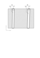
- FIG. 2 is a diagram showing an example of a captured image generated by the imaging device shown in FIG. 1.
- FIG. 2A is a diagram showing an example of a reference object area in the captured image shown in FIG. 2A.
- FIG. FIG. 2 is a schematic diagram showing details of the invisible region complementing section shown in FIG. 1;
- FIG. 7 is a diagram showing another example of a reference object area.
- 4A is a diagram showing an example of a shaped area obtained by shaping the reference object area shown in FIG. 4A.
- FIG. 4B is a diagram illustrating an example of an extended shaping area that is an extension of the shaping area shown in FIG. 4B.
- FIG. FIG. 7 is a diagram showing still another example of a reference object area.
- FIG. 5A is a diagram showing an example of a shaped area obtained by shaping the reference object area shown in FIG. 5A.
- FIG. 5B is a diagram illustrating an example of an extended shaping area that is an extension of the shaping area shown in FIG. 5B.
- FIG. 7 is a diagram showing still another example of a reference object area.
- FIG. 2 is a schematic diagram showing details of the pixel resolution estimation section shown in FIG. 1.
- FIG. 8 is a diagram for explaining an example of the number of interval pixels counted by the interval pixel number counting section shown in FIG. 7;
- FIG. 8 is a diagram for explaining another example of the number of interval pixels counted by the interval pixel number counting section shown in FIG. 7;
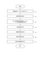
- FIG. 2 is a flowchart showing an example of the operation of the estimation device shown in FIG. 1.
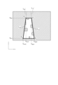
- FIG. 10 is a flowchart showing details of step S4 and step S5 shown in FIG. 9. It is a hardware block diagram of an estimation device.
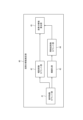
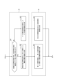
- an estimation system 100 includes an imaging device 1 and an estimation device 2.
- the imaging device 1 may be configured by a camera including an optical element, an image sensor, and an output interface.
- the output interface is an interface for outputting information.
- the imaging device 1 generates a captured image of a subject including a reference object S extending in real space, as shown in FIG. 2A.
- the subject is an object or the like that is imaged by the imaging device 1.
- the reference object S is an object attached to a predetermined structure among the subjects.
- the structure can be, for example, a tunnel, an underground tunnel for laying communication cables. Further, the structure may be a tunnel, a manhole, etc. for laying gas pipes, power transmission lines, etc. In a configuration where the structure is a tunnel, the reference object S can be a flat plate-like metal object fixed to the wall of the tunnel.
- the imaging device 1 may be mounted on a movable device such as a drone.
- pixels are arranged in the captured image in the y-axis direction (first direction) and the x-axis direction (second direction) orthogonal to the y-axis direction.
- the y-axis direction is a direction in the captured image that corresponds to the direction in which the reference object S extends.
- a direction in a captured image that corresponds to the extending direction of the reference object S refers to the direction in the captured image that corresponds to the extending direction of the reference object S among the x-axis direction and y-axis direction in which pixels are arranged in the captured image. This is the direction with the smaller angle.
- the format of the captured image may be arbitrary.
- the imaging device 1 outputs captured image data indicating the captured image to the estimation device 2.
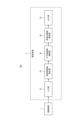
- the estimation device 2 includes an input section 10, a reference object region detection section 20, an invisible region complementation section 30, a pixel resolution estimation section 40, and an output section 50.
- the input unit 10 is configured by an input interface.
- the input interface can be an interface that accepts input of information output from other devices.
- Input interfaces may include communication interfaces that receive information from other devices. For example, standards such as Ethernet (registered trademark), FDDI (Fiber Distributed Data Interface), and Wi-Fi (registered trademark) may be used for the communication interface.
- the reference object region detection section 20, the invisible region complementation section 30, and the pixel resolution estimation section 40 are configured by a controller.
- the controller may be configured with dedicated hardware such as an ASIC (Application Specific Integrated Circuit) or an FPGA (Field-Programmable Gate Array), a processor, or a combination of both. good.
- the output unit 50 is configured by an output interface. Output interfaces may include communication interfaces that transmit information to other devices.
- the input unit 10 receives input of captured image data indicating a captured image generated by the imaging device 1.
- the reference object area detection unit 20 detects a reference object area (in the example of FIG. 2B, The area shown in white) is detected. Specifically, the reference object area detection unit 20 can detect the reference object area by using machine learning, deep learning, or the like. Note that hereinafter, an area that is not detected as a reference object area in a captured image may be referred to as a non-reference object area.
- the reference object area is composed of a plurality of pixels among the pixels that constitute the image pickup. Preferably, all of the plurality of pixels constituting the reference object area are included in the reference object area. In other words, the reference object area is arranged such that a part of any one pixel among the plurality of pixels constituting the reference object S is included in the reference object area and the remaining part is not included in the reference object area. Preferably, it is not configured.
- the invisible region complementing section 30 includes a region determining section 31, a reference object shape standardization section 32, and a shape extension section 33.
- the reference object S In real space, other objects may be placed between the reference object S and the imaging device 1.
- the other object is a metal support, a cable, or the like.
- FIG. 2A a part of the image of the reference object S is not shown in the captured image, and the image showing the single reference object S is divided. Therefore, as shown in FIG. 2B, the reference object area detecting section 20 described above divides the reference object area constituting the image of one reference object into areas surrounded by thick circles, and divides the reference object area into a plurality of reference objects. It is detected as object region R0.
- the area determination unit 31 determines one or more reference object regions that constitute the image of the single reference object S based on the positional relationship of the one or more reference object regions. Specifically, first, the region determination unit 31 determines whether a plurality of reference object regions are arranged adjacent to each other in a direction corresponding to the extending direction of the reference object S.
- the area determination unit 31 determines that the plurality of reference object regions are not arranged adjacent to each other in the direction corresponding to the extending direction of the reference object S. If the area determination unit 31 determines that one reference object region is a single reference object S. It is determined that the image of When determining that the plurality of reference object regions are arranged adjacent to each other in the direction corresponding to the extending direction of the reference object S, the region determination section 31 determines whether the plurality of reference object regions are arranged next to each other in the direction corresponding to the extending direction of the reference object S, based on the distance between the plurality of reference object regions. , it is determined that the plurality of reference object regions constitute an image of a single reference object S.
- the area determination unit 31 determines the area between the extension lines of the center lines of the plurality of reference object areas, which are arranged in the direction corresponding to the extending direction of the reference object S. It is determined whether the length is less than or equal to a predetermined value.
- the center line is a straight line that passes through the coordinates obtained by averaging the coordinates (x coordinates) of the midpoint of the reference object region in the x-axis direction.
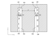
- the area determination unit 31 determines the reference object area that constitutes the image of the single reference object S based on the positional relationship between the plurality of reference object areas R01 and R02. Specifically, the region determination unit 31 determines whether the reference object regions R01 and R02 are located adjacent to each other in the direction corresponding to the extending direction of the reference object S (the y-axis direction in the example of FIG. 4A). It is determined whether the length d01 between the extension lines of the center lines LN1 and LN2 of the reference object regions R01 and R02, respectively, is equal to or less than a predetermined value.
- the region determination unit 31 determines that the plurality of reference object regions R01 and R02 constitute an image of a single reference object S.
- the region determination unit 31 determines that the plurality of reference object regions R01 and R02 do not constitute an image of a single reference object S.
- the area determination unit 31 is configured to detect reference object areas that are arranged adjacent to each other in a direction corresponding to the extending direction of the reference object S (the y-axis direction in the example of FIG. 4A). It is determined whether a length d02 between R03 and R04, an extension of the center lines LN3 and LN4 of each of the reference object regions R03 and R04, is less than or equal to a predetermined value. Then, when the length d02 is determined to be less than or equal to the predetermined value, the region determination unit 31 determines that the plurality of reference object regions R03 and R04 constitute an image of a single reference object S. If the length d02 is determined to be longer than the predetermined value, the area determination unit 31 determines that the plurality of reference object regions do not constitute an image of a single reference object S.
- the area determining unit 31 determines that the length between a plurality of reference object regions arranged adjacent to each other in the direction corresponding to the extending direction of the reference object S is It is determined whether the length is shorter than the length between a plurality of reference object regions arranged adjacent to each other in a direction orthogonal to the direction corresponding to the direction.
- the region determination unit 31 selects a plurality of reference object regions R01 that are arranged adjacent to each other in a direction corresponding to the extending direction of the reference object S (in the example of FIG. 4A, the y-axis direction).
- a plurality of reference object regions R01 and R02 are arranged adjacent to each other in a direction perpendicular to a direction corresponding to the extending direction of the reference object S (in the example of FIG. 4A, the x-axis direction). It is determined whether the length between R03 is shorter than the length d2.
- the region determination unit 31 determines that the plurality of reference object regions R01 and R02 constitute an image of a single reference object S. Further, the region determination unit 31 determines that the plurality of reference object regions R01 and R02 do not constitute an image of a single reference object S.
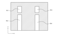
- the reference object shape specification section 32 generates a shaped region by shaping the reference object region detected by the reference object region detection section 20 based on the shape of the reference object S in real space. Specifically, as shown in FIG. 4A, when it is determined that a plurality of reference object regions constitute an image of a single reference object S, the reference object shape standard section 32 specifies the image as shown in FIG. 4B. Next, a plurality of shaped regions are generated by shaping each of the plurality of reference object regions. Further, as shown in FIG. 5A, when it is determined that one reference object region constitutes an image of a single reference object S, the reference object shape standard section 32 One shaping area is generated by shaping two reference object areas.
- the reference object shape standard unit 32 generates a shaping region that circumscribes the reference object region as shown in FIG. 4A and has a rectangle with the minimum area as the periphery, as shown in FIG. 4B. can do.
- FIG. 4A is an example in which it is determined that a plurality of reference object regions constitute an image of a single reference object S
- the reference object shape standard section 32 may, for example, Even when it is determined that two reference object regions constitute an image of a single reference object S, as shown in FIG. generate.
- the reference object shape standard section 32 determines a maximum coordinate y max and a minimum coordinate y min in the y-axis direction from the reference object region (the region shown in white in the example of FIG. 6). Detect. Then, the reference object shape standard section 32 determines two points P 1 and P 2 located at the maximum coordinate x max1 and the minimum coordinate x min 1 in the x-axis direction at the maximum coordinate y max in the y-axis direction, and the minimum coordinate in the y-axis direction. Two points P 3 and P 4 having the maximum coordinate x max2 and the minimum coordinate x min2 in the x-axis direction at the coordinate y min are extracted.
- the reference object shape standard section 32 can generate a shaped region by shaping the reference object region into a trapezoid having the four extracted points P 1 , P 2 , P 3 , and P 4 as vertices.
- the reference object shape standard section 32 shapes the shaping region by shaping the reference object region into a trapezoid, but the present invention is not limited to this, and the maximum coordinate y max and the minimum coordinate y min in the y-axis direction are , and a rectangular shaped area having vertices at points based on the maximum coordinate x max and the minimum coordinate x min in the x-axis direction.
- the reference object shape standard section 32 may generate a shaping area according to the above example, or may generate a shaping area according to another example above, based on the shape information input by the input section 10. You can. That is, the reference object shape standard section 32 can generate a rectangular shaped area, and when the shape indicated by the shape information is a rectangle, generates a shaped area in which the reference object area is shaped into a rectangle. Further, when the shape indicated in the shape information is a trapezoid, the reference object shape standard section 32 generates a shaped region by shaping the reference object region into a trapezoid. Further, when the shape indicated in the shape information is another quadrangle, the reference object shape standard section 32 generates a shaped region by shaping the reference object region into the other quadrangle.
- the shape extension unit 33 generates an extended shaping region by extending the shaping region in a direction in the captured image that corresponds to the extending direction of the reference object S in real space.
- the direction corresponding to the extending direction of the reference object S is the y-axis direction
- the shape extension portion 33 extends the shaping region in the y-axis direction.
- the reference object shape standard section 32 corrects the reference object region to a rectangular shape
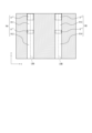
- a plurality of reference object regions constitute an image of a single reference object S as shown in FIG. 4A. If it is determined, the shape extension part 33 applies a shape to the plurality of shaping regions R11 and R12 constituting the image of the single reference object S, as shown in FIG. 4C, between the plurality of shaping regions R11 and R12.
- An extended shaping area RA is generated by adding the first complementary area R +1 located at , and the second complementary area R +2 located between the shaping area R11 and the edge of the captured image.
- the shape extension section 33 provides a first complementary region located between the plurality of shaping regions R13 and R14 forming the image of the single reference object S.
- An extended reshaping region RB is generated by adding R +1 and a second complementary region R +2 located between the reshaping region R13 and the edge of the captured image.
- the shape extension section 33 is generated by the reference object shape standard section 32.
- an extended shaping region is generated by adding a second complementary region R +2 located between the shaping region R11 and the edge of the captured image to one shaping region R11.
- the shape extension section 33 applies one shaping region R12 generated by the reference object shape standardization section 32 to a second shaping region R12 located between the shaping region R12 and the edge of the captured image, as shown in FIG. 5C.
- An extended shaping area is generated by adding 2 complementary areas R + 2.
- the shape extension section 33 extends the shaping region in the direction corresponding to the extending direction of the reference object.
- the shape extension portion 33 extends the line segments L 13 and L 24 that are opposed to each other and are not parallel to each other, as shown in FIG. 6 (the extension line shown in FIG. 6 L 13 ′ and L 24 ′).
- Line segment L 13 is a line segment that connects vertices P 1 and P 2
- line segment L 24 is a line segment that connects vertices P 2 and P 4 .
- the shape extension unit 33 generates a trapezoidal region surrounded by the two extension lines L 13 ′ and L 24 ′ and the line segment serving as the end of the captured image as an extension shaping region.
- the pixel resolution estimating section 40 includes a reference object number counting section 41, a width pixel number counting section 42, a thinning section 43, an interval pixel number counting section 44, and a pixel resolution calculating section 45. has.
- the reference object number counting section 41 counts the number of extended shaping regions generated by the invisible region complementing section 30.
- the width pixel count unit 42 counts the number of width pixels in the captured image, which corresponds to the length of the reference object S in the direction (width direction) orthogonal to the extending direction.
- the width pixel count may be the pixel count in a direction orthogonal to the extending direction of the reference object area in the captured image.
- the number of width pixels may be the number of pixels in the x-axis direction of the captured image.
- the thinning unit 43 determines the center line of each of the plurality of extension shaping regions.
- the center line determined by the thinning unit 43 is a line segment formed by a set of midpoints of both ends in the x-axis direction in the extended shaping region.
- the thinning unit 43 determines the center line LNA in the extended shaping area RA, and determines the center line LNB in the extended shaping area RB.
- the interval pixel count unit 44 counts the interval pixel number c, which is the number of pixels between the plurality of center lines LNA and LNB determined by the thinning unit 43, as shown in FIG. 8A.
- the interval pixel count unit 44 can count the interval pixel number c at a plurality of predetermined positions in the y-axis direction. Specifically, the interval pixel count unit 44 calculates a first position y1 in the y-axis direction, a second position y2 different from the first position, and a difference between the first position y1 and the second position y2. The interval pixel counts c1, c2, and c3 may be measured at each of the different third positions y3.
- the pixel resolution calculation unit 45 calculates the pixel resolution, which is the ratio of the length of the subject to the length of the pixels constituting the captured image, based on the shaping area.
- the pixel resolution calculation section 45 may calculate the pixel resolution based on the extended shaped region generated by the shape extension section 33 by extending the shaped region.
- the pixel resolution calculation unit 45 can calculate the pixel resolution Rp based on the width pixel number a and the width b of the portion of the reference object S corresponding to the width pixel number a. For example, the pixel resolution calculation unit 45 can calculate the pixel resolution Rp by dividing the width b by the number of width pixels a, as shown in equation (1) below.
- the width b of the reference object S is a known value, and may be a value input by an input interface.
- the pixel resolution calculation unit 45 also calculates the number of pixels c between the center lines LNA and LNB determined by the thinning unit 43, and the length of the subject in real space corresponding to the number c of pixels c. Based on d, a pixel resolution Rp indicating the length of real space relative to the length of a pixel may be calculated.
- the interval pixel number counting unit 44 calculates the pixel resolution Rp by dividing the length d of the subject in real space corresponding to the interval pixel number c by the interval pixel number c, as shown in the following equation (2). Calculate.
- the length d may be a known value, such as a value input by an input interface.
- the pixel The resolution calculation unit 45 may calculate the pixel resolutions Rp1 to Rpn by dividing the interval pixel numbers c1 to cn by the length d for each of a plurality of predetermined positions. In real space, even if the intervals between the plurality of reference objects S are constant, the center line LNA and The interval pixel number c between LNBs may be different.
- the interval pixel number counting section 44 counts the interval pixel number c for each position of the captured image, so that the pixel resolution calculation section 45 calculates the pixel resolution Rp for each position of the captured image. be able to.
- the pixel resolution calculation unit 45 The overall pixel resolution Rp can be calculated. Therefore, the estimation device 2 can calculate the pixel resolution Rp with high accuracy, and the magnitude of deformation in the subject can be estimated with high accuracy by using this pixel resolution Rp.
- the width pixel count section 42 counts the width pixel number a
- the pixel resolution calculation section 45 calculates the width pixel number a based on the width pixel number a. Calculate pixel resolution Rp.
- the width pixel count section 42 counts the width pixel number a
- the pixel resolution calculation section 45 calculates the pixel resolution Rp based on the width pixel number a.
- the thinning unit 43 determines the center line
- the interval pixel count unit 44 counts the interval pixel number c
- the pixel resolution calculation unit 45 calculates the pixel resolution Rp based on the interval pixel number c. It may be calculated.
- the pixel resolution calculation unit 45 can calculate the pixel resolution Rp based on the interval pixel number c with higher precision than when calculating the pixel resolution Rp based on the width pixel number a. Therefore, when the number of extension shaping areas is plural, it is preferable that the pixel resolution calculation unit 45 calculates the pixel resolution Rp based on the interval pixel number c rather than the width pixel number a. It is preferable that the line thinning unit 43 and the interval pixel number counting unit 44 execute the process instead of the counting unit 42.
- the output unit 50 outputs pixel resolution information including the pixel resolution Rp calculated by the pixel resolution calculation unit 45.
- the pixel resolution information may further include information indicating the position of the pixel where the image of the subject is displayed at the pixel resolution Rp, as well as the pixel resolution Rp.
- the pixel resolution information output by the output unit 50 may be stored in a storage device including a memory.
- FIGS. 9 and 10 are flowcharts showing an example of the operation of the estimation device 2 according to this embodiment.
- the operation of the estimation device 2 described with reference to FIGS. 9 and 10 corresponds to an example of the estimation method of the estimation device 2 according to the present embodiment.
- step S1 the input unit 10 inputs captured image data indicating a captured image generated by capturing a reference object S extending in one direction in real space using the imaging device 1. Accept input.
- the reference object region detection unit 20 detects a reference object that is a region showing at least a part of the image of the reference object S in a captured image generated by imaging the reference object S extending in real space. Detect areas.
- step S3 the region determination unit 31 determines one or more reference object regions that constitute the image of the single reference object S.
- step S4 the reference object shape standard section 32 generates a shaped region by shaping the reference object region into a shape corresponding to the shape of the reference object S.
- step S5 the shape extension unit 33 generates an extended shaping area by extending the shaping area in the direction in the captured image that corresponds to the extending direction of the reference object S in real space.
- step S4 the process of generating a shaping area in step S4 and the process of generating an extended shaping area in step S5 will be described in detail.
- step S41 the reference object shape standard section 32 determines whether the region determination section 31 has determined that a plurality of reference object regions constitute an image of a single reference object S.
- step S41 If it is determined in step S41 that the area determination section 31 has determined that a plurality of reference object regions forming the image of a single reference object S has been determined, in step S42, the reference object shape standardization section 32 A plurality of shaped areas are generated by shaping each of the reference object areas.
- step S51 the shape extension unit 33 applies a first complementary region located between the plurality of shaping regions and a second complementary region located between the shaping region and the edge of the captured image to the plurality of shaping regions. Generate an extended shaped area by adding the area.
- step S43 the reference object shape standard section 32 selects one reference object region. Generates one formatted area by formatting.
- step S52 the shape extension unit 33 generates an extended shaping area by adding a second complementary area between the one shaping area and the edge of the captured image to one shaping area.
- the reference object shape standard section 32 may generate a shaping region whose periphery is a rectangle with the smallest area that circumscribes the reference object region, or, as described above, A shaped area may be generated by shaping the object area into a trapezoid.
- the pixel resolution calculation unit 45 calculates the pixel resolution, which is the ratio of the length of the subject to the length of the pixels constituting the captured image, based on the shaping area.
- the pixel resolution calculation unit 45 may calculate the pixel resolution based on the extended shaping area.
- step S7 the output unit 50 outputs pixel resolution information including the pixel resolution calculated by the pixel resolution calculation unit 45.
- the estimation device 2 shows at least a part of the image of the reference object S in the captured image generated by capturing the reference object S extending in real space.
- a reference object area detection unit 20 that detects a reference object area that is a region;
- a reference object shape standard unit 32 that generates a shaping area by shaping the reference object area into a shape corresponding to the shape of the reference object S;
- a pixel resolution calculation unit 45 is provided, which calculates a pixel resolution that is the ratio of the length of the subject to the length of the pixels constituting the captured image.
- the estimation device 2 can calculate the pixel resolution, which is the ratio of the length of the subject to the length of the pixels forming the captured image, with high accuracy. Therefore, by using the pixel resolution, the size of the deformation shown in the captured image in real space can be estimated with high accuracy.
- the estimation device 2 of the present embodiment generates a shaping region corresponding to the entire portion corresponding to the reference object S, and thereby the length related to the reference object S in real space (in the above example, width, interval), pixel resolution Rp can be calculated.
- a correction region is not generated by correcting the reference object region, a plurality of center lines may be extracted when extracting the center line in the reference object region used to calculate the pixel resolution Rp. In this case, it may become impossible to determine which of the plurality of center lines should be used to calculate the pixel resolution Rp.
- the estimation device 2 of the present embodiment since the estimation device 2 of the present embodiment generates a correction region by correcting the reference object region, it is difficult to appropriately extract one center line from the reference object region corresponding to one reference object S. can. Accordingly, the estimation device 2 can appropriately calculate the pixel resolution Rp.
- the estimation device 2 includes a shape extension unit 33 that generates an extended shaping region by extending the shaping region in the direction in the captured image corresponding to the extending direction of the reference object S in real space. Furthermore, it is equipped with.
- the pixel resolution calculation unit 45 calculates the pixel resolution based on the extended shaping area. Thereby, the estimation device 2 can calculate the pixel resolution in the portion where the image of the reference object S is not shown in the captured image. Therefore, even in a portion where the image of the reference object S is not shown in the captured image, the size of the deformation shown in the portion in real space can be calculated.
- the estimation device 2 By generating the extended shaping area, one extended shaping area that constitutes the image of the single reference object S is generated. Therefore, the estimation device 2 can accurately determine the number of reference objects S whose images are shown in the captured image.
- the estimation device 2 may further include a storage unit, and the storage unit stores the captured image data input by the input unit 10.
- the reference object area detection unit 20 may detect the reference object area indicated by the captured image data stored in the storage unit.
- FIG. 11 is a block diagram showing a schematic configuration of computers 601 each functioning as the estimation device 2.
- the computer 601 may be a general-purpose computer, a dedicated computer, a workstation, a PC (Personal Computer), an electronic notepad, or the like.
- Program instructions may be program code, code segments, etc. to perform necessary tasks.
- the computer 601 includes a processor 610, a ROM (Read Only Memory) 620, a RAM (Random Access Memory) 630, a storage 640, an input section 650, a display section 660, and a communication interface ( I/F) 670.
- the processor 610 is a CPU (Central Processing Unit), MPU (Micro Processing Unit), GPU (Graphics Processing Unit), DSP (Digital Signal Processor), SoC (System on a Chip), etc., and may be of the same or different type. It may be configured with a plurality of processors.
- the processor 610 controls each component and executes various calculation processes. That is, the processor 610 reads a program from the ROM 620 or the storage 640 and executes the program using the RAM 630 as a work area. The processor 610 controls each of the above components and performs various arithmetic operations according to a program stored in the ROM 620 or the storage 640. In the embodiments described above, the program according to the present disclosure is stored in the ROM 620 or the storage 640.
- the program may be stored in a storage medium readable by the computer 601. Using such a storage medium, it is possible to install a program on the computer 601.
- the storage medium in which the program is stored may be a non-transitory storage medium.
- the non-temporary storage medium is not particularly limited, and may be, for example, a CD-ROM, a DVD-ROM, a USB (Universal Serial Bus) memory, or the like. Further, this program may be downloaded from an external device via a network.
- the ROM 620 stores various programs and various data.
- the RAM 630 temporarily stores programs or data as a work area.
- the storage 640 is configured with an HDD (Hard Disk Drive) or an SSD (Solid State Drive), and stores various programs including an operating system and various data.
- the input unit 650 includes one or more input interfaces that accept a user's input operation and obtain information based on the user's operation.
- the input unit 650 is a pointing device, a keyboard, a mouse, etc., but is not limited to these.
- the display unit 660 includes one or more output interfaces that output information.
- the display unit 660 is a display that outputs information as a video or a speaker that outputs information as an audio, but is not limited to these.
- the display section 660 also functions as the input section 650 if it is a touch panel type display.
- the communication interface (I/F) 670 is an interface for communicating with an external device.
- a controller comprising: Detecting a reference object area that is an area showing at least a part of the image of the reference object in a captured image generated by imaging a subject including the reference object extending in real space; generating a shaped area in which the reference object area is shaped into a shape corresponding to the shape of the reference object; An estimation device that calculates a pixel resolution that is a ratio of a length of the subject in the real space to a length of pixels constituting the captured image based on the shaping area.
- the controller includes: generating an extended shaping area by extending the shaping area in a direction in the captured image corresponding to an extending direction of the reference object in the real space;
- the estimation device according to supplementary note 1, which calculates the pixel resolution based on the extended shaping area.
- the controller includes: determining one or more reference object regions that constitute a single image of the reference object based on the positional relationship of the one or more reference object regions; If it is determined that a plurality of reference object regions constitute a single image of the reference object, generating a plurality of shaped regions by shaping each of the plurality of reference object regions; an extended shaping area that is the plurality of shaping areas plus a first complementary area located between the plurality of shaping areas and a second complementary area located between the shaping area and the edge of the captured image; generate, If it is determined that one reference object region constitutes a single image of the reference object, generating one shaping area by shaping the one reference object area;
- the estimating device according to supplementary note 2, which generates an extended shaping region that is the one shaping region plus a second complementary region located between the shaping region and an edge of the captured image.
- An imaging device that images a subject including a reference object extending in real space to generate a captured image
- the estimation device includes a controller, and the controller includes: detecting a reference object area in the captured image that is an area showing at least a part of the image of the reference object; generating a shaped area in which the reference object area is shaped into a shape corresponding to the shape of the reference object; An estimation device that calculates a pixel resolution that is a ratio of a length of the subject in the real space to a length of pixels constituting the captured image based on the shaping area.
- Imaging device 2 Estimation device 10 Input unit 20 Reference object area detection unit 30 Invisible area complementation unit 31 Area determination unit 32 Reference object shape specification unit 33 Shape extension unit 40 Pixel resolution estimation unit 41 Reference object number counting unit 42 Width pixel number count Section 43 Thinning section 44 Interval pixel count section 45 Pixel resolution calculation section 50 Output section 100 Estimation system 601 Computer 610 Processor 620 ROM 630 RAM 640 Storage 650 Input section 660 Output section 670 Communication interface 680 Bus
Landscapes
- Physics & Mathematics (AREA)
- General Physics & Mathematics (AREA)
- Engineering & Computer Science (AREA)
- Geometry (AREA)
- Computer Vision & Pattern Recognition (AREA)
- Theoretical Computer Science (AREA)
- Image Processing (AREA)
Abstract
本開示に係る推定装置(2)は、実空間において延在している基準物を撮像して生成された撮像画像における、基準物の像の少なくとも一部を示す領域である基準物領域を検出する基準物領域検出部(20)と、基準物領域を、基準物の形状に対応する形状に整形した整形領域を生成する基準物形状規格部(32)と、整形領域に基づいて、撮像画像を構成する画素の長さに対する、被写体の長さの比である画素分解能を算出する画素分解能算出部(45)と、を備える。
Description
本開示は、推定装置、推定システム、推定方法、及びプログラムに関する。
構造物の点検を効率化するために画像処理を用いることが検討されている。具体的には、撮像画像から、ひび割れ、露出鉄筋等の像を検出することによって、構造物の劣化部分を推定する技術が提案されている。近年では、深層学習におけるセグメンテーション手法が用いて構造物の劣化を推定することも知られている。
また、構造物の点検において、撮像画像から構造物の劣化部分を推定するだけでは十分ではない。劣化部分を復旧させるために、劣化部分における損傷状況、補修範囲等を把握することが求められている。そのため,例えば、非特許文献1には、コンクリート表面のひび割れと同条件で撮影したクラックスケールを用いてひび割れ幅を抽出する技術が記載されている。
藤田雄介、外2名、「コンクリート構造物の外観検査のための画像合成および半自動ひび割れ評価」、土木学会論文集F3(土木情報学)、Vol.74、No1、18-32、2018
しかしながら、撮像画像から検出された劣化部分の大きさをより高い精度で評価する必要がある。
かかる事情に鑑みてなされた本開示の目的は、高い精度で、撮像画像を構成する画素の長さに対する、被写体の長さの比である画素分解能を算出することができる推定装置、推定システム、推定方法、及びプログラムを提供することにある。
上記課題を解決するため、本開示に係る推定装置は、実空間において延在している基準物を撮像して生成された撮像画像における、前記基準物の像の少なくとも一部を示す領域である基準物領域を検出する基準物領域検出部と、前記基準物領域を、前記基準物の形状に対応する形状に整形した整形領域を生成する基準物形状規格部と、前記整形領域に基づいて、前記撮像画像を構成する画素の長さに対する、前記被写体の長さの比である画素分解能を算出する画素分解能算出部と、を備える。
また、上記課題を解決するため、本開示に係る推定システムは、実空間において延在している基準物を含む被写体を撮像して撮像画像を生成する撮像装置と、推定装置と、を備え、前記推定装置は、前記撮像画像における、前記基準物の像の少なくとも一部を示す領域である基準物領域を検出する基準物領域検出部と、前記基準物領域を、前記基準物の形状に対応する形状に整形した整形領域を生成する基準物形状規格部と、前記整形領域に基づいて、前記撮像画像を構成する画素の長さに対する、前記実空間における前記被写体の長さの比である画素分解能を算出する画素分解能算出部と、を有する。
また、上記課題を解決するため、本開示に係る推定方法は、推定装置が実行する推定方法において、実空間において延在している基準物を撮像して生成された撮像画像における、前記基準物の像の少なくとも一部を示す領域である基準物領域を検出するステップと、
前記基準物領域を、前記基準物の形状に対応する形状に整形した整形領域を生成するステップと、前記整形領域に基づいて、前記撮像画像を構成する画素の長さに対する、前記被写体の長さの比である画素分解能を算出するステップと、を含む。
前記基準物領域を、前記基準物の形状に対応する形状に整形した整形領域を生成するステップと、前記整形領域に基づいて、前記撮像画像を構成する画素の長さに対する、前記被写体の長さの比である画素分解能を算出するステップと、を含む。
また、上記課題を解決するため、本開示に係るプログラムは、コンピュータを上述した推定装置として機能させる。
本開示に係る推定装置、推定システム、推定方法、及びプログラムによれば、高い精度で、撮像画像を構成する画素の長さに対する、被写体の長さの比である画素分解能を算出することができる。
図1に示すように、本実施形態に係る推定システム100は、撮像装置1と、推定装置2とを備える。
撮像装置1は、光学素子、撮像素子、及び出力インターフェースを備えるカメラによって構成されてもよい。出力インターフェースは、情報を出力するためのインターフェースである。
撮像装置1は、図2Aに示すような、実空間において延在している基準物Sを含む被写体を撮像した撮像画像を生成する。被写体は、撮像装置1によって撮像される物体等である。基準物Sは、被写体のうちの予め定められている、構造物に取り付けられている物体である。構造物は、例えば、通信ケーブル敷設用の地下トンネルであるとう道とすることができる。また、構造物は、ガス管、送電線等の敷設用のトンネル、マンホール等であってもよい。構造物がとう道である構成において、基準物Sは、とう道の壁面に固定された平板状の筋金物とすることができる。また、撮像装置1は、ドローン等の移動可能な装置に搭載されていてもよい。
図2Aに示すように、撮像画像には、y軸方向(第1の方向)、及びy軸方向に直交するx軸方向(第2の方向)に画素が配列されている。y軸方向は、基準物Sの延在方向に対応する、撮像画像での方向である。「基準物Sの延在方向に対応する、撮像画像での方向」とは、撮像画像において画素が配列されているx軸方向及びy軸方向のうち、基準物Sの延在方向とのなす角が小さい方の方向である。また、撮像画像の形式は任意であってよい。
また、撮像装置1は、撮像画像を示す撮像画像データを推定装置2に出力する。
<推定装置の構成>
推定装置2は、入力部10と、基準物領域検出部20と、不可視領域補完部30と、画素分解能推定部40と、出力部50とを備える。
推定装置2は、入力部10と、基準物領域検出部20と、不可視領域補完部30と、画素分解能推定部40と、出力部50とを備える。
入力部10は、入力インターフェースによって構成される。入力インターフェースは、他のデバイスから出力された情報の入力を受け付けるインターフェースとすることができる。入力インターフェースは、他の装置から情報を受信する通信インターフェースを含んでもよい。通信インターフェースには、例えば、イーサネット(登録商標)、FDDI(Fiber Distributed Data Interface)、Wi-Fi(登録商標)等の規格が用いられてもよい。基準物領域検出部20、不可視領域補完部30、及び画素分解能推定部40は、コントローラによって構成される。コントローラは、ASIC(Application Specific Integrated Circuit)、FPGA(Field-Programmable Gate Array)等の専用のハードウェアによって構成されてもよいし、プロセッサによって構成されてもよいし、双方を含んで構成されてもよい。出力部50は、出力インターフェースによって構成される。出力インターフェースは、他の装置に情報を送信する通信インターフェースを含んでもよい。
入力部10は、撮像装置1によって生成された撮像画像を示す撮像画像データの入力を受け付ける。
基準物領域検出部20は、入力部10によって入力が受け付けられた撮像画像データが示す撮像画像における、基準物Sの像の少なくとも一部を示す領域である基準物領域(図2Bの例では、白色で示す領域)を検出する。具体的には、基準物領域検出部20は、機械学習、深層学習等を用いることにより基準物領域を検出することができる。なお、以降において、撮像画像における基準物領域として検出されなかった領域を非基準物領域ということがある。
なお、基準物領域は、撮像を構成する画素のうちの複数の画素によって構成されている。基準物領域を構成する複数の画素はいずれも該画素の全体が基準物領域に含まれていることが好ましい。すなわち、基準物Sを構成する複数の画素のうち、いずれか1つの画素の一部が基準物領域に含まれ、残りの一部が基準物領域に含まれていないように、基準物領域が構成されないことが好ましい。
図3に示すように、不可視領域補完部30は、領域判定部31と、基準物形状規格部32と、形状延長部33とを有する。
実空間において、基準物Sと撮像装置1との間に他の物体が配置されていることがある。例えば、構造物がとう道であり、基準物Sが筋金物である構成において、他の物体は、受金物、ケーブル等である。このような場合、図2Aに示すように、撮像画像において、基準物Sの像の一部が示されず、単一の基準物Sを示す像が分断されている。このため、上述した基準物領域検出部20によって、図2Bに示すように、1つの基準物の像を構成する基準物領域が太線の丸で囲まれている領域で分断されて、複数の基準物領域R0として検出される。
そこで、領域判定部31は、1以上の基準物領域の位置関係に基づいて、単一の基準物Sの像を構成している、1以上の基準物領域を判定する。具体的には、まず、領域判定部31は、複数の基準物領域が、基準物Sの延在方向に相当する方向に互いに隣り合って配置されているか否かを判定する。
領域判定部31は、複数の基準物領域が、基準物Sの延在方向に相当する方向に互いに隣り合って配置されていないと判定した場合、1つの基準物領域が単一の基準物Sの像を構成していると判定する。領域判定部31は、複数の基準物領域が、基準物Sの延在方向に相当する方向に互いに隣り合って配置されていると判定した場合、複数の基準物領域の間の距離に基づいて、該複数の基準物領域が単一の基準物Sの像を構成していると判定する。
一例として、領域判定部31は、基準物Sの延在方向に対応する方向に配列されている複数の基準物領域の間における、該複数の基準物領域それぞれの中心線の延長線の間の長さが、所定値以下であるか否かを判定する。ここで、中心線とは、基準物領域のx軸方向での中点の座標(x座標)を平均化した座標を通る直線である。
図4Aの例について説明すると、領域判定部31は、複数の基準物領域R01及びR02の位置関係に基づいて、単一の基準物Sの像を構成している基準物領域を判定する。具体的には、領域判定部31は、基準物Sの延在方向に対応する方向(図4Aの例ではy軸方向)で互いに隣り合って配置されている、基準物領域R01及びR02の間における、基準物領域R01及びR02それぞれの中心線LN1及びLN2の延長線の間の長さd01が、所定値以下であるか否かを判定する。そして、領域判定部31は、長さd01が所定値以下であると判定されると、複数の基準物領域R01及びR02が単一の基準物Sの像を構成していると判定する。領域判定部31は、長さd01が所定値より長いと判定されると、複数の基準物領域R01及びR02が単一の基準物Sの像を構成していないと判定する。
同様にして、領域判定部31は、領域判定部31は、基準物Sの延在方向に対応する方向(図4Aの例ではy軸方向)で互いに隣接して配置されている、基準物領域R03及びR04の間における、基準物領域R03及びR04それぞれの中心線LN3及びLN4の延長線の間の長さd02が、所定値以下であるか否かを判定する。そして、領域判定部31は、長さd02が所定値以下であると判定されると、複数の基準物領域R03及びR04が単一の基準物Sの像を構成していると判定する。領域判定部31は、長さd02が所定値より長いと判定されると、複数の基準物領域が単一の基準物Sの像を構成していないと判定する。
他の例として、領域判定部31は、基準物Sの延在方向に対応する方向で互いに隣り合って配置されている複数の基準物領域の間の長さが、基準物Sの延在方向に対応する方向の直交方向で互いに隣り合って配置されている複数の基準物領域の間の長さより短いか否かを判定する。
図4Aの例について説明すると、領域判定部31は、基準物Sの延在方向に対応する方向(図4Aの例ではy軸方向)に互いに隣り合って配置されている複数の基準物領域R01及びR02の間の長さd1が、基準物Sの延在方向に対応する方向の直交方向(図4Aの例ではx軸方向)に互いに隣り合って配置されている複数の基準物領域R01及びR03の間の長さd2より短いか否かを判定する。
そして、領域判定部31は、長さd1が長さd2より短いと判定されると、複数の基準物領域R01及びR02が単一の基準物Sの像を構成していると判定する。また、領域判定部31は、複数の基準物領域R01及びR02が単一の基準物Sの像を構成していないと判定する。
基準物形状規格部32は、基準物領域検出部20によって検出された基準物領域を、実空間における基準物Sの形状に基づいて整形した整形領域を生成する。具体的には、図4Aに示すように、複数の基準物領域が単一の基準物Sの像を構成していると判定された場合、基準物形状規格部32は、図4Bに示すように、複数の基準物領域それぞれを整形した複数の整形領域を生成する。また、図5Aに示すように、1つの基準物領域が単一の基準物Sの像を構成していると判定された場合、基準物形状規格部32は、図5Bに示すように、1つの基準物領域を整形した1つの整形領域を生成する。
一例として、基準物形状規格部32は、図4Aに示すような基準物領域を、図4Bに示すような、基準物領域に外接し、面積が最小となる矩形を周縁とする整形領域を生成することができる。なお、図4Aは複数の基準物領域が単一の基準物Sの像を構成していると判定された例であるが、基準物形状規格部32は、例えば、図5Aに示すように1つの基準物領域が単一の基準物Sの像を構成していると判定された場合も、図5Bに示すように、基準物領域に外接する、面積が最小の矩形に整形した整形領域を生成する。
他の例として、基準物形状規格部32は、図6に示すように、基準物領域(図6の例では白色で示される領域)から、y軸方向の最大座標ymax及び最小座標yminを検出する。そして、基準物形状規格部32は、y軸方向の最大座標ymaxにおけるx軸方向の最大座標xmax1及び最小座標xmin1それぞれに位置する2点P1及びP2と、y軸方向の最小座標yminにおけるx軸方向の最大座標xmax2及び最小座標xmin2となる2点P3及びP4とを抽出する。そして、基準物形状規格部32は、基準物領域を、抽出された4つの点P1、P2、P3、及びP4を頂点とする台形に整形した整形領域を生成することができる。なお、図6に示す例では、基準物形状規格部32は、基準物領域を台形に整形した整形領域を整形したが、これに限られず、y軸方向の最大座標ymax及び最小座標ymin、並びにx軸方向の最大座標xmax及び最小座標xminに基づく点を頂点とする四角形に整形した整形領域を生成することができる。
なお、基準物形状規格部32は、入力部10によって入力が受け付けられた形状情報に基づいて、上記の一例によって整形領域を生成してもよいし、上記の他の例によって整形領域を生成してもよい。すなわち、基準物形状規格部32は、四角形の整形領域を生成することができ、形状情報に示される形状が矩形である場合、基準物領域を矩形に整形した整形領域を生成する。また、基準物形状規格部32は、形状情報に示される形状が台形である場合、基準物領域を台形に整形した整形領域を生成する。また、基準物形状規格部32は、形状情報に示される形状が他の四角形である場合、基準物領域を該他の四角形に整形した整形領域を生成する。
形状延長部33は、実空間における基準物Sの延在方向に対応する、撮像画像での方向に、整形領域を延長した延長整形領域を生成する。図4A~4Cに示す例では、基準物Sの延在方向に相当する方向はy軸方向であり、形状延長部33は、整形領域をy軸方向に延長する。
上述したように、基準物形状規格部32が基準物領域を矩形に補正する構成において、図4Aに示すように、複数の基準物領域が単一の基準物Sの像を構成していると判定された場合、形状延長部33は、図4Cに示すように、単一の基準物Sの像を構成している複数の整形領域R11及びR12に、該複数の整形領域R11及びR12の間に位置する第1の補完領域R+1と、整形領域R11及び撮像画像の端部の間に位置する第2の補完領域R+2とを加えた延長整形領域RAを生成する。同様にして、形状延長部33は、単一の基準物Sの像を構成している複数の整形領域R13及びR14に、該複数の整形領域R13及びR14の間に位置する第1の補完領域R+1と、整形領域R13及び撮像画像の端部の間に位置する第2の補完領域R+2とを加えた延長整形領域RBを生成する。
また、図5Aに示すように、1つの基準物領域が単一の基準物Sの像を構成していると判定された場合、形状延長部33は、基準物形状規格部32によって生成された1つの整形領域R11に、図5Cに示すように、該整形領域R11及び撮像画像の端部の間に位置する第2の補完領域R+2を加えた延長整形領域を生成する。同様にして、形状延長部33は、基準物形状規格部32によって生成された1つの整形領域R12に、図5Cに示すように、該整形領域R12及び撮像画像の端部の間に位置する第2の補完領域R+2を加えた延長整形領域を生成する。
上述したように、基準物形状規格部32が基準物領域を台形に補正する構成においても、形状延長部33は、整形領域を、基準物の延在方向に対応する方向に延長する。具体的には、形状延長部33は、図6に示すような、互いに対向する線分であって、互いに平行でない線分L13及び線分L24をそれぞれ延長する(図6に示す延長線L13’及びL24’)。線分L13は、頂点P1及びP2を結ぶ線分であり、線分L24は、頂点P2及びP4を結ぶ線分である。そして、形状延長部33は、2つの延長線L13’及びL24’と撮像画像の端部となる線分とによって囲まれる台形の領域を延長整形領域として生成する。
図7に示すように、画素分解能推定部40は、基準物数カウント部41と、幅画素数カウント部42と、細線化部43と、間隔画素数カウント部44と、画素分解能算出部45とを有する。
基準物数カウント部41は、不可視領域補完部30によって生成された延長整形領域の数をカウントする。
幅画素数カウント部42は、基準物Sの延在方向の直交方向(幅方向)の長さに相当する、撮像画像における幅画素数をカウントする。幅画素数は、撮像画像における基準物領域の延在方向の直交方向での画素数であってもよい。他の例として、幅画素数は、撮像画像のx軸方向における画素数であってもよい。
細線化部43は、基準物数カウント部41によってカウントされた、延長整形領域の数が複数である場合に、複数の延長整形領域それぞれにおける中心線を決定する。細線化部43によって決定される中心線は、延長整形領域における、x軸方向の両端部の中点の集合によって構成される線分である。図4Cに示す例では、細線化部43は、延長整形領域RAにおける中心線LNAを決定し、延長整形領域RBにおける中心線LNBを決定する。
間隔画素数カウント部44は、図8Aに示すように、細線化部43によって決定された複数の中心線LNA及びLNBの間にある画素の数である間隔画素数cをカウントする。
また、間隔画素数カウント部44は、図8Bに示すように、y軸方向における複数の所定位置で、間隔画素数cをカウントすることができる。具体的には、間隔画素数カウント部44は、y軸方向における第1の位置y1、第1の位置とは異なる第2の位置y2、及び第1の位置y1及び第2の位置y2とは異なる第3の位置y3とのそれぞれにおいて、間隔画素数c1、c2、及びc3を測定してもよい。
画素分解能算出部45は、整形領域に基づいて、撮像画像を構成する画素の長さに対する、被写体の長さの比である画素分解能を算出する。画素分解能算出部45は、形状延長部33が整形領域を延長して生成した延長整形領域に基づいて画素分解能を算出してもよい。
具体的には、画素分解能算出部45は、幅画素数aと、該幅画素数aに対応する、基準物Sの部分の幅bとに基づいて、画素分解能Rpを算出することができる。例えば、画素分解能算出部45は、以下の式(1)に示すように、幅bを幅画素数aで除することによって画素分解能Rpを算出することができる。基準物Sの幅bは既知の値であって、入力インターフェースによって入力が受け付けられた値であってもよい。

また、画素分解能算出部45は、細線化部43によって決定された複数の中心線LNA及びLNBの間にある間隔画素数cと、該間隔画素数cに対応する実空間での被写体の長さdに基づいて、画素の長さに対する実空間の長さを示す画素分解能Rpを算出してもよい。
例えば、間隔画素数カウント部44は、以下の式(2)に示すように、間隔画素数cに対応する実空間での被写体の長さdを間隔画素数cで除することによって画素分解能Rpを算出する。長さdは既知の値であって、例えば、入力インターフェースによって入力が受け付けられた値であってもよい。

上述したように、間隔画素数カウント部44が、y軸方向における複数の所定位置で、間隔画素数c1~cn(上述した、図8Bの例では、n=3)をカウントする構成において、画素分解能算出部45は、複数の所定位置それぞれごとに間隔画素数c1~cnを長さdで除することによって画素分解能Rp1~Rpnを算出してもよい。実空間において、複数の基準物Sの間隔が一定であっても、基準物Sに対する撮像装置の設置角度に応じて、図8Bに示すように、撮像画像の位置に応じて、中心線LNA及びLNBの間の間隔画素数cが異なることがある。このような場合にも、間隔画素数カウント部44が、撮像画像の位置ごとに間隔画素数cをカウントすることによって、画素分解能算出部45は、撮像画像の位置ごとに画素分解能Rpを算出することができる。また、図8Aに示すように、実空間において複数の基準物が略平行に配置され、撮像画像における複数の中心線LNA及びLNBが略平行である構成において、画素分解能算出部45は、撮像画像全体における画素分解能Rpを算出することができる。このため、推定装置2は高い精度で画素分解能Rpを算出することができ、被写体における変状の大きさは、この画素分解能Rpを用いることによって高い精度で推定され得る。
なお、上述したように、延長整形領域の数が1つであった場合、幅画素数カウント部42は、幅画素数aをカウントし、画素分解能算出部45が、幅画素数aに基づいて画素分解能Rpを算出する。これに対して、延長整形領域の数が複数であった場合、、幅画素数カウント部42が幅画素数aをカウントし、画素分解能算出部45が幅画素数aに基づいて画素分解能Rpを算出してもよいし、細線化部43が中心線を決定し、間隔画素数カウント部44が間隔画素数cをカウントし、画素分解能算出部45が間隔画素数cに基づいて画素分解能Rpを算出してもよい。実空間において、複数の基準物Sの間隔は、基準物Sの幅方向の長さより長いことが一般的である。このため、画素分解能算出部45は、幅画素数aに基づいて画素分解能Rpを算出するより、高い精度で、間隔画素数cに基づいて画素分解能Rpを算出することができる。したがって、延長整形領域の数が複数であった場合、画素分解能算出部45は、幅画素数aではなく間隔画素数cに基づいて画素分解能Rpを算出することが好ましく、このため、幅画素数カウント部42ではなく、細線化部43及び間隔画素数カウント部44が処理を実行することが好ましい。
出力部50は、画素分解能算出部45によって算出された画素分解能Rpを含む画素分解能情報を出力する。画素分解能情報は、画素分解能Rpとともに、該画素分解能Rpで被写体の像が表示される画素の位置を示す情報をさらに含んでもよい。出力部50によって出力された画素分解能情報は、メモリを備える記憶装置に記憶されてもよい。
<推定装置の動作>
ここで、本実施形態に係る推定装置2の動作について、図9及び図10を参照して説明する。図9及び図10は、本実施形態に係る推定装置2の動作の一例を示すフローチャートである。図9及び図10を参照して説明する推定装置2における動作は本実施形態に係る推定装置2の推定方法の一例に相当する。
ここで、本実施形態に係る推定装置2の動作について、図9及び図10を参照して説明する。図9及び図10は、本実施形態に係る推定装置2の動作の一例を示すフローチャートである。図9及び図10を参照して説明する推定装置2における動作は本実施形態に係る推定装置2の推定方法の一例に相当する。
図9に示すように、ステップS1において、入力部10が、撮像装置1によって、実空間において一方向に延在している基準物Sを撮像して生成された撮像画像を示す撮像画像データの入力を受け付ける。
ステップS2において、基準物領域検出部20が、実空間において延在している基準物Sを撮像して生成された撮像画像における、基準物Sの像の少なくとも一部を示す領域である基準物領域を検出する。
ステップS3において、領域判定部31が、単一の基準物Sの像を構成している、1以上の基準物領域を判定する。
ステップS4において、基準物形状規格部32が、基準物領域を、基準物Sの形状に対応する形状に整形した整形領域を生成する。
ステップS5において、形状延長部33が、実空間における基準物Sの延在方向に対応する、撮像画像での方向に、整形領域を延長した延長整形領域を生成する。
ここで、図10を参照して、ステップS4における整形領域を生成する処理、及びステップS5における延長整形領域を生成する処理について詳細に説明する。
ステップS41において、基準物形状規格部32が、領域判定部31によって、複数の基準物領域が単一の基準物Sの像を構成していると判定されたか否かを判定する。
ステップS41で、領域判定部31によって、単一の基準物Sの像を構成している複数の基準物領域が判定されたと判定された場合、ステップ42において、基準物形状規格部32が、複数の基準物領域それぞれを整形した複数の整形領域を生成する。
ステップS51において、形状延長部33が、複数の整形領域に、該複数の整形領域の間に位置する第1の補完領域と、整形領域及び撮像画像の端部の間に位置する第2の補完領域を加えた延長整形領域を生成する。
また、ステップS41で、単一の基準物Sの像を構成している1つの基準物領域が選定されたと判定された場合、ステップS43において、基準物形状規格部32が、1つの基準物領域を整形した1つの整形領域を生成する。
ステップS52において、形状延長部33が、1つの整形領域に、該1つの整形領域及び撮像画像の端部との間にある第2の補完領域を加えた延長整形領域を生成する。
なお、ステップS41及びステップS42において、基準物形状規格部32は、基準物領域に外接する、面積が最小の矩形を周縁とする、整形領域を生成してもよいし、上述したように、基準物領域を台形に整形した整形領域を生成してもよい。
図9に戻って、ステップS6において、画素分解能算出部45が、整形領域に基づいて、撮像画像を構成する画素の長さに対する、被写体の長さの比である画素分解能を算出する。画素分解能算出部45は、延長整形領域に基づいて画素分解能を算出してもよい。
ステップS7において、出力部50は、画素分解能算出部45によって算出された画素分解能を含む画素分解能情報を出力する。
上述したように、本実施形態によれば、推定装置2は、実空間において延在している基準物Sを撮像して生成された撮像画像における、基準物Sの像の少なくとも一部を示す領域である基準物領域を検出する基準物領域検出部20と、基準物領域を、基準物Sの形状に対応する形状に整形した整形領域を生成する基準物形状規格部32と、整形領域に基づいて、撮像画像を構成する画素の長さに対する、被写体の長さの比である画素分解能を算出する画素分解能算出部45と、を備える。
これにより、推定装置2は、高い精度で、撮像画像を構成する画素の長さに対する、被写体の長さの比である画素分解能を算出することができる。したがって、画素分解能を利用することにより、撮像画像に示されている変状の、実空間における大きさを高い精度で推定することができる。
例えば、実空間において撮像装置1と基準物Sとの間に、受金物、ケーブル等の他の物体が配置されていることにより、撮像画像に基準物Sの像の一部が示されていない場合も、本実施形態の推定装置2によって、基準物Sに相当する部分の全体に相当する整形領域が生成され、これにより、実空間における基準物Sに関連する長さ(上述した例では、幅、間隔)を用いて、画素分解能Rpを算出することができる。
さらに、基準物領域を補正した補正領域が生成されない場合、画素分解能Rpを算出するために用いられる、基準物領域における中心線を抽出するにあたって、複数の中心線が抽出されることがある。この場合、複数の中心線のうちのいずれを用いて画素分解能Rpを算出するべきであるか判定不能となることがある。これに対して、本実施形態の推定装置2は、基準物領域を補正した補正領域を生成するため、1つの基準物Sに相当する基準物領域から1つの中心線を適切に抽出することができる。これに伴い、推定装置2は、適切に画素分解能Rpを算出することができる。
また、本実施形態によれば、推定装置2は、実空間における基準物Sの延在方向に対応する、撮像画像での方向に、整形領域を延長した延長整形領域を生成する形状延長部33をさらに備える。画素分解能算出部45は、延長整形領域に基づいて画素分解能を算出する。これにより、推定装置2は、撮像画像において基準物Sの像が示されていない部分における画素分解能を算出することができる。したがって、撮像画像において基準物Sの像が示されていない部分においても、該部分に示される変状の、実空間における大きさを算出することができる。さらに、撮像画像において基準物Sの像の一部が示されていないことによって、複数の基準物領域が、単一の基準物Sの像を構成している場合にも、推定装置2は、延長整形領域を生成することによって、単一の基準物Sの像を構成している1つの延長整形領域を生成することになる。したがって、推定装置2は、撮像画像に像が示されている基準物Sの数を正確に判定することができる。
また、推定装置2は、記憶部をさらに備えてもよく、記憶部は、入力部10によって入力が受け付けられた撮像画像データを記憶する。このような構成において、基準物領域検出部20は、記憶部に記憶された撮像画像データが示すにおける基準物領域を検出してもよい。
<プログラム>
上述した推定装置2は、コンピュータ601によって実現することができる。また、推定装置2として機能させるためのプログラムが提供されてもよい。また、該プログラムは、記憶媒体に記憶されてもよいし、ネットワークを通して提供されてもよい。図11は、推定装置2としてそれぞれ機能するコンピュータ601の概略構成を示すブロック図である。ここで、コンピュータ601は、汎用コンピュータ、専用コンピュータ、ワークステーション、PC(Personal Computer)、電子ノートパッドなどであってもよい。プログラム命令は、必要なタスクを実行するためのプログラムコード、コードセグメントなどであってもよい。
上述した推定装置2は、コンピュータ601によって実現することができる。また、推定装置2として機能させるためのプログラムが提供されてもよい。また、該プログラムは、記憶媒体に記憶されてもよいし、ネットワークを通して提供されてもよい。図11は、推定装置2としてそれぞれ機能するコンピュータ601の概略構成を示すブロック図である。ここで、コンピュータ601は、汎用コンピュータ、専用コンピュータ、ワークステーション、PC(Personal Computer)、電子ノートパッドなどであってもよい。プログラム命令は、必要なタスクを実行するためのプログラムコード、コードセグメントなどであってもよい。
図11に示すように、コンピュータ601は、プロセッサ610と、ROM(Read Only Memory)620と、RAM(Random Access Memory)630と、ストレージ640と、入力部650と、表示部660と、通信インターフェース(I/F)670とを備える。各構成は、バス680を介して相互に通信可能に接続されている。プロセッサ610は、具体的にはCPU(Central Processing Unit)、MPU(Micro Processing Unit)、GPU(Graphics Processing Unit)、DSP(Digital Signal Processor)、SoC(System on a Chip)などであり、同種又は異種の複数のプロセッサにより構成されてもよい。
プロセッサ610は、各構成の制御、及び各種の演算処理を実行する。すなわち、プロセッサ610は、ROM620又はストレージ640からプログラムを読み出し、RAM630を作業領域としてプログラムを実行する。プロセッサ610は、ROM620又はストレージ640に記憶されているプログラムに従って、上記各構成の制御及び各種の演算処理を行う。上述した実施形態では、ROM620又はストレージ640に、本開示に係るプログラムが記憶されている。
プログラムは、コンピュータ601が読み取り可能な記憶媒体に記憶されていてもよい。このような記憶媒体を用いれば、プログラムをコンピュータ601にインストールすることが可能である。ここで、プログラムが記憶された記憶媒体は、非一時的(non-transitory)記憶媒体であってもよい。非一時的記憶媒体は、特に限定されるものではないが、例えば、CD-ROM、DVD-ROM、USB(Universal Serial Bus)メモリなどであってもよい。また、このプログラムは、ネットワークを介して外部装置からダウンロードされる形態としてもよい。
ROM620は、各種プログラム及び各種データを記憶する。RAM630は、作業領域として一時的にプログラム又はデータを記憶する。ストレージ640は、HDD(Hard Disk Drive)又はSSD(Solid State Drive)により構成され、オペレーティングシステムを含む各種プログラム及び各種データを記憶する。
入力部650は、ユーザの入力操作を受け付けて、ユーザの操作に基づく情報を取得する1つ以上の入力インターフェースを含む。例えば、入力部650は、ポインティングデバイス、キーボード、マウスなどであるが、これらに限定されない。
表示部660は、情報を出力する1つ以上の出力インターフェースを含む。例えば、表示部660は、情報を映像で出力するディスプレイ、又は情報を音声で出力するスピーカであるが、これらに限定されない。なお、表示部660は、タッチパネル方式のディスプレイである場合には、入力部650としても機能する。
通信インターフェース(I/F)670は、外部の装置と通信するためのインターフェースである。
以上の実施形態に関し、更に以下の付記を開示する。
(付記項1)
コントローラを備え、前記コントローラは、
実空間において延在している基準物を含む被写体を撮像して生成された撮像画像における、前記基準物の像の少なくとも一部を示す領域である基準物領域を検出し、
前記基準物領域を、前記基準物の形状に対応する形状に整形した整形領域を生成し、
前記整形領域に基づいて、前記撮像画像を構成する画素の長さに対する、前記実空間における前記被写体の長さの比である画素分解能を算出する、推定装置。
(付記項2)
前記コントローラは、
前記実空間における前記基準物の延在方向に対応する、前記撮像画像での方向に、前記整形領域を延長した延長整形領域を生成し、
前記延長整形領域に基づいて前記画素分解能を算出する、付記項1に記載の推定装置。
(付記項3)
前記コントローラは、
1以上の前記基準物領域の位置関係に基づいて、単一の前記基準物の像を構成している、1以上の基準物領域を判定し、
複数の基準物領域が単一の前記基準物の像を構成していると判定された場合、
前記複数の基準物領域それぞれを整形した複数の整形領域を生成し、
該複数の整形領域に、該複数の整形領域の間に位置する第1の補完領域と、該整形領域及び撮像画像の端部の間に位置する第2の補完領域とを加えた延長整形領域を生成し、
1つの基準物領域が単一の前記基準物の像を構成すると判定された場合、
前記1つの基準物領域を整形した1つの整形領域を生成し、
前記1つの整形領域に、該整形領域及び撮像画像の端部の間に位置する第2の補完領域を加えた延長整形領域を生成する、付記項2に記載の推定装置。
(付記項4)
前記コントローラは、前記基準物領域に外接する、面積が最小の矩形を周縁とする前記整形領域を生成する、付記項1又は2に記載の推定装置。
(付記項5)
前記撮像画像において、第1の方向、及び前記第1の方向に直交する第2の方向に画素が配列されており、前記第1の方向は、基準物Sの延在方向に対応する、撮像画像での方向であり、
前記コントローラは、前記第1の方向の最大座標及び最小座標、並びに前記第2の方向の最大座標及び最小座標に基づく点を頂点とする四角形に整形した整形領域を生成する、付記項1又は2に記載の推定装置。
(付記項6)
実空間において延在している基準物を含む被写体を撮像して撮像画像を生成する撮像装置と、推定装置と、を備え、
前記推定装置は、コントローラを備え、前記コントローラは、
前記撮像画像における、前記基準物の像の少なくとも一部を示す領域である基準物領域を検出し、
前記基準物領域を、前記基準物の形状に対応する形状に整形した整形領域を生成し、
前記整形領域に基づいて、前記撮像画像を構成する画素の長さに対する、前記実空間における前記被写体の長さの比である画素分解能を算出する、推定装置。
(付記項7)
推定装置が実行する推定方法において、
実空間において延在している基準物を含む被写体を撮像して生成された撮像画像における、前記基準物の像の少なくとも一部を示す領域である基準物領域を検出し、
前記基準物領域を、前記基準物の形状に対応する形状に整形した整形領域を生成し、
前記整形領域に基づいて、前記撮像画像を構成する画素の長さに対する、前記実空間における前記被写体の長さの比である画素分解能を算出する、推定方法。
(付記項8)
コンピュータによって実行可能なプログラムを記憶した非一時的記憶媒体であって、前記コンピュータを付記項1から5のいずれか一項に記載の推定装置として機能させるプログラムを記憶した非一時的記憶媒体。
コントローラを備え、前記コントローラは、
実空間において延在している基準物を含む被写体を撮像して生成された撮像画像における、前記基準物の像の少なくとも一部を示す領域である基準物領域を検出し、
前記基準物領域を、前記基準物の形状に対応する形状に整形した整形領域を生成し、
前記整形領域に基づいて、前記撮像画像を構成する画素の長さに対する、前記実空間における前記被写体の長さの比である画素分解能を算出する、推定装置。
(付記項2)
前記コントローラは、
前記実空間における前記基準物の延在方向に対応する、前記撮像画像での方向に、前記整形領域を延長した延長整形領域を生成し、
前記延長整形領域に基づいて前記画素分解能を算出する、付記項1に記載の推定装置。
(付記項3)
前記コントローラは、
1以上の前記基準物領域の位置関係に基づいて、単一の前記基準物の像を構成している、1以上の基準物領域を判定し、
複数の基準物領域が単一の前記基準物の像を構成していると判定された場合、
前記複数の基準物領域それぞれを整形した複数の整形領域を生成し、
該複数の整形領域に、該複数の整形領域の間に位置する第1の補完領域と、該整形領域及び撮像画像の端部の間に位置する第2の補完領域とを加えた延長整形領域を生成し、
1つの基準物領域が単一の前記基準物の像を構成すると判定された場合、
前記1つの基準物領域を整形した1つの整形領域を生成し、
前記1つの整形領域に、該整形領域及び撮像画像の端部の間に位置する第2の補完領域を加えた延長整形領域を生成する、付記項2に記載の推定装置。
(付記項4)
前記コントローラは、前記基準物領域に外接する、面積が最小の矩形を周縁とする前記整形領域を生成する、付記項1又は2に記載の推定装置。
(付記項5)
前記撮像画像において、第1の方向、及び前記第1の方向に直交する第2の方向に画素が配列されており、前記第1の方向は、基準物Sの延在方向に対応する、撮像画像での方向であり、
前記コントローラは、前記第1の方向の最大座標及び最小座標、並びに前記第2の方向の最大座標及び最小座標に基づく点を頂点とする四角形に整形した整形領域を生成する、付記項1又は2に記載の推定装置。
(付記項6)
実空間において延在している基準物を含む被写体を撮像して撮像画像を生成する撮像装置と、推定装置と、を備え、
前記推定装置は、コントローラを備え、前記コントローラは、
前記撮像画像における、前記基準物の像の少なくとも一部を示す領域である基準物領域を検出し、
前記基準物領域を、前記基準物の形状に対応する形状に整形した整形領域を生成し、
前記整形領域に基づいて、前記撮像画像を構成する画素の長さに対する、前記実空間における前記被写体の長さの比である画素分解能を算出する、推定装置。
(付記項7)
推定装置が実行する推定方法において、
実空間において延在している基準物を含む被写体を撮像して生成された撮像画像における、前記基準物の像の少なくとも一部を示す領域である基準物領域を検出し、
前記基準物領域を、前記基準物の形状に対応する形状に整形した整形領域を生成し、
前記整形領域に基づいて、前記撮像画像を構成する画素の長さに対する、前記実空間における前記被写体の長さの比である画素分解能を算出する、推定方法。
(付記項8)
コンピュータによって実行可能なプログラムを記憶した非一時的記憶媒体であって、前記コンピュータを付記項1から5のいずれか一項に記載の推定装置として機能させるプログラムを記憶した非一時的記憶媒体。
本明細書に記載された全ての文献、特許出願及び技術規格は、個々の文献、特許出願、及び技術規格が参照により取り込まれることが具体的かつ個々に記載された場合と同程度に、本明細書中に参照により取り込まれる。
上述の実施形態は代表的な例として説明したが、本開示の趣旨及び範囲内で、多くの変更及び置換ができることは当業者に明らかである。したがって、本発明は、上述の実施形態によって制限するものと解するべきではなく、請求の範囲から逸脱することなく、種々の変形又は変更が可能である。例えば、実施形態の構成図に記載の複数の構成ブロックを1つに組み合わせたり、あるいは1つの構成ブロックを分割したりすることが可能である。
1 撮像装置
2 推定装置
10 入力部
20 基準物領域検出部
30 不可視領域補完部
31 領域判定部
32 基準物形状規格部
33 形状延長部
40 画素分解能推定部
41 基準物数カウント部
42 幅画素数カウント部
43 細線化部
44 間隔画素数カウント部
45 画素分解能算出部
50 出力部
100 推定システム
601 コンピュータ
610 プロセッサ
620 ROM
630 RAM
640 ストレージ
650 入力部
660 出力部
670 通信インターフェース
680 バス
2 推定装置
10 入力部
20 基準物領域検出部
30 不可視領域補完部
31 領域判定部
32 基準物形状規格部
33 形状延長部
40 画素分解能推定部
41 基準物数カウント部
42 幅画素数カウント部
43 細線化部
44 間隔画素数カウント部
45 画素分解能算出部
50 出力部
100 推定システム
601 コンピュータ
610 プロセッサ
620 ROM
630 RAM
640 ストレージ
650 入力部
660 出力部
670 通信インターフェース
680 バス
Claims (8)
- 実空間において延在している基準物を含む被写体を撮像して生成された撮像画像における、前記基準物の像の少なくとも一部を示す領域である基準物領域を検出する基準物領域検出部と、
前記基準物領域を、前記基準物の形状に対応する形状に整形した整形領域を生成する基準物形状規格部と、
前記整形領域に基づいて、前記撮像画像を構成する画素の長さに対する、前記実空間における前記被写体の長さの比である画素分解能を算出する画素分解能算出部と、を備える推定装置。 - 前記実空間における前記基準物の延在方向に対応する、前記撮像画像での方向に、前記整形領域を延長した延長整形領域を生成する形状延長部をさらに備え、
前記画素分解能算出部は、前記延長整形領域に基づいて前記画素分解能を算出する、請求項1に記載の推定装置。 - 1以上の前記基準物領域の位置関係に基づいて、単一の前記基準物の像を構成している、1以上の基準物領域を判定する領域判定部をさらに備え、
複数の基準物領域が単一の前記基準物の像を構成していると判定された場合、
前記基準物形状規格部は、前記複数の基準物領域それぞれを整形した複数の整形領域を生成し、
前記形状延長部は、該複数の整形領域に、該複数の整形領域の間に位置する第1の補完領域と、該整形領域及び撮像画像の端部の間に位置する第2の補完領域とを加えた延長整形領域を生成し、
1つの基準物領域が単一の前記基準物の像を構成すると判定された場合、
前記基準物形状規格部は、前記1つの基準物領域を整形した1つの整形領域を生成し、
前記形状延長部は、前記1つの整形領域に、該整形領域及び撮像画像の端部の間に位置する第2の補完領域を加えた延長整形領域を生成する、請求項2に記載の推定装置。 - 前記基準物形状規格部は、前記基準物領域に外接する、面積が最小の矩形を周縁とする前記整形領域を生成する、請求項1又は2に記載の推定装置。
- 前記撮像画像において、第1の方向、及び前記第1の方向に直交する第2の方向に画素が配列されており、前記第1の方向は、基準物Sの延在方向に対応する、撮像画像での方向であり、
前記基準物形状規格部は、前記第1の方向の最大座標及び最小座標、並びに前記第2の方向の最大座標及び最小座標に基づく点を頂点とする四角形に整形した整形領域を生成する、請求項1又は2に記載の推定装置。 - 実空間において延在している基準物を含む被写体を撮像して撮像画像を生成する撮像装置と、推定装置と、を備え、
前記推定装置は、
前記撮像画像における、前記基準物の像の少なくとも一部を示す領域である基準物領域を検出する基準物領域検出部と、
前記基準物領域を、前記基準物の形状に対応する形状に整形した整形領域を生成する基準物形状規格部と、
前記整形領域に基づいて、前記撮像画像を構成する画素の長さに対する、前記実空間における前記被写体の長さの比である画素分解能を算出する画素分解能算出部と、を有する推定システム。 - 推定装置が実行する推定方法において、
実空間において延在している基準物を含む被写体を撮像して生成された撮像画像における、前記基準物の像の少なくとも一部を示す領域である基準物領域を検出するステップと、
前記基準物領域を、前記基準物の形状に対応する形状に整形した整形領域を生成するステップと、
前記整形領域に基づいて、前記撮像画像を構成する画素の長さに対する、前記実空間における前記被写体の長さの比である画素分解能を算出するステップと、を含む推定方法。 - コンピュータを、請求項1から3のいずれか一項に記載の推定装置として機能させるためのプログラム。
Priority Applications (2)
| Application Number | Priority Date | Filing Date | Title |
|---|---|---|---|
| PCT/JP2022/028811 WO2024023935A1 (ja) | 2022-07-26 | 2022-07-26 | 推定装置、推定システム、推定方法、及びプログラム |
| JP2024536601A JPWO2024023935A1 (ja) | 2022-07-26 | 2022-07-26 |
Applications Claiming Priority (1)
| Application Number | Priority Date | Filing Date | Title |
|---|---|---|---|
| PCT/JP2022/028811 WO2024023935A1 (ja) | 2022-07-26 | 2022-07-26 | 推定装置、推定システム、推定方法、及びプログラム |
Publications (1)
| Publication Number | Publication Date |
|---|---|
| WO2024023935A1 true WO2024023935A1 (ja) | 2024-02-01 |
Family
ID=89705639
Family Applications (1)
| Application Number | Title | Priority Date | Filing Date |
|---|---|---|---|
| PCT/JP2022/028811 Ceased WO2024023935A1 (ja) | 2022-07-26 | 2022-07-26 | 推定装置、推定システム、推定方法、及びプログラム |
Country Status (2)
| Country | Link |
|---|---|
| JP (1) | JPWO2024023935A1 (ja) |
| WO (1) | WO2024023935A1 (ja) |
Citations (3)
| Publication number | Priority date | Publication date | Assignee | Title |
|---|---|---|---|---|
| JPH11248435A (ja) * | 1998-02-27 | 1999-09-17 | Nec Corp | 三次元座標計測装置 |
| CN107607053A (zh) * | 2017-09-20 | 2018-01-19 | 浙江农林大学 | 一种基于机器视觉和三维重建技术的立木胸径测量方法 |
| JP2019196992A (ja) * | 2018-05-10 | 2019-11-14 | 清水建設株式会社 | 配筋検査方法及び配筋検査システム |
-
2022
- 2022-07-26 WO PCT/JP2022/028811 patent/WO2024023935A1/ja not_active Ceased
- 2022-07-26 JP JP2024536601A patent/JPWO2024023935A1/ja active Pending
Patent Citations (3)
| Publication number | Priority date | Publication date | Assignee | Title |
|---|---|---|---|---|
| JPH11248435A (ja) * | 1998-02-27 | 1999-09-17 | Nec Corp | 三次元座標計測装置 |
| CN107607053A (zh) * | 2017-09-20 | 2018-01-19 | 浙江农林大学 | 一种基于机器视觉和三维重建技术的立木胸径测量方法 |
| JP2019196992A (ja) * | 2018-05-10 | 2019-11-14 | 清水建設株式会社 | 配筋検査方法及び配筋検査システム |
Also Published As
| Publication number | Publication date |
|---|---|
| JPWO2024023935A1 (ja) | 2024-02-01 |
Similar Documents
| Publication | Publication Date | Title |
|---|---|---|
| US8964189B2 (en) | Three-dimensional measurement apparatus, method for three-dimensional measurement, and computer program | |
| EP2889575B1 (en) | Three-dimensional measurement apparatus, three-dimensional measurement method, and storage medium | |
| EP3548838B1 (en) | Wire rope measuring device and wire rope measuring method | |
| JP6565037B2 (ja) | 変位測定装置、変位測定方法およびそのプログラム | |
| JP6302219B2 (ja) | Mtf測定装置およびmtf測定プログラム | |
| JP5388921B2 (ja) | 3次元距離計測装置及びその方法 | |
| JP6716996B2 (ja) | 画像処理プログラム、画像処理装置、及び画像処理方法 | |
| EP3346699A1 (en) | Projection device, projection method and program storage medium | |
| JP2018173276A (ja) | 計測支援装置、計測支援方法及びプログラム | |
| EP2887313B1 (en) | Image processing apparatus, system, image processing method, and computer-readable recording medium | |
| JP6634842B2 (ja) | 情報処理装置、情報処理方法およびプログラム | |
| JP2006329628A (ja) | 構造物における変形量計測方法 | |
| WO2019230726A1 (ja) | 幾何変換行列推定装置、幾何変換行列推定方法、及びプログラム | |
| WO2017221965A1 (ja) | 状態判定装置、状態判定方法、及びプログラムを記憶する記憶媒体 | |
| JP2018173275A (ja) | 報知装置、報知処理プログラムおよび報知処理方法 | |
| WO2019097577A1 (ja) | 計測システム、補正処理装置、補正処理方法、及びコンピュータ読み取り可能な記録媒体 | |
| US6281875B1 (en) | Gradient-based pixel interpolation | |
| WO2024023935A1 (ja) | 推定装置、推定システム、推定方法、及びプログラム | |
| JP7329951B2 (ja) | 画像処理装置およびその制御方法 | |
| JP6184277B2 (ja) | 画像処理装置 | |
| JP7846512B2 (ja) | 画像処理装置、画像処理方法及びプログラム | |
| JP4815597B2 (ja) | 画像処理方法、画像処理装置および画像処理プログラム | |
| JP7787467B2 (ja) | 画像処理装置、画像処理方法及びプログラム | |
| JP2018041169A (ja) | 情報処理装置およびその制御方法、プログラム | |
| JP2020201713A (ja) | 画像選択方法、画像選択プログラム、および画像選択装置 |
Legal Events
| Date | Code | Title | Description |
|---|---|---|---|
| 121 | Ep: the epo has been informed by wipo that ep was designated in this application |
Ref document number: 22953032 Country of ref document: EP Kind code of ref document: A1 |
|
| WWE | Wipo information: entry into national phase |
Ref document number: 2024536601 Country of ref document: JP |
|
| NENP | Non-entry into the national phase |
Ref country code: DE |
|
| 122 | Ep: pct application non-entry in european phase |
Ref document number: 22953032 Country of ref document: EP Kind code of ref document: A1 |