WO2024018809A1 - 位置検出装置及び位置検出システム - Google Patents
位置検出装置及び位置検出システム Download PDFInfo
- Publication number
- WO2024018809A1 WO2024018809A1 PCT/JP2023/022981 JP2023022981W WO2024018809A1 WO 2024018809 A1 WO2024018809 A1 WO 2024018809A1 JP 2023022981 W JP2023022981 W JP 2023022981W WO 2024018809 A1 WO2024018809 A1 WO 2024018809A1
- Authority
- WO
- WIPO (PCT)
- Prior art keywords
- amplitude
- electromagnetic induction
- loop coils
- position detection
- signal
- Prior art date
- Legal status (The legal status is an assumption and is not a legal conclusion. Google has not performed a legal analysis and makes no representation as to the accuracy of the status listed.)
- Ceased
Links
Images



Classifications
-
- G—PHYSICS
- G06—COMPUTING OR CALCULATING; COUNTING
- G06F—ELECTRIC DIGITAL DATA PROCESSING
- G06F3/00—Input arrangements for transferring data to be processed into a form capable of being handled by the computer; Output arrangements for transferring data from processing unit to output unit, e.g. interface arrangements
- G06F3/01—Input arrangements or combined input and output arrangements for interaction between user and computer
- G06F3/03—Arrangements for converting the position or the displacement of a member into a coded form
- G06F3/041—Digitisers, e.g. for touch screens or touch pads, characterised by the transducing means
- G06F3/046—Digitisers, e.g. for touch screens or touch pads, characterised by the transducing means by electromagnetic means
-
- G—PHYSICS
- G01—MEASURING; TESTING
- G01D—MEASURING NOT SPECIALLY ADAPTED FOR A SPECIFIC VARIABLE; ARRANGEMENTS FOR MEASURING TWO OR MORE VARIABLES NOT COVERED IN A SINGLE OTHER SUBCLASS; TARIFF METERING APPARATUS; MEASURING OR TESTING NOT OTHERWISE PROVIDED FOR
- G01D5/00—Mechanical means for transferring the output of a sensing member; Means for converting the output of a sensing member to another variable where the form or nature of the sensing member does not constrain the means for converting; Transducers not specially adapted for a specific variable
- G01D5/12—Mechanical means for transferring the output of a sensing member; Means for converting the output of a sensing member to another variable where the form or nature of the sensing member does not constrain the means for converting; Transducers not specially adapted for a specific variable using electric or magnetic means
- G01D5/14—Mechanical means for transferring the output of a sensing member; Means for converting the output of a sensing member to another variable where the form or nature of the sensing member does not constrain the means for converting; Transducers not specially adapted for a specific variable using electric or magnetic means influencing the magnitude of a current or voltage
- G01D5/20—Mechanical means for transferring the output of a sensing member; Means for converting the output of a sensing member to another variable where the form or nature of the sensing member does not constrain the means for converting; Transducers not specially adapted for a specific variable using electric or magnetic means influencing the magnitude of a current or voltage by varying inductance, e.g. by a movable armature
- G01D5/22—Mechanical means for transferring the output of a sensing member; Means for converting the output of a sensing member to another variable where the form or nature of the sensing member does not constrain the means for converting; Transducers not specially adapted for a specific variable using electric or magnetic means influencing the magnitude of a current or voltage by varying inductance, e.g. by a movable armature differentially influencing two coils
- G01D5/225—Mechanical means for transferring the output of a sensing member; Means for converting the output of a sensing member to another variable where the form or nature of the sensing member does not constrain the means for converting; Transducers not specially adapted for a specific variable using electric or magnetic means influencing the magnitude of a current or voltage by varying inductance, e.g. by a movable armature differentially influencing two coils by influencing the mutual induction between the two coils
- G01D5/2275—Mechanical means for transferring the output of a sensing member; Means for converting the output of a sensing member to another variable where the form or nature of the sensing member does not constrain the means for converting; Transducers not specially adapted for a specific variable using electric or magnetic means influencing the magnitude of a current or voltage by varying inductance, e.g. by a movable armature differentially influencing two coils by influencing the mutual induction between the two coils by a movable non-ferromagnetic conductive element
-
- G—PHYSICS
- G06—COMPUTING OR CALCULATING; COUNTING
- G06F—ELECTRIC DIGITAL DATA PROCESSING
- G06F3/00—Input arrangements for transferring data to be processed into a form capable of being handled by the computer; Output arrangements for transferring data from processing unit to output unit, e.g. interface arrangements
- G06F3/01—Input arrangements or combined input and output arrangements for interaction between user and computer
- G06F3/03—Arrangements for converting the position or the displacement of a member into a coded form
- G06F3/033—Pointing devices displaced or positioned by the user, e.g. mice, trackballs, pens or joysticks; Accessories therefor
- G06F3/0354—Pointing devices displaced or positioned by the user, e.g. mice, trackballs, pens or joysticks; Accessories therefor with detection of two-dimensional [2D] relative movements between the device, or an operating part thereof, and a plane or surface, e.g. 2D mice, trackballs, pens or pucks
- G06F3/03545—Pens or stylus
-
- G—PHYSICS
- G06—COMPUTING OR CALCULATING; COUNTING
- G06F—ELECTRIC DIGITAL DATA PROCESSING
- G06F3/00—Input arrangements for transferring data to be processed into a form capable of being handled by the computer; Output arrangements for transferring data from processing unit to output unit, e.g. interface arrangements
- G06F3/01—Input arrangements or combined input and output arrangements for interaction between user and computer
- G06F3/03—Arrangements for converting the position or the displacement of a member into a coded form
- G06F3/033—Pointing devices displaced or positioned by the user, e.g. mice, trackballs, pens or joysticks; Accessories therefor
- G06F3/038—Control and interface arrangements therefor, e.g. drivers or device-embedded control circuitry
- G06F3/0383—Signal control means within the pointing device
-
- G—PHYSICS
- G06—COMPUTING OR CALCULATING; COUNTING
- G06F—ELECTRIC DIGITAL DATA PROCESSING
- G06F3/00—Input arrangements for transferring data to be processed into a form capable of being handled by the computer; Output arrangements for transferring data from processing unit to output unit, e.g. interface arrangements
- G06F3/01—Input arrangements or combined input and output arrangements for interaction between user and computer
- G06F3/03—Arrangements for converting the position or the displacement of a member into a coded form
- G06F3/041—Digitisers, e.g. for touch screens or touch pads, characterised by the transducing means
- G06F3/0416—Control or interface arrangements specially adapted for digitisers
Definitions
- the present invention relates to a position detection device and a position detection system.
- Patent Document 1 discloses an example of this type of position detection device.
- the position detection device described in the document has a plurality of X-side loop coils arranged in parallel along the X-axis and a plurality of Y-side loop coils arranged in parallel along the Y-axis, and each Y-side loop It is configured to sequentially drive the X-side loop coils one by one (to flow a predetermined drive current) while detecting the induced current appearing in the coils.
- the electromagnetic induction pen described in the same document is configured to have a resonant circuit including a coil and a capacitor.
- the position detection device When the position detection device drives an X-side loop coil, a significant induced current is detected in the Y-side loop coil where the electromagnetic induction pen is located near the intersection with the X-side loop coil.
- the position detection device described in Patent Document 1 is configured to derive the coordinates of an electromagnetic induction pen by utilizing the properties of such induced current.
- Patent Document 1 it is necessary to sequentially drive the X-side loop coils one by one, so it takes time to detect the position. Therefore, there was a need for a technology that could detect the position of an electromagnetic induction pen in a shorter time.
- one of the objects of the present invention is to provide a position detection device and a position detection system that can detect the position of an electromagnetic induction pen in a shorter time than conventional ones.
- the position detection device includes a plurality of first loop coils arranged in a first direction, and an amplitude of a first AC signal generated in each of the plurality of first loop coils. detecting while supplying a second AC signal to each of the plurality of loop coils, and determining the position of the electromagnetic induction pen in the first direction based on the amplitude detected in each of the plurality of first loop coils.
- a position detection device including a sensor controller for detecting the position.
- a position detection system includes an electromagnetic induction pen and a position detection device, wherein the electromagnetic induction pen includes a resonant circuit including a coil and a capacitor, and the position detection device is arranged in a first direction.
- the electromagnetic induction pen includes a resonant circuit including a coil and a capacitor, and the position detection device is arranged in a first direction.
- a plurality of first loop coils arranged in parallel, and a first AC signal generated in each of the plurality of first loop coils, and a second AC signal generated in each of the plurality of first loop coils.
- a sensor controller that detects while supplying and detects a position of the electromagnetic induction pen in the first direction based on the amplitude detected in each of the plurality of first loop coils. It is a system.
- the position of the electromagnetic induction pen in the first direction can be detected by simultaneously supplying an AC signal to each of the plurality of first loop coils. It becomes possible to detect the position of
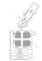
- FIG. 1 is a diagram showing the configuration of a position detection system 1 according to an embodiment of the present invention.
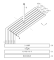
- 3 is a diagram illustrating a method of position detection by a sensor controller 31.
- FIG. It is a figure which shows the example of the amplitude of the received signal Rx detected in each loop coil LCx.
- 3 is a diagram showing internal circuits of a sensor controller 31 and an electromagnetic induction pen 2.
- FIG. 2 is a waveform diagram showing simulation results of signals related to the electromagnetic induction pen 2 and the loop coil LC near the coil L of the electromagnetic induction pen 2.
- FIG. 6 is a waveform diagram obtained by enlarging FIG. 5 in the time direction.
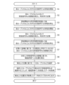
- FIG. 3 is a process flow diagram showing a process performed by the sensor controller 31 to derive the position of the electromagnetic induction pen 2 and to acquire data transmitted by the electromagnetic induction pen 2.
- FIG. 3 is a process flow diagram showing a process performed by the sensor controller 31 to derive the position of the electromagnetic induction pen 2 and to acquire data
- FIG. 1 is a diagram showing the configuration of a position detection system 1 according to a first embodiment of the present invention.
- the position detection system 1 includes an electromagnetic induction pen 2 and a position detection device 3, each of which is compatible with the EMR method.
- the electromagnetic induction pen 2 is a pen-shaped device including a core body 20, a pressure sensor 21, a side switch 22, a processing circuit 23, a coil L, a capacitor Cp, and a switch element SW. Coil L and capacitor Cp are connected in series, and switch element SW is connected in parallel with capacitor Cp.
- the position detection device 3 is a device including a plurality of loop coils LC, a switch section 30, a sensor controller 31, and a host processor 32.
- the plurality of loop coils LC include a plurality of loop coils LCx (first loop coils) arranged in the x direction (first direction) and a plurality of loop coils LCx (first loop coils) arranged in the y direction (second direction) orthogonal to the x direction.
- a plurality of loop coils LCy (second loop coils) arranged are included.
- a typical example of the position detecting device 3 is a tablet terminal or a notebook computer whose display screen also serves as a touch screen, but the position detecting device 3 may be configured with a digitizer or the like that does not have a display screen.
- the sensor controller 31 supplies an alternating current signal Tx (second alternating current signal) to each of the plurality of loop coils LCx, an alternating current signal i 1 (first alternating current signal) flows to each loop coil LCx, and an alternating magnetic field is generated from the touch surface. AM is sent out.
- the coil L enters this alternating magnetic field AM while the switch element SW is off, an electromotive force is generated in the coil L, and an alternating current signal (third AC signal) flows.
- the alternating current signal Tx is a signal having a constant amplitude. Therefore, from equation (1), it is understood that when the AC signal i 2 is generated, the amplitude of the AC signal i 1 decreases by that amount. Also, considering that the closer the distance between the loop coil LCx and the coil L is, the larger the mutual inductance M becomes, from equation (1), the shorter the distance between the loop coil LCx and the coil L, the more the AC signal i It is understood that the amount of decrease in the amplitude of 1 becomes large.
- the amplitude of the AC signal i1 detected in the loop coil LCx which is relatively close to the coil L, is the same as the amplitude of the AC signal i1 detected in the loop coil LCx, which is relatively far from the coil L. It is understood that the amplitude of the signal i1 is small compared to the amplitude of the signal i1 . These mean that the position of the coil L in the x direction can be determined from the amount of decrease in the amplitude of the AC signal i1 .
- the amplitude of the AC signal i1 generated in each loop coil LCx is detected, and based on the detected amplitude, the electromagnetic induction pen in the x direction is
- the sensor controller 31 is configured to detect the position of 2. The same applies to the y direction, and in this embodiment, the amplitude of the AC signal i1 generated in each loop coil LCy is detected when the AC signal Tx is supplied to each loop coil LCy, and the amplitude is calculated based on the detected amplitude.
- the sensor controller 31 is configured to detect the position of the electromagnetic induction pen 2 in the y direction.
- the electromagnetic induction pen 2 is controlled in the x direction (or y direction) by simultaneously supplying the AC signal Tx to each of the plurality of loop coils LCx (or the plurality of loop coils LCy). Since the position can be detected, the position of the electromagnetic induction pen 2 can be detected in a shorter time than with a conventional sensor controller that sequentially drives the loop coils LCx one by one while detecting the induced current appearing in each loop coil LCy. becomes possible.
- data is also transmitted from the electromagnetic induction pen 2 to the sensor controller 31 using the above principle. That is, when the switch element SW is on, the capacitor Cp is short-circuited, so that the resonant circuit is not formed in the electromagnetic induction pen 2. Then, the AC signal i 2 is not generated, and as a result, the amplitude of the AC signal i 1 is not decreased.
- the loop coil LCx near the coil L can be switched between a state in which the amplitude of the AC signal i1 decreases and a state in which it does not decrease by turning on and off the switch element SW.
- the electromagnetic induction pen 2 is configured to turn on and off the switch element SW according to the content of the data to be transmitted, and by demodulating the AC signal i1 in each loop coil LCx based on its amplitude.
- the sensor controller 31 is configured to acquire the data transmitted by the electromagnetic induction pen 2. According to these configurations, it becomes possible to transmit data from the electromagnetic induction pen 2 to the sensor controller 31 in parallel with the detection of the position of the electromagnetic induction pen 2 by the sensor controller 31.
- the core body 20 is a rod-shaped member that constitutes the pen tip of the electromagnetic induction pen 2, and is configured to be movable in the pen axis direction.
- the rear end of the core body 20 is in contact with the pressure sensor 21 .
- the pressure sensor 21 is a sensor that detects the pressure applied to the pen tip by detecting the pressing force from the rear end of the core body 20, and supplies a value indicating the detected pressure (pen pressure value) to the processing circuit 23. It is configured like this.
- the side switch 22 is an on/off type switch provided on the surface of the electromagnetic induction pen 2, and is configured to supply information indicating its on/off state (on/off information) to the processing circuit 23.
- FIG. 2 shows an example in which the electromagnetic induction pen 2 has one side switch 22, the electromagnetic induction pen 2 may have a plurality of side switches 22. Further, a similar switch may be provided on a surface other than the side surface of the electromagnetic induction pen 2 (for example, at the end).
- the coil L is an inductor provided near the pen tip and magnetically coupled to the loop coil LC in the position detection device 3.
- the coil L is connected in series with the capacitor Cp, and forms a resonant circuit together with the capacitor Cp.
- the inductance of the coil L and the capacitance of the capacitor Cp are set so that the resonant frequency of this resonant circuit is substantially equal to the frequency of the alternating current signal Tx.
- the switch element SW is a single-pole, single-throw switch connected in series to the capacitor Cp.
- the coil L and the capacitor Cp function as a resonant circuit when the switch element SW is off, but do not function as a resonant circuit when the switch element SW is on because the capacitor Cp is short-circuited. If the coil L and capacitor Cp do not function as a resonant circuit, the above-mentioned alternating current signal i2 will not be generated even if the coil L enters the alternating magnetic field AM.
- the processing circuit 23 is an integrated circuit that transmits data to the position detection device 3 by executing on/off control of the switch element SW based on the data transmitted to the position detection device 3.
- Examples of the data to be transmitted include the pen pressure value and on/off information described above, as well as a pen ID uniquely assigned to the electromagnetic induction pen 2.
- the processing circuit 23 turns off the switch element SW and performs an operation of detecting the alternating current signal i2 generated in the resonant circuit by the alternating magnetic field AM sent out by the position detection device 3.
- the data is stored for a predetermined period of time from the timing at which the AC signal i2 is generated (that is, the timing at which the sensor controller 31 starts supplying the AC signal Tx to the loop coil LC).
- the transmitter is configured to perform on/off control of the switch element SW for transmitting.
- the processing circuit 23 controls the switch element SW to turn on when transmitting data "0", and controls the switch element SW to turn off when transmitting data "1". This is nothing but on/off modulation of the AC signal i2 by on/off control of the switch element SW.
- the position detection device 3 receives the data transmitted by the processing circuit 23 by detecting this on-off modulation as the presence or absence of a decrease in the amplitude of the AC signal i1 .
- the plurality of loop coils LC are coils arranged within the touch surface, and are configured to include the plurality of loop coils LCx and LCy described above.
- One end of each loop coil LC is connected to the switch section 30, and the other end is grounded.
- the switch unit 30 is a circuit that serves to connect one or more of the plurality of loop coils LC to the sensor controller 31 under the control of the sensor controller 31.
- the sensor controller 31 has a function of detecting the position of the electromagnetic induction pen 2 within the touch surface, acquiring data transmitted by the electromagnetic induction pen 2, and sequentially supplying the detected position and the acquired data to the host processor 32. It is an integrated circuit. In order to perform these processes, the sensor controller 31 simultaneously supplies the AC signal Tx to the plurality of loop coils LCx, and performs a process of detecting the amplitude of the AC signal i1 generated in each loop coil LCx at that time. Further, the sensor controller 31 simultaneously supplies the AC signal Tx to the plurality of loop coils LCy, and performs a process of detecting the amplitude of the AC signal i1 generated in each loop coil LC at that time.
- FIG. 2 is a diagram showing the internal circuit of the sensor controller 31.
- the figure also illustrates one of the plurality of loop coils LC provided in the position detection device 3 and a circuit (the same as that shown in FIG. 1) in the electromagnetic induction pen 2.
- the sensor controller 31 includes a circuit shown in the figure for each loop coil LC.
- the sensor controller 31 includes a signal source 40 that generates an alternating current signal Tx that vibrates at a constant frequency and amplitude, a high-pass filter 41, and a capacitor Cs that forms a resonant circuit together with a loop coil LC.
- the pressure circuit 42 is configured to include a pressure circuit 42.
- the alternating current signal Tx generated by the signal source 40 has low frequency noise removed by a high-pass filter 41, and then is supplied to a resonant circuit constituted by a loop coil LC and a capacitor Cs.
- the illustrated alternating current signal i 1 is then generated in the resonant circuit, resulting in the illustrated alternating magnetic field AM.
- the voltage dividing circuit 42 is connected between a ground terminal and a resonant circuit constituted by a loop coil LC and a capacitor Cs, and its output signal reflects the amplitude of the alternating current signal i1 .
- the sensor controller 31 thus detects the output signal of the voltage dividing circuit 42 reflecting the amplitude of the AC signal i1 as the received signal Rx. Note that the voltage dividing circuit 42 is used to adjust the amplitude of the received signal Rx in accordance with the dynamic range of a subsequent stage circuit (not shown).
- the amplitude of the AC signal i 1 when the coil L of the electromagnetic induction pen 2 exists near the loop coil LC and the AC signal i 2 is flowing there, the amplitude of the AC signal i 1 is , the amplitude is smaller than the amplitude when the coil L of the electromagnetic induction pen 2 does not exist near the loop coil LC, or when the AC signal i 2 does not flow there even if it exists.
- the sensor controller 31 detects the amplitude of the AC signal i1 by detecting the amplitude of the received signal Rx in a subsequent circuit (not shown), and based on the result, detects the position of the electromagnetic induction pen 2 and detects the amplitude of the electromagnetic induction pen 2. It is configured to demodulate the data transmitted by the pen 2.
- the frequency of the alternating current signal Tx is often set to 666 kHz, but in this embodiment, it is preferable that the frequency of the alternating current signal Tx is set to a value higher than 666 kHz. In a typical example, the frequency of the alternating current signal Tx is set to 13.56 MHz.
- the reason for setting the frequency of the AC signal Tx to a high value in this way is that the higher the frequency of the AC signal Tx, the greater the amplitude change of the AC signal i 1 due to the presence or absence of the AC signal i 2 , and the amplitude change in the sensor controller 31. This is because the detection accuracy increases.
- FIG. 3 is a diagram illustrating a method of detecting the position of the electromagnetic induction pen 2 using detection of the amplitude of the received signal Rx.
- the figure shows a case where the position of the electromagnetic induction pen 2 in the x direction is detected.
- the figure also shows a case where the coil L of the electromagnetic induction pen 2 is present above the loop coil LCx n among the plurality of loop coils LCx including the seven loop coils LCx n-3 to LCx n+3 shown.
- the sensor controller 31 first supplies an AC signal Tx to each loop coil LCx, and at the same time detects a received signal Rx in each loop coil LCx n .
- FIG. 4 is a diagram showing the amplitude of the received signal Rx detected in each loop coil LCx shown in FIG. 3.
- the amplitude of the received signal Rx is smallest at the loop coil LCx n closest to the coil L, and becomes smaller as it moves away from the loop coil LCx n .
- the sensor controller 31 detects the amplitude of the received signal Rx in each loop coil LCx, the sensor controller 31 approximates the value using a predetermined approximate curve, and derives the position in the x direction corresponding to the apex thereof. Then, the derived position is detected as the position of the electromagnetic induction pen 2 in the x direction. The same applies to the position in the y direction.
- FIG. 5 is a waveform diagram showing the simulation results of each signal related to the electromagnetic induction pen 2 and the loop coil LC located near the coil L of the electromagnetic induction pen 2. The figure shows the waveforms of each signal when the switch element SW of the electromagnetic induction pen 2 is turned on and off at regular intervals.
- FIG. 6 is a waveform diagram obtained by enlarging FIG. 5 in the time direction.
- FIG. 5A shows a simulation result of the SW control signal generated within the processing circuit 23 to control the switch element SW.
- the processing circuit 23 turns on the switch element SW when the value of the SW control signal changes from a value smaller than 0 to a value larger than 0, and when the value of the SW control signal changes from a value larger than 0 to a value smaller than 0.
- the switch element SW is sometimes turned off.
- 5(b), (c), and (d) show the simulation results of the voltage V L (voltage between both ends of the coil L), the received signal Rx, and the AC signal Tx shown in FIG. 2, respectively.
- the switch element SW when the switch element SW is off, a voltage VL is generated, resulting in the generation of the AC signal i2 shown in FIG. 2, while the switch element SW is on. In this case, the voltage VL is not generated and the AC signal i2 shown in FIG. 2 does not flow.
- the amplitude of the received signal Rx is smaller than when the voltage V L is not generated.
- the sensor controller 31 modulates the received signal Rx that changes in this way using a modulation method similar to on-off modulation (for example, a method that assigns "0" when the amplitude is relatively large and "1" when the amplitude is relatively small). ) to obtain the data transmitted by the electromagnetic induction pen 2 using on/off modulation by turning on/off the switch element SW.
- FIG. 7 is a process flow diagram showing the process performed by the sensor controller 31 to derive the position of the electromagnetic induction pen 2 and to acquire the data transmitted by the electromagnetic induction pen 2.
- the sensor controller 31 is configured to periodically execute the process shown in the figure.
- the sensor controller 31 first starts supplying the AC signal Tx to each loop coil LCx (step S1), and while supplying the AC signal Tx, detects the amplitude of the received signal Rx in each loop coil LCx. and stored in chronological order (step S2). Specifically, the received signal Rx may be sampled at a predetermined sampling frequency, and a series of digital values obtained as a result of sampling may be stored. After a predetermined period of time has passed since the start of supply in step S1, the sensor controller 31 stops supplying the AC signal Tx to each loop coil LCx (step S3). The sensor controller 31 then performs similar processing regarding the loop coil LCy (steps S4 to S6).
- the sensor controller 31 determines the amplitude of the received signal Rx in each loop coil LC when the AC signal i2 is flowing, based on the series of stored amplitudes (step S7). That is, when the electromagnetic induction pen 2 transmits data by turning on and off the switch element SW, the amplitude of the received signal Rx fluctuates between relatively large and small amplitudes, as shown in FIG. 5(c). It turns out. In this case, since the period during which the amplitude of the received signal Rx is relatively small corresponds to the period during which the AC signal i 2 is flowing, the sensor controller 31 adjusts the amplitude of this period to the period during which the AC signal i 2 is flowing.
- the stored amplitude (amplitude that is a constant value) may be determined as the amplitude of the received signal Rx in each loop coil LC when the AC signal i2 is flowing.
- the sensor controller 31 derives the position of the electromagnetic induction pen 2 based on the amplitude of the received signal Rx determined in step S7 (step S8). Specifically, the sensor controller 31 approximates the amplitude of the received signal Rx in each loop coil LCx by a predetermined approximate curve, derives the position corresponding to the apex as the position of the electromagnetic induction pen 2 in the x direction, and The amplitude of the received signal Rx in each loop coil LCy may be approximated by a predetermined approximate curve, and the position corresponding to the apex thereof may be derived as the position of the electromagnetic induction pen 2 in the y direction.
- the sensor controller 31 selects one loop coil LC based on the position derived in step S9 (step S9). Specifically, the loop coil LCx closest to the x-direction position derived in step S9 (or the loop coil LCy closest to the y-direction position derived in step S9) may be selected. Then, the sensor controller 31 demodulates the received signal Rx detected by the selected loop coil LC (the signal indicated by the series of amplitudes stored in step S2 or step S5), thereby converting the data transmitted by the electromagnetic induction pen 2. Acquire (step S10). In a specific example, the sensor controller 31 may demodulate the received signal Rx by assigning "0" when the amplitude of the received signal Rx is relatively large and "1" when the amplitude is relatively small. .
- the sensor controller 31 outputs the position derived in step S9 and the data acquired in step S9 to the host processor 32, and ends the series of processing (step S11).
- the position of the electromagnetic induction pen 2 can be detected without sequentially driving the loop coils LCx one by one. It becomes possible to transmit data from the guiding pen 2 to the sensor controller 31.
- the host processor 32 uses the position and data supplied from the sensor controller 31 to perform processing such as moving the cursor displayed on the display surface and generating stroke data indicating the trajectory of the electromagnetic induction pen 2 within the touch surface. conduct. Regarding the stroke data, the host processor 32 performs a process of rendering and displaying the generated stroke data, a process of generating and recording digital ink including the generated stroke data, and a process of generating and recording the generated digital ink according to user instructions. It also performs processing such as sending the data to an external device.
- the position of the electromagnetic induction pen 2 in the x direction can be detected by simultaneously supplying the AC signal Tx to each of the plurality of loop coils LCx. Can be done. The same applies to the y direction. Therefore, the position of the electromagnetic induction pen 2 can be detected in a shorter time than the conventional method of sequentially driving the loop coils LCx one by one while detecting the induced current appearing in each loop coil LCy.
- the electromagnetic induction pen 2 transmits data using on/off modulation by turning on and off the switch element SW, and the sensor controller 31 demodulates the change in the amplitude of the received signal Rx. In parallel with position detection, data can be transmitted from the electromagnetic induction pen 2 to the sensor controller 31.
- Position detection system Electromagnetic induction pen 3 Position detection device 20 Core body 21 Pressure sensor 22 Side switch 23 Processing circuit 30 Switch unit 31 Sensor controller 32 Host processor 40 Signal source 41 High-pass filter 42 Voltage dividing circuit L Coil Cp, Cs Capacitor LC , LCx, LCy Loop coil SW Switch element
Landscapes
- Engineering & Computer Science (AREA)
- General Engineering & Computer Science (AREA)
- Theoretical Computer Science (AREA)
- Physics & Mathematics (AREA)
- General Physics & Mathematics (AREA)
- Human Computer Interaction (AREA)
- Electromagnetism (AREA)
- Position Input By Displaying (AREA)
- Measurement Of Length, Angles, Or The Like Using Electric Or Magnetic Means (AREA)
Abstract
Description

2 電磁誘導ペン
3 位置検出装置
20 芯体
21 圧力センサ
22 サイドスイッチ
23 処理回路
30 スイッチ部
31 センサコントローラ
32 ホストプロセッサ
40 信号源
41 ハイパスフィルタ
42 分圧回路
L コイル
Cp,Cs コンデンサ
LC,LCx,LCy ループコイル
SW スイッチ素子
Claims (14)
- 第1の方向に並べて配置される複数の第1のループコイルと、
前記複数の第1のループコイルそれぞれに生じる第1の交流信号の振幅を前記複数の第1のループコイルのそれぞれに第2の交流信号を供給しながら検出し、
前記複数の第1のループコイルのそれぞれにおいて検出された前記振幅に基づいて、前記第1の方向における電磁誘導ペンの位置を検出するセンサコントローラと、を含む、
位置検出装置。 - 前記電磁誘導ペン内のコイルとの距離が相対的に近い前記第1のループコイルにおいて検出される前記振幅は、前記電磁誘導ペン内のコイルとの距離が相対的に遠い前記第1のループコイルにおいて検出される前記振幅に比べて小さい、
請求項1に記載の位置検出装置。 - 前記センサコントローラは信号源を有し、
前記第2の交流信号は、前記信号源から前記複数の第1のループコイルのそれぞれに供給される信号である、
請求項1に記載の位置検出装置。 - 前記第1の方向と直交する第2の方向に並べて配置される複数の第2のループコイルをさらに備え、
前記センサコントローラは、
前記複数の第2のループコイルそれぞれに生じる前記第1の交流信号の振幅を前記複数の第2のループコイルのそれぞれに前記第2の交流信号を供給しながら検出し、
前記複数の第2のループコイルのそれぞれにおいて検出された前記振幅に基づいて、前記第2の方向における前記電磁誘導ペンの位置を検出する、
請求項1に記載の位置検出装置。 - 前記センサコントローラは、
検出した前記第1の方向における電磁誘導ペンの位置に基づいて前記複数の第1のループコイルのうちの1つを選択し、
選択した前記第1のループコイルに生じる前記第1の交流信号を復調することにより、前記電磁誘導ペンが送信したデータを取得する、
請求項1に記載の位置検出装置。 - 前記センサコントローラは、
検出した前記複数の第1のループコイルそれぞれに生じる第1の交流信号の振幅を時系列で記憶し、
記憶した一連の前記振幅に基づき、前記電磁誘導ペン内の共振回路に第3の交流信号が生じているときの前記複数の第1のループコイルそれぞれにおける前記第1の交流信号の振幅を決定し、
決定した前記複数の第1のループコイルそれぞれにおける前記第1の交流信号の振幅に基づいて、前記第1の方向における電磁誘導ペンの位置を検出する、
請求項1に記載の位置検出装置。 - 前記複数の第1のループコイルのそれぞれに接続された分圧回路を含み、
前記センサコントローラは、前記分圧回路の出力信号の振幅を検出することにより、対応する前記第1のループコイルに生じる前記第1の交流信号の振幅を検出する、
請求項1に記載の位置検出装置。 - 電磁誘導ペン及び位置検出装置を含む位置検出システムであって、
前記電磁誘導ペンは、コイル及びコンデンサを含む共振回路を含み、
前記位置検出装置は、
第1の方向に並べて配置される複数の第1のループコイルと、
前記複数の第1のループコイルそれぞれに生じる第1の交流信号の振幅を前記複数の第1のループコイルのそれぞれに第2の交流信号を供給しながら検出し、
前記複数の第1のループコイルのそれぞれにおいて検出された前記振幅に基づいて、前記第1の方向における前記電磁誘導ペンの位置を検出するセンサコントローラと、を含む、
位置検出システム。 - 前記共振回路は、前記第1の交流信号の周波数と実質的に等しい周波数を共振周波数とするものであり、
前記電磁誘導ペン内のコイルとの距離が相対的に近い前記第1のループコイルにおいて検出される前記振幅は、前記電磁誘導ペン内のコイルとの距離が相対的に遠い前記第1のループコイルにおいて検出される前記振幅に比べて小さい、
請求項8に記載の位置検出システム。 - 前記位置検出装置は、前記第1の方向と直交する第2の方向に並べて配置される複数の第2のループコイルをさらに備え、
前記センサコントローラは、
前記複数の第2のループコイルそれぞれに生じる前記第1の交流信号の振幅を前記複数の第2のループコイルのそれぞれに前記第2の交流信号を流しながら検出し、
前記複数の第2のループコイルのそれぞれにおいて検出された前記振幅に基づいて、前記第2の方向における前記電磁誘導ペンの位置を検出する、
請求項8に記載の位置検出システム。 - 前記電磁誘導ペンは、
前記コンデンサと並列に接続されたスイッチ素子と、
位置検出装置に対して送信するデータに基づいて前記スイッチ素子のオンオフ制御を実行することにより、前記位置検出装置に対して前記データを送信する処理回路と、を含み、
前記センサコントローラは、
検出した前記第1の方向における電磁誘導ペンの位置に基づいて前記複数の第1のループコイルのうちの1つを選択し、
選択した前記第1のループコイルに生じる前記第1の交流信号を復調することにより、前記電磁誘導ペンが送信した前記データを取得する、
請求項8に記載の位置検出システム。 - 前記処理回路は、前記共振回路内に発生する第3の交流信号の検出動作を行い、前記第3の交流信号の発生したタイミングから所定時間にわたり、前記データを送信するための前記スイッチ素子のオンオフ制御を実行する、
請求項11に記載の位置検出システム。 - 前記センサコントローラは、
検出した前記複数の第1のループコイルそれぞれに生じる第1の交流信号の振幅を時系列で記憶し、
記憶した一連の前記振幅に基づき、前記共振回路に第3の交流信号が生じているときの前記複数の第1のループコイルそれぞれにおける前記第1の交流信号の振幅を決定し、
決定した前記複数の第1のループコイルそれぞれにおける前記第1の交流信号の振幅に基づいて、前記第1の方向における電磁誘導ペンの位置を検出する、
請求項8に記載の位置検出システム。 - 前記センサコントローラは、
前記複数の第1のループコイルのそれぞれに接続された分圧回路を含み、
前記分圧回路の出力信号の振幅を検出することにより、対応する前記第1のループコイルに生じる前記第1の交流信号の振幅を検出する、
請求項8に記載の位置検出システム。
Priority Applications (5)
| Application Number | Priority Date | Filing Date | Title |
|---|---|---|---|
| JP2024534980A JPWO2024018809A1 (ja) | 2022-07-22 | 2023-06-21 | |
| DE112023001932.0T DE112023001932T5 (de) | 2022-07-22 | 2023-06-21 | Positionsdetektionsvorrichtung und positionsdetektionssystem |
| CN202380035778.3A CN119013649A (zh) | 2022-07-22 | 2023-06-21 | 位置检测装置及位置检测系统 |
| KR1020247040588A KR20250038643A (ko) | 2022-07-22 | 2023-06-21 | 위치 검출 장치 및 위치 검출 시스템 |
| US19/011,287 US20250138690A1 (en) | 2022-07-22 | 2025-01-06 | Position detection device and position detection system |
Applications Claiming Priority (2)
| Application Number | Priority Date | Filing Date | Title |
|---|---|---|---|
| JP2022116824 | 2022-07-22 | ||
| JP2022-116824 | 2022-07-22 |
Related Child Applications (1)
| Application Number | Title | Priority Date | Filing Date |
|---|---|---|---|
| US19/011,287 Continuation US20250138690A1 (en) | 2022-07-22 | 2025-01-06 | Position detection device and position detection system |
Publications (1)
| Publication Number | Publication Date |
|---|---|
| WO2024018809A1 true WO2024018809A1 (ja) | 2024-01-25 |
Family
ID=89617589
Family Applications (1)
| Application Number | Title | Priority Date | Filing Date |
|---|---|---|---|
| PCT/JP2023/022981 Ceased WO2024018809A1 (ja) | 2022-07-22 | 2023-06-21 | 位置検出装置及び位置検出システム |
Country Status (6)
| Country | Link |
|---|---|
| US (1) | US20250138690A1 (ja) |
| JP (1) | JPWO2024018809A1 (ja) |
| KR (1) | KR20250038643A (ja) |
| CN (1) | CN119013649A (ja) |
| DE (1) | DE112023001932T5 (ja) |
| WO (1) | WO2024018809A1 (ja) |
Cited By (1)
| Publication number | Priority date | Publication date | Assignee | Title |
|---|---|---|---|---|
| CN119520238A (zh) * | 2024-11-13 | 2025-02-25 | 新华三技术有限公司 | 通信系统 |
Citations (2)
| Publication number | Priority date | Publication date | Assignee | Title |
|---|---|---|---|---|
| JPS63307522A (ja) * | 1987-06-08 | 1988-12-15 | Wacom Co Ltd | 位置検出装置 |
| WO2016121045A1 (ja) * | 2015-01-29 | 2016-08-04 | 株式会社ワコム | 静電ペン |
Family Cites Families (1)
| Publication number | Priority date | Publication date | Assignee | Title |
|---|---|---|---|---|
| JPH0519164A (ja) | 1990-11-28 | 1993-01-29 | Canon Inc | ズームレンズ |
-
2023
- 2023-06-21 DE DE112023001932.0T patent/DE112023001932T5/de not_active Withdrawn
- 2023-06-21 KR KR1020247040588A patent/KR20250038643A/ko active Pending
- 2023-06-21 JP JP2024534980A patent/JPWO2024018809A1/ja active Pending
- 2023-06-21 CN CN202380035778.3A patent/CN119013649A/zh active Pending
- 2023-06-21 WO PCT/JP2023/022981 patent/WO2024018809A1/ja not_active Ceased
-
2025
- 2025-01-06 US US19/011,287 patent/US20250138690A1/en active Pending
Patent Citations (2)
| Publication number | Priority date | Publication date | Assignee | Title |
|---|---|---|---|---|
| JPS63307522A (ja) * | 1987-06-08 | 1988-12-15 | Wacom Co Ltd | 位置検出装置 |
| WO2016121045A1 (ja) * | 2015-01-29 | 2016-08-04 | 株式会社ワコム | 静電ペン |
Cited By (1)
| Publication number | Priority date | Publication date | Assignee | Title |
|---|---|---|---|---|
| CN119520238A (zh) * | 2024-11-13 | 2025-02-25 | 新华三技术有限公司 | 通信系统 |
Also Published As
| Publication number | Publication date |
|---|---|
| KR20250038643A (ko) | 2025-03-19 |
| US20250138690A1 (en) | 2025-05-01 |
| CN119013649A (zh) | 2024-11-22 |
| JPWO2024018809A1 (ja) | 2024-01-25 |
| DE112023001932T5 (de) | 2025-02-27 |
Similar Documents
| Publication | Publication Date | Title |
|---|---|---|
| US4999461A (en) | Coordinates input apparatus | |
| US7176907B2 (en) | Device and method for pointer system of digitizer tablet | |
| US9158393B2 (en) | Active stylus for touch sensing applications | |
| KR101830981B1 (ko) | 전자기 유도 방식에 기초하여 터치 오브젝트의 위치를 측정하는 센싱 장치 및 그 제어 방법 | |
| CN104199587A (zh) | 电感触摸屏及其驱动检测方法、坐标输入装置 | |
| EP1413975B1 (en) | Device and method for an electromagnetic digitizer tablet | |
| US20250138690A1 (en) | Position detection device and position detection system | |
| US10254862B2 (en) | Stylus and touch control method | |
| US20250258566A1 (en) | Position detection apparatus configured to detect the positions of multiple position indicators, and position detection method | |
| KR20150008624A (ko) | 전자 기기 제어 방법 및 장치 | |
| CN118843850A (zh) | 位置检测装置、电磁感应笔及位置检测系统 | |
| WO2013067810A1 (zh) | 位置指示装置及方法 | |
| JPS63279315A (ja) | 位置検出装置 | |
| US20250362779A1 (en) | Method carried out by sensor controller and sensor controller | |
| KR20140141942A (ko) | 입력 시스템의 터치 검출 방법 및 이를 위한 터치 제어부 | |
| CN115461703B (zh) | 触摸装置及其触摸检测方法 | |
| JP2837858B2 (ja) | 座標入力装置 | |
| WO2023223587A1 (ja) | 電磁誘導ペン及び位置検出装置 | |
| JPH03241415A (ja) | 座標入力装置 | |
| JPH0756674A (ja) | 座標読取装置 | |
| JPH0667790A (ja) | 座標入力装置 | |
| JPH0756676A (ja) | 座標読取装置 | |
| JPH0253128A (ja) | 位置検出装置 |
Legal Events
| Date | Code | Title | Description |
|---|---|---|---|
| 121 | Ep: the epo has been informed by wipo that ep was designated in this application |
Ref document number: 23842740 Country of ref document: EP Kind code of ref document: A1 |
|
| ENP | Entry into the national phase |
Ref document number: 2024534980 Country of ref document: JP Kind code of ref document: A |
|
| WWE | Wipo information: entry into national phase |
Ref document number: 202380035778.3 Country of ref document: CN |
|
| WWE | Wipo information: entry into national phase |
Ref document number: 112023001932 Country of ref document: DE |
|
| WWP | Wipo information: published in national office |
Ref document number: 112023001932 Country of ref document: DE |
|
| WWP | Wipo information: published in national office |
Ref document number: 1020247040588 Country of ref document: KR |
|
| 122 | Ep: pct application non-entry in european phase |
Ref document number: 23842740 Country of ref document: EP Kind code of ref document: A1 |