WO2024018573A1 - 温湿度制御装置、及び、温湿度制御装置と調湿ガス発生装置との組合せ - Google Patents
温湿度制御装置、及び、温湿度制御装置と調湿ガス発生装置との組合せ Download PDFInfo
- Publication number
- WO2024018573A1 WO2024018573A1 PCT/JP2022/028266 JP2022028266W WO2024018573A1 WO 2024018573 A1 WO2024018573 A1 WO 2024018573A1 JP 2022028266 W JP2022028266 W JP 2022028266W WO 2024018573 A1 WO2024018573 A1 WO 2024018573A1
- Authority
- WO
- WIPO (PCT)
- Prior art keywords
- gas
- water tank
- temperature
- humidity control
- container
- Prior art date
- Legal status (The legal status is an assumption and is not a legal conclusion. Google has not performed a legal analysis and makes no representation as to the accuracy of the status listed.)
- Ceased
Links
Images




Classifications
-
- G—PHYSICS
- G01—MEASURING; TESTING
- G01N—INVESTIGATING OR ANALYSING MATERIALS BY DETERMINING THEIR CHEMICAL OR PHYSICAL PROPERTIES
- G01N35/00—Automatic analysis not limited to methods or materials provided for in any single one of groups G01N1/00 - G01N33/00; Handling materials therefor
-
- H—ELECTRICITY
- H10—SEMICONDUCTOR DEVICES; ELECTRIC SOLID-STATE DEVICES NOT OTHERWISE PROVIDED FOR
- H10P—GENERIC PROCESSES OR APPARATUS FOR THE MANUFACTURE OR TREATMENT OF DEVICES COVERED BY CLASS H10
- H10P95/00—Generic processes or apparatus for manufacture or treatments not covered by the other groups of this subclass
Definitions
- the present invention relates to a temperature/humidity control device and a combination of the temperature/humidity control device and a humidity control gas generating device.
- Patent Document 1 discloses a thermomechanical analysis device for a humid atmosphere. According to that disclosure, a heat retention chamber is formed inside a thermostatic jacket in which a heat medium at a predetermined temperature circulates. The air supply pipe and the exhaust pipe leading to the air supply port and the exhaust port of the heat retention chamber each pass through the constant temperature jacket.
- An object of the present invention is to provide a temperature and humidity control device that can control the temperature and humidity within a chamber with high precision, and a combination of the temperature and humidity control device and a humidity control gas generator.
- a temperature and humidity control device has a container defining a chamber, a bottom wall, a top wall, and a side wall surrounding the container, and the container is spaced apart from the bottom wall, the top wall, and the side wall.
- a water tank configured to accommodate a heat medium liquid in the space between the container and the bottom wall, top wall, and side wall so that the entire outer surface of the container can be submerged, and to control the temperature of the heat medium liquid in the water tank.
- a temperature control device for supplying a heat medium liquid whose temperature is controlled by the temperature control device into a water tank, and a circulation device for circulating the heat medium liquid so as to return the heat medium liquid in the water tank to the temperature control device; , a gas introduction pipe having a gas outlet open into the chamber and introducing a humidity control gas whose humidity has been adjusted to a predetermined value into the chamber of the container.
- the inner tank further includes an inner tank disposed within the tank and accommodating the container, the inner tank having a bottom plate, a side plate, and an upper opening, the container being spaced apart from the bottom plate and the side plate, and the inner tank having a space inside the inner tank. It is divided into an inner space inside the inner water tank and an outer space outside the inner water tank, and the heat transfer liquid supplied in the water tank is configured to flow from the inner space to the outer space through the upper opening of the inner water tank.
- the supply port for the heat transfer liquid from the circulation device may be arranged at the bottom of the inner space within the inner water tank, and the outlet for the heat transfer liquid from the water tank may be arranged at the bottom of the outer space within the water tank.
- the gas introduction pipe extends from the container through the space to the outside of the water tank, and the part of the gas introduction pipe that exists in the space is used for heat exchange between the humidity control gas flowing inside the part and the heat transfer liquid in the space.
- a heat exchanger may be formed for this purpose.
- the inner water tank has a circular, rectangular, or elliptical shape in plan view, and a plurality of supply ports for the heat medium liquid from the circulation device are arranged at the bottom of the inner space in the inner water tank, and the plurality of supply ports have a shape in plan view. It may be arranged at a position symmetrical to the center of the inner aquarium.
- the capacity of the container may be 500 mL or more, preferably 1.0 L, and more preferably 5.0 L or more.
- a combination of a temperature and humidity control device and a humidity control gas generation device includes the above temperature and humidity control device and a humidity control gas generation device that supplies humidity control gas to the above temperature and humidity control device.
- the humidity control gas generator includes a saturation tank main body that includes a gas region and a storage area below the gas region, and a gas recirculation device disposed inside the saturation tank main body.
- the gas reflux device includes a gas return pipe, a gas delivery pipe, a drain pipe, and a trap box.
- a gas return pipe passes from a gas inlet located within the gas field through the reservoir area to a gas outlet located within the trap box.
- the gas delivery pipe extends from a gas delivery port located inside the trap box to a gas delivery port located outside the saturation tank body.
- a drain pipe runs from a water inlet located within the trap box to a water outlet located outside the saturation tank body.
- the present invention can provide a temperature and humidity control device that can control the temperature and humidity within a chamber with high precision, and a combination of the temperature and humidity control device and a humidity control gas generation device.
- FIG. 1 is a diagram of a combination of a temperature and humidity control device and a humidity control gas generation device according to an embodiment, mainly showing a longitudinal cross-sectional view of the temperature and humidity control device.
- FIG. 1 is a longitudinal cross-sectional view of a humidity control gas generator according to an embodiment.
- FIG. 2 is an enlarged vertical cross-sectional view of a flange portion of a humidity control gas generator according to an embodiment. It is a cross-sectional view of a gas recirculation device of a humidity control gas generator concerning one embodiment. It is a figure which shows the modification of the humidity control gas generator of FIG.
- FIG. 1 is a diagram of a combination of a temperature/humidity control device 1 and a humidity control gas generating device 101 according to an embodiment, and mainly shows a longitudinal cross-sectional view of the temperature/humidity control device 1.
- the humidity control gas generator 101 is a device that generates gas whose humidity is adjusted to a predetermined value, and supplies the gas to the temperature and humidity control device 1 .
- the temperature and humidity control device 1 includes a device main body 10 and a temperature control/circulation device 5.
- the device main body 10 includes a container 2, a water tank 3, an inner water tank 4, and a gas introduction pipe 6.
- the container 2 has an approximately cylindrical or polygonal cylinder (eg, square cylinder) shape as a whole.
- the container 2 has a container body 21 and a lid part 22.
- a chamber C is defined inside the container 2 by covering the upper opening of the container body 21 with the lid portion 22 .
- the lid part 22 is tightly fixed to the container body 21, liquid is prevented from entering the chamber C.
- a plurality of samples 23 are installed inside the chamber C.
- the capacity of the container 2 is, for example, 500 mL or more, preferably 1.0 L, and more preferably 5.0 L or more.
- the main material of the parts constituting the container 2 is a highly durable metal such as stainless steel. Note that the capacity of the container 2 is not limited to the above-mentioned capacity, and may be less than 500 mL.
- the water tank 3 has an approximately cylindrical or polygonal cylinder (eg, square cylinder) shape as a whole.
- the water tank 3 has a bottom wall 31, a top wall 32, and a side wall 33.
- a bottom wall 31, a top wall 32, and a side wall 33 surround the container 2.
- the container 2 is spaced apart from the bottom wall 31, the top wall 32, and the side walls 33.
- a heat medium liquid such as water or a coolant aqueous solution is poured into the space S between the container 2, the bottom wall 31, the top wall 32, and the side wall 33, leaving an atmospheric space above. is filled.
- the entire outer surface of the container 2 is submerged by the heat transfer liquid. Therefore, the temperature and humidity of the gas in the chamber C can be controlled with high precision.
- the main material of the parts constituting the water tank 3 is a highly durable metal such as stainless steel.
- the inner water tank 4 has an approximately cylindrical or polygonal cylinder (for example, square cylinder) shape as a whole.
- the inner water tank 4 is arranged within the water tank 3 and accommodates the container 2.
- the inner water tank 4 has a bottom plate 41, side plates 42, and an upper opening 43.
- the bottom plate 41 and the side plates 42 are arranged at intervals from the bottom wall 31 and the side walls 33, respectively.
- the container 2 is arranged at a distance from the bottom plate 41 and the side plates 42.
- the inner water tank 4 divides the space S into an inner space S1 located inside the inner water tank 4 and an outer space S2 located outside the inner water tank 4.
- the heat medium liquid supplied into the water tank 3 flows from the inner space S1 to the outer space S2 through the upper opening 43 of the inner water tank 4.
- the entire outer surface of the container 2 is submerged in the heat transfer liquid. Therefore, when the temperature and humidity control device 1 is in operation, the container 2 is covered by the inner jacket of the heat transfer liquid and the outer jacket of the heat transfer liquid. Therefore, heat exchange between the container 2 and the heat medium liquid is promoted, and the temperature and humidity of the gas in the chamber C can be controlled with higher precision.
- the temperature control/circulation device 5 is provided outside the device main body 10.
- the temperature control/circulation device 5 has a temperature control device and a circulation device.
- the temperature control device has a heating means and a cooling means, and can control the thermal refrigerant within a range of, for example, 5 to 55°C.
- the circulation device has a pump, and is configured to supply the heat medium liquid at a desired temperature controlled by the temperature control section into the water tank 3, and return the heat medium liquid in the water tank 3 to the temperature control/circulation device 5. to circulate the heat transfer fluid.
- the temperature control/circulation device 5, the water tank 3, and the inner water tank 4 are connected by a liquid supply pipe 51 and a liquid return pipe 52.
- the liquid supply pipe 51 and the liquid return pipe 52 are provided within the apparatus main body 10.
- the liquid supply pipe 51 branches into a plurality of parts in the middle, and each branch pipe 53 is provided with a flow meter 54.
- the amount of heat medium liquid flowing through each branch pipe 53 is controlled to be equal based on the measurement results of each flow meter 54.
- the inner water tank 4 has a circular, rectangular, or elliptical shape in plan view.
- the plurality of supply ports 55 are arranged at symmetrical positions with respect to the center of the inner water tank 4 in plan view. Thereby, the heat medium liquid can be uniformly flowed around the outer periphery of the container 2, and the accuracy of temperature control can be improved.
- there are two supply ports 55 but there may be three or more supply ports 55, and the number of branch pipes 53 increases as the number of supply ports 55 increases.
- the gas introduction pipe 6 extends from the container 2 to the outside of the water tank 3 through the space S (inner space S1 and outer space S2).
- An intermediate portion 61 of the gas introduction pipe 6 existing in the outer space S2 is not linear but has a spiral shape.
- the intermediate portion 61 functions as a heat exchanger. Therefore, the temperature of the gas passing through the intermediate portion 61 approaches the desired temperature, which further improves the accuracy of temperature control.
- a flexible hose 62 is connected to the end of the gas introduction pipe 6 outside the water tank 3.
- a heater (not shown) is provided around the flexible hose 62. The heater is provided to prevent the humidity control gas flowing through the flexible hose 62 from condensing.
- the end of the flexible hose 62 opposite to the gas introduction pipe 6 is connected to the humidity control gas generator 101 .
- the flexible hose 62 is connected to a gas delivery pipe 141 of a gas recirculation device 104, which will be described later (see FIG. 2).
- the humidity control gas from the humidity control gas generator 101 whose humidity has been adjusted to a predetermined value enters the chamber C through the gas outlet 63 that opens the gas introduction pipe 6 into the chamber C. be introduced.
- a plurality of ducts 7 are provided in the lid portion 22 of the container 2.
- the plurality of ducts 7 extend upward from the lid 22, penetrate the water tank 3, and extend to the outside of the water tank 3.
- the plurality of ducts 7 are ducts for inserting a sensor into the chamber C and for exhausting gas from the chamber C.
- a temperature sensor 71, a humidity sensor 72, and a displacement meter/load cell 73 are inserted into the chamber C via the plurality of ducts 7.
- Temperature sensor 71 measures the temperature inside chamber C.
- Humidity sensor 72 measures the humidity within chamber C. Detection signals from the temperature sensor 71 and the humidity sensor 72 are input to a control device (not shown) and are used for temperature control of the heat medium liquid by the temperature control/circulation device 5.
- the displacement meter/load cell 73 measures the load applied to the sample 23 placed in the chamber C and the displacement of the sample 23.
- An environmental temperature sensor 74 is provided outside the water tank 3 to monitor the environmental temperature within the
- the temperature and humidity control device 1 further includes a liquid level adjustment device 8.
- the liquid level adjustment device 8 includes a liquid storage container 81 , a supply pipe 82 , a discharge pipe 83 , two pumps 84 and 85 , a check valve 86 , and a valve 87 .
- the capacity of the liquid storage container 81 is, for example, 20L.
- the supply pipe 82 extends from the inner water tank 4 through the outer space S2 to the outside of the water tank 3, and extends to the lower part of the liquid storage container 81.
- the discharge pipe 83 extends from the inner water tank 4 through the outer space S2 to the outside of the water tank 3, and extends to the upper part of the liquid storage container 81.
- the supply pipe 82 is provided with a pump 84 and a check valve 86.
- the discharge pipe 83 is provided with a pump 85 and a valve 87.
- the liquid storage container 81 is provided with an air supply/exhaust pipe 88 and a filter 89 .
- the heat transfer liquid is discharged from the inner water tank 4 to the liquid storage container 81 by the pump 85 of the liquid level adjustment device 8.
- the heat medium liquid is discharged by the liquid level adjusting device 8 until the liquid level in the inner water tank 4 becomes lower than the lid part 22.
- the lid 22 is opened, the sample 23 is taken out from the container 2, and the next sample 23 to be tested is placed in the container 2.
- the lid 22 is closed, and the pump 84 of the liquid level adjustment device 8 supplies the heat medium liquid in the liquid storage container 81 to the inner water tank 4. In this way, the liquid level adjustment device 8 adjusts the liquid level of the heat medium liquid in the inner water tank 4.
- the temperature and humidity control device 1 further includes two drain pipes 9. Each drain pipe 9 is provided with a valve 9A. By opening each valve 9A, the heat transfer liquid is discharged from the water tank 3 and the inner water tank 4 to the outside via each drain pipe 9.
- thermo and humidity control device 1 of this embodiment it is possible to control the temperature and humidity inside the chamber C with high precision.
- FIG. 2 is a longitudinal cross-sectional view of the humidity control gas generator 101 according to one embodiment.
- the humidity control gas generator 101 includes a saturation tank main body 102, a reserve water tank 103, and a gas recirculation device 104.
- the saturation tank main body 102 has an overall shape of a vertically elongated substantially cylindrical or polygonal cylinder (for example, a square cylinder).
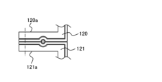
- the saturation tank main body 102 is composed of three parts: an upper cap part 120, a central body part 121, and a bottom base part 122.
- the main material of these parts of the saturation tank body 102 is a highly durable metal such as stainless steel.
- the two parts are sequentially joined to form the saturation tank body 102.
- These three parts are connected by bolt fastening between a flange 120a at the lower end of the peripheral wall of the upper cap part 120 and a flange 121a at the upper end of the peripheral wall of the central body part 121, and a lower end of the peripheral wall of the central body part 121.
- This is done by bolt connection between the flange 121b of the bottom base part 122 and the flange 122a of the outer edge side of the bottom base part 122. Therefore, when those bolts are released, the saturation tank main body 102 is disassembled into three parts.
- the humidity control gas generator 101 When the humidity control gas generator 101 is in operation, water is filled inside the saturation tank main body 102, leaving an area above where the gas should exist.
- the water filled in the saturation tank body 102 is ultrapure water.
- the area filled with water in the saturation tank main body 102 will be referred to as a storage area W, and the upper gas area will be referred to as a gas area G hereinafter.
- the height dimensions of the upper cap part 120 and the central body part 21 of the saturation tank main body 102 are selected so as to satisfy the following conditions. That is, the water surface is located at a height of approximately the upper half of the central body portion 121 and never reaches the upper cap portion 120, so that the inside of the upper cap portion 120 always corresponds to the gas region G.
- a gas heater (heating section) 105 for heating the gas in the gas region G is provided on the outer surface of the peripheral wall of the upper cap section 120 of the saturation tank main body 102. Most of the outer surface of the upper cap part 120 may be covered with the gas heater 105.
- a water heater 106 for heating the water in the storage area W is disposed at a lower portion inside the saturation tank main body 102, for example, at a height position close to the bottom base portion 122.
- the heater may be arranged on the wall of the saturation tank main body 102, for example, on the outer surface of the peripheral wall of the central body portion 121.
- a water heater/cooler capable of heating and cooling water such as a heat pump utilizing the Peltier effect, may be in close contact with the outer surface of the wall of the saturation tank body 102.
- a gas introduction path 122b is formed within the wall of the bottom base portion 122 of the saturation tank main body 102.
- a gas inlet 122c of the gas introduction path 122b opens to the outer surface of the wall of the bottom base portion 122, and a gas outlet 122d thereof opens toward the storage area W of the wall of the bottom base portion 122.
- a porous body 107 is provided at the gas outlet 122d to form fine bubbles B of the gas released from there into the storage area W.
- a reserve water tank 103 is arranged outside the saturation tank main body 102.
- Reserve water tank 103 has an upper part 130 and a lower part 131. These two parts are joined together to form the reserve water tank 103 in such a manner that the upper surface of the wall of the lower part 131 is in close contact with the lower end surface of the peripheral wall of the upper part 130.
- the connection between these two parts is made by a bolt connection between a flange 130a at the lower end of the peripheral wall of the upper part 130 and a flange 131a on the outer edge side of the lower part 131. Therefore, by releasing those bolts, the reserve water tank 103 can be disassembled into two parts.
- the main material of the reserve water tank 103 is a highly durable metal, such as stainless steel.
- An opening 130b is provided in the wall of the upper part 130 of the reserve water tank 103, for example, the ceiling wall, and an opening 120b is provided in the upper wall of the upper cap part 120 of the saturation tank main body 102. They are connected through a communication pipe 108. Further, an opening 131b is provided in the wall of the lower part 31 of the reserve water tank 103, for example, the bottom wall, and an opening 121c is provided in the lower wall of the saturation tank main body 102, for example, the lower circumferential wall of the central body 121. , both openings 131b and 121c are connected by a water communication pipe 109.
- the height dimension of the reserve water tank 103 and the height of its arrangement relative to the saturation tank main body 102 are selected so as to satisfy the following conditions. That is, the height of the water surface falls within the internal height dimension of the reserve water tank 103. Therefore, the water surface height inside the reserve water tank 103 and the water surface height inside the saturation tank main body 102 are equal, and the gas area G and the storage area W also exist inside the reserve water tank 103.
- the inside of the reserve water tank 103 and the inside of the saturation tank main body 102 communicate with each other through both the gas area G and the storage area W. Therefore, when water is consumed and reduced inside the saturation tank main body 102, water is replenished from the reserve water tank 103 into the saturation tank main body 102.
- Another opening 130c is provided in the wall of the reserve water tank 103, and the water supply pipe 110 is connected to the opening 130c. If the water level in the saturation tank falls too low, water can be manually or automatically replenished into the reserve water tank 103 from the water supply pipe 110.
- a gas reflux device 104 is arranged inside the saturation tank main body 102.
- the gas recirculation device 104 includes a gas return pipe 140, a gas delivery pipe 141, a drain pipe 142, and a trap box 143.
- the main material of the gas reflux device 104 is a highly durable metal, such as stainless steel.
- the gas return pipe 140 has a substantially linear shape and is arranged vertically, for example, substantially vertically, and has a gas inlet 140a at its upper end and a gas outlet 140b at its lower end.
- the gas inlet 140a of the gas return pipe 140 is arranged at the upper part of the gas region G in the saturation tank main body 102, for example, at a position close to the ceiling wall of the upper cap part 120.
- the gas return pipe 140 passes from the gas inlet 140a in the gas area G, passes through the storage area W, and reaches the gas outlet 140b inside the trap box 143.
- the gas outlet 140b of the gas return pipe 140 is arranged at a position lower than the uppermost position inside the trap box 143, for example, at a position lowered by a predetermined distance from the top wall of the trap box 143.
- a portion of the gas return pipe 140 near the gas outlet 140b is bent obliquely with respect to the vertical direction and reaches the gas outlet 140b (see FIG. 4).
- the direction of the gas outlet 140b in the horizontal plane is different from the direction in which the gas inlet 141a of the gas delivery pipe 141 exists in the horizontal plane as seen from the gas outlet 140b. Therefore, the gas flow blown out from the gas outlet 140b heads in a different direction from the gas inlet 141a of the gas delivery pipe 41.
- the front end surface 140c of the gas outlet 140b of the gas return pipe 140 is approximately circular, but the front end surface 140c is tilted diagonally so that at least a portion of the circular end surface contacts the inner surface of the trap box 143. It has been cut. More specifically, the gas outlet 140b is disposed near the inner surface of the inner wall of the trap box 143, faces toward the inner surface of the wall, and is located at a portion of the gas outlet 140b (for example, the most distal portion of the gas outlet 140b). (extended tip) is in contact with the inner surface of the trap box 143.
- the central axis of the gas return pipe 140 at the gas outlet 140b of the gas return pipe 140 is inclined in the circumferential direction with respect to the inner surface of the inner wall of the trap box 143.
- a gas temperature sensor 111 that detects the temperature of the gas is arranged in the gas region G at approximately the same height as the gas inlet 140a of the gas return pipe 140.
- a detection signal from the gas temperature sensor 111 is input to a control device (not shown) disposed outside the saturation tank main body 102, and is used for gas temperature control by the gas heater.
- the gas delivery pipe 141 has a curved shape, for example, an inverted L shape, is arranged vertically, has a gas inlet 141a at the lower end of the almost vertical part, and has a gas inlet 141a at the lower end of the almost horizontal part. It has a gas outlet 141b at the upper end.
- the gas inlet 141a of the gas delivery pipe 141 is arranged at a higher position than the gas outlet 140b of the gas return pipe 40 inside the trap box 143.
- the gas delivery pipe 141 extends upward from the gas inlet 141a, exits the trap box 143, enters the storage area W, changes direction almost horizontally, and then extends below the water level on the wall of the central body 121. It penetrates through this point and reaches the gas delivery port 141b arranged outside the saturation tank main body 102.
- a water temperature sensor 112 that detects the temperature of water is arranged at approximately the same height as the gas delivery pipe 141 in the storage area W.
- a detection signal from the water temperature sensor 112 is input to a control device (not shown) disposed outside the saturation tank main body 102 and is used to control the water temperature by the water heater 106.
- the drain pipe 142 has a water inlet 142a located almost at the bottom inside the trap box 143, and a water outlet 142b located outside the saturation tank body 102.
- the drain pipe 142 extends from the water inlet 142a, exits the trap box 143, penetrates the wall of the central body 121, and exits the saturation tank body 102.
- the trap box 143 is arranged within the storage area W in the central body 121 of the saturation tank main body 102 at a higher height than the water heater 106 described above.
- the horizontal cross-sectional area of the trap box 143 is larger than the horizontal cross-sectional area of the gas return pipe 140, and within the trap box 143, the gas outlet 140b of the gas return pipe 140 and the gas inlet 140a of the gas delivery pipe 141 are They are arranged a predetermined distance apart in the horizontal direction. As described above, within the trap box 143, the gas outlet 140b of the gas return pipe 140 faces in a direction different from the direction in which the gas inlet 140a of the gas delivery pipe 141 is viewed from the gas outlet 140b.
- the trap box 143 has a height greater than a predetermined value, and the gas outlet 140b of the gas return pipe 140 is disposed at a lower position than the gas inlet 140a of the gas delivery pipe 141 within the trap box 143. Furthermore, inside the trap box 143, the gas inlet 141a of the gas delivery pipe 141 is arranged at a high position that is a predetermined height away from the bottom surface of the trap box 143 where water collects.
- the entire inner surface of the saturation tank main body 102 in contact with the gas region G and storage region W is made of a corrosion-resistant material that has higher durability against pure water than the main material of the saturation tank main body 102, such as stainless steel, such as a fluororesin (such as Teflon (registered)). Trademark)), coated with a layer of.
- a corrosion-resistant material that has higher durability against pure water than the main material of the saturation tank main body 102, such as stainless steel, such as a fluororesin (such as Teflon (registered)). Trademark)
- the mutual contact surfaces between the upper cap portion 120 and the center body portion 121 of the saturation tank body 102 (the contact surfaces facing each other between the flanges 120a and 121a), and the contact surfaces between the center body portion 121 and the bottom
- the mutual contact surfaces of the base portion 122 are also coated with a layer of the same corrosion-resistant material.
- the inner surface of the reserve water tank 103 in contact with the gas region G and storage region W is also coated with a layer of the same corrosion-resistant material.
- the mutual contact surfaces of the upper part 130 and lower part 131 of the reserve water tank 103 are also coated with the same layer of corrosion-resistant material.
- the outer surface of the gas recirculation device 104 in contact with the gas region G and storage region W (for example, the outer surface of the trap box 43) is also coated with a layer of the same corrosion-resistant material.
- the humidity-controlled gas generator 101 of the present embodiment described above has better water resistance, maintainability, cleanliness of the output gas, or controllability of the humidity of the output gas than conventional humidity-controlled gas generators. It can be expected to be superior to conventional humidity control gas generators.
- the humidity control gas generator 101 of this embodiment can be suitably used in a dry cleaning process in a semiconductor manufacturing process, and can also be used in other semiconductor manufacturing processes, such as humidity control in a stepper in an exposure process, a spin coater, etc. It can also be suitably used for controlling the humidity of the atmosphere during the painting process.
- FIG. 5 shows a modification of the humidity control gas generator 101.
- a water stirring device 150 is added to the saturation tank main body 102 having the same configuration as shown in FIG.
- the water stirring device 150 stirs the water in the saturation tank main body 102 by sucking water from the upper part of the saturation tank main body 102 and returning it to the lower part of the saturation tank main body 102 using a pump. This makes the temperature of the water in the saturation tank body 102 more uniform throughout.
- the flow rate of gas supplied into the saturation tank main body 102 from the gas introduction path 122b is large to a certain extent, the bubbles B stir the water in the saturation tank main body 102 to some extent, so the water stirring device is not necessarily driven. You don't have to.
- the water stirring effect by the bubbles B becomes slight, and stirring the water in the saturation tank main body 102 with the water stirring device will reduce the temperature of the water and the output gas. is preferable for controlling the temperature to a target value.
- the present invention is not limited to the above-described embodiments, and includes various modifications.
- the embodiments described above are described in detail to explain the present invention in an easy-to-understand manner, and the present invention is not necessarily limited to having all the configurations described.
- it is possible to replace a part of the configuration of one embodiment with the configuration of another embodiment and it is also possible to add the configuration of another embodiment to the configuration of one embodiment.
Landscapes
- Physics & Mathematics (AREA)
- Health & Medical Sciences (AREA)
- Life Sciences & Earth Sciences (AREA)
- Chemical & Material Sciences (AREA)
- Analytical Chemistry (AREA)
- Biochemistry (AREA)
- General Health & Medical Sciences (AREA)
- General Physics & Mathematics (AREA)
- Immunology (AREA)
- Pathology (AREA)
- Control Of Non-Electrical Variables (AREA)
Priority Applications (2)
| Application Number | Priority Date | Filing Date | Title |
|---|---|---|---|
| PCT/JP2022/028266 WO2024018573A1 (ja) | 2022-07-20 | 2022-07-20 | 温湿度制御装置、及び、温湿度制御装置と調湿ガス発生装置との組合せ |
| JP2024534844A JP7850476B2 (ja) | 2022-07-20 | 2022-07-20 | 温湿度制御装置、及び、温湿度制御装置と調湿ガス発生装置との組合せ |
Applications Claiming Priority (1)
| Application Number | Priority Date | Filing Date | Title |
|---|---|---|---|
| PCT/JP2022/028266 WO2024018573A1 (ja) | 2022-07-20 | 2022-07-20 | 温湿度制御装置、及び、温湿度制御装置と調湿ガス発生装置との組合せ |
Publications (1)
| Publication Number | Publication Date |
|---|---|
| WO2024018573A1 true WO2024018573A1 (ja) | 2024-01-25 |
Family
ID=89617509
Family Applications (1)
| Application Number | Title | Priority Date | Filing Date |
|---|---|---|---|
| PCT/JP2022/028266 Ceased WO2024018573A1 (ja) | 2022-07-20 | 2022-07-20 | 温湿度制御装置、及び、温湿度制御装置と調湿ガス発生装置との組合せ |
Country Status (2)
| Country | Link |
|---|---|
| JP (1) | JP7850476B2 (https=) |
| WO (1) | WO2024018573A1 (https=) |
Citations (3)
| Publication number | Priority date | Publication date | Assignee | Title |
|---|---|---|---|---|
| JP2010159987A (ja) * | 2009-01-06 | 2010-07-22 | Hitachi High-Technologies Corp | 自動分析装置 |
| JP2011163585A (ja) * | 2010-02-05 | 2011-08-25 | Espec Corp | 恒温恒湿装置 |
| WO2021033260A1 (ja) * | 2019-08-20 | 2021-02-25 | マイクロ・イクイップメント株式会社 | 調湿ガス発生装置 |
-
2022
- 2022-07-20 WO PCT/JP2022/028266 patent/WO2024018573A1/ja not_active Ceased
- 2022-07-20 JP JP2024534844A patent/JP7850476B2/ja active Active
Patent Citations (3)
| Publication number | Priority date | Publication date | Assignee | Title |
|---|---|---|---|---|
| JP2010159987A (ja) * | 2009-01-06 | 2010-07-22 | Hitachi High-Technologies Corp | 自動分析装置 |
| JP2011163585A (ja) * | 2010-02-05 | 2011-08-25 | Espec Corp | 恒温恒湿装置 |
| WO2021033260A1 (ja) * | 2019-08-20 | 2021-02-25 | マイクロ・イクイップメント株式会社 | 調湿ガス発生装置 |
Also Published As
| Publication number | Publication date |
|---|---|
| JPWO2024018573A1 (https=) | 2024-01-25 |
| JP7850476B2 (ja) | 2026-04-23 |
Similar Documents
| Publication | Publication Date | Title |
|---|---|---|
| US20130133703A1 (en) | Vaporized material supply apparatus, substrate processing apparatus having same and vaporized material supply method | |
| US10876750B2 (en) | Humidifier and method for conditioning air | |
| JP2001340800A (ja) | 塗布装置 | |
| WO2024018573A1 (ja) | 温湿度制御装置、及び、温湿度制御装置と調湿ガス発生装置との組合せ | |
| JP2975601B1 (ja) | ガスを中心とした環境試験槽 | |
| WO2019085161A1 (zh) | 一种抗盐类侵蚀试验装置 | |
| KR102224227B1 (ko) | 반도체 제조설비용 진공칠러탱크 | |
| US20110120214A1 (en) | Transdermal diffusion cell testing vessel and methods using same | |
| CN112448003B (zh) | 加湿装置及测试系统 | |
| KR102768408B1 (ko) | 조습 가스 발생 장치 | |
| CN213936273U (zh) | 加湿装置及测试系统 | |
| KR20200064657A (ko) | 부식시험장치 및 부식시험방법 | |
| CN222885624U (zh) | 一种可温控恒温反应装置 | |
| JPH0428350B2 (https=) | ||
| JPS5855926Y2 (ja) | 分流式湿度発生装置 | |
| JPH11243780A (ja) | 切り花保存装置 | |
| JP2010075870A (ja) | 理化学試験用恒温装置 | |
| JP7081851B1 (ja) | 環境試験機および環境試験機の試験槽の加熱方法 | |
| JP6858536B2 (ja) | 加湿器 | |
| HK40044350A (zh) | 调湿气体发生装置 | |
| CN205955820U (zh) | 热力发动机冷却回路的液相调节装置 | |
| CN223454288U (zh) | 恒温槽装置 | |
| JP4813944B2 (ja) | 飽和ガス供給装置 | |
| CN114375132B (zh) | 用于防凝露的电子器件散热系统及水上机械设备 | |
| CN223538131U (zh) | 一种高精度聚合氯化铝加热冷却集成模块 |
Legal Events
| Date | Code | Title | Description |
|---|---|---|---|
| 121 | Ep: the epo has been informed by wipo that ep was designated in this application |
Ref document number: 22951960 Country of ref document: EP Kind code of ref document: A1 |
|
| WWE | Wipo information: entry into national phase |
Ref document number: 2024534844 Country of ref document: JP |
|
| NENP | Non-entry into the national phase |
Ref country code: DE |
|
| 32PN | Ep: public notification in the ep bulletin as address of the adressee cannot be established |
Free format text: NOTING OF LOSS OF RIGHTS PURSUANT TO RULE 112(1) EPC (EPO FORM 1205A DATED 15/05/2025) |
|
| 122 | Ep: pct application non-entry in european phase |
Ref document number: 22951960 Country of ref document: EP Kind code of ref document: A1 |