WO2024014490A1 - 冷却モジュール用バルブ及び冷却モジュール - Google Patents
冷却モジュール用バルブ及び冷却モジュール Download PDFInfo
- Publication number
- WO2024014490A1 WO2024014490A1 PCT/JP2023/025773 JP2023025773W WO2024014490A1 WO 2024014490 A1 WO2024014490 A1 WO 2024014490A1 JP 2023025773 W JP2023025773 W JP 2023025773W WO 2024014490 A1 WO2024014490 A1 WO 2024014490A1
- Authority
- WO
- WIPO (PCT)
- Prior art keywords
- valve
- chamber
- cooling module
- outflow
- inflow
- Prior art date
- Legal status (The legal status is an assumption and is not a legal conclusion. Google has not performed a legal analysis and makes no representation as to the accuracy of the status listed.)
- Ceased
Links
Images









Classifications
-
- F—MECHANICAL ENGINEERING; LIGHTING; HEATING; WEAPONS; BLASTING
- F16—ENGINEERING ELEMENTS AND UNITS; GENERAL MEASURES FOR PRODUCING AND MAINTAINING EFFECTIVE FUNCTIONING OF MACHINES OR INSTALLATIONS; THERMAL INSULATION IN GENERAL
- F16K—VALVES; TAPS; COCKS; ACTUATING-FLOATS; DEVICES FOR VENTING OR AERATING
- F16K27/00—Construction of housing; Use of materials therefor
- F16K27/06—Construction of housing; Use of materials therefor of taps or cocks
- F16K27/065—Construction of housing; Use of materials therefor of taps or cocks with cylindrical plugs
-
- F—MECHANICAL ENGINEERING; LIGHTING; HEATING; WEAPONS; BLASTING
- F16—ENGINEERING ELEMENTS AND UNITS; GENERAL MEASURES FOR PRODUCING AND MAINTAINING EFFECTIVE FUNCTIONING OF MACHINES OR INSTALLATIONS; THERMAL INSULATION IN GENERAL
- F16K—VALVES; TAPS; COCKS; ACTUATING-FLOATS; DEVICES FOR VENTING OR AERATING
- F16K11/00—Multiple-way valves, e.g. mixing valves; Pipe fittings incorporating such valves
- F16K11/02—Multiple-way valves, e.g. mixing valves; Pipe fittings incorporating such valves with all movable sealing faces moving as one unit
- F16K11/08—Multiple-way valves, e.g. mixing valves; Pipe fittings incorporating such valves with all movable sealing faces moving as one unit comprising only taps or cocks
- F16K11/085—Multiple-way valves, e.g. mixing valves; Pipe fittings incorporating such valves with all movable sealing faces moving as one unit comprising only taps or cocks with cylindrical plug
- F16K11/0856—Multiple-way valves, e.g. mixing valves; Pipe fittings incorporating such valves with all movable sealing faces moving as one unit comprising only taps or cocks with cylindrical plug having all the connecting conduits situated in more than one plane perpendicular to the axis of the plug
Definitions
- the present invention relates to a cooling module valve and a cooling module.
- hybrid electric vehicle HEV
- PHEV plug-in hybrid electric vehicle
- BEV battery electric vehicle
- FCEV Fuel Cell Electric Vehicle
- electric vehicles are equipped with batteries for driving motors. Since electric vehicles have many devices that require cooling, such as motors (including internal combustion engines such as engines), batteries, air conditioners, and ECUs, these devices are cooled by configuring a cooling circuit that circulates cooling water. However, these devices may have different appropriate operating temperatures.
- the cooling water that has flowed in inside the valve is moved in the vertical direction and is allowed to flow out.
- the inflow path and the outflow path are formed in a direction crossing the valve housing.
- the arrangement of the inflow path and the outflow path is restricted by the valve, and as a result, the inflow path and the outflow path are restricted by the valve. There is a risk that the routing of the outflow path may become complicated.
- the present invention has been made in view of the above-mentioned problems, and its purpose is to be able to arrange the inlet and outlet channels without being restricted by the height of the valve, and to improve the routing of the inlet and outlet channels.
- An object of the present invention is to provide a valve for a cooling module and a cooling module that have a high degree of freedom.
- valve for a cooling module is a valve for a cooling module that switches a plurality of flow paths including an inflow path and an outflow path for a fluid flowing in the cooling module, wherein the fluid flows through the inflow path.
- the fluid is provided with at least one of the inflow preliminary chamber disposed between the valve chamber and the inflow passage, and the outflow preliminary chamber disposed between the valve chamber and the outflow passage. It flows into the valve chamber via the inflow prechamber and flows out from the valve chamber via the outflow prechamber. Therefore, by appropriately designing the sizes (heights) of the inflow preliminary chamber and the outflow preliminary chamber, the arrangement of the inflow path and the outflow path is not restricted by the height of the cooling module valve. As a result, it was possible to provide a valve for a cooling module with a high degree of freedom in routing the inflow path and the outflow path.
- One embodiment of the cooling module according to the present invention includes a manifold formed by joining a plurality of resin housings, a cooling module valve that is housed in the manifold and switches between a plurality of flow paths, and a cooling module valve that is housed in the manifold and switches between a plurality of flow paths.
- the cooling module valve includes a valve body, a valve chamber accommodating the valve body, and a water pump adjacent to the valve chamber between the valve chamber and the flow path.
- the resin housing has at least a vortex chamber formed among the plurality of channels, the valve chamber, the preliminary chamber, and the water pump, and the resin housing has a , consisting only of the flow path, the valve chamber, the preliminary chamber, the vortex chamber, and partition walls that partition these.
- the manifold can be downsized.
- One embodiment of the cooling module according to the present invention includes a manifold formed by joining a plurality of resin housings, and a cooling module valve accommodated in the manifold and switching a plurality of flow paths,
- the module valve includes a valve chamber and a preliminary chamber disposed adjacent to the valve chamber between the valve chamber and the flow path, and the resin housing includes a plurality of the flow paths, the A valve chamber and the preliminary chamber are formed, the valve chamber includes a first valve chamber and a second valve chamber, and the resin housing includes the first valve chamber and the second valve chamber. It has a valve communication passage that communicates with the valve.
- fluid can be communicated between the first valve chamber and the second valve chamber.
- One embodiment of the cooling module according to the present invention includes a manifold formed by joining a plurality of resin housings at a joint surface, and a cooling module valve housed in the manifold and switching a plurality of flow paths.
- the cooling module valve has a valve body that rotates around a rotation axis, and a valve chamber that accommodates the valve body, and the plurality of flow channels and the valve chamber are formed in the resin housing.
- at least a portion of the plurality of flow paths has a portion protruding outward from the resin housing, and at least a portion of the plurality of flow paths has a portion protruding outward from the resin housing.
- the flow paths include a first flow path group that is a collection of some of the flow paths, and a collection of a plurality of flow paths that are not included in the first flow path group with respect to the first flow path group. a second flow path group arranged offset in a direction along the rotation axis.
- the cooling module can be made compact.
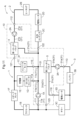
- FIG. 1 is a circuit configuration diagram of a cooling system having a cooling module according to a first embodiment.
- FIG. FIG. 2 is a perspective view of the cooling module.
- FIG. 2 is an exploded perspective view of the cooling module.
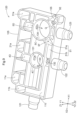
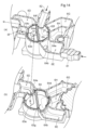
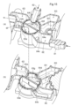
- FIG. 2 is a perspective view of the first housing viewed from the joint surface side.
- FIG. 2 is an exploded perspective view of the cooling module.
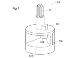
- FIG. 2 is a perspective view of the first valve body of the first rotary valve.
- FIG. 2 is a perspective view of the second valve body of the second rotary valve. is a sectional view taken along the line VIII-VIII in FIG. 3.
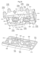
- FIG. 2 is a perspective view of the lower housing viewed from the joint surface side. 2 is a sectional view taken along the line XX in FIG. 2.
- FIG. 2 is a diagram showing the operation of the cooling system.
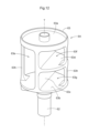
- FIG. 2 is a perspective view of a valve body of a rotary valve in a cooling module according to a second embodiment.
- FIG. 2 is a partially enlarged sectional view of the cooling module.
- FIG. 2 is a cross-sectional view showing the flow of cooling water when the valve body is in the first position.
- FIG. 2 is a cross-sectional view showing the flow of cooling water when the valve body is in the second position.
- FIG. 2 is a cross-sectional view showing the flow of cooling water when the valve body is in the third position.
- FIG. 2 is a perspective view of a cooling module according to a third embodiment.
- FIG. 2 is an exploded perspective view of the cooling module.
- FIG. 3 is a perspective view of a cooling module according to a fourth embodiment. is a sectional view taken along the line XXII-XXII in FIG. 21.
- the cooling system A including the cooling module valve according to the first embodiment includes a first water pump 1A, a radiator 1B, an inverter/motor 1C, a DC-DC converter 1D, a charger 1E, and a reserve.
- the first water pump 1A, the second water pump 2A, the third water pump 3A, the first rotary valve 4, and the second rotary valve 5 are attached to the cooling module 10.
- the radiator 1B, inverter/motor 1C, DC-DC converter 1D, charger 1E, reserve tank 1F, heater core 2B, electric heater 2D, water cooling capacitor 2C, battery 3B, chiller 3C, and electric heater 3D are connected to the cooling module 10.
- the cooling water is configured to flow between the cooling module 10 and the cooling module 10 via a plurality of channels.
- Cooling system A is suitable for use in automobiles equipped with a motor as a driving source, such as hybrid electric vehicles (HEVs), plug-in hybrid electric vehicles (PHEVs), and battery electric vehicles (BEVs). It is used in fuel cell electric vehicles (FCEVs) and the like (hereinafter collectively referred to as "electric vehicles”), and cools the inverter/motor 1C, battery 3B, etc. by circulating cooling water.
- HEVs hybrid electric vehicles
- PHEVs plug-in hybrid electric vehicles
- BEVs battery electric vehicles
- FCEVs fuel cell electric vehicles
- electric vehicles fuel cell electric vehicles
- the radiator 1B cools high temperature cooling water.
- the inverter/motor 1C is a travel drive source that operates with electric power supplied from the battery 3B.
- the DC-DC converter 1D and charger 1E charge the battery 3B.
- the heater core 2B heats the air with high-temperature cooling water to heat the interior of the vehicle. Electric heaters 2D and 3D heat the cooling water when the temperature is low.
- the water-cooled condenser 2C and chiller 3C cool the water when the temperature of the cooling water is high. Battery 3B supplies power to inverter/motor 1C.
- the first water pump 1A pumps cooling water to be supplied to the inverter/motor 1C, DC-DC converter 1D, and charger 1E.
- the second water pump 2A pumps cooling water to be supplied to the heater core 2B, electric heater 2D, and water-cooled condenser 2C.
- the third water pump 3A pumps cooling water to be supplied to the battery 3B, chiller 3C, and electric heater 3D.
- the first water pump 1A, the second water pump 2A, and the third water pump 3A control the flow of the cooling water flowing through the plurality of channels by pumping the cooling water.
- a circulating flow path configured to return to the radiator 1B from the radiator 1B through the first water pump 1A, the inverter/motor 1C, the DC-DC converter 1D, the charger 1E, and the reserve tank 1F
- the first circulation path 1 is referred to as a circulation path 1 (see FIG. 11), and the flow path formed inside the cooling module 10 is referred to as a first flow path 11.
- a circulating flow path configured to return to the heater core 2B from the heater core 2B through the second water pump 2A, the water-cooled condenser 2C, and the electric heater 2D is referred to as a second circulation path 2 (see FIG.
- a flow path formed in the cooling module 10 is referred to as a second flow path 21.
- a circulating flow path configured to return to the battery 3B from the battery 3B through the third water pump 3A, chiller 3C, and electric heater 3D is referred to as the third circulation path 3 (see FIG. 11).
- the flow path formed within the cooling module 10 is referred to as a third flow path 31.
- a communication channel 51 (an example of a channel and an outflow channel) that communicates the first channel 11, the second channel 21, and the third channel 31 is formed.
- the cooling module 10 includes a first water pump 1A, a second water pump 2A, a third water pump 3A, a first rotary valve 4, and a third water pump in the cooling system A. It is configured to include two rotary valves 5 and a manifold 100 in which a flow path is formed to allow cooling water to flow through these two rotary valves.
- the manifold 100 is formed by joining and integrating a plurality of housings, and thereby spans at least two housings (in this embodiment, a first housing 110 and a second housing 120, which will be described later) to provide cooling. It has a plurality of flow channels that allow water to flow through it. Note that, as shown in FIG. 1, the cooling module 10 does not have a reserve tank inside. Since the cooling module 10 does not have a reserve tank, the cooling module 10 can be configured compactly, and the degree of freedom in the arrangement of the cooling module 10 can be increased.
- the manifold 100 is formed by joining and integrating a first housing 110 (an example of a resin housing) and a second housing 120 (an example of a resin housing), both of which are made of resin, by a method such as vibration welding.
- the manifold 100 has a generally rectangular parallelepiped shape as a whole, and as shown in FIGS. 3 and 4, the joint surface 105 between the first housing 110 and the second housing 120 is planar.
- a direction parallel to the longitudinal direction of the joint surface 105 is defined as an X direction
- a direction parallel to the short direction of the joint surface 105 is defined as a Y direction
- a direction perpendicular to the joint surface 105 is defined as a Z direction.
- the joint surface 105 is parallel to the XY plane.
- the direction from the first water pump 1A to the third water pump 3A is defined as the X1 direction, and the opposite direction is defined as the X2 direction.
- the direction from the second outflow port 115 to the first inflow port 111 is defined as the Y1 direction, and the opposite direction is defined as the Y2 direction (the second outflow port 115 and the first inflow port 111 will be described later).
- the direction from the second housing 120 to the first housing 110 is defined as the Z1 direction, and the opposite direction is defined as the Z2 direction.
- the Z2 direction is the direction of gravity. That is, the first housing 110 is arranged vertically above the second housing 120.
- the first housing 110 includes a first inflow port 111, a second inflow port 112, a third inflow port 113, a first outflow port 114, a second outflow port 115, and a second outflow port 115.
- Five outflow ports 116 are formed.
- the second housing 120 is formed with a third outflow port 121, a fourth outflow port 122, and a sixth outflow port 123.
- the first inflow port 111, the second inflow port 112, the third inflow port 113, the first outflow port 114, the second outflow port 115, the third outflow port 121, the fourth outflow port 122, the fifth outflow port 116, and the All six outflow ports 123 have a cylindrical shape.
- the first inflow port 111, the second inflow port 112, and the third inflow port 113 are arranged in parallel so that their respective axes are along the Z direction and on the same plane, and all ports are aligned in the Z1 direction. It has an opening towards the end.
- the first outflow port 114 and the third outflow port 121 are arranged side by side so that their respective axes are along the X direction and on the same plane, and both ports have an opening toward the X2 direction.
- the second outflow port 115 and the fifth outflow port 116 are arranged side by side so that their respective axes are along the Y direction and on the same plane, and both ports have an opening toward the Y2 direction.
- the fourth outflow port 122 and the sixth outflow port 123 are also arranged side by side so that their respective axes are along the Y direction and on the same plane, and both ports have an opening toward the Y2 direction.
- the first inflow port 111, the first outflow port 114, and the second outflow port 115 are included in the first circulation path 1, and all communicate with the first flow path 11.
- the second inflow port 112 and the fourth outflow port 122 are included in the second circulation path 2 and both communicate with the second flow path 21 .
- the third inflow port 113, the fifth outflow port 116, and the sixth outflow port 123 are included in the third circulation path 3, and all communicate with the third flow path 31.
- the first rotary valve 4 and the second rotary valve 5 are connected to the first rotary valve 4 in the first housing 110 when the first housing 110 is viewed along the Z2 direction. It is attached between the inflow port 111, the second inflow port 112, the third inflow port 113, and the second outflow port 115 and the fifth outflow port 116.
- the first rotary valve 4 and the second rotary valve 5 what is exposed at the upper part of the first housing 110 is a valve that rotationally drives the first valve body 4A (an example of a valve body) of the first rotary valve 4.
- the first actuator 4B and the second actuator 5B rotate the second valve body 5A (an example of a valve body) of the second rotary valve 5.
- Both the first valve body 4A and the second valve body 5A are located within the second housing 120 (see FIG. 8). Thereby, the flow paths formed in the second housing 120 can be switched to control the flow of cooling water flowing through the plurality of flow paths.
- the first rotary valve 4 and the second rotary valve 5 are both electromagnetic valves whose flow paths are switched by an actuator, and the first valve body 4A and the second valve body 5A are rotated around an axis along the Z direction. By switching the flow paths, the flow of cooling water flowing through the plurality of flow paths is controlled.
- the first valve body 4A is a three-way valve
- the second valve body 5A is a four-way valve. Details will be described later.
- a first water pump 1A, a second water pump 2A, and a third water pump 3A are installed in the second housing 120 in this order along the X1 direction. It is being At this time, the first water pump 1A, the second water pump 2A, and the third water pump 3A are arranged so that their respective rotation axes are all along the Y direction.
- the second housing 120 includes a first downward sub-channel 11a that communicates with the first inflow port 111 and extends in the Z direction, and a downward sub-channel 11a that communicates with the second inflow port 112 and extends in the Z direction.
- the first water pump 1A pumps the cooling water that flows in from the first inflow port 111 through the first downward sub-flow path 11a.
- the second water pump 2A pumps the cooling water flowing from the second inflow port 112 through the second downward sub-flow path 21a.
- the third water pump 3A pumps the cooling water flowing from the third inflow port 113 through the third downward sub-flow path 31a.
- first downward sub-flow path 11a is a part of the first flow path 11
- second downward sub-flow path 21a is a part of the second flow path 21
- third downward sub-flow path 31a is a part of the first flow path 11. It is a part of the third flow path 31.
- the first water pump 1A, the second water pump 2A, and the third water pump 3A are attached to a mounting portion 125 formed at the end in the Z2 direction (lower end in the vertical direction) of the second housing 120. is attached to.
- the mounting portion 125 is thicker than other parts of the second housing 120. Thereby, even if the second housing 120 is made of resin, it can ensure the strength to attach and hold the heavy first water pump 1A, second water pump 2A, and third water pump 3A.
- the mounting portion 125 includes a first vortex chamber 1Aa in which cooling water that has flowed into the first water pump 1A from the first sub-flow path 11a in the downward direction is rotated after being discharged by rotation of an impeller (not shown);
- a second vortex chamber 2Aa rotates after the cooling water that has flowed into the second water pump 2A from the second sub-flow path 21a is discharged by rotation of the impeller, and a third water pump 3A from the downward third sub-flow path 31a.
- a third vortex chamber 3Aa is formed in which the cooling water that has flowed into the vortex swirls after being discharged by the rotation of the impeller.
- the first water pump 1A, the second water pump 2A, and the third water pump 3A does not require a shroud that regulates the direction of inflow and outflow of cooling water, making it possible to reduce the size, weight, and cost of the cooling module 10.
- the manifold 100 since the manifold 100 has a plurality of flow paths formed across the first housing 110 and the second housing 120, the number of piping can be reduced.
- the manifold 100 since the manifold 100 is constructed by joining the first housing 110 and the second housing 120, the shape and configuration of the flow path in the manifold 100 can be determined by considering the position and direction of the port for connecting the piping. Even if the configuration becomes complicated, the shapes of the first housing 110 and the second housing 120 can be simplified. Thereby, the piping connected to the port can be consolidated and redundant routing can be avoided, so that the length of the piping connected to the port can be shortened and simplified.
- the first rotary valve 4 includes a first valve body 4A, a first valve chamber 4C (an example of a valve chamber), and a first preliminary chamber 4D (an example of an inflow preliminary chamber and a preliminary chamber).
- the second rotary valve 5 includes a second valve body 5A, a second valve chamber 5C (an example of a valve chamber), a second preliminary chamber 5D (an example of an inflow preliminary chamber and a preliminary chamber), and a third preliminary chamber 5E (an example of an outflow preliminary chamber). and an example of a preliminary room) and a fourth preliminary room 5F (an example of an outflow preliminary room and a preliminary room).
- the first valve body 4A is entirely accommodated in the first valve chamber 4C.
- the first valve body 4A has a first shaft 42 that is rotated by the first actuator 4B and a first valve body 43 that rotates integrally with the first shaft 42.
- the first valve main body 43 has a cylindrical shape with walls on the top and bottom and side walls, and a first flow hole 43a, a second flow hole 43b, and a third flow hole 43c, which are through holes, are formed in the side wall 43d.
- the first communication hole 43a, the second communication hole 43b, and the third communication hole 43c are arranged adjacently at intervals of 90 degrees in the circumferential direction, and are connected to each other inside the first valve body 43.
- the first communication hole 43a, the second communication hole 43b, and the third communication hole 43c are all approximately rectangular and have the same opening area.
- the opening areas of the first communication hole 43a, the second communication hole 43b, and the third communication hole 43c are the same as those of the first communication hole 131 (an example of an inlet), the second communication hole 132, and the third communication hole 133, which will be described later. It is larger than the opening area (see Figure 8).
- the second valve body 5A is entirely accommodated in the second valve chamber 5C.
- the second valve body 5A has a second shaft 52 that is rotated by the second actuator 5B and a second valve body 53 that rotates integrally with the second shaft 52.
- the second valve main body 53 has a cylindrical shape, and a fourth communication hole 53a and a fifth communication hole 53b are formed in a side wall 53c.
- the fourth communication hole 53a and the fifth communication hole 53b are connected to each other inside the second valve body 53.
- the fourth communication hole 53a and the fifth communication hole 53b are arranged 180 degrees apart in the circumferential direction.
- Both the fourth communication hole 53a and the fifth communication hole 53b have a rectangular shape, and the fourth communication hole 53a has a larger opening area than the fifth communication hole 53b.
- the opening area of the fifth communication hole 53b is approximately the same as the opening area of each of the fifth communication hole 135 (an example of an outflow port), the sixth communication hole 136, and the seventh communication hole 137 (an example of an outflow port), which will be described later. It is.
- the fourth communication hole 53a has the fifth communication hole 53b, the fifth communication hole 135, the sixth communication hole 136, and the seventh communication hole 137.
- a fourth communication hole 134 (an example of an inlet), which will be described later, even when facing any of the above (see FIG. 8).
- the fourth communication hole 134, the fifth communication hole 135, the sixth communication hole 136, and the seventh communication hole 137 are aligned with the axis P of the fourth communication hole 134,
- the axis Q of the five communicating holes 135, the axis R of the sixth communicating hole 136, and the axis S of the seventh communicating hole 137 are all arranged on the same plane.
- FIGS. 3 and 8 to 10 the flow of cooling water in the cooling module 10 will be explained using FIGS. 3 and 8 to 10.
- the cooling water cooled by the radiator 1B enters the second housing 120 of the cooling module 10 from the first inflow port 111 and flows through the downward first sub-channel 11a in the Z2 direction. , flows into the first water pump 1A.
- the cooling water pumped by the first water pump 1A flows in the Z1 direction through the upward first sub-flow path 11b formed along the Z direction, and passes through the joint surface 105 between the first housing 110 and the second housing 120.
- the first horizontal sub-channel 11c branches from the first upper sub-channel 11b.
- the cooling water flowing in the Z1 direction from the second housing 120 to the first housing 110 through the first sub-flow passage 11b in the upward direction extends from the second housing 120 to the first housing 110. Thereafter, the flow direction is changed to the X2 direction and the fluid flows out from the first outflow port 114.
- the cooling water flowing out of the cooling module 10 from the first outflow port 114 cools the DC-DC converter 1D and the charger 1E, and flows back to the radiator 1B via the reserve tank 1F (see FIG. 1).
- the first lateral sub-flow path 11c is formed across the first housing 110 and the second housing 120, and is formed along the Y direction. That is, the first lateral sub-flow path 11c is formed along the joint surface 105 between the first housing 110 and the second housing 120, and the upper half of the first lateral sub-flow path 11c is formed between the first housing 110 and the second housing 120. The lower half is formed as a second housing 120.
- the first lateral sub-flow path 11c is formed by joining the first housing 110 and the second housing 120.
- the cooling water flows through the first horizontal sub-channel 11c in the Y2 direction, and flows out of the cooling module 10 from the second outflow port 115 provided at the downstream end of the first horizontal sub-channel 11c.
- the cooling water flowing out from the second outflow port 115 cools the inverter/motor 1C and returns to the radiator 1B via the reserve tank 1F (see FIG. 1). Note that the first upward sub-channel 11b and the first lateral sub-channel 11c constitute a part of the first channel 11.
- the cooling water cooled by the heater core 2B enters the second housing 120 of the cooling module 10 from the second inflow port 112 and flows in the downward second sub-channel 21a in the Z2 direction. , flows into the second water pump 2A.
- the cooling water pumped by the second water pump 2A flows in the Z1 direction through an upward second sub-channel 21b (an example of a channel and an inlet channel) formed along the Z direction.
- a first preliminary chamber 4D which is a space communicating with the second upper sub-channel 21b, is formed at the downstream end of the second upper sub-channel 21b.
- the first preliminary chamber 4D is arranged adjacent to the first valve chamber 4C of the first rotary valve 4 in the Y1 direction.
- the first preliminary chamber 4D has a first communication hole 131 opened along the Y direction, and communicates with the first valve chamber 4C via the first communication hole 131.
- the direction of flow of cooling water flowing in the Z1 direction through the upward second sub-flow path 21b is changed to the Y2 direction, and the cooling water flows from the first communication hole 131 into the first valve chamber 4C. It can be distributed. That is, the upward second sub-channel 21b is arranged so as not to overlap the first communication hole 131 in a side view (viewed parallel to the XY plane).
- first valve chamber 4C and the first preliminary chamber 4D are formed astride the second housing 120 and the first housing 110. Thereby, the degree of freedom in the shape (size, height) of the first preliminary chamber 4D can be increased, and the degree of freedom in routing the second upward sub-flow path 21b can be increased.
- the first valve chamber 4C houses the first valve body 4A rotatably about a first shaft 42 along the Z direction. All of the cooling water flowing through the second upward sub-flow path 21b flows into the first valve chamber 4C via the first preliminary chamber 4D and the first communication hole 131.
- the first valve chamber 4C communicates with the lateral second sub flow path 21c (an example of a flow path) via a second communication hole 132 opened along the Y direction, and the first valve chamber 4C communicates with the second horizontal sub flow path 21c (an example of a flow path). It communicates with the fourth flow path 41 via the three communication holes 133.
- the lateral second sub-flow path 21c extends along the Y direction
- the fourth flow path 41 extends along the X direction, both of which are formed within the second housing 120 (see FIG. 3).
- the second downward sub-channel 21a, the second upward sub-channel 21b, the second horizontal sub-channel 21c, the first valve chamber 4C, and the first preliminary chamber 4D are part of the second channel 21.
- the fourth flow path 41 is not a part of the second flow path 21 and does not constitute the second circulation path 2.
- the third communication hole 43c of the first valve body 4A faces the first communication hole 131
- the first communication hole 43a faces the second communication hole 132
- the third communication hole 133 is closed facing the side wall 43d. From this, the cooling water that has flowed into the first valve chamber 4C flows into the second horizontal sub-flow path 21c (the state of the second circulation path 2 in FIG. 11).
- the second flow hole 43b is aligned with the first valve body 43.
- the third communication hole 43c faces the communication hole 131, and the third communication hole 43c faces the third communication hole 133, while the second communication hole 132 faces the side wall 43d and is closed. From this, the cooling water that has flowed into the first valve chamber 4C flows into the fourth flow path 41. In this way, the first rotary valve 4 allows the cooling water that flows through the second upward sub-flow path 21b formed in the cooling module 10 and flows into the first valve chamber 4C via the first preliminary chamber 4D. The outflow path is switched to the lateral second sub-flow path 21c and the fourth flow path 41.
- the cooling water that has flowed from the first valve chamber 4C into the second lateral sub-flow path 21c via the second communication hole 132 flows in the Y2 direction and flows out of the fourth outflow port 122 to the outside of the cooling module 10.
- the cooling water flowing out from the fourth outflow port 122 flows back to the heater core 2B via the water cooling capacitor 2C and the electric heater 2D (see FIG. 1).
- the cooling water that has flowed into the fourth flow path 41 from the first valve chamber 4C via the third communication hole 133 flows in the X2 direction and flows out of the cooling module 10 from the third outflow port 121.
- the cooling water flowing out from the second outflow port 115 flows into the radiator 1B via the reserve tank 1F (see FIG. 1).
- the first rotary valve 4 By rotating the first valve body 4A around the axis along the Z direction by the first actuator 4B, the first rotary valve 4 flows through the second sub-channel 21b in the upward direction and into the first valve chamber 4C.
- the cooling water that has flowed into the sub-channel 21c is switched between the second horizontal sub-channel 21c and the fourth channel 41 to flow therethrough.
- the cooling water that has cooled the battery 3B enters the second housing 120 of the cooling module 10 from the third inflow port 113 and flows through the downward third sub-channel 31a in the Z2 direction. It flows into the third water pump 3A.
- the cooling water pumped by the third water pump 3A flows in the Z1 direction through an upward third sub-flow path 31b (an example of a flow path and an inflow path) formed along the Z direction.
- a second preliminary chamber 5D which is a space communicating with the third upper sub-channel 31b, is formed at the downstream end of the third upper sub-channel 31b.
- the second preliminary chamber 5D is arranged adjacent to the second valve chamber 5C (an example of a valve chamber) of the second rotary valve 5 in the Y1 direction.
- the second preliminary chamber 5D has a fourth communication hole 134 opened along the Y direction, and communicates with the second valve chamber 5C via the fourth communication hole 134.
- second valve chamber 5C and the second preliminary chamber 5D are formed across the second housing 120 and the first housing 110. This increases the degree of freedom in the shape (size, height) of the second preliminary chamber 5D, and increases the degree of freedom in routing the third upward sub-flow path 31b.
- the second valve chamber 5C houses the second valve body 5A rotatably about the second shaft 52 along the Z direction. All of the cooling water flowing through the third upward sub-flow path 31b flows into the second valve chamber 5C via the second preliminary chamber 5D and the fourth communication hole 134.
- the second valve chamber 5C has a sixth communication hole 136 opened along the Y direction, and communicates with the third horizontal sub-flow path 31d via the sixth communication hole 136.
- the second valve chamber 5C also includes a fifth communication hole 135 (an example of an outflow port) and a seventh communication hole 137 (an example of an outflow port) that are opened adjacent to both sides in the circumferential direction with the sixth communication hole 136 in between.
- the third preliminary chamber 5E and the fourth preliminary chamber 5F are formed astride the second housing 120 and the first housing 110. This increases the degree of freedom in the shape (size, height) of the third auxiliary chamber 5E and the fourth auxiliary chamber 5F, and increases the degree of freedom in routing the L-shaped third sub-channel 31c and the communication channel 51. be able to.
- the fourth communication hole 53a of the second valve body 5A faces the fourth communication hole 134
- the fifth communication hole 53b faces the fifth communication hole 135, and the sixth communication hole 136
- the seventh communication hole 137 is closed facing the side wall 53c.
- the cooling water that has flowed into the second valve chamber 5C flows into the third preliminary chamber 5E. That is, the cooling water that has flowed into the second valve chamber 5C flows into an L-shaped third sub-flow path 31c (an example of a flow path and an outflow path), which will be described later.
- the fourth communication hole 53a becomes the fourth communication hole.
- the second rotary valve 5 receives the cooling water that flows through the upward third sub-flow path 31b formed in the cooling module 10 and flows into the second valve chamber 5C via the second preliminary chamber 5D.
- the outflow path is switched to the third auxiliary chamber 5E (L-shaped third sub-channel 31c), the lateral third sub-channel 31d, and the fourth auxiliary chamber 5F (communication channel 51).
- the third preliminary chamber 5E communicates with the fifth outflow port 116 via an L-shaped third sub-channel 31c extending along the Z direction.
- the flow direction of cooling water flowing from the second valve chamber 5C through the fifth communication hole 135 into the third auxiliary chamber 5E in a direction perpendicular to the Z direction can be changed to the Z1 direction.
- the L-shaped third sub-flow path 31c can be made to flow through the third sub-channel 31c so that the liquid can flow out from the fifth outflow port 116 to the outside of the cooling module 10. That is, the L-shaped third sub-channel 31c is arranged so as not to overlap the fifth communication hole 135 when viewed from the side.
- the cooling water flowing out from the fifth outflow port 116 flows back to the battery 3B via the electric heater 3D (see FIG. 1).
- the cooling water that has flowed from the second valve chamber 5C into the third horizontal sub-flow path 31d via the sixth communication hole 136 flows in the Y2 direction and flows out of the sixth outflow port 123 to the outside of the cooling module 10.
- the cooling water flowing out from the sixth outflow port 123 flows back to the battery 3B via the chiller 3C (see FIG. 1).
- the third preliminary chamber 5E constitute a part of the third flow path 31.
- the fourth preliminary chamber 5F communicates with a communication channel 51 that extends from the fourth preliminary chamber 5F in the Z direction and then bends and extends in the X direction. That is, the communication channel 51 is arranged so as not to overlap the seventh communication hole 137 in a side view.
- a first portion 51a of the communication channel 51 extending in the Z direction is formed in the second housing 120, and a second portion 51b extending in the X direction is formed astride the first housing 110 and the second housing 120. has been done. That is, the second portion 51b of the communication channel 51 is formed along the joint surface 105 between the first housing 110 and the second housing 120, and the upper half of the second portion 51b is formed in the first housing 110. , the lower half is formed in the second housing 120.
- the communication flow path 51 is not a part of the third flow path 31 and does not constitute the third circulation path 3.
- the communication channel 51 connects the first channel 11, the second channel 21, and the third channel 31 within the cooling module 10.
- the communication flow path 51 By providing the communication flow path 51 in this way, the three circulation paths through which the cooling water circulates can be consolidated, so the number of piping connected to the port can be reduced, and the length of the piping can be shortened. It can be simplified.
- the second portion 51b of the communication channel 51 communicates with the first horizontal sub-channel 11c at the end opposite to the fourth preliminary chamber 5F. Moreover, the second portion 51b intersects with the lateral second sub-flow path 21c when viewed along the Z direction. The second portion 51b is recessed in the Z2 direction and communicates with the lateral second sub-channel 21c at the intersection.
- the second rotary valve 5 is caused to flow into the second valve chamber 5C from the upward third sub-channel 31b by rotating the second valve body 5A around the axis along the Z direction by the second actuator 5B.
- the cooling water (1) is caused to flow through the third preparatory chamber 5E and the L-shaped third sub-channel 31c through the fifth communication hole 135 and flow out from the fifth outflow port 116; (2) the seventh communication hole 137 (3) from the seventh communication hole 137 to the fourth auxiliary chamber 5F and the communication channel 51 and flow out from the second outflow port 115.
- the fluid flows through the passage 21c to flow out from the second outflow port 115 and the fourth outflow port 122, and flows through the third lateral sub-flow channel 31d through the sixth communication hole 136 to flow out from the sixth outflow port 123. , and distribute it in three ways.
- the L-shaped third sub-channel 31c is arranged so as not to overlap with the fifth communication hole 135, and the communication channel 51 is arranged so as not to overlap with the seventh communication hole 137.
- a rotary valve 6 (an example of a cooling module valve) according to a second embodiment will be described using the drawings.
- the rotary valve 6 of this embodiment is used in the cooling module 20.
- the cooling module 20 differs from the cooling module 10 according to the above embodiment in the flow path configuration.
- the rotary valve 6 includes a valve body 6A, a valve chamber 6C, a first preliminary chamber 6D (an example of an inflow preliminary chamber and a preliminary chamber), and a second preliminary chamber 6E (an example of an inflow preliminary chamber and a preliminary chamber). (an example of a preliminary room), a third preliminary room 6F (an example of an outflow preliminary room and a preliminary room), and a fourth preliminary room 6G (an example of an outflow preliminary chamber and a preliminary chamber).
- the valve body 6A is entirely housed in the valve chamber 6C. As shown in FIG.
- the valve body 6A includes a shaft 62 that rotates around a rotation axis T by an actuator 6B and a valve body 63 that rotates integrally with the shaft 62.
- the valve body 63 includes two discs 63a and 63b arranged vertically apart, and a connecting plate that includes the rotation axis T of the shaft 62 and is arranged to connect the two discs 63a and 63b.
- 63c, a semicircular partition plate 63d arranged perpendicularly to the connecting plate 63c at the center of the connecting plate 63c, and two support columns connecting the two discs 63a and 63b.
- a first valve space 63e (an example of a valve space) is formed by the two discs 63a, 63b and the connecting plate 63c
- a second valve space 63f (an example of a valve space) is formed by the disc 63a, the connecting plate 63c, and the partition plate 63d
- a third valve space 63g (an example of a valve space) is formed by the disk 63b, the connecting plate 63c, and the partition plate 63d. That is, the connection plate 63c divides the space into a plurality (in this embodiment, two) of spaces (a space in which the first valve space 63e, the second valve space 63f, and the third valve space 63g are integrated) in the circumferential direction. ing.
- At least one of the spaces is further divided into a plurality of (in this embodiment, two) spaces (a second valve space 63f and a third valve space 63g) in the direction along the rotation axis T by a partition plate 63d. ing.
- the first valve space 63e, the second valve space 63f, and the third valve space 63g are divided by the disks 63a, 63b, the connecting plate 63c, and the partition plate 63d. and do not communicate with each other.
- the manifold of the cooling module 20 is formed by joining and integrating a first housing 70 (an example of a resin housing) and a second housing 80 (an example of a resin housing), both of which are made of resin, by a method such as vibration welding.
- a valve chamber 6C is arranged in the second housing 80, and adjacent to the periphery of the valve chamber 6C are a first preliminary chamber 6D, a second preliminary chamber 6E, a third preliminary chamber 6F, a fourth preliminary chamber 6G, and a fourth preliminary chamber 6C.
- Five preliminary rooms 6H are arranged.
- the first preliminary chamber 6D, the second preliminary chamber 6E, the third preliminary chamber 6F, the fourth preliminary chamber 6G, and the fifth preliminary chamber 6H are formed astride the second housing 80 and the first housing 70. This increases the degree of freedom in the shape (size, height) of each preparatory chamber, and increases the degree of freedom in routing the inlet and outlet channels, which will be described later.
- the direction parallel to the cut plane shown in FIG. 13 and perpendicular to the axis 62 is defined as the X direction
- the direction perpendicular to the cut plane is defined as the Y direction
- the direction parallel to the axis 62 is defined as the Z direction.
- the direction from the valve body 6A toward the fifth preliminary chamber 6H is defined as the X1 direction
- the opposite direction is defined as the X2 direction.
- the direction from the valve body 6A toward a third inflow path 82 which will be described later, is defined as the Y2 direction
- the opposite direction is defined as the Y1 direction.
- the direction from the second housing 80 to the first housing 70 is defined as the Z1 direction, and the opposite direction is defined as the Z2 direction.
- the Z2 direction is the direction of gravity. That is, the first housing 70 is arranged above the second housing 80 in the vertical direction.
- the first preliminary chamber 6D is connected to a first inflow path 71 (an example of a flow path and an inflow path) formed in the first housing 70 and into which cooling water flows.
- the second preliminary chamber 6E is formed in the second housing 80 and is connected to a second inflow path 81 (an example of a flow path and an inflow path) through which cooling water flows through a seventh communication hole 64g (an example of an inflow port).
- the third preliminary chamber 6F is formed across the first housing 70 and the second housing 80, and includes a first outflow path 72 (an example of a flow path and an outflow path) through which cooling water flows out and an eighth communication hole 64h (outflow port). example).
- the fourth preliminary chamber 6G is formed in the first housing 70 and is connected to a second outflow path 73 (an example of a flow path and an outflow path) through which cooling water flows out.
- the fifth preliminary chamber H is formed in the second housing 80 and is connected to a third outflow path 74 (an example of a flow path and an outflow path) through which cooling water flows out through a ninth communication hole 64i (an example of an outflow port).
- the valve body 6A is formed in the second housing 80 and is connected to a third inflow path 82 (an example of a flow path) into which cooling water flows. No preliminary chamber is formed between the third inflow path 82 and the valve body 6A.
- the valve body 6A and the first preliminary chamber 6D communicate with each other via a first communication hole 64a (an example of an inlet) formed in the valve chamber 6C.
- the valve body 6A and the second preliminary chamber 6E communicate with each other via a second communication hole 64b (an example of an inlet) formed in the valve chamber 6C.
- the valve body 6A and the third preliminary chamber 6F communicate with each other via a third communication hole 64c (an example of an outflow port) formed in the valve chamber 6C.
- the valve body 6A and the fourth preliminary chamber 6G communicate with each other via a fourth communication hole 64d (an example of an outflow port) formed in the valve chamber 6C.
- the valve body 6A and the fifth preliminary chamber 6H communicate with each other via a fifth communication hole 64e (an example of an outflow port) formed in the valve chamber 6C.
- the valve body 6A and the third inflow path 82 communicate with each other via a sixth communication hole 64f formed in the valve chamber 6C.
- the first communication hole 64a, the second communication hole 64b, and the fourth communication hole 64d are located in the Z2 direction from the partition plate 63d in the valve body 6A and in a side view (viewed parallel to the XY plane) of the third valve.
- the respective axes (not shown) of the first communication hole 64a, the second communication hole 64b, and the fourth communication hole 64d are on the same plane.
- the third communication hole 64c, the fifth communication hole 64e, and the sixth communication hole 64f are arranged in the valve body 6A in the Z1 direction relative to the partition plate 63d and at a position overlapping with the second valve space 63f in a side view.
- the respective axes (not shown) of the third communication hole 64c, the fifth communication hole 64e, and the sixth communication hole 64f are on the same plane.
- the inflow and outflow ports can be arranged at two different heights, compared to a rotary valve that has multiple inflow and outflow ports arranged at different heights. Therefore, the height of the rotary valve 6 can be reduced, and the cooling module 20 can be downsized.
- the first communicating hole 64a and the third communicating hole 64c have different height positions, and communicate with each other via the first valve space 63e of the valve body 6A disposed in the valve chamber 6C.
- FIGS. 14 to 16 are cross-sectional views taken along the line aa in FIG. 13, and (b) are cross-sectional views taken along the line b-b of FIG. 13.
- the first valve space 63e of the valve body 6A faces the first preliminary chamber 6D and the third preliminary chamber 6F
- the second valve space 63f of the valve body 6A faces the third preliminary chamber 6D
- the third valve space 63g of the valve body 6A faces the second preliminary chamber 6E and the fourth preliminary chamber 6G.
- the cooling water that has flowed into the first preliminary chamber 6D from the first inflow path 71 flows into the third preliminary chamber 6F via the first communication hole 64a, the first valve space 63e, and the third communication hole 64c. , flows out into the first outflow path 72 (see also FIG. 13).
- the cooling water that has flowed into the third inflow path 82 flows into the fifth preliminary chamber 6H via the sixth communication hole 64f, the second valve space 63f, and the fifth communication hole 64e, and flows out into the third outflow path 74 ( (See also Figure 13).
- the cooling water that has flowed into the second preliminary chamber 6E from the second inflow path 81 flows into the fourth preliminary chamber 6G via the second communication hole 64b, the third valve space 63g, and the fourth communication hole 64d, and then flows into the fourth preliminary chamber 6G through the second communication hole 64b, the third valve space 63g, and the fourth communication hole 64d. 73 (see also FIG. 13).
- the first valve space 63e of the valve body 6A faces the second preliminary chamber 6E and the third preliminary chamber 6F
- the second valve space 63f of the valve body 6A faces the third preliminary chamber 6E
- the third valve space 63g of the valve body 6A faces the first preparatory chamber 6D and the fourth preparatory chamber 6G.
- the cooling water that has flowed into the second preliminary chamber 6E from the second inflow path 81 flows into the third preliminary chamber 6F via the second communication hole 64b, the first valve space 63e, and the third communication hole 64c, It flows out into the first outflow path 72 (see also FIG. 13).
- the cooling water that has flowed into the third inflow path 82 flows into the fifth preliminary chamber 6H via the sixth communication hole 64f, the second valve space 63f, and the fifth communication hole 64e, and flows out into the third outflow path 74 ( (See also Figure 13).
- the cooling water that has flowed into the first preliminary chamber 6D from the first inflow path 71 flows into the fourth preliminary chamber 6G via the first communication hole 64a, the third valve space 63g, and the fourth communication hole 64d, and then flows into the fourth preliminary chamber 6G through the first communication hole 64a, the third valve space 63g, and the fourth communication hole 64d. It flows out into the outflow path 73 (see also FIG. 13).
- the first valve space 63e of the valve body 6A faces the second preliminary chamber 6E and the fifth preliminary chamber 6H
- the second valve space 63f of the valve body 6A faces the third inlet.
- the third valve space 63g of the valve body 6A faces the first preparatory chamber 6D and the fourth preparatory chamber 6G.
- the cooling water that has flowed into the second preliminary chamber 6E from the second inflow path 81 flows into the fifth preliminary chamber 6H via the second communication hole 64b, the first valve space 63e, and the fifth communication hole 64e, It flows out into the third outflow path 74 (see also FIG. 13).
- the cooling water that has flowed into the third inflow path 82 flows into the third preliminary chamber 6F via the sixth communication hole 64f, the second valve space 63f, and the third communication hole 64c, and flows out into the first outflow path 72 (see FIG. (See also 13).
- the cooling water that has flowed into the first preliminary chamber 6D from the first inflow path 71 flows into the fourth preliminary chamber 6G via the first communication hole 64a, the third valve space 63g, and the fourth communication hole 64d, and then flows into the fourth preliminary chamber 6G through the first communication hole 64a, the third valve space 63g, and the fourth communication hole 64d. It flows out into the outflow path 73 (see also FIG. 13).
- the first preliminary chamber 6D is provided, even if the first inflow path 71 is arranged above the rotary valve 6 (in the Z1 direction) and extends along the Z direction, the flow The cooling water can be caused to flow into the valve chamber 6C by changing the direction by 90 degrees.
- the third preliminary chamber 6F is provided, even if the first outflow path 72 is arranged above and apart from the rotary valve 6 and extends along the X direction, the cooling water flowing out from the valve chamber 6C Cooling water can be made to flow through the first outflow path 72 by changing the height in the Z direction.
- the fourth auxiliary chamber 6G is provided, even if the second outflow path 73 is arranged above and apart from the rotary valve 6 and extends along the Z direction, the cooling that has flowed out from the valve chamber 6C Cooling water can be made to flow through the second outflow path 73 by changing the height and direction of the water in the Z direction. Furthermore, since the fifth auxiliary chamber 6H is provided, even if the third outflow path 74 is arranged above and apart from the rotary valve 6 and extends along the X direction, the cooling that flows out from the valve chamber 6C Cooling water can be made to flow through the third outflow path 74 by changing the height of the water in the Z direction.
- the arrangement of the inflow path and the outflow path is not restricted by the height (length along the Z direction) of the rotary valve 6. Further, since the heights of the inflow path and the inlet and/or the heights of the outflow path and the outflow port can be made different, the degree of freedom in routing the inflow path and the outflow path can be increased.
- FIGS. 17 to 20 a cooling module 300 using a first rotary valve 340 (an example of a cooling module valve) and a second rotary valve 350 (an example of a cooling module valve) according to the third embodiment will be described using FIGS. 17 to 20. I will explain.
- the cooling module 300 of this embodiment is different from the cooling modules 10 and 20 according to each of the embodiments described above in the flow path configuration.
- the cooling module 300 includes a first rotary valve 340, a second rotary valve 350, a first water pump 360 (an example of a water pump), and a second water pump 370. (an example of a water pump) and a manifold 302 in which a plurality of flow paths 312 (an example of an inflow path and an outflow path) (see FIG. 19) are formed to allow cooling water to flow therethrough.
- the manifold 302 is formed by joining and integrating a plurality of housings, and in this embodiment, as shown in FIG. 20, it is formed by joining a first housing 310 and a second housing 330. ing.
- the plurality of flow paths 312 shown in FIG. 19 include an inlet path that allows cooling water to flow into the first rotary valve 340 or the second rotary valve 350, and an inlet path that allows the cooling water to flow out from the first rotary valve 340 or the second rotary valve 350.
- This concept includes both outflow channels.
- the plurality of flow paths 312 include a flow path formed only in the first housing 310, a flow path formed only in the second housing 330, and a flow path formed spanning from the first housing 310 to the second housing 330.
- This concept includes all channels through which cooling water flows inside the manifold 302, such as channels that flow inside the manifold 302.
- the flow path 312 having a portion protruding outward from the outer wall 310a of the first housing 310 is connected to the second housing 330 in a direction along the rotation axis AX of the first rotary valve 340.
- a plurality (five in this embodiment) are arranged on the side closer to the second housing 330, and a plurality (four in this embodiment) are arranged on the side far from the second housing 330.
- the five channels 312 whose entire external appearance of the protruding portions are depicted are the channels 312 on the side closer to the second housing 330.
- the four channels 312 whose protruding portions are depicted in cross section are the channels 312 on the side far from the second housing 330.
- the central axes of these nine channels 312 along the protruding direction are all perpendicular to the rotation axis AX (see FIG. 18).
- the five flow paths 312 located closer to the second housing 330 pass through the central axis CX of the protruding portion of any one of the flow paths 312 and extend toward the rotation axis AX. It intersects with the vertical virtual plane P1 (see FIG. 17).
- a set of five channels 312 having such a positional relationship is referred to as a first channel group 312a.
- the four channels 312 other than the five channels 312 of the first channel group 312a are imaginary that passes through the central axis DX of the protruding portion of any one of the channels 312 and is perpendicular to the rotation axis AX. It intersects plane P2 (see FIG. 17).
- a set of four channels 312 having such a positional relationship is referred to as a second channel group 312b. That is, the second channel group 312b is arranged offset from the first channel group 312a in the direction along the rotation axis AX.
- At least one channel 312 of the first channel group 312a and the second channel group 312b has a first communicating hole 316a (an example of an inlet or an outlet) and a second communicating hole 316a (an example of an inlet or an outlet). It communicates with the first valve chamber 316 (an example of a valve chamber) via a hole 316b (an example of an inlet or an outlet).
- the axial center (not shown) of the first communication hole 316a and the axial center (not shown) of the second communication hole 316b have different height positions in the direction along the rotation axis AX.
- the first rotary valve 340, the second rotary valve 350, the first water pump 360, and the second water pump 370 are all attached to the first housing 310. installed.
- the first rotary valve 340 and the first water pump 360 are arranged next to each other, and the second rotary valve 350 and the second water pump 370 are arranged next to each other.
- the rotation axis AX of the first rotary valve 340 and the rotation axis AX of the second rotary valve 350 are parallel, and the rotation axis BX of the first water pump 360 and the rotation axis BX of the second water pump 370 are parallel.
- the rotation axes AX of the first rotary valve 340 and the second rotary valve 350 and the rotation axes BX of the first water pump 360 and the second water pump 370 are perpendicular to each other. Only some of the plurality of channels 312 are formed in the second housing 330 (see FIG. 20).
- the first rotary valve 340 includes a first actuator 341, a first valve body 342 (an example of a valve body), a first valve chamber 316, and a plurality of preliminary chambers 314 (inflow reserve) formed around the first valve chamber 316. (an example of a room or an outflow preliminary room).
- the second rotary valve 350 includes a second actuator 351, a second valve body 352 (an example of a valve body), a second valve chamber 318 (an example of a valve chamber), and a plurality of valve bodies formed around the second valve chamber 318. It has a spare room 314. Among these, the first valve chamber 316, the second valve chamber 318, and the preliminary chamber 314 are formed in the first housing 310.
- the first valve chamber 316 and the second valve chamber 318 accommodate the entirety of the first valve body 342 and the second valve body 352, respectively.
- the first valve chamber 316 and the second valve chamber 318 are formed in the first housing 310 and are located at the center between the pair of opposing outer walls 310a and between the first water pump 360 and the second water pump 370. It is arranged in region 310b.
- the first actuator 341 and the second actuator 351 are exposed on the surface of the first housing 310.
- the first valve body 342 is partitioned into a plurality of (two in this embodiment) spaces in the circumferential direction by a connecting plate 342a, and at least one of them is divided into a plurality of spaces (two in this embodiment).
- the two (one in this embodiment) space is further divided into a plurality of (two in this embodiment) spaces in the direction along the rotation axis AX by the partition plate 342b.
- a space partitioned by the connecting plate 342a and without the partition plate 342b inside is called a first valve space 342c
- a space partitioned by the connecting plate 342a and the partition plate 342b is called a second valve space 342d and a third valve space 342e.
- the second valve body 352 is also divided into three valve spaces.
- the first communication hole 316a and the second communication hole 316b communicate with each other when facing the first valve space 342c of the first valve body 342, and when there is a partition plate 342b between them, the first communication hole 316a and the second communication hole 316b communicate with each other. It faces either the second valve space 342d or the third valve space 342e, and does not communicate with each other.
- a plurality of auxiliary chambers 314 are formed between the flow path 312 and the first valve chamber 316 and between the flow path 312 and the second valve chamber 318, and are connected to the flow path 312 and the first valve chamber 316 via the auxiliary chamber 314.
- the flow path 312 and the second valve chamber 318 are in communication with each other.
- the concept of the preliminary chamber 314 includes both an inflow preliminary chamber connected to the inflow path and an outflow preliminary chamber connected to the outflow path.
- the preliminary chamber 314 is arranged in all the flow paths 312 communicating with the first valve chamber 316 and in all the flow paths 312 communicating with the second valve chamber 318.
- the plurality of flow paths 312 and the plurality of preliminary chambers 314 are arranged radially to surround each of the first valve chamber 316 and the second valve chamber 318.
- the first housing 310 includes a flow passage 312, a first valve chamber 316, a second valve chamber 318, a preliminary chamber 314, a first vortex chamber 320, and a second vortex chamber 322, which are adjacent to each other.
- a first partition wall 324 (an example of a partition wall) is formed to partition two parts.
- the first housing 310 is composed only of a flow path 312, a first valve chamber 316, a second valve chamber 318, a preliminary chamber 314, a first vortex chamber 320, a second vortex chamber 322, and a first partition wall 324.
- a second partition wall 332 (an example of a partition wall) is formed in the second housing 330 to partition a portion of the plurality of channels 312 formed in the second housing 330 and two adjacent ones of the preliminary chambers 314. ing.
- the manifold 302 is formed by joining the first partition wall 324 of the first housing 310 and the second partition wall 332 of the second housing 330.
- FIGS. 21 and 22 a cooling module 400 using a first rotary valve 440 (an example of a cooling module valve) and a second rotary valve 450 (an example of a cooling module valve) according to the fourth embodiment will be described using FIGS. 21 and 22. I will explain.
- the cooling module 400 of this embodiment differs from the cooling modules 10, 20, and 300 according to each of the above embodiments in flow path configuration.
- the cooling module 400 includes a first rotary valve 440, a second rotary valve 450, a first water pump 460 (an example of a water pump), a second water pump 470 (an example of a water pump),
- the manifold 402 includes a manifold 402 in which a plurality of channels 412 are formed to allow cooling water to flow therethrough.
- the manifold 402 is formed by joining and integrating a plurality of housings, and in this embodiment, it is formed by joining a first housing 410 and a second housing 430.
- the plurality of flow paths 412 include an inflow path that allows cooling water to flow into the first rotary valve 440 or the second rotary valve 450, and an outflow path that allows the cooling water to flow out from the first rotary valve 440 or the second rotary valve 450. It is a concept that includes both. Further, the plurality of flow paths 412 include a flow path formed only in the first housing 410, a flow path formed only in the second housing 430, and a flow path formed spanning from the first housing 410 to the second housing 430. This concept includes all channels through which cooling water flows inside the manifold 402, such as the channels inside the manifold 402.
- the first rotary valve 440 and the second rotary valve 450 are attached to the first housing 410, and the first water pump 460 and the second water pump 470 are attached to the second housing 430.
- the rotation axis AX of the first rotary valve 440, the rotation axis AX of the second rotary valve 450, the rotation axis BX of the first water pump 360, and the rotation axis BX of the second water pump 370 are all parallel. .
- the first rotary valve 440 includes a first actuator 441, a first valve body 442 (an example of a valve body), a first valve chamber 416 (an example of a valve chamber), and a first valve chamber 416. It has a preliminary chamber 414 formed around the .
- the second rotary valve 450 includes a second actuator 451, a second valve body 452 (an example of a valve body), a second valve chamber 418 (an example of a valve chamber), and a preliminary chamber formed around the second valve chamber 418. 414.
- the first valve chamber 416, the second valve chamber 418, and the preliminary chamber 414 are formed in the first housing 410.
- the first valve chamber 416 and the second valve chamber 418 accommodate the entirety of the first valve body 442 and the second valve body 452, respectively.
- the first actuator 441 and the second actuator 451 are exposed on the surface of the first housing 410.
- the preliminary chamber 414 is formed between the flow path 412 and the first valve chamber 416 and between the flow path 412 and the second valve chamber 418, and is connected to the flow path 412 and the first valve chamber 416 via the preliminary chamber 414.
- the flow path 412 and the second valve chamber 418 are in communication.
- the concept of the preliminary chamber 414 includes both an inflow preliminary chamber connected to the inflow path and an outflow preliminary chamber connected to the outflow path.
- the preparatory chamber 414 is arranged everywhere between the first valve chamber 416 and the flow path 412 and between the second valve chamber 418 and the flow path 412.
- a preliminary chamber 414 is arranged between the valve communication passage 424 and the first valve chamber 416 and the second valve chamber 418.
- each preliminary chamber is formed across the first housing and the second housing, but it may be formed only in the first housing, or only in the second housing. It may also be configured such that it is formed.
- the first valve chamber 416 of the first rotary valve 440 and the second valve chamber 318 of the second rotary valve 450 communicated with each other through the preliminary chamber 414 and the valve communication passage 424.
- the valve communication passage 424 may be omitted, and the preliminary chamber 414 alone may be used for communication. Alternatively, the preliminary chamber 414 may not be provided and the valve communication passage 424 may be used for communication.
- valve for a cooling module is a valve for a cooling module that switches between a plurality of flow paths including an inflow path and an outflow path for fluid flowing in the cooling module, and in which a fluid flows through the inflow path.
- a valve chamber through which the fluid flowing through the outflow channel flows out as the fluid flows in;
- a valve body that is accommodated in the valve chamber and switches between the plurality of flow channels;
- the fluid is provided with at least one of the inflow preliminary chamber disposed between the valve chamber and the inflow passage, and the outflow preliminary chamber disposed between the valve chamber and the outflow passage. It flows into the valve chamber via the inflow prechamber and flows out from the valve chamber via the outflow prechamber. Therefore, by appropriately designing the sizes (heights) of the inflow preliminary chamber and the outflow preliminary chamber, the arrangement of the inflow path and the outflow path is not restricted by the height of the cooling module valve. As a result, it was possible to provide a valve for a cooling module with a high degree of freedom in routing the inflow path and the outflow path.
- the outflow port to the outflow path, or the inflow port from the inflow path to the inflow preliminary chamber, and the inflow port from the inflow preliminary chamber to the valve chamber are defined by heights in the direction of the rotation axis of the valve body.
- the arrangement of the inlet and outlet channels can be freely set by changing the height of the preliminary chamber.
- the valve chamber has an inlet that communicates with the inflow preliminary chamber, and an outlet that communicates with the outflow preliminary chamber, and the inlet
- the axis of the outlet and the axis of the outlet are arranged on the same plane.
- the heights of the inlet and the outlet can be made the same, the height of the cooling module valve can be lowered, and the cooling module can be downsized.
- At least one of the inflow path and the outflow path is arranged so as not to overlap with the inflow port and the outflow port in a side view.
- At least one of the inflow path and the outflow path is arranged so as not to overlap with the inflow port and the outflow port in a side view, so that the height of the inflow path and the inflow port and/or the height of the outflow path and the outflow port is
- the heights of the inflow and outflow channels can be made different, increasing the degree of freedom in routing the inflow and outflow channels.
- At least one of the inflow preliminary chamber and the outflow preliminary chamber is formed across a plurality of resin housings.
- the degree of freedom in the shape (size, height) of the inflow preliminary chamber and/or the outflow preliminary chamber is increased, and the degree of freedom in routing the inflow path and the outflow path can be increased.
- At least one of the outflow passages communicates with another of the flow passages in the cooling module, and the outflow passage spans the plurality of resin housings. It is formed by
- the entire valve body is accommodated in the valve chamber.
- the cooling module valve can be downsized.
- valve body rotates around a rotation axis, and is partitioned into a plurality of valve spaces in the circumferential direction by a connecting plate, and at least one The valve space is further divided into a plurality of sections in the direction of the rotation axis by a partition plate.
- valves that would normally be required can be combined into one.
- a partition plate since it has a partition plate, a plurality of independent flow paths can be formed in the direction of the rotation axis.
- the valve space without a partition plate allows ports at different height positions to communicate within the valve body, making it possible to make the valve more compact.
- valve chamber has an inlet and an outlet having different axis height positions in a direction along the rotation axis.
- the valve chamber has an inlet and an outlet having different axis height positions in the direction along the rotation axis, so the valve can be made compact.
- the inflow preliminary chamber and the outflow preliminary chamber are arranged between the valve chamber and all the inflow passages, and between the valve chamber and all the outflow passages. is located between.
- the heights of the inflow port formed in the inflow path and the valve chamber and/or the heights of the outflow port formed in the outflow path and the valve chamber can be made different, so that the inflow path and the outflow path can be made different in height.
- the degree of freedom in routing can be increased.
- One embodiment of the cooling module includes a manifold formed by joining a plurality of resin housings, a cooling module valve that is housed in the manifold and switches between a plurality of flow paths, and a cooling module valve that flows through the flow paths.
- a water pump that pumps fluid
- the cooling module valve includes a valve body, a valve chamber accommodating the valve body, and a valve chamber adjacent to the valve chamber between the valve chamber and the flow path;
- the resin housing has at least a vortex chamber formed among the plurality of channels, the valve chamber, the preliminary chamber, and the water pump, and the resin housing has a It is composed only of the flow path, the valve chamber, the preparatory chamber, the vortex chamber, and a partition wall that partitions these.
- the manifold can be downsized while achieving the effect of (1) above.
- One embodiment of the cooling module includes a manifold formed by joining a plurality of resin housings, and a cooling module valve accommodated in the manifold and switching a plurality of flow paths, the cooling module
- the valve has a valve chamber and a preliminary chamber arranged adjacent to the valve chamber between the valve chamber and the flow path, and the resin housing includes a plurality of the flow paths and the valve chamber.
- the valve chamber includes a first valve chamber and a second valve chamber, and the resin housing includes a first valve chamber and a second valve chamber. It has a valve communication path for communication.
- fluid can be communicated between the first valve chamber and the second valve chamber via the valve communication passage while achieving the effect of (1) above.
- One embodiment of the cooling module includes a manifold formed by joining a plurality of resin housings at a joint surface, and a cooling module valve accommodated in the manifold and switching a plurality of flow paths,
- the cooling module valve has a valve body that rotates around a rotation axis and a valve chamber that accommodates the valve body, and the plurality of flow channels and the valve chamber are formed in the resin housing.
- At least a portion of the plurality of flow paths has a portion projecting outward from the resin housing, and at least a portion of the plurality of flow paths has a portion projecting outward from the resin housing.
- the channels include a first channel group, which is a collection of some of the channels, and a plurality of channels that are not included in the first channel group, with respect to the first channel group. and a second flow path group arranged offset in the direction along the rotation axis.
- the cooling module can be made compact.
- the valve body of the cooling module valve rotates around the rotation axis, and is partitioned into a plurality of valve spaces in the circumferential direction by a connecting plate, and at least One of the valve spaces is further divided into a plurality of spaces in the direction of the rotation axis by a partition plate.
- valves that would normally be required can be combined into one.
- a partition plate since it has a partition plate, a plurality of independent flow paths can be formed in the direction of the rotation axis. Further, in the valve space without a partition plate, ports at different height positions can be communicated within the valve body, so the valve can be made compact and the cooling module can be downsized.
- valve chamber has an inlet and an outlet having different axis height positions in a direction along the rotation axis.
- the valve chamber has an inlet and an outlet having different axis height positions in the direction along the rotation axis, so the valve can be made compact and the cooling module can be made smaller.
- valve chamber is arranged within the resin housing in a central region between a pair of opposing outer walls.
- valve chamber is arranged closer to the center of the resin housing, it is easy to create a configuration in which the flow path or the preliminary chamber is adjacent to the valve chamber, and there is no dead space within the resin housing, resulting in miniaturization. Furthermore, compared to a configuration in which the valve chamber is disposed at the end of the resin housing, the flow path can be relatively shortened.
- the flow path, the inflow preliminary chamber, and the preliminary chamber are arranged radially so as to surround the valve chamber.
- the flow path and the preliminary chamber are arranged so as to surround the valve chamber, there is no dead space within the resin housing and the resin housing can be miniaturized.
- the present invention can be utilized for cooling module valves and cooling modules.
- 4 First rotary valve (valve for cooling module), 4A: First valve body (valve body), 4C: First valve chamber (valve chamber), 4D: First preliminary chamber (inflow preliminary chamber), 5: First 2 rotary valves (valve for cooling module), 5A: Second valve body (valve body), 5C: Second valve chamber (valve chamber), 5D: Second preliminary chamber (inflow preliminary chamber, preliminary chamber), 5E: Second 3 auxiliary chambers (outflow auxiliary chamber, auxiliary chamber), 5F: 4th auxiliary chamber (outflow auxiliary chamber, auxiliary chamber), 6: rotary valve (cooling module valve), 6A: valve body, 6C: valve chamber, 6D: 1st auxiliary room (inflow auxiliary room, auxiliary room), 6E: 2nd auxiliary room (inflow auxiliary room, auxiliary room), 6F: 3rd auxiliary room (outflow auxiliary room, auxiliary room), 6G: 4th auxiliary room ( Outflow preliminary chamber, preliminary chamber), 10: Cooling module, 11c: Lateral first sub-channel (channel),
- cooling module 302: manifold
- 310 first housing (resin housing), 310a: outer wall
- 312 flow path (inflow path, outflow path)
- 312a first flow path group
- 312b second flow Path group
- 314 Preliminary chamber (inflow preliminary chamber, outflow preliminary chamber)
- 316 First valve chamber (valve chamber)
- 316a First communication hole (inflow or outlet)
- 316b Second communication hole ( (inlet or outlet)
- 318 second valve chamber (valve chamber)
- 320 first swirl chamber (vortex chamber), 322: second swirl chamber (vortex chamber)
- 324 first partition wall (section wall)
- 330 second housing (resin housing), 332: second partition wall (partition wall)
- 340 first rotary valve (cooling module valve),
- 342 first valve body (valve body), 342a: connection plate
- 342b Partition plate
- 342c First valve space (valve space)
- 342d Second valve space (valve space
Landscapes
- Engineering & Computer Science (AREA)
- General Engineering & Computer Science (AREA)
- Mechanical Engineering (AREA)
- Multiple-Way Valves (AREA)
- Cooling Or The Like Of Semiconductors Or Solid State Devices (AREA)
Priority Applications (3)
| Application Number | Priority Date | Filing Date | Title |
|---|---|---|---|
| EP23839662.6A EP4484811A4 (en) | 2022-07-13 | 2023-07-12 | COOLING MODULE VALVE AND COOLING MODULE |
| JP2024533741A JPWO2024014490A1 (https=) | 2022-07-13 | 2023-07-12 | |
| CN202380041391.9A CN119234103A (zh) | 2022-07-13 | 2023-07-12 | 冷却模块用阀以及冷却模块 |
Applications Claiming Priority (2)
| Application Number | Priority Date | Filing Date | Title |
|---|---|---|---|
| JP2022112716 | 2022-07-13 | ||
| JP2022-112716 | 2022-07-13 |
Publications (1)
| Publication Number | Publication Date |
|---|---|
| WO2024014490A1 true WO2024014490A1 (ja) | 2024-01-18 |
Family
ID=89536812
Family Applications (1)
| Application Number | Title | Priority Date | Filing Date |
|---|---|---|---|
| PCT/JP2023/025773 Ceased WO2024014490A1 (ja) | 2022-07-13 | 2023-07-12 | 冷却モジュール用バルブ及び冷却モジュール |
Country Status (4)
| Country | Link |
|---|---|
| EP (1) | EP4484811A4 (https=) |
| JP (1) | JPWO2024014490A1 (https=) |
| CN (1) | CN119234103A (https=) |
| WO (1) | WO2024014490A1 (https=) |
Cited By (2)
| Publication number | Priority date | Publication date | Assignee | Title |
|---|---|---|---|---|
| EP4641058A1 (en) * | 2024-04-25 | 2025-10-29 | Aisin Corporation | Cooling module |
| WO2026042317A1 (ja) * | 2024-08-23 | 2026-02-26 | サンデン株式会社 | 熱媒体モジュール |
Citations (4)
| Publication number | Priority date | Publication date | Assignee | Title |
|---|---|---|---|---|
| JP2018071622A (ja) * | 2016-10-27 | 2018-05-10 | 株式会社山田製作所 | 制御バルブ |
| WO2019117157A1 (ja) * | 2017-12-12 | 2019-06-20 | 株式会社デンソー | 冷却水制御弁装置 |
| WO2020246421A1 (ja) * | 2019-06-07 | 2020-12-10 | 株式会社デンソー | 流路切替弁 |
| WO2022019058A1 (ja) | 2020-07-23 | 2022-01-27 | 株式会社デンソー | 流路切替装置 |
Family Cites Families (7)
| Publication number | Priority date | Publication date | Assignee | Title |
|---|---|---|---|---|
| DE102018102542A1 (de) * | 2018-01-29 | 2019-08-01 | Woco Industrietechnik Gmbh | Vorrichtung zur Handhabung von Fluiden sowie Verfahren zur Herstellung derselben |
| CN112178182A (zh) * | 2019-07-05 | 2021-01-05 | 章睿承 | 车辆主被动装置间的行动挡位控制装置 |
| CN216618640U (zh) * | 2021-07-20 | 2022-05-27 | 伊利诺斯工具制品有限公司 | 流体调节装置 |
| WO2023104347A1 (de) * | 2021-12-06 | 2023-06-15 | HELLA GmbH & Co. KGaA | Kühlmittelverteilerbaugruppe mit steuerventil für multiple kühlmittelkreisläufe |
| CN216692266U (zh) * | 2022-01-10 | 2022-06-07 | 蔚来汽车科技(安徽)有限公司 | 阀装置及包含该阀装置的冷却系统、车辆 |
| WO2023141497A1 (en) * | 2022-01-21 | 2023-07-27 | Vitesco Technologies USA, LLC | Multi-port thermal module |
| CN117345911A (zh) * | 2022-06-29 | 2024-01-05 | 浙江三花汽车零部件有限公司 | 流体组件和流体控制装置 |
-
2023
- 2023-07-12 WO PCT/JP2023/025773 patent/WO2024014490A1/ja not_active Ceased
- 2023-07-12 JP JP2024533741A patent/JPWO2024014490A1/ja active Pending
- 2023-07-12 EP EP23839662.6A patent/EP4484811A4/en active Pending
- 2023-07-12 CN CN202380041391.9A patent/CN119234103A/zh active Pending
Patent Citations (4)
| Publication number | Priority date | Publication date | Assignee | Title |
|---|---|---|---|---|
| JP2018071622A (ja) * | 2016-10-27 | 2018-05-10 | 株式会社山田製作所 | 制御バルブ |
| WO2019117157A1 (ja) * | 2017-12-12 | 2019-06-20 | 株式会社デンソー | 冷却水制御弁装置 |
| WO2020246421A1 (ja) * | 2019-06-07 | 2020-12-10 | 株式会社デンソー | 流路切替弁 |
| WO2022019058A1 (ja) | 2020-07-23 | 2022-01-27 | 株式会社デンソー | 流路切替装置 |
Non-Patent Citations (1)
| Title |
|---|
| See also references of EP4484811A4 |
Cited By (2)
| Publication number | Priority date | Publication date | Assignee | Title |
|---|---|---|---|---|
| EP4641058A1 (en) * | 2024-04-25 | 2025-10-29 | Aisin Corporation | Cooling module |
| WO2026042317A1 (ja) * | 2024-08-23 | 2026-02-26 | サンデン株式会社 | 熱媒体モジュール |
Also Published As
| Publication number | Publication date |
|---|---|
| CN119234103A (zh) | 2024-12-31 |
| JPWO2024014490A1 (https=) | 2024-01-18 |
| EP4484811A1 (en) | 2025-01-01 |
| EP4484811A4 (en) | 2025-11-12 |
Similar Documents
| Publication | Publication Date | Title |
|---|---|---|
| EP4484195A1 (en) | Cooling module | |
| KR102276255B1 (ko) | 차량 통합 열관리 멀티포트 밸브 | |
| WO2024014490A1 (ja) | 冷却モジュール用バルブ及び冷却モジュール | |
| KR102299300B1 (ko) | 차량 통합 열관리 멀티포트 밸브 | |
| KR102299299B1 (ko) | 차량 통합 열관리 멀티포트 밸브 | |
| US20240110630A1 (en) | Multiway valve for an electric vehicle, thermal management system, and method for operating a thermal management system | |
| CN114750569A (zh) | 冷媒流路集成座、热管理系统及车辆 | |
| CN115139751B (zh) | 热管理集成系统及电动汽车 | |
| KR20190110032A (ko) | 유체 회로에서 유체 관류 조절 및 분배 장치 | |
| JP2020167132A (ja) | 冷却装置および筐体 | |
| JP2020167133A (ja) | 冷却装置および筐体 | |
| CN117621804A (zh) | 用于车辆的冷却介质分配设备 | |
| CN113678303B (zh) | 冷却装置以及壳体 | |
| US20250334192A1 (en) | Cooling module | |
| KR102755907B1 (ko) | 멀티웨이밸브 | |
| JP2024046107A (ja) | 電池ケース | |
| US20230363108A1 (en) | Water Supply Module and Electric Device Cooling System Comprising Same | |
| KR20230133607A (ko) | 차량용 통합 열교환기 | |
| CN220134683U (zh) | 一种水阀 | |
| CN220980393U (zh) | 温控系统、储能系统、车辆及多通阀 | |
| EP4509742A2 (en) | Multi-port valve, water-side component, thermal management integrated system, and vehicle | |
| KR102716830B1 (ko) | 멀티포트 밸브 및 이를 구비한 전기자동차의 통합 열관리 시스템 | |
| US20260061798A1 (en) | Coolant module | |
| KR20260009961A (ko) | 냉매 모듈 | |
| KR20250100209A (ko) | 밸브 장치용 스템, 및 이를 포함하는 밸브 장치 |
Legal Events
| Date | Code | Title | Description |
|---|---|---|---|
| 121 | Ep: the epo has been informed by wipo that ep was designated in this application |
Ref document number: 23839662 Country of ref document: EP Kind code of ref document: A1 |
|
| WWE | Wipo information: entry into national phase |
Ref document number: 18850807 Country of ref document: US |
|
| WWE | Wipo information: entry into national phase |
Ref document number: 2023839662 Country of ref document: EP |
|
| WWE | Wipo information: entry into national phase |
Ref document number: 2024533741 Country of ref document: JP |
|
| ENP | Entry into the national phase |
Ref document number: 2023839662 Country of ref document: EP Effective date: 20240926 |
|
| WWE | Wipo information: entry into national phase |
Ref document number: 202380041391.9 Country of ref document: CN |
|
| WWP | Wipo information: published in national office |
Ref document number: 202380041391.9 Country of ref document: CN |
|
| NENP | Non-entry into the national phase |
Ref country code: DE |