WO2024014490A1 - Cooling module valve and cooling module - Google Patents
Cooling module valve and cooling module Download PDFInfo
- Publication number
- WO2024014490A1 WO2024014490A1 PCT/JP2023/025773 JP2023025773W WO2024014490A1 WO 2024014490 A1 WO2024014490 A1 WO 2024014490A1 JP 2023025773 W JP2023025773 W JP 2023025773W WO 2024014490 A1 WO2024014490 A1 WO 2024014490A1
- Authority
- WO
- WIPO (PCT)
- Prior art keywords
- valve
- chamber
- cooling module
- outflow
- inflow
- Prior art date
Links
- 238000001816 cooling Methods 0.000 title claims abstract description 183
- 239000012530 fluid Substances 0.000 claims abstract description 23
- XLYOFNOQVPJJNP-UHFFFAOYSA-N water Substances O XLYOFNOQVPJJNP-UHFFFAOYSA-N 0.000 claims description 91
- 239000011347 resin Substances 0.000 claims description 58
- 229920005989 resin Polymers 0.000 claims description 58
- 238000005192 partition Methods 0.000 claims description 39
- 239000000498 cooling water Substances 0.000 description 98
- 239000003990 capacitor Substances 0.000 description 3
- 239000000446 fuel Substances 0.000 description 3
- 238000010586 diagram Methods 0.000 description 2
- 230000000694 effects Effects 0.000 description 2
- 230000005484 gravity Effects 0.000 description 2
- 238000000034 method Methods 0.000 description 2
- 238000003466 welding Methods 0.000 description 2
- 238000002485 combustion reaction Methods 0.000 description 1
- 239000002826 coolant Substances 0.000 description 1
- 239000007788 liquid Substances 0.000 description 1
- 238000005086 pumping Methods 0.000 description 1
Images


Classifications
-
- F—MECHANICAL ENGINEERING; LIGHTING; HEATING; WEAPONS; BLASTING
- F16—ENGINEERING ELEMENTS AND UNITS; GENERAL MEASURES FOR PRODUCING AND MAINTAINING EFFECTIVE FUNCTIONING OF MACHINES OR INSTALLATIONS; THERMAL INSULATION IN GENERAL
- F16K—VALVES; TAPS; COCKS; ACTUATING-FLOATS; DEVICES FOR VENTING OR AERATING
- F16K27/00—Construction of housing; Use of materials therefor
Definitions
- the present invention relates to a cooling module valve and a cooling module.
- hybrid electric vehicle HEV
- PHEV plug-in hybrid electric vehicle
- BEV battery electric vehicle
- FCEV Fuel Cell Electric Vehicle
- electric vehicles are equipped with batteries for driving motors. Since electric vehicles have many devices that require cooling, such as motors (including internal combustion engines such as engines), batteries, air conditioners, and ECUs, these devices are cooled by configuring a cooling circuit that circulates cooling water. However, these devices may have different appropriate operating temperatures.
- the cooling water that has flowed in inside the valve is moved in the vertical direction and is allowed to flow out.
- the inflow path and the outflow path are formed in a direction crossing the valve housing.
- the arrangement of the inflow path and the outflow path is restricted by the valve, and as a result, the inflow path and the outflow path are restricted by the valve. There is a risk that the routing of the outflow path may become complicated.
- the present invention has been made in view of the above-mentioned problems, and its purpose is to be able to arrange the inlet and outlet channels without being restricted by the height of the valve, and to improve the routing of the inlet and outlet channels.
- An object of the present invention is to provide a valve for a cooling module and a cooling module that have a high degree of freedom.
- valve for a cooling module is a valve for a cooling module that switches a plurality of flow paths including an inflow path and an outflow path for a fluid flowing in the cooling module, wherein the fluid flows through the inflow path.
- the fluid is provided with at least one of the inflow preliminary chamber disposed between the valve chamber and the inflow passage, and the outflow preliminary chamber disposed between the valve chamber and the outflow passage. It flows into the valve chamber via the inflow prechamber and flows out from the valve chamber via the outflow prechamber. Therefore, by appropriately designing the sizes (heights) of the inflow preliminary chamber and the outflow preliminary chamber, the arrangement of the inflow path and the outflow path is not restricted by the height of the cooling module valve. As a result, it was possible to provide a valve for a cooling module with a high degree of freedom in routing the inflow path and the outflow path.
- One embodiment of the cooling module according to the present invention includes a manifold formed by joining a plurality of resin housings, a cooling module valve that is housed in the manifold and switches between a plurality of flow paths, and a cooling module valve that is housed in the manifold and switches between a plurality of flow paths.
- the cooling module valve includes a valve body, a valve chamber accommodating the valve body, and a water pump adjacent to the valve chamber between the valve chamber and the flow path.
- the resin housing has at least a vortex chamber formed among the plurality of channels, the valve chamber, the preliminary chamber, and the water pump, and the resin housing has a , consisting only of the flow path, the valve chamber, the preliminary chamber, the vortex chamber, and partition walls that partition these.
- the manifold can be downsized.
- One embodiment of the cooling module according to the present invention includes a manifold formed by joining a plurality of resin housings, and a cooling module valve accommodated in the manifold and switching a plurality of flow paths,
- the module valve includes a valve chamber and a preliminary chamber disposed adjacent to the valve chamber between the valve chamber and the flow path, and the resin housing includes a plurality of the flow paths, the A valve chamber and the preliminary chamber are formed, the valve chamber includes a first valve chamber and a second valve chamber, and the resin housing includes the first valve chamber and the second valve chamber. It has a valve communication passage that communicates with the valve.
- fluid can be communicated between the first valve chamber and the second valve chamber.
- One embodiment of the cooling module according to the present invention includes a manifold formed by joining a plurality of resin housings at a joint surface, and a cooling module valve housed in the manifold and switching a plurality of flow paths.
- the cooling module valve has a valve body that rotates around a rotation axis, and a valve chamber that accommodates the valve body, and the plurality of flow channels and the valve chamber are formed in the resin housing.
- at least a portion of the plurality of flow paths has a portion protruding outward from the resin housing, and at least a portion of the plurality of flow paths has a portion protruding outward from the resin housing.
- the flow paths include a first flow path group that is a collection of some of the flow paths, and a collection of a plurality of flow paths that are not included in the first flow path group with respect to the first flow path group. a second flow path group arranged offset in a direction along the rotation axis.
- the cooling module can be made compact.
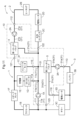
- FIG. 1 is a circuit configuration diagram of a cooling system having a cooling module according to a first embodiment.
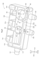
- FIG. FIG. 2 is a perspective view of the cooling module.
- FIG. 2 is an exploded perspective view of the cooling module.
- FIG. 2 is a perspective view of the first housing viewed from the joint surface side.
- FIG. 2 is an exploded perspective view of the cooling module.
- FIG. 2 is a perspective view of the first valve body of the first rotary valve.
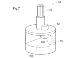
- FIG. 2 is a perspective view of the second valve body of the second rotary valve. is a sectional view taken along the line VIII-VIII in FIG. 3.
- FIG. 2 is a perspective view of the lower housing viewed from the joint surface side. 2 is a sectional view taken along the line XX in FIG. 2.
- FIG. 2 is a diagram showing the operation of the cooling system.
- FIG. 2 is a perspective view of a valve body of a rotary valve in a cooling module according to a second embodiment.
- FIG. 2 is a partially enlarged sectional view of the cooling module.
- FIG. 2 is a cross-sectional view showing the flow of cooling water when the valve body is in the first position.
- FIG. 2 is a cross-sectional view showing the flow of cooling water when the valve body is in the second position.
- FIG. 2 is a cross-sectional view showing the flow of cooling water when the valve body is in the third position.
- FIG. 2 is a perspective view of a cooling module according to a third embodiment.
- FIG. 2 is an exploded perspective view of the cooling module.
- FIG. 3 is a perspective view of a cooling module according to a fourth embodiment. is a sectional view taken along the line XXII-XXII in FIG. 21.
- the cooling system A including the cooling module valve according to the first embodiment includes a first water pump 1A, a radiator 1B, an inverter/motor 1C, a DC-DC converter 1D, a charger 1E, and a reserve.
- the first water pump 1A, the second water pump 2A, the third water pump 3A, the first rotary valve 4, and the second rotary valve 5 are attached to the cooling module 10.
- the radiator 1B, inverter/motor 1C, DC-DC converter 1D, charger 1E, reserve tank 1F, heater core 2B, electric heater 2D, water cooling capacitor 2C, battery 3B, chiller 3C, and electric heater 3D are connected to the cooling module 10.
- the cooling water is configured to flow between the cooling module 10 and the cooling module 10 via a plurality of channels.
- Cooling system A is suitable for use in automobiles equipped with a motor as a driving source, such as hybrid electric vehicles (HEVs), plug-in hybrid electric vehicles (PHEVs), and battery electric vehicles (BEVs). It is used in fuel cell electric vehicles (FCEVs) and the like (hereinafter collectively referred to as "electric vehicles”), and cools the inverter/motor 1C, battery 3B, etc. by circulating cooling water.
- HEVs hybrid electric vehicles
- PHEVs plug-in hybrid electric vehicles
- BEVs battery electric vehicles
- FCEVs fuel cell electric vehicles
- electric vehicles fuel cell electric vehicles
- the radiator 1B cools high temperature cooling water.
- the inverter/motor 1C is a travel drive source that operates with electric power supplied from the battery 3B.
- the DC-DC converter 1D and charger 1E charge the battery 3B.
- the heater core 2B heats the air with high-temperature cooling water to heat the interior of the vehicle. Electric heaters 2D and 3D heat the cooling water when the temperature is low.
- the water-cooled condenser 2C and chiller 3C cool the water when the temperature of the cooling water is high. Battery 3B supplies power to inverter/motor 1C.
- the first water pump 1A pumps cooling water to be supplied to the inverter/motor 1C, DC-DC converter 1D, and charger 1E.
- the second water pump 2A pumps cooling water to be supplied to the heater core 2B, electric heater 2D, and water-cooled condenser 2C.
- the third water pump 3A pumps cooling water to be supplied to the battery 3B, chiller 3C, and electric heater 3D.
- the first water pump 1A, the second water pump 2A, and the third water pump 3A control the flow of the cooling water flowing through the plurality of channels by pumping the cooling water.
- a circulating flow path configured to return to the radiator 1B from the radiator 1B through the first water pump 1A, the inverter/motor 1C, the DC-DC converter 1D, the charger 1E, and the reserve tank 1F
- the first circulation path 1 is referred to as a circulation path 1 (see FIG. 11), and the flow path formed inside the cooling module 10 is referred to as a first flow path 11.
- a circulating flow path configured to return to the heater core 2B from the heater core 2B through the second water pump 2A, the water-cooled condenser 2C, and the electric heater 2D is referred to as a second circulation path 2 (see FIG.
- a flow path formed in the cooling module 10 is referred to as a second flow path 21.
- a circulating flow path configured to return to the battery 3B from the battery 3B through the third water pump 3A, chiller 3C, and electric heater 3D is referred to as the third circulation path 3 (see FIG. 11).
- the flow path formed within the cooling module 10 is referred to as a third flow path 31.
- a communication channel 51 (an example of a channel and an outflow channel) that communicates the first channel 11, the second channel 21, and the third channel 31 is formed.
- the cooling module 10 includes a first water pump 1A, a second water pump 2A, a third water pump 3A, a first rotary valve 4, and a third water pump in the cooling system A. It is configured to include two rotary valves 5 and a manifold 100 in which a flow path is formed to allow cooling water to flow through these two rotary valves.
- the manifold 100 is formed by joining and integrating a plurality of housings, and thereby spans at least two housings (in this embodiment, a first housing 110 and a second housing 120, which will be described later) to provide cooling. It has a plurality of flow channels that allow water to flow through it. Note that, as shown in FIG. 1, the cooling module 10 does not have a reserve tank inside. Since the cooling module 10 does not have a reserve tank, the cooling module 10 can be configured compactly, and the degree of freedom in the arrangement of the cooling module 10 can be increased.
- the manifold 100 is formed by joining and integrating a first housing 110 (an example of a resin housing) and a second housing 120 (an example of a resin housing), both of which are made of resin, by a method such as vibration welding.
- the manifold 100 has a generally rectangular parallelepiped shape as a whole, and as shown in FIGS. 3 and 4, the joint surface 105 between the first housing 110 and the second housing 120 is planar.
- a direction parallel to the longitudinal direction of the joint surface 105 is defined as an X direction
- a direction parallel to the short direction of the joint surface 105 is defined as a Y direction
- a direction perpendicular to the joint surface 105 is defined as a Z direction.
- the joint surface 105 is parallel to the XY plane.
- the direction from the first water pump 1A to the third water pump 3A is defined as the X1 direction, and the opposite direction is defined as the X2 direction.
- the direction from the second outflow port 115 to the first inflow port 111 is defined as the Y1 direction, and the opposite direction is defined as the Y2 direction (the second outflow port 115 and the first inflow port 111 will be described later).
- the direction from the second housing 120 to the first housing 110 is defined as the Z1 direction, and the opposite direction is defined as the Z2 direction.
- the Z2 direction is the direction of gravity. That is, the first housing 110 is arranged vertically above the second housing 120.
- the first housing 110 includes a first inflow port 111, a second inflow port 112, a third inflow port 113, a first outflow port 114, a second outflow port 115, and a second outflow port 115.
- Five outflow ports 116 are formed.
- the second housing 120 is formed with a third outflow port 121, a fourth outflow port 122, and a sixth outflow port 123.
- the first inflow port 111, the second inflow port 112, the third inflow port 113, the first outflow port 114, the second outflow port 115, the third outflow port 121, the fourth outflow port 122, the fifth outflow port 116, and the All six outflow ports 123 have a cylindrical shape.
- the first inflow port 111, the second inflow port 112, and the third inflow port 113 are arranged in parallel so that their respective axes are along the Z direction and on the same plane, and all ports are aligned in the Z1 direction. It has an opening towards the end.
- the first outflow port 114 and the third outflow port 121 are arranged side by side so that their respective axes are along the X direction and on the same plane, and both ports have an opening toward the X2 direction.
- the second outflow port 115 and the fifth outflow port 116 are arranged side by side so that their respective axes are along the Y direction and on the same plane, and both ports have an opening toward the Y2 direction.
- the fourth outflow port 122 and the sixth outflow port 123 are also arranged side by side so that their respective axes are along the Y direction and on the same plane, and both ports have an opening toward the Y2 direction.
- the first inflow port 111, the first outflow port 114, and the second outflow port 115 are included in the first circulation path 1, and all communicate with the first flow path 11.
- the second inflow port 112 and the fourth outflow port 122 are included in the second circulation path 2 and both communicate with the second flow path 21 .
- the third inflow port 113, the fifth outflow port 116, and the sixth outflow port 123 are included in the third circulation path 3, and all communicate with the third flow path 31.
- the first rotary valve 4 and the second rotary valve 5 are connected to the first rotary valve 4 in the first housing 110 when the first housing 110 is viewed along the Z2 direction. It is attached between the inflow port 111, the second inflow port 112, the third inflow port 113, and the second outflow port 115 and the fifth outflow port 116.
- the first rotary valve 4 and the second rotary valve 5 what is exposed at the upper part of the first housing 110 is a valve that rotationally drives the first valve body 4A (an example of a valve body) of the first rotary valve 4.
- the first actuator 4B and the second actuator 5B rotate the second valve body 5A (an example of a valve body) of the second rotary valve 5.
- Both the first valve body 4A and the second valve body 5A are located within the second housing 120 (see FIG. 8). Thereby, the flow paths formed in the second housing 120 can be switched to control the flow of cooling water flowing through the plurality of flow paths.
- the first rotary valve 4 and the second rotary valve 5 are both electromagnetic valves whose flow paths are switched by an actuator, and the first valve body 4A and the second valve body 5A are rotated around an axis along the Z direction. By switching the flow paths, the flow of cooling water flowing through the plurality of flow paths is controlled.
- the first valve body 4A is a three-way valve
- the second valve body 5A is a four-way valve. Details will be described later.
- a first water pump 1A, a second water pump 2A, and a third water pump 3A are installed in the second housing 120 in this order along the X1 direction. It is being At this time, the first water pump 1A, the second water pump 2A, and the third water pump 3A are arranged so that their respective rotation axes are all along the Y direction.
- the second housing 120 includes a first downward sub-channel 11a that communicates with the first inflow port 111 and extends in the Z direction, and a downward sub-channel 11a that communicates with the second inflow port 112 and extends in the Z direction.
- the first water pump 1A pumps the cooling water that flows in from the first inflow port 111 through the first downward sub-flow path 11a.
- the second water pump 2A pumps the cooling water flowing from the second inflow port 112 through the second downward sub-flow path 21a.
- the third water pump 3A pumps the cooling water flowing from the third inflow port 113 through the third downward sub-flow path 31a.
- first downward sub-flow path 11a is a part of the first flow path 11
- second downward sub-flow path 21a is a part of the second flow path 21
- third downward sub-flow path 31a is a part of the first flow path 11. It is a part of the third flow path 31.
- the first water pump 1A, the second water pump 2A, and the third water pump 3A are attached to a mounting portion 125 formed at the end in the Z2 direction (lower end in the vertical direction) of the second housing 120. is attached to.
- the mounting portion 125 is thicker than other parts of the second housing 120. Thereby, even if the second housing 120 is made of resin, it can ensure the strength to attach and hold the heavy first water pump 1A, second water pump 2A, and third water pump 3A.
- the mounting portion 125 includes a first vortex chamber 1Aa in which cooling water that has flowed into the first water pump 1A from the first sub-flow path 11a in the downward direction is rotated after being discharged by rotation of an impeller (not shown);
- a second vortex chamber 2Aa rotates after the cooling water that has flowed into the second water pump 2A from the second sub-flow path 21a is discharged by rotation of the impeller, and a third water pump 3A from the downward third sub-flow path 31a.
- a third vortex chamber 3Aa is formed in which the cooling water that has flowed into the vortex swirls after being discharged by the rotation of the impeller.
- the first water pump 1A, the second water pump 2A, and the third water pump 3A does not require a shroud that regulates the direction of inflow and outflow of cooling water, making it possible to reduce the size, weight, and cost of the cooling module 10.
- the manifold 100 since the manifold 100 has a plurality of flow paths formed across the first housing 110 and the second housing 120, the number of piping can be reduced.
- the manifold 100 since the manifold 100 is constructed by joining the first housing 110 and the second housing 120, the shape and configuration of the flow path in the manifold 100 can be determined by considering the position and direction of the port for connecting the piping. Even if the configuration becomes complicated, the shapes of the first housing 110 and the second housing 120 can be simplified. Thereby, the piping connected to the port can be consolidated and redundant routing can be avoided, so that the length of the piping connected to the port can be shortened and simplified.
- the first rotary valve 4 includes a first valve body 4A, a first valve chamber 4C (an example of a valve chamber), and a first preliminary chamber 4D (an example of an inflow preliminary chamber and a preliminary chamber).
- the second rotary valve 5 includes a second valve body 5A, a second valve chamber 5C (an example of a valve chamber), a second preliminary chamber 5D (an example of an inflow preliminary chamber and a preliminary chamber), and a third preliminary chamber 5E (an example of an outflow preliminary chamber). and an example of a preliminary room) and a fourth preliminary room 5F (an example of an outflow preliminary room and a preliminary room).
- the first valve body 4A is entirely accommodated in the first valve chamber 4C.
- the first valve body 4A has a first shaft 42 that is rotated by the first actuator 4B and a first valve body 43 that rotates integrally with the first shaft 42.
- the first valve main body 43 has a cylindrical shape with walls on the top and bottom and side walls, and a first flow hole 43a, a second flow hole 43b, and a third flow hole 43c, which are through holes, are formed in the side wall 43d.
- the first communication hole 43a, the second communication hole 43b, and the third communication hole 43c are arranged adjacently at intervals of 90 degrees in the circumferential direction, and are connected to each other inside the first valve body 43.
- the first communication hole 43a, the second communication hole 43b, and the third communication hole 43c are all approximately rectangular and have the same opening area.
- the opening areas of the first communication hole 43a, the second communication hole 43b, and the third communication hole 43c are the same as those of the first communication hole 131 (an example of an inlet), the second communication hole 132, and the third communication hole 133, which will be described later. It is larger than the opening area (see Figure 8).
- the second valve body 5A is entirely accommodated in the second valve chamber 5C.
- the second valve body 5A has a second shaft 52 that is rotated by the second actuator 5B and a second valve body 53 that rotates integrally with the second shaft 52.
- the second valve main body 53 has a cylindrical shape, and a fourth communication hole 53a and a fifth communication hole 53b are formed in a side wall 53c.
- the fourth communication hole 53a and the fifth communication hole 53b are connected to each other inside the second valve body 53.
- the fourth communication hole 53a and the fifth communication hole 53b are arranged 180 degrees apart in the circumferential direction.
- Both the fourth communication hole 53a and the fifth communication hole 53b have a rectangular shape, and the fourth communication hole 53a has a larger opening area than the fifth communication hole 53b.
- the opening area of the fifth communication hole 53b is approximately the same as the opening area of each of the fifth communication hole 135 (an example of an outflow port), the sixth communication hole 136, and the seventh communication hole 137 (an example of an outflow port), which will be described later. It is.
- the fourth communication hole 53a has the fifth communication hole 53b, the fifth communication hole 135, the sixth communication hole 136, and the seventh communication hole 137.
- a fourth communication hole 134 (an example of an inlet), which will be described later, even when facing any of the above (see FIG. 8).
- the fourth communication hole 134, the fifth communication hole 135, the sixth communication hole 136, and the seventh communication hole 137 are aligned with the axis P of the fourth communication hole 134,
- the axis Q of the five communicating holes 135, the axis R of the sixth communicating hole 136, and the axis S of the seventh communicating hole 137 are all arranged on the same plane.
- FIGS. 3 and 8 to 10 the flow of cooling water in the cooling module 10 will be explained using FIGS. 3 and 8 to 10.
- the cooling water cooled by the radiator 1B enters the second housing 120 of the cooling module 10 from the first inflow port 111 and flows through the downward first sub-channel 11a in the Z2 direction. , flows into the first water pump 1A.
- the cooling water pumped by the first water pump 1A flows in the Z1 direction through the upward first sub-flow path 11b formed along the Z direction, and passes through the joint surface 105 between the first housing 110 and the second housing 120.
- the first horizontal sub-channel 11c branches from the first upper sub-channel 11b.
- the cooling water flowing in the Z1 direction from the second housing 120 to the first housing 110 through the first sub-flow passage 11b in the upward direction extends from the second housing 120 to the first housing 110. Thereafter, the flow direction is changed to the X2 direction and the fluid flows out from the first outflow port 114.
- the cooling water flowing out of the cooling module 10 from the first outflow port 114 cools the DC-DC converter 1D and the charger 1E, and flows back to the radiator 1B via the reserve tank 1F (see FIG. 1).
- the first lateral sub-flow path 11c is formed across the first housing 110 and the second housing 120, and is formed along the Y direction. That is, the first lateral sub-flow path 11c is formed along the joint surface 105 between the first housing 110 and the second housing 120, and the upper half of the first lateral sub-flow path 11c is formed between the first housing 110 and the second housing 120. The lower half is formed as a second housing 120.
- the first lateral sub-flow path 11c is formed by joining the first housing 110 and the second housing 120.
- the cooling water flows through the first horizontal sub-channel 11c in the Y2 direction, and flows out of the cooling module 10 from the second outflow port 115 provided at the downstream end of the first horizontal sub-channel 11c.
- the cooling water flowing out from the second outflow port 115 cools the inverter/motor 1C and returns to the radiator 1B via the reserve tank 1F (see FIG. 1). Note that the first upward sub-channel 11b and the first lateral sub-channel 11c constitute a part of the first channel 11.
- the cooling water cooled by the heater core 2B enters the second housing 120 of the cooling module 10 from the second inflow port 112 and flows in the downward second sub-channel 21a in the Z2 direction. , flows into the second water pump 2A.
- the cooling water pumped by the second water pump 2A flows in the Z1 direction through an upward second sub-channel 21b (an example of a channel and an inlet channel) formed along the Z direction.
- a first preliminary chamber 4D which is a space communicating with the second upper sub-channel 21b, is formed at the downstream end of the second upper sub-channel 21b.
- the first preliminary chamber 4D is arranged adjacent to the first valve chamber 4C of the first rotary valve 4 in the Y1 direction.
- the first preliminary chamber 4D has a first communication hole 131 opened along the Y direction, and communicates with the first valve chamber 4C via the first communication hole 131.
- the direction of flow of cooling water flowing in the Z1 direction through the upward second sub-flow path 21b is changed to the Y2 direction, and the cooling water flows from the first communication hole 131 into the first valve chamber 4C. It can be distributed. That is, the upward second sub-channel 21b is arranged so as not to overlap the first communication hole 131 in a side view (viewed parallel to the XY plane).
- first valve chamber 4C and the first preliminary chamber 4D are formed astride the second housing 120 and the first housing 110. Thereby, the degree of freedom in the shape (size, height) of the first preliminary chamber 4D can be increased, and the degree of freedom in routing the second upward sub-flow path 21b can be increased.
- the first valve chamber 4C houses the first valve body 4A rotatably about a first shaft 42 along the Z direction. All of the cooling water flowing through the second upward sub-flow path 21b flows into the first valve chamber 4C via the first preliminary chamber 4D and the first communication hole 131.
- the first valve chamber 4C communicates with the lateral second sub flow path 21c (an example of a flow path) via a second communication hole 132 opened along the Y direction, and the first valve chamber 4C communicates with the second horizontal sub flow path 21c (an example of a flow path). It communicates with the fourth flow path 41 via the three communication holes 133.
- the lateral second sub-flow path 21c extends along the Y direction
- the fourth flow path 41 extends along the X direction, both of which are formed within the second housing 120 (see FIG. 3).
- the second downward sub-channel 21a, the second upward sub-channel 21b, the second horizontal sub-channel 21c, the first valve chamber 4C, and the first preliminary chamber 4D are part of the second channel 21.
- the fourth flow path 41 is not a part of the second flow path 21 and does not constitute the second circulation path 2.
- the third communication hole 43c of the first valve body 4A faces the first communication hole 131
- the first communication hole 43a faces the second communication hole 132
- the third communication hole 133 is closed facing the side wall 43d. From this, the cooling water that has flowed into the first valve chamber 4C flows into the second horizontal sub-flow path 21c (the state of the second circulation path 2 in FIG. 11).
- the second flow hole 43b is aligned with the first valve body 43.
- the third communication hole 43c faces the communication hole 131, and the third communication hole 43c faces the third communication hole 133, while the second communication hole 132 faces the side wall 43d and is closed. From this, the cooling water that has flowed into the first valve chamber 4C flows into the fourth flow path 41. In this way, the first rotary valve 4 allows the cooling water that flows through the second upward sub-flow path 21b formed in the cooling module 10 and flows into the first valve chamber 4C via the first preliminary chamber 4D. The outflow path is switched to the lateral second sub-flow path 21c and the fourth flow path 41.
- the cooling water that has flowed from the first valve chamber 4C into the second lateral sub-flow path 21c via the second communication hole 132 flows in the Y2 direction and flows out of the fourth outflow port 122 to the outside of the cooling module 10.
- the cooling water flowing out from the fourth outflow port 122 flows back to the heater core 2B via the water cooling capacitor 2C and the electric heater 2D (see FIG. 1).
- the cooling water that has flowed into the fourth flow path 41 from the first valve chamber 4C via the third communication hole 133 flows in the X2 direction and flows out of the cooling module 10 from the third outflow port 121.
- the cooling water flowing out from the second outflow port 115 flows into the radiator 1B via the reserve tank 1F (see FIG. 1).
- the first rotary valve 4 By rotating the first valve body 4A around the axis along the Z direction by the first actuator 4B, the first rotary valve 4 flows through the second sub-channel 21b in the upward direction and into the first valve chamber 4C.
- the cooling water that has flowed into the sub-channel 21c is switched between the second horizontal sub-channel 21c and the fourth channel 41 to flow therethrough.
- the cooling water that has cooled the battery 3B enters the second housing 120 of the cooling module 10 from the third inflow port 113 and flows through the downward third sub-channel 31a in the Z2 direction. It flows into the third water pump 3A.
- the cooling water pumped by the third water pump 3A flows in the Z1 direction through an upward third sub-flow path 31b (an example of a flow path and an inflow path) formed along the Z direction.
- a second preliminary chamber 5D which is a space communicating with the third upper sub-channel 31b, is formed at the downstream end of the third upper sub-channel 31b.
- the second preliminary chamber 5D is arranged adjacent to the second valve chamber 5C (an example of a valve chamber) of the second rotary valve 5 in the Y1 direction.
- the second preliminary chamber 5D has a fourth communication hole 134 opened along the Y direction, and communicates with the second valve chamber 5C via the fourth communication hole 134.
- second valve chamber 5C and the second preliminary chamber 5D are formed across the second housing 120 and the first housing 110. This increases the degree of freedom in the shape (size, height) of the second preliminary chamber 5D, and increases the degree of freedom in routing the third upward sub-flow path 31b.
- the second valve chamber 5C houses the second valve body 5A rotatably about the second shaft 52 along the Z direction. All of the cooling water flowing through the third upward sub-flow path 31b flows into the second valve chamber 5C via the second preliminary chamber 5D and the fourth communication hole 134.
- the second valve chamber 5C has a sixth communication hole 136 opened along the Y direction, and communicates with the third horizontal sub-flow path 31d via the sixth communication hole 136.
- the second valve chamber 5C also includes a fifth communication hole 135 (an example of an outflow port) and a seventh communication hole 137 (an example of an outflow port) that are opened adjacent to both sides in the circumferential direction with the sixth communication hole 136 in between.
- the third preliminary chamber 5E and the fourth preliminary chamber 5F are formed astride the second housing 120 and the first housing 110. This increases the degree of freedom in the shape (size, height) of the third auxiliary chamber 5E and the fourth auxiliary chamber 5F, and increases the degree of freedom in routing the L-shaped third sub-channel 31c and the communication channel 51. be able to.
- the fourth communication hole 53a of the second valve body 5A faces the fourth communication hole 134
- the fifth communication hole 53b faces the fifth communication hole 135, and the sixth communication hole 136
- the seventh communication hole 137 is closed facing the side wall 53c.
- the cooling water that has flowed into the second valve chamber 5C flows into the third preliminary chamber 5E. That is, the cooling water that has flowed into the second valve chamber 5C flows into an L-shaped third sub-flow path 31c (an example of a flow path and an outflow path), which will be described later.
- the fourth communication hole 53a becomes the fourth communication hole.
- the second rotary valve 5 receives the cooling water that flows through the upward third sub-flow path 31b formed in the cooling module 10 and flows into the second valve chamber 5C via the second preliminary chamber 5D.
- the outflow path is switched to the third auxiliary chamber 5E (L-shaped third sub-channel 31c), the lateral third sub-channel 31d, and the fourth auxiliary chamber 5F (communication channel 51).
- the third preliminary chamber 5E communicates with the fifth outflow port 116 via an L-shaped third sub-channel 31c extending along the Z direction.
- the flow direction of cooling water flowing from the second valve chamber 5C through the fifth communication hole 135 into the third auxiliary chamber 5E in a direction perpendicular to the Z direction can be changed to the Z1 direction.
- the L-shaped third sub-flow path 31c can be made to flow through the third sub-channel 31c so that the liquid can flow out from the fifth outflow port 116 to the outside of the cooling module 10. That is, the L-shaped third sub-channel 31c is arranged so as not to overlap the fifth communication hole 135 when viewed from the side.
- the cooling water flowing out from the fifth outflow port 116 flows back to the battery 3B via the electric heater 3D (see FIG. 1).
- the cooling water that has flowed from the second valve chamber 5C into the third horizontal sub-flow path 31d via the sixth communication hole 136 flows in the Y2 direction and flows out of the sixth outflow port 123 to the outside of the cooling module 10.
- the cooling water flowing out from the sixth outflow port 123 flows back to the battery 3B via the chiller 3C (see FIG. 1).
- the third preliminary chamber 5E constitute a part of the third flow path 31.
- the fourth preliminary chamber 5F communicates with a communication channel 51 that extends from the fourth preliminary chamber 5F in the Z direction and then bends and extends in the X direction. That is, the communication channel 51 is arranged so as not to overlap the seventh communication hole 137 in a side view.
- a first portion 51a of the communication channel 51 extending in the Z direction is formed in the second housing 120, and a second portion 51b extending in the X direction is formed astride the first housing 110 and the second housing 120. has been done. That is, the second portion 51b of the communication channel 51 is formed along the joint surface 105 between the first housing 110 and the second housing 120, and the upper half of the second portion 51b is formed in the first housing 110. , the lower half is formed in the second housing 120.
- the communication flow path 51 is not a part of the third flow path 31 and does not constitute the third circulation path 3.
- the communication channel 51 connects the first channel 11, the second channel 21, and the third channel 31 within the cooling module 10.
- the communication flow path 51 By providing the communication flow path 51 in this way, the three circulation paths through which the cooling water circulates can be consolidated, so the number of piping connected to the port can be reduced, and the length of the piping can be shortened. It can be simplified.
- the second portion 51b of the communication channel 51 communicates with the first horizontal sub-channel 11c at the end opposite to the fourth preliminary chamber 5F. Moreover, the second portion 51b intersects with the lateral second sub-flow path 21c when viewed along the Z direction. The second portion 51b is recessed in the Z2 direction and communicates with the lateral second sub-channel 21c at the intersection.
- the second rotary valve 5 is caused to flow into the second valve chamber 5C from the upward third sub-channel 31b by rotating the second valve body 5A around the axis along the Z direction by the second actuator 5B.
- the cooling water (1) is caused to flow through the third preparatory chamber 5E and the L-shaped third sub-channel 31c through the fifth communication hole 135 and flow out from the fifth outflow port 116; (2) the seventh communication hole 137 (3) from the seventh communication hole 137 to the fourth auxiliary chamber 5F and the communication channel 51 and flow out from the second outflow port 115.
- the fluid flows through the passage 21c to flow out from the second outflow port 115 and the fourth outflow port 122, and flows through the third lateral sub-flow channel 31d through the sixth communication hole 136 to flow out from the sixth outflow port 123. , and distribute it in three ways.
- the L-shaped third sub-channel 31c is arranged so as not to overlap with the fifth communication hole 135, and the communication channel 51 is arranged so as not to overlap with the seventh communication hole 137.
- a rotary valve 6 (an example of a cooling module valve) according to a second embodiment will be described using the drawings.
- the rotary valve 6 of this embodiment is used in the cooling module 20.
- the cooling module 20 differs from the cooling module 10 according to the above embodiment in the flow path configuration.
- the rotary valve 6 includes a valve body 6A, a valve chamber 6C, a first preliminary chamber 6D (an example of an inflow preliminary chamber and a preliminary chamber), and a second preliminary chamber 6E (an example of an inflow preliminary chamber and a preliminary chamber). (an example of a preliminary room), a third preliminary room 6F (an example of an outflow preliminary room and a preliminary room), and a fourth preliminary room 6G (an example of an outflow preliminary chamber and a preliminary chamber).
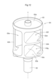
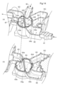
- the valve body 6A is entirely housed in the valve chamber 6C. As shown in FIG.
- the valve body 6A includes a shaft 62 that rotates around a rotation axis T by an actuator 6B and a valve body 63 that rotates integrally with the shaft 62.
- the valve body 63 includes two discs 63a and 63b arranged vertically apart, and a connecting plate that includes the rotation axis T of the shaft 62 and is arranged to connect the two discs 63a and 63b.
- 63c, a semicircular partition plate 63d arranged perpendicularly to the connecting plate 63c at the center of the connecting plate 63c, and two support columns connecting the two discs 63a and 63b.
- a first valve space 63e (an example of a valve space) is formed by the two discs 63a, 63b and the connecting plate 63c
- a second valve space 63f (an example of a valve space) is formed by the disc 63a, the connecting plate 63c, and the partition plate 63d
- a third valve space 63g (an example of a valve space) is formed by the disk 63b, the connecting plate 63c, and the partition plate 63d. That is, the connection plate 63c divides the space into a plurality (in this embodiment, two) of spaces (a space in which the first valve space 63e, the second valve space 63f, and the third valve space 63g are integrated) in the circumferential direction. ing.
- At least one of the spaces is further divided into a plurality of (in this embodiment, two) spaces (a second valve space 63f and a third valve space 63g) in the direction along the rotation axis T by a partition plate 63d. ing.
- the first valve space 63e, the second valve space 63f, and the third valve space 63g are divided by the disks 63a, 63b, the connecting plate 63c, and the partition plate 63d. and do not communicate with each other.
- the manifold of the cooling module 20 is formed by joining and integrating a first housing 70 (an example of a resin housing) and a second housing 80 (an example of a resin housing), both of which are made of resin, by a method such as vibration welding.
- a valve chamber 6C is arranged in the second housing 80, and adjacent to the periphery of the valve chamber 6C are a first preliminary chamber 6D, a second preliminary chamber 6E, a third preliminary chamber 6F, a fourth preliminary chamber 6G, and a fourth preliminary chamber 6C.
- Five preliminary rooms 6H are arranged.
- the first preliminary chamber 6D, the second preliminary chamber 6E, the third preliminary chamber 6F, the fourth preliminary chamber 6G, and the fifth preliminary chamber 6H are formed astride the second housing 80 and the first housing 70. This increases the degree of freedom in the shape (size, height) of each preparatory chamber, and increases the degree of freedom in routing the inlet and outlet channels, which will be described later.
- the direction parallel to the cut plane shown in FIG. 13 and perpendicular to the axis 62 is defined as the X direction
- the direction perpendicular to the cut plane is defined as the Y direction
- the direction parallel to the axis 62 is defined as the Z direction.
- the direction from the valve body 6A toward the fifth preliminary chamber 6H is defined as the X1 direction
- the opposite direction is defined as the X2 direction.
- the direction from the valve body 6A toward a third inflow path 82 which will be described later, is defined as the Y2 direction
- the opposite direction is defined as the Y1 direction.
- the direction from the second housing 80 to the first housing 70 is defined as the Z1 direction, and the opposite direction is defined as the Z2 direction.
- the Z2 direction is the direction of gravity. That is, the first housing 70 is arranged above the second housing 80 in the vertical direction.
- the first preliminary chamber 6D is connected to a first inflow path 71 (an example of a flow path and an inflow path) formed in the first housing 70 and into which cooling water flows.
- the second preliminary chamber 6E is formed in the second housing 80 and is connected to a second inflow path 81 (an example of a flow path and an inflow path) through which cooling water flows through a seventh communication hole 64g (an example of an inflow port).
- the third preliminary chamber 6F is formed across the first housing 70 and the second housing 80, and includes a first outflow path 72 (an example of a flow path and an outflow path) through which cooling water flows out and an eighth communication hole 64h (outflow port). example).
- the fourth preliminary chamber 6G is formed in the first housing 70 and is connected to a second outflow path 73 (an example of a flow path and an outflow path) through which cooling water flows out.
- the fifth preliminary chamber H is formed in the second housing 80 and is connected to a third outflow path 74 (an example of a flow path and an outflow path) through which cooling water flows out through a ninth communication hole 64i (an example of an outflow port).
- the valve body 6A is formed in the second housing 80 and is connected to a third inflow path 82 (an example of a flow path) into which cooling water flows. No preliminary chamber is formed between the third inflow path 82 and the valve body 6A.
- the valve body 6A and the first preliminary chamber 6D communicate with each other via a first communication hole 64a (an example of an inlet) formed in the valve chamber 6C.
- the valve body 6A and the second preliminary chamber 6E communicate with each other via a second communication hole 64b (an example of an inlet) formed in the valve chamber 6C.
- the valve body 6A and the third preliminary chamber 6F communicate with each other via a third communication hole 64c (an example of an outflow port) formed in the valve chamber 6C.
- the valve body 6A and the fourth preliminary chamber 6G communicate with each other via a fourth communication hole 64d (an example of an outflow port) formed in the valve chamber 6C.
- the valve body 6A and the fifth preliminary chamber 6H communicate with each other via a fifth communication hole 64e (an example of an outflow port) formed in the valve chamber 6C.
- the valve body 6A and the third inflow path 82 communicate with each other via a sixth communication hole 64f formed in the valve chamber 6C.
- the first communication hole 64a, the second communication hole 64b, and the fourth communication hole 64d are located in the Z2 direction from the partition plate 63d in the valve body 6A and in a side view (viewed parallel to the XY plane) of the third valve.
- the respective axes (not shown) of the first communication hole 64a, the second communication hole 64b, and the fourth communication hole 64d are on the same plane.
- the third communication hole 64c, the fifth communication hole 64e, and the sixth communication hole 64f are arranged in the valve body 6A in the Z1 direction relative to the partition plate 63d and at a position overlapping with the second valve space 63f in a side view.
- the respective axes (not shown) of the third communication hole 64c, the fifth communication hole 64e, and the sixth communication hole 64f are on the same plane.
- the inflow and outflow ports can be arranged at two different heights, compared to a rotary valve that has multiple inflow and outflow ports arranged at different heights. Therefore, the height of the rotary valve 6 can be reduced, and the cooling module 20 can be downsized.
- the first communicating hole 64a and the third communicating hole 64c have different height positions, and communicate with each other via the first valve space 63e of the valve body 6A disposed in the valve chamber 6C.
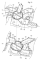
- FIGS. 14 to 16 are cross-sectional views taken along the line aa in FIG. 13, and (b) are cross-sectional views taken along the line b-b of FIG. 13.
- the first valve space 63e of the valve body 6A faces the first preliminary chamber 6D and the third preliminary chamber 6F
- the second valve space 63f of the valve body 6A faces the third preliminary chamber 6D
- the third valve space 63g of the valve body 6A faces the second preliminary chamber 6E and the fourth preliminary chamber 6G.
- the cooling water that has flowed into the first preliminary chamber 6D from the first inflow path 71 flows into the third preliminary chamber 6F via the first communication hole 64a, the first valve space 63e, and the third communication hole 64c. , flows out into the first outflow path 72 (see also FIG. 13).
- the cooling water that has flowed into the third inflow path 82 flows into the fifth preliminary chamber 6H via the sixth communication hole 64f, the second valve space 63f, and the fifth communication hole 64e, and flows out into the third outflow path 74 ( (See also Figure 13).
- the cooling water that has flowed into the second preliminary chamber 6E from the second inflow path 81 flows into the fourth preliminary chamber 6G via the second communication hole 64b, the third valve space 63g, and the fourth communication hole 64d, and then flows into the fourth preliminary chamber 6G through the second communication hole 64b, the third valve space 63g, and the fourth communication hole 64d. 73 (see also FIG. 13).
- the first valve space 63e of the valve body 6A faces the second preliminary chamber 6E and the third preliminary chamber 6F
- the second valve space 63f of the valve body 6A faces the third preliminary chamber 6E
- the third valve space 63g of the valve body 6A faces the first preparatory chamber 6D and the fourth preparatory chamber 6G.
- the cooling water that has flowed into the second preliminary chamber 6E from the second inflow path 81 flows into the third preliminary chamber 6F via the second communication hole 64b, the first valve space 63e, and the third communication hole 64c, It flows out into the first outflow path 72 (see also FIG. 13).
- the cooling water that has flowed into the third inflow path 82 flows into the fifth preliminary chamber 6H via the sixth communication hole 64f, the second valve space 63f, and the fifth communication hole 64e, and flows out into the third outflow path 74 ( (See also Figure 13).
- the cooling water that has flowed into the first preliminary chamber 6D from the first inflow path 71 flows into the fourth preliminary chamber 6G via the first communication hole 64a, the third valve space 63g, and the fourth communication hole 64d, and then flows into the fourth preliminary chamber 6G through the first communication hole 64a, the third valve space 63g, and the fourth communication hole 64d. It flows out into the outflow path 73 (see also FIG. 13).
- the first valve space 63e of the valve body 6A faces the second preliminary chamber 6E and the fifth preliminary chamber 6H
- the second valve space 63f of the valve body 6A faces the third inlet.
- the third valve space 63g of the valve body 6A faces the first preparatory chamber 6D and the fourth preparatory chamber 6G.
- the cooling water that has flowed into the second preliminary chamber 6E from the second inflow path 81 flows into the fifth preliminary chamber 6H via the second communication hole 64b, the first valve space 63e, and the fifth communication hole 64e, It flows out into the third outflow path 74 (see also FIG. 13).
- the cooling water that has flowed into the third inflow path 82 flows into the third preliminary chamber 6F via the sixth communication hole 64f, the second valve space 63f, and the third communication hole 64c, and flows out into the first outflow path 72 (see FIG. (See also 13).
- the cooling water that has flowed into the first preliminary chamber 6D from the first inflow path 71 flows into the fourth preliminary chamber 6G via the first communication hole 64a, the third valve space 63g, and the fourth communication hole 64d, and then flows into the fourth preliminary chamber 6G through the first communication hole 64a, the third valve space 63g, and the fourth communication hole 64d. It flows out into the outflow path 73 (see also FIG. 13).
- the first preliminary chamber 6D is provided, even if the first inflow path 71 is arranged above the rotary valve 6 (in the Z1 direction) and extends along the Z direction, the flow The cooling water can be caused to flow into the valve chamber 6C by changing the direction by 90 degrees.
- the third preliminary chamber 6F is provided, even if the first outflow path 72 is arranged above and apart from the rotary valve 6 and extends along the X direction, the cooling water flowing out from the valve chamber 6C Cooling water can be made to flow through the first outflow path 72 by changing the height in the Z direction.
- the fourth auxiliary chamber 6G is provided, even if the second outflow path 73 is arranged above and apart from the rotary valve 6 and extends along the Z direction, the cooling that has flowed out from the valve chamber 6C Cooling water can be made to flow through the second outflow path 73 by changing the height and direction of the water in the Z direction. Furthermore, since the fifth auxiliary chamber 6H is provided, even if the third outflow path 74 is arranged above and apart from the rotary valve 6 and extends along the X direction, the cooling that flows out from the valve chamber 6C Cooling water can be made to flow through the third outflow path 74 by changing the height of the water in the Z direction.
- the arrangement of the inflow path and the outflow path is not restricted by the height (length along the Z direction) of the rotary valve 6. Further, since the heights of the inflow path and the inlet and/or the heights of the outflow path and the outflow port can be made different, the degree of freedom in routing the inflow path and the outflow path can be increased.
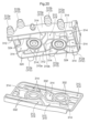
- FIGS. 17 to 20 a cooling module 300 using a first rotary valve 340 (an example of a cooling module valve) and a second rotary valve 350 (an example of a cooling module valve) according to the third embodiment will be described using FIGS. 17 to 20. I will explain.
- the cooling module 300 of this embodiment is different from the cooling modules 10 and 20 according to each of the embodiments described above in the flow path configuration.
- the cooling module 300 includes a first rotary valve 340, a second rotary valve 350, a first water pump 360 (an example of a water pump), and a second water pump 370. (an example of a water pump) and a manifold 302 in which a plurality of flow paths 312 (an example of an inflow path and an outflow path) (see FIG. 19) are formed to allow cooling water to flow therethrough.
- the manifold 302 is formed by joining and integrating a plurality of housings, and in this embodiment, as shown in FIG. 20, it is formed by joining a first housing 310 and a second housing 330. ing.
- the plurality of flow paths 312 shown in FIG. 19 include an inlet path that allows cooling water to flow into the first rotary valve 340 or the second rotary valve 350, and an inlet path that allows the cooling water to flow out from the first rotary valve 340 or the second rotary valve 350.
- This concept includes both outflow channels.
- the plurality of flow paths 312 include a flow path formed only in the first housing 310, a flow path formed only in the second housing 330, and a flow path formed spanning from the first housing 310 to the second housing 330.
- This concept includes all channels through which cooling water flows inside the manifold 302, such as channels that flow inside the manifold 302.
- the flow path 312 having a portion protruding outward from the outer wall 310a of the first housing 310 is connected to the second housing 330 in a direction along the rotation axis AX of the first rotary valve 340.
- a plurality (five in this embodiment) are arranged on the side closer to the second housing 330, and a plurality (four in this embodiment) are arranged on the side far from the second housing 330.
- the five channels 312 whose entire external appearance of the protruding portions are depicted are the channels 312 on the side closer to the second housing 330.
- the four channels 312 whose protruding portions are depicted in cross section are the channels 312 on the side far from the second housing 330.
- the central axes of these nine channels 312 along the protruding direction are all perpendicular to the rotation axis AX (see FIG. 18).
- the five flow paths 312 located closer to the second housing 330 pass through the central axis CX of the protruding portion of any one of the flow paths 312 and extend toward the rotation axis AX. It intersects with the vertical virtual plane P1 (see FIG. 17).
- a set of five channels 312 having such a positional relationship is referred to as a first channel group 312a.
- the four channels 312 other than the five channels 312 of the first channel group 312a are imaginary that passes through the central axis DX of the protruding portion of any one of the channels 312 and is perpendicular to the rotation axis AX. It intersects plane P2 (see FIG. 17).
- a set of four channels 312 having such a positional relationship is referred to as a second channel group 312b. That is, the second channel group 312b is arranged offset from the first channel group 312a in the direction along the rotation axis AX.
- At least one channel 312 of the first channel group 312a and the second channel group 312b has a first communicating hole 316a (an example of an inlet or an outlet) and a second communicating hole 316a (an example of an inlet or an outlet). It communicates with the first valve chamber 316 (an example of a valve chamber) via a hole 316b (an example of an inlet or an outlet).
- the axial center (not shown) of the first communication hole 316a and the axial center (not shown) of the second communication hole 316b have different height positions in the direction along the rotation axis AX.
- the first rotary valve 340, the second rotary valve 350, the first water pump 360, and the second water pump 370 are all attached to the first housing 310. installed.
- the first rotary valve 340 and the first water pump 360 are arranged next to each other, and the second rotary valve 350 and the second water pump 370 are arranged next to each other.
- the rotation axis AX of the first rotary valve 340 and the rotation axis AX of the second rotary valve 350 are parallel, and the rotation axis BX of the first water pump 360 and the rotation axis BX of the second water pump 370 are parallel.
- the rotation axes AX of the first rotary valve 340 and the second rotary valve 350 and the rotation axes BX of the first water pump 360 and the second water pump 370 are perpendicular to each other. Only some of the plurality of channels 312 are formed in the second housing 330 (see FIG. 20).
- the first rotary valve 340 includes a first actuator 341, a first valve body 342 (an example of a valve body), a first valve chamber 316, and a plurality of preliminary chambers 314 (inflow reserve) formed around the first valve chamber 316. (an example of a room or an outflow preliminary room).
- the second rotary valve 350 includes a second actuator 351, a second valve body 352 (an example of a valve body), a second valve chamber 318 (an example of a valve chamber), and a plurality of valve bodies formed around the second valve chamber 318. It has a spare room 314. Among these, the first valve chamber 316, the second valve chamber 318, and the preliminary chamber 314 are formed in the first housing 310.
- the first valve chamber 316 and the second valve chamber 318 accommodate the entirety of the first valve body 342 and the second valve body 352, respectively.
- the first valve chamber 316 and the second valve chamber 318 are formed in the first housing 310 and are located at the center between the pair of opposing outer walls 310a and between the first water pump 360 and the second water pump 370. It is arranged in region 310b.
- the first actuator 341 and the second actuator 351 are exposed on the surface of the first housing 310.
- the first valve body 342 is partitioned into a plurality of (two in this embodiment) spaces in the circumferential direction by a connecting plate 342a, and at least one of them is divided into a plurality of spaces (two in this embodiment).
- the two (one in this embodiment) space is further divided into a plurality of (two in this embodiment) spaces in the direction along the rotation axis AX by the partition plate 342b.
- a space partitioned by the connecting plate 342a and without the partition plate 342b inside is called a first valve space 342c
- a space partitioned by the connecting plate 342a and the partition plate 342b is called a second valve space 342d and a third valve space 342e.
- the second valve body 352 is also divided into three valve spaces.
- the first communication hole 316a and the second communication hole 316b communicate with each other when facing the first valve space 342c of the first valve body 342, and when there is a partition plate 342b between them, the first communication hole 316a and the second communication hole 316b communicate with each other. It faces either the second valve space 342d or the third valve space 342e, and does not communicate with each other.
- a plurality of auxiliary chambers 314 are formed between the flow path 312 and the first valve chamber 316 and between the flow path 312 and the second valve chamber 318, and are connected to the flow path 312 and the first valve chamber 316 via the auxiliary chamber 314.
- the flow path 312 and the second valve chamber 318 are in communication with each other.
- the concept of the preliminary chamber 314 includes both an inflow preliminary chamber connected to the inflow path and an outflow preliminary chamber connected to the outflow path.
- the preliminary chamber 314 is arranged in all the flow paths 312 communicating with the first valve chamber 316 and in all the flow paths 312 communicating with the second valve chamber 318.
- the plurality of flow paths 312 and the plurality of preliminary chambers 314 are arranged radially to surround each of the first valve chamber 316 and the second valve chamber 318.
- the first housing 310 includes a flow passage 312, a first valve chamber 316, a second valve chamber 318, a preliminary chamber 314, a first vortex chamber 320, and a second vortex chamber 322, which are adjacent to each other.
- a first partition wall 324 (an example of a partition wall) is formed to partition two parts.
- the first housing 310 is composed only of a flow path 312, a first valve chamber 316, a second valve chamber 318, a preliminary chamber 314, a first vortex chamber 320, a second vortex chamber 322, and a first partition wall 324.
- a second partition wall 332 (an example of a partition wall) is formed in the second housing 330 to partition a portion of the plurality of channels 312 formed in the second housing 330 and two adjacent ones of the preliminary chambers 314. ing.
- the manifold 302 is formed by joining the first partition wall 324 of the first housing 310 and the second partition wall 332 of the second housing 330.
- FIGS. 21 and 22 a cooling module 400 using a first rotary valve 440 (an example of a cooling module valve) and a second rotary valve 450 (an example of a cooling module valve) according to the fourth embodiment will be described using FIGS. 21 and 22. I will explain.
- the cooling module 400 of this embodiment differs from the cooling modules 10, 20, and 300 according to each of the above embodiments in flow path configuration.
- the cooling module 400 includes a first rotary valve 440, a second rotary valve 450, a first water pump 460 (an example of a water pump), a second water pump 470 (an example of a water pump),
- the manifold 402 includes a manifold 402 in which a plurality of channels 412 are formed to allow cooling water to flow therethrough.
- the manifold 402 is formed by joining and integrating a plurality of housings, and in this embodiment, it is formed by joining a first housing 410 and a second housing 430.
- the plurality of flow paths 412 include an inflow path that allows cooling water to flow into the first rotary valve 440 or the second rotary valve 450, and an outflow path that allows the cooling water to flow out from the first rotary valve 440 or the second rotary valve 450. It is a concept that includes both. Further, the plurality of flow paths 412 include a flow path formed only in the first housing 410, a flow path formed only in the second housing 430, and a flow path formed spanning from the first housing 410 to the second housing 430. This concept includes all channels through which cooling water flows inside the manifold 402, such as the channels inside the manifold 402.
- the first rotary valve 440 and the second rotary valve 450 are attached to the first housing 410, and the first water pump 460 and the second water pump 470 are attached to the second housing 430.
- the rotation axis AX of the first rotary valve 440, the rotation axis AX of the second rotary valve 450, the rotation axis BX of the first water pump 360, and the rotation axis BX of the second water pump 370 are all parallel. .
- the first rotary valve 440 includes a first actuator 441, a first valve body 442 (an example of a valve body), a first valve chamber 416 (an example of a valve chamber), and a first valve chamber 416. It has a preliminary chamber 414 formed around the .
- the second rotary valve 450 includes a second actuator 451, a second valve body 452 (an example of a valve body), a second valve chamber 418 (an example of a valve chamber), and a preliminary chamber formed around the second valve chamber 418. 414.
- the first valve chamber 416, the second valve chamber 418, and the preliminary chamber 414 are formed in the first housing 410.
- the first valve chamber 416 and the second valve chamber 418 accommodate the entirety of the first valve body 442 and the second valve body 452, respectively.
- the first actuator 441 and the second actuator 451 are exposed on the surface of the first housing 410.
- the preliminary chamber 414 is formed between the flow path 412 and the first valve chamber 416 and between the flow path 412 and the second valve chamber 418, and is connected to the flow path 412 and the first valve chamber 416 via the preliminary chamber 414.
- the flow path 412 and the second valve chamber 418 are in communication.
- the concept of the preliminary chamber 414 includes both an inflow preliminary chamber connected to the inflow path and an outflow preliminary chamber connected to the outflow path.
- the preparatory chamber 414 is arranged everywhere between the first valve chamber 416 and the flow path 412 and between the second valve chamber 418 and the flow path 412.
- a preliminary chamber 414 is arranged between the valve communication passage 424 and the first valve chamber 416 and the second valve chamber 418.
- each preliminary chamber is formed across the first housing and the second housing, but it may be formed only in the first housing, or only in the second housing. It may also be configured such that it is formed.
- the first valve chamber 416 of the first rotary valve 440 and the second valve chamber 318 of the second rotary valve 450 communicated with each other through the preliminary chamber 414 and the valve communication passage 424.
- the valve communication passage 424 may be omitted, and the preliminary chamber 414 alone may be used for communication. Alternatively, the preliminary chamber 414 may not be provided and the valve communication passage 424 may be used for communication.
- valve for a cooling module is a valve for a cooling module that switches between a plurality of flow paths including an inflow path and an outflow path for fluid flowing in the cooling module, and in which a fluid flows through the inflow path.
- a valve chamber through which the fluid flowing through the outflow channel flows out as the fluid flows in;
- a valve body that is accommodated in the valve chamber and switches between the plurality of flow channels;
- the fluid is provided with at least one of the inflow preliminary chamber disposed between the valve chamber and the inflow passage, and the outflow preliminary chamber disposed between the valve chamber and the outflow passage. It flows into the valve chamber via the inflow prechamber and flows out from the valve chamber via the outflow prechamber. Therefore, by appropriately designing the sizes (heights) of the inflow preliminary chamber and the outflow preliminary chamber, the arrangement of the inflow path and the outflow path is not restricted by the height of the cooling module valve. As a result, it was possible to provide a valve for a cooling module with a high degree of freedom in routing the inflow path and the outflow path.
- the outflow port to the outflow path, or the inflow port from the inflow path to the inflow preliminary chamber, and the inflow port from the inflow preliminary chamber to the valve chamber are defined by heights in the direction of the rotation axis of the valve body.
- the arrangement of the inlet and outlet channels can be freely set by changing the height of the preliminary chamber.
- the valve chamber has an inlet that communicates with the inflow preliminary chamber, and an outlet that communicates with the outflow preliminary chamber, and the inlet
- the axis of the outlet and the axis of the outlet are arranged on the same plane.
- the heights of the inlet and the outlet can be made the same, the height of the cooling module valve can be lowered, and the cooling module can be downsized.
- At least one of the inflow path and the outflow path is arranged so as not to overlap with the inflow port and the outflow port in a side view.
- At least one of the inflow path and the outflow path is arranged so as not to overlap with the inflow port and the outflow port in a side view, so that the height of the inflow path and the inflow port and/or the height of the outflow path and the outflow port is
- the heights of the inflow and outflow channels can be made different, increasing the degree of freedom in routing the inflow and outflow channels.
- At least one of the inflow preliminary chamber and the outflow preliminary chamber is formed across a plurality of resin housings.
- the degree of freedom in the shape (size, height) of the inflow preliminary chamber and/or the outflow preliminary chamber is increased, and the degree of freedom in routing the inflow path and the outflow path can be increased.
- At least one of the outflow passages communicates with another of the flow passages in the cooling module, and the outflow passage spans the plurality of resin housings. It is formed by
- the entire valve body is accommodated in the valve chamber.
- the cooling module valve can be downsized.
- valve body rotates around a rotation axis, and is partitioned into a plurality of valve spaces in the circumferential direction by a connecting plate, and at least one The valve space is further divided into a plurality of sections in the direction of the rotation axis by a partition plate.
- valves that would normally be required can be combined into one.
- a partition plate since it has a partition plate, a plurality of independent flow paths can be formed in the direction of the rotation axis.
- the valve space without a partition plate allows ports at different height positions to communicate within the valve body, making it possible to make the valve more compact.
- valve chamber has an inlet and an outlet having different axis height positions in a direction along the rotation axis.
- the valve chamber has an inlet and an outlet having different axis height positions in the direction along the rotation axis, so the valve can be made compact.
- the inflow preliminary chamber and the outflow preliminary chamber are arranged between the valve chamber and all the inflow passages, and between the valve chamber and all the outflow passages. is located between.
- the heights of the inflow port formed in the inflow path and the valve chamber and/or the heights of the outflow port formed in the outflow path and the valve chamber can be made different, so that the inflow path and the outflow path can be made different in height.
- the degree of freedom in routing can be increased.
- One embodiment of the cooling module includes a manifold formed by joining a plurality of resin housings, a cooling module valve that is housed in the manifold and switches between a plurality of flow paths, and a cooling module valve that flows through the flow paths.
- a water pump that pumps fluid
- the cooling module valve includes a valve body, a valve chamber accommodating the valve body, and a valve chamber adjacent to the valve chamber between the valve chamber and the flow path;
- the resin housing has at least a vortex chamber formed among the plurality of channels, the valve chamber, the preliminary chamber, and the water pump, and the resin housing has a It is composed only of the flow path, the valve chamber, the preparatory chamber, the vortex chamber, and a partition wall that partitions these.
- the manifold can be downsized while achieving the effect of (1) above.
- One embodiment of the cooling module includes a manifold formed by joining a plurality of resin housings, and a cooling module valve accommodated in the manifold and switching a plurality of flow paths, the cooling module
- the valve has a valve chamber and a preliminary chamber arranged adjacent to the valve chamber between the valve chamber and the flow path, and the resin housing includes a plurality of the flow paths and the valve chamber.
- the valve chamber includes a first valve chamber and a second valve chamber, and the resin housing includes a first valve chamber and a second valve chamber. It has a valve communication path for communication.
- fluid can be communicated between the first valve chamber and the second valve chamber via the valve communication passage while achieving the effect of (1) above.
- One embodiment of the cooling module includes a manifold formed by joining a plurality of resin housings at a joint surface, and a cooling module valve accommodated in the manifold and switching a plurality of flow paths,
- the cooling module valve has a valve body that rotates around a rotation axis and a valve chamber that accommodates the valve body, and the plurality of flow channels and the valve chamber are formed in the resin housing.
- At least a portion of the plurality of flow paths has a portion projecting outward from the resin housing, and at least a portion of the plurality of flow paths has a portion projecting outward from the resin housing.
- the channels include a first channel group, which is a collection of some of the channels, and a plurality of channels that are not included in the first channel group, with respect to the first channel group. and a second flow path group arranged offset in the direction along the rotation axis.
- the cooling module can be made compact.
- the valve body of the cooling module valve rotates around the rotation axis, and is partitioned into a plurality of valve spaces in the circumferential direction by a connecting plate, and at least One of the valve spaces is further divided into a plurality of spaces in the direction of the rotation axis by a partition plate.
- valves that would normally be required can be combined into one.
- a partition plate since it has a partition plate, a plurality of independent flow paths can be formed in the direction of the rotation axis. Further, in the valve space without a partition plate, ports at different height positions can be communicated within the valve body, so the valve can be made compact and the cooling module can be downsized.
- valve chamber has an inlet and an outlet having different axis height positions in a direction along the rotation axis.
- the valve chamber has an inlet and an outlet having different axis height positions in the direction along the rotation axis, so the valve can be made compact and the cooling module can be made smaller.
- valve chamber is arranged within the resin housing in a central region between a pair of opposing outer walls.
- valve chamber is arranged closer to the center of the resin housing, it is easy to create a configuration in which the flow path or the preliminary chamber is adjacent to the valve chamber, and there is no dead space within the resin housing, resulting in miniaturization. Furthermore, compared to a configuration in which the valve chamber is disposed at the end of the resin housing, the flow path can be relatively shortened.
- the flow path, the inflow preliminary chamber, and the preliminary chamber are arranged radially so as to surround the valve chamber.
- the flow path and the preliminary chamber are arranged so as to surround the valve chamber, there is no dead space within the resin housing and the resin housing can be miniaturized.
- the present invention can be utilized for cooling module valves and cooling modules.
- 4 First rotary valve (valve for cooling module), 4A: First valve body (valve body), 4C: First valve chamber (valve chamber), 4D: First preliminary chamber (inflow preliminary chamber), 5: First 2 rotary valves (valve for cooling module), 5A: Second valve body (valve body), 5C: Second valve chamber (valve chamber), 5D: Second preliminary chamber (inflow preliminary chamber, preliminary chamber), 5E: Second 3 auxiliary chambers (outflow auxiliary chamber, auxiliary chamber), 5F: 4th auxiliary chamber (outflow auxiliary chamber, auxiliary chamber), 6: rotary valve (cooling module valve), 6A: valve body, 6C: valve chamber, 6D: 1st auxiliary room (inflow auxiliary room, auxiliary room), 6E: 2nd auxiliary room (inflow auxiliary room, auxiliary room), 6F: 3rd auxiliary room (outflow auxiliary room, auxiliary room), 6G: 4th auxiliary room ( Outflow preliminary chamber, preliminary chamber), 10: Cooling module, 11c: Lateral first sub-channel (channel),
- cooling module 302: manifold
- 310 first housing (resin housing), 310a: outer wall
- 312 flow path (inflow path, outflow path)
- 312a first flow path group
- 312b second flow Path group
- 314 Preliminary chamber (inflow preliminary chamber, outflow preliminary chamber)
- 316 First valve chamber (valve chamber)
- 316a First communication hole (inflow or outlet)
- 316b Second communication hole ( (inlet or outlet)
- 318 second valve chamber (valve chamber)
- 320 first swirl chamber (vortex chamber), 322: second swirl chamber (vortex chamber)
- 324 first partition wall (section wall)
- 330 second housing (resin housing), 332: second partition wall (partition wall)
- 340 first rotary valve (cooling module valve),
- 342 first valve body (valve body), 342a: connection plate
- 342b Partition plate
- 342c First valve space (valve space)
- 342d Second valve space (valve space
Landscapes
- Engineering & Computer Science (AREA)
- General Engineering & Computer Science (AREA)
- Mechanical Engineering (AREA)
- Multiple-Way Valves (AREA)
Abstract
A cooling module valve for switching a plurality of flow channels including flow-in and flow-out channels for a fluid distributed through a cooling module comprises: a valve chamber into which the fluid flowing through the flow-in channel flows and from which the fluid flowing through the flow-out channel flows out; a valve body that is housed in the valve chamber and that switches the flow channels; at least one flow-in spare chamber disposed between the valve chamber and the flow-in channel so as to be adjacent to the valve chamber and/or at least one flow-out spare chamber disposed between the valve chamber and the flow-out channel so as to be adjacent to the valve chamber.
Description
本発明は、冷却モジュール用バルブ及び冷却モジュールに関する。
The present invention relates to a cooling module valve and a cooling module.
近年、走行駆動源としてモータを備えた自動車(ハイブリッド車(HEV:Hybrid Electric Vehicle)、プラグインハイブリッド車(PHEV:Plug-in Hybrid Electric Vehicle)、バッテリ車(BEV:Battery Electric Vehicle)、燃料電池車(FCEV:Fuel Cell Electric Vehicle)等)が普及している。これらの自動車(以下、「電動車」と総称する)はモータを駆動させるための電池を備えている。電動車では、モータ(エンジン等の内燃機関を含む)、バッテリ、エアコン、ECU等、冷却が必要なデバイスが多いので、冷却水を循環させる冷却回路を構成してこれらを冷却している。しかし、これらのデバイスは個々に適正な動作温度が異なる場合がある。そのような場合には、循環させる冷却水の温度を動作温度の異なるデバイス毎に変えるため、冷却水の温度毎に独立した冷却回路を構成する必要があり、冷却回路の配管の引き回しや回路構成が複雑になる。流路の切り替えを行うバルブにおいても、そのような複雑な回路構成に対応する必要がある。
In recent years, vehicles equipped with a motor as a driving source (hybrid electric vehicle (HEV), plug-in hybrid electric vehicle (PHEV), battery electric vehicle (BEV), fuel cell vehicle) have been increasing. (FCEV: Fuel Cell Electric Vehicle) etc.) are becoming popular. These vehicles (hereinafter collectively referred to as "electric vehicles") are equipped with batteries for driving motors. Since electric vehicles have many devices that require cooling, such as motors (including internal combustion engines such as engines), batteries, air conditioners, and ECUs, these devices are cooled by configuring a cooling circuit that circulates cooling water. However, these devices may have different appropriate operating temperatures. In such a case, since the temperature of the circulating cooling water is changed for each device with a different operating temperature, it is necessary to configure an independent cooling circuit for each cooling water temperature, and the cooling circuit piping and circuit configuration must be configured separately. becomes complicated. The valve that switches the flow path also needs to be compatible with such a complicated circuit configuration.
特許文献1に開示された冷却モジュール(特許文献1では、流路切替装置)においては、冷却水(特許文献1では、熱媒体)が流入する流入路(特許文献1では、熱媒体流入口)と流出する流出路(特許文献1では、熱媒体流出口)とが異なる高さ位置に形成されたバルブ(特許文献1では、熱媒体三方弁)が開示されている。
In the cooling module disclosed in Patent Document 1 (flow path switching device in Patent Document 1), an inflow path (heat medium inlet in Patent Document 1) into which cooling water (heat medium in Patent Document 1) flows. A valve (heat medium three-way valve in Patent Document 1) is disclosed in which an outflow path (heat medium outlet in Patent Document 1) is formed at different height positions.
特許文献1に開示された冷却モジュールにおけるバルブにおいては、バルブの内部で流入した冷却水を上下方向に移動させて流出させている。そして、流入路と流出路はバルブのハウジングに対して交差する方向に形成されている。特許文献1に開示されたバルブにおいては、バルブの高さに合わせて流入路や流出路を配置する必要があるため、流入路や流出路の配置がバルブにより制約を受け、この結果、流入路や流出路の引き回しが複雑になるおそれがある。
In the valve in the cooling module disclosed in Patent Document 1, the cooling water that has flowed in inside the valve is moved in the vertical direction and is allowed to flow out. The inflow path and the outflow path are formed in a direction crossing the valve housing. In the valve disclosed in Patent Document 1, since it is necessary to arrange the inflow path and the outflow path according to the height of the valve, the arrangement of the inflow path and the outflow path is restricted by the valve, and as a result, the inflow path and the outflow path are restricted by the valve. There is a risk that the routing of the outflow path may become complicated.
本発明は、上記の課題に鑑みてなされたものであり、その目的は、バルブの高さによる制約を受けずに流入路や流出路の配置を行うことができ、流入路や流出路の引き回しの自由度が高い冷却モジュール用バルブ及び冷却モジュールを提供する点にある。
The present invention has been made in view of the above-mentioned problems, and its purpose is to be able to arrange the inlet and outlet channels without being restricted by the height of the valve, and to improve the routing of the inlet and outlet channels. An object of the present invention is to provide a valve for a cooling module and a cooling module that have a high degree of freedom.
本発明に係る冷却モジュール用バルブの一つの実施形態は、冷却モジュール内を流通する流体の流入路と流出路とを含む複数の流路を切替える冷却モジュール用バルブであって、前記流入路を流れる前記流体が流入すると共に、前記流出路を流れる前記流体が流出する弁室と、前記弁室に収容され、複数の前記流路を切替える弁体と、前記弁室と前記流入路との間で前記弁室に隣接して配置された少なくとも一つの流入予備室、及び前記弁室と前記流出路との間で前記弁室に隣接して配置された少なくとも一つの流出予備室のうち少なくとも一方を備えている。
One embodiment of the valve for a cooling module according to the present invention is a valve for a cooling module that switches a plurality of flow paths including an inflow path and an outflow path for a fluid flowing in the cooling module, wherein the fluid flows through the inflow path. A valve chamber through which the fluid flows in and the fluid flowing through the outflow path flows out; a valve body accommodated in the valve chamber and switching between the plurality of flow paths; and a valve chamber between the valve chamber and the inflow path. at least one of at least one inflow preliminary chamber disposed adjacent to the valve chamber and at least one outflow preliminary chamber disposed adjacent to the valve chamber between the valve chamber and the outflow passage; We are prepared.
本実施形態によると、弁室と流入路との間に配置された流入予備室、及び弁室と流出路との間に配置された流出予備室の少なくとも一方を備えているので、流体は、流入予備室を介して弁室に流入し、流出予備室を介して弁室から流出する。したがって、流入予備室、流出予備室の大きさ(高さ)を適切に設計することにより、流入路と流出路の配置が冷却モジュール用バルブの高さによる制約を受けない。これにより、流入路と流出路の引き回しの自由度の高い冷却モジュール用バルブを提供することができた。
According to the present embodiment, the fluid is provided with at least one of the inflow preliminary chamber disposed between the valve chamber and the inflow passage, and the outflow preliminary chamber disposed between the valve chamber and the outflow passage. It flows into the valve chamber via the inflow prechamber and flows out from the valve chamber via the outflow prechamber. Therefore, by appropriately designing the sizes (heights) of the inflow preliminary chamber and the outflow preliminary chamber, the arrangement of the inflow path and the outflow path is not restricted by the height of the cooling module valve. As a result, it was possible to provide a valve for a cooling module with a high degree of freedom in routing the inflow path and the outflow path.
本発明に係る冷却モジュールの一つの実施形態は、複数の樹脂ハウジングを接合して形成されたマニホールドと、前記マニホールドに収容され、複数の流路を切替える冷却モジュール用バルブと、前記流路を流通する流体を圧送するウォータポンプと、を備え、前記冷却モジュール用バルブは、弁体と、前記弁体を収容する弁室と、前記弁室と前記流路との間で前記弁室に隣接して配置された予備室とを有し、前記樹脂ハウジングには、複数の前記流路、前記弁室、前記予備室、及び前記ウォータポンプのうち少なくとも渦室が形成されており、前記樹脂ハウジングは、前記流路、前記弁室、前記予備室、前記渦室、及び、これらを区画する区画壁のみから構成されている
One embodiment of the cooling module according to the present invention includes a manifold formed by joining a plurality of resin housings, a cooling module valve that is housed in the manifold and switches between a plurality of flow paths, and a cooling module valve that is housed in the manifold and switches between a plurality of flow paths. the cooling module valve includes a valve body, a valve chamber accommodating the valve body, and a water pump adjacent to the valve chamber between the valve chamber and the flow path. The resin housing has at least a vortex chamber formed among the plurality of channels, the valve chamber, the preliminary chamber, and the water pump, and the resin housing has a , consisting only of the flow path, the valve chamber, the preliminary chamber, the vortex chamber, and partition walls that partition these.
本実施形態によると、マニホールドを小型化することができる。
According to this embodiment, the manifold can be downsized.
本発明に係る冷却モジュールの一つの実施形態は、複数の樹脂ハウジングを接合して形成されたマニホールドと、前記マニホールドに収容され、複数の流路を切替える冷却モジュール用バルブと、を備え、前記冷却モジュール用バルブは、弁室と、前記弁室と前記流路との間で前記弁室に隣接して配置された予備室とを有し、前記樹脂ハウジングには、複数の前記流路、前記弁室、及び前記予備室が形成されており、前記弁室は、第一弁室と第二弁室とを含んでおり、前記樹脂ハウジングは、前記第一弁室と前記第二弁室とを連通させるバルブ連通路を有する。
One embodiment of the cooling module according to the present invention includes a manifold formed by joining a plurality of resin housings, and a cooling module valve accommodated in the manifold and switching a plurality of flow paths, The module valve includes a valve chamber and a preliminary chamber disposed adjacent to the valve chamber between the valve chamber and the flow path, and the resin housing includes a plurality of the flow paths, the A valve chamber and the preliminary chamber are formed, the valve chamber includes a first valve chamber and a second valve chamber, and the resin housing includes the first valve chamber and the second valve chamber. It has a valve communication passage that communicates with the valve.
本実施形態によると、第一弁室と第二弁室との間で流体を連通させることができる。
According to this embodiment, fluid can be communicated between the first valve chamber and the second valve chamber.
本発明に係る冷却モジュールの一つの実施形態は、複数の樹脂ハウジングを接合面で接合して形成されたマニホールドと、前記マニホールドに収容され、複数の流路を切替える冷却モジュール用バルブと、を備え、前記冷却モジュール用バルブは、回転軸芯を中心に回転する弁体と、前記弁体を収容する弁室とを有し、前記樹脂ハウジングには、複数の前記流路及び前記弁室が形成されており、複数の前記流路の少なくとも一部は、前記樹脂ハウジングから外方に突出している部分を有しており、前記樹脂ハウジングから外方に突出している部分を有している複数の前記流路は、一部の前記流路の集合体である第一流路群と、前記第一流路群に含まれない複数の前記流路の集合体であって前記第一流路群に対して前記回転軸芯に沿う方向にオフセットされて配置されている第二流路群と、を有する。
One embodiment of the cooling module according to the present invention includes a manifold formed by joining a plurality of resin housings at a joint surface, and a cooling module valve housed in the manifold and switching a plurality of flow paths. , the cooling module valve has a valve body that rotates around a rotation axis, and a valve chamber that accommodates the valve body, and the plurality of flow channels and the valve chamber are formed in the resin housing. at least a portion of the plurality of flow paths has a portion protruding outward from the resin housing, and at least a portion of the plurality of flow paths has a portion protruding outward from the resin housing. The flow paths include a first flow path group that is a collection of some of the flow paths, and a collection of a plurality of flow paths that are not included in the first flow path group with respect to the first flow path group. a second flow path group arranged offset in a direction along the rotation axis.
本実施形態によると、高さ位置を異ならせた複数の流路を配置しているので、冷却モジュールをコンパクトにすることができる。
According to this embodiment, since a plurality of channels are arranged at different height positions, the cooling module can be made compact.
以下、本発明に係る冷却モジュール用バルブの1つの実施形態について、図面を用いて詳細に説明する。なお、以下に記載される実施形態は、本発明を説明するための例示であり、本発明をこれらの実施形態にのみ限定するものではない。したがって、本発明は、その要旨を逸脱しない限り、様々な形態で実施することができる。
Hereinafter, one embodiment of the cooling module valve according to the present invention will be described in detail using the drawings. Note that the embodiments described below are illustrative for explaining the present invention, and the present invention is not limited only to these embodiments. Therefore, the present invention can be implemented in various forms without departing from the gist thereof.
〔第一実施形態〕
〔冷却システムの構成〕
図1に示されるように、第一実施形態に係る冷却モジュール用バルブを含む冷却システムAは、第一ウォータポンプ1A、ラジエータ1B、インバータ/モータ1C、DC-DCコンバータ1D、充電器1E、リザーブタンク1F、第二ウォータポンプ2A、ヒータコア2B、電気ヒータ2D、水冷コンデンサ2C、第三ウォータポンプ3A、バッテリ3B、チラー3C、電気ヒータ3D、第一ロータリバルブ4(冷却モジュール用バルブの一例)、第二ロータリバルブ5(冷却モジュール用バルブの一例)、及びこれらに冷却水(流体の一例、クーラント)を循環させる複数の流路を備えて構成されている。このうち、第一ウォータポンプ1A、第二ウォータポンプ2A、第三ウォータポンプ3A、第一ロータリバルブ4、及び第二ロータリバルブ5は、冷却モジュール10に取り付けられている。一方、ラジエータ1B、インバータ/モータ1C、DC-DCコンバータ1D、充電器1E、リザーブタンク1F、ヒータコア2B、電気ヒータ2D、水冷コンデンサ2C、バッテリ3B、チラー3C、及び電気ヒータ3Dは、冷却モジュール10から離間して配置されており、冷却モジュール10との間で複数の流路を介して冷却水が流通するように構成されている。 [First embodiment]
[Cooling system configuration]
As shown in FIG. 1, the cooling system A including the cooling module valve according to the first embodiment includes afirst water pump 1A, a radiator 1B, an inverter/motor 1C, a DC-DC converter 1D, a charger 1E, and a reserve. Tank 1F, second water pump 2A, heater core 2B, electric heater 2D, water cooling capacitor 2C, third water pump 3A, battery 3B, chiller 3C, electric heater 3D, first rotary valve 4 (an example of a cooling module valve), It is configured to include a second rotary valve 5 (an example of a cooling module valve) and a plurality of flow paths through which cooling water (an example of a fluid, coolant) is circulated. Of these, the first water pump 1A, the second water pump 2A, the third water pump 3A, the first rotary valve 4, and the second rotary valve 5 are attached to the cooling module 10. On the other hand, the radiator 1B, inverter/motor 1C, DC-DC converter 1D, charger 1E, reserve tank 1F, heater core 2B, electric heater 2D, water cooling capacitor 2C, battery 3B, chiller 3C, and electric heater 3D are connected to the cooling module 10. The cooling water is configured to flow between the cooling module 10 and the cooling module 10 via a plurality of channels.
〔冷却システムの構成〕
図1に示されるように、第一実施形態に係る冷却モジュール用バルブを含む冷却システムAは、第一ウォータポンプ1A、ラジエータ1B、インバータ/モータ1C、DC-DCコンバータ1D、充電器1E、リザーブタンク1F、第二ウォータポンプ2A、ヒータコア2B、電気ヒータ2D、水冷コンデンサ2C、第三ウォータポンプ3A、バッテリ3B、チラー3C、電気ヒータ3D、第一ロータリバルブ4(冷却モジュール用バルブの一例)、第二ロータリバルブ5(冷却モジュール用バルブの一例)、及びこれらに冷却水(流体の一例、クーラント)を循環させる複数の流路を備えて構成されている。このうち、第一ウォータポンプ1A、第二ウォータポンプ2A、第三ウォータポンプ3A、第一ロータリバルブ4、及び第二ロータリバルブ5は、冷却モジュール10に取り付けられている。一方、ラジエータ1B、インバータ/モータ1C、DC-DCコンバータ1D、充電器1E、リザーブタンク1F、ヒータコア2B、電気ヒータ2D、水冷コンデンサ2C、バッテリ3B、チラー3C、及び電気ヒータ3Dは、冷却モジュール10から離間して配置されており、冷却モジュール10との間で複数の流路を介して冷却水が流通するように構成されている。 [First embodiment]
[Cooling system configuration]
As shown in FIG. 1, the cooling system A including the cooling module valve according to the first embodiment includes a
冷却システムAは、走行駆動源としてモータを備えた自動車、例えばハイブリッド車(HEV:Hybrid Electric Vehicle)、プラグインハイブリッド車(PHEV:Plug-in Hybrid Electric Vehicle)、バッテリ車(BEV:Battery Electric Vehicle)、燃料電池車(FCEV:Fuel Cell Electric Vehicle)等(以下、「電動車」と総称する)に用いられ、冷却水を循環させてインバータ/モータ1C、バッテリ3B等を冷却する。
Cooling system A is suitable for use in automobiles equipped with a motor as a driving source, such as hybrid electric vehicles (HEVs), plug-in hybrid electric vehicles (PHEVs), and battery electric vehicles (BEVs). It is used in fuel cell electric vehicles (FCEVs) and the like (hereinafter collectively referred to as "electric vehicles"), and cools the inverter/motor 1C, battery 3B, etc. by circulating cooling water.
ラジエータ1Bは、高温の冷却水を冷却する。インバータ/モータ1Cは、バッテリ3Bから供給された電力で作動する走行駆動源である。DC-DCコンバータ1Dと充電器1Eは、バッテリ3Bを充電する。ヒータコア2Bは、高温の冷却水により空気を加熱して車内を暖房する。電気ヒータ2D,3Dは冷却水の温度が低いときに加熱する。水冷コンデンサ2Cとチラー3Cは冷却水の温度が高いときに冷却する。バッテリ3Bは、インバータ/モータ1Cに電力を供給する。
The radiator 1B cools high temperature cooling water. The inverter/motor 1C is a travel drive source that operates with electric power supplied from the battery 3B. The DC-DC converter 1D and charger 1E charge the battery 3B. The heater core 2B heats the air with high-temperature cooling water to heat the interior of the vehicle. Electric heaters 2D and 3D heat the cooling water when the temperature is low. The water-cooled condenser 2C and chiller 3C cool the water when the temperature of the cooling water is high. Battery 3B supplies power to inverter/motor 1C.
第一ウォータポンプ1Aは、インバータ/モータ1C、DC-DCコンバータ1D、及び充電器1Eに供給する冷却水を圧送する。第二ウォータポンプ2Aは、ヒータコア2B、電気ヒータ2D、及び水冷コンデンサ2Cに供給する冷却水を圧送する。第三ウォータポンプ3Aは、バッテリ3B、チラー3C、及び電気ヒータ3Dに供給する冷却水を圧送する。第一ウォータポンプ1A、第二ウォータポンプ2A、及び第三ウォータポンプ3Aは、冷却水を圧送することで複数の流路を流通する冷却水の流れを制御する。
The first water pump 1A pumps cooling water to be supplied to the inverter/motor 1C, DC-DC converter 1D, and charger 1E. The second water pump 2A pumps cooling water to be supplied to the heater core 2B, electric heater 2D, and water-cooled condenser 2C. The third water pump 3A pumps cooling water to be supplied to the battery 3B, chiller 3C, and electric heater 3D. The first water pump 1A, the second water pump 2A, and the third water pump 3A control the flow of the cooling water flowing through the plurality of channels by pumping the cooling water.
以下では、ラジエータ1Bから第一ウォータポンプ1A、インバータ/モータ1C、DC-DCコンバータ1D、充電器1E、及びリザーブタンク1Fを通ってラジエータ1Bに戻るように構成された循環する流路を第一循環路1と称し(図11参照)、第一循環路1のうち、冷却モジュール10内に形成された流路を第一流路11と称する。同様に、ヒータコア2Bから第二ウォータポンプ2A、水冷コンデンサ2C、及び電気ヒータ2Dを通ってヒータコア2Bに戻るように構成された循環する流路を第二循環路2と称し(図11参照)、第二循環路2のうち、冷却モジュール10内に形成された流路を第二流路21と称する。同様に、バッテリ3Bから第三ウォータポンプ3A、チラー3C、及び電気ヒータ3Dを通ってバッテリ3Bに戻るように構成された循環する流路を第三循環路3と称し(図11参照)、第三循環路3のうち、冷却モジュール10内に形成された流路を第三流路31と称する。また、冷却モジュール10内には、第一流路11と第二流路21と第三流路31とを連通させる連通流路51(流路及び流出路の一例)が形成されている。これら、冷却モジュール10内の流路構成については後述する。
In the following, a circulating flow path configured to return to the radiator 1B from the radiator 1B through the first water pump 1A, the inverter/motor 1C, the DC-DC converter 1D, the charger 1E, and the reserve tank 1F will be described as the first The first circulation path 1 is referred to as a circulation path 1 (see FIG. 11), and the flow path formed inside the cooling module 10 is referred to as a first flow path 11. Similarly, a circulating flow path configured to return to the heater core 2B from the heater core 2B through the second water pump 2A, the water-cooled condenser 2C, and the electric heater 2D is referred to as a second circulation path 2 (see FIG. 11), Among the second circulation paths 2, a flow path formed in the cooling module 10 is referred to as a second flow path 21. Similarly, a circulating flow path configured to return to the battery 3B from the battery 3B through the third water pump 3A, chiller 3C, and electric heater 3D is referred to as the third circulation path 3 (see FIG. 11). Among the three circulation paths 3, the flow path formed within the cooling module 10 is referred to as a third flow path 31. Further, in the cooling module 10, a communication channel 51 (an example of a channel and an outflow channel) that communicates the first channel 11, the second channel 21, and the third channel 31 is formed. These flow path configurations within the cooling module 10 will be described later.
〔冷却モジュールの構成〕
図2から図5に示されるように、冷却モジュール10は、冷却システムAのうち第一ウォータポンプ1Aと、第二ウォータポンプ2Aと、第三ウォータポンプ3Aと、第一ロータリバルブ4と、第二ロータリバルブ5と、これらに冷却水を流通させる流路が形成されたマニホールド100と、を備えて構成されている。マニホールド100は、複数のハウジングを接合して一体化することにより形成されており、これにより、少なくとも2つのハウジング(本実施形態では、後述する第一ハウジング110と第二ハウジング120)に跨って冷却水を流通させる複数の流路を形成したものである。なお、図1に示されるように、冷却モジュール10は、内部にリザーブタンクを有していない。冷却モジュール10がリザーブタンクを有しないことにより、冷却モジュール10をコンパクトに構成することができると共に、冷却モジュール10の配置の自由度を高めることができる。 [Cooling module configuration]
As shown in FIGS. 2 to 5, thecooling module 10 includes a first water pump 1A, a second water pump 2A, a third water pump 3A, a first rotary valve 4, and a third water pump in the cooling system A. It is configured to include two rotary valves 5 and a manifold 100 in which a flow path is formed to allow cooling water to flow through these two rotary valves. The manifold 100 is formed by joining and integrating a plurality of housings, and thereby spans at least two housings (in this embodiment, a first housing 110 and a second housing 120, which will be described later) to provide cooling. It has a plurality of flow channels that allow water to flow through it. Note that, as shown in FIG. 1, the cooling module 10 does not have a reserve tank inside. Since the cooling module 10 does not have a reserve tank, the cooling module 10 can be configured compactly, and the degree of freedom in the arrangement of the cooling module 10 can be increased.
図2から図5に示されるように、冷却モジュール10は、冷却システムAのうち第一ウォータポンプ1Aと、第二ウォータポンプ2Aと、第三ウォータポンプ3Aと、第一ロータリバルブ4と、第二ロータリバルブ5と、これらに冷却水を流通させる流路が形成されたマニホールド100と、を備えて構成されている。マニホールド100は、複数のハウジングを接合して一体化することにより形成されており、これにより、少なくとも2つのハウジング(本実施形態では、後述する第一ハウジング110と第二ハウジング120)に跨って冷却水を流通させる複数の流路を形成したものである。なお、図1に示されるように、冷却モジュール10は、内部にリザーブタンクを有していない。冷却モジュール10がリザーブタンクを有しないことにより、冷却モジュール10をコンパクトに構成することができると共に、冷却モジュール10の配置の自由度を高めることができる。 [Cooling module configuration]
As shown in FIGS. 2 to 5, the
マニホールド100は、共に樹脂からなる第一ハウジング110(樹脂ハウジングの一例)と第二ハウジング120(樹脂ハウジングの一例)とを振動溶着等の方法により接合、一体化して形成されている。マニホールド100は、全体として略直方体形状を有しており、図3、図4に示されるように、第一ハウジング110と第二ハウジング120との接合面105は平面状である。以下、接合面105の長手方向に平行な方向をX方向、接合面105の短手方向に平行な方向をY方向、接合面105に垂直な方向をZ方向と定義して説明する。つまり、接合面105は、XY平面に平行である。さらに、X方向のうち、第一ウォータポンプ1Aから第三ウォータポンプ3Aに向かう方向をX1方向、その反対をX2方向と定義する。Y方向のうち、第二流出ポート115から第一流入ポート111に向かう方向をY1方向、その反対をY2方向と定義する(第二流出ポート115、第一流入ポート111については後述する)。Z方向のうち、第二ハウジング120から第一ハウジング110に向かう方向をZ1方向、その反対をZ2方向と定義する。Z2方向が重力方向である。すなわち、第一ハウジング110は、第二ハウジング120に対して鉛直方向上側に配置されている。
The manifold 100 is formed by joining and integrating a first housing 110 (an example of a resin housing) and a second housing 120 (an example of a resin housing), both of which are made of resin, by a method such as vibration welding. The manifold 100 has a generally rectangular parallelepiped shape as a whole, and as shown in FIGS. 3 and 4, the joint surface 105 between the first housing 110 and the second housing 120 is planar. In the following description, a direction parallel to the longitudinal direction of the joint surface 105 is defined as an X direction, a direction parallel to the short direction of the joint surface 105 is defined as a Y direction, and a direction perpendicular to the joint surface 105 is defined as a Z direction. That is, the joint surface 105 is parallel to the XY plane. Further, among the X directions, the direction from the first water pump 1A to the third water pump 3A is defined as the X1 direction, and the opposite direction is defined as the X2 direction. In the Y direction, the direction from the second outflow port 115 to the first inflow port 111 is defined as the Y1 direction, and the opposite direction is defined as the Y2 direction (the second outflow port 115 and the first inflow port 111 will be described later). Among the Z directions, the direction from the second housing 120 to the first housing 110 is defined as the Z1 direction, and the opposite direction is defined as the Z2 direction. The Z2 direction is the direction of gravity. That is, the first housing 110 is arranged vertically above the second housing 120.
図2、図3に示されるように、第一ハウジング110には、第一流入ポート111、第二流入ポート112、第三流入ポート113、第一流出ポート114、第二流出ポート115、及び第五流出ポート116が形成されている。また、第二ハウジング120には、第三流出ポート121、第四流出ポート122、及び第六流出ポート123が形成されている。第一流入ポート111、第二流入ポート112、第三流入ポート113、第一流出ポート114、第二流出ポート115、第三流出ポート121、第四流出ポート122、第五流出ポート116、及び第六流出ポート123は、いずれも円筒形状である。第一流入ポート111、第二流入ポート112、及び第三流入ポート113は、それぞれの軸芯がZ方向に沿い且つ同一平面上にあるように並設されており、いずれのポートもZ1方向に向けて開口を有している。第一流出ポート114と第三流出ポート121は、それぞれの軸芯がX方向に沿い且つ同一平面上にあるように並設されており、いずれのポートもX2方向に向けて開口を有している。第二流出ポート115と第五流出ポート116は、それぞれの軸芯がY方向に沿い且つ同一平面上にあるように並設されており、いずれのポートもY2方向に向けて開口を有している。第四流出ポート122と第六流出ポート123も、それぞれの軸芯がY方向に沿い且つ同一平面上にあるように並設されており、いずれのポートもY2方向に向けて開口を有している。
As shown in FIGS. 2 and 3, the first housing 110 includes a first inflow port 111, a second inflow port 112, a third inflow port 113, a first outflow port 114, a second outflow port 115, and a second outflow port 115. Five outflow ports 116 are formed. Further, the second housing 120 is formed with a third outflow port 121, a fourth outflow port 122, and a sixth outflow port 123. The first inflow port 111, the second inflow port 112, the third inflow port 113, the first outflow port 114, the second outflow port 115, the third outflow port 121, the fourth outflow port 122, the fifth outflow port 116, and the All six outflow ports 123 have a cylindrical shape. The first inflow port 111, the second inflow port 112, and the third inflow port 113 are arranged in parallel so that their respective axes are along the Z direction and on the same plane, and all ports are aligned in the Z1 direction. It has an opening towards the end. The first outflow port 114 and the third outflow port 121 are arranged side by side so that their respective axes are along the X direction and on the same plane, and both ports have an opening toward the X2 direction. There is. The second outflow port 115 and the fifth outflow port 116 are arranged side by side so that their respective axes are along the Y direction and on the same plane, and both ports have an opening toward the Y2 direction. There is. The fourth outflow port 122 and the sixth outflow port 123 are also arranged side by side so that their respective axes are along the Y direction and on the same plane, and both ports have an opening toward the Y2 direction. There is.
第一流入ポート111、第一流出ポート114、及び第二流出ポート115は、第一循環路1に含まれており、いずれも第一流路11に連通している。第二流入ポート112、及び第四流出ポート122は、第二循環路2に含まれており、いずれも第二流路21に連通している。第三流入ポート113、第五流出ポート116、及び第六流出ポート123は、第三循環路3に含まれており、いずれも第三流路31に連通している。
The first inflow port 111, the first outflow port 114, and the second outflow port 115 are included in the first circulation path 1, and all communicate with the first flow path 11. The second inflow port 112 and the fourth outflow port 122 are included in the second circulation path 2 and both communicate with the second flow path 21 . The third inflow port 113, the fifth outflow port 116, and the sixth outflow port 123 are included in the third circulation path 3, and all communicate with the third flow path 31.
図2、図3に示されるように、マニホールド100において、第一ロータリバルブ4と第二ロータリバルブ5は、第一ハウジング110をZ2方向に沿って見たときに、第一ハウジング110における第一流入ポート111、第二流入ポート112、第三流入ポート113と、第二流出ポート115、第五流出ポート116との間に取り付けられている。第一ロータリバルブ4と第二ロータリバルブ5とにおいて、第一ハウジング110の上部に露出しているのは、第一ロータリバルブ4の第一弁体4A(弁体の一例)を回転駆動させる第一アクチュエータ4Bと、第二ロータリバルブ5の第二弁体5A(弁体の一例)を回転駆動させる第二アクチュエータ5Bである。第一弁体4Aと第二弁体5Aとは、いずれも第二ハウジング120内に位置している(図8参照)。これにより、第二ハウジング120内に形成された流路を切り替えて、複数の流路を流通する冷却水の流れを制御することができる。第一ロータリバルブ4と第二ロータリバルブ5は、いずれもアクチュエータにより流路が切り替えられる電磁弁であり、第一弁体4Aと第二弁体5AとをZ方向に沿う軸芯を中心に回転させて流路を切り替えることにより、複数の流路を流通する冷却水の流れを制御する。なお、第一弁体4Aは三方弁であり、第二弁体5Aは四方弁である。
詳細は後述する。 As shown in FIGS. 2 and 3, in the manifold 100, the firstrotary valve 4 and the second rotary valve 5 are connected to the first rotary valve 4 in the first housing 110 when the first housing 110 is viewed along the Z2 direction. It is attached between the inflow port 111, the second inflow port 112, the third inflow port 113, and the second outflow port 115 and the fifth outflow port 116. In the first rotary valve 4 and the second rotary valve 5, what is exposed at the upper part of the first housing 110 is a valve that rotationally drives the first valve body 4A (an example of a valve body) of the first rotary valve 4. The first actuator 4B and the second actuator 5B rotate the second valve body 5A (an example of a valve body) of the second rotary valve 5. Both the first valve body 4A and the second valve body 5A are located within the second housing 120 (see FIG. 8). Thereby, the flow paths formed in the second housing 120 can be switched to control the flow of cooling water flowing through the plurality of flow paths. The first rotary valve 4 and the second rotary valve 5 are both electromagnetic valves whose flow paths are switched by an actuator, and the first valve body 4A and the second valve body 5A are rotated around an axis along the Z direction. By switching the flow paths, the flow of cooling water flowing through the plurality of flow paths is controlled. Note that the first valve body 4A is a three-way valve, and the second valve body 5A is a four-way valve.
Details will be described later.
詳細は後述する。 As shown in FIGS. 2 and 3, in the manifold 100, the first
Details will be described later.
図2、図3に示されるように、マニホールド100において、第二ハウジング120には、第一ウォータポンプ1A、第二ウォータポンプ2A、及び第三ウォータポンプ3AがX1方向に沿ってこの順で取り付けられている。このとき、第一ウォータポンプ1A、第二ウォータポンプ2A、及び第三ウォータポンプ3Aは、それぞれの回転軸芯がいずれもY方向に沿うように配置されている。第二ハウジング120には、第一流入ポート111と連通してZ方向に延出する下方向第一サブ流路11aと、第二流入ポート112と連通してZ方向に延出する下方向第二サブ流路21aと、第三流入ポート113と連通してZ方向に延出する下方向第三サブ流路31aとが形成されている。下方向第一サブ流路11a、下方向第二サブ流路21a、下方向第三サブ流路31aは第一ハウジング110と第二ハウジング120とに跨って形成されている。第一ウォータポンプ1Aは、第一流入ポート111から下方向第一サブ流路11aを流通して流入した冷却水を圧送する。第二ウォータポンプ2Aは、第二流入ポート112から下方向第二サブ流路21aを流通して流入した冷却水を圧送する。第三ウォータポンプ3Aは、第三流入ポート113から下方向第三サブ流路31aを流通して流入した冷却水を圧送する。なお、下方向第一サブ流路11aは第一流路11の一部であり、下方向第二サブ流路21aは第二流路21の一部であり、下方向第三サブ流路31aは第三流路31の一部である。
As shown in FIGS. 2 and 3, in the manifold 100, a first water pump 1A, a second water pump 2A, and a third water pump 3A are installed in the second housing 120 in this order along the X1 direction. It is being At this time, the first water pump 1A, the second water pump 2A, and the third water pump 3A are arranged so that their respective rotation axes are all along the Y direction. The second housing 120 includes a first downward sub-channel 11a that communicates with the first inflow port 111 and extends in the Z direction, and a downward sub-channel 11a that communicates with the second inflow port 112 and extends in the Z direction. Two sub-channels 21a and a third downward sub-channel 31a that communicates with the third inflow port 113 and extends in the Z direction are formed. The first downward sub-channel 11a, the second downward sub-channel 21a, and the third downward sub-channel 31a are formed across the first housing 110 and the second housing 120. The first water pump 1A pumps the cooling water that flows in from the first inflow port 111 through the first downward sub-flow path 11a. The second water pump 2A pumps the cooling water flowing from the second inflow port 112 through the second downward sub-flow path 21a. The third water pump 3A pumps the cooling water flowing from the third inflow port 113 through the third downward sub-flow path 31a. Note that the first downward sub-flow path 11a is a part of the first flow path 11, the second downward sub-flow path 21a is a part of the second flow path 21, and the third downward sub-flow path 31a is a part of the first flow path 11. It is a part of the third flow path 31.
第一ウォータポンプ1A、第二ウォータポンプ2A、及び第三ウォータポンプ3Aは、図5に示されるように、第二ハウジング120のZ2方向の端部(鉛直方向下端)に形成された取付部125に取り付けられている。取付部125は、第二ハウジング120の他の箇所に比べて厚肉になっている。これにより、樹脂製の第二ハウジング120であっても、重量のある第一ウォータポンプ1A、第二ウォータポンプ2A、第三ウォータポンプ3Aを取り付けて保持できる強度を確保することができる。
As shown in FIG. 5, the first water pump 1A, the second water pump 2A, and the third water pump 3A are attached to a mounting portion 125 formed at the end in the Z2 direction (lower end in the vertical direction) of the second housing 120. is attached to. The mounting portion 125 is thicker than other parts of the second housing 120. Thereby, even if the second housing 120 is made of resin, it can ensure the strength to attach and hold the heavy first water pump 1A, second water pump 2A, and third water pump 3A.
取付部125には、下方向第一サブ流路11aから第一ウォータポンプ1Aに流入した冷却水がインペラ(不図示)の回転により吐出された後で旋回する第一渦室1Aaと、下方向第二サブ流路21aから第二ウォータポンプ2Aに流入した冷却水がインペラの回転により吐出された後で旋回する第二渦室2Aaと、下方向第三サブ流路31aから第三ウォータポンプ3Aに流入した冷却水がインペラの回転により吐出された後で旋回する第三渦室3Aaとが形成されている。このように、取付部125に第一渦室1Aa、第二渦室2Aa、及び第三渦室3Aaが形成されているので、第一ウォータポンプ1A、第二ウォータポンプ2A、及び第三ウォータポンプ3Aには、冷却水の流入、流出方向を規制するシュラウドが不要となり、冷却モジュール10の小型化、軽量化、低コスト化が可能となる。
The mounting portion 125 includes a first vortex chamber 1Aa in which cooling water that has flowed into the first water pump 1A from the first sub-flow path 11a in the downward direction is rotated after being discharged by rotation of an impeller (not shown); A second vortex chamber 2Aa rotates after the cooling water that has flowed into the second water pump 2A from the second sub-flow path 21a is discharged by rotation of the impeller, and a third water pump 3A from the downward third sub-flow path 31a. A third vortex chamber 3Aa is formed in which the cooling water that has flowed into the vortex swirls after being discharged by the rotation of the impeller. In this way, since the first vortex chamber 1Aa, the second vortex chamber 2Aa, and the third vortex chamber 3Aa are formed in the attachment part 125, the first water pump 1A, the second water pump 2A, and the third water pump 3A does not require a shroud that regulates the direction of inflow and outflow of cooling water, making it possible to reduce the size, weight, and cost of the cooling module 10.
このように、冷却モジュール10においては、マニホールド100が第一ハウジング110と第二ハウジング120とに跨って形成された複数の流路を有しているので、配管の数を減らすことができる。また、マニホールド100が第一ハウジング110と第二ハウジング120とを接合して構成されているので、配管を接続するポートの位置と方向を考慮することによりマニホールド100内の流路形状や流路構成が複雑になったとしても、第一ハウジング110と第二ハウジング120のそれぞれの形状を簡単にすることができる。これにより、ポートに接続される配管を集約して冗長な引き回しを回避できるので、ポートに接続される配管長を短くすることができると共に単純化することができる。
In this way, in the cooling module 10, since the manifold 100 has a plurality of flow paths formed across the first housing 110 and the second housing 120, the number of piping can be reduced. In addition, since the manifold 100 is constructed by joining the first housing 110 and the second housing 120, the shape and configuration of the flow path in the manifold 100 can be determined by considering the position and direction of the port for connecting the piping. Even if the configuration becomes complicated, the shapes of the first housing 110 and the second housing 120 can be simplified. Thereby, the piping connected to the port can be consolidated and redundant routing can be avoided, so that the length of the piping connected to the port can be shortened and simplified.
〔ロータリバルブの構成〕
第一ロータリバルブ4は、第一弁体4Aと第一弁室4C(弁室の一例)と第一予備室4D(流入予備室及び予備室の一例)とを含んでいる。第二ロータリバルブ5は、第二弁体5Aと第二弁室5C(弁室の一例)と第二予備室5D(流入予備室及び予備室の一例)と第三予備室5E(流出予備室及び予備室の一例)と第四予備室5F(流出予備室及び予備室の一例)を含んでいる。 [Rotary valve configuration]
The firstrotary valve 4 includes a first valve body 4A, a first valve chamber 4C (an example of a valve chamber), and a first preliminary chamber 4D (an example of an inflow preliminary chamber and a preliminary chamber). The second rotary valve 5 includes a second valve body 5A, a second valve chamber 5C (an example of a valve chamber), a second preliminary chamber 5D (an example of an inflow preliminary chamber and a preliminary chamber), and a third preliminary chamber 5E (an example of an outflow preliminary chamber). and an example of a preliminary room) and a fourth preliminary room 5F (an example of an outflow preliminary room and a preliminary room).
第一ロータリバルブ4は、第一弁体4Aと第一弁室4C(弁室の一例)と第一予備室4D(流入予備室及び予備室の一例)とを含んでいる。第二ロータリバルブ5は、第二弁体5Aと第二弁室5C(弁室の一例)と第二予備室5D(流入予備室及び予備室の一例)と第三予備室5E(流出予備室及び予備室の一例)と第四予備室5F(流出予備室及び予備室の一例)を含んでいる。 [Rotary valve configuration]
The first
第一ロータリバルブ4において、第一弁体4Aは全体が第一弁室4Cに収容されている。第一弁体4Aは、図6に示されるように、第一アクチュエータ4Bにより回転する第一軸42と第一軸42と一体となって回転する第一弁本体43とを有する。第一弁本体43は上下及び側面に壁がある円筒形状を有しており、側壁43dに貫通孔である第一流通孔43a、第二流通孔43b、及び第三流通孔43cが形成されている。第一流通孔43a、第二流通孔43b、及び第三流通孔43cは、周方向で90度ずつ離間して隣接配置されており、第一弁本体43の内部で互いに繋がっている。第一流通孔43a、第二流通孔43b、及び第三流通孔43cは、いずれも略矩形状で同じ開口面積を有している。第一流通孔43a、第二流通孔43b、及び第三流通孔43cの開口面積は、後述する第一連通孔131(流入口の一例)、第二連通孔132、第三連通孔133の開口面積よりも大きい(図8参照)。
In the first rotary valve 4, the first valve body 4A is entirely accommodated in the first valve chamber 4C. As shown in FIG. 6, the first valve body 4A has a first shaft 42 that is rotated by the first actuator 4B and a first valve body 43 that rotates integrally with the first shaft 42. The first valve main body 43 has a cylindrical shape with walls on the top and bottom and side walls, and a first flow hole 43a, a second flow hole 43b, and a third flow hole 43c, which are through holes, are formed in the side wall 43d. There is. The first communication hole 43a, the second communication hole 43b, and the third communication hole 43c are arranged adjacently at intervals of 90 degrees in the circumferential direction, and are connected to each other inside the first valve body 43. The first communication hole 43a, the second communication hole 43b, and the third communication hole 43c are all approximately rectangular and have the same opening area. The opening areas of the first communication hole 43a, the second communication hole 43b, and the third communication hole 43c are the same as those of the first communication hole 131 (an example of an inlet), the second communication hole 132, and the third communication hole 133, which will be described later. It is larger than the opening area (see Figure 8).
第二ロータリバルブ5において、第二弁体5Aは全体が第二弁室5Cに収容されている。第二弁体5Aは、図7に示されるように、第二アクチュエータ5Bにより回転する第二軸52と第二軸52と一体となって回転する第二弁本体53とを有する。第二弁本体53は円柱形状を有しており、側壁53cに第四流通孔53a、第五流通孔53bが形成されている。第四流通孔53aと第五流通孔53bとは、第二弁本体53の内部で互いに繋がっている。第四流通孔53aと第五流通孔53bとは、周方向で180度離間して配置されている。第四流通孔53aと第五流通孔53bとはいずれも矩形状を有しており、第四流通孔53aの方が、第五流通孔53bよりも開口面積が大きい。第五流通孔53bの開口面積は、後述する第五連通孔135(流出口の一例)、第六連通孔136、及び第七連通孔137(流出口の一例)のそれぞれの開口面積と同程度である。第四流通孔53aは、第二軸52を中心に第二弁本体53を回転させたときに、第五流通孔53bが第五連通孔135、第六連通孔136、及び第七連通孔137のいずれと対向したときでも後述する第四連通孔134(流入口の一例)と対向する程度の面積を有している(図8参照)。なお、図8、図9に示されるように、第四連通孔134、第五連通孔135、第六連通孔136、及び第七連通孔137は、第四連通孔134の軸芯P、第五連通孔135の軸芯Q、第六連通孔136の軸芯R、及び第七連通孔137の軸芯Sがいずれも同一平面上になるように配置されている。このように連通孔を配置すれば、流入口と流出口の高さを揃えることができるので、第二ロータリバルブ5の高さを低くすることができ、冷却モジュール10を小型化することができる。
In the second rotary valve 5, the second valve body 5A is entirely accommodated in the second valve chamber 5C. As shown in FIG. 7, the second valve body 5A has a second shaft 52 that is rotated by the second actuator 5B and a second valve body 53 that rotates integrally with the second shaft 52. The second valve main body 53 has a cylindrical shape, and a fourth communication hole 53a and a fifth communication hole 53b are formed in a side wall 53c. The fourth communication hole 53a and the fifth communication hole 53b are connected to each other inside the second valve body 53. The fourth communication hole 53a and the fifth communication hole 53b are arranged 180 degrees apart in the circumferential direction. Both the fourth communication hole 53a and the fifth communication hole 53b have a rectangular shape, and the fourth communication hole 53a has a larger opening area than the fifth communication hole 53b. The opening area of the fifth communication hole 53b is approximately the same as the opening area of each of the fifth communication hole 135 (an example of an outflow port), the sixth communication hole 136, and the seventh communication hole 137 (an example of an outflow port), which will be described later. It is. When the second valve main body 53 is rotated about the second shaft 52, the fourth communication hole 53a has the fifth communication hole 53b, the fifth communication hole 135, the sixth communication hole 136, and the seventh communication hole 137. It has an area that is large enough to face a fourth communication hole 134 (an example of an inlet), which will be described later, even when facing any of the above (see FIG. 8). As shown in FIGS. 8 and 9, the fourth communication hole 134, the fifth communication hole 135, the sixth communication hole 136, and the seventh communication hole 137 are aligned with the axis P of the fourth communication hole 134, The axis Q of the five communicating holes 135, the axis R of the sixth communicating hole 136, and the axis S of the seventh communicating hole 137 are all arranged on the same plane. By arranging the communication holes in this way, the heights of the inlet and outlet can be made the same, so the height of the second rotary valve 5 can be lowered, and the cooling module 10 can be downsized. .
〔冷却モジュールにおける冷却水の流れ〕
次に、図3、図8から図10を用いて、冷却モジュール10における冷却水の流れについて説明する。まず、第一循環路1(図11参照)における冷却水の流れについて説明する。図3に示されるように、ラジエータ1Bにより冷却された冷却水は、第一流入ポート111から冷却モジュール10の第二ハウジング120内に入って下方向第一サブ流路11aをZ2方向に流通し、第一ウォータポンプ1Aに流入する。第一ウォータポンプ1Aにより圧送された冷却水は、Z方向に沿って形成された上方向第一サブ流路11bをZ1方向に流通し、第一ハウジング110と第二ハウジング120との接合面105で上方向第一サブ流路11bから横方向第一サブ流路11c(流路の一例)分岐する。上述したように、第一流出ポート114は第一ハウジング110に形成されているので、上方向第一サブ流路11bを第二ハウジング120から第一ハウジング110に跨ってZ1方向に流通した冷却水は、その後X2方向に流通方向を変えて第一流出ポート114から流出される。第一流出ポート114から冷却モジュール10の外部に流出した冷却水は、DC-DCコンバータ1D、充電器1Eを冷却し、リザーブタンク1Fを経由してラジエータ1Bに還流する(図1参照)。 [Flow of cooling water in cooling module]
Next, the flow of cooling water in thecooling module 10 will be explained using FIGS. 3 and 8 to 10. First, the flow of cooling water in the first circulation path 1 (see FIG. 11) will be explained. As shown in FIG. 3, the cooling water cooled by the radiator 1B enters the second housing 120 of the cooling module 10 from the first inflow port 111 and flows through the downward first sub-channel 11a in the Z2 direction. , flows into the first water pump 1A. The cooling water pumped by the first water pump 1A flows in the Z1 direction through the upward first sub-flow path 11b formed along the Z direction, and passes through the joint surface 105 between the first housing 110 and the second housing 120. The first horizontal sub-channel 11c (an example of a channel) branches from the first upper sub-channel 11b. As described above, since the first outflow port 114 is formed in the first housing 110, the cooling water flowing in the Z1 direction from the second housing 120 to the first housing 110 through the first sub-flow passage 11b in the upward direction extends from the second housing 120 to the first housing 110. Thereafter, the flow direction is changed to the X2 direction and the fluid flows out from the first outflow port 114. The cooling water flowing out of the cooling module 10 from the first outflow port 114 cools the DC-DC converter 1D and the charger 1E, and flows back to the radiator 1B via the reserve tank 1F (see FIG. 1).
次に、図3、図8から図10を用いて、冷却モジュール10における冷却水の流れについて説明する。まず、第一循環路1(図11参照)における冷却水の流れについて説明する。図3に示されるように、ラジエータ1Bにより冷却された冷却水は、第一流入ポート111から冷却モジュール10の第二ハウジング120内に入って下方向第一サブ流路11aをZ2方向に流通し、第一ウォータポンプ1Aに流入する。第一ウォータポンプ1Aにより圧送された冷却水は、Z方向に沿って形成された上方向第一サブ流路11bをZ1方向に流通し、第一ハウジング110と第二ハウジング120との接合面105で上方向第一サブ流路11bから横方向第一サブ流路11c(流路の一例)分岐する。上述したように、第一流出ポート114は第一ハウジング110に形成されているので、上方向第一サブ流路11bを第二ハウジング120から第一ハウジング110に跨ってZ1方向に流通した冷却水は、その後X2方向に流通方向を変えて第一流出ポート114から流出される。第一流出ポート114から冷却モジュール10の外部に流出した冷却水は、DC-DCコンバータ1D、充電器1Eを冷却し、リザーブタンク1Fを経由してラジエータ1Bに還流する(図1参照)。 [Flow of cooling water in cooling module]
Next, the flow of cooling water in the
横方向第一サブ流路11cは、第一ハウジング110と第二ハウジング120とに跨って形成されており、Y方向に沿って形成されている。つまり、横方向第一サブ流路11cは第一ハウジング110と第二ハウジング120との接合面105に沿って形成されており、横方向第一サブ流路11cのうち上半分は第一ハウジング110に形成され、下半分は第二ハウジング120に形成されている。そして、第一ハウジング110と第二ハウジング120とが接合されることにより、横方向第一サブ流路11cが形成されている。冷却水は、横方向第一サブ流路11cをY2方向に流通し、横方向第一サブ流路11cの下流端に設けられた第二流出ポート115から冷却モジュール10の外部に流出する。第二流出ポート115から流出した冷却水は、インバータ/モータ1Cを冷却し、リザーブタンク1Fを経由してラジエータ1Bに還流する(図1参照)。なお、上方向第一サブ流路11bと横方向第一サブ流路11cは、第一流路11の一部を構成している。
The first lateral sub-flow path 11c is formed across the first housing 110 and the second housing 120, and is formed along the Y direction. That is, the first lateral sub-flow path 11c is formed along the joint surface 105 between the first housing 110 and the second housing 120, and the upper half of the first lateral sub-flow path 11c is formed between the first housing 110 and the second housing 120. The lower half is formed as a second housing 120. The first lateral sub-flow path 11c is formed by joining the first housing 110 and the second housing 120. The cooling water flows through the first horizontal sub-channel 11c in the Y2 direction, and flows out of the cooling module 10 from the second outflow port 115 provided at the downstream end of the first horizontal sub-channel 11c. The cooling water flowing out from the second outflow port 115 cools the inverter/motor 1C and returns to the radiator 1B via the reserve tank 1F (see FIG. 1). Note that the first upward sub-channel 11b and the first lateral sub-channel 11c constitute a part of the first channel 11.
次に、第二循環路2(図11参照)における冷却水の流れについて説明する。図3に示されるように、ヒータコア2Bにより冷却された冷却水は、第二流入ポート112から冷却モジュール10の第二ハウジング120内に入って下方向第二サブ流路21aをZ2方向に流通し、第二ウォータポンプ2Aに流入する。第二ウォータポンプ2Aにより圧送された冷却水は、Z方向に沿って形成された上方向第二サブ流路21b(流路及び流入路の一例)をZ1方向に流通する。上方向第二サブ流路21bの下流端には、上方向第二サブ流路21bと連通した空間である第一予備室4Dが形成されている。第一予備室4Dは、第一ロータリバルブ4の第一弁室4Cに対してY1方向で隣接するように配置されている。第一予備室4Dは、Y方向に沿って開口された第一連通孔131を有しており、第一連通孔131を介して第一弁室4Cと連通している。第一予備室4Dを設けることにより、上方向第二サブ流路21bをZ1方向に流通する冷却水の流通方向をY2方向に変換して第一連通孔131から第一弁室4C内に流通させることができる。すなわち、上方向第二サブ流路21bは、側面視(XY平面に平行視)において、第一連通孔131と重複しないように配置されている。なお、第一弁室4C及び第一予備室4Dは、第二ハウジング120と第一ハウジング110とに跨って形成されている。これにより、第一予備室4Dの形状(大きさ、高さ)の自由度が高まり、上方向第二サブ流路21bの引き回しの自由度を高めることができる。
Next, the flow of cooling water in the second circulation path 2 (see FIG. 11) will be explained. As shown in FIG. 3, the cooling water cooled by the heater core 2B enters the second housing 120 of the cooling module 10 from the second inflow port 112 and flows in the downward second sub-channel 21a in the Z2 direction. , flows into the second water pump 2A. The cooling water pumped by the second water pump 2A flows in the Z1 direction through an upward second sub-channel 21b (an example of a channel and an inlet channel) formed along the Z direction. A first preliminary chamber 4D, which is a space communicating with the second upper sub-channel 21b, is formed at the downstream end of the second upper sub-channel 21b. The first preliminary chamber 4D is arranged adjacent to the first valve chamber 4C of the first rotary valve 4 in the Y1 direction. The first preliminary chamber 4D has a first communication hole 131 opened along the Y direction, and communicates with the first valve chamber 4C via the first communication hole 131. By providing the first auxiliary chamber 4D, the direction of flow of cooling water flowing in the Z1 direction through the upward second sub-flow path 21b is changed to the Y2 direction, and the cooling water flows from the first communication hole 131 into the first valve chamber 4C. It can be distributed. That is, the upward second sub-channel 21b is arranged so as not to overlap the first communication hole 131 in a side view (viewed parallel to the XY plane). Note that the first valve chamber 4C and the first preliminary chamber 4D are formed astride the second housing 120 and the first housing 110. Thereby, the degree of freedom in the shape (size, height) of the first preliminary chamber 4D can be increased, and the degree of freedom in routing the second upward sub-flow path 21b can be increased.
第一弁室4Cは、第一弁体4AをZ方向に沿う第一軸42を中心に回転自在に収容している。上方向第二サブ流路21bを流通する冷却水は、第一予備室4Dと第一連通孔131とを介して全て第一弁室4Cに流入する。第一弁室4Cは、Y方向に沿って開口された第二連通孔132を介して横方向第二サブ流路21c(流路の一例)と連通し、X方向に沿って開口された第三連通孔133を介して第四流路41と連通している。横方向第二サブ流路21cはY方向に沿って延出し、第四流路41はX方向に沿って延出しており、いずれも第二ハウジング120内に形成されている(図3参照)。なお、下方向第二サブ流路21a、上方向第二サブ流路21b、横方向第二サブ流路21c、第一弁室4C、及び第一予備室4Dは第二流路21の一部を構成しているが、第四流路41は第二流路21の一部ではなく、第二循環路2を構成しない。
The first valve chamber 4C houses the first valve body 4A rotatably about a first shaft 42 along the Z direction. All of the cooling water flowing through the second upward sub-flow path 21b flows into the first valve chamber 4C via the first preliminary chamber 4D and the first communication hole 131. The first valve chamber 4C communicates with the lateral second sub flow path 21c (an example of a flow path) via a second communication hole 132 opened along the Y direction, and the first valve chamber 4C communicates with the second horizontal sub flow path 21c (an example of a flow path). It communicates with the fourth flow path 41 via the three communication holes 133. The lateral second sub-flow path 21c extends along the Y direction, and the fourth flow path 41 extends along the X direction, both of which are formed within the second housing 120 (see FIG. 3). . Note that the second downward sub-channel 21a, the second upward sub-channel 21b, the second horizontal sub-channel 21c, the first valve chamber 4C, and the first preliminary chamber 4D are part of the second channel 21. However, the fourth flow path 41 is not a part of the second flow path 21 and does not constitute the second circulation path 2.
図8に示される状態は、第一弁体4Aの第三流通孔43cが第一連通孔131と対向し、第一流通孔43aが第二連通孔132と対向する一方、第三連通孔133は側壁43dと対向して閉じられている。これより、第一弁室4Cに流入した冷却水は、横方向第二サブ流路21cに流通する(図11の第二循環路2の状態)。なお、図示はしていないが、Z2方向に沿って見たときに、第一弁本体43を第一軸42を中心に反時計回りに90度回転させると、第二流通孔43bが第一連通孔131と対向し、第三流通孔43cが第三連通孔133と対向するようになる一方、第二連通孔132は側壁43dと対向して閉じられる。これより、第一弁室4Cに流入した冷却水は、第四流路41に流通する。このように、第一ロータリバルブ4は、冷却モジュール10内に形成された上方向第二サブ流路21bを流通して第一予備室4Dを経由して第一弁室4Cに流入した冷却水の流出路を、横方向第二サブ流路21cと第四流路41とに切り替える。
In the state shown in FIG. 8, the third communication hole 43c of the first valve body 4A faces the first communication hole 131, the first communication hole 43a faces the second communication hole 132, and the third communication hole 133 is closed facing the side wall 43d. From this, the cooling water that has flowed into the first valve chamber 4C flows into the second horizontal sub-flow path 21c (the state of the second circulation path 2 in FIG. 11). Although not shown, when the first valve main body 43 is rotated 90 degrees counterclockwise around the first shaft 42 when viewed along the Z2 direction, the second flow hole 43b is aligned with the first valve body 43. The third communication hole 43c faces the communication hole 131, and the third communication hole 43c faces the third communication hole 133, while the second communication hole 132 faces the side wall 43d and is closed. From this, the cooling water that has flowed into the first valve chamber 4C flows into the fourth flow path 41. In this way, the first rotary valve 4 allows the cooling water that flows through the second upward sub-flow path 21b formed in the cooling module 10 and flows into the first valve chamber 4C via the first preliminary chamber 4D. The outflow path is switched to the lateral second sub-flow path 21c and the fourth flow path 41.
第一弁室4Cから第二連通孔132を介して横方向第二サブ流路21cに流入した冷却水は、Y2方向に流通して第四流出ポート122から冷却モジュール10の外部に流出する。第四流出ポート122から流出した冷却水は、水冷コンデンサ2Cと電気ヒータ2Dとを経由して、ヒータコア2Bに還流する(図1参照)。第一弁室4Cから第三連通孔133を介して第四流路41に流入した冷却水は、X2方向に流通して第三流出ポート121から冷却モジュール10の外部に流出する。第二流出ポート115から流出した冷却水は、リザーブタンク1Fを経由してラジエータ1Bに流入する(図1参照)。第一ロータリバルブ4は、第一アクチュエータ4BによりZ方向に沿う軸芯を中心に第一弁体4Aを回転させることにより、上方向第二サブ流路21bを流通して第一弁室4C内に流入した冷却水を横方向第二サブ流路21cと第四流路41とに切り替えて流通させる。
The cooling water that has flowed from the first valve chamber 4C into the second lateral sub-flow path 21c via the second communication hole 132 flows in the Y2 direction and flows out of the fourth outflow port 122 to the outside of the cooling module 10. The cooling water flowing out from the fourth outflow port 122 flows back to the heater core 2B via the water cooling capacitor 2C and the electric heater 2D (see FIG. 1). The cooling water that has flowed into the fourth flow path 41 from the first valve chamber 4C via the third communication hole 133 flows in the X2 direction and flows out of the cooling module 10 from the third outflow port 121. The cooling water flowing out from the second outflow port 115 flows into the radiator 1B via the reserve tank 1F (see FIG. 1). By rotating the first valve body 4A around the axis along the Z direction by the first actuator 4B, the first rotary valve 4 flows through the second sub-channel 21b in the upward direction and into the first valve chamber 4C. The cooling water that has flowed into the sub-channel 21c is switched between the second horizontal sub-channel 21c and the fourth channel 41 to flow therethrough.
次に、第三循環路3(図11参照)における冷却水の流れについて説明する。図3に示されるように、バッテリ3Bを冷却した冷却水は、第三流入ポート113から冷却モジュール10の第二ハウジング120内に入って下方向第三サブ流路31aをZ2方向に流通し、第三ウォータポンプ3Aに流入する。第三ウォータポンプ3Aにより圧送された冷却水は、Z方向に沿って形成された上方向第三サブ流路31b(流路及び流入路の一例)をZ1方向に流通する。上方向第三サブ流路31bの下流端には、上方向第三サブ流路31bと連通した空間である第二予備室5Dが形成されている。第二予備室5Dは、第二ロータリバルブ5の第二弁室5C(弁室の一例)に対してY1方向で隣接するように配置されている。第二予備室5Dは、Y方向に沿って開口された第四連通孔134を有しており、第四連通孔134を介して第二弁室5Cと連通している。第二予備室5Dを設けることにより、上方向第三サブ流路31bをZ1方向に流通する冷却水の流通方向をY2方向に変換して第四連通孔134から第二弁室5C内に流通させることができる。すなわち、上方向第三サブ流路31bは、側面視において、第四連通孔134と重複しないように配置されている。なお、第二弁室5C及び第二予備室5Dは、第二ハウジング120と第一ハウジング110とに跨って形成されている。これにより、第二予備室5Dの形状(大きさ、高さ)の自由度が高まり、上方向第三サブ流路31bの引き回しの自由度を高めることができる。
Next, the flow of cooling water in the third circulation path 3 (see FIG. 11) will be explained. As shown in FIG. 3, the cooling water that has cooled the battery 3B enters the second housing 120 of the cooling module 10 from the third inflow port 113 and flows through the downward third sub-channel 31a in the Z2 direction. It flows into the third water pump 3A. The cooling water pumped by the third water pump 3A flows in the Z1 direction through an upward third sub-flow path 31b (an example of a flow path and an inflow path) formed along the Z direction. A second preliminary chamber 5D, which is a space communicating with the third upper sub-channel 31b, is formed at the downstream end of the third upper sub-channel 31b. The second preliminary chamber 5D is arranged adjacent to the second valve chamber 5C (an example of a valve chamber) of the second rotary valve 5 in the Y1 direction. The second preliminary chamber 5D has a fourth communication hole 134 opened along the Y direction, and communicates with the second valve chamber 5C via the fourth communication hole 134. By providing the second preliminary chamber 5D, the direction of flow of cooling water flowing in the Z1 direction through the upward third sub-flow path 31b is changed to the Y2 direction, and the cooling water flows from the fourth communication hole 134 into the second valve chamber 5C. can be done. That is, the third upward sub-flow path 31b is arranged so as not to overlap the fourth communication hole 134 in a side view. Note that the second valve chamber 5C and the second preliminary chamber 5D are formed across the second housing 120 and the first housing 110. This increases the degree of freedom in the shape (size, height) of the second preliminary chamber 5D, and increases the degree of freedom in routing the third upward sub-flow path 31b.
図8に示されるように、第二弁室5Cは、第二弁体5AをZ方向に沿う第二軸52を中心に回転自在に収容している。上方向第三サブ流路31bを流通する冷却水は、第二予備室5Dと第四連通孔134とを介して全て第二弁室5Cに流入する。第二弁室5Cは、Y方向に沿って開口された第六連通孔136を有しており、第六連通孔136を介して横方向第三サブ流路31dと連通している。また、第二弁室5Cは、第六連通孔136を挟んで周方向の両側に隣接して開口された第五連通孔135(流出口の一例)及び第七連通孔137(流出口の一例)を有しており、第五連通孔135及び第七連通孔137を介して、第三予備室5E及び第四予備室5Fとそれぞれ連通している。第三予備室5E及び第四予備室5Fは、第二ハウジング120と第一ハウジング110とに跨って形成されている。これにより、第三予備室5E及び第四予備室5Fの形状(大きさ、高さ)の自由度が高まり、L字状第三サブ流路31c及び連通流路51の引き回しの自由度を高めることができる。
As shown in FIG. 8, the second valve chamber 5C houses the second valve body 5A rotatably about the second shaft 52 along the Z direction. All of the cooling water flowing through the third upward sub-flow path 31b flows into the second valve chamber 5C via the second preliminary chamber 5D and the fourth communication hole 134. The second valve chamber 5C has a sixth communication hole 136 opened along the Y direction, and communicates with the third horizontal sub-flow path 31d via the sixth communication hole 136. The second valve chamber 5C also includes a fifth communication hole 135 (an example of an outflow port) and a seventh communication hole 137 (an example of an outflow port) that are opened adjacent to both sides in the circumferential direction with the sixth communication hole 136 in between. ), and communicates with the third auxiliary chamber 5E and the fourth auxiliary chamber 5F via the fifth communication hole 135 and the seventh communication hole 137, respectively. The third preliminary chamber 5E and the fourth preliminary chamber 5F are formed astride the second housing 120 and the first housing 110. This increases the degree of freedom in the shape (size, height) of the third auxiliary chamber 5E and the fourth auxiliary chamber 5F, and increases the degree of freedom in routing the L-shaped third sub-channel 31c and the communication channel 51. be able to.
図8に示される状態では、第二弁体5Aの第四流通孔53aが第四連通孔134と対向し、第五流通孔53bが第五連通孔135と対向する一方、第六連通孔136及び第七連通孔137は側壁53cと対向して閉じられている。これより、第二弁室5Cに流入した冷却水は、第三予備室5Eに流通する。つまり、第二弁室5Cに流入した冷却水は、後述するL字状第三サブ流路31c(流路及び流出路の一例)に流通する。なお、図示はしていないが、Z2方向に沿って見たときに、第二弁本体53を第二軸52を中心に時計回りに45度回転させると、第四流通孔53aが第四連通孔134と対向したままで、第五流通孔53bが第六連通孔136と対向するようになる。そして、第二弁本体53を第二軸52を中心に時計回りに更に約45度回転させると、第四流通孔53aが依然として第四連通孔134と対向したままで、第五流通孔53bが第七連通孔137と対向するようになる。このように、第二ロータリバルブ5は、冷却モジュール10内に形成された上方向第三サブ流路31bを流通して第二予備室5Dを経由して第二弁室5Cに流入した冷却水の流出路を、第三予備室5E(L字状第三サブ流路31c)と横方向第三サブ流路31dと第四予備室5F(連通流路51)とに切り替える。
In the state shown in FIG. 8, the fourth communication hole 53a of the second valve body 5A faces the fourth communication hole 134, the fifth communication hole 53b faces the fifth communication hole 135, and the sixth communication hole 136 And the seventh communication hole 137 is closed facing the side wall 53c. From this, the cooling water that has flowed into the second valve chamber 5C flows into the third preliminary chamber 5E. That is, the cooling water that has flowed into the second valve chamber 5C flows into an L-shaped third sub-flow path 31c (an example of a flow path and an outflow path), which will be described later. Although not shown, when the second valve body 53 is rotated 45 degrees clockwise around the second shaft 52 when viewed along the Z2 direction, the fourth communication hole 53a becomes the fourth communication hole. While facing the hole 134, the fifth communication hole 53b comes to face the sixth communication hole 136. Then, when the second valve body 53 is further rotated approximately 45 degrees clockwise around the second shaft 52, the fourth communication hole 53a still faces the fourth communication hole 134, and the fifth communication hole 53b It comes to face the seventh communication hole 137. In this way, the second rotary valve 5 receives the cooling water that flows through the upward third sub-flow path 31b formed in the cooling module 10 and flows into the second valve chamber 5C via the second preliminary chamber 5D. The outflow path is switched to the third auxiliary chamber 5E (L-shaped third sub-channel 31c), the lateral third sub-channel 31d, and the fourth auxiliary chamber 5F (communication channel 51).
第三予備室5Eは、図10に示されるように、Z方向に沿って延びるL字状第三サブ流路31cを介して第五流出ポート116と連通している。第三予備室5Eを設けることにより、第二弁室5Cから第五連通孔135を介してZ方向に垂直な方向で第三予備室5Eに流入する冷却水の流通方向をZ1方向に変換してL字状第三サブ流路31cを流通させて第五流出ポート116から冷却モジュール10の外部に流出させることができる。すなわち、L字状第三サブ流路31cは、側面視において、第五連通孔135と重複しないように配置されている。第五流出ポート116から流出した冷却水は、電気ヒータ3Dを経由して、バッテリ3Bに還流する(図1参照)。第二弁室5Cから第六連通孔136を介して横方向第三サブ流路31dに流入した冷却水は、Y2方向に流通して第六流出ポート123から冷却モジュール10の外部に流出する。第六流出ポート123から流出した冷却水は、チラー3Cを経由して、バッテリ3Bに還流する(図1参照)。なお、下方向第三サブ流路31a、上方向第三サブ流路31b、L字状第三サブ流路31c、横方向第三サブ流路31d、第二弁室5C、第二予備室5D、及び第三予備室5Eは第三流路31の一部を構成している。
As shown in FIG. 10, the third preliminary chamber 5E communicates with the fifth outflow port 116 via an L-shaped third sub-channel 31c extending along the Z direction. By providing the third auxiliary chamber 5E, the flow direction of cooling water flowing from the second valve chamber 5C through the fifth communication hole 135 into the third auxiliary chamber 5E in a direction perpendicular to the Z direction can be changed to the Z1 direction. The L-shaped third sub-flow path 31c can be made to flow through the third sub-channel 31c so that the liquid can flow out from the fifth outflow port 116 to the outside of the cooling module 10. That is, the L-shaped third sub-channel 31c is arranged so as not to overlap the fifth communication hole 135 when viewed from the side. The cooling water flowing out from the fifth outflow port 116 flows back to the battery 3B via the electric heater 3D (see FIG. 1). The cooling water that has flowed from the second valve chamber 5C into the third horizontal sub-flow path 31d via the sixth communication hole 136 flows in the Y2 direction and flows out of the sixth outflow port 123 to the outside of the cooling module 10. The cooling water flowing out from the sixth outflow port 123 flows back to the battery 3B via the chiller 3C (see FIG. 1). In addition, the downward third sub-channel 31a, the upward third sub-channel 31b, the L-shaped third sub-channel 31c, the lateral third sub-channel 31d, the second valve chamber 5C, and the second preliminary chamber 5D. , and the third preliminary chamber 5E constitute a part of the third flow path 31.
図3、図9に示されるように、第四予備室5Fは、第四予備室5FからZ方向に延出した後X方向に屈曲して延出する連通流路51と連通している。すなわち、連通流路51は、側面視において、第七連通孔137と重複しないように配置されている。連通流路51のうちZ方向に延出している第一部分51aは第二ハウジング120に形成され、X方向に延出する第二部分51bは第一ハウジング110と第二ハウジング120とに跨って形成されている。つまり、連通流路51の第二部分51bは第一ハウジング110と第二ハウジング120との接合面105に沿って形成されており、第二部分51bのうち上半分は第一ハウジング110に形成され、下半分は第二ハウジング120に形成されている。連通流路51は、第三流路31の一部ではなく、第三循環路3を構成しない。
As shown in FIGS. 3 and 9, the fourth preliminary chamber 5F communicates with a communication channel 51 that extends from the fourth preliminary chamber 5F in the Z direction and then bends and extends in the X direction. That is, the communication channel 51 is arranged so as not to overlap the seventh communication hole 137 in a side view. A first portion 51a of the communication channel 51 extending in the Z direction is formed in the second housing 120, and a second portion 51b extending in the X direction is formed astride the first housing 110 and the second housing 120. has been done. That is, the second portion 51b of the communication channel 51 is formed along the joint surface 105 between the first housing 110 and the second housing 120, and the upper half of the second portion 51b is formed in the first housing 110. , the lower half is formed in the second housing 120. The communication flow path 51 is not a part of the third flow path 31 and does not constitute the third circulation path 3.
上述したように、連通流路51は、冷却モジュール10内で、第一流路11と第二流路21と第三流路31とを連通させている。このように連通流路51を設けることにより、冷却水が環流する3つの循環路を集約することができるので、ポートに接続される配管の数を減らすことができると共に、配管長を短くして単純化することができる。
As described above, the communication channel 51 connects the first channel 11, the second channel 21, and the third channel 31 within the cooling module 10. By providing the communication flow path 51 in this way, the three circulation paths through which the cooling water circulates can be consolidated, so the number of piping connected to the port can be reduced, and the length of the piping can be shortened. It can be simplified.
連通流路51の第二部分51bは、第四予備室5Fとは反対側の端部で横方向第一サブ流路11cと連通している。また、第二部分51bは、Z方向に沿って見たときに、横方向第二サブ流路21cと交差している。第二部分51bは、Z2方向に窪むことにより、当該交差箇所で横方向第二サブ流路21cと連通している。
The second portion 51b of the communication channel 51 communicates with the first horizontal sub-channel 11c at the end opposite to the fourth preliminary chamber 5F. Moreover, the second portion 51b intersects with the lateral second sub-flow path 21c when viewed along the Z direction. The second portion 51b is recessed in the Z2 direction and communicates with the lateral second sub-channel 21c at the intersection.
第二ロータリバルブ5は、第二アクチュエータ5BによりZ方向に沿う軸芯を中心に第二弁体5Aを回転させることにより、上方向第三サブ流路31bから第二弁室5C内に流入した冷却水を、(1)第五連通孔135から第三予備室5EとL字状第三サブ流路31cとを流通させて第五流出ポート116から流出させる、(2)第七連通孔137から第四予備室5Fと連通流路51を流通させて第二流出ポート115から流出させる、(3)第七連通孔137から第四予備室5Fと連通流路51と横方向第二サブ流路21cとを流通させて第二流出ポート115と第四流出ポート122とから流出させると共に、第六連通孔136から横方向第三サブ流路31dを流通させて第六流出ポート123から流出させる、の三通りに切り替えて流通させる。
The second rotary valve 5 is caused to flow into the second valve chamber 5C from the upward third sub-channel 31b by rotating the second valve body 5A around the axis along the Z direction by the second actuator 5B. The cooling water (1) is caused to flow through the third preparatory chamber 5E and the L-shaped third sub-channel 31c through the fifth communication hole 135 and flow out from the fifth outflow port 116; (2) the seventh communication hole 137 (3) from the seventh communication hole 137 to the fourth auxiliary chamber 5F and the communication channel 51 and flow out from the second outflow port 115. The fluid flows through the passage 21c to flow out from the second outflow port 115 and the fourth outflow port 122, and flows through the third lateral sub-flow channel 31d through the sixth communication hole 136 to flow out from the sixth outflow port 123. , and distribute it in three ways.
側面視において、L字状第三サブ流路31cは第五連通孔135と重複しないように配置されており、連通流路51は第七連通孔137と重複しないように配置されている。このように、流出路と流出口の高さを異ならせることにより、流出路の引き回しの自由度を高めることができる。
In side view, the L-shaped third sub-channel 31c is arranged so as not to overlap with the fifth communication hole 135, and the communication channel 51 is arranged so as not to overlap with the seventh communication hole 137. By making the heights of the outflow path and the outflow port different in this way, the degree of freedom in routing the outflow path can be increased.
〔第二実施形態〕
次に、第二実施形態に係るロータリバルブ6(冷却モジュール用バルブの一例)について図面を用いて説明する。本実施形態のロータリバルブ6は、冷却モジュール20に用いられる。冷却モジュール20は、上記実施形態に係る冷却モジュール10とは、流路構成が異なっている。 [Second embodiment]
Next, a rotary valve 6 (an example of a cooling module valve) according to a second embodiment will be described using the drawings. Therotary valve 6 of this embodiment is used in the cooling module 20. The cooling module 20 differs from the cooling module 10 according to the above embodiment in the flow path configuration.
次に、第二実施形態に係るロータリバルブ6(冷却モジュール用バルブの一例)について図面を用いて説明する。本実施形態のロータリバルブ6は、冷却モジュール20に用いられる。冷却モジュール20は、上記実施形態に係る冷却モジュール10とは、流路構成が異なっている。 [Second embodiment]
Next, a rotary valve 6 (an example of a cooling module valve) according to a second embodiment will be described using the drawings. The
ロータリバルブ6は、図13から図16に示されるように、弁体6Aと弁室6Cと第一予備室6D(流入予備室及び予備室の一例)と第二予備室6E(流入予備室及び予備室の一例)と第三予備室6F(流出予備室及び予備室の一例)と第四予備室6G(流出予備室及び予備室の一例)とを含んでいる。ロータリバルブ6において、弁体6Aは全体が弁室6Cに収容されている。弁体6Aは、図12に示されるように、アクチュエータ6Bにより回転軸芯Tを中心に回転する軸62と軸62と一体となって回転する弁本体63とを有する。弁本体63は、上下に離間して配置された二枚の円板63a,63bと、軸62の回転軸芯Tを含み該二枚の円板63a,63bを繋ぐように配置された連結板63cと、連結板63cの中央に連結板63cと垂直に配置された半円形の仕切板63dと、二枚の円板63a,63bを繋ぐ二本の支持柱とにより形成されている。そして、二枚の円板63a,63bと連結板63cとにより第一弁空間63e(弁空間の一例)が形成され、円板63aと連結板63cと仕切板63dとにより第二弁空間63f(弁空間の一例)が形成され、円板63bと連結板63cと仕切板63dとにより第三弁空間63g(弁空間の一例)が形成されている。すなわち、連結板63cにより、周方向で複数(本実施形態においては二つ)の空間(第一弁空間63eと、第二弁空間63f及び第三弁空間63gを一体にした空間)に区画されている。また、そのうち少なくとも1つの空間は、仕切板63dにより回転軸芯Tに沿う方向で更に複数(本実施形態においては二つ)の空間(第二弁空間63fと第三弁空間63g)に区画されている。弁体6Aが弁室6Cに収容された状態では、第一弁空間63e、第二弁空間63f、第三弁空間63gは、円板63a,63b、連結板63c、及び仕切板63dにより区画されており、互いに連通することはない。
As shown in FIGS. 13 to 16, the rotary valve 6 includes a valve body 6A, a valve chamber 6C, a first preliminary chamber 6D (an example of an inflow preliminary chamber and a preliminary chamber), and a second preliminary chamber 6E (an example of an inflow preliminary chamber and a preliminary chamber). (an example of a preliminary room), a third preliminary room 6F (an example of an outflow preliminary room and a preliminary room), and a fourth preliminary room 6G (an example of an outflow preliminary chamber and a preliminary chamber). In the rotary valve 6, the valve body 6A is entirely housed in the valve chamber 6C. As shown in FIG. 12, the valve body 6A includes a shaft 62 that rotates around a rotation axis T by an actuator 6B and a valve body 63 that rotates integrally with the shaft 62. The valve body 63 includes two discs 63a and 63b arranged vertically apart, and a connecting plate that includes the rotation axis T of the shaft 62 and is arranged to connect the two discs 63a and 63b. 63c, a semicircular partition plate 63d arranged perpendicularly to the connecting plate 63c at the center of the connecting plate 63c, and two support columns connecting the two discs 63a and 63b. A first valve space 63e (an example of a valve space) is formed by the two discs 63a, 63b and the connecting plate 63c, and a second valve space 63f (an example of a valve space) is formed by the disc 63a, the connecting plate 63c, and the partition plate 63d. A third valve space 63g (an example of a valve space) is formed by the disk 63b, the connecting plate 63c, and the partition plate 63d. That is, the connection plate 63c divides the space into a plurality (in this embodiment, two) of spaces (a space in which the first valve space 63e, the second valve space 63f, and the third valve space 63g are integrated) in the circumferential direction. ing. Furthermore, at least one of the spaces is further divided into a plurality of (in this embodiment, two) spaces (a second valve space 63f and a third valve space 63g) in the direction along the rotation axis T by a partition plate 63d. ing. When the valve body 6A is housed in the valve chamber 6C, the first valve space 63e, the second valve space 63f, and the third valve space 63g are divided by the disks 63a, 63b, the connecting plate 63c, and the partition plate 63d. and do not communicate with each other.
冷却モジュール20のマニホールドは、共に樹脂からなる第一ハウジング70(樹脂ハウジングの一例)と第二ハウジング80(樹脂ハウジングの一例)とを振動溶着等の方法により接合、一体化して形成されている。第二ハウジング80には、弁室6Cが配置され、弁室6Cの周囲に隣接して、第一予備室6D、第二予備室6E、第三予備室6F、第四予備室6G、及び第五予備室6Hが配置されている。第一予備室6D、第二予備室6E、第三予備室6F、第四予備室6G、及び第五予備室6Hは、第二ハウジング80と第一ハウジング70とに跨って形成されている。これにより、各予備室の形状(大きさ、高さ)の自由度が高まり、後述する流入路と流出路の引き回しの自由度を高めることができる。
The manifold of the cooling module 20 is formed by joining and integrating a first housing 70 (an example of a resin housing) and a second housing 80 (an example of a resin housing), both of which are made of resin, by a method such as vibration welding. A valve chamber 6C is arranged in the second housing 80, and adjacent to the periphery of the valve chamber 6C are a first preliminary chamber 6D, a second preliminary chamber 6E, a third preliminary chamber 6F, a fourth preliminary chamber 6G, and a fourth preliminary chamber 6C. Five preliminary rooms 6H are arranged. The first preliminary chamber 6D, the second preliminary chamber 6E, the third preliminary chamber 6F, the fourth preliminary chamber 6G, and the fifth preliminary chamber 6H are formed astride the second housing 80 and the first housing 70. This increases the degree of freedom in the shape (size, height) of each preparatory chamber, and increases the degree of freedom in routing the inlet and outlet channels, which will be described later.
以下、図13に示される切断面に平行且つ軸62に垂直な方向をX方向、切断面に垂直な方向をY方向、軸62に平行な方向をZ方向と定義して説明する。さらに、X方向のうち、弁体6Aから第五予備室6Hに向かう方向をX1方向、その反対をX2方向と定義する。Y方向のうち、弁体6Aから後述する第三流入路82に向かう方向をY2方向、その反対をY1方向と定義する。Z方向のうち、第二ハウジング80から第一ハウジング70に向かう方向をZ1方向、その反対をZ2方向と定義する。Z2方向が重力方向である。すなわち、第一ハウジング70は、第二ハウジング80に対して鉛直方向上側に配置されている。
The following description will be made by defining the direction parallel to the cut plane shown in FIG. 13 and perpendicular to the axis 62 as the X direction, the direction perpendicular to the cut plane as the Y direction, and the direction parallel to the axis 62 as the Z direction. Furthermore, among the X directions, the direction from the valve body 6A toward the fifth preliminary chamber 6H is defined as the X1 direction, and the opposite direction is defined as the X2 direction. Of the Y directions, the direction from the valve body 6A toward a third inflow path 82, which will be described later, is defined as the Y2 direction, and the opposite direction is defined as the Y1 direction. Among the Z directions, the direction from the second housing 80 to the first housing 70 is defined as the Z1 direction, and the opposite direction is defined as the Z2 direction. The Z2 direction is the direction of gravity. That is, the first housing 70 is arranged above the second housing 80 in the vertical direction.
図13から図16に示されるように、第一予備室6Dは、第一ハウジング70に形成され冷却水が流入する第一流入路71(流路及び流入路の一例)と繋がっている。第二予備室6Eは、第二ハウジング80に形成され、冷却水が流入する第二流入路81(流路及び流入路の一例)と第七連通孔64g(流入口の一例)を介して繋がっている。第三予備室6Fは、第一ハウジング70と第二ハウジング80とに跨って形成され、冷却水が流出する第一流出路72(流路及び流出路の一例)と第八連通孔64h(流出口の一例)を介して繋がっている。第四予備室6Gは、第一ハウジング70に形成され、冷却水が流出する第二流出路73(流路及び流出路の一例)と繋がっている。第五予備室Hは、第二ハウジング80に形成され、第九連通孔64i(流出口の一例)を介して冷却水が流出する第三流出路74(流路及び流出路の一例)と繋がっている。また、弁体6Aは、第二ハウジング80に形成され、冷却水が流入する第三流入路82(流路の一例)と繋がっている。第三流入路82と弁体6Aとの間には予備室は形成されていない。
As shown in FIGS. 13 to 16, the first preliminary chamber 6D is connected to a first inflow path 71 (an example of a flow path and an inflow path) formed in the first housing 70 and into which cooling water flows. The second preliminary chamber 6E is formed in the second housing 80 and is connected to a second inflow path 81 (an example of a flow path and an inflow path) through which cooling water flows through a seventh communication hole 64g (an example of an inflow port). ing. The third preliminary chamber 6F is formed across the first housing 70 and the second housing 80, and includes a first outflow path 72 (an example of a flow path and an outflow path) through which cooling water flows out and an eighth communication hole 64h (outflow port). example). The fourth preliminary chamber 6G is formed in the first housing 70 and is connected to a second outflow path 73 (an example of a flow path and an outflow path) through which cooling water flows out. The fifth preliminary chamber H is formed in the second housing 80 and is connected to a third outflow path 74 (an example of a flow path and an outflow path) through which cooling water flows out through a ninth communication hole 64i (an example of an outflow port). ing. Further, the valve body 6A is formed in the second housing 80 and is connected to a third inflow path 82 (an example of a flow path) into which cooling water flows. No preliminary chamber is formed between the third inflow path 82 and the valve body 6A.
弁体6Aと第一予備室6Dとは、弁室6Cに形成された第一連通孔64a(流入口の一例)を介して連通している。弁体6Aと第二予備室6Eとは、弁室6Cに形成された第二連通孔64b(流入口の一例)を介して連通している。弁体6Aと第三予備室6Fとは、弁室6Cに形成された第三連通孔64c(流出口の一例)を介して連通している。弁体6Aと第四予備室6Gとは、弁室6Cに形成された第四連通孔64d(流出口の一例)を介して連通している。弁体6Aと第五予備室6Hとは、弁室6Cに形成された第五連通孔64e(流出口の一例)を介して連通している。弁体6Aと第三流入路82とは、弁室6Cに形成された第六連通孔64fを介して連通している。このとき、第一連通孔64a、第二連通孔64b、及び第四連通孔64dは、弁体6Aにおいて仕切板63dよりもZ2方向で且つ側面視(XY平面に平行視)で第三弁空間63gと重複する位置に配置されており、このとき第一連通孔64a、第二連通孔64b、及び第四連通孔64dの各軸芯(不図示)は同一平面上にある。また、第三連通孔64c、第五連通孔64e、及び第六連通孔64fは、弁体6Aにおいて仕切板63dよりもZ1方向で且つ側面視で第二弁空間63fと重複する位置に配置されており、このとき第三連通孔64c、第五連通孔64e、及び第六連通孔64fの各軸芯(不図示)は同一平面上にある。これにより、流入口と流出口の高さ位置を高さの異なる二種類に揃えることができるので、複数の流入口と流出口の高さ位置がそれぞれ異なるように配置されたロータリバルブと比較して、ロータリバルブ6の高さを低くすることができ、冷却モジュール20を小型化することができる。例えば、第一連通孔64aと第三連通孔64cとは高さ位置が異なっており、弁室6Cに配置された弁体6Aの第一弁空間63eを介して互いに連通している。
The valve body 6A and the first preliminary chamber 6D communicate with each other via a first communication hole 64a (an example of an inlet) formed in the valve chamber 6C. The valve body 6A and the second preliminary chamber 6E communicate with each other via a second communication hole 64b (an example of an inlet) formed in the valve chamber 6C. The valve body 6A and the third preliminary chamber 6F communicate with each other via a third communication hole 64c (an example of an outflow port) formed in the valve chamber 6C. The valve body 6A and the fourth preliminary chamber 6G communicate with each other via a fourth communication hole 64d (an example of an outflow port) formed in the valve chamber 6C. The valve body 6A and the fifth preliminary chamber 6H communicate with each other via a fifth communication hole 64e (an example of an outflow port) formed in the valve chamber 6C. The valve body 6A and the third inflow path 82 communicate with each other via a sixth communication hole 64f formed in the valve chamber 6C. At this time, the first communication hole 64a, the second communication hole 64b, and the fourth communication hole 64d are located in the Z2 direction from the partition plate 63d in the valve body 6A and in a side view (viewed parallel to the XY plane) of the third valve. It is arranged at a position overlapping with the space 63g, and at this time, the respective axes (not shown) of the first communication hole 64a, the second communication hole 64b, and the fourth communication hole 64d are on the same plane. Further, the third communication hole 64c, the fifth communication hole 64e, and the sixth communication hole 64f are arranged in the valve body 6A in the Z1 direction relative to the partition plate 63d and at a position overlapping with the second valve space 63f in a side view. At this time, the respective axes (not shown) of the third communication hole 64c, the fifth communication hole 64e, and the sixth communication hole 64f are on the same plane. This allows the inflow and outflow ports to be arranged at two different heights, compared to a rotary valve that has multiple inflow and outflow ports arranged at different heights. Therefore, the height of the rotary valve 6 can be reduced, and the cooling module 20 can be downsized. For example, the first communicating hole 64a and the third communicating hole 64c have different height positions, and communicate with each other via the first valve space 63e of the valve body 6A disposed in the valve chamber 6C.
〔冷却モジュールにおける冷却水の流れ〕
次に、図14から図16を用いて、冷却モジュール20における冷却水の流れについて説明する。本実施形態の冷却モジュール20において、ロータリバルブ6は、三通りに流路を切り替える。それぞれの弁体6Aの位置により、第一ポジション、第二ポジション、第三ポジションと称する。なお、図14から図16の(a)は図13のa-a矢視断面図であり、(b)は図13のb-b矢視断面図である。 [Flow of cooling water in cooling module]
Next, the flow of cooling water in thecooling module 20 will be explained using FIGS. 14 to 16. In the cooling module 20 of this embodiment, the rotary valve 6 switches the flow path in three ways. The positions of the respective valve bodies 6A are referred to as a first position, a second position, and a third position. Note that (a) of FIGS. 14 to 16 are cross-sectional views taken along the line aa in FIG. 13, and (b) are cross-sectional views taken along the line b-b of FIG. 13.
次に、図14から図16を用いて、冷却モジュール20における冷却水の流れについて説明する。本実施形態の冷却モジュール20において、ロータリバルブ6は、三通りに流路を切り替える。それぞれの弁体6Aの位置により、第一ポジション、第二ポジション、第三ポジションと称する。なお、図14から図16の(a)は図13のa-a矢視断面図であり、(b)は図13のb-b矢視断面図である。 [Flow of cooling water in cooling module]
Next, the flow of cooling water in the
図14に示される第一ポジションにおいては、弁体6Aの第一弁空間63eは第一予備室6Dと第三予備室6Fとに対向し、弁体6Aの第二弁空間63fは第三流入路82と第五予備室6Hとに対向し、弁体6Aの第三弁空間63gは第二予備室6Eと第四予備室6Gとに対向する。このとき、第一流入路71から第一予備室6Dに流入した冷却水は、第一連通孔64a、第一弁空間63e、第三連通孔64cを介して第三予備室6Fに流入し、第一流出路72に流出する(図13も参照)。第三流入路82に流入した冷却水は、第六連通孔64f、第二弁空間63f、第五連通孔64eを介して第五予備室6Hに流入し、第三流出路74に流出する(図13も参照)。第二流入路81から第二予備室6Eに流入した冷却水は、第二連通孔64b、第三弁空間63g、第四連通孔64dを介して第四予備室6Gに流入し、第二流出路73に流出する(図13も参照)。
In the first position shown in FIG. 14, the first valve space 63e of the valve body 6A faces the first preliminary chamber 6D and the third preliminary chamber 6F, and the second valve space 63f of the valve body 6A faces the third preliminary chamber 6D. The third valve space 63g of the valve body 6A faces the second preliminary chamber 6E and the fourth preliminary chamber 6G. At this time, the cooling water that has flowed into the first preliminary chamber 6D from the first inflow path 71 flows into the third preliminary chamber 6F via the first communication hole 64a, the first valve space 63e, and the third communication hole 64c. , flows out into the first outflow path 72 (see also FIG. 13). The cooling water that has flowed into the third inflow path 82 flows into the fifth preliminary chamber 6H via the sixth communication hole 64f, the second valve space 63f, and the fifth communication hole 64e, and flows out into the third outflow path 74 ( (See also Figure 13). The cooling water that has flowed into the second preliminary chamber 6E from the second inflow path 81 flows into the fourth preliminary chamber 6G via the second communication hole 64b, the third valve space 63g, and the fourth communication hole 64d, and then flows into the fourth preliminary chamber 6G through the second communication hole 64b, the third valve space 63g, and the fourth communication hole 64d. 73 (see also FIG. 13).
図15に示される第二ポジションにおいては、弁体6Aの第一弁空間63eは第二予備室6Eと第三予備室6Fとに対向し、弁体6Aの第二弁空間63fは第三流入路82と第五予備室6Hとに対向し、弁体6Aの第三弁空間63gは第一予備室6Dと第四予備室6Gとに対向する。このとき、第二流入路81から第二予備室6Eに流入した冷却水は、第二連通孔64b、第一弁空間63e、第三連通孔64cを介して第三予備室6Fに流入し、第一流出路72に流出する(図13も参照)。第三流入路82に流入した冷却水は、第六連通孔64f、第二弁空間63f、第五連通孔64eを介して第五予備室6Hに流入し、第三流出路74に流出する(図13も参照)。第一流入路71から第一予備室6Dに流入した冷却水は、第一連通孔64a、第三弁空間63g、第四連通孔64dを介して第四予備室6Gに流入し、第二流出路73に流出する(図13も参照)。
In the second position shown in FIG. 15, the first valve space 63e of the valve body 6A faces the second preliminary chamber 6E and the third preliminary chamber 6F, and the second valve space 63f of the valve body 6A faces the third preliminary chamber 6E. The third valve space 63g of the valve body 6A faces the first preparatory chamber 6D and the fourth preparatory chamber 6G. At this time, the cooling water that has flowed into the second preliminary chamber 6E from the second inflow path 81 flows into the third preliminary chamber 6F via the second communication hole 64b, the first valve space 63e, and the third communication hole 64c, It flows out into the first outflow path 72 (see also FIG. 13). The cooling water that has flowed into the third inflow path 82 flows into the fifth preliminary chamber 6H via the sixth communication hole 64f, the second valve space 63f, and the fifth communication hole 64e, and flows out into the third outflow path 74 ( (See also Figure 13). The cooling water that has flowed into the first preliminary chamber 6D from the first inflow path 71 flows into the fourth preliminary chamber 6G via the first communication hole 64a, the third valve space 63g, and the fourth communication hole 64d, and then flows into the fourth preliminary chamber 6G through the first communication hole 64a, the third valve space 63g, and the fourth communication hole 64d. It flows out into the outflow path 73 (see also FIG. 13).
図16に示される第三ポジションにおいては、弁体6Aの第一弁空間63eは第二予備室6Eと第五予備室6Hとに対向し、弁体6Aの第二弁空間63fは第三流入路82と第三予備室6Fとに対向し、弁体6Aの第三弁空間63gは第一予備室6Dと第四予備室6Gとに対向する。このとき、第二流入路81から第二予備室6Eに流入した冷却水は、第二連通孔64b、第一弁空間63e、第五連通孔64eを介して第五予備室6Hに流入し、第三流出路74に流出する(図13も参照)。第三流入路82に流入した冷却水は、第六連通孔64f、第二弁空間63f、第三連通孔64cを介して第三予備室6Fに流入し、第一流出路72に流出する(図13も参照)。第一流入路71から第一予備室6Dに流入した冷却水は、第一連通孔64a、第三弁空間63g、第四連通孔64dを介して第四予備室6Gに流入し、第二流出路73に流出する(図13も参照)。
In the third position shown in FIG. 16, the first valve space 63e of the valve body 6A faces the second preliminary chamber 6E and the fifth preliminary chamber 6H, and the second valve space 63f of the valve body 6A faces the third inlet. The third valve space 63g of the valve body 6A faces the first preparatory chamber 6D and the fourth preparatory chamber 6G. At this time, the cooling water that has flowed into the second preliminary chamber 6E from the second inflow path 81 flows into the fifth preliminary chamber 6H via the second communication hole 64b, the first valve space 63e, and the fifth communication hole 64e, It flows out into the third outflow path 74 (see also FIG. 13). The cooling water that has flowed into the third inflow path 82 flows into the third preliminary chamber 6F via the sixth communication hole 64f, the second valve space 63f, and the third communication hole 64c, and flows out into the first outflow path 72 (see FIG. (See also 13). The cooling water that has flowed into the first preliminary chamber 6D from the first inflow path 71 flows into the fourth preliminary chamber 6G via the first communication hole 64a, the third valve space 63g, and the fourth communication hole 64d, and then flows into the fourth preliminary chamber 6G through the first communication hole 64a, the third valve space 63g, and the fourth communication hole 64d. It flows out into the outflow path 73 (see also FIG. 13).
このように、第一予備室6Dを設けているので、第一流入路71がロータリバルブ6よりも上方(Z1方向)に離間して配置され且つZ方向に沿って延出していても、流通方向を90度変えて冷却水を弁室6Cに流入させることができる。また、第三予備室6Fを設けているので、第一流出路72がロータリバルブ6よりも上方に離間して配置され且つX方向に沿って延出していても、弁室6Cから流出した冷却水のZ方向の高さを変えて第一流出路72に冷却水を流通させることができる。さらに、第四予備室6Gを設けているので、第二流出路73がロータリバルブ6よりも上方に離間して配置され且つZ方向に沿って延出していても、弁室6Cから流出した冷却水のZ方向の高さと方向を変えて第二流出路73に冷却水を流通させることができる。さらに、第五予備室6Hを設けているので、第三流出路74がロータリバルブ6よりも上方に離間して配置され且つX方向に沿って延出していても、弁室6Cから流出した冷却水のZ方向の高さを変えて第三流出路74に冷却水を流通させることができる。したがって、流入路と流出路の配置がロータリバルブ6の高さ(Z方向に沿う長さ)による制約を受けることがない。また、流入路と流入口の高さ及び/又は流出路と流出口の高さを異ならせることができるので、流入路と流出路の引き回しの自由度を高めることができる。
In this way, since the first preliminary chamber 6D is provided, even if the first inflow path 71 is arranged above the rotary valve 6 (in the Z1 direction) and extends along the Z direction, the flow The cooling water can be caused to flow into the valve chamber 6C by changing the direction by 90 degrees. Further, since the third preliminary chamber 6F is provided, even if the first outflow path 72 is arranged above and apart from the rotary valve 6 and extends along the X direction, the cooling water flowing out from the valve chamber 6C Cooling water can be made to flow through the first outflow path 72 by changing the height in the Z direction. Furthermore, since the fourth auxiliary chamber 6G is provided, even if the second outflow path 73 is arranged above and apart from the rotary valve 6 and extends along the Z direction, the cooling that has flowed out from the valve chamber 6C Cooling water can be made to flow through the second outflow path 73 by changing the height and direction of the water in the Z direction. Furthermore, since the fifth auxiliary chamber 6H is provided, even if the third outflow path 74 is arranged above and apart from the rotary valve 6 and extends along the X direction, the cooling that flows out from the valve chamber 6C Cooling water can be made to flow through the third outflow path 74 by changing the height of the water in the Z direction. Therefore, the arrangement of the inflow path and the outflow path is not restricted by the height (length along the Z direction) of the rotary valve 6. Further, since the heights of the inflow path and the inlet and/or the heights of the outflow path and the outflow port can be made different, the degree of freedom in routing the inflow path and the outflow path can be increased.
〔第三実施形態〕
次に、第三実施形態に係る第一ロータリバルブ340(冷却モジュール用バルブの一例)及び第二ロータリバルブ350(冷却モジュール用バルブの一例)を用いた冷却モジュール300について図17から図20を用いて説明する。本実施形態の冷却モジュール300は、上記各実施形態に係る冷却モジュール10,20とは、流路構成が異なっている。 [Third embodiment]
Next, acooling module 300 using a first rotary valve 340 (an example of a cooling module valve) and a second rotary valve 350 (an example of a cooling module valve) according to the third embodiment will be described using FIGS. 17 to 20. I will explain. The cooling module 300 of this embodiment is different from the cooling modules 10 and 20 according to each of the embodiments described above in the flow path configuration.
次に、第三実施形態に係る第一ロータリバルブ340(冷却モジュール用バルブの一例)及び第二ロータリバルブ350(冷却モジュール用バルブの一例)を用いた冷却モジュール300について図17から図20を用いて説明する。本実施形態の冷却モジュール300は、上記各実施形態に係る冷却モジュール10,20とは、流路構成が異なっている。 [Third embodiment]
Next, a
本実施形態に係る冷却モジュール300は、図17に示されるように、第一ロータリバルブ340と、第二ロータリバルブ350と、第一ウォータポンプ360(ウォータポンプの一例)と、第二ウォータポンプ370(ウォータポンプの一例)と、これらに冷却水を流通させる複数の流路312(流入路及び流出路の一例)(図19参照)が形成されたマニホールド302と、を備えて構成されている。マニホールド302は、複数のハウジングを接合して一体化することにより形成されており、本実施形態では、図20に示されるように、第一ハウジング310と第二ハウジング330とを接合して形成されている。
As shown in FIG. 17, the cooling module 300 according to the present embodiment includes a first rotary valve 340, a second rotary valve 350, a first water pump 360 (an example of a water pump), and a second water pump 370. (an example of a water pump) and a manifold 302 in which a plurality of flow paths 312 (an example of an inflow path and an outflow path) (see FIG. 19) are formed to allow cooling water to flow therethrough. The manifold 302 is formed by joining and integrating a plurality of housings, and in this embodiment, as shown in FIG. 20, it is formed by joining a first housing 310 and a second housing 330. ing.
図19に示される複数の流路312は、第一ロータリバルブ340又は第二ロータリバルブ350に冷却水を流入させる流入路と、第一ロータリバルブ340又は第二ロータリバルブ350から冷却水を流出させる流出路の両方を含む概念である。また、複数の流路312は、第一ハウジング310のみに形成されている流路、第二ハウジング330のみに形成されている流路、及び第一ハウジング310から第二ハウジング330に跨って形成されている流路等、マニホールド302の内部を冷却水が流通する全ての流路を含む概念である。
The plurality of flow paths 312 shown in FIG. 19 include an inlet path that allows cooling water to flow into the first rotary valve 340 or the second rotary valve 350, and an inlet path that allows the cooling water to flow out from the first rotary valve 340 or the second rotary valve 350. This concept includes both outflow channels. Further, the plurality of flow paths 312 include a flow path formed only in the first housing 310, a flow path formed only in the second housing 330, and a flow path formed spanning from the first housing 310 to the second housing 330. This concept includes all channels through which cooling water flows inside the manifold 302, such as channels that flow inside the manifold 302.
本実施形態における流路312のうち第一ハウジング310の外壁310aから外方に突出している部分を有する流路312は、第一ロータリバルブ340の回転軸芯AXに沿う方向で、第二ハウジング330に近い側に複数(本実施形態では五つ)配置され、第二ハウジング330から遠い側に複数(本実施形態では四つ)配置されている。具体的には、図19において、突出している部分の外観全体が描かれている五つの流路312が第二ハウジング330に近い側の流路312である。一方、突出している部分が断面で描かれている四つの流路312が第二ハウジング330から遠い側の流路312である。この九つの流路312の突出方向に沿う中心軸は、いずれも回転軸芯AXに対して垂直である(図18参照)。九つの流路312のうち第二ハウジング330に近い側に配置されている五つの流路312は、そのうち任意の一つの流路312の突出している部分の中心軸CXを通り回転軸芯AXに垂直な仮想平面P1と交差している(図17参照)。このような位置関係にある五つの流路312の集合を第一流路群312aという。また、第一流路群312aの五つの流路312以外の四つの流路312は、そのうちの任意の一つの流路312の突出している部分の中心軸DXを通り回転軸芯AXに垂直な仮想平面P2と交差している(図17参照)。このような位置関係にある四つの流路312の集合を第二流路群312bという。すなわち、第二流路群312bは、第一流路群312aに対して回転軸芯AXに沿う方向にオフセットされて配置されている。
In this embodiment, the flow path 312 having a portion protruding outward from the outer wall 310a of the first housing 310 is connected to the second housing 330 in a direction along the rotation axis AX of the first rotary valve 340. A plurality (five in this embodiment) are arranged on the side closer to the second housing 330, and a plurality (four in this embodiment) are arranged on the side far from the second housing 330. Specifically, in FIG. 19, the five channels 312 whose entire external appearance of the protruding portions are depicted are the channels 312 on the side closer to the second housing 330. On the other hand, the four channels 312 whose protruding portions are depicted in cross section are the channels 312 on the side far from the second housing 330. The central axes of these nine channels 312 along the protruding direction are all perpendicular to the rotation axis AX (see FIG. 18). Of the nine flow paths 312, the five flow paths 312 located closer to the second housing 330 pass through the central axis CX of the protruding portion of any one of the flow paths 312 and extend toward the rotation axis AX. It intersects with the vertical virtual plane P1 (see FIG. 17). A set of five channels 312 having such a positional relationship is referred to as a first channel group 312a. In addition, the four channels 312 other than the five channels 312 of the first channel group 312a are imaginary that passes through the central axis DX of the protruding portion of any one of the channels 312 and is perpendicular to the rotation axis AX. It intersects plane P2 (see FIG. 17). A set of four channels 312 having such a positional relationship is referred to as a second channel group 312b. That is, the second channel group 312b is arranged offset from the first channel group 312a in the direction along the rotation axis AX.
図19に示されるように、第一流路群312aと第二流路群312bのうちそれぞれ少なくとも一つの流路312は、第一連通孔316a(流入口又は流出口の一例)及び第二連通孔316b(流入口又は流出口の一例)を介して第一弁室316(弁室の一例)に連通している。第一連通孔316aの軸芯(不図示)と第二連通孔316bの軸芯(不図示)とは、回転軸芯AXに沿う方向で高さ位置が異なっている。
As shown in FIG. 19, at least one channel 312 of the first channel group 312a and the second channel group 312b has a first communicating hole 316a (an example of an inlet or an outlet) and a second communicating hole 316a (an example of an inlet or an outlet). It communicates with the first valve chamber 316 (an example of a valve chamber) via a hole 316b (an example of an inlet or an outlet). The axial center (not shown) of the first communication hole 316a and the axial center (not shown) of the second communication hole 316b have different height positions in the direction along the rotation axis AX.
本実施形態のマニホールド302において、図17から図19に示されるように、第一ロータリバルブ340、第二ロータリバルブ350、第一ウォータポンプ360、及び第二ウォータポンプ370は全て第一ハウジング310に取り付けられている。第一ロータリバルブ340と第一ウォータポンプ360とは隣り合って配置されており、第二ロータリバルブ350と第二ウォータポンプ370とは隣り合って配置されている。第一ロータリバルブ340の回転軸芯AXと第二ロータリバルブ350の回転軸芯AXは平行であり、第一ウォータポンプ360の回転軸芯BXと第二ウォータポンプ370の回転軸芯BXは平行である。そして、第一ロータリバルブ340と第二ロータリバルブ350の回転軸芯AXと、第一ウォータポンプ360と第二ウォータポンプ370の回転軸芯BXとは互いに垂直である。第二ハウジング330には、複数の流路312の一部のみが形成されている(図20参照)。
In the manifold 302 of this embodiment, as shown in FIGS. 17 to 19, the first rotary valve 340, the second rotary valve 350, the first water pump 360, and the second water pump 370 are all attached to the first housing 310. installed. The first rotary valve 340 and the first water pump 360 are arranged next to each other, and the second rotary valve 350 and the second water pump 370 are arranged next to each other. The rotation axis AX of the first rotary valve 340 and the rotation axis AX of the second rotary valve 350 are parallel, and the rotation axis BX of the first water pump 360 and the rotation axis BX of the second water pump 370 are parallel. be. The rotation axes AX of the first rotary valve 340 and the second rotary valve 350 and the rotation axes BX of the first water pump 360 and the second water pump 370 are perpendicular to each other. Only some of the plurality of channels 312 are formed in the second housing 330 (see FIG. 20).
第一ロータリバルブ340は、第一アクチュエータ341、第一弁体342(弁体の一例)、第一弁室316、及び第一弁室316の周囲に形成された複数の予備室314(流入予備室又は流出予備室の一例)を有する。第二ロータリバルブ350は、第二アクチュエータ351、第二弁体352(弁体の一例)、第二弁室318(弁室の一例)、及び第二弁室318の周囲に形成された複数の予備室314を有する。このうち、第一弁室316、第二弁室318、及び予備室314は第一ハウジング310に形成されている。第一弁室316と第二弁室318は、第一弁体342、第二弁体352の全体をそれぞれ収容している。第一弁室316及び第二弁室318は、第一ハウジング310に形成されており対向する一対の外壁310aの間、及び第一ウォータポンプ360と第二ウォータポンプ370との間に位置する中央領域310bに配置されている。
The first rotary valve 340 includes a first actuator 341, a first valve body 342 (an example of a valve body), a first valve chamber 316, and a plurality of preliminary chambers 314 (inflow reserve) formed around the first valve chamber 316. (an example of a room or an outflow preliminary room). The second rotary valve 350 includes a second actuator 351, a second valve body 352 (an example of a valve body), a second valve chamber 318 (an example of a valve chamber), and a plurality of valve bodies formed around the second valve chamber 318. It has a spare room 314. Among these, the first valve chamber 316, the second valve chamber 318, and the preliminary chamber 314 are formed in the first housing 310. The first valve chamber 316 and the second valve chamber 318 accommodate the entirety of the first valve body 342 and the second valve body 352, respectively. The first valve chamber 316 and the second valve chamber 318 are formed in the first housing 310 and are located at the center between the pair of opposing outer walls 310a and between the first water pump 360 and the second water pump 370. It is arranged in region 310b.
第一アクチュエータ341、第二アクチュエータ351は、第一ハウジング310の表面に露出している。第一弁体342は、第二実施形態のロータリバルブ6の弁体6Aと同様に、連結板342aにより周方向で複数(本実施形態では二つ)の空間に区画されており、そのうち少なくとも一つ(本実施形態では一つ)の空間は、仕切板342bにより回転軸芯AXに沿う方向で更に複数(本実施形態では二つ)の空間に区画されている。連結板342aにより区画され、内部に仕切板342bを有しない空間を第一弁空間342cといい、連結板342aと仕切板342bとにより区画された空間を第二弁空間342d、第三弁空間342eという(図18参照)。なお、第二弁体352も第一弁体342と同様に三つの弁空間に区画されている。なお、第一連通孔316aと第二連通孔316bは、第一弁体342の第一弁空間342cと対向しているときは互いに連通しており、間に仕切板342bがあるときは第二弁空間342d、第三弁空間342eのいずれかとそれぞれ対向しており互いに連通していない。
The first actuator 341 and the second actuator 351 are exposed on the surface of the first housing 310. Like the valve body 6A of the rotary valve 6 of the second embodiment, the first valve body 342 is partitioned into a plurality of (two in this embodiment) spaces in the circumferential direction by a connecting plate 342a, and at least one of them is divided into a plurality of spaces (two in this embodiment). The two (one in this embodiment) space is further divided into a plurality of (two in this embodiment) spaces in the direction along the rotation axis AX by the partition plate 342b. A space partitioned by the connecting plate 342a and without the partition plate 342b inside is called a first valve space 342c, and a space partitioned by the connecting plate 342a and the partition plate 342b is called a second valve space 342d and a third valve space 342e. (See Figure 18). Note that, like the first valve body 342, the second valve body 352 is also divided into three valve spaces. Note that the first communication hole 316a and the second communication hole 316b communicate with each other when facing the first valve space 342c of the first valve body 342, and when there is a partition plate 342b between them, the first communication hole 316a and the second communication hole 316b communicate with each other. It faces either the second valve space 342d or the third valve space 342e, and does not communicate with each other.
予備室314は、流路312と第一弁室316の間、及び流路312と第二弁室318の間に複数形成され、予備室314を介して流路312と第一弁室316、及び流路312と第二弁室318が連通している。予備室314は、流入路に接続された流入予備室と流出路に接続された流出予備室の両方を含む概念である。本実施形態においては、予備室314は、第一弁室316と連通する全ての流路312、及び第二弁室318と連通する全ての流路312に配置されている。複数の流路312及び複数の予備室314は、第一弁室316及び第二弁室318のそれぞれを取り囲むように放射状に配置されている。
A plurality of auxiliary chambers 314 are formed between the flow path 312 and the first valve chamber 316 and between the flow path 312 and the second valve chamber 318, and are connected to the flow path 312 and the first valve chamber 316 via the auxiliary chamber 314. The flow path 312 and the second valve chamber 318 are in communication with each other. The concept of the preliminary chamber 314 includes both an inflow preliminary chamber connected to the inflow path and an outflow preliminary chamber connected to the outflow path. In this embodiment, the preliminary chamber 314 is arranged in all the flow paths 312 communicating with the first valve chamber 316 and in all the flow paths 312 communicating with the second valve chamber 318. The plurality of flow paths 312 and the plurality of preliminary chambers 314 are arranged radially to surround each of the first valve chamber 316 and the second valve chamber 318.
図20に示されるように、第一ハウジング310には、流路312、第一弁室316、第二弁室318、予備室314、第一渦室320、及び第二渦室322のうち隣接する2つを区画する第一区画壁324(区画壁の一例)が形成されている。第一ハウジング310は、流路312、第一弁室316、第二弁室318、予備室314、第一渦室320、第二渦室322、及び第一区画壁324のみから構成されている。
As shown in FIG. 20, the first housing 310 includes a flow passage 312, a first valve chamber 316, a second valve chamber 318, a preliminary chamber 314, a first vortex chamber 320, and a second vortex chamber 322, which are adjacent to each other. A first partition wall 324 (an example of a partition wall) is formed to partition two parts. The first housing 310 is composed only of a flow path 312, a first valve chamber 316, a second valve chamber 318, a preliminary chamber 314, a first vortex chamber 320, a second vortex chamber 322, and a first partition wall 324. .
第二ハウジング330には、第二ハウジング330に形成された複数の流路312の一部及び予備室314のうち隣接する2つを区画する第二区画壁332(区画壁の一例)が形成されている。第一ハウジング310の第一区画壁324と第二ハウジング330の第二区画壁332とを接合することにより、マニホールド302が形成されている。
A second partition wall 332 (an example of a partition wall) is formed in the second housing 330 to partition a portion of the plurality of channels 312 formed in the second housing 330 and two adjacent ones of the preliminary chambers 314. ing. The manifold 302 is formed by joining the first partition wall 324 of the first housing 310 and the second partition wall 332 of the second housing 330.
〔第四実施形態〕
次に、第四実施形態に係る第一ロータリバルブ440(冷却モジュール用バルブの一例)及び第二ロータリバルブ450(冷却モジュール用バルブの一例)を用いた冷却モジュール400について図21、図22を用いて説明する。本実施形態の冷却モジュール400は、上記各実施形態に係る冷却モジュール10,20,300とは、流路構成が異なっている。 [Fourth embodiment]
Next, acooling module 400 using a first rotary valve 440 (an example of a cooling module valve) and a second rotary valve 450 (an example of a cooling module valve) according to the fourth embodiment will be described using FIGS. 21 and 22. I will explain. The cooling module 400 of this embodiment differs from the cooling modules 10, 20, and 300 according to each of the above embodiments in flow path configuration.
次に、第四実施形態に係る第一ロータリバルブ440(冷却モジュール用バルブの一例)及び第二ロータリバルブ450(冷却モジュール用バルブの一例)を用いた冷却モジュール400について図21、図22を用いて説明する。本実施形態の冷却モジュール400は、上記各実施形態に係る冷却モジュール10,20,300とは、流路構成が異なっている。 [Fourth embodiment]
Next, a
本実施形態に係る冷却モジュール400は、第一ロータリバルブ440と、第二ロータリバルブ450と、第一ウォータポンプ460(ウォータポンプの一例)と、第二ウォータポンプ470(ウォータポンプの一例)と、これらに冷却水を流通させる複数の流路412が形成されたマニホールド402と、を備えて構成されている。マニホールド402は、複数のハウジングを接合して一体化することにより形成されており、本実施形態では、第一ハウジング410と第二ハウジング430とを接合して形成されている。なお、複数の流路412は、第一ロータリバルブ440又は第二ロータリバルブ450に冷却水を流入させる流入路と、第一ロータリバルブ440又は第二ロータリバルブ450から冷却水を流出させる流出路の両方を含む概念である。また、複数の流路412は、第一ハウジング410のみに形成されている流路、第二ハウジング430のみに形成されている流路、及び第一ハウジング410から第二ハウジング430に跨って形成されている流路等、マニホールド402の内部を冷却水が流通する全ての流路を含む概念である。
The cooling module 400 according to the present embodiment includes a first rotary valve 440, a second rotary valve 450, a first water pump 460 (an example of a water pump), a second water pump 470 (an example of a water pump), The manifold 402 includes a manifold 402 in which a plurality of channels 412 are formed to allow cooling water to flow therethrough. The manifold 402 is formed by joining and integrating a plurality of housings, and in this embodiment, it is formed by joining a first housing 410 and a second housing 430. Note that the plurality of flow paths 412 include an inflow path that allows cooling water to flow into the first rotary valve 440 or the second rotary valve 450, and an outflow path that allows the cooling water to flow out from the first rotary valve 440 or the second rotary valve 450. It is a concept that includes both. Further, the plurality of flow paths 412 include a flow path formed only in the first housing 410, a flow path formed only in the second housing 430, and a flow path formed spanning from the first housing 410 to the second housing 430. This concept includes all channels through which cooling water flows inside the manifold 402, such as the channels inside the manifold 402.
本実施形態のマニホールド402において、第一ロータリバルブ440と第二ロータリバルブ450は第一ハウジング410に取り付けられており、第一ウォータポンプ460と第二ウォータポンプ470は第二ハウジング430に取り付けられている。第一ロータリバルブ440の回転軸芯AX、第二ロータリバルブ450の回転軸芯AX、第一ウォータポンプ360の回転軸芯BX、及び第二ウォータポンプ370の回転軸芯BXはいずれも平行である。
In the manifold 402 of this embodiment, the first rotary valve 440 and the second rotary valve 450 are attached to the first housing 410, and the first water pump 460 and the second water pump 470 are attached to the second housing 430. There is. The rotation axis AX of the first rotary valve 440, the rotation axis AX of the second rotary valve 450, the rotation axis BX of the first water pump 360, and the rotation axis BX of the second water pump 370 are all parallel. .
第一ロータリバルブ440は、図22に示されるように、第一アクチュエータ441、第一弁体442(弁体の一例)、第一弁室416(弁室の一例)、及び第一弁室416の周囲に形成された予備室414を有する。第二ロータリバルブ450は、第二アクチュエータ451、第二弁体452(弁体の一例)、第二弁室418(弁室の一例)、及び第二弁室418の周囲に形成された予備室414を有する。このうち、第一弁室416、第二弁室418、及び予備室414は第一ハウジング410に形成されている。第一弁室416と第二弁室418は、第一弁体442、第二弁体452の全体をそれぞれ収容している。第一アクチュエータ441、第二アクチュエータ451は、第一ハウジング410の表面に露出している。
As shown in FIG. 22, the first rotary valve 440 includes a first actuator 441, a first valve body 442 (an example of a valve body), a first valve chamber 416 (an example of a valve chamber), and a first valve chamber 416. It has a preliminary chamber 414 formed around the . The second rotary valve 450 includes a second actuator 451, a second valve body 452 (an example of a valve body), a second valve chamber 418 (an example of a valve chamber), and a preliminary chamber formed around the second valve chamber 418. 414. Among these, the first valve chamber 416, the second valve chamber 418, and the preliminary chamber 414 are formed in the first housing 410. The first valve chamber 416 and the second valve chamber 418 accommodate the entirety of the first valve body 442 and the second valve body 452, respectively. The first actuator 441 and the second actuator 451 are exposed on the surface of the first housing 410.
予備室414は、流路412と第一弁室416の間、及び流路412と第二弁室418の間に形成され、予備室414を介して流路412と第一弁室416、及び流路412と第二弁室418が連通している。予備室414は、流入路に接続された流入予備室と流出路に接続された流出予備室の両方を含む概念である。本実施形態においては、予備室414は、第一弁室416と流路412との間の全て、及び第二弁室418と流路412との間の全てに配置されている
The preliminary chamber 414 is formed between the flow path 412 and the first valve chamber 416 and between the flow path 412 and the second valve chamber 418, and is connected to the flow path 412 and the first valve chamber 416 via the preliminary chamber 414. The flow path 412 and the second valve chamber 418 are in communication. The concept of the preliminary chamber 414 includes both an inflow preliminary chamber connected to the inflow path and an outflow preliminary chamber connected to the outflow path. In this embodiment, the preparatory chamber 414 is arranged everywhere between the first valve chamber 416 and the flow path 412 and between the second valve chamber 418 and the flow path 412.
第一ハウジング410に形成された、第一ロータリバルブ440の第一弁室416と、第二ロータリバルブ450の第二弁室418とは、バルブ連通路424(流路の一例)により連通している。バルブ連通路424と第一弁室416、第二弁室418との間には予備室414が配置されている。
The first valve chamber 416 of the first rotary valve 440 and the second valve chamber 418 of the second rotary valve 450, which are formed in the first housing 410, communicate with each other through a valve communication passage 424 (an example of a flow passage). There is. A preliminary chamber 414 is arranged between the valve communication passage 424 and the first valve chamber 416 and the second valve chamber 418.
〔その他の実施形態〕
上記の各本実施形態において、各予備室は第一ハウジングと第二ハウジングとに跨って形成されたが、第一ハウジングだけに形成されるように構成してもよいし、第二ハウジングだけに形成されるように構成してもよい。 [Other embodiments]
In each of the embodiments described above, each preliminary chamber is formed across the first housing and the second housing, but it may be formed only in the first housing, or only in the second housing. It may also be configured such that it is formed.
上記第四実施形態において、第一ロータリバルブ440の第一弁室416と、第二ロータリバルブ450の第二弁室318とは、予備室414とバルブ連通路424とにより連通していたが、バルブ連通路424を配置せずに、予備室414だけで連通するように構成してもよい。また、予備室414を配置せずに、バルブ連通路424だけで連通するように構成してもよい。
In the fourth embodiment, the first valve chamber 416 of the first rotary valve 440 and the second valve chamber 318 of the second rotary valve 450 communicated with each other through the preliminary chamber 414 and the valve communication passage 424. The valve communication passage 424 may be omitted, and the preliminary chamber 414 alone may be used for communication. Alternatively, the preliminary chamber 414 may not be provided and the valve communication passage 424 may be used for communication.
上述した実施形態からは下記の構成が想起される。
The following configuration can be imagined from the above-described embodiment.
(1)冷却モジュール用バルブの一つの実施形態は、冷却モジュール内を流通する流体の流入路と流出路とを含む複数の流路を切替える冷却モジュール用バルブであって、前記流入路を流れる前記流体が流入すると共に、前記流出路を流れる前記流体が流出する弁室と、前記弁室に収容され、複数の前記流路を切替える弁体と、前記弁室と前記流入路との間で前記弁室に隣接して配置された少なくとも一つの流入予備室、及び前記弁室と前記流出路との間で前記弁室に隣接して配置された少なくとも一つの流出予備室のうち少なくとも一方を備えている。
(1) One embodiment of the valve for a cooling module is a valve for a cooling module that switches between a plurality of flow paths including an inflow path and an outflow path for fluid flowing in the cooling module, and in which a fluid flows through the inflow path. a valve chamber through which the fluid flowing through the outflow channel flows out as the fluid flows in; a valve body that is accommodated in the valve chamber and switches between the plurality of flow channels; At least one of at least one preliminary inflow chamber disposed adjacent to the valve chamber and at least one preliminary outflow chamber disposed adjacent to the valve chamber between the valve chamber and the outflow path. ing.
本実施形態によると、弁室と流入路との間に配置された流入予備室、及び弁室と流出路との間に配置された流出予備室の少なくとも一方を備えているので、流体は、流入予備室を介して弁室に流入し、流出予備室を介して弁室から流出する。したがって、流入予備室、流出予備室の大きさ(高さ)を適切に設計することにより、流入路と流出路の配置が冷却モジュール用バルブの高さによる制約を受けない。これにより、流入路と流出路の引き回しの自由度の高い冷却モジュール用バルブを提供することができた。
According to the present embodiment, the fluid is provided with at least one of the inflow preliminary chamber disposed between the valve chamber and the inflow passage, and the outflow preliminary chamber disposed between the valve chamber and the outflow passage. It flows into the valve chamber via the inflow prechamber and flows out from the valve chamber via the outflow prechamber. Therefore, by appropriately designing the sizes (heights) of the inflow preliminary chamber and the outflow preliminary chamber, the arrangement of the inflow path and the outflow path is not restricted by the height of the cooling module valve. As a result, it was possible to provide a valve for a cooling module with a high degree of freedom in routing the inflow path and the outflow path.
(2)冷却用モジュールの他の一つの実施形態において、複数の前記流入予備室及び前記流出予備室のうち少なくとも1つにおける前記弁室から前記流出予備室への流出口と前記流出予備室から前記流出路への前記流出口、又は前記流入路から前記流入予備室への流入口と前記流入予備室から前記弁室への前記流入口とは、前記弁体の回転軸芯方向における高さが異なっている
(2) In another embodiment of the cooling module, an outlet from the valve chamber to the outflow preliminary chamber in at least one of the plurality of inflow preliminary chambers and the outflow preliminary chamber; The outflow port to the outflow path, or the inflow port from the inflow path to the inflow preliminary chamber, and the inflow port from the inflow preliminary chamber to the valve chamber are defined by heights in the direction of the rotation axis of the valve body. are different
本実施形態によると、予備室の高さを変えることで流入路と流出路の配置を自由に設定できる。
According to this embodiment, the arrangement of the inlet and outlet channels can be freely set by changing the height of the preliminary chamber.
(3)冷却モジュール用バルブの他の一つの実施形態において、前記弁室は、前記流入予備室と連通する流入口と、前記流出予備室と連通する流出口と、を有し、前記流入口の軸芯と前記流出口の軸芯とは同一平面上に配置されている。
(3) In another embodiment of the cooling module valve, the valve chamber has an inlet that communicates with the inflow preliminary chamber, and an outlet that communicates with the outflow preliminary chamber, and the inlet The axis of the outlet and the axis of the outlet are arranged on the same plane.
本実施形態によると、流入口と流出口の高さを揃えることができるので、冷却モジュール用バルブの高さを低くすることができ、冷却モジュールを小型化することができる。
According to this embodiment, since the heights of the inlet and the outlet can be made the same, the height of the cooling module valve can be lowered, and the cooling module can be downsized.
(4)冷却モジュール用バルブの他の一つの実施形態において、前記流入路及び前記流出路の少なくとも一つは、側面視において前記流入口及び前記流出口と重複しないように配置されている。
(4) In another embodiment of the cooling module valve, at least one of the inflow path and the outflow path is arranged so as not to overlap with the inflow port and the outflow port in a side view.
本実施形態によると、流入路及び流出路の少なくとも一つが側面視で流入口及び流出口と重複しないように配置されているので、流入路と流入口の高さ及び/又は流出路と流出口の高さを異ならせることができ、流入路と流出路の引き回しの自由度を高めることができる。
According to the present embodiment, at least one of the inflow path and the outflow path is arranged so as not to overlap with the inflow port and the outflow port in a side view, so that the height of the inflow path and the inflow port and/or the height of the outflow path and the outflow port is The heights of the inflow and outflow channels can be made different, increasing the degree of freedom in routing the inflow and outflow channels.
(5)冷却モジュール用バルブの他の一つの実施形態において、前記流入予備室及び前記流出予備室のうち少なくとも一つは、複数の樹脂ハウジングに跨って形成されている。
(5) In another embodiment of the cooling module valve, at least one of the inflow preliminary chamber and the outflow preliminary chamber is formed across a plurality of resin housings.
本実施形態によると、流入予備室及び/又は流出予備室の形状(大きさ、高さ)の自由度が高まり、流入路と流出路の引き回しの自由度を高めることができる。
According to this embodiment, the degree of freedom in the shape (size, height) of the inflow preliminary chamber and/or the outflow preliminary chamber is increased, and the degree of freedom in routing the inflow path and the outflow path can be increased.
(6)冷却モジュール用バルブの他の一つの実施形態において、前記流出路の少なくとも一つは冷却モジュール内にある他の前記流路と連通しており、該流出路は複数の樹脂ハウジングに跨って形成されている。
(6) In another embodiment of the cooling module valve, at least one of the outflow passages communicates with another of the flow passages in the cooling module, and the outflow passage spans the plurality of resin housings. It is formed by
本実施形態によると、連通流路を複数の樹脂ハウジングに跨って形成することにより、他の流路が単一の樹脂ハウジングに形成されていたとしても連通させることができる。
According to this embodiment, by forming the communication channel across a plurality of resin housings, even if other channels are formed in a single resin housing, they can be communicated with each other.
(7)冷却モジュール用バルブの他の一つの実施形態において、前記弁体は、全体が前記弁室に収容されている。
(7) In another embodiment of the cooling module valve, the entire valve body is accommodated in the valve chamber.
本実施形態によると、弁体が弁室からはみ出さないので、冷却モジュール用バルブを小型化できる。
According to this embodiment, since the valve body does not protrude from the valve chamber, the cooling module valve can be downsized.
(8)冷却モジュール用バルブの他の一つの実施形態は、前記弁体は、回転軸芯を中心に回転し、連結板により周方向で複数の弁空間に区画されており、少なくとも1つの前記弁空間は仕切板により前記回転軸芯方向で更に複数に区画されている。
(8) In another embodiment of the valve for a cooling module, the valve body rotates around a rotation axis, and is partitioned into a plurality of valve spaces in the circumferential direction by a connecting plate, and at least one The valve space is further divided into a plurality of sections in the direction of the rotation axis by a partition plate.
本実施形態によると、本来であれば二個必要なバルブを一個にまとめることができる。また、仕切板を有しているので、回転軸芯方向で複数の独立した流路を形成することができる。また、仕切板がない弁空間は、高さ位置の異なるポートを弁体内で連通させることができるので、バルブをコンパクトにすることができる。
According to this embodiment, two valves that would normally be required can be combined into one. Moreover, since it has a partition plate, a plurality of independent flow paths can be formed in the direction of the rotation axis. Furthermore, the valve space without a partition plate allows ports at different height positions to communicate within the valve body, making it possible to make the valve more compact.
(9)冷却モジュール用バルブの他の一つの実施形態において、前記弁室は、前記回転軸芯に沿う方向で軸芯の高さ位置が異なる流入口と流出口とを有する。
(9) In another embodiment of the cooling module valve, the valve chamber has an inlet and an outlet having different axis height positions in a direction along the rotation axis.
本実施形態によると、弁室は、回転軸芯に沿う方向で軸芯の高さ位置が異なる流入口と流出口とを有するので、バルブをコンパクトにすることができる。
According to this embodiment, the valve chamber has an inlet and an outlet having different axis height positions in the direction along the rotation axis, so the valve can be made compact.
(10)冷却モジュール用バルブの他の一つの実施形態において、前記流入予備室及び前記流出予備室は、前記弁室と全ての前記流入路との間、及び前記弁室とすべての前記流出路との間に配置されている。
(10) In another embodiment of the cooling module valve, the inflow preliminary chamber and the outflow preliminary chamber are arranged between the valve chamber and all the inflow passages, and between the valve chamber and all the outflow passages. is located between.
本実施形態によると、流入路と弁室に形成された流入口の高さ及び/又は流出路と弁室に形成された流出口の高さを異ならせることができるので、流入路と流出路の引き回しの自由度を高めることができる。
According to this embodiment, the heights of the inflow port formed in the inflow path and the valve chamber and/or the heights of the outflow port formed in the outflow path and the valve chamber can be made different, so that the inflow path and the outflow path can be made different in height. The degree of freedom in routing can be increased.
(11)冷却モジュールの一つの実施形態は、複数の樹脂ハウジングを接合して形成されたマニホールドと、前記マニホールドに収容され、複数の流路を切替える冷却モジュール用バルブと、前記流路を流通する流体を圧送するウォータポンプと、を備え、前記冷却モジュール用バルブは、弁体と、前記弁体を収容する弁室と、前記弁室と前記流路との間で前記弁室に隣接して配置された予備室とを有し、前記樹脂ハウジングには、複数の前記流路、前記弁室、前記予備室、及び前記ウォータポンプのうち少なくとも渦室が形成されており、前記樹脂ハウジングは、前記流路、前記弁室、前記予備室、前記渦室、及び、これらを区画する区画壁のみから構成されている。
(11) One embodiment of the cooling module includes a manifold formed by joining a plurality of resin housings, a cooling module valve that is housed in the manifold and switches between a plurality of flow paths, and a cooling module valve that flows through the flow paths. a water pump that pumps fluid; the cooling module valve includes a valve body, a valve chamber accommodating the valve body, and a valve chamber adjacent to the valve chamber between the valve chamber and the flow path; The resin housing has at least a vortex chamber formed among the plurality of channels, the valve chamber, the preliminary chamber, and the water pump, and the resin housing has a It is composed only of the flow path, the valve chamber, the preparatory chamber, the vortex chamber, and a partition wall that partitions these.
本実施形態によると、上記(1)の作用効果を奏しながら、マニホールドを小型化することができる。
According to this embodiment, the manifold can be downsized while achieving the effect of (1) above.
(12)冷却モジュールの一つの実施形態は、複数の樹脂ハウジングを接合して形成されたマニホールドと、前記マニホールドに収容され、複数の流路を切替える冷却モジュール用バルブと、を備え、前記冷却モジュール用バルブは、弁室と、前記弁室と前記流路との間で前記弁室に隣接して配置された予備室とを有し、前記樹脂ハウジングには、複数の前記流路、前記弁室、及び前記予備室が形成されており、前記弁室は、第一弁室と第二弁室とを含んでおり、前記樹脂ハウジングは、前記第一弁室と前記第二弁室とを連通させるバルブ連通路を有する。
(12) One embodiment of the cooling module includes a manifold formed by joining a plurality of resin housings, and a cooling module valve accommodated in the manifold and switching a plurality of flow paths, the cooling module The valve has a valve chamber and a preliminary chamber arranged adjacent to the valve chamber between the valve chamber and the flow path, and the resin housing includes a plurality of the flow paths and the valve chamber. The valve chamber includes a first valve chamber and a second valve chamber, and the resin housing includes a first valve chamber and a second valve chamber. It has a valve communication path for communication.
本実施形態によると、上記(1)の作用効果を奏しながら、バルブ連通路を介して第一弁室と第二弁室との間で流体を連通させることができる。
According to this embodiment, fluid can be communicated between the first valve chamber and the second valve chamber via the valve communication passage while achieving the effect of (1) above.
(13)冷却モジュールの一つの実施形態は、複数の樹脂ハウジングを接合面で接合して形成されたマニホールドと、前記マニホールドに収容され、複数の流路を切替える冷却モジュール用バルブと、を備え、前記冷却モジュール用バルブは、回転軸芯を中心に回転する弁体と、前記弁体を収容する弁室とを有し、前記樹脂ハウジングには、複数の前記流路及び前記弁室が形成されており、複数の前記流路の少なくとも一部は、前記樹脂ハウジングから外方に突出している部分を有しており、前記樹脂ハウジングから外方に突出している部分を有している複数の前記流路は、一部の前記流路の集合体である第一流路群と、前記第一流路群に含まれない複数の前記流路の集合体であって前記第一流路群に対して前記回転軸芯に沿う方向にオフセットされて配置されている第二流路群と、を有する。
(13) One embodiment of the cooling module includes a manifold formed by joining a plurality of resin housings at a joint surface, and a cooling module valve accommodated in the manifold and switching a plurality of flow paths, The cooling module valve has a valve body that rotates around a rotation axis and a valve chamber that accommodates the valve body, and the plurality of flow channels and the valve chamber are formed in the resin housing. At least a portion of the plurality of flow paths has a portion projecting outward from the resin housing, and at least a portion of the plurality of flow paths has a portion projecting outward from the resin housing. The channels include a first channel group, which is a collection of some of the channels, and a plurality of channels that are not included in the first channel group, with respect to the first channel group. and a second flow path group arranged offset in the direction along the rotation axis.
本実施形態によると、高さ位置を異ならせた複数の流路を配置しているので、冷却モジュールをコンパクトにすることができる。
According to this embodiment, since a plurality of channels are arranged at different height positions, the cooling module can be made compact.
(14)冷却モジュールの一つの実施形態において、前記冷却モジュール用バルブの前記弁体は、前記回転軸芯を中心に回転し、連結板により周方向で複数の弁空間に区画されており、少なくとも一つの前記弁空間は、仕切板により前記回転軸芯方向で更に複数に区画されている。
(14) In one embodiment of the cooling module, the valve body of the cooling module valve rotates around the rotation axis, and is partitioned into a plurality of valve spaces in the circumferential direction by a connecting plate, and at least One of the valve spaces is further divided into a plurality of spaces in the direction of the rotation axis by a partition plate.
本実施形態によると、本来であれば二個必要なバルブを一個にまとめることができる。また、仕切板を有しているので、回転軸芯方向で複数の独立した流路を形成することができる。また、仕切板がない弁空間は、高さ位置の異なるポートを弁体内で連通させることができるので、バルブをコンパクトにし、冷却モジュールを小型化することができる。
According to this embodiment, two valves that would normally be required can be combined into one. Moreover, since it has a partition plate, a plurality of independent flow paths can be formed in the direction of the rotation axis. Further, in the valve space without a partition plate, ports at different height positions can be communicated within the valve body, so the valve can be made compact and the cooling module can be downsized.
(15)冷却モジュールの他の一つの実施形態において、前記弁室は、前記回転軸芯に沿う方向で軸芯の高さ位置が異なる流入口と流出口とを有する。
(15) In another embodiment of the cooling module, the valve chamber has an inlet and an outlet having different axis height positions in a direction along the rotation axis.
本実施形態によると、弁室は、回転軸芯に沿う方向で軸芯の高さ位置が異なる流入口と流出口とを有するので、バルブをコンパクトにし、冷却モジュールを小型化することができる。
According to this embodiment, the valve chamber has an inlet and an outlet having different axis height positions in the direction along the rotation axis, so the valve can be made compact and the cooling module can be made smaller.
(16)冷却モジュールの一つの実施形態において、前記弁室は、前記樹脂ハウジング内において、対向する一対の外壁の間の中央領域に配置されている。
(16) In one embodiment of the cooling module, the valve chamber is arranged within the resin housing in a central region between a pair of opposing outer walls.
本実施形態によると、弁室を樹脂ハウジングの中央寄りに配置するので、弁室周囲に流路又は予備室が隣接する構成がとりやすく、樹脂ハウジング内にデッドスペースをなくして小型化できる。また樹脂ハウジングの端部に弁室を配置する形態と比較して、流路を相対的に短くすることができる。
According to this embodiment, since the valve chamber is arranged closer to the center of the resin housing, it is easy to create a configuration in which the flow path or the preliminary chamber is adjacent to the valve chamber, and there is no dead space within the resin housing, resulting in miniaturization. Furthermore, compared to a configuration in which the valve chamber is disposed at the end of the resin housing, the flow path can be relatively shortened.
(17)冷却モジュールの一つの実施形態において、前記流路、前記流入予備室、及び前記予備室は、前記弁室を取り囲むように放射状に配置されている。
(17) In one embodiment of the cooling module, the flow path, the inflow preliminary chamber, and the preliminary chamber are arranged radially so as to surround the valve chamber.
本実施形態によると、弁室を取り囲むように流路と予備室を配置するので、樹脂ハウジング内にデッドスペースをなくして小型化できる。
According to this embodiment, since the flow path and the preliminary chamber are arranged so as to surround the valve chamber, there is no dead space within the resin housing and the resin housing can be miniaturized.
本発明は、冷却モジュール用バルブ及び冷却モジュールに利用することができる。
The present invention can be utilized for cooling module valves and cooling modules.
4:第一ロータリバルブ(冷却モジュール用バルブ)、4A:第一弁体(弁体)、4C:第一弁室(弁室)、4D:第一予備室(流入予備室)、5:第二ロータリバルブ(冷却モジュール用バルブ)、5A:第二弁体(弁体)、5C:第二弁室(弁室)、5D:第二予備室(流入予備室、予備室)、5E:第三予備室(流出予備室、予備室)、5F:第四予備室(流出予備室、予備室)、6:ロータリバルブ(冷却モジュール用バルブ)、6A:弁体、6C:弁室、6D:第一予備室(流入予備室、予備室)、6E:第二予備室(流入予備室、予備室)、6F:第三予備室(流出予備室、予備室)、6G:第四予備室(流出予備室、予備室)、10:冷却モジュール、11c:横方向第一サブ流路(流路)、20:冷却モジュール、21b:上方向第二サブ流路(流入路、流路)、21c:横方向第二サブ流路(流路)、31b:上方向第三サブ流路(流入路、流路)、31c:L字状第三サブ流路(流出路、流路)、51:連通流路(流出路、流路)、63c:連結板、63d:仕切板、63e:第一弁空間(弁空間)、63f:第二弁空間(弁空間)、63g:第三弁空間(弁空間)、64a:第一連通孔(流入口)、64b:第二連通孔(流入口)、64c:第三連通孔(流出口)、64d:第四連通孔(流出口)、70:第一ハウジング(樹脂ハウジング)、71:第一流入路(流入路、流路)、72:第一流出路(流出路、流路)、73:第二流出路(流出路、流路)、80:第二ハウジング(樹脂ハウジング)、81:第二流入路(流入路、流路)、82:第三流入路(流入路、流路)、110:第一ハウジング(樹脂ハウジング)、120:第二ハウジング(樹脂ハウジング)、131:第一連通孔(流入口)、134:第四連通孔(流入口)、135:第五連通孔(流出口)、137:第七連通孔(流出口)、300:冷却モジュール、302:マニホールド、310:第一ハウジング(樹脂ハウジング)、310a:外壁、312:流路(流入路、流出路)、312a:第一流路群、312b:第二流路群、314:予備室(流入予備室、流出予備室)、316:第一弁室(弁室)、316a:第一連通孔(流入口又は流出口)、316b:第二連通孔(流入口又は流出口)、318:第二弁室(弁室)、320:第一渦室(渦室)、322:第二渦室(渦室)、324:第一区画壁(区画壁)、330:第二ハウジング(樹脂ハウジング)、332:第二区画壁(区画壁)、340:第一ロータリバルブ(冷却モジュール用バルブ)、342:第一弁体(弁体)、342a:連結板、342b:仕切板、342c:第一弁空間(弁空間)、342d:第二弁空間(弁空間)、342e:第三弁空間(弁空間)、350:第二ロータリバルブ(冷却モジュール用バルブ)、352:第二弁体(弁体)、360:第一ウォータポンプ(ウォータポンプ)、370:第二ウォータポンプ(ウォータポンプ)、400:冷却モジュール、402:マニホールド、410:第一ハウジング(樹脂ハウジング)、412:流路(流入路、流出路)、414:予備室(流入予備室、流出予備室)、416:第一弁室(弁室)、418:第二弁室(弁室)、424:バルブ連通路(流路)、430:第二ハウジング(樹脂ハウジング)、440:第一ロータリバルブ(冷却モジュール用バルブ)、450:第二ロータリバルブ(冷却モジュール用バルブ)、460:第一ウォータポンプ(ウォータポンプ)、470:第二ウォータポンプ(ウォータポンプ)、AX:回転軸芯、T:回転軸芯
4: First rotary valve (valve for cooling module), 4A: First valve body (valve body), 4C: First valve chamber (valve chamber), 4D: First preliminary chamber (inflow preliminary chamber), 5: First 2 rotary valves (valve for cooling module), 5A: Second valve body (valve body), 5C: Second valve chamber (valve chamber), 5D: Second preliminary chamber (inflow preliminary chamber, preliminary chamber), 5E: Second 3 auxiliary chambers (outflow auxiliary chamber, auxiliary chamber), 5F: 4th auxiliary chamber (outflow auxiliary chamber, auxiliary chamber), 6: rotary valve (cooling module valve), 6A: valve body, 6C: valve chamber, 6D: 1st auxiliary room (inflow auxiliary room, auxiliary room), 6E: 2nd auxiliary room (inflow auxiliary room, auxiliary room), 6F: 3rd auxiliary room (outflow auxiliary room, auxiliary room), 6G: 4th auxiliary room ( Outflow preliminary chamber, preliminary chamber), 10: Cooling module, 11c: Lateral first sub-channel (channel), 20: Cooling module, 21b: Upward second sub-channel (inflow channel, channel), 21c : Lateral second sub-channel (channel), 31b: Upper third sub-channel (inflow channel, channel), 31c: L-shaped third sub-channel (outflow channel, channel), 51: Communication flow path (outflow path, flow path), 63c: connecting plate, 63d: partition plate, 63e: first valve space (valve space), 63f: second valve space (valve space), 63g: third valve space ( valve space), 64a: first communication hole (inflow port), 64b: second communication hole (inflow port), 64c: third communication hole (outflow port), 64d: fourth communication hole (outflow port), 70 : first housing (resin housing), 71: first inflow path (inflow path, flow path), 72: first outflow path (outflow path, flow path), 73: second outflow path (outflow path, flow path), 80: Second housing (resin housing), 81: Second inflow path (inflow path, flow path), 82: Third inflow path (inflow path, flow path), 110: First housing (resin housing), 120: Second housing (resin housing), 131: First communication hole (inflow port), 134: Fourth communication hole (inflow port), 135: Fifth communication hole (outflow port), 137: Seventh communication hole (flow port). outlet), 300: cooling module, 302: manifold, 310: first housing (resin housing), 310a: outer wall, 312: flow path (inflow path, outflow path), 312a: first flow path group, 312b: second flow Path group, 314: Preliminary chamber (inflow preliminary chamber, outflow preliminary chamber), 316: First valve chamber (valve chamber), 316a: First communication hole (inflow or outlet), 316b: Second communication hole ( (inlet or outlet), 318: second valve chamber (valve chamber), 320: first swirl chamber (vortex chamber), 322: second swirl chamber (vortex chamber), 324: first partition wall (section wall) , 330: second housing (resin housing), 332: second partition wall (partition wall), 340: first rotary valve (cooling module valve), 342: first valve body (valve body), 342a: connection plate , 342b: Partition plate, 342c: First valve space (valve space), 342d: Second valve space (valve space), 342e: Third valve space (valve space), 350: Second rotary valve (cooling module valve ), 352: second valve body (valve body), 360: first water pump (water pump), 370: second water pump (water pump), 400: cooling module, 402: manifold, 410: first housing ( resin housing), 412: flow path (inflow path, outflow path), 414: preliminary chamber (inflow preliminary chamber, outflow preliminary chamber), 416: first valve chamber (valve chamber), 418: second valve chamber (valve chamber) ), 424: Valve communication path (flow path), 430: Second housing (resin housing), 440: First rotary valve (valve for cooling module), 450: Second rotary valve (valve for cooling module), 460: 1st water pump (water pump), 470: 2nd water pump (water pump), AX: rotation axis, T: rotation axis
Claims (17)
- 冷却モジュール内を流通する流体の流入路と流出路とを含む複数の流路を切替える冷却モジュール用バルブであって、
前記流入路を流れる前記流体が流入すると共に、前記流出路を流れる前記流体が流出する弁室と、
前記弁室に収容され、複数の前記流路を切替える弁体と、
前記弁室と前記流入路との間で前記弁室に隣接して配置された少なくとも一つの流入予備室、及び前記弁室と前記流出路との間で前記弁室に隣接して配置された少なくとも一つの流出予備室のうち少なくとも一方を備えた冷却モジュール用バルブ。 A valve for a cooling module that switches a plurality of flow paths including an inflow path and an outflow path of a fluid flowing within the cooling module,
a valve chamber into which the fluid flowing through the inflow path flows in and into which the fluid flowing through the outflow path flows out;
a valve body accommodated in the valve chamber and switching between the plurality of flow paths;
at least one pre-inflow chamber disposed adjacent to the valve chamber between the valve chamber and the inflow passage; and at least one pre-inflow chamber disposed adjacent to the valve chamber between the valve chamber and the outflow passage. A valve for a cooling module comprising at least one of at least one outflow chamber. - 複数の前記流入予備室及び前記流出予備室のうち少なくとも1つにおける前記弁室から前記流出予備室への流出口と前記流出予備室から前記流出路への前記流出口、又は前記流入路から前記流入予備室への流入口と前記流入予備室から前記弁室への前記流入口とは、前記弁体の回転軸芯方向における高さが異なっている請求項1に記載の冷却モジュール用バルブ。 The outflow port from the valve chamber to the outflow preliminary chamber in at least one of the plurality of inflow preliminary chambers and the outflow preliminary chamber, and the outflow port from the outflow preliminary chamber to the outflow path, or from the inflow path to the outflow path. 2. The valve for a cooling module according to claim 1, wherein the inflow port to the inflow preparatory chamber and the inflow port from the inflow preparatory chamber to the valve chamber have different heights in the direction of the rotation axis of the valve body.
- 前記弁室は、前記流入予備室と連通する流入口と、前記流出予備室と連通する流出口と、を有し、
前記流入口の軸芯と前記流出口の軸芯とは同一平面上に配置されている請求項1に記載の冷却モジュール用バルブ。 The valve chamber has an inlet that communicates with the inflow preliminary chamber, and an outlet that communicates with the outflow preliminary chamber,
The cooling module valve according to claim 1, wherein the axis of the inlet and the axis of the outlet are arranged on the same plane. - 前記流入路及び前記流出路の少なくとも一つは、側面視において前記流入口及び前記流出口と重複しないように配置されている請求項3に記載の冷却モジュール用バルブ。 The valve for a cooling module according to claim 3, wherein at least one of the inflow path and the outflow path is arranged so as not to overlap the inflow port and the outflow port in a side view.
- 前記流入予備室及び前記流出予備室のうち少なくとも一つは、複数の樹脂ハウジングに跨って形成されている請求項1から4のいずれか一項に記載の冷却モジュール用バルブ。 The valve for a cooling module according to any one of claims 1 to 4, wherein at least one of the inflow preliminary chamber and the outflow preliminary chamber is formed across a plurality of resin housings.
- 前記流出路の少なくとも一つは冷却モジュール内にある他の前記流路と連通しており、該流出路は複数の樹脂ハウジングに跨って形成されている請求項3に記載の冷却モジュール用バルブ。 The valve for a cooling module according to claim 3, wherein at least one of the outflow passages communicates with another of the flow passages in the cooling module, and the outflow passage is formed across a plurality of resin housings.
- 前記弁体は、全体が前記弁室に収容されている請求項1から6のいずれか一項に記載の冷却モジュール用バルブ。 The valve for a cooling module according to any one of claims 1 to 6, wherein the valve body is entirely accommodated in the valve chamber.
- 前記弁体は、回転軸芯を中心に回転し、連結板により周方向で複数の弁空間に区画されており、少なくとも1つの前記弁空間は仕切板により前記回転軸芯方向で更に複数に区画されている請求項7に記載の冷却モジュール用バルブ。 The valve body rotates around the rotation axis and is divided into a plurality of valve spaces in the circumferential direction by a connecting plate, and at least one of the valve spaces is further divided into a plurality of valve spaces in the direction of the rotation axis by a partition plate. 8. The valve for a cooling module according to claim 7, wherein:
- 前記弁室は、前記回転軸芯に沿う方向で軸芯の高さ位置が異なる流入口と流出口とを有する請求項8に記載の冷却モジュール用バルブ。 The valve for a cooling module according to claim 8, wherein the valve chamber has an inlet and an outlet having different axis height positions in a direction along the rotation axis.
- 前記流入予備室及び前記流出予備室は、前記弁室と全ての前記流入路との間、及び前記弁室とすべての前記流出路との間に配置されている請求項1から9のいずれか一項に記載の冷却モジュール用バルブ。 Any one of claims 1 to 9, wherein the inflow preliminary chamber and the outflow preliminary chamber are arranged between the valve chamber and all of the inflow passages, and between the valve chamber and all of the outflow passages. The cooling module valve according to item 1.
- 複数の樹脂ハウジングを接合して形成されたマニホールドと、
前記マニホールドに収容され、複数の流路を切替える冷却モジュール用バルブと、
前記流路を流通する流体を圧送するウォータポンプと、を備え、
前記冷却モジュール用バルブは、弁体と、前記弁体を収容する弁室と、前記弁室と前記流路との間で前記弁室に隣接して配置された予備室とを有し、
前記樹脂ハウジングには、複数の前記流路、前記弁室、前記予備室、及び前記ウォータポンプのうち少なくとも渦室が形成されており、
前記樹脂ハウジングは、前記流路、前記弁室、前記予備室、前記渦室、及び、これらを区画する区画壁のみから構成されている冷却モジュール。 A manifold formed by joining multiple resin housings,
a cooling module valve that is housed in the manifold and switches between a plurality of flow paths;
A water pump that pumps the fluid flowing through the flow path,
The cooling module valve includes a valve body, a valve chamber accommodating the valve body, and a preliminary chamber disposed adjacent to the valve chamber between the valve chamber and the flow path,
At least a vortex chamber among the plurality of flow channels, the valve chamber, the preliminary chamber, and the water pump is formed in the resin housing,
The resin housing is a cooling module that includes only the flow path, the valve chamber, the preliminary chamber, the vortex chamber, and a partition wall that partitions these. - 複数の樹脂ハウジングを接合して形成されたマニホールドと、
前記マニホールドに収容され、複数の流路を切替える冷却モジュール用バルブと、を備え、
前記冷却モジュール用バルブは、弁室と、前記弁室と前記流路との間で前記弁室に隣接して配置された予備室とを有し、
前記樹脂ハウジングには、複数の前記流路、前記弁室、及び前記予備室が形成されており、
前記弁室は、第一弁室と第二弁室とを含んでおり、
前記樹脂ハウジングは、前記第一弁室と前記第二弁室とを連通させるバルブ連通路を有する冷却モジュール。 A manifold formed by joining multiple resin housings,
a cooling module valve that is housed in the manifold and switches between a plurality of flow paths;
The cooling module valve has a valve chamber and a preliminary chamber disposed adjacent to the valve chamber between the valve chamber and the flow path,
A plurality of the flow paths, the valve chamber, and the preliminary chamber are formed in the resin housing,
The valve chamber includes a first valve chamber and a second valve chamber,
The resin housing is a cooling module having a valve communication passage that communicates the first valve chamber and the second valve chamber. - 複数の樹脂ハウジングを接合面で接合して形成されたマニホールドと、
前記マニホールドに収容され、複数の流路を切替える冷却モジュール用バルブと、を備え、
前記冷却モジュール用バルブは、回転軸芯を中心に回転する弁体と、前記弁体を収容する弁室とを有し、
前記樹脂ハウジングには、複数の前記流路及び前記弁室が形成されており、
複数の前記流路の少なくとも一部は、前記樹脂ハウジングから外方に突出している部分を有しており、
前記樹脂ハウジングから外方に突出している部分を有している複数の前記流路は、一部の前記流路の集合体である第一流路群と、前記第一流路群に含まれない複数の前記流路の集合体であって前記第一流路群に対して前記回転軸芯に沿う方向にオフセットされて配置されている第二流路群と、を有する冷却モジュール。 A manifold formed by joining multiple resin housings at the joint surface,
a cooling module valve that is housed in the manifold and switches between a plurality of flow paths;
The cooling module valve has a valve body that rotates around a rotation axis, and a valve chamber that accommodates the valve body,
A plurality of the flow paths and the valve chamber are formed in the resin housing,
At least a portion of the plurality of flow paths has a portion protruding outward from the resin housing,
The plurality of channels having a portion projecting outward from the resin housing include a first channel group which is a collection of some of the channels, and a plurality of channels that are not included in the first channel group. a second flow path group which is an aggregate of the flow paths and is arranged offset in a direction along the rotation axis with respect to the first flow path group. - 前記冷却モジュール用バルブの前記弁体は、前記回転軸芯を中心に回転し、連結板により周方向で複数の弁空間に区画されており、少なくとも一つの前記弁空間は、仕切板により前記回転軸芯方向で更に複数に区画されている請求項13に記載の冷却モジュール。 The valve body of the cooling module valve rotates around the rotation axis, and is divided into a plurality of valve spaces in the circumferential direction by a connecting plate, and at least one of the valve spaces is divided into a plurality of valve spaces by a partition plate. The cooling module according to claim 13, wherein the cooling module is further divided into a plurality of sections in the axial direction.
- 前記弁室は、前記回転軸芯に沿う方向で軸芯の高さ位置が異なる流入口と流出口とを有する請求項14に記載の冷却モジュール。 The cooling module according to claim 14, wherein the valve chamber has an inlet and an outlet having different axis height positions in a direction along the rotation axis.
- 前記弁室は、前記樹脂ハウジング内において、対向する一対の外壁の間の中央領域に配置されている請求項11に記載の冷却モジュール。 The cooling module according to claim 11, wherein the valve chamber is arranged in a central region between a pair of opposing outer walls within the resin housing.
- 前記流路、前記流入予備室、及び前記流出予備室は、前記弁室を取り囲むように放射状に配置されている請求項16に記載の冷却モジュール。
The cooling module according to claim 16, wherein the flow path, the inflow preliminary chamber, and the outflow preliminary chamber are arranged radially so as to surround the valve chamber.
Applications Claiming Priority (2)
| Application Number | Priority Date | Filing Date | Title |
|---|---|---|---|
| JP2022112716 | 2022-07-13 | ||
| JP2022-112716 | 2022-07-13 |
Publications (1)
| Publication Number | Publication Date |
|---|---|
| WO2024014490A1 true WO2024014490A1 (en) | 2024-01-18 |
Family
ID=89536812
Family Applications (1)
| Application Number | Title | Priority Date | Filing Date |
|---|---|---|---|
| PCT/JP2023/025773 WO2024014490A1 (en) | 2022-07-13 | 2023-07-12 | Cooling module valve and cooling module |
Country Status (1)
| Country | Link |
|---|---|
| WO (1) | WO2024014490A1 (en) |
Citations (3)
| Publication number | Priority date | Publication date | Assignee | Title |
|---|---|---|---|---|
| JP2018071622A (en) * | 2016-10-27 | 2018-05-10 | 株式会社山田製作所 | Control valve |
| WO2019117157A1 (en) * | 2017-12-12 | 2019-06-20 | 株式会社デンソー | Cooling water control valve device |
| WO2020246421A1 (en) * | 2019-06-07 | 2020-12-10 | 株式会社デンソー | Flow channel switching valve |
-
2023
- 2023-07-12 WO PCT/JP2023/025773 patent/WO2024014490A1/en unknown
Patent Citations (3)
| Publication number | Priority date | Publication date | Assignee | Title |
|---|---|---|---|---|
| JP2018071622A (en) * | 2016-10-27 | 2018-05-10 | 株式会社山田製作所 | Control valve |
| WO2019117157A1 (en) * | 2017-12-12 | 2019-06-20 | 株式会社デンソー | Cooling water control valve device |
| WO2020246421A1 (en) * | 2019-06-07 | 2020-12-10 | 株式会社デンソー | Flow channel switching valve |
Similar Documents
| Publication | Publication Date | Title |
|---|---|---|
| KR102276255B1 (en) | Integrated Thermal Management Valve For Vehicle | |
| US20200171914A1 (en) | Six-way valve and vehicle thermal management system having the same | |
| US11984573B2 (en) | Electric battery thermal-management structure | |
| KR102299300B1 (en) | Integrated Thermal Management Valve For Vehicle | |
| WO2009127063A1 (en) | U-flow heat exchanger | |
| KR102299299B1 (en) | Integrated Thermal Management Valve For Vehicle | |
| CN114750569A (en) | Refrigerant flow path integrated seat, thermal management system and vehicle | |
| WO2024051040A1 (en) | Integrated thermal management system and electric vehicle | |
| KR20190110032A (en) | Device for regulating a flow through and distributing a fluid in a fluid circuit | |
| CN216200823U (en) | Integrated multi-way valve of automobile thermal management module and fluid loop | |
| CN113623430A (en) | Integrated multi-way valve of automobile thermal management module and fluid loop | |
| WO2024014490A1 (en) | Cooling module valve and cooling module | |
| CN115143306A (en) | Twelve-way valve, thermal management system and vehicle | |
| KR20200001468A (en) | Device for regulating a flow-through and distributing a fluid in a fluid circuit | |
| JP2020167132A (en) | Cooling apparatus and housing | |
| CN113678303B (en) | Cooling device and housing | |
| WO2024014491A1 (en) | Cooling module | |
| KR102265738B1 (en) | Multi-port valve assembly with multi-layer structure | |
| CN220134683U (en) | Water valve | |
| JP2020167133A (en) | Cooling apparatus and housing | |
| KR102699020B1 (en) | Multi-way valve | |
| KR20210072861A (en) | Laminated heat exchanger | |
| CN220980393U (en) | Temperature control system, energy storage system, vehicle and multi-way valve | |
| KR20240029362A (en) | Cooling water circulating apparatus | |
| US20230363108A1 (en) | Water Supply Module and Electric Device Cooling System Comprising Same |
Legal Events
| Date | Code | Title | Description |
|---|---|---|---|
| 121 | Ep: the epo has been informed by wipo that ep was designated in this application |
Ref document number: 23839662 Country of ref document: EP Kind code of ref document: A1 |