WO2024014471A1 - 内部抵抗測定システム、内部抵抗測定装置及び内部抵抗測定方法 - Google Patents
内部抵抗測定システム、内部抵抗測定装置及び内部抵抗測定方法 Download PDFInfo
- Publication number
- WO2024014471A1 WO2024014471A1 PCT/JP2023/025692 JP2023025692W WO2024014471A1 WO 2024014471 A1 WO2024014471 A1 WO 2024014471A1 JP 2023025692 W JP2023025692 W JP 2023025692W WO 2024014471 A1 WO2024014471 A1 WO 2024014471A1
- Authority
- WO
- WIPO (PCT)
- Prior art keywords
- battery
- internal resistance
- voltage
- control unit
- measured
- Prior art date
- Legal status (The legal status is an assumption and is not a legal conclusion. Google has not performed a legal analysis and makes no representation as to the accuracy of the status listed.)
- Ceased
Links
Images






Classifications
-
- G—PHYSICS
- G01—MEASURING; TESTING
- G01R—MEASURING ELECTRIC VARIABLES; MEASURING MAGNETIC VARIABLES
- G01R31/00—Arrangements for testing electric properties; Arrangements for locating electric faults; Arrangements for electrical testing characterised by what is being tested not provided for elsewhere
- G01R31/36—Arrangements for testing, measuring or monitoring the electrical condition of accumulators or electric batteries, e.g. capacity or state of charge [SoC]
- G01R31/389—Measuring internal impedance, internal conductance or related variables
-
- H—ELECTRICITY
- H01—ELECTRIC ELEMENTS
- H01M—PROCESSES OR MEANS, e.g. BATTERIES, FOR THE DIRECT CONVERSION OF CHEMICAL ENERGY INTO ELECTRICAL ENERGY
- H01M10/00—Secondary cells; Manufacture thereof
- H01M10/42—Methods or arrangements for servicing or maintenance of secondary cells or secondary half-cells
- H01M10/44—Methods for charging or discharging
-
- H—ELECTRICITY
- H01—ELECTRIC ELEMENTS
- H01M—PROCESSES OR MEANS, e.g. BATTERIES, FOR THE DIRECT CONVERSION OF CHEMICAL ENERGY INTO ELECTRICAL ENERGY
- H01M10/00—Secondary cells; Manufacture thereof
- H01M10/42—Methods or arrangements for servicing or maintenance of secondary cells or secondary half-cells
- H01M10/48—Accumulators combined with arrangements for measuring, testing or indicating the condition of cells, e.g. the level or density of the electrolyte
-
- H—ELECTRICITY
- H02—GENERATION; CONVERSION OR DISTRIBUTION OF ELECTRIC POWER
- H02J—ELECTRIC POWER NETWORKS; CIRCUIT ARRANGEMENTS OR SYSTEMS FOR SUPPLYING OR DISTRIBUTING ELECTRIC POWER; SYSTEMS FOR STORING ELECTRIC ENERGY
- H02J7/00—Circuit arrangements for charging or discharging batteries or for supplying loads from batteries
-
- Y—GENERAL TAGGING OF NEW TECHNOLOGICAL DEVELOPMENTS; GENERAL TAGGING OF CROSS-SECTIONAL TECHNOLOGIES SPANNING OVER SEVERAL SECTIONS OF THE IPC; TECHNICAL SUBJECTS COVERED BY FORMER USPC CROSS-REFERENCE ART COLLECTIONS [XRACs] AND DIGESTS
- Y02—TECHNOLOGIES OR APPLICATIONS FOR MITIGATION OR ADAPTATION AGAINST CLIMATE CHANGE
- Y02E—REDUCTION OF GREENHOUSE GAS [GHG] EMISSIONS, RELATED TO ENERGY GENERATION, TRANSMISSION OR DISTRIBUTION
- Y02E60/00—Enabling technologies; Technologies with a potential or indirect contribution to GHG emissions mitigation
- Y02E60/10—Energy storage using batteries
Definitions
- the present invention relates to an internal resistance measuring system, an internal resistance measuring device, and an internal resistance measuring method.
- An example of an invention for monitoring the state of a chargeable/dischargeable battery is a monitoring device disclosed in Patent Document 1.
- this monitoring device determines that a battery discharge of a certain magnitude or more has occurred, or if there has been a change in battery fluid temperature of a certain magnitude or more since the time when the previous battery internal resistance was calculated, If the battery voltage value has changed by a certain amount or more since the resistance was calculated, or if the battery has been charged or discharged by a certain amount or more since the last time the battery internal resistance was calculated, the battery Calculate the internal resistance of
- the state of the battery changes depending on the usage state of the vehicle.
- the state of polarization of the battery differs depending on whether it is being charged immediately before the engine stops or when it is discharging immediately before the engine stops.
- the monitoring device disclosed in Patent Document 1 does not take the state of polarization into consideration, and therefore, if polarization occurs in the battery, variations in polarization may affect the measurement results of the internal resistance.
- the present invention has been made in view of the above, and an object of the present invention is to provide a technique for measuring the internal resistance of a battery at an appropriate timing with little influence of polarization.
- an internal resistance measurement system is an internal resistance measurement system that measures the internal resistance of a rechargeable battery, and which measures the current flowing from the battery.
- an acquisition unit that acquires a current value of the battery and a voltage value of the battery; and an acquisition unit that acquires an internal resistance of the battery based on at least one of the voltage value and the current value acquired by the acquisition unit when charging of the battery is stopped.
- the battery includes a measuring section that measures the internal resistance of the battery based on the current value and voltage value acquired by the acquiring section when discharge is performed in a predetermined pattern.
- the determination unit estimates the open circuit voltage of the battery from the voltage value acquired by the acquisition unit, and the voltage value acquired by the acquisition unit is If the voltage is within a predetermined range, it may be determined that the internal resistance of the battery can be measured.
- the determination unit may measure the internal resistance of the battery if the rate of change in the voltage value acquired by the acquisition unit satisfies a predetermined condition.
- the configuration may be determined to be possible.
- the determination unit estimates the open circuit voltage of the battery from the voltage value acquired by the acquisition unit, and the voltage value of the battery is determined to be a predetermined value from the open circuit voltage.
- a configuration may be adopted in which a time within the range is estimated from a change in the voltage value acquired by the acquisition unit, and when the estimated time is exceeded, it is determined that the internal resistance of the battery can be measured.
- the determination unit determines that the internal resistance of the battery can be measured when the current value acquired by the acquisition unit satisfies a predetermined condition.
- a configuration may also be used.
- the determination unit may measure the internal resistance of the battery if the rate of change in the current value acquired by the acquisition unit satisfies a predetermined condition.
- the configuration may be determined to be possible.
- An internal resistance measuring device is an internal resistance measuring device that measures the internal resistance of a rechargeable battery, and includes an obtaining unit that obtains a current value of a current flowing from the battery and a voltage value of the battery; a determination unit that determines whether the internal resistance of the battery can be measured based on at least one of a voltage value and a current value acquired by the acquisition unit when charging of the battery is stopped; If it is determined, the discharge control unit discharges the battery so that the battery is discharged in a predetermined pattern, and the acquisition unit acquires when the battery is discharged in a predetermined pattern. and a measuring section that measures the internal resistance of the battery based on the current value and voltage value.
- An internal resistance measuring method is an internal resistance measuring method for measuring the internal resistance of a rechargeable battery, and includes an acquisition step of acquiring a current value of a current flowing from the battery and a voltage value of the battery. a determination step of determining whether or not the internal resistance of the battery can be measured based on at least one of the voltage value and the current value acquired in the acquisition step when charging of the battery is stopped; and the determination step If it is determined that measurement is possible, a discharge control step of discharging the battery so that the battery is discharged in a predetermined pattern; and a measuring step of measuring the internal resistance of the battery based on the current value and voltage value acquired in the acquiring step.
- the internal resistance of a battery can be measured at an appropriate timing with little influence of polarization.
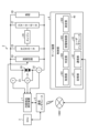
- FIG. 1 is a diagram showing a power supply system of a vehicle according to an embodiment.
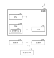
- FIG. 2 is a block diagram showing an example of the configuration of the internal resistance measuring device.
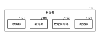
- FIG. 3 is a functional block diagram showing the configuration of functions realized in the control section.
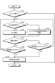
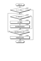
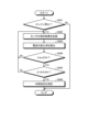
- FIG. 4 is a flowchart showing the flow of processing performed by the control unit.
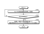
- FIG. 5 is a flowchart showing the flow of processing performed by the control unit.
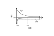
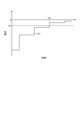
- FIG. 6 is a graph showing an example of battery voltage change.
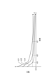
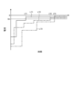
- FIG. 7 is a graph showing an example of battery voltage changes.
- FIG. 8 is a graph showing an example of battery voltage change.
- FIG. 9 is a flowchart showing the flow of processing performed by the control unit according to the second embodiment.
- FIG. 10 is a graph showing an example of the rate of change in battery voltage.
- FIG. 11 is a flowchart showing the flow of processing performed by the control unit according to the third embodiment.
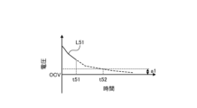
- FIG. 12 is a graph showing an example of battery voltage change.
- FIG. 13 is a flowchart showing the flow of processing performed by the control unit according to the fourth embodiment.
- FIG. 14 is a graph showing an example of changes in the current flowing from the battery.
- FIG. 15 is a graph showing an example of a change in the current flowing from the battery.
- FIG. 16 is a flowchart showing the flow of processing performed by the control unit according to a modification of the fourth embodiment.
- FIG. 17 is a graph showing an example of the rate of change in the current flowing from the battery.
- FIG. 18 is a block diagram showing the configuration of another embodiment of the internal resistance measurement system.
- FIG. 19 is a block diagram showing the configuration of another embodiment of the internal resistance measurement system.
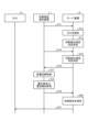
- FIG. 20 is a sequence diagram for explaining the operation of the internal resistance measurement system.
- FIG. 1 is a diagram showing a power supply system of a vehicle 2 according to an embodiment of the present invention.
- the battery 20 is a rechargeable battery containing an electrolyte, and is configured by, for example, a lead acid battery, a lithium ion battery, a nickel cadmium battery, a nickel hydride battery, or the like.
- Battery 20 is charged by alternator 25 to drive starter motor 27 and supply power to load 28 .
- the starter motor 27 is configured by, for example, a DC motor, generates rotational force using electric power supplied from the battery 20, and starts the engine 26.
- the engine 26 is configured by, for example, a reciprocating engine such as a gasoline engine and a diesel engine, or a rotary engine.
- the engine 26 is started by a starter motor 27, drives drive wheels via a transmission, provides propulsive force to the vehicle 2A, and also drives the alternator 25.
- the alternator 25 as a generator is driven by the engine 26 to generate alternating current power, converts the generated alternating current power into direct current power by a rectifier circuit, and charges the battery 20.
- the load 28 includes, for example, an electric steering motor, a defogger, a seat heater, an ignition coil, a car audio system, a car navigation system, and the like, and is operated by electric power supplied from the battery 20 .
- the vehicle 2 also includes an ECU (Electronic Control Unit) 3 that is a host device that controls the main control of the drive system of the vehicle 2, an internal resistance measuring device 1 as an internal resistance measuring system that measures the internal resistance of the battery 20, and a voltage It has a sensor 21, a current sensor 22, a temperature sensor 23, and a discharge circuit 24.
- ECU Electronic Control Unit
- the voltage sensor 21, the current sensor 22, and the temperature sensor 23 are sensors used to measure the internal resistance of the battery 20.
- Voltage sensor 21 measures the terminal voltage of battery 20 and outputs a signal indicating the measured voltage to internal resistance measuring device 1 .
- the current sensor 22 measures the charging current and discharging current of the battery 20 and outputs a signal indicating the measured current to the internal resistance measuring device 1.
- the temperature sensor 23 measures the temperature of the electrolyte of the battery 20 or the surroundings of the battery 20 and outputs a signal indicating the measured temperature to the control unit 10.
- the discharge circuit 24 is a circuit used to measure the internal resistance of the battery 20.
- the discharge circuit 24 is, for example, a circuit configured by connecting a semiconductor switch and a resistance element in series, and discharges the battery 20 by turning the semiconductor switch on and off according to control from the internal resistance measuring device 1. .
- the discharge circuit 24 can also discharge the battery 20 in a predetermined (for example, rectangular waveform) pattern.
- the predetermined pattern also includes, for example, a pattern in which discharge is performed a predetermined number of times.
- the internal resistance measuring device 1 acquires the signals output from the voltage sensor 21, the current sensor 22, and the temperature sensor 23 when the battery 20 is discharged in a predetermined pattern, and measures the internal resistance of the battery 20 based on the acquired signals. Measure internal resistance. Note that instead of having the internal resistance measuring device 1, voltage sensor 21, current sensor 22, temperature sensor 23, and discharge circuit 24 as separate configurations, a configuration that combines some or all of these can be used as an internal resistance measuring device. Good too.
- FIG. 2 is a block diagram showing an example of the configuration of the internal resistance measuring device 1.
- the internal resistance measuring device 1 includes a control unit 10 including a CPU (Central Processing Unit) 10a, a ROM (Read Only Memory) 10b, and a RAM (Random Access Memory) 10c, a storage unit 11, a communication unit 12, an interface 13, and a bus. 14.
- the control unit 10 may be configured by a DSP (Digital Signal Processor), an FPGA (Field Programmable Gate Array), an ASIC (Application Specific Integrated Circuit), or the like instead of the CPU 10a.
- DSP Digital Signal Processor
- FPGA Field Programmable Gate Array
- ASIC Application Specific Integrated Circuit
- the bus 14 is a group of signal lines that connects the CPU 10a, ROM 10b, RAM 10c, storage section 11, communication section 12, and interface 13 to each other and enables information to be exchanged between them.
- the communication unit 12 communicates with the ECU 3 and exchanges various information.
- the interface 13 converts and acquires signals supplied from the voltage sensor 21 , current sensor 22 , and temperature sensor 23 into digital signals, and outputs a control signal for controlling the discharge circuit 24 .
- the storage unit 11 is constituted by a nonvolatile memory, and stores, for example, various threshold values described below.
- the ROM 10b is made up of a non-volatile semiconductor memory and stores the program 10ba and the like.
- the RAM 10c is composed of a semiconductor memory or the like, and stores data generated when the CPU 10a executes the program 10ba, measurement results of the voltage sensor 21, current sensor 22, and temperature sensor 23, and data generated by the CPU 10a using these measurement results. Stores various calculated values.
- the CPU 10a controls each part based on a program 10ba stored in the ROM 10b.
- the functions of the control unit 10 are realized as a functional unit by the CPU 10a reading out and executing the program 10ba from the ROM 10b.
- the program 10ba stored in the ROM 10b may be rewritten by a known method such as communication with a cloud server via the ECU 3, for example.
- FIG. 3 is a functional block diagram showing the configuration of functions realized in the control unit 10 by the CPU 10a executing the program 10ba.
- the control unit 10 an acquisition unit 101, a determination unit 102, a discharge control unit 103, and a measurement unit 104 are realized.
- the acquisition unit 101 acquires the voltage value of the battery 20, the current value of the current flowing from the battery 20, and the temperature of the battery 20 indicated by the signals output from the voltage sensor 21, current sensor 22, and temperature sensor 23 and acquired by the interface 13. do.
- the determination unit 102 determines whether or not the internal resistance of the battery 20 can be measured in advance, based on the physical quantity acquired by the acquisition unit 101 when the engine 26 is stopped and the alternator 25 is stopped. For example, the determination unit 102 estimates the open circuit voltage (OCV) of the battery 20, and if the voltage of the battery 20 satisfies a predetermined condition with respect to the estimated open circuit voltage (OCV), , it is determined that the internal resistance of the battery 20 can be measured, and if the voltage of the battery 20 does not meet a predetermined condition with respect to the estimated open circuit voltage (OCV), the internal resistance of the battery 20 cannot be measured. It is determined that there is.
- OCV open circuit voltage
- the open circuit voltage (OCV) can be estimated, for example, by a method using an approximate formula disclosed in Japanese Patent No. 4785056.
- OCV open circuit voltage
- the voltage between the terminals may be estimated as the open circuit voltage (OCV).
- the open circuit voltage (OCV) may be estimated based on the voltage across the terminals of the battery 20 measured at the timing closest to when the engine 26 is started, that is, the voltage across the terminals of the battery 20 measured immediately before the engine 26 is started.
- the discharge control unit 103 controls the discharge circuit 24 so that the battery 20 is discharged in a predetermined pattern.
- the measurement unit 104 measures the internal resistance of the battery 20 using the voltage value and current value of the battery 20 acquired by the acquisition unit 101 when the discharge circuit 24 discharges the battery 20 in a predetermined pattern.
- the internal resistance of the battery 20 is, for example, the voltage and current of the battery 20 when the controller 10 controls the discharge circuit 24 to discharge the battery 20 in a predetermined pattern, and the discharge is performed in a predetermined pattern.
- the change is obtained by measuring the change using the voltage sensor 21 and the current sensor 22, and calculating the internal resistance from the measurement results. Examples of methods for calculating the internal resistance value by discharging the battery 20 in a predetermined pattern include the method disclosed in Japanese Patent No. 3960998 and the method disclosed in Japanese Patent No. 4494904. , may be calculated using other known methods.
- FIG. 4 is a flowchart showing the flow of processing executed by the control unit 10 when measuring the internal resistance of the battery 20.
- the control unit 10 executes the process shown in FIG. 4, for example, at a predetermined cycle or at a predetermined timing.
- the control unit 10 determines whether the engine 26 is stopped (step S101). To determine whether the engine 26 is stopped, the control unit 10 inquires of the ECU 3 about the state of the engine 26 via the communication unit 12, for example. When the control unit 10 receives a response indicating ignition off from the ECU 3, it determines that the engine 26 is in a stopped state (YES in step S101), and proceeds to step S102. When the control unit 10 receives a response indicating that the ignition is on from the ECU 3, the control unit 10 determines that the engine 26 is not stopped (NO in step S101), and ends the process of FIG. 4.
- the ECU 3 defines a state where the engine 26 and the electric motor are not operating as a stopped state, and when the vehicle 2 is an electric vehicle, a state where the electric motor is not operating is defined as a stopped state. You can also use it as
- the control unit 10 determines in step S102 whether the open circuit voltage (OCV) of the battery 20 has been estimated. If the open circuit voltage (OCV) of the battery 20 has been estimated (YES in step S102), the control unit 10 acquires the voltage measurement result from the voltage sensor 21 and the current measurement result from the current sensor 22. and is recorded (step S104), and the process flow moves to step S105.
- Step S104 is an example of an acquisition step.
- FIG. 5 is a flowchart showing the flow of processing in which the control unit 10 estimates the open circuit voltage (OCV).
- the control unit 10 acquires and records the measurement results of the voltage sensor 21 and the current sensor 22 (step S201).
- the control unit 10 determines whether a predetermined time has elapsed since starting the process of estimating the open circuit voltage (OCV) (step S202). If the predetermined time has not elapsed (NO in step S202), the control unit 10 returns the predetermined flow to step S201.
- step S202 the control unit 10 uses the voltage recorded in step S201 and the measurement time, which is the elapsed time after starting the process in FIG. 5, to determine the predetermined time.
- the fitting calculation is performed using the voltage characteristic formula, and the open circuit voltage (OCV) is calculated.
- OCV open circuit voltage
- step S203 can be calculated by, for example, the method disclosed in Japanese Patent No. 4785056.
- step S105 the control unit 10 determines whether the polarization state of the battery 20 is charging polarization. For example, if the measured voltage measured by the voltage sensor 21 is higher than the estimated open circuit voltage (OCV), the control unit 10 determines that charging polarization is occurring (YES in step S105), and the voltage measured by the voltage sensor 21 is determined to be charging polarization. If the measured voltage is lower than the estimated open circuit voltage (OCV), it is determined that there is discharge polarization (NO in step S105).
- OCV estimated open circuit voltage
- Step S106 the control unit 10 determines that the battery 20 is in a charging polarization state, the measured voltage measured by the voltage sensor 21 is less than or equal to the sum of the estimated open circuit voltage (OCV) and a predetermined threshold value a1.
- Step S106 If the measured voltage ⁇ open circuit voltage (OCV)+threshold a1 is not satisfied (NO in step S106), the control unit 10 returns the flow of the process to step S102. If the measured voltage ⁇ open circuit voltage (OCV)+threshold a1 (YES in step S106), the control unit 10 moves the process to step S108. The process of step S108 will be described later.
- step S107 the control unit 10 determines that the battery 20 is not in a state of charge polarization, that is, when it is determined that the battery 20 is in a state of discharge polarization. It is determined whether the difference between (OCV) and a predetermined threshold a2 is greater than or equal to (step S107). If the measured voltage ⁇ open circuit voltage (OCV) ⁇ threshold a2 is not satisfied (NO in step S107), the control unit 10 returns the flow of processing to step S102. If the measured voltage ⁇ open circuit voltage (OCV) ⁇ threshold a2 (YES in step S107), the control unit 10 moves the process to step S108.
- the processing from step S103 to step S107 is an example of a determination step.
- step S108 the control unit 10 controls the discharge circuit 24 so that the battery 20 is discharged in a predetermined pattern, and measures the internal resistance of the battery 20.
- the control unit 10 uses the voltage value and current value of the battery 20 acquired by the acquisition unit 101 when the discharge circuit 24 discharges the battery 20 in a predetermined pattern to determine the internal resistance value of the battery 20. Calculate.
- the step of controlling the discharge circuit 24 in step S108 is an example of a discharge control step, and the step of calculating the internal resistance value is an example of a measurement step of measuring the internal resistance of the battery 20.
- control unit 10 may detect the state of the battery 20 based on the calculated internal resistance value. Further, the control unit 10 may notify the ECU 3 of the detection results of the internal resistance and state of the battery 20.
- the ECU 3 that has acquired the detection results of the internal resistance and condition of the battery 20 may, for example, notify the condition of the battery 20 on the instrument panel based on the acquired results.
- the notification of the state of the battery 20 is not limited to notification on the instrument panel, and may be an alarm sound or voice, for example. Further, these notifications may be made at the timing when the accessory power source is turned on in the vehicle 2 or at the timing when the ignition is turned on.
- FIG. 6 is a graph showing an example of changes in the voltage of the battery 20.
- a line L11 in the graph shown in FIG. 6 is an example of a voltage change after the vehicle 2 is stopped, the drive of the load 28 is stopped, and the engine 26 is stopped, and when the battery 20 is in a charged polarized state. shows the change in voltage.
- a line L12 in the graph shown in FIG. 6 is an example of a voltage change when the room lamp and headlights are turned on for a while after the engine 26 is stopped, and then the loop lamp and headlights are turned off, and the battery 20 is in a state of discharge polarization. It shows the change in voltage when .
- the control unit 10 controls the battery 20 after time t11 when the voltage of the battery 20 becomes equal to or lower than the open circuit voltage (OCV) + threshold value a1 at line L11. Measure the internal resistance of the Further, when the battery 20 is in the discharge polarization state, the control unit 10 measures the internal resistance after time t12 when the voltage of the battery 20 becomes equal to or higher than the open circuit voltage (OCV) - threshold value a2 at line L12.
- the control unit 10 determines whether the battery 20 is polarized when the voltage of the battery 20 is within a predetermined range from the open circuit voltage (OCV). Since the internal resistance is measured after the voltage fluctuation due to the voltage decreases, the internal resistance can be measured with high accuracy. Furthermore, even if the voltage of the battery 20 varies depending on the usage status of the vehicle 2 as shown by the line L11 and the line L12, the control unit 10 can control the voltage of the battery 20 from the open circuit voltage (OCV) to a predetermined value. Since the internal resistance is measured after the voltage is within the range and the fluctuation in voltage due to polarization becomes small, the internal resistance can be measured with high accuracy.
- OCV open circuit voltage
- FIG. 7 is a diagram showing an example of a change in the voltage of the battery 20 after the engine 26 has stopped.
- Line L21, line L22, and line L23 of the graph shown in FIG. 7 show changes in voltage when the battery 20 is in a charging polarization state
- line L22 shows the charging voltage from the battery 20 due to the voltage change of line L23.
- the line L21 shows the voltage change in the battery 20 whose charging voltage is higher than the voltage change in the line L22.
- the internal resistance is measured after time t21 when the voltage of the battery 20 becomes equal to or lower than the open circuit voltage (OCV) + threshold value a1 at line L21
- the internal resistance is measured after time t22 when the voltage of the battery 20 becomes equal to or lower than the open circuit voltage (OCV)+threshold value a1 on the line L22.
- the internal resistance is measured after time t23 when the voltage of the battery 20 becomes equal to or lower than the open circuit voltage (OCV) + threshold value a1 at line L23. conduct.
- FIG. 8 is a diagram showing an example of a change in the voltage of the battery 20 due to a difference in temperature.
- Line L31 and line L32 of the graph shown in FIG. 8 show the change in voltage when the battery 20 is in a state of charge polarization
- line L31 shows the change in voltage when the battery 20 is at a high temperature
- line L32 shows the change in voltage when the battery 20 is in a high temperature state.
- the internal resistance is measured after time t32 when the voltage of the battery 20 becomes equal to or lower than the open circuit voltage (OCV)+threshold value a1 at line L32.
- the control unit 10 can control the voltage of the battery 20 to be within a predetermined range from the open circuit voltage (OCV) to reduce the voltage due to polarization. Since the internal resistance is measured after the fluctuation becomes small, the internal resistance can be measured with high accuracy.
- OCV open circuit voltage
- the determination unit 102 determines whether the battery It is determined that the internal resistance of 20 is measurable.
- FIG. 9 is a flowchart showing the flow of processing executed by the control unit 10 according to the second embodiment when measuring the internal resistance of the battery 20.
- the control unit 10 executes the process shown in FIG. 9, for example, at a predetermined cycle or at a predetermined timing.
- step S301 determines whether the engine 26 is stopped, as in step S101 (step S301). If the control unit 10 determines in step S301 that the engine 26 is not in a stopped state (NO in step S301), it ends the process of FIG. 9 . If the control unit 10 determines in step S301 that the engine 26 is stopped (YES in step S301), the process proceeds to step S302.
- the control unit 10 acquires and records the measurement results of the voltage sensor 21 and the current sensor 22 in step S302. Next, the control unit 10 calculates the rate of change of the recorded voltage (step S303).
- the control unit 10 sets the latest voltage measurement result as V n , the measurement result immediately before the latest voltage measurement result as V n-1 , and measures V n-1 and then sets V n .
- the rate of change is set as dv/dt.
- step S304 determines whether dv/dt ⁇ 0 (step S304). If dv/dt ⁇ 0 (YES in step S304), the control unit 10 determines whether dv/dt is greater than or equal to a predetermined threshold b2 (step S305). If dv/dt is not equal to or greater than the threshold value b2 (NO in step S305), the control unit 10 returns the flow of processing to step S302. If dv/dt is equal to or greater than the threshold value b2 (YES in step S305), the control unit 10 measures the internal resistance of the battery 20 in step S307 in the same manner as in step S108.
- step S304 the control unit 10 determines whether dv/dt is less than or equal to a predetermined threshold b1 (step S306). If dv/dt is not equal to or less than the threshold value b1 (NO in step S306), the control unit 10 returns the flow of processing to step S302. If dv/dt is less than or equal to the threshold value b1 (YES in step S306), the control unit 10 measures the internal resistance of the battery 20 in step S307 as in step S108.
- FIG. 10 is a diagram showing an example of the rate of change in the voltage of the battery 20.
- a line L41 in the graph shown in FIG. 10 indicates the rate of change in voltage when the battery 20 is in a charge polarization state, and a line L42 in the graph shown in FIG. shows the rate of change.
- the control unit 10 measures the internal resistance after time t41 when the rate of change in the voltage of the battery 20 becomes equal to or less than the threshold value b2 on the line L41. . Further, when the battery 20 is in a state of discharge polarization, the control unit 10 measures the internal resistance after time t42 when the rate of change in the voltage of the battery 20 becomes equal to or higher than the threshold value b1 on the line L42.
- the control unit 10 controls the internal operation after the polarization is eliminated and the rate of change in voltage of the battery 20 becomes small. Since the resistance is measured, the internal resistance can be measured with high accuracy.
- the determination unit 102 estimates the time when the voltage value of the battery 20 falls within a predetermined range from the open circuit voltage (OCV) based on the voltage value acquired by the acquisition unit 101, and estimates the time when the voltage value of the battery 20 falls within a predetermined range from the open circuit voltage (OCV). If the time has passed, it is determined that the internal resistance of the battery 20 can be measured.
- OCV open circuit voltage
- FIG. 11 is a flowchart showing the flow of processing executed by the control unit 10 according to the third embodiment when measuring the internal resistance of the battery 20.
- the control unit 10 executes the process shown in FIG. 11, for example, at a predetermined cycle or at a predetermined timing.
- step S401 determines whether the engine 26 is stopped, as in step S101 (step S401). If the control unit 10 determines in step S401 that the engine 26 is not in a stopped state (NO in step S401), it ends the process of FIG. 11. If the control unit 10 determines in step S401 that the engine 26 is stopped (YES in step S401), the process proceeds to step S402.
- the control unit 10 determines whether the open circuit voltage (OCV) of the battery 20 has been estimated in step S402. If the open circuit voltage (OCV) of the battery 20 has been estimated (YES in step S402), the control unit 10 moves the process to step S405.
- the control unit 10 sets a measurement start time for measuring the internal resistance (step S404).
- the control unit 10 determines that the voltage of the battery 20 is the open circuit voltage based on the time change of the voltage recorded when estimating the open circuit voltage (OCV). (OCV)+Threshold value a1 or less is estimated, and the estimated time is set as the measurement start time.
- the control unit 10 determines whether the voltage of the battery 20 is the open circuit voltage (OCV) based on the time change of the voltage recorded when estimating the open circuit voltage (OCV). ) - Estimate the time when the threshold value a2 or higher is reached, and set the estimated time as the measurement start time.
- OCV open circuit voltage
- control unit 10 determines whether the current time is after the measurement start time set in step S404 (step S405). If the current time is before the measurement start time (NO in step S405), the control unit 10 returns the flow of processing to step S402. Note that if the control unit 10 determines NO in step S405, it may repeat the process of step S405 until the time is after the measurement start time.
- control unit 10 measures the internal resistance of the battery 20 in step S406 as in step S108.
- FIG. 12 is a diagram showing an example of changes in the voltage of the battery 20.
- a line L51 in the graph shown in FIG. 12 indicates a change in voltage when the battery 20 is in a charging polarization state.
- the control unit 10 starts measuring at time t52 when the change in the voltage of the battery 20 becomes equal to or less than the open circuit voltage (OCV) + threshold value a1 at the line L51. Time.
- the control unit 10 does not measure the internal resistance at time t51, which is before time t52, but measures the internal resistance after time t52.
- control unit 10 measures the internal resistance after the voltage of the battery 20 falls within a predetermined range from the open circuit voltage (OCV) and voltage fluctuations due to polarization become small. can be measured with high precision.
- OCV open circuit voltage
- the determination unit 102 determines that the current value inside the battery 20 is Determine that resistance can be measured.
- FIG. 13 is a flowchart showing the flow of processing executed by the control unit 10 of the fourth embodiment when measuring the internal resistance of the battery 20.
- the control unit 10 executes the process shown in FIG. 13, for example, at a predetermined cycle or at a predetermined timing.
- step S501 determines whether the engine 26 is stopped, as in step S101 (step S501). If the control unit 10 determines in step S501 that the engine 26 is not in a stopped state (NO in step S501), it ends the process of FIG. 13. When the control unit 10 determines in step S501 that the engine 26 is in a stopped state (YES in step S501), the process proceeds to step S502.
- step S502 the control unit 10 acquires and records the measurement results of the voltage sensor 21 and the current sensor 22 (step S502).
- the control unit 10 determines whether the latest current value Inew recorded in step S502 is greater than or equal to a predetermined threshold value Ith (step S503). If the current value Inew ⁇ threshold value Ith is not satisfied (NO in step S503), the control unit 10 returns the flow of processing to step S502.
- the control unit 10 measures the internal resistance of the battery 20 in step S504 as in step S108.
- FIG. 14 is a diagram showing an example of a change in the current flowing from the battery 20 after the engine 26 is stopped. Note that in the graph shown in FIG. 14, the current value when the battery 20 is discharging is negative. According to the above processing, when the current changes as shown in FIG. 14, if the current value of the current flowing from the battery 20 is less than the threshold value Ith, the internal resistance is not measured and the current flowing from the battery 20 is changed. The internal resistance is measured after time t61 when the value becomes equal to or greater than the threshold value Ith.
- control unit 10 measures the internal resistance after the current flowing from the battery 20 is small and the fluctuations in the current are small, so that the internal resistance can be measured with high accuracy.
- FIG. 15 is a diagram showing an example of a change in the current flowing from the battery 20 after the engine 26 is stopped.
- Line L71, line L72, and line L73 in the graph shown in FIG. 15 indicate changes in the current flowing from battery 20 in different vehicle types.
- the internal resistance is measured after time t21 when the current value becomes equal to or less than the threshold value Ith on the line L71, and the current flowing from the battery 20 is measured.
- the internal resistance is measured after time t72 when the current value becomes equal to or less than the threshold value Ith at line L72.
- the internal resistance is calculated after time t73 when the current value becomes equal to or less than the threshold value Ith on the line L73.
- the control unit 10 adjusts the internal resistance after the current value of the current flowing from the battery 20 becomes equal to or less than the threshold value Ith and the fluctuation of the current becomes small.
- the internal resistance can be measured with high accuracy.
- FIG. 16 is a flowchart showing the flow of processing executed by the control unit 10 according to a modification of the fourth embodiment when measuring the internal resistance of the battery 20.
- the control unit 10 executes the process shown in FIG. 16, for example, at a predetermined cycle or at a predetermined timing.
- step S101 determines whether the engine 26 is stopped, as in step S101 (step S601). If the control unit 10 determines in step S601 that the engine 26 is not in a stopped state (NO in step S601), it ends the process of FIG. 16. If the control unit 10 determines in step S601 that the engine 26 is in a stopped state (YES in step S601), the process proceeds to step S602.
- the control unit 10 acquires and records the measurement results of the voltage sensor 21 and the current sensor 22 in step S602. Next, the control unit 10 calculates the rate of change of the recorded current value (step S603).
- the control unit 10 determines whether the latest current value Inew recorded in step S602 is greater than or equal to the threshold value Ith (step S604). If the current value Inew ⁇ threshold value Ith is not satisfied (NO in step S604), the control unit 10 returns the flow of processing to step S602.
- the control unit 10 determines whether di/dt is less than or equal to a predetermined threshold value dith (step S605). If di/dt is not equal to or less than the threshold value ith (NO in step S605), the control unit 10 returns the flow of processing to step S602. If di/dt is less than or equal to the threshold value ith (YES in step S605), the control unit 10 measures the internal resistance of the battery 20 in step S606 in the same manner as in step S108.
- FIG. 17 is a diagram showing an example of the rate of change of the current flowing from the battery 20.
- the control unit 10 does not measure the internal resistance at time t81 or time t82 when the rate of change in the current flowing from the battery 20 exceeds the threshold dith, and instead measures the change in the current flowing from the battery 20.
- the internal resistance is measured after time t83 when the ratio becomes equal to or less than the threshold dith.
- control unit 10 measures the internal resistance after the fluctuation in the current flowing from the battery 20 becomes small, so that the internal resistance can be measured with high accuracy.
- FIG. 18 is a block diagram showing the configuration of another embodiment of the internal resistance measurement system.
- the ECU 3 as an example of an internal resistance measuring device includes a control section 30, a storage section 31, an interface 33, and a bus (not shown).
- the CPU, ROM, RAM, storage section 31, and interface 33 are interconnected by a bus, and information is exchanged between them.
- the storage unit 31 is constituted by a nonvolatile memory, and stores the various threshold values described above.
- control unit 30 The functions of the control unit 30 are realized as a functional unit by the CPU reading a program from the ROM and executing it.
- the CPU executes a program stored in the ROM, an acquisition section 301, a determination section 302, a discharge control section 303, and a measurement section 304 are realized in the control section 30.
- the acquisition unit 301 acquires the voltage value of the battery 20, the current value of the current flowing from the battery 20, and the temperature of the battery 20 indicated by the signals output from the voltage sensor 21, current sensor 22, and temperature sensor 23 and acquired by the interface 33. do.
- the determination unit 302 determines whether the internal resistance of the battery 20 can be measured based on the physical quantity acquired by the acquisition unit 301 when the engine 26 is stopped and the alternator 25 is stopped.
- the discharge control unit 303 controls the discharge circuit 24 so that the battery 20 is discharged in a predetermined pattern.
- the measurement unit 304 measures the internal resistance of the battery 20 using the voltage value and current value of the battery 20 acquired by the acquisition unit 301 while the discharge circuit 24 is discharging the battery 20 in a predetermined pattern. Measure in the same manner as 104.
- the internal resistance of the battery 20 is measured after the fluctuation in voltage due to polarization becomes small by the control unit 30 executing any of the processes of the first to fourth embodiments. Resistance can be measured with high precision.
- the internal resistance of the battery 20 may be measured by a server device connected to a communication network.
- FIG. 19 is a block diagram showing the configuration of another embodiment of the internal resistance measurement system.
- the communication interface 5 is an interface that performs wireless communication via the communication network 1000, and is connected to the internal resistance measuring device 1.
- Internal resistance measuring device 1 connects to communication network 1000 via communication interface 5 and exchanges information with server device 4 .
- the server device 4 includes a control section 40, a storage section 41, a communication section 42, a user interface 43, and a bus (not shown).
- the control unit 40 like the control unit 10, includes a CPU, ROM, and RAM.
- the CPU, ROM, RAM, storage section 41, communication section 42, and user interface 43 are interconnected by a bus and exchange information between them.
- the communication unit 42 communicates with the internal resistance measuring device 1 via the communication network 1000, and exchanges information with the internal resistance measuring device 1.
- the storage unit 41 has a storage medium such as a hard disk device, and stores the various threshold values described above.
- the user interface 43 includes a mouse and a keyboard for inputting information, and a display device for displaying information. Note that the server device 4 may have a configuration that does not include the user interface 43.
- control unit 40 The functions of the control unit 40 are realized as a functional unit by the CPU reading a program from the ROM and executing it.
- the CPU executes a program stored in the ROM, in the control unit 40, an acquisition unit 401, a determination unit 402, a discharge control unit 403, and a measurement unit 404 are realized.
- the acquisition unit 401 acquires the voltage value, current value, and temperature acquired by the acquisition unit 101 and transmitted from the internal resistance measuring device 1 via the communication unit 42.
- the determination unit 402 determines whether the internal resistance of the battery 20 can be measured based on the physical quantity acquired by the acquisition unit 101 when the engine 26 is stopped and the alternator 25 is stopped.
- the discharge control unit 403 transmits a discharge instruction to the internal resistance measuring device 1 instructing the battery 20 to be discharged in a predetermined pattern. do.
- the measurement unit 404 measures the voltage of the battery 20 acquired by the acquisition unit 101 when the control unit 10 controls the discharge circuit 24 in response to a discharge instruction and the discharge circuit 24 discharges the battery 20 in a predetermined pattern. value and current value are acquired from the internal resistance measuring device 1, and the internal resistance of the battery 20 is measured in the same manner as the measuring unit 104 using the acquired voltage value and current value.
- FIG. 20 is a sequence diagram for explaining the operation of the internal resistance measurement system configured as shown in FIG. 19.
- the internal resistance measuring device 1 transmits the voltage value and current value acquired by the acquisition unit 101 at a predetermined period to the server device 4 via the communication interface 5 (step S11 ).
- the server device 4 acquires the voltage value and current value transmitted from the internal resistance measuring device 1. If the open circuit voltage (OCV) has not been estimated yet, the server device 4 estimates the open circuit voltage (OCV) similarly to the internal resistance measuring device 1 according to the first embodiment (step S12). Next, the server device 4 determines whether or not internal resistance can be measured by the same process as steps S105 to S107 (step S13). If the server device 4 determines that it is impossible to measure the internal resistance, it then acquires the voltage value and current value transmitted from the internal resistance measuring device 1 (step S14), and uses the acquired voltage value and the estimated open voltage value. Based on the circuit voltage (OCV), it is determined whether the internal resistance can be measured (step S15).
- the server device 4 determines that the internal resistance can be measured, it transmits a discharge instruction to the internal resistance measuring device 1 (step S16).
- the internal resistance measuring device 1 controls the discharge circuit 24 so that the battery 20 is discharged in a predetermined pattern in response to the discharge instruction (step S17). Further, the internal resistance measuring device 1 acquires the voltage value and current value of the battery 20 acquired by the acquisition unit 101 while the discharge circuit 24 is discharging the battery 20 in a predetermined pattern (step S18), The acquired voltage value and current value are transmitted to the server device 4 (step S19).
- the server device 4 acquires the voltage value and current value transmitted from the server device 4, and measures the internal resistance of the battery 20 similarly to the measurement unit 104 based on the acquired voltage value and current value (step S20 ).
- the server device 4 transmits the internal resistance measurement result to the ECU 3 (step S21).
- the internal resistance is measured after the voltage of the battery 20 falls within a predetermined range from the open circuit voltage (OCV) and voltage fluctuations due to polarization become small, so it is not possible to accurately measure the internal resistance.
- OCV open circuit voltage
- the processing performed by the server device 4 may be executed by a terminal device such as a personal computer connected to the communication network 1000. Further, the server device 4 may determine whether or not internal resistance can be measured using the method of the second embodiment, the third embodiment, or the fourth embodiment.
- the vehicle 2 may be, for example, a hybrid vehicle equipped with an electric motor that assists the engine 26 or an electric vehicle driven by an electric motor. It may also be an electric vehicle such as.
- the battery 20 starts a high voltage system (a system for driving an electric motor) made up of a lithium battery or the like, and the high voltage system starts the engine 26 or the electric motor.
- the vehicle 2 has the internal resistance measuring device 1 and the discharge circuit 24, but the internal resistance measuring device 1 and the discharge circuit 24 are provided in the vehicle 2.
- the internal resistance measuring device 1 and the discharge circuit 24 are provided in the vehicle 2.
- the device 1 and the discharge circuit 24 may be included.
- devices having the internal resistance measuring device 1 and the discharge circuit 24 are not limited to mobile objects, and devices using the battery 20 in gas, water, railway, communication, power equipment, etc. It may also include a circuit 24.
- At least two of the methods of the first to fourth embodiments may be combined to determine whether internal resistance can be measured.
- the present invention can be used in an internal resistance measuring system, an internal resistance measuring device, and an internal resistance measuring method.
Landscapes
- Engineering & Computer Science (AREA)
- Manufacturing & Machinery (AREA)
- Chemical & Material Sciences (AREA)
- Chemical Kinetics & Catalysis (AREA)
- Electrochemistry (AREA)
- General Chemical & Material Sciences (AREA)
- Power Engineering (AREA)
- Physics & Mathematics (AREA)
- General Physics & Mathematics (AREA)
- Tests Of Electric Status Of Batteries (AREA)
- Secondary Cells (AREA)
Abstract
分極の影響が少ない適切なタイミングでバッテリの内部抵抗の測定を行う。充電可能なバッテリの内部抵抗を測定する内部抵抗測定システムであって、前記バッテリから流れる電流の電流値と前記バッテリの電圧値を取得する取得部と、前記バッテリの充電が停止しているときに前記取得部が取得した電圧値及び電流値の少なくとも一方に基づいて前記バッテリの内部抵抗の測定の可否を判定する判定部と、前記判定部により測定可能と判定された場合、前記バッテリからの放電が所定のパターンで行われるように前記バッテリを放電させる放電制御部と、前記バッテリからの放電が所定のパターンで行われているときに前記取得部が取得した電流値と電圧値に基づいて、前記バッテリの内部抵抗を測定する測定部と、を備える。
Description
本発明は、内部抵抗測定システム、内部抵抗測定装置及び内部抵抗測定方法に関する。
充放電可能なバッテリの状態を監視する発明として、例えば特許文献1に開示された監視装置がある。この監視装置は、ある大きさ以上のバッテリ放電が生じたと判断された場合、前回のバッテリ内部抵抗を算出した時点から、ある大きさ以上のバッテリ液温度の変動があった場合、前回のバッテリ内部抵抗を算出した時点から、ある大きさ以上のバッテリ電圧値の変動があった場合、又は前回のバッテリ内部抵抗を算出した時点から、ある大きさ以上のバッテリ充放又は放電があった場合、バッテリの内部抵抗を算出する。
充放電可能なバッテリを搭載した車両においては、車両の使用状態によってバッテリの状態も変化する。例えばエンジンが停止する直前に充電している場合と、エンジンが停止する直前に放電している場合とでバッテリの分極の状態が異なる。特許文献1に開示された監視装置では、分極の状態を考慮していないため、バッテリに分極が発生していると分極の変動によって内部抵抗の測定結果に影響がでるおそれがある。
本発明は、上記に鑑みてなされたものであって、分極の影響が少ない適切なタイミングでバッテリの内部抵抗の測定を行う技術を提供することを目的とする。
上述した課題を解決し、目的を達成するために、本発明の一態様に係る内部抵抗測定システムは、充電可能なバッテリの内部抵抗を測定する内部抵抗測定システムであって、前記バッテリから流れる電流の電流値と前記バッテリの電圧値を取得する取得部と、前記バッテリの充電が停止しているときに前記取得部が取得した電圧値及び電流値の少なくとも一方に基づいて前記バッテリの内部抵抗の測定の可否を判定する判定部と、前記判定部により測定可能と判定された場合、前記バッテリからの放電が所定のパターンで行われるように前記バッテリを放電させる放電制御部と、前記バッテリからの放電が所定のパターンで行われているときに前記取得部が取得した電流値と電圧値に基づいて、前記バッテリの内部抵抗を測定する測定部と、を備える。
本発明の一態様に係る内部抵抗測定システムにおいては、前記判定部は、前記取得部が取得した電圧値から前記バッテリの開回路電圧を推定し、前記取得部が取得した電圧値が前記開回路電圧から所定範囲内にある場合、前記バッテリの内部抵抗の測定を可能と判定する構成でもよい。
本発明の一態様に係る内部抵抗測定システムにおいては、前記判定部は、前記取得部が取得した電圧値の変化率が予め定められた条件を満たしている場合、前記バッテリの内部抵抗の測定を可能と判定する構成でもよい。
本発明の一態様に係る内部抵抗測定システムにおいては、前記判定部は、前記取得部が取得した電圧値から前記バッテリの開回路電圧を推定し、前記バッテリの電圧値が前記開回路電圧から所定範囲内となる時刻を前記取得部が取得した電圧値の変化から推定し、推定した時刻を越えた場合、前記バッテリの内部抵抗の測定を可能と判定する構成でもよい。
本発明の一態様に係る内部抵抗測定システムにおいては、前記判定部は、前記取得部が取得した電流値が予め定められた条件を満たしている場合、前記バッテリの内部抵抗の測定を可能と判定する構成でもよい。
本発明の一態様に係る内部抵抗測定システムにおいては、前記判定部は、前記取得部が取得した電流値の変化率が予め定められた条件を満たしている場合、前記バッテリの内部抵抗の測定を可能と判定する構成でもよい。
本発明に係る内部抵抗測定装置は、充電可能なバッテリの内部抵抗を測定する内部抵抗測定装置であって、前記バッテリから流れる電流の電流値と前記バッテリの電圧値を取得する取得部と、前記バッテリの充電が停止しているときに前記取得部が取得した電圧値及び電流値の少なくとも一方に基づいて前記バッテリの内部抵抗の測定の可否を判定する判定部と、前記判定部により測定可能と判定された場合、前記バッテリからの放電が所定のパターンで行われるように前記バッテリを放電させる放電制御部と、前記バッテリからの放電が所定のパターンで行われているときに前記取得部が取得した電流値と電圧値に基づいて、前記バッテリの内部抵抗を測定する測定部と、を備える。
本発明の一態様に係る内部抵抗測定方法は、充電可能なバッテリの内部抵抗を測定する内部抵抗測定方法であって、前記バッテリから流れる電流の電流値と前記バッテリの電圧値を取得する取得ステップと、前記バッテリの充電が停止しているときに前記取得ステップで取得した少なくとも電圧値及び電流値の少なくとも一方に基づいて前記バッテリの内部抵抗の測定の可否を判定する判定ステップと、前記判定ステップにより測定可能と判定された場合、前記バッテリからの放電が所定のパターンで行われるように前記バッテリを放電させる放電制御ステップと、前記バッテリからの放電が所定のパターンで行われているときに前記取得ステップで取得した電流値と電圧値に基づいて、前記バッテリの内部抵抗を測定する測定ステップと、を備える。
本発明によれば、分極の影響が少ない適切なタイミングでバッテリの内部抵抗の測定を行うことができる。
以下に、本発明の実施形態を図面に基づいて詳細に説明する。なお、以下に説明する実施形態により本発明が限定されるものではない。また、図面の記載において、同一または対応する要素については適宜同一の符号を付している。
[第1実施形態]
(第1実施形態の構成)
図1は、本発明の実施形態に係る車両2の電源系統を示す図である。バッテリ20は、電解液を有する充電可能な電池であり、例えば、鉛蓄電池、リチウムイオン電池、ニッケルカドミウム電池、又はニッケル水素電池等によって構成されている。バッテリ20は、オルタネータ25によって充電され、スタータモータ27を駆動するとともに、負荷28に電力を供給する。スタータモータ27は、例えば、直流電動機によって構成され、バッテリ20から供給される電力によって回転力を発生し、エンジン26を始動する。エンジン26は、例えば、ガソリンエンジン、及びディーゼルエンジン等のレシプロエンジン、又はロータリーエンジン等によって構成されている。エンジン26は、スタータモータ27によって始動され、トランスミッションを介して駆動輪を駆動し、車両2Aに推進力を与えるとともに、オルタネータ25を駆動する。発電機としてのオルタネータ25は、エンジン26によって駆動されて交流電力を発生し、発生した交流電力を整流回路によって直流電力に変換してバッテリ20を充電する。負荷28は、例えば、電動ステアリングモータ、デフォッガ、シートヒータ、イグニッションコイル、カーオーディオ、及びカーナビゲーション等によって構成され、バッテリ20から供給される電力によって動作する。
(第1実施形態の構成)
図1は、本発明の実施形態に係る車両2の電源系統を示す図である。バッテリ20は、電解液を有する充電可能な電池であり、例えば、鉛蓄電池、リチウムイオン電池、ニッケルカドミウム電池、又はニッケル水素電池等によって構成されている。バッテリ20は、オルタネータ25によって充電され、スタータモータ27を駆動するとともに、負荷28に電力を供給する。スタータモータ27は、例えば、直流電動機によって構成され、バッテリ20から供給される電力によって回転力を発生し、エンジン26を始動する。エンジン26は、例えば、ガソリンエンジン、及びディーゼルエンジン等のレシプロエンジン、又はロータリーエンジン等によって構成されている。エンジン26は、スタータモータ27によって始動され、トランスミッションを介して駆動輪を駆動し、車両2Aに推進力を与えるとともに、オルタネータ25を駆動する。発電機としてのオルタネータ25は、エンジン26によって駆動されて交流電力を発生し、発生した交流電力を整流回路によって直流電力に変換してバッテリ20を充電する。負荷28は、例えば、電動ステアリングモータ、デフォッガ、シートヒータ、イグニッションコイル、カーオーディオ、及びカーナビゲーション等によって構成され、バッテリ20から供給される電力によって動作する。
また、車両2は、車両2の駆動系の主要な制御を司る上位装置であるECU(Electronic Control Unit)3、バッテリ20の内部抵抗を測定する内部抵抗測定システムとしての内部抵抗測定装置1、電圧センサ21、電流センサ22、温度センサ23、及び放電回路24を有している。
電圧センサ21、電流センサ22、及び温度センサ23は、バッテリ20の内部抵抗を測定するために用いられるセンサである。電圧センサ21は、バッテリ20の端子電圧を測定し、測定した電圧を示す信号を内部抵抗測定装置1へ出力する。電流センサ22は、バッテリ20の充電電流及び放電電流を測定し、測定した電流を示す信号を内部抵抗測定装置1へ出力する。温度センサ23は、バッテリ20の電解液又はバッテリ20の周囲の温度を測定し、測定した温度を示す信号を制御部10へ出力する。
放電回路24は、バッテリ20の内部抵抗を測定するために用いられる回路である。放電回路24は、例えば、半導体スイッチと抵抗素子とが直列接続されて構成された回路であり、内部抵抗測定装置1からの制御に応じて半導体スイッチをオン/オフすることでバッテリ20を放電させる。なお、放電回路24は、バッテリ20を所定の(例えば矩形波状の)パターンで放電させることもできる。所定のパターンは、例えば放電を所定回数行うパターンも含む。
内部抵抗測定装置1は、バッテリ20からの放電を所定のパターンで行ったときに電圧センサ21、電流センサ22、温度センサ23から出力される信号を取得し、取得した信号に基づいてバッテリ20の内部抵抗を測定する。なお、内部抵抗測定装置1、電圧センサ21、電流センサ22、温度センサ23、及び放電回路24を別々の構成とするのではなく、これらの一部または全てをまとめた構成を内部抵抗測定装置としてもよい。
図2は、内部抵抗測定装置1の構成の一例を示すブロック図である。内部抵抗測定装置1は、CPU(Central Processing Unit)10a、ROM(Read Only Memory)10b、及びRAM(Random Access Memory)10cを含む制御部10、記憶部11、通信部12、インターフェース13、及びバス14、を有している。なお、制御部10は、CPU10aの代わりに、DSP(Digital Signal Processor)、FPGA(Field Programmable Gate Array)、または、ASIC(Application Specific Integrated Circuit)等によって構成するようにしてもよい。
バス14は、CPU10a、ROM10b、RAM10c、記憶部11、通信部12、及びインターフェース13を相互に接続し、これらの間で情報の授受を可能とするための信号線群である。通信部12は、ECU3との間で通信を行い、各種情報の授受を行なう。インターフェース13は、電圧センサ21、電流センサ22、及び温度センサ23から供給される信号をデジタル信号に変換して取得するとともに、放電回路24を制御する制御信号を出力する。記憶部11は、不揮発性メモリによって構成され、例えば、後述する各種閾値を記憶する。
ROM10bは、不揮発性の半導体メモリ等によって構成され、プログラム10ba等を格納している。RAM10cは、半導体メモリ等によって構成され、CPU10aがプログラム10baを実行する際に生成されるデータや、電圧センサ21、電流センサ22、及び温度センサ23の測定結果、これらの測定結果を用いてCPU10aにより算出される各種の値を記憶する。
CPU10aは、ROM10bに格納されているプログラム10baに基づいて各部を制御する。制御部10の機能は、CPU10aがROM10bからプログラム10baを読み出して実行することで、機能部として実現される。なお、ROM10bに格納されているプログラム10baは、例えば、ECU3を経由したクラウドサーバとの通信等の公知の手法により書換可能になっていてもよい。
図3は、CPU10aがプログラム10baを実行することにより制御部10において実現する機能の構成を示す機能ブロック図である。制御部10においては、取得部101、判定部102、放電制御部103、及び測定部104が実現する。
取得部101は、電圧センサ21、電流センサ22、及び温度センサ23から出力されてインターフェース13が取得した信号が示すバッテリ20の電圧値、バッテリ20から流れる電流の電流値、バッテリ20の温度を取得する。
判定部102は、エンジン26が停止してオルタネータ25が停止しているときに取得部101が取得した物理量に基づいて、バッテリ20の内部抵抗の測定の可否を測定の事前に判定する。判定部102は、例えば、バッテリ20の開回路電圧(OCV:Open Circuit Voltage)を推定し、推定した開回路電圧(OCV)に対してバッテリ20の電圧が所定の条件を満たしている場合には、バッテリ20の内部抵抗を測定可能と判定し、推定した開回路電圧(OCV)に対してバッテリ20の電圧が所定の条件を満たしていない場合には、バッテリ20の内部抵抗の測定が不可であると判定する。
なお、開回路電圧(OCV)については、例えば特許第4785056号公報に開示されている近似式を用いる方法で推定することができる。また、開回路電圧(OCV)については、エンジン26の起動時に電圧センサ21が測定したバッテリ20の端子間電圧、又は電圧センサ21で周期的に測定してRAM10cに記憶されたバッテリ20の最新の端子間電圧を開回路電圧(OCV)と推定してもよい。また、エンジン26の起動時に最も近いタイミングで測定された端子間電圧、すなわちエンジン26の起動直前に測定されたバッテリ20の端子間電圧に基づいて開回路電圧(OCV)を推定してもよい。
放電制御部103は、判定部102がバッテリ20の内部抵抗の測定を可能と判定した場合、バッテリ20からの放電が所定のパターンで行われるように放電回路24を制御する。
測定部104は、放電回路24によってバッテリ20からの放電を所定のパターンで行ったときに取得部101が取得したバッテリ20の電圧値、及び電流値を用いてバッテリ20の内部抵抗を測定する。バッテリ20の内部抵抗は、例えば、制御部10が放電回路24を制御してバッテリ20からの放電が所定のパターンで行われ、放電を所定のパターンで行ったときのバッテリ20の電圧および電流の変化を、電圧センサ21および電流センサ22によって測定し、測定結果から内部抵抗を算出することにより得られる。バッテリ20からの放電を所定のパターンで行って内部抵抗値を算出する方法としては、例えば特許第3960998号公報に開示されている方法や特許第4494904号公報に開示されている方法などがあるが、他の公知の方法で算出してもよい。
(第1実施形態の動作例)
次に本実施形態の動作例について説明する。図4は、制御部10がバッテリ20の内部抵抗を測定するときに実行する処理の流れを示すフローチャートである。制御部10は、図4に示す処理を例えば予め定められた周期や予め定められたタイミングで実行する。
次に本実施形態の動作例について説明する。図4は、制御部10がバッテリ20の内部抵抗を測定するときに実行する処理の流れを示すフローチャートである。制御部10は、図4に示す処理を例えば予め定められた周期や予め定められたタイミングで実行する。
まず制御部10は、エンジン26が停止しているか判断する(ステップS101)。制御部10は、エンジン26が停止しているかの判定については、例えば通信部12を介してエンジン26の状態をECU3に問い合わせる。制御部10は、ECU3からイグニッションオフとの応答を得た場合には、エンジン26が停止している状態であると判定し(ステップS101でYES)、ステップS102へ進む。制御部10は、ECU3からイグニッションオンとの応答を得た場合には、エンジン26が停止していない状態であると判定し(ステップS101でNO)、図4の処理を終了する。なお、ECU3は、車両2がハイブリッド車である場合、エンジン26と電動モータが作動していない状態を停止状態とし、車両2が電気自動車である場合、電動モータが作動していない状態を停止状態としてもよい。
制御部10は、バッテリ20の開回路電圧(OCV)を推定済みであるかステップS102で判断する。制御部10は、バッテリ20の開回路電圧(OCV)を推定済みである場合(ステップS102でYES)、電圧センサ21での電圧の測定結果と、電流センサ22での電流の測定結果を取得して記録し(ステップS104)、処理の流れをステップS105へ移す。ステップS104は、取得ステップの一例である。
制御部10は、開回路電圧(OCV)を推定済みではない場合(ステップS102でNO)、開回路電圧(OCV)を推定する処理を実行する(ステップS103)。ここで、開回路電圧(OCV)を推定する処理の流れを、図5を用いて説明する。図5は、制御部10が開回路電圧(OCV)を推定する処理の流れを示すフローチャートである。まず、制御部10は、電圧センサ21の測定結果と、電流センサ22の測定結果を取得して記録する(ステップS201)。次に制御部10は、開回路電圧(OCV)を推定する処理を開始してから所定時間が経過したか判断する(ステップS202)。制御部10は、この所定時間が経過していない場合(ステップS202でNO)、所定の流れをステップS201へ戻す。
制御部10は、この所定時間が経過している場合(ステップS202でYES)、ステップS201で記録した電圧と、図5の処理を開始してからの経過時間である測定時間とを用いて所定の電圧特性式でフィッティングの計算を行い、開回路電圧(OCV)を算出する。なお、ステップS203での開回路電圧(OCV)の算出については、例えば、特許第4785056号公報に開示されている方法で算出することができる。
図4に戻り、制御部10は、ステップS103又はステップS104の後、バッテリ20の分極の状態が充電分極であるか判断する(ステップS105)。例えば、制御部10は、電圧センサ21で測定された測定電圧が推定した開回路電圧(OCV)より高い場合には充電分極であると判断し(ステップS105でYES)、電圧センサ21で測定された測定電圧が推定した開回路電圧(OCV)より低い場合には放電分極であると判断する(ステップS105でNO)。
制御部10は、バッテリ20が充電分極の状態にあると判断した場合、電圧センサ21で測定した測定電圧が推定した開回路電圧(OCV)と予め定められた閾値a1との加算結果以下であるか判断する(ステップS106)。制御部10は、測定電圧≦開回路電圧(OCV)+閾値a1ではない場合(ステップS106でNO)、処理の流れをステップS102へ戻す。制御部10は、測定電圧≦開回路電圧(OCV)+閾値a1である場合(ステップS106でYES)、ステップS108へ処理の流れを移す。ステップS108の処理については後述する。
制御部10は、バッテリ20が充電分極の状態ではないと判断した場合、即ち、バッテリ20が放電分極の状態にあると判断した場合、電圧センサ21で測定された測定電圧が推定した開回路電圧(OCV)と予め定められた閾値a2との差以上であるか判断する(ステップS107)。制御部10は、測定電圧≧開回路電圧(OCV)-閾値a2ではない場合(ステップS107でNO)、処理の流れをステップS102へ戻す。制御部10は、測定電圧≧開回路電圧(OCV)-閾値a2である場合(ステップS107でYES)、ステップS108へ処理の流れを移す。ステップS103~ステップS107の処理は、判定ステップの一例である。
ステップS108で制御部10は、バッテリ20からの放電が所定のパターンで行われるように放電回路24を制御し、バッテリ20の内部抵抗を測定する。ここで制御部10は、放電回路24によってバッテリ20からの放電を所定のパターンで行っているときに取得部101が取得したバッテリ20の電圧値、及び電流値を用いてバッテリ20の内部抵抗値を算出する。ステップS108で、放電回路24を制御するステップは、放電制御ステップの一例であり、内部抵抗値を算出するステップは、バッテリ20の内部抵抗を測定する測定ステップの一例である。
なお、制御部10は、算出した内部抵抗値に基づいてバッテリ20の状態を検知してもよい。また、制御部10は、バッテリ20の内部抵抗や状態の検知結果をECU3へ通知してもよい。バッテリ20の内部抵抗や状態の検知結果を取得したECU3は、例えば、取得した結果に基づいてバッテリ20の状態を計器パネルで報知してもよい。バッテリ20の状態の報知については、計器パネルでの報知に限定されるものではなく、例えば、アラーム音や音声であってもよい。また、これらの報知は、車両2においてアクセサリー電源がオンとなったタイミングや、イグニッションオンのタイミングでおこなってもよい。
図6は、バッテリ20の電圧の変化の一例を示すグラフである。図6に示すグラフの線L11は、車両2を停車させた後、負荷28の駆動を止めてからエンジン26を停止させたあとの電圧変化の一例であり、バッテリ20が充電分極の状態のときの電圧の変化を示している。図6に示すグラフの線L12は、エンジン26停止後にしばらくルームランプやヘッドライトを点灯させてからループランプやヘッドライトを消灯させたときの電圧変化の一例であり、バッテリ20が放電分極の状態のときの電圧の変化を示している。
前述の処理によれば、制御部10は、バッテリ20が充電分極の状態にある場合、線L11でバッテリ20の電圧が開回路電圧(OCV)+閾値a1以下となった時間t11以降にバッテリ20の内部抵抗の測定を行なう。また、制御部10は、バッテリ20が放電分極の状態にある場合、線L12でバッテリ20の電圧が開回路電圧(OCV)-閾値a2以上となった時間t12以降に内部抵抗の測定を行なう。
バッテリ20の内部抵抗の測定前においてバッテリ20が充電分極と放電分極のいずれの状態にあっても、制御部10は、バッテリ20の電圧が開回路電圧(OCV)から所定範囲内となって分極による電圧の変動が小さくなってから内部抵抗の測定を行うため、内部抵抗を精度良く測定することができる。また、線L11と線L12で示すように車両2の使用状況が異なることによりバッテリ20の電圧の変化が異なっていても、制御部10は、バッテリ20の電圧が開回路電圧(OCV)から所定範囲内となって分極による電圧の変動が小さくなってから内部抵抗の測定を行うため、内部抵抗を精度良く測定することができる。
図7は、エンジン26が停止した後のバッテリ20の電圧の変化の一例を示す図である。図7に示すグラフの線L21、線L22、及び線L23は、バッテリ20が充電分極の状態のときの電圧の変化を示しており、線L22は、線L23の電圧変化のバッテリ20より充電電圧が高いバッテリ20での電圧変化を示し、線L21は、線L22の電圧変化のバッテリ20より充電電圧が高いバッテリ20での電圧変化を示している。
前述の処理によれば、バッテリ20の電圧変化が線L21の場合、線L21でバッテリ20の電圧が開回路電圧(OCV)+閾値a1以下となった時間t21以降に内部抵抗の測定を行ない、バッテリ20の電圧変化が線L22の場合、線L22でバッテリ20の電圧が開回路電圧(OCV)+閾値a1以下となった時間t22以降に内部抵抗の測定を行う。また、前述の処理によれば、バッテリ20の電圧変化が線L23の場合、線L23でバッテリ20の電圧が開回路電圧(OCV)+閾値a1以下となった時間t23以降に内部抵抗の測定を行う。
図7に示すようにバッテリ20の充電電圧が異なっていても、制御部10は、バッテリ20の電圧が開回路電圧(OCV)から所定範囲内となって分極による電圧の変動が小さくなってから内部抵抗の測定を行うため、内部抵抗を精度良く測定することができる。
図8は、温度の違いによるバッテリ20の電圧の変化の一例を示す図である。図8に示すグラフの線L31及び線L32は、バッテリ20が充電分極の状態のときの電圧の変化を示しており、線L31は、バッテリ20が高温のときの電圧変化を示し、線L32は、バッテリ20が低温のときの電圧変化を示している。前述の処理によれば、バッテリ20が高温で電圧変化が線L31の場合、線L31でバッテリ20の電圧が開回路電圧(OCV)+閾値a1以下となった時間t31以降に内部抵抗の測定を行ない、バッテリ20が低温で電圧変化が線L32の場合、線L32でバッテリ20の電圧が開回路電圧(OCV)+閾値a1以下となった時間t32以降に内部抵抗の測定を行う。
図8に示すように分極の解消に影響があるバッテリ20の温度が異なっていても、制御部10は、バッテリ20の電圧が開回路電圧(OCV)から所定範囲内となって分極による電圧の変動が小さくなってから内部抵抗の測定を行うため、内部抵抗を精度良く測定することができる。
[第2実施形態]
次に本発明の第2実施形態について説明する。第2実施形態においては、バッテリ20の内部抵抗の測定を開始するか否かの判定方法が第1実施形態と異なり、ハードウェア構成は第1実施形態と同じである。以下では、第1実施形態と同じ構成については同じ符号を付して説明を省略し、第1実施形態との相違点について説明する。
次に本発明の第2実施形態について説明する。第2実施形態においては、バッテリ20の内部抵抗の測定を開始するか否かの判定方法が第1実施形態と異なり、ハードウェア構成は第1実施形態と同じである。以下では、第1実施形態と同じ構成については同じ符号を付して説明を省略し、第1実施形態との相違点について説明する。
第2実施形態に係る判定部102は、エンジン26が停止してオルタネータ25が停止しているときに取得部101が取得した電圧値の変化率が予め定められた条件を満たしている場合、バッテリ20の内部抵抗を測定可能と判定する。
図9は、第2実施形態に係る制御部10がバッテリ20の内部抵抗を測定するときに実行する処理の流れを示すフローチャートである。制御部10は、図9に示す処理を例えば予め定められた周期や予め定められたタイミングで実行する。
まず制御部10は、ステップS101と同じく、エンジン26が停止しているか判断する(ステップS301)。制御部10は、ステップS301でエンジン26が停止している状態ではないと判定した場合(ステップS301でNO)、図9の処理を終了する。制御部10は、ステップS301でエンジン26が停止している状態であると判定した場合(ステップS301でYES)、ステップS302へ進む。
制御部10は、ステップS302で電圧センサ21の測定結果と、電流センサ22の測定結果を取得して記録する。次に制御部10は、記録した電圧の変化率を算出する(ステップS303)。ここで制御部10は、例えば、電圧の最新の測定結果をVn、電圧の最新の測定結果より一つ前の測定結果をVn―1、Vn―1を測定してからVnを測定するまでの経過時間をdt、Vn-Vn―1=dvとした場合、変化率=dv/dtとする。
次に制御部10は、dv/dt<0であるか判断する(ステップS304)。制御部10は、dv/dt<0である場合(ステップS304でYES)、dv/dtが予め定められた閾値b2以上であるか判断する(ステップS305)。制御部10は、dv/dtが閾値b2以上ではない場合(ステップS305でNO)、処理の流れをステップS302へ戻す。制御部10は、dv/dtが閾値b2以上である場合(ステップS305でYES)、ステップS307でステップS108と同様にバッテリ20の内部抵抗を測定する。
また、制御部10は、dv/dt<0ではない場合(ステップS304でNO)、dv/dtが予め定められた閾値b1以下であるか判断する(ステップS306)。制御部10は、dv/dtが閾値b1以下ではない場合(ステップS306でNO)、処理の流れをステップS302へ戻す。制御部10は、dv/dtが閾値b1以下である場合(ステップS306でYES)、ステップS307でステップS108と同様にバッテリ20の内部抵抗を測定する。
図10は、バッテリ20の電圧の変化率の一例を示す図である。図10に示すグラフの線L41は、バッテリ20が充電分極の状態のときの電圧の変化率を示しており、図10に示すグラフの線L42は、バッテリ20が放電分極の状態のときの電圧の変化率を示している。
前述の処理によれば、制御部10は、バッテリ20が充電分極の状態にある場合、線L41でバッテリ20の電圧の変化率が閾値b2以下となった時間t41以降に内部抵抗の測定を行なう。また、制御部10は、バッテリ20が放電分極の状態にある場合、線L42でバッテリ20の電圧の変化率が閾値b1以上となった時間t42以降に内部抵抗の測定を行なう。
このように第2実施形態においては、バッテリ20が充電分極と放電分極のいずれの状態にあっても、制御部10は、分極が解消されてバッテリ20の電圧の変化率が小さくなってから内部抵抗の測定を行うため、内部抵抗を精度良く測定することができる。
[第3実施形態]
次に本発明の第3実施形態について説明する。第3実施形態においては、バッテリ20の内部抵抗の測定を開始するか否かの判定方法が第1実施形態と異なり、ハードウェア構成は第1実施形態と同じである。以下では、第1実施形態と同じ構成については同じ符号を付して説明を省略し、第1実施形態との相違点について説明する。
次に本発明の第3実施形態について説明する。第3実施形態においては、バッテリ20の内部抵抗の測定を開始するか否かの判定方法が第1実施形態と異なり、ハードウェア構成は第1実施形態と同じである。以下では、第1実施形態と同じ構成については同じ符号を付して説明を省略し、第1実施形態との相違点について説明する。
第3実施形態に係る判定部102は、取得部101が取得した電圧値に基づいて、バッテリ20の電圧値が開回路電圧(OCV)から所定範囲内となる時刻を推定し、時刻が推定した時刻を越えた場合、バッテリ20の内部抵抗を測定可能と判定する。
図11は、第3実施形態に係る制御部10がバッテリ20の内部抵抗を測定するときに実行する処理の流れを示すフローチャートである。制御部10は、図11に示す処理を例えば予め定められた周期や予め定められたタイミングで実行する。
まず制御部10は、ステップS101と同じく、エンジン26が停止しているか判断する(ステップS401)。制御部10は、ステップS401でエンジン26が停止している状態ではないと判定した場合(ステップS401でNO)、図11の処理を終了する。制御部10は、ステップS401でエンジン26が停止している状態であると判定した場合(ステップS401でYES)、ステップS402へ進む。
制御部10は、ステップS402でバッテリ20の開回路電圧(OCV)を推定済みであるか判断する。制御部10は、バッテリ20の開回路電圧(OCV)を推定済みである場合(ステップS402でYES)、処理の流れをステップS405へ移す。
制御部10は、バッテリ20の開回路電圧(OCV)を推定済みではない場合(ステップS402でNO)、内部抵抗の測定の測定開始時刻を設定する(ステップS404)。ここで制御部10は、例えば、バッテリ20の分極の状態が充電分極である場合、開回路電圧(OCV)を推定するときに記録した電圧の時間変化に基づいてバッテリ20の電圧が開回路電圧(OCV)+閾値a1以下になる時刻を推定し、推定した時刻を測定開始時刻に設定する。また、制御部10は、バッテリ20の分極の状態が放電分極である場合、開回路電圧(OCV)を推定するときに記録した電圧の時間変化に基づいてバッテリ20の電圧が開回路電圧(OCV)-閾値a2以上になる時刻を推定し、推定した時刻を測定開始時刻に設定する。
次に制御部10は、現在時刻がステップS404で設定した測定開始時刻以降であるか判断する(ステップS405)。制御部10は、現在時刻が測定開始時刻より前である場合(ステップS405でNO)、ステップS402へ処理の流れを戻す。なお、制御部10は、ステップS405でNOと判断した場合、時刻が測定開始時刻以降となるまでステップS405の処理を繰り返し行うようにしてもよい。
制御部10は、現在時刻が測定開始時刻以降である場合(ステップS405でYES)、ステップS406でステップS108と同様にバッテリ20の内部抵抗を測定する。
図12は、バッテリ20の電圧の変化の一例を示す図である。図12に示すグラフの線L51は、バッテリ20が充電分極の状態のときの電圧の変化を示している。前述の処理によれば、制御部10は、バッテリ20が充電分極の状態にある場合、線L51でバッテリ20の電圧の変化が開回路電圧(OCV)+閾値a1以下となる時刻t52を測定開始時刻とする。制御部10は、時刻t52より前の時刻t51の時点においては、内部抵抗の測定を行わず、時刻t52を過ぎると内部抵抗の測定を行う。
第3実施形態においても、制御部10は、バッテリ20の電圧が開回路電圧(OCV)から所定範囲内となって分極による電圧の変動が小さくなってから内部抵抗の測定を行うため、内部抵抗を精度良く測定することができる。
[第4実施形態]
次に本発明の第4実施形態について説明する。第4実施形態においては、バッテリ20の内部抵抗の測定を開始するか否かの判定方法が異なり、ハードウェア構成は第1実施形態と同じである。以下では、第1実施形態と同じ構成については同じ符号を付して説明を省略し、第1実施形態との相違点について説明する。
次に本発明の第4実施形態について説明する。第4実施形態においては、バッテリ20の内部抵抗の測定を開始するか否かの判定方法が異なり、ハードウェア構成は第1実施形態と同じである。以下では、第1実施形態と同じ構成については同じ符号を付して説明を省略し、第1実施形態との相違点について説明する。
第4実施形態に係る判定部102は、エンジン26が停止してオルタネータ25が停止しているときに取得部101が取得した電流値が予め定められた条件を満たしている場合、バッテリ20の内部抵抗を測定可能と判定する。
図13は、第4実施形態の制御部10がバッテリ20の内部抵抗を測定するときに実行する処理の流れを示すフローチャートである。制御部10は、図13に示す処理を例えば予め定められた周期や予め定められたタイミングで実行する。
まず制御部10は、ステップS101と同じく、エンジン26が停止しているか判断する(ステップS501)。制御部10は、ステップS501でエンジン26が停止している状態ではないと判定した場合(ステップS501でNO)、図13の処理を終了する。制御部10は、ステップS501でエンジン26が停止している状態であると判定した場合(ステップS501でYES)、ステップS502へ進む。
制御部10は、ステップS502で電圧センサ21の測定結果と、電流センサ22の測定結果を取得して記録する(ステップS502)。制御部10は、ステップS502で記録した最新の電流値Inewが予め定められた閾値Ith以上であるか判断する(ステップS503)。制御部10は、電流値Inew≧閾値Ithではない場合(ステップS503でNO)、処理の流れをステップS502へ戻す。制御部10は、電流値Inew≧閾値Ithである場合(ステップS503でYES)、ステップS504でステップS108と同様にバッテリ20の内部抵抗を測定する。
図14は、エンジン26が停止した後にバッテリ20から流れる電流の変化の一例を示す図である。なお、図14に示すグラフにおいては、バッテリ20が放電しているときの電流の電流値をマイナスとしている。前述の処理によれば、図14に示したように電流が変化した場合、バッテリ20から流れる電流の電流値が閾値Ith未満の場合、内部抵抗の測定を行わず、バッテリ20から流れる電流の電流値が閾値Ith以上となった時間t61以降に内部抵抗の測定を行う。
第4実施形態においては、制御部10は、バッテリ20から流れる電流が少なく電流の変動が小さくなってから内部抵抗の測定を行うため、内部抵抗を精度良く測定することができる。
図15は、エンジン26が停止した後にバッテリ20から流れる電流の変化の一例を示す図である。図15に示すグラフの線L71、線L72、及び線L73は、それぞれ異なる車種でバッテリ20から流れる電流の変化を示している。前述の処理によれば、バッテリ20から流れる電流の変化が線L71の車種の場合、線L71で電流値が閾値Ith以下となった時間t21以降に内部抵抗の測定を行ない、バッテリ20から流れる電流の変化が線L72の車種の場合、線L72で電流値が閾値Ith以下となった時間t72以降に内部抵抗の測定を行う。また、前述の処理によれば、バッテリ20から流れる電流の変化が線L73の車種の場合、線L73で電流値が閾値Ith以下となった時間t73以降に内部抵抗の算出を行う。
このように車種によってバッテリ20から流れる電流の変化のパターンが異なっていても、制御部10は、バッテリ20から流れる電流の電流値が閾値Ith以下となって電流の変動が小さくなってから内部抵抗の測定を行うため、内部抵抗を精度良く測定することができる。
なお、第4実施形態においては、バッテリ20の内部抵抗の測定を行うか否かをバッテリ20から流れる電流の電流値と、この電流値の変化率を用いて判断してもよい。図16は、第4実施形態の変形例に係る制御部10がバッテリ20の内部抵抗を測定するときに実行する処理の流れを示すフローチャートである。制御部10は、図16に示す処理を例えば予め定められた周期や予め定められたタイミングで実行する。
まず制御部10は、ステップS101と同じく、エンジン26が停止しているか判断する(ステップS601)。制御部10は、ステップS601でエンジン26が停止している状態ではないと判定した場合(ステップS601でNO)、図16の処理を終了する。制御部10は、ステップS601でエンジン26が停止している状態であると判定した場合(ステップS601でYES)、ステップS602へ進む。
制御部10は、ステップS602で電圧センサ21での測定結果と、電流センサ22の測定結果を取得して記録する。次に制御部10は、記録した電流値の変化率を算出する(ステップS603)。ここで制御部10は、例えば、電流値の最新の測定結果をIn、電流値の最新の測定結果より一つ前の測定結果をIn―1、In―1を測定してからInを測定するまでに経過した時間をdt、In-In-I=diとした場合、変化率=di/dtとする。
次に制御部10は、ステップS602で記録した最新の電流値Inewが閾値Ith以上であるか判断する(ステップS604)。制御部10は、電流値Inew≧閾値Ithではない場合(ステップS604でNO)、処理の流れをステップS602へ戻す。制御部10は、電流値Inew≧閾値Ithである場合(ステップS604でYES)、di/dtが予め定められた閾値dith以下であるか判断する(ステップS605)。制御部10は、di/dtが閾値ith以下ではない場合(ステップS605でNO)、ステップS602へ処理の流れを戻す。制御部10は、di/dtが閾値ith以下である場合(ステップS605でYES)、ステップS606でステップS108と同様にバッテリ20の内部抵抗を測定する。
図17は、バッテリ20から流れる電流の変化率の一例を示す図である。前述の処理によれば、制御部10は、バッテリ20から流れる電流の変化率が閾値dithを超えている時間t81や時間t82の時点では内部抵抗の測定を行わず、バッテリ20から流れる電流の変化率が閾値dith以下となった時間t83以降に内部抵抗の測定を行なう。
第4実施形態の変形例においては、制御部10は、バッテリ20から流れる電流の変動が小さくなってから内部抵抗の測定を行うため、内部抵抗を精度良く測定することができる。
[他の実施形態]
上述した実施形態においては、車両2が備える内部抵抗測定装置1が、バッテリ20の内部抵抗の測定を行っているが、バッテリ20の内部抵抗の測定をECU3が行う構成としてもよい。図18は、内部抵抗測定システムの他の実施形態の構成を示すブロック図である。
上述した実施形態においては、車両2が備える内部抵抗測定装置1が、バッテリ20の内部抵抗の測定を行っているが、バッテリ20の内部抵抗の測定をECU3が行う構成としてもよい。図18は、内部抵抗測定システムの他の実施形態の構成を示すブロック図である。
内部抵抗測定装置の一例としてのECU3は、制御部30、記憶部31、インターフェース33、及び図示省略したバスを有している。制御部30は、制御部10と同様にCPU、ROM、RAMを有している。なお、制御部30は、CPUの代わりに、DSP、FPGA、または、ASIC等によって構成するようにしてもよい。CPU、ROM、RAM、記憶部31、及びインターフェース33は、バスにより相互に接続され、これらの間で情報の授受を行なう。記憶部31は、不揮発性メモリによって構成され、前述の各種閾値を記憶する。
制御部30の機能は、CPUがROMからプログラムを読み出して実行することで、機能部として実現される。CPUがROMに記憶されているプログラムを実行することにより、制御部30においては、取得部301、判定部302、放電制御部303、及び測定部304が実現する。
取得部301は、電圧センサ21、電流センサ22、及び温度センサ23から出力されてインターフェース33が取得した信号が示すバッテリ20の電圧値、バッテリ20から流れる電流の電流値、バッテリ20の温度を取得する。
判定部302は、エンジン26が停止してオルタネータ25が停止しているときに取得部301が取得した物理量に基づいて、バッテリ20の内部抵抗の測定の可否を判定部102と同様に判定する。
放電制御部303は、判定部302がバッテリ20の内部抵抗の測定を可能と判定した場合、バッテリ20からの放電が所定のパターンで行われるように、放電回路24を制御する。
測定部304は、放電回路24によってバッテリ20からの放電を所定のパターンで行っているときに取得部301が取得したバッテリ20の電圧値、及び電流値を用いてバッテリ20の内部抵抗を測定部104と同様に測定する。
この構成においても、制御部30が第1実施形態から第4実施形態のいずれかの処理を実行することにより、分極による電圧の変動が小さくなってからバッテリ20の内部抵抗の測定するため、内部抵抗を精度良く測定することができる。
また、本発明においては、バッテリ20の内部抵抗の測定を通信ネットワークに接続されたサーバ装置が行う構成としてもよい。図19は、内部抵抗測定システムの他の実施形態の構成を示すブロック図である。
通信インターフェース5は、通信ネットワーク1000を介して無線通信を行なうインターフェースであり、内部抵抗測定装置1に接続されている。内部抵抗測定装置1は、通信インターフェース5を介して通信ネットワーク1000に接続し、サーバ装置4と情報の授受を行なう。
サーバ装置4は、制御部40、記憶部41、通信部42、ユーザインターフェース43、及び図示省略したバスを有している。制御部40は、制御部10と同様にCPU、ROM、RAMを有している。CPU、ROM、RAM、記憶部41、通信部42、及びユーザインターフェース43は、バスにより相互に接続され、これらの間で情報の授受を行なう。通信部42は、通信ネットワーク1000を介して内部抵抗測定装置1との間で通信を行い、内部抵抗測定装置1との間で情報の授受を行なう。記憶部41は、ハードディスク装置等の記憶媒体を有し、前述の各種閾値を記憶する。ユーザインターフェース43は、情報の入力を行なうためのマウスやキーボードや、情報の表示を行なうためのディスプレイ装置を有する。なお、サーバ装置4は、ユーザインターフェース43を有していない構成であってもよい。
制御部40の機能は、CPUがROMからプログラムを読み出して実行することで、機能部として実現される。CPUがROMに記憶されているプログラムを実行することにより、制御部40においては、取得部401、判定部402、放電制御部403、及び測定部404が実現する。
取得部401は、取得部101が取得して内部抵抗測定装置1から送信された電圧値、電流値、及び温度を、通信部42を介して取得する。
判定部402は、エンジン26が停止してオルタネータ25が停止しているときに取得部101が取得した物理量に基づいて、バッテリ20の内部抵抗の測定の可否を判定部102と同様に判定する。
放電制御部403は、判定部402がバッテリ20の内部抵抗の測定を可能と判定した場合、バッテリ20からの放電が所定のパターンで行われるように指示する放電指示を内部抵抗測定装置1へ送信する。
測定部404は、放電指示に応じて制御部10が放電回路24を制御し、放電回路24によってバッテリ20からの放電を所定のパターンで行っているときに取得部101が取得したバッテリ20の電圧値、及び電流値を内部抵抗測定装置1から取得し、取得した電圧値、及び電流値を用いてバッテリ20の内部抵抗を測定部104と同様に測定する。
図20は、図19に示した構成の内部抵抗測定システムの動作を説明するためのシーケンス図である。内部抵抗測定装置1は、エンジン26が停止している場合、予め定められた周期で取得部101が取得した電圧値及び電流値を、通信インターフェース5を介してサーバ装置4へ送信する(ステップS11)。
サーバ装置4は、内部抵抗測定装置1から送信された電圧値及び電流値を取得する。サーバ装置4は、開回路電圧(OCV)を推定済みではない場合、第1実施形態に係る内部抵抗測定装置1と同様に開回路電圧(OCV)を推定する(ステップS12)。次にサーバ装置4は、ステップS105からステップS107と同様の処理により、内部抵抗の測定の可否の判定を行う(ステップS13)。サーバ装置4は、内部抵抗の測定が不可であると判定した場合、次に内部抵抗測定装置1から送信される電圧値及び電流値を取得し(ステップS14)、取得した電圧値と推定した開回路電圧(OCV)とに基づいて内部抵抗の測定の可否の判定を行う(ステップS15)。
サーバ装置4は、内部抵抗の測定が可能であると判定した場合、放電指示を内部抵抗測定装置1へ送信する(ステップS16)。内部抵抗測定装置1は、放電指示に応じてバッテリ20からの放電が所定のパターンで行われるように放電回路24を制御する(ステップS17)。また、内部抵抗測定装置1は、放電回路24によってバッテリ20からの放電を所定のパターンで行っているときに取得部101が取得したバッテリ20の電圧値及び電流値を取得し(ステップS18)、取得した電圧値及び電流値をサーバ装置4へ送信する(ステップS19)。
サーバ装置4は、サーバ装置4から送信された電圧値、及び電流値を取得し、取得した電圧値及び電流値に基づいて、測定部104と同様にバッテリ20の内部抵抗を測定する(ステップS20)。サーバ装置4は、内部抵抗の測定結果をECU3へ送信する(ステップS21)。
この構成においても、バッテリ20の電圧が開回路電圧(OCV)から所定範囲内となって分極による電圧の変動が小さくなってから内部抵抗の測定を行うため、内部抵抗を精度良く測定することができる。なお、サーバ装置4で行う処理を通信ネットワーク1000に接続されたパーソナルコンピュータ等の端末装置が実行するようにしてもよい。また、サーバ装置4は、第2実施形態、第3実施形態、又は第4実施形態の方法で内部抵抗の測定の可否の判定を行うようにしてもよい。
[変形例]
以上、本発明の実施形態について説明したが、本発明は上述した実施形態に限定されることなく、他の様々な形態で実施可能である。例えば上述の実施形態を以下のように変形して本発明を実施してもよい。なお、上述した実施形態及び以下の変形例は、各々を組み合わせてもよい。上述した各実施形態及び各変形例の構成要素を適宜組み合わせて構成したものも本発明に含まれる。また、さらなる効果や変形例は、当業者によって容易に導き出すことができる。よって、本発明のより広範な態様は、上記の実施の形態や変形例に限定されるものではなく、様々な変更が可能である。
以上、本発明の実施形態について説明したが、本発明は上述した実施形態に限定されることなく、他の様々な形態で実施可能である。例えば上述の実施形態を以下のように変形して本発明を実施してもよい。なお、上述した実施形態及び以下の変形例は、各々を組み合わせてもよい。上述した各実施形態及び各変形例の構成要素を適宜組み合わせて構成したものも本発明に含まれる。また、さらなる効果や変形例は、当業者によって容易に導き出すことができる。よって、本発明のより広範な態様は、上記の実施の形態や変形例に限定されるものではなく、様々な変更が可能である。
上述した実施形態では、車両2においてエンジン26のみが駆動力を出力する構成としたが、車両2は、例えば、エンジン26をアシストする電動モータを具備したハイブリッド車又は電動モータで駆動される電気自動車などの電動車であってもよい。ハイブリッド車又は電気自動車などの電動車の場合、バッテリ20は、リチウム電池等によって構成される高圧システム(電動モータを駆動するシステム)を起動し、高圧システムがエンジン26または電動モータを始動する。
上述した実施形態においては、内部抵抗測定装置1と放電回路24を車両2が有する構成であるが、モータボート等の船舶、ドローン等の航空機、農業機械、建築機械等の移動体が内部抵抗測定装置1と放電回路24を有していてもよい。また、内部抵抗測定装置1と放電回路24を有するものは移動体に限定されるものではなく、ガス、水道、鉄道、通信、電力設備等でバッテリ20を用いる装置が内部抵抗測定装置1と放電回路24を有していてもよい。
本発明においては、内部抵抗の測定の可否の判定について、第1実施形態から第4実施形態の方法のうち、少なくとも2つの方法を組わせてもよい。
本発明は、内部抵抗測定システム、内部抵抗測定装置及び内部抵抗測定方法に利用することができる。
1 内部抵抗測定装置
2 車両
3 ECU
10、30、40 制御部
10a CPU
10b ROM
10ba プログラム
10c RAM
11 記憶部
12 通信部
13 インターフェース
14 バス
20 バッテリ
21 電圧センサ
22 電流センサ
23 温度センサ
24 放電回路
25 オルタネータ
26 エンジン
27 スタータモータ
28 負荷
101、301、401 取得部
102、302、402 判定部
103、303、403 放電制御部
104、304、404 測定部
1000 通信ネットワーク
2 車両
3 ECU
10、30、40 制御部
10a CPU
10b ROM
10ba プログラム
10c RAM
11 記憶部
12 通信部
13 インターフェース
14 バス
20 バッテリ
21 電圧センサ
22 電流センサ
23 温度センサ
24 放電回路
25 オルタネータ
26 エンジン
27 スタータモータ
28 負荷
101、301、401 取得部
102、302、402 判定部
103、303、403 放電制御部
104、304、404 測定部
1000 通信ネットワーク
Claims (8)
- 充電可能なバッテリの内部抵抗を測定する内部抵抗測定システムであって、
前記バッテリから流れる電流の電流値と前記バッテリの電圧値を取得する取得部と、
前記バッテリの充電が停止しているときに前記取得部が取得した電圧値及び電流値の少なくとも一方に基づいて前記バッテリの内部抵抗の測定の可否を判定する判定部と、
前記判定部により測定可能と判定された場合、前記バッテリからの放電が所定のパターンで行われるように前記バッテリを放電させる放電制御部と、
前記バッテリからの放電が所定のパターンで行われているときに前記取得部が取得した電流値と電圧値に基づいて、前記バッテリの内部抵抗を測定する測定部と、
を備える内部抵抗測定システム。 - 前記判定部は、前記取得部が取得した電圧値から前記バッテリの開回路電圧を推定し、前記取得部が取得した電圧値が前記開回路電圧から所定範囲内にある場合、前記バッテリの内部抵抗の測定を可能と判定する
請求項1に記載の内部抵抗測定システム。 - 前記判定部は、前記取得部が取得した電圧値の変化率が予め定められた条件を満たしている場合、前記バッテリの内部抵抗の測定を可能と判定する
請求項1に記載の内部抵抗測定システム。 - 前記判定部は、前記取得部が取得した電圧値から前記バッテリの開回路電圧を推定し、前記バッテリの電圧値が前記開回路電圧から所定範囲内となる時刻を前記取得部が取得した電圧値の変化から推定し、推定した時刻を越えた場合、前記バッテリの内部抵抗の測定を可能と判定する
請求項1に記載の内部抵抗測定システム。 - 前記判定部は、前記取得部が取得した電流値が予め定められた条件を満たしている場合、前記バッテリの内部抵抗の測定を可能と判定する
請求項1に記載の内部抵抗測定システム。 - 前記判定部は、前記取得部が取得した電流値の変化率が予め定められた条件を満たしている場合、前記バッテリの内部抵抗の測定を可能と判定する
請求項5に記載の内部抵抗測定システム。 - 充電可能なバッテリの内部抵抗を測定する内部抵抗測定装置であって、
前記バッテリから流れる電流の電流値と前記バッテリの電圧値を取得する取得部と、
前記バッテリの充電が停止しているときに前記取得部が取得した電圧値及び電流値の少なくとも一方に基づいて前記バッテリの内部抵抗の測定の可否を判定する判定部と、
前記判定部により測定可能と判定された場合、前記バッテリからの放電が所定のパターンで行われるように前記バッテリを放電させる放電制御部と、
前記バッテリからの放電が所定のパターンで行われているときに前記取得部が取得した電流値と電圧値に基づいて、前記バッテリの内部抵抗を測定する測定部と、
を備える内部抵抗測定装置。 - 充電可能なバッテリの内部抵抗を測定する内部抵抗測定方法であって、
前記バッテリから流れる電流の電流値と前記バッテリの電圧値を取得する取得ステップと、
前記バッテリの充電が停止しているときに前記取得ステップで取得した少なくとも電圧値及び電流値の少なくとも一方に基づいて前記バッテリの内部抵抗の測定の可否を判定する判定ステップと、
前記判定ステップにより測定可能と判定された場合、前記バッテリからの放電が所定のパターンで行われるように前記バッテリを放電させる放電制御ステップと、
前記バッテリからの放電が所定のパターンで行われているときに前記取得ステップで取得した電流値と電圧値に基づいて、前記バッテリの内部抵抗を測定する測定ステップと、
を備える内部抵抗測定方法。
Priority Applications (1)
| Application Number | Priority Date | Filing Date | Title |
|---|---|---|---|
| JP2024533731A JPWO2024014471A1 (ja) | 2022-07-13 | 2023-07-12 |
Applications Claiming Priority (2)
| Application Number | Priority Date | Filing Date | Title |
|---|---|---|---|
| JP2022-112397 | 2022-07-13 | ||
| JP2022112397 | 2022-07-13 |
Publications (1)
| Publication Number | Publication Date |
|---|---|
| WO2024014471A1 true WO2024014471A1 (ja) | 2024-01-18 |
Family
ID=89536748
Family Applications (1)
| Application Number | Title | Priority Date | Filing Date |
|---|---|---|---|
| PCT/JP2023/025692 Ceased WO2024014471A1 (ja) | 2022-07-13 | 2023-07-12 | 内部抵抗測定システム、内部抵抗測定装置及び内部抵抗測定方法 |
Country Status (2)
| Country | Link |
|---|---|
| JP (1) | JPWO2024014471A1 (ja) |
| WO (1) | WO2024014471A1 (ja) |
Citations (5)
| Publication number | Priority date | Publication date | Assignee | Title |
|---|---|---|---|---|
| WO2011077540A1 (ja) * | 2009-12-25 | 2011-06-30 | トヨタ自動車株式会社 | 組電池の異常検出装置 |
| WO2014129025A1 (ja) * | 2013-02-19 | 2014-08-28 | 古河電気工業株式会社 | 二次電池劣化判定方法及び二次電池劣化判定装置 |
| JP2015114105A (ja) * | 2013-12-06 | 2015-06-22 | トヨタ自動車株式会社 | 蓄電システム |
| JP2015177615A (ja) * | 2014-03-14 | 2015-10-05 | 株式会社豊田自動織機 | 電池電圧均等化装置及び方法 |
| JP2019204712A (ja) * | 2018-05-24 | 2019-11-28 | トヨタ自動車株式会社 | 電池システム |
-
2023
- 2023-07-12 JP JP2024533731A patent/JPWO2024014471A1/ja active Pending
- 2023-07-12 WO PCT/JP2023/025692 patent/WO2024014471A1/ja not_active Ceased
Patent Citations (5)
| Publication number | Priority date | Publication date | Assignee | Title |
|---|---|---|---|---|
| WO2011077540A1 (ja) * | 2009-12-25 | 2011-06-30 | トヨタ自動車株式会社 | 組電池の異常検出装置 |
| WO2014129025A1 (ja) * | 2013-02-19 | 2014-08-28 | 古河電気工業株式会社 | 二次電池劣化判定方法及び二次電池劣化判定装置 |
| JP2015114105A (ja) * | 2013-12-06 | 2015-06-22 | トヨタ自動車株式会社 | 蓄電システム |
| JP2015177615A (ja) * | 2014-03-14 | 2015-10-05 | 株式会社豊田自動織機 | 電池電圧均等化装置及び方法 |
| JP2019204712A (ja) * | 2018-05-24 | 2019-11-28 | トヨタ自動車株式会社 | 電池システム |
Also Published As
| Publication number | Publication date |
|---|---|
| JPWO2024014471A1 (ja) | 2024-01-18 |
Similar Documents
| Publication | Publication Date | Title |
|---|---|---|
| CN108885242B (zh) | 二次电池劣化估计装置和二次电池劣化估计方法 | |
| US7362076B2 (en) | Remaining capacity calculating device and method for electric power storage | |
| US11143710B2 (en) | Device for estimating degradation of secondary cell, and method for estimating degradation of secondary cell | |
| US20090306915A1 (en) | Method for predicting the power capacity of electrical energy stores | |
| CN105899395B (zh) | 估定机动车辆电池中的能量 | |
| US20140055100A1 (en) | Battery state estimation system, battery control system, battery system, and battery state estimation method | |
| EP3828567B1 (en) | Battery management device, battery management method, and battery pack | |
| CN102753985B (zh) | 用于确定蓄电池特性曲线的区域的装置和方法 | |
| JP7594440B2 (ja) | 電池制御装置 | |
| CN112470017B (zh) | 电池管理装置、电池管理方法和电池组 | |
| CN104977544A (zh) | 纯电动汽车用电池组剩余可用能量的估算方法和装置 | |
| JP5598869B2 (ja) | 二次電池状態検出装置および二次電池状態検出方法 | |
| JP2012189373A (ja) | 二次電池状態検出装置および二次電池状態検出方法 | |
| JP2020153881A (ja) | 充電可能電池劣化推定装置および充電可能電池劣化推定方法 | |
| JP2000215923A (ja) | 電池劣化判定装置 | |
| JP2007024687A (ja) | バッテリ管理システム | |
| EP3805768B1 (en) | Battery management apparatus, battery management method, and battery pack | |
| JP2024130541A (ja) | 通知システム、通知装置及び通知方法 | |
| JP6350886B2 (ja) | リチウムイオン電池の劣化判定方法 | |
| WO2024014471A1 (ja) | 内部抵抗測定システム、内部抵抗測定装置及び内部抵抗測定方法 | |
| JP2006226788A (ja) | バッテリ管理システム | |
| WO2024014447A1 (ja) | 内部抵抗測定システム、内部抵抗測定装置及び内部抵抗測定方法 | |
| JP2022066650A (ja) | 状態検出装置、状態検出方法及び状態検出システム | |
| JP2007322171A (ja) | バッテリ状態推定装置 | |
| WO2024028955A1 (ja) | 電池制御方法、電池制御装置、及び車両制御方法 |
Legal Events
| Date | Code | Title | Description |
|---|---|---|---|
| 121 | Ep: the epo has been informed by wipo that ep was designated in this application |
Ref document number: 23839643 Country of ref document: EP Kind code of ref document: A1 |
|
| WWE | Wipo information: entry into national phase |
Ref document number: 2024533731 Country of ref document: JP |
|
| NENP | Non-entry into the national phase |
Ref country code: DE |
|
| 122 | Ep: pct application non-entry in european phase |
Ref document number: 23839643 Country of ref document: EP Kind code of ref document: A1 |