WO2024014387A1 - 積層構造物の製造方法 - Google Patents
積層構造物の製造方法 Download PDFInfo
- Publication number
- WO2024014387A1 WO2024014387A1 PCT/JP2023/025085 JP2023025085W WO2024014387A1 WO 2024014387 A1 WO2024014387 A1 WO 2024014387A1 JP 2023025085 W JP2023025085 W JP 2023025085W WO 2024014387 A1 WO2024014387 A1 WO 2024014387A1
- Authority
- WO
- WIPO (PCT)
- Prior art keywords
- melt
- solidified layer
- scan
- layer
- thickness
- Prior art date
- Legal status (The legal status is an assumption and is not a legal conclusion. Google has not performed a legal analysis and makes no representation as to the accuracy of the status listed.)
- Ceased
Links
Images


Classifications
-
- B—PERFORMING OPERATIONS; TRANSPORTING
- B22—CASTING; POWDER METALLURGY
- B22F—WORKING METALLIC POWDER; MANUFACTURE OF ARTICLES FROM METALLIC POWDER; MAKING METALLIC POWDER; APPARATUS OR DEVICES SPECIALLY ADAPTED FOR METALLIC POWDER
- B22F10/00—Additive manufacturing of workpieces or articles from metallic powder
- B22F10/20—Direct sintering or melting
- B22F10/28—Powder bed fusion, e.g. selective laser melting [SLM] or electron beam melting [EBM]
-
- B—PERFORMING OPERATIONS; TRANSPORTING
- B22—CASTING; POWDER METALLURGY
- B22F—WORKING METALLIC POWDER; MANUFACTURE OF ARTICLES FROM METALLIC POWDER; MAKING METALLIC POWDER; APPARATUS OR DEVICES SPECIALLY ADAPTED FOR METALLIC POWDER
- B22F10/00—Additive manufacturing of workpieces or articles from metallic powder
- B22F10/30—Process control
- B22F10/36—Process control of energy beam parameters
- B22F10/366—Scanning parameters, e.g. hatch distance or scanning strategy
-
- B—PERFORMING OPERATIONS; TRANSPORTING
- B33—ADDITIVE MANUFACTURING TECHNOLOGY
- B33Y—ADDITIVE MANUFACTURING, i.e. MANUFACTURING OF THREE-DIMENSIONAL [3D] OBJECTS BY ADDITIVE DEPOSITION, ADDITIVE AGGLOMERATION OR ADDITIVE LAYERING, e.g. BY 3D PRINTING, STEREOLITHOGRAPHY OR SELECTIVE LASER SINTERING
- B33Y10/00—Processes of additive manufacturing
-
- B—PERFORMING OPERATIONS; TRANSPORTING
- B33—ADDITIVE MANUFACTURING TECHNOLOGY
- B33Y—ADDITIVE MANUFACTURING, i.e. MANUFACTURING OF THREE-DIMENSIONAL [3D] OBJECTS BY ADDITIVE DEPOSITION, ADDITIVE AGGLOMERATION OR ADDITIVE LAYERING, e.g. BY 3D PRINTING, STEREOLITHOGRAPHY OR SELECTIVE LASER SINTERING
- B33Y50/00—Data acquisition or data processing for additive manufacturing
- B33Y50/02—Data acquisition or data processing for additive manufacturing for controlling or regulating additive manufacturing processes
-
- B—PERFORMING OPERATIONS; TRANSPORTING
- B22—CASTING; POWDER METALLURGY
- B22F—WORKING METALLIC POWDER; MANUFACTURE OF ARTICLES FROM METALLIC POWDER; MAKING METALLIC POWDER; APPARATUS OR DEVICES SPECIALLY ADAPTED FOR METALLIC POWDER
- B22F10/00—Additive manufacturing of workpieces or articles from metallic powder
- B22F10/30—Process control
- B22F10/38—Process control to achieve specific product aspects, e.g. surface smoothness, density, porosity or hollow structures
-
- Y—GENERAL TAGGING OF NEW TECHNOLOGICAL DEVELOPMENTS; GENERAL TAGGING OF CROSS-SECTIONAL TECHNOLOGIES SPANNING OVER SEVERAL SECTIONS OF THE IPC; TECHNICAL SUBJECTS COVERED BY FORMER USPC CROSS-REFERENCE ART COLLECTIONS [XRACs] AND DIGESTS
- Y02—TECHNOLOGIES OR APPLICATIONS FOR MITIGATION OR ADAPTATION AGAINST CLIMATE CHANGE
- Y02P—CLIMATE CHANGE MITIGATION TECHNOLOGIES IN THE PRODUCTION OR PROCESSING OF GOODS
- Y02P10/00—Technologies related to metal processing
- Y02P10/25—Process efficiency
Definitions
- the present invention relates to a method for manufacturing a laminated structure.
- Laminated structures may be manufactured using energy rays, such as additive manufacturing technology.
- energy rays such as additive manufacturing technology.
- metal layers obtained by laser irradiation are sequentially laminated based on arbitrary CAD (Computer Aided Design) data, thereby making it possible to manufacture a laminated structure of an arbitrary shape as a three-dimensional structure.
- Additive manufacturing technology is being applied to the fields of industrial equipment, including aircraft-related parts, and medical equipment, and is attracting attention as a promising technology.
- mechanical strength and elastic modulus can be controlled by controlling the crystal structure.
- a crystal structure having preferential crystal orientation can impart anisotropy in Young's modulus, yield stress, fatigue resistance, etc. to a laminated structure.
- Patent Documents 1 to 3 propose adjusting process parameters such as laser scan speed, laser output, pitch width, and scan strategy as a method for controlling crystal structure.
- Patent Document 1 proposes controlling the crystal orientation by adjusting the scanning direction in the melting process in order to achieve a low elastic modulus in a ⁇ titanium alloy.
- Patent Document 2 proposes forming a single crystal-like structure in the stacking direction by combining a scan strategy and laser power and controlling the irradiation direction and power of laser light and/or arc discharge. There is.
- US Pat. No. 5,200,301 it is proposed to obtain a single crystal-like structure by directing a beam from a directed energy source, performing a deposition and fusion step, and remelting and solidifying with a separate external thermal control device. There is.
- Patent Document 4 by providing a gas flow near the surface layer of the powder bed, fumes generated when forming a metal layer by laser irradiation are removed, and the fume generated when forming a metal layer by laser irradiation is removed.
- An additive manufacturing method is disclosed in which the direction of gas flow can be switched.
- Patent Document 4 when producing a laminated structure by irradiating a laser with a laser while providing a gas flow near the surface layer of a powder bed and laminating the metal layers, As disclosed in Patent Documents 1 to 3, it is difficult to control the crystal structure in a laminated structure simply by adjusting process parameters such as laser scan speed, laser output, pitch width, and scan strategy. Ta.
- the present invention has been made in view of the above circumstances, and an object of the present invention is to provide a method for manufacturing a laminated structure in which the crystal structure in the laminated structure can be easily controlled.
- the present invention includes the following configuration.
- [1] Providing a gas flow parallel to the surface along the surface of the powder bed on which the raw material powder is deposited, forming a first melted and solidified layer by scanning and irradiating the energy beam in a first direction parallel to the surface; forming a second melt-solidified layer by scanning and irradiating the energy beam in a second direction parallel to the surface and intersecting the first direction;
- a method for manufacturing a laminated structure including one or more of each of the first and second melt-solidified layers and having a crystal structure in which a plurality of these layers overlap in the thickness direction When forming the first melt-solidified layer, the first stacked thickness of the powder bed and the first heat input amount of the energy rays irradiated to the powder bed are adjusted so that the stacked thickness of the first melt-solidified layer and controlling the penetration depth of the first melt-solidified layer;
- a method for manufacturing a laminated structure comprising controlling a residual thickness of the first melt-solidified layer and a residual thickness of the second melt-solidified layer in the crystal structure.
- Production method. [4] Forming a third melt-solidified layer by scanning and irradiating an energy beam in a third direction that is parallel to the surface and intersects with the first direction and the second direction, respectively;
- the method for manufacturing a laminated structure of the present invention allows easy control of the crystal structure in the laminated structure.
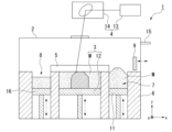
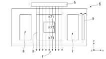
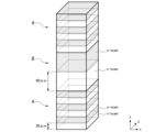
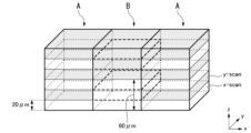
- FIG. 1 is a schematic diagram showing an example of the configuration of a laminated structure manufacturing apparatus applicable to the present embodiment. It is a top view of the modeling stage with which the manufacturing apparatus of the laminated structure applicable to this embodiment is equipped. It is a figure for demonstrating the minimum angle among the angles which the scanning direction of an energy ray and the direction of the gas flow F make in this embodiment. It is a figure for explaining an example of the manufacturing method of a laminated structure. It is a figure for explaining an example of the manufacturing method of a laminated structure. It is a figure for explaining the crystal structure of the layered structure obtained by the manufacturing method of the layered structure of this embodiment. It is a figure for explaining the crystal structure of the layered structure obtained by the manufacturing method of the layered structure of this embodiment.
- FIG. 1 is a diagram of a laminated structure produced in Examples 1 and 2.
- FIG. 2 is a diagram showing the results of observing the crystal orientation map (IPF map) and pole figure of the laminated structures produced in Examples 1 and 2.
- FIG. 2 is a diagram showing the results of observing the crystal structure of the laminated structures produced in Examples 1 and 2.
- FIG. 7 is a diagram showing the results of observing the crystal structure of the laminated structure produced in Experimental Example 3.
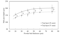
- FIG. 7 is a diagram showing the relationship between the deposited thickness of the powder bed and the depth of the melt pool in Example 3.
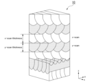
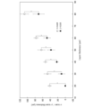
- FIG. 4 is a diagram showing the results of observing the residual thickness of the x-scan layer (x-scan thickness) and the residual thickness of the y-scan layer (y-scan thickness) in Experimental Example 4.
- FIG. 4 is a diagram showing the results of observing the residual thickness of the x-scan layer (x-scan thickness) and the residual thickness of the y-scan layer (y-scan thickness) in Experimental Example 4.
- FIG. 7 is a diagram of a laminated structure produced in Experimental Example 5.
- FIG. 7 is a diagram showing the results of observing the crystal structure of the laminated structure produced in Example 5.
- crystal planes are indicated as follows.
- the crystal orientation is shown as follows. [001]: When considering the axis as fixed, ⁇ 001>: When considering the x, y, z, etc. axes without fixing them, the orientation of the crystal cannot be distinguished depending on the viewing direction. (001) etc. represent Miller indices. " ⁇ " indicating a numerical range means that the numerical values written before and after it are included as lower and upper limits.
- the method for manufacturing a laminated structure of the present invention includes providing a gas flow parallel to the surface of the powder bed along the surface of the powder bed on which raw material powder is deposited; and energy rays in a first direction parallel to the surface of the powder bed. irradiation while scanning to form a first melted and solidified layer; irradiation while scanning with an energy beam in a second direction parallel to the surface of the powder bed and intersecting the first direction to form a second melted and solidified layer.
- a method for manufacturing a laminated structure including one or more first and second melt-solidified layers each, and including a crystal structure in which a plurality of layers are stacked in the thickness direction;
- the first melt-solidified layer When forming the first melt-solidified layer, the first deposited thickness of the powder bed and the first heat input of the energy beam irradiated to the powder bed are adjusted so that the stacked thickness of the first melt-solidified layer and the first melt-solidified layer are adjusted. Control the penetration depth of the solidified layer;
- the second deposited thickness of the powder bed and the second heat input of the energy beam irradiated to the powder bed are adjusted so that the stacked thickness of the second melt-solidified layer and the second melt-solidified layer are adjusted.
- the first heat input is controlled by adjusting the angle ⁇ 1 between the first direction and the gas flow direction;
- the second heat input is controlled by adjusting the angle ⁇ 2 between the second direction and the gas flow direction;
- the remaining thickness of the first melt-solidified layer and the remaining thickness of the second melt-solidified layer in the crystal structure are controlled.
- the stacking thickness of the molten solidified layer formed by the irradiation of the energy rays and the penetration depth of the molten solidified layer can be adjusted.
- the laminated thickness of the first melt-solidified layer and the penetration depth of the first melt-solidified layer can be controlled.
- the laminated thickness of the second melt-solidified layer and the penetration depth of the second melt-solidified layer can be controlled.
- first heat input amount and the second heat input amount are the minimum angle ⁇ 1 among the angles formed between the first direction and the gas flow direction, and the minimum angle ⁇ 1 among the angles formed between the second direction and the gas flow direction. By adjusting ⁇ 2, each can be controlled.
- the powder bed is irradiated with the energy rays and the raw material powder is Spatter and fume generated during melting flow in the direction of the gas flow, causing attenuation of energy rays scanning in that direction, reducing the amount of heat. Furthermore, since the gas flows in the longitudinal direction of the molten pool, heat dissipation of the molten raw material is promoted. Therefore, by changing the minimum angle ⁇ ( ⁇ 1, ⁇ 2) between the scanning direction of the energy beam and the gas flow direction, the amount of heat input of the energy beam irradiated to the powder bed can be adjusted. As a result, it is possible to control the penetration depth of the melted and solidified layer formed by the energy beams scanned in a desired direction.
- the crystal structure of the laminated structure can be easily controlled.
- the first heat input amount and the second heat input amount may be each controlled by a scanning strategy such as the output of the energy beam, the scanning speed, the scanning interval, and the irradiation position.
- a scanning strategy such as the output of the energy beam, the scanning speed, the scanning interval, and the irradiation position.
- the stacking thickness of the powder bed for forming the molten solidified layer constituting the crystal structure by adjusting the stacking thickness of the powder bed for forming the molten solidified layer constituting the crystal structure, the stacking thickness of the molten solidified layer formed by energy ray irradiation and the thickness of the molten solidified layer can be adjusted.
- the penetration depth can be controlled.
- the stacked thickness of the first melt-solidified layer can be controlled by adjusting the stacked thickness of the first stacked layer of the powder bed.
- the layer thickness of the second melt-solidified layer can be controlled.
- the first stacked layer thickness and the second stacked layer thickness of the powder bed may be the same or different.
- the deposition thickness of the powder bed for the molten solidified layer to be controlled and the thickness of the powder bed adjacent to the molten solidified layer above and below in the thickness direction of the molten solidified layer to be controlled are
- the deposited thickness of the powder bed for the melt-solidified layer can be varied from one another. Therefore, the remaining thickness in the laminated structure can be changed more precisely between the melt-solidified layer to be controlled and the melt-solidified layers that are vertically adjacent to it in the thickness direction.
- the above-mentioned “deposition thickness of the powder bed” is the thickness in the direction perpendicular to the powder bed, and the “thickness direction of the melt-solidified layer” can also be rephrased as the direction perpendicular to the powder bed.
- the crystal orientation can be adjusted by changing the deposited thickness of the powder bed, so the crystal structure of the laminated structure can be controlled more easily. Furthermore, for example, by sequentially stacking the melt-solidified layers in the thickness direction while changing the deposition thickness of the powder bed for each melt-solidified layer, further diversity can be achieved in the manner of controlling the crystal structure of the laminated structure. may be provided.
- one of the minimum angle ⁇ 1 of the angles formed between the first direction and the gas flow direction and the minimum angle ⁇ 2 of the angles formed between the second direction and the gas flow direction is set to 45
- the angle may be adjusted to be between 0° and 90°, and the other angle may be adjusted between 0° and 45°.
- the penetration depth of the molten solidified layer formed in the scanning direction where the heat input is small is smaller than the penetration depth of the molten solidified layer formed in the scanning direction where the heat input is large.
- the residual thickness of the molten solidified layer formed in the scanning direction where the heat input is smaller than that formed in the scanning direction where the heat input is large. The remaining thickness of the melt-solidified layer becomes smaller.
- the amount of heat input when irradiating the energy beam while scanning in the first direction can be adjusted without changing the output and scanning speed of the energy beam.
- the amount of heat input when irradiating the energy beam while scanning in the second direction can be adjusted to the same degree.
- the penetration depth of the first melt-solidified layer and the penetration depth of the second melt-solidification layer become approximately the same, and in the laminated structure formed by alternately scanning in the first direction and scanning in the second direction.
- the residual thickness of the first melt-solidified layer and the residual thickness of the second melt-solidified layer are approximately the same.
- the remaining thickness of the melt-solidified layer to be controlled can be adjusted to an arbitrary thickness.
- further diversity can be provided in the manner of controlling the crystal structure of the laminated structure.
- the method for manufacturing a laminated structure of the present invention includes a first melt-solidified layer and a second melt-solidified layer, and the first melt-solidified layer and the second melt-solidified layer are alternately laminated in the thickness direction.
- a laminated structure containing a crystalline structure is obtained, but the laminated structure includes only a first melted and solidified layer, a crystalline structure in which a plurality of layers are stacked in the thickness direction, and only a second melted and solidified layer, It may further include a crystal structure in which a plurality of layers of these are stacked in the thickness direction.
- the first deposited thickness of the powder bed increases when forming the first melted and solidified layer.
- the lamination thickness of the first melt-solidified layer is controlled to be large by adjusting as follows;
- the penetration depth of the first melt-solidified layer is controlled by adjusting to increase the first heat input of the energy beam irradiated to the powder bed.
- the thickness of the second molten solidified layer becomes large; and control the stacked thickness of the second molten solidified layer to become small by adjusting the second deposition thickness of the powder bed to be small when forming the second molten solidified layer;
- the second heat input amount of the energy beam irradiated to the powder bed is adjusted to be small, and the penetration depth of the second molten solidified layer is controlled to be small.
- the remaining thickness of the second melt-solidified layer becomes thinner, so when the energy beam is irradiated while scanning in the first direction to form the first melt-solidified layer, the second melt-solidified layer is overwritten. .
- the method for manufacturing a laminated structure of the present invention provides energy in a third direction that is parallel to the surface of the powder bed and intersects with the first and second directions, respectively.
- a third molten solidified layer is formed by irradiation while scanning a line, and a crystal structure including at least one third molten solidified layer and in which multiple first to third molten solidified layers overlap in the thickness direction is formed.
- a laminated structure further including the above may be manufactured. Thereby, further diversity can be imparted to the control of the crystal structure of the laminated structure.
- FIG. 1 is a schematic diagram showing an example of the configuration of a laminated structure manufacturing apparatus applicable to this embodiment.
- FIG. 2 is a plan view of a modeling stage included in the laminated structure manufacturing apparatus applicable to this embodiment.
- a laser is used as the energy beam
- the first direction is the x-axis direction shown in FIGS. 1 and 2
- the second direction is the x-axis direction shown in FIGS. 1 and 2.
- An example of the case where the direction is the y-axis will be described below.
- laser scanning along the x-axis direction is referred to as "x-scan”
- laser scanning along the y-axis direction is referred to as "y-scan”.
- a laminated structure manufacturing apparatus (hereinafter simply referred to as "manufacturing apparatus") 1 includes a chamber 2, a powder bed 3, an irradiation section 4, a gas flow generation section 5, and a modeling stage 6 (not shown). and a control section.
- the chamber 2 is a housing in which a laminated structure is formed.
- a shield gas supply pipe 15 is connected to the upper side of the chamber 2 .
- the shield gas supply pipe 15 introduces shield gas into the chamber 2 .
- the shielding gas is a gas supplied into the chamber during laser irradiation.
- an inert gas is preferable, and argon gas is more preferable.
- a gas other than an inert gas such as oxygen or hydrogen that reacts with the raw material may be used as the shielding gas.
- the raw material powder is not particularly limited.
- the raw material powder include powders of various metals such as magnesium, calcium, chromium, copper, iron, manganese, molybdenum, cobalt, nickel, hafnium, niobium, titanium, and aluminum, and alloys thereof.
- the ceramic powder include powders of silicides, oxides, nitrides, carbides, borides, and the like of the above metals.
- a mixed powder of ceramic powder and powder of the above-mentioned metals, alloys, and their silicides, oxides, nitrides, carbides, borides, etc. may be used as the raw material powder.
- the particle size of the raw material powder is not particularly limited.
- the particle size can be, for example, about 10 to 200 ⁇ m.
- a modeling stage 6 is provided within the chamber 2.
- the modeling stage 6 includes a powder bed 3, a storage section 7, a collection section 8, and a recoater 9.
- the recoater 9 reciprocates along the x-axis direction shown in the figure.
- the storage section 7 has a raw material powder M to be supplied to the powder bed 3 and a first lifting platform 11 on which the raw material powder is placed. As the first elevating table 11 rises, the raw material powder is deposited above the upper surface of the modeling stage 6. The deposited raw material powder is moved along the x-axis direction by a recoater 9 and supplied to the powder bed 3. The surface of the raw powder M of the powder bed 3 (the surface of the powder bed) is made flat by the recoater 9.
- the recoater 9 and the first lifting platform 11 are electrically connected to a control section (not shown). Therefore, the recoater 9 and the first lifting platform 11 can supply the raw material powder in the storage section 7 to the powder bed 3 according to instructions from the control section.
- the powder bed 3 includes a raw material powder M, a second lifting table 12 on which the raw material powder M is placed, and a base plate (not shown) placed on the surface of the second lifting table 12.
- the second lifting platform 12 is movable along the z-axis direction. Therefore, the powder bed 3 of the raw powder M is movable in the vertical direction, that is, in the z-axis direction within the chamber 2.
- the second lifting platform 12 descends ⁇ h in the z-axis direction
- the raw material powder M from the storage section 7 is moved by the recoater 9, and a powder layer of the raw material powder M having a thickness of ⁇ h forms a powder bed.
- the descending distance ⁇ h of the second lifting platform 12 in the z-axis direction corresponds to the deposited thickness ⁇ h of the powder bed for each melt-solidified layer of the laminated structure.
- the second lifting platform 12 is electrically connected to a control section (not shown). Therefore, the second lifting table 12 can control the deposition thickness ⁇ h of the powder bed 3 according to instructions from the control unit.
- the irradiation unit 4 has a laser oscillator 13 and an optical system 14.
- the laser oscillator 13 is not particularly limited as long as it is a laser irradiation source.
- the optical system 14 reflects the laser from the laser oscillator 13 and irradiates the raw material powder M on the powder bed 3 with the laser while scanning it.
- the optical system 14 is composed of one or more reflecting mirrors. Further, the laser oscillator 13 and the optical system 14 are both electrically connected to a control section (not shown).
- the irradiation unit 4 controls the direction in which the laser is reflected by the optical system 14 according to instructions from a control unit (not shown). Then, the irradiation unit 4 controls the reflection direction of the laser using the optical system 14, and scans and irradiates the laser.
- the irradiation unit 4 irradiates the raw material powder on the powder bed 3 with a laser to sinter or melt and solidify the raw material powder M at the irradiation position. Therefore, a molten solidified layer of a sintered raw material powder or a molten solidified layer of a molten solidified raw material powder can be formed on the powder bed 3.
- the gas flow generator 5 provides a gas flow F near the surface of the powder bed 3 along the surface. Therefore, in addition to controlling the crystal structure, the gas flow generator 5 can also remove spatter, fumes, etc. generated during laser irradiation to the melted and solidified layer using the gas flow F.
- the gas flow generating section 5 is electrically connected to a control section (not shown).
- the control section is electrically connected to the laser oscillator 13 and the optical system 14. Therefore, the gas flow generation unit 5 can change the direction of the gas flow F with respect to the scanning direction of the energy beam (laser) that is irradiated to form a molten solidified layer whose crystal structure is to be controlled. Further, the gas flow generating section 5 can adjust the flow rate of the gas flow F according to instructions from a control section (not shown).
- the flow rate of the gas flow F on the surface of the powder bed 3 is preferably 0.1 to 10 m/s, more preferably 1.0 to 5.0 m/s.
- the composition of the gas flow F is preferably the same as that of the shielding gas.
- examples of the composition include a gas containing at least one selected from the group consisting of helium, nitrogen, neon, argon, and xenon.
- the gas flow may contain one type of these gas components alone, or may contain two or more types in combination.
- the gas flow generation unit 5 can change the direction of the gas flow F by changing the position and orientation of the gas flow generation unit 5 with respect to the modeling stage 6.
- a gas other than an inert gas such as oxygen or hydrogen that reacts with the raw material is used as a shielding gas
- a gas other than an inert gas such as oxygen or hydrogen may be used as the gas flow. It is also possible. In this case, there is a possibility that the raw material powder and the gas flow will react and impart new properties to the laminated structure.
- the control unit may include, for example, a central processing unit (CPU), a memory, and a hard disk drive.
- the hard disk drive may include a CAD application and a CAM (Computer Aided Manufacturing) application.
- the control unit can create three-dimensional structural data of a laminated structure having a desired shape.
- a control unit creates processing condition data based on the three-dimensional structure data. Processing condition data can be created for each melt-solidified layer.
- a control unit controls the irradiation unit 4 (laser oscillator 13 and optical system 14) based on processing condition data, and can adjust laser output, scanning speed, scanning interval, and irradiation position.
- the recovery section 8 has a third lifting platform 16.
- the third lifting platform 16 is movable along the z-axis direction.
- excess raw material powder can be recovered into the recovery section 8 .
- the raw material powder remaining on the modeling stage 6 can be moved to the recovery section 8 by the recoater 9 and recovered.
- a gas flow F parallel to the surface of the powder bed is provided along the surface of the powder bed on which the raw material powder is deposited, and a gas flow F is provided in the x-axis direction parallel to the surface of the powder bed ( A laser is irradiated while scanning (x-scan) in the first direction) to form an x-scan layer (first melted solidified layer), and the y-axis direction is parallel to the surface of the powder bed and perpendicular to the x-axis direction.
- a laser while scanning (y-scan) in the (second direction) to form a y-scan layer (second melted solidified layer), each including one or more x-scan layers and one or more y-scan layers;
- This is a method for manufacturing a laminated structure including a crystal structure in which multiple layers are stacked in the thickness direction; when forming an x-scan layer, the deposition thickness of the powder bed (first deposition thickness)
- the stacking thickness and penetration depth of the x-scan layer are controlled by adjusting the heat input amount (first heat input amount) of the laser irradiated to the bed; when forming the y-scan layer, the deposition thickness of the powder bed is adjusted.
- the amount of heat input in y-scan is controlled by adjusting the smallest angle ⁇ x ( ⁇ 1) between the x-axis direction and the direction of gas flow F; The smallest angle ⁇ y ( ⁇ 2) among the angles formed with the direction is adjusted and controlled; the residual thickness of the x-scan layer and the residual thickness of the y-scan layer in the crystal structure are controlled.
- a laminated structure is obtained by stacking a plurality of melted and solidified layers formed by irradiating a powder bed of raw material powder with a laser as an energy beam. Based on the CAD data of the laminated structure, the formation of the powder bed, the formation of the melt-solidified layer, and the lamination of the melt-solidified layer are repeated an arbitrary number of times.
- the first layer formed by the first laser irradiation that is, the lowermost melted and solidified layer is formed on the base plate (not shown) on the surface of the second lifting table 12. (omitted). Thereafter, melt-solidified layers are sequentially laminated on top of the first melt-solidified layer.
- shielding gas Before laser irradiation, it is preferable to supply shielding gas from the shielding gas supply pipe 15 to the inside of the chamber 2 and the lower cavities of the first lifting table 11, the second lifting table 12, and the third lifting table 16. .
- This fills the shielding gas. Therefore, in the presence of a sufficient amount of shielding gas, heat can be supplied to the raw material powder using a laser to form a molten solidified layer.
- an inert gas is used as a shielding gas, if the shielding gas is not filled inside the chamber 2, the raw material powder and gases other than the shielding gas will react, making it difficult to obtain the desired properties of the laminated structure. .
- the shielding gas If a gas other than an inert gas such as oxygen or hydrogen that reacts with the raw material is used as the shielding gas, if the shielding gas is not filled inside the chamber 2, it will be difficult for the raw material powder and the shielding gas to react sufficiently. , it is difficult to obtain a metal structure that can impart new properties to laminated structures.
- an inert gas such as oxygen or hydrogen that reacts with the raw material
- x-scans and y-scans can be repeatedly and alternately executed to stack a plurality of melted and solidified layers in the z-axis direction.
- the direction of the gas flow F of the shielding gas is different between the x-scan and the y-scan.
- the minimum angle between the scanning direction of energy rays in x-scan and the direction of gas flow F is ⁇ x
- the minimum angle between the scanning direction of energy rays in y-scan and the direction of gas flow F is ⁇ x.
- the laminated structure 10 can be manufactured by forming the 2n-1th melt-solidified layer by y-scan, and forming the 2n-th melt-solidified layer by x-scan.
- n natural number
- the 2n-1th melt-solidified layer is a melt-solidified layer formed by y-scan (hereinafter sometimes referred to as "y-scan layer”)
- the 2n-th melt-solidified layer is This is a melt-solidified layer formed by x-scan (hereinafter sometimes referred to as "x-scan layer").
- the raw material powder in the storage section 7 is supplied to the surface of the second lifting platform 12 by the recoater 9, and the powder bed with the deposited thickness ⁇ h is formed in the 2n-2nd layer. Formed above the melt-solidified layer.
- This powder bed having a deposited thickness ⁇ h is irradiated with a laser to form a 2n-1th melted and solidified layer.
- the powder layer is sintered or melt-solidified by laser scanning. As a result, the 2n-1th melt-solidified layer is laminated above the 2n-2nd melt-solidified layer.
- a powder bed with a deposition thickness of ⁇ h is formed above the 2n-1th melted and solidified layer. Then, the upper side of the powder bed formed on the surface of the 2n-1th melted and solidified layer is irradiated with a laser. Then, the powder layer is sintered or melted and solidified by laser scanning to form a 2nth melted and solidified layer, and the 2nth melted and solidified layer is laminated above the 2n-1th melted and solidified layer.
- a laminated structure can be manufactured by stacking a plurality of melt-solidified layers.
- x-scan and y-scan it is possible to manufacture a laminate structure 10 having a crystal structure in which x-scan layers and y-scan layers are repeatedly stacked.
- the laminated structure 10 is recovered from the chamber 2 while being placed on the base plate.
- FIG. 5 shows a case where the direction of gas flow F is perpendicular to the direction of x-scan, and the direction of gas flow F is parallel to the direction of y-scan.
- ⁇ x is 90° and ⁇ y is 0°.
- the laser is influenced by the gas flow F, and the amount of heat input to the laser powder bed during y-scan is reduced to the laser powder bed during x-scan. is attenuated more than the heat input.
- the penetration depth of the molten solidified layer is smaller than in the x-scan, and the thickness of the y-scan layer remaining in the crystal structure becomes smaller than the thickness of the x-scan layer.
- the direction of the gas flow F is changed so as to satisfy the relationship ⁇ x> ⁇ y.
- the penetration depth of the y-scan layer to be controlled in the crystal structure becomes smaller than the penetration depth of the x-scan layer.
- the remaining thickness of the y-scan layer can be varied in the crystal structure contained in the laminated structure.
- the crystal orientation of the crystal structure and the orientation of the crystal orientation can be adjusted by intentionally changing the direction of the gas flow F, so that the crystal structure of the laminated structure can be easily adjusted. Can be controlled. At this time, by changing the flow rate of the gas flow F in addition to changing the direction of the gas flow F, the crystal structure of the laminated structure can be changed more precisely.
- the deposition thickness of the powder bed for the y-scan layer is changed to the deposition thickness of the powder bed for forming the adjacent x-scan layer. It is also effective.
- the residual thickness of the y-scan layer is can be precisely changed.
- the crystal orientation of the crystal structure and the orientation of the crystal orientation can be adjusted by changing the deposited thickness of the powder bed, so the crystal structure of the laminated structure can be easily controlled.
- the deposition thickness of the x-scan layer and the deposition thickness of the y-scan layer are the same, and these deposition thicknesses are set to the penetration depth "Sx" of the molten solidified layer in the x-scan and the deposition thickness of the y-scan layer.
- the y-scan layer can also be intentionally left in the laminated structure by making the difference "Sx-Sy" larger than the difference "Sx-Sy" from the penetration depth "Sy” of the melt-solidified layer.
- the deposition thickness of the x-scan layer and the deposition thickness of the y-scan layer are made the same, and these deposition thicknesses are calculated based on the penetration depth "Sx" of the melted solidified layer in the x-scan and By making the difference from the penetration depth "Sy" of the solidified layer smaller than "Sx-Sy", the y-scan layer can be overwritten and erased with the x-scan layer.
- the penetration depth "Sx" of the molten solidified layer in the x-scan and the penetration depth "Sy” of the molten solidified layer in the y-scan can be determined by observing the metal structure of the modeled object, as shown below. .
- Measurement method of penetration depth of molten solidified layer (melt depth or molten pool depth)
- the metal structure that has been polished to a mirror finish by sandpaper polishing and buffing is etched, and then observed and measured using a microscope.
- the laser (energy ray) scanning direction of the observed metal structure can be determined from the overlapping direction of the molten pool.
- the crystal structure can be controlled not only in the stacking direction (Z direction) but also in the XY plane of the molten solidified layer.
- the deposited thickness ⁇ h of the powder bed (powder layer) is small, a laser is irradiated to an arbitrary location to form a melted solidified layer, and a powder bed is provided on top of it, the thin powder bed of the previous layer
- the remaining thickness can be locally increased. In this way, it is also possible to control the crystal structure within the plane of the melt-solidified layer.
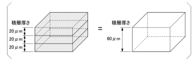
- a crystal structure B having a lamination thickness ⁇ h of 60 ⁇ m may be formed by irradiating the laser in the third lamination step without irradiating the laser in the first and second lamination steps.
- a laminated structure of the present embodiment it is possible to easily control the crystal structure contained in a laminated structure having an arbitrary three-dimensional structure, and it is possible to control an arbitrary crystal orientation.
- Such laminated structures have an advantageous effect on various product groups in a wide range of industrial fields. For example, advantages are provided such as the ability to obtain a crystalline structure that exhibits desired mechanical properties and the ability to satisfy various property requirements for laminated structures.
- the y-scan layer tends to disappear from the laminated structure. Therefore, even if x-scan and y-scan are performed alternately, the y-scan layer can be intentionally erased from the laminated structure, resulting in a laminated structure with the same crystal structure as when only x-scan is performed. Structures can be manufactured.
- the lamination direction that is, the z-axis direction
- a single-crystal-like structure of ⁇ 001> appears along the line.
- the lamination direction that is, the z-axis direction
- a lamellar crystal structure consisting of two types of ⁇ 001> and ⁇ 011> is developed along the line.
- the deposition thickness ⁇ h of the powder bed for each melt-solidified layer of the laminated structure can be changed. Ta.
- the powder bed is formed again without irradiating the powder bed with a laser, so that the deposition thickness of the powder bed can be reduced.
- ⁇ h may be changed. For example, as shown in FIG. 8, when the lamination thickness ⁇ h is 20 ⁇ m, the lamination thickness is ⁇ h may be set to 60 ⁇ m.
- the melt-solidified layer whose crystal structure is to be controlled may be a plurality of melt-solidified layers, or may be a single melt-solidified layer.
- the plurality of melted and solidified layers may all be formed with energy rays in the same scanning direction, or may be formed with energy rays in mutually different scanning directions.
- the laser scanning direction is two directions, the x direction and the y direction, has been described as an example, but the present invention is not limited to this.
- the laser scanning direction may be three or more directions. Specifically, when the laser scanning direction is three directions, the smallest angle among the angles formed by the first direction and the second direction, the smallest angle among the angles formed between the second direction and the third direction, Also, the minimum angle between the third direction and the first direction may be 60°.
- the smallest angle among the angles formed by the first direction and the second direction, the smallest angle among the angles formed between the second direction and the third direction, and the third direction may each be 45°.
- the present invention includes the following embodiments (1) to (5) when the first to fifth melt-solidified layers are A, B, C, C, D, and E, respectively.
- (1) A modeling method in which layers A and B are alternately laminated over the entire laminate structure.
- Bottom layer side ABABABAB...ABABABAB: Top layer side
- Layers A to E are layered over the entire laminate structure.
- a modeling method that repeatedly stacks layers Bottom layer side: ABCDE... ABCDE: Top layer side
- Bottom layer side ABCABCABC... ⁇ ABCABCABC: Top layer side
- Bottom layer side AAABBBAAA... BBBAAABBB: Top layer side
- Laminated structure A modeling method that repeatedly laminates continuous A layer, continuous B layer, and continuous C layer over the entire object
- Bottom layer side AABBCC...AABBCC: Top layer side
- ⁇ x 90°
- ⁇ y 0°
- the remaining thicknesses of the x-scan layer and the y-scan layer in the crystal structure included in the laminated structure can be changed by the constituent requirements ( ⁇ ) and ( ⁇ ). Moreover, further diversity can be provided in the manner of controlling the crystal structure of the laminated structure. Constituent requirements ( ⁇ ) and ( ⁇ ) can be used in combination when manufacturing one laminated structure. When the constituent elements ( ⁇ ) and ( ⁇ ) are adopted, the effects of each constituent element are considered to be obtained in a superimposed manner.
- constituent elements ( ⁇ ) and ( ⁇ ) may be adopted successively to form x-scan layers and y-scan layers that are adjacent to each other; multiple melt-solidified layers that are not adjacent to each other Constituent requirements ( ⁇ ) and ( ⁇ ) may be adopted intermittently in order to form discrete x-scan layers and y-scan layers via.
- the laser is scanned along the x-axis direction to form the 2n-1 layer, and the laser is scanned along the y-axis direction to form the 2n-th layer.
- the 2n-1 layer becomes an x-scan layer
- the 2n layer becomes a y-scan layer.
- the scanning mode may be either reciprocating or unidirectional.
- the scanning direction of the laser is fixed and the direction of the gas flow F is changed, but the invention is not limited to this.
- the direction of the gas flow F may be fixed and the scanning direction of the laser may be changed.
- Example> A powder having the following composition was prepared as a raw material powder using a gas atomization method. Composition: 18Cr-14Ni-2.5Mo-0.03C-65.47Fe (mass%). The particle size of the obtained raw material powder used was 53 ⁇ m or less.
- the manufacturing conditions for the laminated structure are as follows. Equipment used: EOS M290 (manufactured by EOS); Laser scanning: x-scan and y-scan are performed alternately. Laser scanning was performed back and forth in each of the x-scan and y-scan (see Figures 4 and 5); Lamination thickness: 20 ⁇ m or 60 ⁇ m; Output: 250W; Scanning speed of x-scan and y-scan: 800mm/s; Scan interval of x-scan and y-scan: 0.08 mm.
- Equipment used EOS M290 (manufactured by EOS)
- Laser scanning x-scan and y-scan are performed alternately. Laser scanning was performed back and forth in each of the x-scan and y-scan (see Figures 4 and 5); Lamination thickness: 20 ⁇ m or 60 ⁇ m; Output: 250W; Scanning speed of x-scan and y-scan: 800mm/s; Scan interval
- the gas flow conditions of the gas flow generator 5 are as follows. Gas type of gas flow: Argon gas; Direction of gas flow: Argon gas was flowed along the y-axis when performing the y-scan. The y-scan layer is the molten solidified layer to be controlled. Gas flow velocity: The flow velocity on the surface of the powder bed 3 in the modeling stage 6 was measured using a vane type anemometer Testo 440 dP (manufactured by Testo) (see FIG. 2). Measurements were taken at the following three locations P1, P2, and P3 on a plane passing through the center of the powder bed 3 in the x-axis direction and along the y-axis direction.
- - P1 A position located at the center of the powder bed 3 in the x-axis direction, approximately 90 mm away from the gas flow generator 5 in the y-axis direction, and approximately 8 mm away from the surface of the powder bed 3 in the z-axis direction.
- - P2 A position located at the center of the powder bed 3 in the x-axis direction, approximately 135 mm from the gas flow generating section 5 next to P1 in the y-axis direction, and approximately 8 mm away from the surface of the powder bed 3 in the z-axis direction.
- the method for evaluating the crystal structure of a laminated structure is as follows. [Method for evaluating the crystal structure of laminated structures] Scanning electron microscopy (FE-SEM) and electron backscatter diffraction (EBSD) were used. The laminated structure was cut in the xz plane and the yz plane, polished with emery paper up to #4000, and polished with colloidal silica to give a mirror finish. Thereafter, etching was performed using an etching solution consisting of 21% HF, 29% HNO 3 and 50% H 2 O. Thereafter, the crystal orientations of the xz plane and yz cross section were observed and analyzed. JIB-4610F (manufactured by JEOL) was used as the FE-SEM. As the EBSD, Nordlys Max3 (manufactured by Oxford Instruments) was used.
- FE-SEM scanning electron microscopy
- EBSD electron backscatter diffraction
- FIG. 10 shows a crystal orientation map and a pole figure. As shown in FIG. 10(a), a specific lamellar structure was confirmed in which ⁇ 011> crystal orientation was expressed with respect to the z-axis (stacking direction), and ⁇ 001> was expressed at equal intervals.
- FIG. 10 shows a crystal orientation map and a pole figure. As shown in FIG. 10(b), a ⁇ 001> single crystal-like structure was confirmed with respect to the z-axis (stacking direction).
- FIG. 11 shows the results of observing the crystal structure of the laminated structures produced in Experimental Examples 1 and 2.
- the arrows in FIG. 11 indicate the temperature gradient associated with dissolution. It is generally believed that a cell structure (solidification structure) grows in a direction close to this temperature gradient, and the direction of extension of this cell structure is crystallographically parallel to the ⁇ 100> direction.
- the laminated structure was cut, polished, and etched under the same conditions as in the above [Method for evaluating the crystal structure of a laminated structure], and the crystal orientation of the xz plane and yz cross section was observed and measured.
- the melting depth of the x-scan layer was determined by modeling a laminated structure so that the last layer (top layer) ended with the x-scan, and observing the yz plane.
- the melting depth of the y-scan layer was determined by modeling the laminated structure so that the last layer (top layer) ended with the y-scan, and observing the xz plane.
- the conditions for producing the laminated structure were the same as in Experimental Examples 1 and 2, except that the laminated thickness was changed as described above.
- FIG. 12 shows the results of observing the crystal structure of the laminated structure produced in Experimental Example 3.
- FIG. 13 shows the relationship between the deposition thickness of the powder bed and the depth of the melt pool in Example 3.
- the depth of the molten pool was measured by the method for measuring the penetration depth of the molten solidified layer (melting depth or molten pool depth) described above.
- the melting depth of the y-scan layer is equal to the melting depth of the x-scan layer. It became smaller than Sa.
- the "Student's t-test” consists of a significant difference determination based on the P value and a confidence interval of the population mean difference. Significant differences were determined based on P values, based on the averages and standard deviations of the two populations, and whether the population means of the two groups (two groups) could be said to be equal. Specifically, 10 melt depths Sx and 10 Sy were measured, and a t-test (two-tailed test) was performed for two samples with equal variance using the function "T.TEST" of "Microsoft Excel for Microsoft 365". ) was carried out.
- ⁇ Experiment example 4> The remaining thickness of the x-scan layer (x-scan thickness) and the remaining thickness of the y-scan layer (y-scan thickness) when the lamination thickness was changed to 20 ⁇ m, 30 ⁇ m, 40 ⁇ m, 50 ⁇ m, 60 ⁇ m, and 80 ⁇ m. ) were measured using the polishing and etching conditions in the above [Method for evaluating the crystal structure of a laminated structure] and the above [Method for measuring the penetration depth (melt depth or molten pool depth) of the molten solidified layer]. did.
- the observation points are set at 45 degrees to the x and y directions as shown in Figure 9. A cross section parallel to the z direction was also observed.
- the conditions for producing the laminated structure were the same as in Experimental Examples 1 and 2, except that the laminated thickness was changed as described above.
- the y-scan was not overwritten by the x-scan, and a crystal structure with crystal orientation biased toward each of the x-scan and y-scan was confirmed. As a result, two types of crystal structures remained in the laminated structure and appeared along the lamination direction.
- the lamination thickness was 40 ⁇ m or more
- the y-scan was not overwritten by the x-scan, and a crystal structure with crystal orientation biased toward each of the x-scan and y-scan was confirmed. Furthermore, it was confirmed from the y-scan crystal structure that adjacent molten pools were in contact with each other. More contact points were observed as the layer thickness increased.
- any raw material powder can be melted by adjusting the process parameters of the heat source (energy beam) output, scan speed, and scan strategy.
- the above experimental example is an experimental result for a stainless steel alloy, but any raw material that can be melted by a laser can produce the same effects as the stainless steel alloy.
- SYMBOLS 1 Laminated structure manufacturing device, 2... Chamber, 3... Powder bed, 4... Irradiation section, 5... Gas flow generation section, 6... Modeling stage, 7... Storage section, 8... Recovery section, 9... Recoater, 10 ... Laminated structure, 11... First elevating table, 12... Second elevating table, 13... Laser oscillator, 14... Optical system, 15... Shield gas supply pipe, 16... Third elevating table, M... Raw material powder.
Landscapes
- Engineering & Computer Science (AREA)
- Chemical & Material Sciences (AREA)
- Manufacturing & Machinery (AREA)
- Materials Engineering (AREA)
- Automation & Control Theory (AREA)
- Physics & Mathematics (AREA)
- Plasma & Fusion (AREA)
- Powder Metallurgy (AREA)
Abstract
積層構造物中の結晶組織の制御が容易な積層構造物の製造方法を提供することを目的とする。パウダーベッドの表面と平行なガスフローを設け、第1方向にエネルギー線を走査しながら照射して第1溶融固化層を形成し、第1方向と交差する第2方向にエネルギー線を走査しながら照射して第2溶融固化層を形成し、パウダーベッドの第1堆積厚さと、エネルギー線の第1入熱量とを調整して、第1溶融固化層の積層厚さ及び第1溶融固化層の溶け込み深さを制御し、パウダーベッドの第2堆積厚さと、エネルギー線の第2入熱量とを調整して、第2溶融固化層の積層厚さ及び第2溶融固化層の溶け込み深さを制御し、第1方向とガスフローの方向とのなす角度α1を調整して第1入熱量を制御し、第2方向とガスフローの方向とのなす角度α2を調整して第2入熱量を制御して、結晶組織における第1溶融固化層の残存厚さと第2溶融固化層の残存厚さとを制御する、積層構造物の製造方法を選択する。
Description
本発明は、積層構造物の製造方法に関する。
付加製造技術のようにエネルギー線を用いて積層構造物を製造することがある。例えば、任意のCAD(Computer Aided Design)データに基づいてレーザの照射により得られる金属層を順次積層し、三次元構造物として任意の形状の積層構造物を製造できる。付加製造技術は、航空機関連部材を含む産業機器分野や医療機器分野等に適用され、有望な技術として注目されている。近年、積層構造物に所望の機械的特性を付与するために、積層構造物の結晶組織を制御することが提案されている。例えば、結晶組織の制御により機械的強度、弾性率を制御できる。他にも、優先的な結晶方位を持つ結晶組織によれば、ヤング率、降伏応力、耐疲労性等の異方性を積層構造物に付与できる。
特許文献1~3では、結晶組織の制御のための手法としてレーザのスキャン速度、レーザ出力、ピッチ幅、スキャンストラテジー等のプロセスパラメータを調整することが提案されている。
特許文献1では、βチタン合金において低弾性率化を実現するために、溶融工程での走査方向を調整することで、結晶配向性を制御することが提案されている。
特許文献2では、スキャンストラテジーとレーザパワーとを組み合わせ、レーザ光および/またはアーク放電の照射方向とパワーとを制御することによって、積層方向に対し単結晶様の組織を形成することが提案されている。
特許文献3では、指向性エネルギー源からのビームを誘導し、堆積及び融合工程を行い、別の外部熱制御装置により再融解及び凝固をすることで、単結晶様組織を得ることが提案されている。
特許文献2では、スキャンストラテジーとレーザパワーとを組み合わせ、レーザ光および/またはアーク放電の照射方向とパワーとを制御することによって、積層方向に対し単結晶様の組織を形成することが提案されている。
特許文献3では、指向性エネルギー源からのビームを誘導し、堆積及び融合工程を行い、別の外部熱制御装置により再融解及び凝固をすることで、単結晶様組織を得ることが提案されている。
一方、特許文献4では、粉末床の表層近傍にガス流(ガスフロー)を設けることで、レーザの照射によって金属層を形成する際に発生するヒュームを除去するとともに、レーザの走査方向に応じてガス流の方向の切り替えが可能な積層造形方法が開示されている。
しかしながら、特許文献4に開示されたように、粉末床の表層近傍にガス流を設けながらレーザを照射して金属層を形成し、この金属層を積層することで積層構造物を製造する場合、特許文献1~3で開示されたように、レーザのスキャン速度、レーザ出力、ピッチ幅、スキャンストラテジー等のプロセスパラメータを調整するだけでは、積層構造物中の結晶組織を制御することが困難であった。
本発明は、上記事情に鑑みてなされたものであって、積層構造物中の結晶組織の制御が容易な積層構造物の製造方法を提供することを課題とする。
本願の発明者らが鋭意検討した結果、レーザの走査方向とガスフローの方向とが同じ方向(すなわち、平行方向)になるにつれて、換言すると、レーザの走査方向とガスフローの方向とがなす角αが0°に近づくにつれて、レーザの照射によって原料粉末が溶融した際に発生するスパッタやヒュームが、ガスフローによってレーザの走査方向に流れ、当該走査方向におけるレーザの減衰が生じ、レーザの入熱量が低減することを見出した。また、溶融池の長手方向にガスが流れるため、溶融した原料の放熱が促進されることを見出し、本発明を完成させた。
上記課題を解決するため、本発明は以下の構成を備える。
[1] 原料粉末を堆積させたパウダーベッドの表面に沿って、前記表面と平行なガスフローを設け、
前記表面と平行な第1方向にエネルギー線を走査しながら照射して第1溶融固化層を形成し、
前記表面と平行、かつ前記第1方向と交差する第2方向にエネルギー線を走査しながら照射して第2溶融固化層を形成し、
前記第1及び第2溶融固化層をそれぞれ1層以上含み、これらが厚さ方向に複数層重なった結晶組織を含む積層構造物を製造する方法であって、
前記第1溶融固化層を形成する際、パウダーベッドの第1堆積厚さと、前記パウダーベッドに照射するエネルギー線の第1入熱量とを調整して、前記第1溶融固化層の積層厚さ及び前記第1溶融固化層の溶け込み深さを制御し、
前記第2溶融固化層を形成する際、パウダーベッドの第2堆積厚さと、前記パウダーベッドに照射するエネルギー線の第2入熱量とを調整して、前記第2溶融固化層の積層厚さ及び前記第2溶融固化層の溶け込み深さを制御し、
前記第1入熱量は、前記第1方向と前記ガスフローの方向とのなす角度α1を調整して制御し、
前記第2入熱量は、前記第2方向と前記ガスフローの方向とのなす角度α2を調整して制御して、
前記結晶組織における前記第1溶融固化層の残存厚さと、前記第2溶融固化層の残存厚さと、を制御する、積層構造物の製造方法。
[2] 前記角度α1及び前記角度α2のうち、一方を45°以上90°以下に調整し、他方を0°以上45°以下に調整する、[1]に記載の積層構造物の製造方法。
[3] 前記第1溶融固化層又は前記第2溶融固化層のみを含み、これらが厚さ方向に複数層重なった結晶組織をさらに含む、[1]又は[2]に記載の積層構造物の製造方法。
[4] 前記表面と平行、かつ前記第1方向及び前記第2方向とそれぞれ交差する第3方向にエネルギー線を走査しながら照射して第3溶融固化層を形成し、
前記第3溶融固化層を少なくとも1層以上含み、これらが厚さ方向に複数層重なった結晶組織をさらに含む積層構造物を製造する、[1]乃至[3]のいずれかに記載の積層構造物の製造方法。
[1] 原料粉末を堆積させたパウダーベッドの表面に沿って、前記表面と平行なガスフローを設け、
前記表面と平行な第1方向にエネルギー線を走査しながら照射して第1溶融固化層を形成し、
前記表面と平行、かつ前記第1方向と交差する第2方向にエネルギー線を走査しながら照射して第2溶融固化層を形成し、
前記第1及び第2溶融固化層をそれぞれ1層以上含み、これらが厚さ方向に複数層重なった結晶組織を含む積層構造物を製造する方法であって、
前記第1溶融固化層を形成する際、パウダーベッドの第1堆積厚さと、前記パウダーベッドに照射するエネルギー線の第1入熱量とを調整して、前記第1溶融固化層の積層厚さ及び前記第1溶融固化層の溶け込み深さを制御し、
前記第2溶融固化層を形成する際、パウダーベッドの第2堆積厚さと、前記パウダーベッドに照射するエネルギー線の第2入熱量とを調整して、前記第2溶融固化層の積層厚さ及び前記第2溶融固化層の溶け込み深さを制御し、
前記第1入熱量は、前記第1方向と前記ガスフローの方向とのなす角度α1を調整して制御し、
前記第2入熱量は、前記第2方向と前記ガスフローの方向とのなす角度α2を調整して制御して、
前記結晶組織における前記第1溶融固化層の残存厚さと、前記第2溶融固化層の残存厚さと、を制御する、積層構造物の製造方法。
[2] 前記角度α1及び前記角度α2のうち、一方を45°以上90°以下に調整し、他方を0°以上45°以下に調整する、[1]に記載の積層構造物の製造方法。
[3] 前記第1溶融固化層又は前記第2溶融固化層のみを含み、これらが厚さ方向に複数層重なった結晶組織をさらに含む、[1]又は[2]に記載の積層構造物の製造方法。
[4] 前記表面と平行、かつ前記第1方向及び前記第2方向とそれぞれ交差する第3方向にエネルギー線を走査しながら照射して第3溶融固化層を形成し、
前記第3溶融固化層を少なくとも1層以上含み、これらが厚さ方向に複数層重なった結晶組織をさらに含む積層構造物を製造する、[1]乃至[3]のいずれかに記載の積層構造物の製造方法。
本発明の積層構造物の製造方法は、積層構造物中の結晶組織の制御が容易である。
(定義)
明細書中、結晶の面は、次のように示している。
(001):軸を固定して考える場合、
{001}:x、y、z等の軸を固定しないで考える場合、この場合見る方向によって結晶の面を区別できない。
結晶の方位は、次のように示している。
[001]:軸を固定して考える場合、
<001>:x、y、z等の軸を固定しないで考える場合、この場合見る方向によって結晶の方位を区別できない。
(001)等は、ミラー指数を表す。
数値範囲を示す「~」は、その前後に記載された数値を下限値及び上限値として含むことを意味する。
明細書中、結晶の面は、次のように示している。
(001):軸を固定して考える場合、
{001}:x、y、z等の軸を固定しないで考える場合、この場合見る方向によって結晶の面を区別できない。
結晶の方位は、次のように示している。
[001]:軸を固定して考える場合、
<001>:x、y、z等の軸を固定しないで考える場合、この場合見る方向によって結晶の方位を区別できない。
(001)等は、ミラー指数を表す。
数値範囲を示す「~」は、その前後に記載された数値を下限値及び上限値として含むことを意味する。
<積層構造物の製造方法>
本発明の積層構造物の製造方法は、原料粉末を堆積させたパウダーベッドの表面に沿って、パウダーベッドの表面と平行なガスフローを設け;パウダーベッドの表面と平行な第1方向にエネルギー線を走査しながら照射して第1溶融固化層を形成し;パウダーベッドの表面と平行、かつ第1方向と交差する第2方向にエネルギー線を走査しながら照射して第2溶融固化層を形成し;第1及び第2溶融固化層をそれぞれ1層以上含み、これらが厚さ方向に複数層重なった結晶組織を含む積層構造物を製造する方法であって;
第1溶融固化層を形成する際、パウダーベッドの第1堆積厚さと、パウダーベッドに照射するエネルギー線の第1入熱量とを調整して、第1溶融固化層の積層厚さ及び第1溶融固化層の溶け込み深さを制御し;
第2溶融固化層を形成する際、パウダーベッドの第2堆積厚さと、パウダーベッドに照射するエネルギー線の第2入熱量とを調整して、第2溶融固化層の積層厚さ及び第2溶融固化層の溶け込み深さを制御し;
第1入熱量は、第1方向とガスフローの方向とのなす角度α1を調整して制御し;
第2入熱量は、第2方向とガスフローの方向とのなす角度α2を調整して制御して;
結晶組織における第1溶融固化層の残存厚さと、第2溶融固化層の残存厚さと、を制御するものである。
本発明の積層構造物の製造方法は、原料粉末を堆積させたパウダーベッドの表面に沿って、パウダーベッドの表面と平行なガスフローを設け;パウダーベッドの表面と平行な第1方向にエネルギー線を走査しながら照射して第1溶融固化層を形成し;パウダーベッドの表面と平行、かつ第1方向と交差する第2方向にエネルギー線を走査しながら照射して第2溶融固化層を形成し;第1及び第2溶融固化層をそれぞれ1層以上含み、これらが厚さ方向に複数層重なった結晶組織を含む積層構造物を製造する方法であって;
第1溶融固化層を形成する際、パウダーベッドの第1堆積厚さと、パウダーベッドに照射するエネルギー線の第1入熱量とを調整して、第1溶融固化層の積層厚さ及び第1溶融固化層の溶け込み深さを制御し;
第2溶融固化層を形成する際、パウダーベッドの第2堆積厚さと、パウダーベッドに照射するエネルギー線の第2入熱量とを調整して、第2溶融固化層の積層厚さ及び第2溶融固化層の溶け込み深さを制御し;
第1入熱量は、第1方向とガスフローの方向とのなす角度α1を調整して制御し;
第2入熱量は、第2方向とガスフローの方向とのなす角度α2を調整して制御して;
結晶組織における第1溶融固化層の残存厚さと、第2溶融固化層の残存厚さと、を制御するものである。
本発明では、エネルギー線の各走査方向において、パウダーベッドに照射するエネルギー線の入熱量を調整することで、エネルギー線の照射によって形成される溶融固化層の積層厚さと、溶融固化層の溶け込み深さとを制御することができる。
具体的には、エネルギー線の第1入熱量を調整することで、第1溶融固化層の積層厚さ及び第1溶融固化層の溶け込み深さを制御することができる。同様に、エネルギー線の第2入熱量を調整することで、第2溶融固化層の積層厚さ及び第2溶融固化層の溶け込み深さを制御することができる。
具体的には、エネルギー線の第1入熱量を調整することで、第1溶融固化層の積層厚さ及び第1溶融固化層の溶け込み深さを制御することができる。同様に、エネルギー線の第2入熱量を調整することで、第2溶融固化層の積層厚さ及び第2溶融固化層の溶け込み深さを制御することができる。
また、第1入熱量及び第2入熱量は、第1方向とガスフローの方向とのなす角のうち最小の角度α1、及び第2方向とガスフローの方向とのなす角のうち最小の角度α2をそれぞれ調整することで、それぞれ制御することができる。
ここで、ガスフローの方向とエネルギー線の走査方向とが一致する場合(すなわち、ガスフローの方向とエネルギー線の走査方向とが平行の場合)、パウダーベッドにエネルギー線を照射して原料粉末が溶融した際に発生するスパッタやヒュームが、ガスフローの方向に流れ、当該方向に走査するエネルギー線の減衰が生じ熱量が低減される。また、溶融池の長手方向にガスが流れるため、溶融した原料の放熱が促進される。そのため、エネルギー線の走査方向とガスフローの方向とのなす角のうち最小の角度α(α1、α2)を変化させることで、パウダーベッドに照射するエネルギー線の入熱量を調整することができ、結果、所要の方向に走査されたエネルギー線により形成される溶融固化層の溶け込み深さを制御することができる。
具体的には、エネルギー線の走査方向とガスフローの方向とのなす角のうち、最小の角度αを0°に近づけることで、入熱量の減少量が増加し、当該方向に走査されたエネルギー線により形成される溶融固化層の溶け込み深さを少なくすることができる。
これに対して、エネルギー線の走査方向とガスフローの方向とのなす角のうち、最小の角度αを90°に近づけることで、入熱量の減少量が減少し、当該方向に走査されたエネルギー線により形成される溶融固化層の溶け込み深さを多くすることができる。
結果として、積層構造物に含まれる結晶組織において、制御対象となる溶融固化層の残存厚さを変えることができる。したがって、結晶方位の配向性を、エネルギー線の走査方向とガスフロー方向とのなす角のうち、最小の角度αの変化によって調整できるため、積層構造物の結晶組織を容易に制御できる。
これに対して、エネルギー線の走査方向とガスフローの方向とのなす角のうち、最小の角度αを90°に近づけることで、入熱量の減少量が減少し、当該方向に走査されたエネルギー線により形成される溶融固化層の溶け込み深さを多くすることができる。
結果として、積層構造物に含まれる結晶組織において、制御対象となる溶融固化層の残存厚さを変えることができる。したがって、結晶方位の配向性を、エネルギー線の走査方向とガスフロー方向とのなす角のうち、最小の角度αの変化によって調整できるため、積層構造物の結晶組織を容易に制御できる。
また、第1入熱量及び第2入熱量は、さらに、エネルギー線の出力、走査速度、走査間隔及び照射位置等のスキャンストラテジーによって、それぞれ制御してもよい。
本発明は、パウダーベッドに照射されるエネルギー線の入熱量を制御することで、制御対象の溶融固化層を形成する際に、結晶組織におけるその残存厚さに変化を与えることができる。結果として、また、積層構造物の結晶組織の制御の態様にさらなる多様性が提供され得る。
本発明は、パウダーベッドに照射されるエネルギー線の入熱量を制御することで、制御対象の溶融固化層を形成する際に、結晶組織におけるその残存厚さに変化を与えることができる。結果として、また、積層構造物の結晶組織の制御の態様にさらなる多様性が提供され得る。
本発明では、結晶組織を構成する溶融固化層を形成するためのパウダーベッドの積層堆積厚さを調整することで、エネルギー線の照射によって形成される溶融固化層の積層厚さと、溶融固化層の溶け込み深さとを制御することができる。
具体的には、パウダーベッドの第1積層堆積厚さを調整することで、第1溶融固化層の積層厚さを制御することができる。同様に、パウダーベッドの第2積層堆積厚さを調整することで、第2溶融固化層の積層厚さを制御することができる。
また、パウダーベッドの第1積層堆積厚さと、第2積層厚さとは、同一であってもよいし、異なっていてもよい。
また、パウダーベッドの第1積層堆積厚さと、第2積層厚さとは、同一であってもよいし、異なっていてもよい。
本発明では、さらに、積層構造物を構成する結晶組織のうち、制御対象となる溶融固化層のためのパウダーベッドの堆積厚さと、制御対象となる溶融固化層の厚さ方向の上下に隣接する溶融固化層のためのパウダーベッドの堆積厚さとを、互いに変化させることができる。そのため、制御対象となる溶融固化層と、これと厚さ方向の上下に隣接する溶融固化層との間で、積層構造物中の残存厚さをさらに精密に変えることができる。
なお、上記「パウダーベッドの堆積厚さ」は、パウダーベットに対する垂直方向の厚さであり、「溶融固化層の厚さ方向」はパウダーベットに対する垂直方向と言い換えることもできる。
なお、上記「パウダーベッドの堆積厚さ」は、パウダーベットに対する垂直方向の厚さであり、「溶融固化層の厚さ方向」はパウダーベットに対する垂直方向と言い換えることもできる。
したがって、本発明では、結晶方位の配向性をパウダーベッドの堆積厚さの変化によっても調整できるため、積層構造物の結晶組織をさらに容易に制御できる。また、例えば、各溶融固化層のためのパウダーベッドの堆積厚さを変化させながら溶融固化層を厚さ方向に順次積層することで、積層構造物の結晶組織の制御の態様にさらなる多様性が提供され得る。
なお、本発明は、第1方向とガスフローの方向とのなす角のうち最小の角度α1、及び第2方向とガスフローの方向とのなす角のうち最小の角度α2のうち、一方を45°以上90°以下に調整し、他方を0°以上45°以下に調整してもよい。
上記範囲において、角度α1と角度α2とを異なるように調整することで、エネルギー線の出力および走査速度を変更することなく、第1方向に走査しながらエネルギー線を照射する際の入熱量と、第2方向に走査しながらエネルギー線を照射する際の入熱量とに、差をつけることができる。
これにより、入熱量が大きい走査方向において形成された溶融固化層の溶け込み深さよりも、入熱量が小さい走査方向において形成された溶融固化層の溶け込み深さが少なくなり、第1方向の走査と第2方向の走査とを交互に行って形成した積層構造物中の結晶組織において、入熱量が大きい走査方向において形成された溶融固化層の残存厚さよりも、入熱量が小さい走査方向において形成された溶融固化層の残存厚さが小さくなる。
これに対して、角度α1と角度α2とを45°に調整することで、エネルギー線の出力および走査速度を変更することなく、第1方向に走査しながらエネルギー線を照射する際の入熱量と、第2方向に走査しながらエネルギー線を照射する際の入熱量とを同程度に調整することができる。
これにより、第1溶融固化層の溶け込み深さと、第2溶融固化層の溶け込み深さとが同程度となり、第1方向の走査と第2方向の走査とを交互に行って形成した積層構造物中の結晶組織において、第1溶融固化層の残存厚さと、第2溶融固化層の残存厚さとが同程度となる。
結果として、積層構造物中に含まれる結晶組織において、制御対象となる溶融固化層の残存厚さを任意の厚さに調整することができる。また、積層構造物の結晶組織の制御の態様にさらなる多様性が提供され得る。
また、本発明の積層構造物の製造方法では、第1溶融固化層と第2溶融固化層とを含み、第1溶融固化層と第2溶融固化層とが厚さ方向に交互に積層された結晶組織を含む積層構造物が得られるが、当該積層構造物は、第1溶融固化層のみを含み、これらが厚さ方向に複数層重なった結晶組織や、第2溶融固化層のみを含み、これらが厚さ方向に複数層重なった結晶組織を、さらに含んでいてもよい。
具体的には、第1方向の走査と第2方向の走査とを交互に行って積層構造物を形成する際、第1溶融固化層の形成時に、パウダーベッドの第1堆積厚さが大きくなるように調整して第1溶融固化層の積層厚さが大きくなるように制御し;パウダーベッドに照射するエネルギー線の第1入熱量が大きくなるように調整して第1溶融固化層の溶け込み深さが大きくなるように制御するとともに;第2溶融固化層の形成時に、パウダーベッドの第2堆積厚さが小さくなるように調整して第2溶融固化層の積層厚さが小さくなるように制御し;パウダーベッドに照射するエネルギー線の第2入熱量が小さくなるように調整して第2溶融固化層の溶け込み深さが小さくなるように制御する。これにより、第2溶融固化層の残存厚さが薄くなるため、第1方向に走査しながらエネルギー線を照射して第1溶融固化層を形成する際に、第2溶融固化層が上書きされる。その結果、第1溶融固化層のみを含み、第1溶融固化層が厚さ方向に複数積層された結晶組織を得ることができる。同様にして、第2溶融固化層のみを含み、第2溶融固化層が厚さ方向に複数積層された結晶組織を得ることができる。
さらに、本発明の積層構造物の製造方法は、上述した第1方向及び第2方向に加えて、パウダーベッドの表面と平行、かつ第1方向及び第2方向とそれぞれ交差する第3方向にエネルギー線を走査しながら照射して第3溶融固化層を形成し、この第3溶融固化層を少なくとも1層以上含み、第1~第3溶融固化層が厚さ方向に複数層重なった結晶組織をさらに含む積層構造物を製造するものであってもよい。これにより、積層構造物の結晶組織の制御に、さらなる多様性を付与することができる。
以下、本発明を適用した一実施形態である積層構造物の製造方法について、これに用いる積層構造物の製造装置とともに図面を参照しながら詳細に説明する。なお、以下の説明で用いる図面は、特徴をわかりやすくするために、便宜上特徴となる部分を拡大して示している場合があり、各構成要素の寸法比率などが実際と同じであるとは限らない。
(積層構造物の製造装置)
先ず、本発明の一実施形態である積層構造物の製造方法に適用可能な積層構造物の製造装置の構成について、説明する。図1は、本実施形態に適用可能な積層構造物の製造装置の構成の一例を示す模式図である。また、図2は、本実施形態に適用可能な積層構造物の製造装置が備える造形ステージの平面図である。
なお、本実施形態の積層構造物の製造方法では、エネルギー線としてレーザを用い、第1方向を図1及び図2中に示すx軸方向とし、第2方向を図1及び図2中に示すy軸方向とした場合を一例として、以下に説明する。
また、本実施形態では、x軸方向に沿ったレーザの走査を「x-scan」と記載し、y軸方向に沿ったレーザの走査を「y-scan」と記載する。
先ず、本発明の一実施形態である積層構造物の製造方法に適用可能な積層構造物の製造装置の構成について、説明する。図1は、本実施形態に適用可能な積層構造物の製造装置の構成の一例を示す模式図である。また、図2は、本実施形態に適用可能な積層構造物の製造装置が備える造形ステージの平面図である。
なお、本実施形態の積層構造物の製造方法では、エネルギー線としてレーザを用い、第1方向を図1及び図2中に示すx軸方向とし、第2方向を図1及び図2中に示すy軸方向とした場合を一例として、以下に説明する。
また、本実施形態では、x軸方向に沿ったレーザの走査を「x-scan」と記載し、y軸方向に沿ったレーザの走査を「y-scan」と記載する。
図1に示すように、積層構造物の製造装置(以下、単に「製造装置」と示す)1は、チャンバー2とパウダーベッド3と照射部4とガスフロー発生部5と造形ステージ6と図示略の制御部とを備える。
チャンバー2は、積層構造物の造形が行われる筐体である。チャンバー2の上方の側面は、シールドガス供給管15が接続されている。シールドガス供給管15はチャンバー2内にシールドガスを導入する。
シールドガスは、レーザの照射の際にチャンバー内に供給される気体である。シールドガスとしては、不活性ガスが好ましく、アルゴンガスがより好ましい。原料粉末の種類によっては、あえて原料と反応する酸素や水素等の不活性ガス以外のガスをシールドガスとして用いてもよい。不活性ガス以外のガスをシールドガスとして用いる場合、原料粉末とシールドガスが反応して、積層構造物に新たな特性を付与できる可能性がある。
原料粉末は、特に限定されない。原料粉末としては、例えば、マグネシウム、カルシウム、クロム、銅、鉄、マンガン、モリブテン、コバルト、ニッケル、ハフニウム、ニオブ、チタン、アルミニウム等の各種の金属、及びこれらの合金の粉末が挙げられる。セラミックス粉末としては、上記金属の珪化物、酸化物、窒化物、炭化物、ホウ化物などの粉末が挙げられる。上記金属、合金、およびそれらの珪化物、酸化物、窒化物、炭化物、ホウ化物などの粉末と、セラミックス粉末との混合粉末を原料粉末として使用しても良い。
原料粉末の粒径は、特に限定されない。粒径としては、例えば、10~200μm程度とすることができる。
チャンバー2内には、造形ステージ6が設けられている。造形ステージ6は、パウダーベッド3と貯留部7と回収部8とリコーター9とを有する。リコーター9は、図中に示すx軸方向に沿って往復移動する。
貯留部7は、パウダーベッド3に供給するための原料粉末Mと、原料粉末が載置される第1の昇降台11とを有する。第1の昇降台11の上昇によって原料粉末が造形ステージ6の上面より上側に堆積する。堆積した原料粉末は、リコーター9によってx軸方向に沿って移動してパウダーベッド3に供給される。パウダーベッド3の原料粉末Mの表面(パウダーベッドの表面)は、リコーター9によって平坦に整えられる。
リコーター9および第1の昇降台11は、図示略の制御部と電気的に接続されている。そのため、リコーター9および第1の昇降台11は、制御部の指示にしたがって、貯留部7の原料粉末をパウダーベッド3に供給できる。
パウダーベッド3は、原料粉末Mと、原料粉末Mが載置された第2の昇降台12と、第2の昇降台12の表面に載置された図示略のベースプレートとを有する。第2の昇降台12は、z軸方向に沿って移動可能である。そのため、原料粉末Mのパウダーベッド3は、チャンバー2内で、上下方向、すなわちz軸方向に移動可能である。
製造装置1において、第2の昇降台12がz軸方向に△h下降すると、貯留部7からの原料粉末Mがリコーター9により移動し、厚さ△hの原料粉末Mの粉末層がパウダーベッド3に形成される。この第2の昇降台12のz軸方向の下降距離△hは、積層構造物の各溶融固化層のためのパウダーベッドの堆積厚さ△hに対応する。
第2の昇降台12は、図示略の制御部と電気的に接続されている。そのため、第2の昇降台12は、制御部の指示にしたがって、パウダーベッド3の堆積厚さ△hを制御できる。
照射部4は、レーザ発振機13と光学系14とを有する。レーザ発振機13は、レーザの照射源であればよく、特に限定されない。
光学系14は、レーザ発振機13からのレーザを反射し、パウダーベッド3の原料粉末Mにレーザを走査しながら照射する。光学系14は、一以上の反射鏡で構成される。また、レーザ発振機13、光学系14は、いずれも図示略の制御部と電気的に接続されている。
照射部4は、図示略の制御部の指示にしたがって、光学系14によるレーザの反射方向を制御する。そして、照射部4は、レーザの反射方向を光学系14によって制御し、レーザを走査して照射する。
照射部4は、レーザをパウダーベッド3の原料粉末に照射して照射位置の原料粉末Mを焼結又は溶融固化する。そのため、原料粉末の焼結物の溶融固化層、又は原料粉末の溶融固化物の溶融固化層をパウダーベッド3に形成できる。
ガスフロー発生部5は、パウダーベッド3の表面近傍に、当該表面に沿ってガスフローFを与える。そのため、ガスフロー発生部5は、結晶組織の制御に加えて、溶融固化層へのレーザ照射時に発生するスパッタ、ヒューム等をガスフローFによって除去することもできる。
ガスフロー発生部5は、図示略の制御部と電気的に接続されている。制御部は、レーザ発振機13、光学系14と電気的に接続されている。そのため、ガスフロー発生部5は、結晶組織の制御対象とする溶融固化層を形成するために照射するエネルギー線(レーザ)の走査方向に対して、ガスフローFの方向を変化させることができる。また、ガスフロー発生部5は、図示略の制御部の指示にしたがい、ガスフローFの流量を調整できる。
パウダーベッド3の表面上のガスフローFの流速は、0.1~10m/sが好ましく、1.0~5.0m/sがより好ましい。
ガスフローFの組成は、シールドガスと同じ組成が好ましい。組成としては、例えば、ヘリウム、窒素、ネオン、アルゴン及びキセノンからなる群より選ばれる少なくとも一種以上を含むガスが挙げられる。ガスフローは、これらのガス成分を1種単独で含んでもよく、2種以上を併用して含んでもよい。
ガスフロー発生部5は、造形ステージ6に対するガスフロー発生部5の位置や向きを変化させることで、ガスフローFの方向を変化させることができる。
原料粉末の種類に応じて、あえて原料と反応する酸素や水素等の不活性ガス以外のガスをシールドガスとして用いる場合、酸素や水素等のような不活性ガス以外のガスを、ガスフローとして用いることも可能である。この場合、原料粉末とガスフローが反応して、積層構造物に新たな特性を付与できる可能性がある。
図示略の制御部は、例えば、中央演算処理装置(CPU)と、メモリと、ハードディスクドライブとを備えてもよい。ハードディスクドライブは、CADアプリケーションとCAM(Computer Aided Manufacturing)アプリケーションとを備えてもよい。この場合、制御部において、所望の形状の積層構造物の三次元構造データを作成できる。
図示略の制御部は、三次元構造データに基づいて加工条件データを作成する。加工条件データは、各溶融固化層について、それぞれ作成可能である。図示略の制御部は、加工条件データに基づいて、照射部4(レーザ発振機13及び光学系14)を制御し、レーザの出力、走査速度、走査間隔及び照射位置を調整できる。
回収部8は、第3の昇降台16を有する。第3の昇降台16は、z軸方向に沿って移動可能である。製造装置1においては、リコーター9によってパウダーベッド3を形成した際に、余剰な原料粉末を回収部8に回収できる。また、造形終了後の積層構造物を回収する際にも、造形ステージ6に残留した原料粉末をリコーター9によって回収部8に移動させて回収できる。
(積層構造物の製造方法)
次に、本発明の一実施形態である積層構造物の製造方法について、説明する。
本実施形態の積層構造物の製造方法は、原料粉末を堆積させたパウダーベッドの表面に沿って、パウダーベッドの表面と平行なガスフローFを設け、パウダーベッドの表面と平行なx軸方向(第1方向)に走査(x-scan)しながらレーザを照射してx-scan層(第1溶融固化層)を形成し、パウダーベッドの表面と平行、かつx軸方向と直交するy軸方向(第2方向)に走査(y-scan)しながらレーザを照射してy-scan層(第2溶融固化層)を形成し、x-scan層及びy-scan層をそれぞれ1層以上含み、これらが厚さ方向に複数層重なった結晶組織を含む積層構造物を製造する方法であって;x-scan層を形成する際、パウダーベッドの堆積厚さ(第1堆積厚さ)と、パウダーベッドに照射するレーザの入熱量(第1入熱量)とを調整して、x-scan層の積層厚さ及び溶け込み深さを制御し;y-scan層を形成する際、パウダーベッドの堆積厚さ(第2堆積厚さ)と、パウダーベッドに照射するレーザの入熱量(第2入熱量)とを調整して、y-scan層の積層厚さ及び溶け込み深さを制御し;x-scanの入熱量は、x軸方向とガスフローFの方向とのなす角のうち最小の角度αx(α1)を調整して制御し;y-scanの入熱量は、y軸方向とガスフローFの方向とのなす角のうち最小の角度αy(α2)を調整して制御して;結晶組織におけるx-scan層の残存厚さと、y-scan層の残存厚さと、を制御する。
次に、本発明の一実施形態である積層構造物の製造方法について、説明する。
本実施形態の積層構造物の製造方法は、原料粉末を堆積させたパウダーベッドの表面に沿って、パウダーベッドの表面と平行なガスフローFを設け、パウダーベッドの表面と平行なx軸方向(第1方向)に走査(x-scan)しながらレーザを照射してx-scan層(第1溶融固化層)を形成し、パウダーベッドの表面と平行、かつx軸方向と直交するy軸方向(第2方向)に走査(y-scan)しながらレーザを照射してy-scan層(第2溶融固化層)を形成し、x-scan層及びy-scan層をそれぞれ1層以上含み、これらが厚さ方向に複数層重なった結晶組織を含む積層構造物を製造する方法であって;x-scan層を形成する際、パウダーベッドの堆積厚さ(第1堆積厚さ)と、パウダーベッドに照射するレーザの入熱量(第1入熱量)とを調整して、x-scan層の積層厚さ及び溶け込み深さを制御し;y-scan層を形成する際、パウダーベッドの堆積厚さ(第2堆積厚さ)と、パウダーベッドに照射するレーザの入熱量(第2入熱量)とを調整して、y-scan層の積層厚さ及び溶け込み深さを制御し;x-scanの入熱量は、x軸方向とガスフローFの方向とのなす角のうち最小の角度αx(α1)を調整して制御し;y-scanの入熱量は、y軸方向とガスフローFの方向とのなす角のうち最小の角度αy(α2)を調整して制御して;結晶組織におけるx-scan層の残存厚さと、y-scan層の残存厚さと、を制御する。
以下、本実施形態の積層構造物の製造方法について、上述した製造装置1を用いる場合について、図面を参照しながら具体的に説明する。
本実施形態の積層構造物の製造方法においては、原料粉末のパウダーベッドにエネルギー線としてレーザを照射して形成した溶融固化層を複数重ねて積層構造物を得る。積層構造物のCADデータに基づいて、パウダーベッドの形成、溶融固化層の形成、溶融固化層の積層が任意の回数繰り返される。
図1、2に示す製造装置1を用いる場合、最初に照射されるレーザによって形成される1層目の層、すなわち最下層の溶融固化層は、第2の昇降台12の表面のベースプレート(図示略)と接触する。その後、1層目の溶融固化層の上側に溶融固化層が順次積層される。
レーザ照射の前には、シールドガス供給管15からチャンバー2内及び第1の昇降台11、第2の昇降台12、第3の昇降台16の下側の空洞部にシールドガスを供給するとよい。これにより、シールドガスが充満する。そのため、充分量のシールドガスの存在下で、レーザを用いて原料粉末に熱を供給して溶融固化層を形成できる。不活性ガスをシールドガスとして用いた場合、シールドガスがチャンバー2の内部に充満していないと、原料粉末とシールドガス以外のガスとが反応するため、所望の積層構造物の特性が得られ難い。原料と反応する酸素や水素等の不活性ガス以外のガスをシールドガスとして用いた場合、シールドガスがチャンバー2の内部に充満していないと、原料粉末とシールドガスとが十分に反応し難いため、積層構造物に新たな特性を付与できる金属組織を得難い。
本実施形態では、照射部4を用いることで、x-scanとy-scanとを繰り返し交互に実行して、z軸方向に複数の溶融固化層を積層できる。
このとき、図3に示すように、シールドガスのガスフローFの方向は、x-scanとy-scanとで異なる。具体的には、x-scanにおけるエネルギー線の走査方向とガスフローFの方向とのなす角のうち最小の角度をαx、y-scanにおけるエネルギー線の走査方向とガスフローFの方向とのなす角のうち最小の角度をαyとしたときに、αx>αyの関係となるように、レーザの走査方向に応じてシールドガスのガスフローの方向を変更する。
例えば、図4に示すように、2n-1層目の溶融固化層をy-scanで形成し、かつ、2n層目の溶融固化層をx-scanで形成して積層構造物10を製造できる(n:自然数)。この場合、2n-1層目の溶融固化層は、y-scanで形成した溶融固化層(以下、「y-scan層」と記載する場合もある。)となり、2n層目の溶融固化層はx-scanで形成した溶融固化層(以下、「x-scan層」と記載する場合もある。)となる。
2n-1層目のパウダーベッドの形成においては、貯留部7の原料粉末がリコーター9によって第2の昇降台12の表面に供給され、堆積厚さ△hのパウダーベッドが2n-2層目の溶融固化層の上側に形成される。この堆積厚さ△hのパウダーベッドにレーザを照射し、2n-1層目の溶融固化層を形成する。2n-1層目の溶融固化層の形成においては、レーザ走査によって粉末層が焼結又は溶融固化する。その結果、2n-2層目の溶融固化層の上側に2n-1層目の溶融固化層が積層される。
2n層目のパウダーベッドの形成においては、堆積厚さ△hのパウダーベッドが2n-1層目の溶融固化層の上側に形成される。そして、2n-1層目の溶融固化層の表面に形成されたパウダーベッドの上側にレーザを照射する。すると、レーザ走査によって粉末層が焼結又は溶融固化し、2n層目の溶融固化層が形成され、2n-1層目の溶融固化層の上側に2n層目の溶融固化層が積層される。
このようにパウダーベッドの形成、溶融固化層の形成及び積層を繰り返すことで、溶融固化層を複数重ねて積層構造物を製造できる。x-scanとy-scanを繰り返し交互に実行し、x-scan層とy-scan層とが繰り返し積層された結晶組織を有する積層構造物10を製造できる。積層構造物10は、ベースプレートに載置された状態で、チャンバー2内から回収される。
以下、積層構造物10の製造を例として、x-scan層とy-scan層とを結晶組織における制御対象とした積層構造物の製造方法を説明する。
図5は、x-scanの方向に対してガスフローFの方向を直交させ、y-scanの方向に対してガスフローFの方向を平行にした場合を示す。この場合、αxは90°、αyは0°である。
このとき、レーザの出力及び走査速度が一定であれば、レーザがガスフローFの影響を受けて、y-scan時のレーザのパウダーベッドへの入熱量がx-scan時のレーザのパウダーベッドへの入熱量よりも減衰する。その結果、y-scanでは溶融固化層の溶け込み深さがx-scanよりも減少し、結晶組織に残存するy-scan層の厚さがx-scan層の厚さより小さくなる。
このように、本実施形態の積層構造物の製造方法では、x-scanとy-scanを繰り返し交互に実行する際、αx>αyの関係を充たすようにガスフローFの方向を変化させることで、結晶組織において制御対象となるy-scan層の溶け込み深さがx-scan層の溶け込み深さよりも少なくなる。結果として、積層構造物中に含まれる結晶組織においてy-scan層の残存厚さを変えることができる。
本実施形態の積層構造物の製造方法によれば、結晶組織の結晶配向、結晶方位の配向性をガスフローFの方向の意図的な変化によって調整できるため、積層構造物の結晶組織を容易に制御できる。このとき、ガスフローFの方向の変化に加えて、ガスフローFの流量を変化させることで、積層構造物の結晶組織をより精密に変化させることができる。
y-scan層を結晶組織の制御対象とする場合、y-scan層のためのパウダーベッドの堆積厚さを、これと隣接するx-scan層の形成のためのパウダーベッドの堆積厚さと変化させることも有効である。
y-scan層のためのパウダーベッドの堆積厚さと、x-scan層のためのパウダーベッドの堆積厚さとを互いに変化させることで、積層構造物中の結晶組織において、y-scan層の残存厚さを精密に変えることができる。
結果として、結晶組織の結晶配向、結晶方位の配向性をパウダーベッドの堆積厚さの変化によって調整できるため、積層構造物の結晶組織を容易に制御できる。
例えば、x-scan層の堆積厚さと、y-scan層の堆積厚さとを同一とし、これらの堆積厚さを、x-scanにおける溶融固化層の溶け込み深さ「Sx」と、y-scanにおける溶融固化層の溶け込み深さ「Sy」との差「Sx-Sy」よりも大きくすることで、y-scan層を積層構造物に意図的に残存させることもできる。
また、x-scan層の堆積厚さとy-scan層の堆積厚さとを同一とし、これらの堆積厚さを、x-scanにおける溶融固化層の溶け込み深さ「Sx」と、y-scanにおける溶融固化層の溶け込み深さ「Sy」との差「Sx-Sy」よりも小さくすることで、y-scan層をx-scan層で上書きして消去することができる。
x-scanにおける溶融固化層の溶け込み深さ「Sx」と、y-scanにおける溶融固化層の溶け込み深さ「Sy」は、以下に示すように、造形物の金属組織の観察により求めることができる。
[溶融固化層の溶け込み深さ(溶融深さまたは溶融プールの深さ)の測定方法]
サンドペーパーによる研磨とバフ研磨とにより鏡面仕上げした金属組織をエッチングし、顕微鏡により観察して測定する。観察した金属組織のレーザ(エネルギー線)の走査方向は、溶融池の重なり方向から判別することができる。x-scanの場合、x-scanのレーザ照射をy方向に向かって繰り返すため、yz面に溶融池の重なりが生じ、溶融池はy方向に向かって重なる。y-scanの場合、y-scanのレーザ照射をx方向に向かって繰り返すため、xz面に溶融池の重なりが生じ、溶融池は-x方向に向かって重なる。
[溶融固化層の溶け込み深さ(溶融深さまたは溶融プールの深さ)の測定方法]
サンドペーパーによる研磨とバフ研磨とにより鏡面仕上げした金属組織をエッチングし、顕微鏡により観察して測定する。観察した金属組織のレーザ(エネルギー線)の走査方向は、溶融池の重なり方向から判別することができる。x-scanの場合、x-scanのレーザ照射をy方向に向かって繰り返すため、yz面に溶融池の重なりが生じ、溶融池はy方向に向かって重なる。y-scanの場合、y-scanのレーザ照射をx方向に向かって繰り返すため、xz面に溶融池の重なりが生じ、溶融池は-x方向に向かって重なる。
このように、積層構造物を構成する各層おいて、結晶組織の結晶配向、結晶方位にさらなる変化を与えて、結晶組織の制御にさらなる精密さを提供できる。
また、パウダーベッドの堆積厚さ△hを変化させることで、一つの積層構造物内に異なる結晶組織を与え、機械特性に異方性を付与することも可能である。
例えば、図6に示すように、積層厚さ△h20μmの積層造形を繰り返して結晶組織Aを形成したあとに、積層厚さ△h60μmの積層造形を繰り繰り返して結晶組織Bを形成することで、Z方向に結晶組織が変化した積層構造物を製造することができる。
さらには、積層方向(Z方向)だけではなく、溶融固化層のXY平面内においても結晶組織を制御できる。例えば、パウダーベッド(粉末層)の堆積厚さ△hが小さい状態で任意の場所にレーザを照射して溶融固化層を形成し、その上にパウダーベッドを設けた場合、前層の薄いパウダーベッドのうち、レーザを照射していない部分の上側のパウダーベッドにレーザを照射することで、局所的に残存厚さを厚くすることができる。このように、溶融固化層の平面内における結晶組織の制御も可能である。
例えば、図7に示すように、積層厚さ△hが20μmの積層造形において、図中の左右の造形領域では積層する度にレーザを照射して結晶組織Aを形成し、図中の中央の造形領域では1回目及び2回目の積層工程ではレーザを照射せずに、3回目の積層工程でレーザを照射することで、積層厚さ△hが60μmの結晶組織Bを形成してもよい。
以上説明したように、本実施形態の積層構造物の製造方法によれば、任意の三次元構造の積層構造物に含まれる結晶組織を容易に制御でき、任意の結晶配向の制御が可能となる。かかる積層構造物は、幅広い産業分野における種々の製品群に有利な効果を及ぼす。例えば、所望の機械的特性を発現する結晶組織が得られるようになること、積層構造物に対する種々の特性に対する要求を満足できること等の利点が提供される。
例えば、パウダーベッド(粉末層)の堆積厚さ△hを薄くした場合、y-scan層は積層構造物から消失しやすい。そのため、x-scanとy-scanとを交互に実行していたとしても、積層構造物からy-scan層を意図的に消去でき、x-scanのみ実行した場合と同様の結晶組織を有する積層構造物を製造することができる。
これに対して、パウダーベッド(粉末層)の堆積厚さ△hを厚くした場合、y-scan層は積層構造物に残存しやすい。そのため、x-scan層とy-scan層とが混在した結晶組織が発現しやすい。
例えば、ステンレス鋼の積層構造物において、2n-1層目にy-scan層、2n層目にx-scan層を所定の積層厚さ以上で交互に積層した場合、積層方向、すなわちz軸方向に沿って、<001>の単結晶様組織が発現する。
一方、ステンレス鋼の積層構造物において、2n-1層目にy-scan層、2n層目にx-scan層を所定の積層厚さ未満で交互に積層した場合、積層方向、すなわちz軸方向に沿って、2種類の<001>と<011>で構成されるラメラ結晶組織が発現する。
なお、本実施形態では、第2の昇降台12のz軸方向の下降距離△hを変化させることで、積層構造物の各溶融固化層のためのパウダーベッドの堆積厚さ△hを変化させた。これに加え、堆積厚さ△hのパウダーベッドが溶融固化層の上側に形成された後、パウダーベッドにレーザを照射せずに、再度、パウダーベッドを形成することで、パウダーベッドの堆積厚さ△hを変化させてもよい。例えば、図8に示すように、20μmの積層厚さ△hにおいて、1回目及び2回目の積層工程ではレーザを照射せずに、3回目の積層工程でレーザを照射することで、積層厚さ△hを60μmとしてもよい。
(他の実施形態例)
以上一実施形態例について説明したが、本発明は本開示内容に限定されず、その要旨を変更しない範囲で適宜変更して実施できる。開示の実施形態例等は、その他の様々な形態で実施可能であり、発明の要旨を逸脱しない範囲で、種々の省略、置換、変更が可能である。
以上一実施形態例について説明したが、本発明は本開示内容に限定されず、その要旨を変更しない範囲で適宜変更して実施できる。開示の実施形態例等は、その他の様々な形態で実施可能であり、発明の要旨を逸脱しない範囲で、種々の省略、置換、変更が可能である。
例えば、上述した実施形態では、結晶組織の制御対象の溶融固化層は複数の溶融固化層であってもよく、一層の溶融固化層であってもよい。複数の溶融固化層を制御対象とする場合、当該複数の溶融固化層はすべて同一の走査方向のエネルギー線で形成してもよく、互いに異なる走査方向のエネルギー線で形成してもよい。
また、上述した実施形態では、レーザの走査方向がx方向及びy方向の、2方向の場合を一例として説明したが、本発明はこれに限定されない。レーザの走査方向は、3方向以上であってもよい。
具体的には、レーザの走査方向が3方向である場合、第1方向と第2方向とのなす角のうち最小の角度、第2方向と第3方向とのなす角のうち最小の角度、及び第3方向と第1方向とのなす角のうち最小の角度を、それぞれ60°としてもよい。
また、レーザの走査方向が4方向である場合、第1方向と第2方向とのなす角のうち最小の角度、第2方向と第3方向とのなす角のうち最小の角度、第3方向と第4方向とのなす角のうち最小の角度、及び第4方向と第1方向とのなす角のうち最小の角度を、それぞれ45°としてもよい。
具体的には、レーザの走査方向が3方向である場合、第1方向と第2方向とのなす角のうち最小の角度、第2方向と第3方向とのなす角のうち最小の角度、及び第3方向と第1方向とのなす角のうち最小の角度を、それぞれ60°としてもよい。
また、レーザの走査方向が4方向である場合、第1方向と第2方向とのなす角のうち最小の角度、第2方向と第3方向とのなす角のうち最小の角度、第3方向と第4方向とのなす角のうち最小の角度、及び第4方向と第1方向とのなす角のうち最小の角度を、それぞれ45°としてもよい。
さらに、本発明は、第1~第5溶融固化層をそれぞれA,B,C,C,D,Eとした場合、以下の(1)~(5)の態様を含む。
(1)積層構造物全体にわたって、A層とB層とを交互に積層する造形方法
最下層側:ABABABAB・・・ABABABAB:最上層側
(2)積層構造物全体にわたって、A層~E層を繰り返し積層する造形方法
最下層側:ABCDE・・・ABCDE:最上層側
(3)積層構造物全体にわたって、A層、B層、C層の順で繰り返し積層する造形方法
最下層側:ABCABCABC・・・ABCABCABC:最上層側
(4)積層構造物全体にわたって、連続したA層と連続したB層とを交互に積層する造形方法
最下層側:AAABBBAAA・・・BBBAAABBB:最上層側
(5)積層構造物全体にわたって、連続したA層、連続したB、連続したC層を繰り返し積層する造形方法
最下層側:AABBCC・・・AABBCC:最上層側
(1)積層構造物全体にわたって、A層とB層とを交互に積層する造形方法
最下層側:ABABABAB・・・ABABABAB:最上層側
(2)積層構造物全体にわたって、A層~E層を繰り返し積層する造形方法
最下層側:ABCDE・・・ABCDE:最上層側
(3)積層構造物全体にわたって、A層、B層、C層の順で繰り返し積層する造形方法
最下層側:ABCABCABC・・・ABCABCABC:最上層側
(4)積層構造物全体にわたって、連続したA層と連続したB層とを交互に積層する造形方法
最下層側:AAABBBAAA・・・BBBAAABBB:最上層側
(5)積層構造物全体にわたって、連続したA層、連続したB、連続したC層を繰り返し積層する造形方法
最下層側:AABBCC・・・AABBCC:最上層側
上述した実施形態では、x-scanの方向に対してガスフローFの方向を直交させ、y-scanの方向に対してガスフローFの方向を平行にした場合(すなわち、αx=90°、αy=0°)を一例として説明したが、これに限定されない。例えば、αxが45°以上90°以下、αyが0°以上45°以下としてもよい。
例えば、2n-1層目の溶融固化層をy-scanで形成し、かつ、2n層目の溶融固化層をx-scanで形成して積層構造物10を製造する、上述した実施形態において、以下の構成要件(α)、(β)を採用する変更が可能である。
構成要件(α):2n-1層目のy-scan層を形成する際に、αyが0°以上45°以下となるようにガスフローFの方向を変化させること。
構成要件(β):2n層目のx-scan層を形成する際に、αxが45°以上90°以下となるようにガスフローFの方向を変化させること。
構成要件(β):2n層目のx-scan層を形成する際に、αxが45°以上90°以下となるようにガスフローFの方向を変化させること。
構成要件(α)、(β)によって、積層構造物に含まれる結晶組織中の、x-scan層及びy-scan層の残存厚さを変えることができると考えられる。また、積層構造物の結晶組織の制御の態様にさらなる多様性が提供され得る。
構成要件(α)、(β)は一つの積層構造物の製造に際して、併用して採用可能である。構成要件(α)、(β)を採用したとき、各構成要件による効果が重畳的に得られると考えられる。この場合、互いに隣接するx-scan層、y-scan層の形成のために、構成要件(α)、(β)を連続的に採用してもよく;互いに隣接せず、複数の溶融固化層を介して離散したx-scan層、y-scan層の形成のために、構成要件(α)、(β)を断続的に採用してもよい。
構成要件(α)、(β)は一つの積層構造物の製造に際して、併用して採用可能である。構成要件(α)、(β)を採用したとき、各構成要件による効果が重畳的に得られると考えられる。この場合、互いに隣接するx-scan層、y-scan層の形成のために、構成要件(α)、(β)を連続的に採用してもよく;互いに隣接せず、複数の溶融固化層を介して離散したx-scan層、y-scan層の形成のために、構成要件(α)、(β)を断続的に採用してもよい。
図示を省略するが他の実施形態例においては、x軸方向に沿ってレーザを走査して2n-1層目を形成し、y軸方向に沿ってレーザを走査して2n層目を形成してもよい。この場合、2n-1層目がx-scan層となり、2n層目がy-scan層となる。
また、x-scan、y-scanのそれぞれにおいて、走査の態様は往復でも一方向でもどちらでもよい。
上述した実施形態では、レーザの走査方向を固定し、ガスフローFの方向を変化させたが、これに限られない。例えば、ガスフローFの方向を固定し、レーザの走査方向を変化させてもよい。ガスフローFの方向を固定し、レーザの走査方向を変化させると、ガスフローFに対し積層構造物の結晶組織制御が可能である。
より自由な積層構造物の結晶組織制御を考慮すると、上記実施形態にて説明したように、レーザの走査方向を固定し、ガスフローFの方向を変化させる方が好ましい。
より自由な積層構造物の結晶組織制御を考慮すると、上記実施形態にて説明したように、レーザの走査方向を固定し、ガスフローFの方向を変化させる方が好ましい。
以下、実験例によって本発明の効果を説明するが、本発明は以下の記載によって何ら限定されない。
<実験例>
ガス噴霧法にて、原料粉末として、以下の組成の粉末を用意した。
組成:18Cr-14Ni-2.5Mo-0.03C-65.47Fe(質量%)。
得られた原料粉末の粒径は、53μm以下のものを用いた。
ガス噴霧法にて、原料粉末として、以下の組成の粉末を用意した。
組成:18Cr-14Ni-2.5Mo-0.03C-65.47Fe(質量%)。
得られた原料粉末の粒径は、53μm以下のものを用いた。
積層構造物の製造条件は、以下の通りである。
使用装置:EOS M290(EOS社製);
レーザ走査:x-scan、y-scanを交互に行う。x-scan、y-scanそれぞれにおいてレーザ走査は往復して行った(図4及び図5参照);
積層厚さ:20μm又は60μm;
出力:250W;
x-scan、y-scanの走査速度:800mm/s;
x-scan、y-scanの走査間隔:0.08mm。
使用装置:EOS M290(EOS社製);
レーザ走査:x-scan、y-scanを交互に行う。x-scan、y-scanそれぞれにおいてレーザ走査は往復して行った(図4及び図5参照);
積層厚さ:20μm又は60μm;
出力:250W;
x-scan、y-scanの走査速度:800mm/s;
x-scan、y-scanの走査間隔:0.08mm。
ガスフロー発生部5のガスフロー条件は、以下の通りである。
ガスフローのガス種:アルゴンガス;
ガスフローの方向:y-scanの実行時に、y軸に沿ってアルゴンガスを流した。y-scan層が制御対象の溶融固化層である。
ガスフローの流速:ベーン式風速計testo 440 dP(Testo社製)を用いて、造形ステージ6内のパウダーベッド3表面上の流速を測定した(図2参照)。パウダーベッド3のx軸方向の中央を通り、かつ、y軸方向に沿った平面上の下記のP1、P2、P3の三箇所で測定した。
・P1:x軸方向でパウダーベット3の中央、y軸方向でガスフロー発生部5から約90mm、パウダーベッド3の表面からz軸方向に約8mm離れた位置。
・P2:x軸方向でパウダーベット3の中央、y軸方向でP1の次にガスフロー発生部5とから約135mm、パウダーベッド3の表面から、z軸方向に約8mm離れた位置。
・P3:x軸方向でパウダーベット3の中央、y軸方向でガスフロー発生部5からから約180mm、パウダーベッド3の表面からz軸方向に約8mm離れた位置。
P1におけるガスフローの流速は、1.9m/sであった。
P2におけるガスフローの流速は、1.7m/sであった。
P3におけるガスフローの流速は、1.7m/sであった。
ガスフローのガス種:アルゴンガス;
ガスフローの方向:y-scanの実行時に、y軸に沿ってアルゴンガスを流した。y-scan層が制御対象の溶融固化層である。
ガスフローの流速:ベーン式風速計testo 440 dP(Testo社製)を用いて、造形ステージ6内のパウダーベッド3表面上の流速を測定した(図2参照)。パウダーベッド3のx軸方向の中央を通り、かつ、y軸方向に沿った平面上の下記のP1、P2、P3の三箇所で測定した。
・P1:x軸方向でパウダーベット3の中央、y軸方向でガスフロー発生部5から約90mm、パウダーベッド3の表面からz軸方向に約8mm離れた位置。
・P2:x軸方向でパウダーベット3の中央、y軸方向でP1の次にガスフロー発生部5とから約135mm、パウダーベッド3の表面から、z軸方向に約8mm離れた位置。
・P3:x軸方向でパウダーベット3の中央、y軸方向でガスフロー発生部5からから約180mm、パウダーベッド3の表面からz軸方向に約8mm離れた位置。
P1におけるガスフローの流速は、1.9m/sであった。
P2におけるガスフローの流速は、1.7m/sであった。
P3におけるガスフローの流速は、1.7m/sであった。
積層構造物の結晶組織の評価方法は以下の通りである。
[積層構造物の結晶組織の評価方法]
走査型電子顕微鏡(FE-SEM)及び後方散乱電子回折法(EBSD)を使用した。積層構造物をxz面及びyz面で切断し、#4000までのエメリー紙で研磨し、コロイダルシリカを用いた研磨により鏡面仕上げした。その後、21%HF、29%HNO3、50%H2Oからなるエッチング溶液でエッチングした。その後、xz面及びyz断面の結晶方位を観察して分析した。
FE-SEMとして、JIB-4610F(JEOL社製)を使用した。
EBSDとして、NordlysMax3(Oxford Instruments社製)を使用した。
[積層構造物の結晶組織の評価方法]
走査型電子顕微鏡(FE-SEM)及び後方散乱電子回折法(EBSD)を使用した。積層構造物をxz面及びyz面で切断し、#4000までのエメリー紙で研磨し、コロイダルシリカを用いた研磨により鏡面仕上げした。その後、21%HF、29%HNO3、50%H2Oからなるエッチング溶液でエッチングした。その後、xz面及びyz断面の結晶方位を観察して分析した。
FE-SEMとして、JIB-4610F(JEOL社製)を使用した。
EBSDとして、NordlysMax3(Oxford Instruments社製)を使用した。
<実験例1>
上記条件で、積層厚さを20μmとした。図10に結晶方位マップと極点図を示す。図10(a)に示すように、z軸(積層方向)に対し、<011>の結晶方位が発現し、等間隔で<001>が発現する、特異的なラメラ組織が確認された。
上記条件で、積層厚さを20μmとした。図10に結晶方位マップと極点図を示す。図10(a)に示すように、z軸(積層方向)に対し、<011>の結晶方位が発現し、等間隔で<001>が発現する、特異的なラメラ組織が確認された。
<実験例2>
上記条件で、積層厚さを60μmとした。図10に結晶方位マップと極点図を示す。図10(b)に示すように、z軸(積層方向)に対し、<001>の単結晶様組織が確認された。
上記条件で、積層厚さを60μmとした。図10に結晶方位マップと極点図を示す。図10(b)に示すように、z軸(積層方向)に対し、<001>の単結晶様組織が確認された。
<実験例1、2の積層構造物の結晶組織>
図11は、実験例1、2において作製した積層構造物の結晶組織を観察した結果を示す。図11中の矢印は、溶解に伴う温度勾配を示す。一般的にセル組織(凝固組織)はこの温度勾配に近い方向に成長するとされており、このセル組織の伸長方向は結晶学的に<100>方向に平行である。
図11は、実験例1、2において作製した積層構造物の結晶組織を観察した結果を示す。図11中の矢印は、溶解に伴う温度勾配を示す。一般的にセル組織(凝固組織)はこの温度勾配に近い方向に成長するとされており、このセル組織の伸長方向は結晶学的に<100>方向に平行である。
図11の上段:(a)に示すように、積層厚さ:20μmで作製した実験例1では、yz面に矢印で示すように、x-scanでは、メルトプールの構築方向から2つの方向性(±45°)に沿ってセル組織が成長し、その方向に<100>が配向し、結晶方位マップの<011>方向と対応している。また、メルトプール中心部では、積層方向に沿ってセル組織が成長し、<001>方向に対応している。
一方、y-scanでは、x-scanの結晶配向性が支配的になっていることが確認された。この原因として、x-scanでの形成された層と比べ、y-scanでの層が減少することで、y-scanがx-scanに上書きされ、x-scanに偏った結晶配向性となったと考えられる。
実験例1では、y-scanがx-scanによって上書きされ、y-scanの層厚さが減少または消失したと考えられる。その結果、積層構造物にラメラ結晶組織が発現したと推測される。
一方、y-scanでは、x-scanの結晶配向性が支配的になっていることが確認された。この原因として、x-scanでの形成された層と比べ、y-scanでの層が減少することで、y-scanがx-scanに上書きされ、x-scanに偏った結晶配向性となったと考えられる。
実験例1では、y-scanがx-scanによって上書きされ、y-scanの層厚さが減少または消失したと考えられる。その結果、積層構造物にラメラ結晶組織が発現したと推測される。
図11の下段:(b)に示すように、積層厚さ:60μmで作製した実験例2では、メルトプール底部から積層方向に沿って細長いセル組織が成長し、メルトプール上壁部から、造形方向に対して垂直方向に成長している。その結果、積層構造物に造形方向に沿って<001>の単結晶様組織が形成された。
実験例2では積層厚さが実験例1と比較して充分厚いことから、y-scanが残存し、ラメラ結晶組織のようなものではなく、単結晶様組織が発現したと推測される。
実験例2では積層厚さが実験例1と比較して充分厚いことから、y-scanが残存し、ラメラ結晶組織のようなものではなく、単結晶様組織が発現したと推測される。
<実験例3>
積層厚さを:20μm、30μm、40μm、50μm、60μm、80μmにそれぞれ変更した際のx-scan層の溶融深さ、y-scan層の溶融深さを上記[積層構造物の結晶組織の評価方法]における研磨、エッチング条件を採用し、上記[溶融固化層の溶け込み深さ(溶融深さまたは溶融プールの深さ)の測定方法]にてそれぞれ測定した。
具体的には、上記[積層構造物の結晶組織の評価方法]と同様の条件で積層構造物を切断、研磨およびエッチングを行い、そのxz面及びyz断面の結晶方位を観察して測定した。x-scan層の溶融深さは、最後の層(最上層)をx-scanで終わるように積層構造物を造形し、yz面を観察した。y-scan層の溶融深さは、最後の層(最上層)をy-scanで終わるように積層構造物を造形し、xz面を観察した。
積層構造物の作製条件は、積層厚さを上述したようにそれぞれ変更した以外は、実験例1、2と同様である。
積層厚さを:20μm、30μm、40μm、50μm、60μm、80μmにそれぞれ変更した際のx-scan層の溶融深さ、y-scan層の溶融深さを上記[積層構造物の結晶組織の評価方法]における研磨、エッチング条件を採用し、上記[溶融固化層の溶け込み深さ(溶融深さまたは溶融プールの深さ)の測定方法]にてそれぞれ測定した。
具体的には、上記[積層構造物の結晶組織の評価方法]と同様の条件で積層構造物を切断、研磨およびエッチングを行い、そのxz面及びyz断面の結晶方位を観察して測定した。x-scan層の溶融深さは、最後の層(最上層)をx-scanで終わるように積層構造物を造形し、yz面を観察した。y-scan層の溶融深さは、最後の層(最上層)をy-scanで終わるように積層構造物を造形し、xz面を観察した。
積層構造物の作製条件は、積層厚さを上述したようにそれぞれ変更した以外は、実験例1、2と同様である。
図12は、実験例3において作製した積層構造物の結晶組織を観察した結果を示す。また、図13は、実施例3における、パウダーベッドの堆積厚さと溶融プールの深さとの関係を示す。溶融プールの深さは、先に説明した[溶融固化層の溶け込み深さ(溶融深さまたは溶融プールの深さ)の測定方法]により測定した。
図12及び図13に示すように、y-scanではガスフローと垂直なレーザ走査(x-scan)よりもエネルギーが減衰した結果、y-scan層の溶融深さはx-scan層の溶融深さよりも小さくなった。このとき、x-scanにおける溶融深さ「Sx」とy-scanにおける溶融深さ「Sy」との差「Sx-Sy」は、下記に示す表1の通りであった。表1に示すように、「Sx-Sy」の平均値は28.5μmであった。
図12及び図13に示すように、y-scanではガスフローと垂直なレーザ走査(x-scan)よりもエネルギーが減衰した結果、y-scan層の溶融深さはx-scan層の溶融深さよりも小さくなった。このとき、x-scanにおける溶融深さ「Sx」とy-scanにおける溶融深さ「Sy」との差「Sx-Sy」は、下記に示す表1の通りであった。表1に示すように、「Sx-Sy」の平均値は28.5μmであった。

なお、図13中に示すアスタリスク「*」は、以下に示す「Student's t-test」により統計的に解析したP値が0.05未満であることを示す。P値が0.05未満である場合、線でつながれたデータの差異には有意性があることを示す。図13中に示すデータ差異は、すべてP値が0.05未満であり、有意性があることが確認された。
ここで、「Student's t-test」は、P値による有意差判定と母平均差分の信頼区間から構成される。P値による有意差判定は、2つの母集団の平均や標準偏差から、その2つ(2群)の母平均が等しいと言えるかをP値によって調査した。具体的には、溶融深さSxとSyをそれぞれ10個測定し、「Microsoft Excel for Microsoft 365」の関数「T.TEST」を用いて、等分散の2標本を対象とするt検定(両側検定)を実施した。
<実験例4>
積層厚さを:20μm、30μm、40μm、50μm、60μm、80μmとそれぞれ変更した際のx-scan層の残存厚さ(x-scan thickness)、y-scan層の残存厚さ(y-scan thickness)を上記[積層構造物の結晶組織の評価方法]における研磨、エッチング条件を採用し、上記[溶融固化層の溶け込み深さ(溶融深さまたは溶融プールの深さ)の測定方法]によりそれぞれ測定した。
観察箇所については、レーザースキャンで生じた溶融池(メルトプール)をx方向とy方向に沿って同時かつ均一に観察するために、図9に示すようにx方向とy方向に対して45°かつz方向に平行な断面を観察した。
積層構造物の作製条件は積層厚さを上記のようにそれぞれ変更した以外は、実験例1、2と同様である。
積層厚さを:20μm、30μm、40μm、50μm、60μm、80μmとそれぞれ変更した際のx-scan層の残存厚さ(x-scan thickness)、y-scan層の残存厚さ(y-scan thickness)を上記[積層構造物の結晶組織の評価方法]における研磨、エッチング条件を採用し、上記[溶融固化層の溶け込み深さ(溶融深さまたは溶融プールの深さ)の測定方法]によりそれぞれ測定した。
観察箇所については、レーザースキャンで生じた溶融池(メルトプール)をx方向とy方向に沿って同時かつ均一に観察するために、図9に示すようにx方向とy方向に対して45°かつz方向に平行な断面を観察した。
積層構造物の作製条件は積層厚さを上記のようにそれぞれ変更した以外は、実験例1、2と同様である。
図14及び図15に示す結果のように、y-scanではガスフローと垂直なレーザ走査(x-scan)よりもエネルギーが減衰した結果、y-scan層の厚さはx-scan層の厚さより小さく制御できた。
なお、図15のデータ差異は、すべて上述した「P値」が0.05未満であり、有意性があることが確認された。
なお、図15のデータ差異は、すべて上述した「P値」が0.05未満であり、有意性があることが確認された。
加えて、積層厚さ20μmにおいてはy-scanがx-scanに上書きされ、x-scanに偏った結晶配向性である結晶組織が確認された。結果として、積層構造物に残存して積層方向に沿って1種類の結晶組織が発現した。
積層厚さ30μmにおいては、y-scanがx-scanに上書きされず、x-scanとy-scanそれぞれに偏った結晶配向性である結晶組織が確認された。結果として、積層構造物に残存して積層方向に沿って2種類の結晶組織が発現した。
積層厚さ40μm以上においては、y-scanがx-scanに上書きされず、x-scanとy-scanそれぞれに偏った結晶配向性である結晶組織が確認された。さらに、y-scanの結晶組織について、隣接する溶融池が接触していることも確認された。接触点は、積層厚さが増えるにつれて多く確認された。
<実験例5>
パウダーベッドの積層厚さを20μm、60μm、20μm、と繰り返し変化させた。このとき、図16に示す積層構造物が製造されると考えられる。図16に示すように、積層厚さが20μmであるとき、y-scan層はx-scan層に上書きされ、積層構造物から消失する。一方、積層厚さが60μmであるとき、y-scan層は積層構造物に残存する。結果として、y-scan層が部分的に消失した積層構造物が得られる。図17に示すように、積層方向に沿って2種類の結晶組織が発現した。
パウダーベッドの積層厚さを20μm、60μm、20μm、と繰り返し変化させた。このとき、図16に示す積層構造物が製造されると考えられる。図16に示すように、積層厚さが20μmであるとき、y-scan層はx-scan層に上書きされ、積層構造物から消失する。一方、積層厚さが60μmであるとき、y-scan層は積層構造物に残存する。結果として、y-scan層が部分的に消失した積層構造物が得られる。図17に示すように、積層方向に沿って2種類の結晶組織が発現した。
以上の実験例の結果から、レーザ(エネルギー線)の走査方向とガスフローFの方向とのなす角のうち最小の角度αの制御、及びパウダーベッドの堆積厚さの制御により、積層方向に少なくとも<001>と<011>からなるラメラ組織や<001>になる単結晶様組織を形成できることを確認した。このように、レーザの走査方向をx-y(90°)と固定したとしても、レーザの走査方向とガスフローFの方向とのなす角のうち最小の角度αの制御、及びパウダーベッドの堆積厚さの制御により、積層方向において結晶配向の変化を与えられることも利点である。例えば、積層方向に対するパーツの向きを変化しても、任意の結晶配向性を有するパーツが得られ、結晶配向性の制御により、機械的強度、弾性率等の性能を幅広く制御できることを期待できる。
一般的に、熱源(エネルギー線)の出力、スキャン速度、スキャンストラテジーのプロセスパラメータの調整により、どのような原料粉末でも溶融できる。上記の実験例は、ステンレス系合金の実験結果であるが、レーザにより溶融できる原料であれば、ステンレス系合金と同様の効果が得られる。
1…積層構造物の製造装置、2…チャンバー、3…パウダーベッド、4…照射部、5…ガスフロー発生部、6…造形ステージ、7…貯留部、8…回収部、9…リコーター、10…積層構造物、11…第1の昇降台、12…第2の昇降台、13…レーザ発振機、14…光学系、15…シールドガス供給管、16…第3の昇降台、M…原料粉末。
Claims (4)
- 原料粉末を堆積させたパウダーベッドの表面に沿って、前記表面と平行なガスフローを設け、
前記表面と平行な第1方向にエネルギー線を走査しながら照射して第1溶融固化層を形成し、
前記表面と平行、かつ前記第1方向と交差する第2方向にエネルギー線を走査しながら照射して第2溶融固化層を形成し、
前記第1及び第2溶融固化層をそれぞれ1層以上含み、これらが厚さ方向に複数層重なった結晶組織を含む積層構造物を製造する方法であって、
前記第1溶融固化層を形成する際、パウダーベッドの第1堆積厚さと、前記パウダーベッドに照射するエネルギー線の第1入熱量とを調整して、前記第1溶融固化層の積層厚さ及び前記第1溶融固化層の溶け込み深さを制御し、
前記第2溶融固化層を形成する際、パウダーベッドの第2堆積厚さと、前記パウダーベッドに照射するエネルギー線の第2入熱量とを調整して、前記第2溶融固化層の積層厚さ及び前記第2溶融固化層の溶け込み深さを制御し、
前記第1入熱量は、前記第1方向と前記ガスフローの方向とのなす角度α1を調整して制御し、
前記第2入熱量は、前記第2方向と前記ガスフローの方向とのなす角度α2を調整して制御して、
前記結晶組織における前記第1溶融固化層の残存厚さと、前記第2溶融固化層の残存厚さと、を制御する、積層構造物の製造方法。 - 前記角度α1及び前記角度α2のうち、一方を45°以上90°以下に調整し、他方を0°以上45°以下に調整する、請求項1に記載の積層構造物の製造方法。
- 前記第1溶融固化層又は前記第2溶融固化層のみを含み、これらが厚さ方向に複数層重なった結晶組織をさらに含む、請求項1に記載の積層構造物の製造方法。
- 前記表面と平行、かつ前記第1方向及び前記第2方向とそれぞれ交差する第3方向にエネルギー線を走査しながら照射して第3溶融固化層を形成し、
前記第3溶融固化層を少なくとも1層以上含み、これらが厚さ方向に複数層重なった結晶組織をさらに含む積層構造物を製造する、請求項1に記載の積層構造物の製造方法。
Priority Applications (1)
| Application Number | Priority Date | Filing Date | Title |
|---|---|---|---|
| DE112023003049.9T DE112023003049T5 (de) | 2022-07-13 | 2023-07-06 | Verfahren zur herstellung einer geschichteten struktur |
Applications Claiming Priority (2)
| Application Number | Priority Date | Filing Date | Title |
|---|---|---|---|
| JP2022112289A JP2024010788A (ja) | 2022-07-13 | 2022-07-13 | 積層構造物の製造方法 |
| JP2022-112289 | 2022-07-13 |
Publications (1)
| Publication Number | Publication Date |
|---|---|
| WO2024014387A1 true WO2024014387A1 (ja) | 2024-01-18 |
Family
ID=89536710
Family Applications (1)
| Application Number | Title | Priority Date | Filing Date |
|---|---|---|---|
| PCT/JP2023/025085 Ceased WO2024014387A1 (ja) | 2022-07-13 | 2023-07-06 | 積層構造物の製造方法 |
Country Status (3)
| Country | Link |
|---|---|
| JP (1) | JP2024010788A (ja) |
| DE (1) | DE112023003049T5 (ja) |
| WO (1) | WO2024014387A1 (ja) |
Cited By (1)
| Publication number | Priority date | Publication date | Assignee | Title |
|---|---|---|---|---|
| US20250001691A1 (en) * | 2021-10-25 | 2025-01-02 | Hewlett-Packard Development Company, L.P. | Three-dimensional additional object generation |
Citations (2)
| Publication number | Priority date | Publication date | Assignee | Title |
|---|---|---|---|---|
| JP2016517357A (ja) * | 2013-02-14 | 2016-06-16 | レニショウ パブリック リミテッド カンパニーRenishaw Public Limited Company | 選択的レーザ凝固装置および方法 |
| JP2016527390A (ja) * | 2013-06-11 | 2016-09-08 | レニショウ パブリック リミテッド カンパニーRenishaw Public Limited Company | 積層造形装置および方法 |
Family Cites Families (2)
| Publication number | Priority date | Publication date | Assignee | Title |
|---|---|---|---|---|
| JP7257014B2 (ja) * | 2017-01-19 | 2023-04-13 | 国立大学法人大阪大学 | 3次元造形物の積層造形法 |
| JP2020084195A (ja) * | 2018-11-14 | 2020-06-04 | 株式会社ジェイテクト | 付加製造装置、付加製造方法及び付加製造物 |
-
2022
- 2022-07-13 JP JP2022112289A patent/JP2024010788A/ja active Pending
-
2023
- 2023-07-06 WO PCT/JP2023/025085 patent/WO2024014387A1/ja not_active Ceased
- 2023-07-06 DE DE112023003049.9T patent/DE112023003049T5/de active Pending
Patent Citations (2)
| Publication number | Priority date | Publication date | Assignee | Title |
|---|---|---|---|---|
| JP2016517357A (ja) * | 2013-02-14 | 2016-06-16 | レニショウ パブリック リミテッド カンパニーRenishaw Public Limited Company | 選択的レーザ凝固装置および方法 |
| JP2016527390A (ja) * | 2013-06-11 | 2016-09-08 | レニショウ パブリック リミテッド カンパニーRenishaw Public Limited Company | 積層造形装置および方法 |
Cited By (2)
| Publication number | Priority date | Publication date | Assignee | Title |
|---|---|---|---|---|
| US20250001691A1 (en) * | 2021-10-25 | 2025-01-02 | Hewlett-Packard Development Company, L.P. | Three-dimensional additional object generation |
| US12496779B2 (en) * | 2021-10-25 | 2025-12-16 | Peridot Print Llc | Three-dimensional additional object generation |
Also Published As
| Publication number | Publication date |
|---|---|
| JP2024010788A (ja) | 2024-01-25 |
| DE112023003049T5 (de) | 2025-04-30 |
Similar Documents
| Publication | Publication Date | Title |
|---|---|---|
| Calignano et al. | Manufacturing of thin wall structures in AlSi10Mg alloy by laser powder bed fusion through process parameters | |
| EP2914394B1 (en) | Additive manufacturing method | |
| Yang et al. | Additive manufacturing of metals: the technology, materials, design and production | |
| JP6717573B2 (ja) | 繊維強化を用いた付加製造方法 | |
| JP6344004B2 (ja) | 単結晶の製造方法 | |
| JP6635227B1 (ja) | 三次元形状造形物の製造方法 | |
| Dilip et al. | A short study on the fabrication of single track deposits in SLM and characterization | |
| JP2017171985A (ja) | β型チタン合金を含有する構造物の製造方法 | |
| WO2020184518A1 (ja) | 造形体製造方法および造形体 | |
| WO2017203717A1 (ja) | 積層造形用の金属粉末、積層造形物の製造方法及び積層造形物 | |
| WO2024014387A1 (ja) | 積層構造物の製造方法 | |
| Bineli et al. | Direct metal laser sintering (DMLS): Technology for design and construction of microreactors | |
| US11898748B2 (en) | Burners and additive manufacturing methods | |
| JP7343484B2 (ja) | 金属造形物の製造方法 | |
| CN121263295A (zh) | 在增材制造期间形成单晶结构 | |
| JP2021085079A (ja) | 積層造形物の製造方法 | |
| KR102209911B1 (ko) | 미세한 결정립과 전방위 균일한 고강도 특성을 갖는 금속 3D 프린팅 용 Ti기 합금 개발 | |
| Bonesso | Fusione a Letto di Polvere di Rame e Lega CuCrZr per Soluzioni di Esaurimento di Energia | |
| Thakare | Experimental investigation of effect of support structure geometry on the microstructure and metallurgical properties of IN718 parts fabricated by selective laser melting | |
| Giordimaina | Physical verification of the melt pool in laser-bed fusion | |
| Hutchinson | Development of Additively Manufactured Molybdenum and Improvement Via Lanthanum Oxide Addition | |
| JP7048799B1 (ja) | 積層構造物の製造装置、積層構造物の製造方法 | |
| Ding | Effects of Process Parameters on Microstructures and Properties of Inconel 718 Fabricated by Electron Beam Melting | |
| WO2024090421A1 (ja) | TiAl合金を含有する構造体、及び、その構造体の製造方法 | |
| JP2023017687A (ja) | 積層構造物の製造装置、積層構造物の製造方法 |
Legal Events
| Date | Code | Title | Description |
|---|---|---|---|
| 121 | Ep: the epo has been informed by wipo that ep was designated in this application |
Ref document number: 23839559 Country of ref document: EP Kind code of ref document: A1 |
|
| WWE | Wipo information: entry into national phase |
Ref document number: 112023003049 Country of ref document: DE |
|
| WWP | Wipo information: published in national office |
Ref document number: 112023003049 Country of ref document: DE |
|
| 122 | Ep: pct application non-entry in european phase |
Ref document number: 23839559 Country of ref document: EP Kind code of ref document: A1 |