WO2024010024A1 - 計測方法及び構造物の建造方法 - Google Patents
計測方法及び構造物の建造方法 Download PDFInfo
- Publication number
- WO2024010024A1 WO2024010024A1 PCT/JP2023/024880 JP2023024880W WO2024010024A1 WO 2024010024 A1 WO2024010024 A1 WO 2024010024A1 JP 2023024880 W JP2023024880 W JP 2023024880W WO 2024010024 A1 WO2024010024 A1 WO 2024010024A1
- Authority
- WO
- WIPO (PCT)
- Prior art keywords
- measurement
- information
- sensor device
- column
- inclination angle
- Prior art date
- Legal status (The legal status is an assumption and is not a legal conclusion. Google has not performed a legal analysis and makes no representation as to the accuracy of the status listed.)
- Ceased
Links
Images

Classifications
-
- G—PHYSICS
- G01—MEASURING; TESTING
- G01C—MEASURING DISTANCES, LEVELS OR BEARINGS; SURVEYING; NAVIGATION; GYROSCOPIC INSTRUMENTS; PHOTOGRAMMETRY OR VIDEOGRAMMETRY
- G01C3/00—Measuring distances in line of sight; Optical rangefinders
- G01C3/02—Details
-
- G—PHYSICS
- G01—MEASURING; TESTING
- G01J—MEASUREMENT OF INTENSITY, VELOCITY, SPECTRAL CONTENT, POLARISATION, PHASE OR PULSE CHARACTERISTICS OF INFRARED, VISIBLE OR ULTRAVIOLET LIGHT; COLORIMETRY; RADIATION PYROMETRY
- G01J5/00—Radiation pyrometry, e.g. infrared or optical thermometry
- G01J5/10—Radiation pyrometry, e.g. infrared or optical thermometry using electric radiation detectors
-
- E—FIXED CONSTRUCTIONS
- E04—BUILDING
- E04G—SCAFFOLDING; FORMS; SHUTTERING; BUILDING IMPLEMENTS OR AIDS, OR THEIR USE; HANDLING BUILDING MATERIALS ON THE SITE; REPAIRING, BREAKING-UP OR OTHER WORK ON EXISTING BUILDINGS
- E04G21/00—Preparing, conveying, or working-up building materials or building elements in situ; Other devices or measures for constructional work
- E04G21/14—Conveying or assembling building elements
- E04G21/16—Tools or apparatus
-
- G—PHYSICS
- G01—MEASURING; TESTING
- G01B—MEASURING LENGTH, THICKNESS OR SIMILAR LINEAR DIMENSIONS; MEASURING ANGLES; MEASURING AREAS; MEASURING IRREGULARITIES OF SURFACES OR CONTOURS
- G01B21/00—Measuring arrangements or details thereof, where the measuring technique is not covered by the other groups of this subclass, unspecified or not relevant
- G01B21/22—Measuring arrangements or details thereof, where the measuring technique is not covered by the other groups of this subclass, unspecified or not relevant for measuring angles or tapers; for testing the alignment of axes
-
- G—PHYSICS
- G01—MEASURING; TESTING
- G01C—MEASURING DISTANCES, LEVELS OR BEARINGS; SURVEYING; NAVIGATION; GYROSCOPIC INSTRUMENTS; PHOTOGRAMMETRY OR VIDEOGRAMMETRY
- G01C15/00—Surveying instruments or accessories not provided for in groups G01C1/00 - G01C13/00
- G01C15/002—Active optical surveying means
-
- G—PHYSICS
- G01—MEASURING; TESTING
- G01C—MEASURING DISTANCES, LEVELS OR BEARINGS; SURVEYING; NAVIGATION; GYROSCOPIC INSTRUMENTS; PHOTOGRAMMETRY OR VIDEOGRAMMETRY
- G01C25/00—Manufacturing, calibrating, cleaning, or repairing instruments or devices referred to in the other groups of this subclass
Definitions
- the present invention relates to a measuring method and a structure building method, and more particularly to a measuring method using a structural material of a structure as an object, and a structure building method using the measuring method.
- the measurement method uses a structural material of a structure as an object, and the positional information of the structural material is measured using a three-dimensional surveying device and a sensor device attached to the structural material, respectively. and obtaining calibration information for calibrating measurement information of the sensor device based on measurement results of position information of both the three-dimensional surveying instrument and the sensor device. .
- a method for constructing a structure using the measurement method according to the first aspect in which the object is a structural material of a structure under construction, wherein the object is a pillar to be erected.
- Information on the tilt angle at a predetermined measurement point is measured by the sensor device and the three-dimensional surveying device, and based on the measurement results, the information on the tilt angle measured by the sensor device is measured by the three-dimensional surveying device.
- a method of constructing a structure is provided, in which the calibration information is acquired to match the information of the measured inclination angle.
- a method for constructing a structure including a plurality of pillars having a plurality of joints, in which a pillar at an upper joint of the pillar to be measured is erected or immediately before the pillar to be measured is erected.
- Building a structure including setting an offset to a target value for erecting a column head of a column in the upper section based on information on an inclination angle at a measurement point of the column to be measured measured by a sensor device installed in advance.
- a method is provided.
- a method for constructing a structure including columns with multiple sections, wherein after welding of the column to be measured to which the sensor device is attached is completed, the column at the upper section of the column to be measured is erected.
- the information on the inclination angle of the pillar to be measured is measured by the sensor device at a predetermined sampling interval over a predetermined time, and in parallel, the temperature t is measured, and the sampling data obtained by the measurement is Based on the function f representing the information on the inclination angle acquired by the sensor device, which includes the temperature t as a parameter, and based on the function f obtained by substituting the reference temperature T into the parameter t,
- a method for constructing a structure is provided in which an offset is set to a target value for erecting the capital of a column at a node.
- FIG. 1 is a diagram schematically showing the overall configuration of a measurement system according to an embodiment.
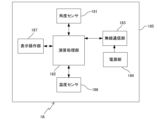
- FIG. 2 is a block diagram showing an example of the configuration of the sensor device in FIG. 1.
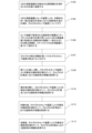
- FIG. It is a flowchart which shows the flow of the process of building an n-section column. It is a figure which shows the erection piece provided in each pillar, and the erection adjustment jig attached to an erection piece. It is a flowchart for explaining erection measurement of a steel frame. It is a conceptual diagram showing the flow of erection measurement of a steel frame.
- FIGS. 1 to 6 an embodiment of a measurement method that takes an architectural structure as a structure and uses its structural material as an object will be described based on FIGS. 1 to 6.
- a sensor device that measures structural materials of building structures is used.
- the measurement target of the sensor device the definition of the direction, etc.
- the measurement target (object) by the sensor device is a steel frame column 100p of one node configuring a multi-section steel frame building (see part (A) of FIG. 6, etc.)
- I will explain about it.
- steel-framed buildings the steel columns built on top of the foundation are called “1-node steel frames,” and the steel columns built on top of them are called “2-node steel frames,” and each time they go up, a number representing the node is used. (section number) increases.
- the vertical direction (gravity direction) is taken as the Z-axis direction
- the horizontal direction in the plane of the paper in FIG. 6(A) is referred to as
- the direction orthogonal to the axial direction, Z axis, and X axis is defined as the Y axis direction
- the directions of inclination (rotation) around the X axis, Y axis, and Z axis are defined as ⁇ x, ⁇ y, and ⁇ z directions, respectively.
- FIG. 1 schematically shows the overall configuration of a measurement system 10 used for erection measurement of steel structures.
- the plurality of sensor devices 18i are connected to the network 13 via a communication line, for example, a wireless LAN.
- three sensor devices 18 1 to 18 3 are representatively shown among the plurality of sensor devices 18 i .
- the plurality of three-dimensional surveying devices 30j are connected to the network 13 via a communication line, for example, a wireless LAN.
- two three-dimensional surveying instruments 30 1 and 30 2 are representatively shown among the plurality of three-dimensional surveying instruments 30 j .
- all of the communication lines may be wireless, but at least some of them may be wired.
- a configuration is adopted in which the outputs of the plurality of sensor devices 18 i and the outputs of the plurality of three-dimensional surveying instruments 30 j are provided to the server 12 via the communication line and the network 13.
- the network 13 and all of the communication lines that connect the server 12, the field-side computer 14, the mobile terminal 16, the plurality of sensor devices 18i , and the plurality of three-dimensional surveying devices 30j to the network 13 are described below.
- One network configured to include the network is referred to as a network 13 using the same reference numeral as the wide area network 13.
- a commonly used server computer is used as the server 12, but a cloud (computer) may also be used.
- the on-site computer 14 is a commonly used computer in this embodiment.
- the on-site computer 14 includes an operation section such as a keyboard and a mouse, and a screen such as a liquid crystal display.
- the on-site computer 14 performs data communication with the server 12 and the mobile terminal 16 via the network 13 in response to instructions input by the on-site supervisor or other administrator via the operation unit.
- the on-site computer 14 does not need to be provided and may be replaced by the mobile terminal 16.
- a manager (such as a site supervisor) uses the mobile terminal 16 to perform data communication with the server 12 and with other mobile terminals 16 carried by field workers via the network 13.
- the mobile terminal 16 is carried by a worker at a construction site.
- the mobile terminal 16 is, for example, a smartphone or a tablet PC.
- Measurement instructions and the like to the sensor device 18 i are given via the network 13 from either the mobile terminal 16 , the on-site computer 14 or the server 12 , and the output data from the sensor device 18 i is given via the network 13 to the server 12 . provided for. Further, necessary calculation processing using the output data from the sensor device 18i is performed by the server 12, and necessary information is sent from the server 12 to the mobile terminal 16 in response to an inquiry from the mobile terminal 16 or according to a predetermined program. is provided.
- the three-dimensional surveying instrument 30j for example, a type of total station that does not require a prism or other target and is capable of three-dimensional measurement is used.
- This three-dimensional surveying device 30j emits light to a target point (measurement position) and receives the reflected light (return light), thereby measuring the angle of inclination (vertical angle and horizontal angle) with one machine. Distances can be measured simultaneously.
- the three-dimensional surveying device may be a 3D laser scanner or the like, and any measuring device may be used regardless of the method as long as it can measure angle and distance information.
- the term "survey" used in this specification has a broad meaning and is synonymous with mere measurement.
- the three-dimensional surveying device described in this specification can also be referred to as a three-dimensional measuring device or a three-dimensional measuring device.
- Measurement instructions for the 3D surveying device 30j are given from either the mobile terminal 16, the site computer 14, or the server 12 via the network 13 , and the output data from the 3D surveying device 30j is sent via the network 13.
- the information is provided to the server 12 via the server 12.
- Necessary arithmetic processing using the output data from the three-dimensional surveying equipment 30j is performed by the server 12, and the necessary calculations are sent from the server 12 to the mobile terminal 16 in response to an inquiry from the mobile terminal 16 or according to a predetermined program. information will be provided.
- each of the sensor devices 18i includes an angle sensor 181, an arithmetic processing section 182, a wireless communication section 183, a power supply section 184 composed of, for example, a battery, a temperature sensor 186, a display operation section 187, and these. It has a waterproof casing 185 housed inside.
- the power supply unit 184 is configured to turn on and off the supply of power to each unit by remote control from the outside (for example, the server 12, the on-site computer 14, or the mobile terminal 16).
- the present invention is not limited to this, and the housing 185 may be provided with a power switch that can be turned on and off manually.
- a 3DMEMS (three-dimensional microelectromechanical system) tilt angle (tilt angle) sensor is used as an example.
- 3DMEMS tilt angle sensor is a precision tilt sensor created using 3DMEMS technology.
- the power requirements of 3DMEMS tilt angle sensors are extremely low, with power consumption in the microampere range, making them suitable for wireless applications.
- the angle sensor 181 includes two MEMS acceleration sensors with symmetrical output characteristics and a built-in ASIC. outputs information on the inclination angle ( ⁇ , ⁇ , ⁇ ) of the direction).
- the inclination angle is the inclination angle of the normal vector of the measurement surface at the measurement point. Therefore, the shift amount (lateral shift) of the measurement point can also be determined from the inclination angle by geometric calculation.
- the angle sensor is not limited to the 3DMEMS tilt angle sensor, but other types of three-dimensional tilt angle sensors may be used. Further, the angle sensor is not limited to a three-dimensional tilt angle sensor, but a two-dimensional tilt angle sensor or a one-dimensional tilt angle sensor may be used depending on the object to be measured. At this time, a two-dimensional tilt angle sensor and a one-dimensional tilt angle sensor may be combined, or a plurality of two-dimensional or one-dimensional tilt angle sensors may be used in combination.
- the arithmetic processing unit 182 is composed of, for example, a microcontroller unit (MCU), and includes a CPU (not shown), a memory device, an input/output circuit, and a timer circuit.
- the arithmetic processing unit 182 executes a processing algorithm defined by a program stored in the memory device.
- the arithmetic processing unit 182 controls the entire sensor device 18i .
- the ASIC built in the angle sensor 181 may also have the function of the arithmetic processing section 182.
- the wireless communication unit 183 functions as a Wi-Fi communication (wireless LAN communication) unit.
- the sensor device 18 i is capable of wireless LAN communication with the server 12 and other devices connected to the network 13 via the network 13 .
- a wired communication section may be provided in place of a part of the wireless communication section 183.
- a MEMS non-contact temperature sensor is used as an example.
- a MEMS non-contact temperature sensor measures the temperature of the surface of an object in a non-contact manner by receiving radiant heat energy from the object with a thermopile element.
- the power requirements of MEMS non-contact temperature sensors are extremely low, with power consumption in the microampere range.
- the temperature sensor is not limited to the MEMS non-contact temperature sensor, and other types of temperature sensors may be used.
- the display operation unit 187 is constituted by, for example, a so-called touch panel, and is capable of inputting and displaying data using a human finger or a touch pen.
- a plurality of recesses are formed in the bottom wall (back side wall) of the casing 185, and a permanent magnet is embedded in each recess. Therefore, the sensor device 18 i can be attached to an object such as a steel frame with one touch using the magnetic force of the permanent magnet. Furthermore, a plurality of open recesses are provided on the side surface of the bottom wall of the casing 185 for inserting a tool during removal. Therefore, the sensor device 18i can be removed from the object in a relatively short time. Note that a magnetic shielding member is disposed inside the housing 185 at a position close to the back surface to effectively prevent the magnetic force of the permanent magnet from affecting internal components.
- the method for fixing the sensor device to the object is not limited to magnetic force, and other fixing methods may be used.
- a mechanical fixing method or an adhesive method using adhesive or double-sided tape may be used.
- the object to which the sensor device is fixed is not limited to a steel frame (that is, the fixing method does not depend on the material of the object).
- the sensor device 18i configured as described above outputs measurement data (sensor data) such as inclination angle and temperature to the outside via the wireless communication section 183, but this sensor data includes the identification of the sensor device. It includes an ID which is information.
- the ID is linked to output information from the angle sensor 181 and the temperature sensor 186 by the arithmetic processing unit 182. Therefore, the server 12 or the like that receives sensor data via the network 13 can reliably identify which sensor device the sensor data is from.
- the sensor device 18i is not limited to the configuration of this embodiment, and the angle sensor 181, the wireless communication section 183, the temperature sensor 186, etc. do not all need to be configured integrally.
- the angle sensor 181 and/or temperature sensor 186 and other parts may be connected via a wireless or wired communication line, and data from the angle sensor 181 and/or temperature sensor 186 may be transmitted via the communication line. It may be configured to output power and supply power to the angle sensor 181 and/or the temperature sensor 186.
- FIG. 3 shows the process flow for constructing an n-section column.
- the prerequisite for starting the erection of the n-node pillar is that the erection of the (n-1) nodal pillar has been completed.
- step S2 the upper node column (in this case, the n node column) 100p is lifted by a crane and cut off to the ground.
- step S4 the installation adjustment jig is assembled to the column capital erection piece (or the column base erection piece of the upper column) of the lower column (here, (n-1) column) 100q .
- each column 100 (100 p or 100 q in FIG. 4) is made of a steel pipe (column steel frame) having a rectangular cross-sectional shape, and the column base and column capital of the column steel frame are An erection piece 40 is provided protruding from each.
- the erection pieces 40 are welded to four mutually perpendicular surfaces of a column steel frame having a rectangular cross-sectional shape. Each erection piece 40 is perpendicular to each surface of the column 100 and extends in the vertical direction.
- Four erection adjustment jigs 50 are respectively assembled to the four-sided erection piece 40 of the lower joint column 100q .
- the installation adjustment jig 50 used in this embodiment is used to assemble to the joint portion of a column, prevent the column from falling, adjust the misalignment, adjust the fall, etc.
- a detailed configuration of a steel frame column inclination adjustment device having a configuration similar to that of the erection adjustment jig 50 is disclosed in, for example, Japanese Patent Laid-Open No. 2001-355340.
- the erection adjustment jig 50 includes a main body frame 50A, which is a connecting body that connects an erection piece 40 of the column base of the upper column 100p and an erection piece 40 of the column capital of the lower column 100q , and a main body frame 50A. It is equipped with a plurality of bolts (specifically, a fall prevention bolt, a misalignment adjustment bolt, a tilt adjustment bolt, etc.) to realize the various adjustment functions mentioned above.
- a plurality of bolts specifically, a fall prevention bolt, a misalignment adjustment bolt, a tilt adjustment bolt, etc.
- the upper node column 100p is lifted by a crane and temporarily fixed to the lower node column 100q using the erection adjustment jig 50. Specifically, the upper nodal column 100p is suspended, and the four erection adjustment fixtures attached to the erection piece 40 of the capital of the lower nodal column 100q (or the erection piece 40 of the column base of the upper nodal column 100p ) are suspended. With the tool 50 open (see FIG. 4), place the upper nodal column 100p on the lower nodal column 100q , and place the erection piece 40 on the base of the upper nodal column 100p (or the capital of the lower nodal column 100q ).
- misalignment refers to a positional misalignment in the horizontal plane between the capital of the lower nodal column 100q and the base of the upper nodal column 100p.Adjustment for this misalignment is carried out by suspending the upper nodal column 100p with a crane. With the upper joint pillar 100p placed on the lower joint pillar 100q , use the four erection adjustment jigs 50 so that the upper joint pillar 100p and the lower joint pillar 100q appear to be one pillar. This is done by adjusting the position of the upper nodal column in the X-axis direction and Y-axis direction using . After this, the crane is released (step S10). Note that if the weight of the pillar is lighter than a predetermined value, it is also possible to release the crane before performing the misalignment adjustment.
- column inclination adjustment (also called rebuilding) is performed.
- This inclination adjustment is performed using four erection adjustment jigs 50 while measuring information on the inclination angle of the upper joint column so that the inclination error with respect to the vertical axis (Z axis) is within a predetermined tolerance. This is done by adjusting the inclination angle of the upper nodal column.
- erected means the degree of verticality of the pillar.
- the four erection adjustment jigs 50 are used to fix the upper joint pillar and the lower joint pillar.
- This fixing is performed by temporarily tightening (lightly tightening) each adjustment bolt of the four erection adjustment jigs 50 using a special tool.
- the processes from steps S2 to S14 described above are performed sequentially (or partially in parallel) for a plurality of upper node columns (n node columns).
- a steel beam for a beam (steel beam) includes a pair of beam end members 100a (see FIG. 6(A)) located at both ends of the steel beam and joined to the column 100, and a pair of beam end members 100a (see FIG. 6(A)).
- beam insertion means arranging a central member between two beam end members respectively joined to two columns, and connecting the central member and each of the beam end members on both sides with a beam joint. It means to do.
- the inclination angle of the columns changes from before the beam is inserted due to the horizontal force that acts on the columns connected to both ends of the steel beam. Sometimes. In order to confirm this change, it is necessary to re-measure the information on the inclination angle after beam insertion.
- Readjustment after beam insertion is performed as necessary based on the remeasurement results.
- Readjustments after beam installation may include adjusting the misalignment of columns, adjusting column inclination, and adjusting column levels. These are performed by readjusting the four erection adjustment jigs 50. However, when re-adjusting the construction adjustment jig, if the misalignment of the pillars cannot be adjusted sufficiently, a different adjustment jig may be used. Further, for example, in readjusting the inclination of a column, the inclination angle of the column is adjusted while measuring information on the inclination angle of the column, and it is confirmed that the inclination error is within a predetermined tolerance.
- the beam joints and column joints are fully tightened.
- the final tightening of the beam joint is performed by tightening the high-strength bolts at the joint between the column and the beam, and the final tightening of the column joint is performed by final tightening each adjustment bolt of the four erection adjustment jigs 50. It will be done.
- the information on the inclination angle of the upper joint pillar 100p is measured (hereinafter also referred to as inclination angle measurement) to confirm that the inclination error is within a predetermined tolerance. .
- the inclination error of the column is normally within the allowable value. If the inclination error of the column is not within the allowable value, the inclination angle of the column is adjusted once again, and then it is confirmed that the inclination error is within the allowable value.
- the control tolerance for column collapse is set at 1/1000 of the column length and 10 mm or less, so the tolerance value can be set to satisfy this and has a certain width.
- the upper joint pillar 100p is welded to the lower joint pillar 100q , and then the four erection adjustment jigs are removed (step S22). After that, the erection piece will be cut. Even after welding, the inclination angle of the upper node column 100p is measured for the purpose of confirming that the angle of inclination of the upper node column is within the permissible value.
- the inclination error of the column is normally within the allowable value.
- the inclination error of the upper joint column 100p is not within the allowable value.
- the measurement results of the inclination angle can be used. For example, based on the measurement result of the inclination angle, an offset is set to the target value of the column head of the upper node column (here, the (n+1) node column) to cancel (the influence of) the inclination error. Is possible.
- the inclination angle of the upper joint column may be measured immediately before welding to check whether the inclination error is within the allowable value, and if it is outside the allowable value, the welding may be performed after readjusting.
- the sensor device 18i is used to measure the inclination angle of the upper joint column in each of the above-mentioned steps S12, S16, and S20, and to confirm the inclination angle of the upper joint column after welding (step S22). It will be done.
- FIG. 5 shows a flowchart for measuring the erection of a steel frame.
- FIGS. 6(A) to 6(C) show conceptual diagrams showing the flow of steel frame erection measurement.
- an n-node column (hereinafter referred to as a target column) 100 p to be measured is shown together with a lower nodal column 100 q .
- the target pillar 100p is preliminarily fixed (immediately after temporarily fixing the target pillar in step S6 or before cutting the target pillar) at a predetermined number of places (for example, three places on each of the +X side surface and the ⁇ Y side surface,
- the sensor devices 18 1 to 18 6 are attached to the respective attachment positions (six in total).
- a mark is attached to the mounting position in advance, and the position of the mark is set in advance so that it matches the measured position of the target pillar managed by the server 12 after the target pillar is erected.
- the sensor device 18 1 and the sensor device 18 4 , the sensor device 18 2 and the sensor device 18 5 , and the sensor device 18 3 and the sensor device 18 6 are installed at the same height.
- the sensor device 18i may be attached only to at least two arbitrary attachment positions (positions of marks) as long as the sensor apparatus 18i includes two attachment positions on the column head. Alternatively, the marks may be provided at seven or more positions.
- step S102 the three-dimensional surveying instrument 30j is installed at a position where positional information (in this case, inclination angle information) of the target pillar 100p can be measured.
- FIG. 6(A) shows the state after the three-dimensional surveying instrument 301 is installed.
- Parallel measurements by the sensor device 18 i and the three-dimensional surveying instrument 30 j may be performed at least partially in parallel.
- the measurements of inclination angles at measurement points at the same height position of the target column 100 by the three-dimensional surveying instrument 30j and the sensor device 18i in step S104 are not necessarily performed at least partially in parallel in time. You don't have to do it. That is, after measurement by one of the three-dimensional surveying instrument 30 j and the sensor device 18 i , a short time interval during which the measured value hardly changes may be performed, and then measurement by the other one may be performed.
- step S106 based on the measurement result in step S104, information on the inclination angle acquired by the sensor device 18i is converted into information on the inclination angle acquired by the three-dimensional surveying instrument 30j used in the parallel measurement in step S104. Find (calculate) calibration information to match the information.
- the calibration information ( ⁇ y, ⁇ z) in the ⁇ y direction and the ⁇ z direction is obtained.
- Step S106 Calculation of the calibration information in step S106 is performed for each sensor device 18i based on the inclination angle acquired by the three-dimensional surveying instrument 30j used in parallel measurement.
- the calibration information in the ⁇ z direction is based on the inclination angle in the ⁇ z direction acquired by the three-dimensional surveying instrument 302 and the inclination angle in the ⁇ z direction acquired by the sensor device 18 6 (18 5 , 18 4 ). You can ask for it. That is, it is sufficient to obtain the calibration information in the ⁇ z direction only for one of the sensor devices attached to the same height position on the column.
- the inclination angle in the ⁇ x direction for the sensor device 18 3 (18 2 , 18 1 ) is not taken up because the sensor device 18 6 (18 5 , 18 4 ) is provided at the same height position. It is. Therefore, when only the three sensor devices 18 3 , 18 2 , and 18 1 are attached to a pillar, in parallel with the measurement of the inclination angle of the -Y side surface of the pillar by the three-dimensional surveying device 30 2 .
- the sensor device 18 3 (18 2 , 18 1 ) may measure the inclination angle of the pillar in the ⁇ x direction.
- the calibration information ⁇ x for the sensor device 18 3 (18 2 , 18 1 ) is obtained using the inclination angle ⁇ 1 at the measurement point at the same height position by the 3D surveying instrument 30 2 . good. In this way, it is sufficient to prepare three sensor devices for each target column.
- Step S107 origin reset is performed to reset the measurement origin of each sensor device 18 i so that it matches the measurement origin of the three-dimensional surveying instrument 30 j used in the parallel measurement.
- the calibration information is a simple offset, but the present invention is not limited to this, and the calibration information may be managed as a correction coefficient.
- the three-dimensional surveying equipment 30 used in the parallel measurement can use the calibration information to update information on the inclination angle at each measurement point measured by each sensor device 18i each time a measurement is performed without resetting the origin.
- the information may be converted into information on the inclination angle obtained at j .
- "parallel" is not limited to cases in which two types of operations (for example, measurement operations) are performed at approximately the same time, but also refers to cases in which two types of operations (for example, measurement operations) are performed with at least a partial time lag, as well as cases in which two types of operations are performed consecutively. This includes the case where the end point of one action almost coincides with the start point of the other action.
- the sensor device 18i measures the inclination angle at the measurement point of the target pillar 100p , so that the angle of inclination of the target pillar 100p measured using the three-dimensional surveying instrument 30j is corrected.
- Information on the tilt angle that is substantially equal to the information on the tilt angle at the measurement point can be obtained.
- each three-dimensional surveying instrument 30j can be used for another measurement task.
- each sensor device 18i measures the inclination angle of the target pillar 100p , obtains sensor data output from each sensor device 18i , and measures the inclination angle at each measurement point. Get slope information.
- the re-erection is performed by adjusting the re-erecting adjustment jig 50 based on the information on the inclination angle obtained through measurement by the sensor device 18i in step S12 described above.
- each sensor device 18i measures the inclination angle of the target column 100p , obtains sensor data output from each sensor device 18i , and calculates the inclination angle at each measurement point. Get corner information.
- each sensor device 18i measures the inclination angle of the target column 100p , obtains sensor data output from each sensor device 18i , and calculates the inclination angle at each measurement point. Get corner information.
- FIG. 6(B) shows a state in which the inclination angle of the target column 100p is measured by each sensor device 18i after the final tightening.
- step S114 the inclination angle of the target column 100p is measured by each sensor device 18i , and the inclination angle of the target column 100p is measured by each sensor device 18i .
- sensor data is acquired, and information on the inclination angle at each measurement point is acquired.
- FIG. 6C shows a state in which the inclination angle of the target column 100p is measured by each sensor device 18i after welding.
- step S114 if the measurement result in step S114 (or the inclination error obtained based on it) is not within the allowable value due to some factor, readjustment is no longer possible as described above.
- the sensor device 18 i when the sensor device 18 i is used to measure the upper node column of the target column 100 p , it is necessary to remove the sensor device 18 i from the target column 100 p before stacking the upper node column on the target column 100 p .
- the position, displacement, etc. of the column head of the target column 100p cannot be measured in real time.
- the sensor device 18i if the sensor device 18i is removed from the target column 100p immediately before starting measurement of the upper node column, the inclination angle at the measurement point of each sensor device immediately before removal will be By using the information, it is possible to set the offset of the target position of the capital of the upper column column in the same manner as in the case of real-time measurement described above.
- the above-mentioned immediately preceding measurement information cannot be obtained. For this reason, if the sensor device 18 i is removed from the target pillar 100 p early, the above offset cannot be set using the measurement information of the sensor device 18 i directly.
- the relationship between the measured value of the inclination angle at the measurement point measured by the sensor device 18 i and the temperature (t) is converted into a function, in other words, the measured value is expressed as a function f(t) of temperature. And so. Then, the measurement information of the sensor device 18 i is calculated using the function f(t). Specifically, it is as follows.
- the measurement data of the inclination angle at each measurement point of the target column 100p and the measurement data of the temperature at the time of the measurement are collected for a predetermined period of time (for example, 24 hours) before removing the sensor device 18i . time) at predetermined sampling intervals, and a plurality of sampled data were plotted on a two-dimensional coordinate system with temperature as the horizontal axis and tilt angle as the vertical axis. Then, a function f(t) whose parameter is the temperature t obtained by function fitting the plotted points is obtained for each (measurement point of) the sensor device.
- the reference temperature T for example, the average value of the temperatures (average temperature) over the above-mentioned predetermined time period is also determined.
- the above-mentioned offset is actually taken into consideration when adjusting the inclination in the construction of the upper joint pillar ((n+1) joint pillar).
- the inclination angle and temperature are measured in parallel by the sensor device 18 i , but the inclination angle of the target column 100 p is measured by the sensor device 18 i using a temperature sensor different from the sensor device. Temperature measurement may be performed in parallel.
- the inclination angle of a steel column is also related to other physical quantities other than temperature, such as "wind force (k),""load from above (w),” and “ground vibration (g).” I know.
- a function that has temperature (t) and at least one of the following parameters: wind force (k), load from above (w), and ground vibration (g) instead of f(t).
- a function whose parameters include temperature (t), wind force (k), load from above (w), and ground vibration (g) can be expressed as f(t, k, w, g).
- a function in such a format may be obtained by simulation or the like.
- the steel frame with n ( ⁇ 2) nodes (n node column) is the target column 100 p , but the 1 node column is the target column, and the sensor device 18 Measurements such as the inclination angle and temperature may be performed on the nodal column) in the same manner as for the target column 100p described above.
- the sensor device 18 Measurements such as the inclination angle and temperature may be performed on the nodal column) in the same manner as for the target column 100p described above.
- the processing (including calculation) of the output data of the sensor device 18 i and the three-dimensional surveying device 30 j related to the measurements described so far is performed by the server 12, and is necessary for adjusting the construction adjustment jig 50.
- Such information is provided from the server 12 to the mobile terminal 16 carried by the field worker in response to the inquiry.
- the measurement system 10 constitutes a steel frame erection adjustment system based on the measurement results of the steel frame inclination angle, which includes a part of the adjustment work of the erection adjustment jig by site workers. You can also think that.
- at least part of the functions of the server 12 may be provided in the on-site computer 14.
- the three-dimensional surveying instrument 30j substantially the same measurement data as the measurement of the inclination angle at a predetermined measurement point of the target column can be obtained.
- the sensor device 18i measures the inclination angle at a predetermined measurement point of the target column.
- This measurement data of the inclination angle hardly includes measurement errors caused by repeated measurements a plurality of times. The reason for this is that since the sensor device remains fixed at a predetermined mounting position on the pillar, measurement errors due to positional deviation of the sensor device will not occur even if measurements are repeated.
- the sensor device since the sensor device always measures the amount of variation in the inclination angle from the reference time at any time, if the time of parallel measurement with the three-dimensional surveying instrument 30j mentioned above is taken as the reference time, then the reference.
- the reference By using the above-mentioned calibration information calculated using the measurement results of the sensor device and 3D surveying equipment at the time, it is possible to measure the erection of each steel column using surveying equipment such as a total station. It becomes possible to obtain substantially equivalent building measurement results.
- the sensor device uses measurement data measured in real time at the time of erecting the upper joint column, immediately before the upper joint column is erected, or at a predetermined time after welding.
- Various offset setting methods have been adopted that use measurement data measured across the area. Therefore, compared to conventional offsets, the offsets set using these setting methods are based on information that more accurately reflects the actual positional shift of the column head of the lower column at the time of erection of the upper column. I can say that there is. This is because conventionally, the offset of the installation position of the upper joint pillar was set by relying on the measurement result of the inclination angle of the lower joint pillar, which was measured only once after welding using a surveying device such as a total station.
- the construction of a steel frame structure which is a type of building structure, is taken up, and a measurement system having a plurality of sensor devices 18 i and a plurality of three-dimensional surveying instruments 30 j is described.
- the case where the measurement method according to the present invention is applied to construction measurement using No. 10 has been explained.
- the measurement method according to the above embodiment can be implemented not only in the construction of a steel frame structure, but also in structural materials of a building structure (structure) under construction (construction).
- the object may be a ceiling, a roof, etc.
- the structures targeted by the measurement method according to the present invention are not limited to buildings, but may also be elevated structures, bridges, dams, tunnels, stadiums, halls, etc. In short, structures in which three-dimensional surveying equipment is used for construction (construction) It can be applied to everything.
- the target object is not limited to a structure, but may also be an earth retaining wall, a slope, etc.
- the measurement method according to the above embodiment can be carried out using a part of the building material (structural material) such as a pillar, wall, ceiling, or roof as an object. Can be done.
- the object is not limited to a building, but may be a part of a structure such as an elevated bridge, a dam, a tunnel, a stadium, or a hall, or may be an earth retaining wall, a slope, or the like.
- information on the inclination angle at the measurement point of the column as a structural material measured by the three-dimensional surveying device 30j (first position information), and information on the measurement point of the column measured by the sensor device 18i .
- first position information information on the inclination angle at the measurement point of the column as a structural material measured by the three-dimensional surveying device 30j
- second position information information on the measurement point of the column measured by the sensor device 18i .
- the calibration information of the measurement information of the device 18 i is not limited to calibration information that makes the second position information match the first position information.
- the calibration information may be information that indicates a certain relationship between the position information measured by the sensor device and the position information measured by the 3D surveying equipment, and the calibration information It may also be a coefficient representing the relationship between the first position information and the second position information measured by the sensor device.
- the sensor device 18 i and the three-dimensional surveying device 30 j measure the inclination angle at the measurement point at the same height position of the target column 100.
- the measurement points of the sensor device 18i and the three-dimensional surveying instrument 30j do not necessarily have to be the same.
- the sensor device 18 i and the three-dimensional surveying device 30 j which have different measurement points, respectively measure position information (inclination angle information) at multiple points of the target column 100, and from the measurement results, the target column ( An approximate curve representing the inclination of the steel frame) may be calculated, and calibration information of the measurement information of the sensor device regarding the height direction of the steel frame may be obtained from the calculated approximate curve.
- the three-dimensional surveying equipment 30j is used to obtain position information (inclination angle information).
- a plurality of sensors are calibrated in advance to collect position information (information on inclination angle) at multiple points at different positions in the height direction on the measurement surface of the target column 100 so that the measured values agree with each other.
- Each measurement is performed using the device 18i .
- the information on the inclination angle at each of the plurality of points measured using the three-dimensional surveying device 30j is fitted with a function to create an approximate curve indicating the inclination of each point in the height direction on the measurement surface of the target column 100.
- a polynomial function f 1 (z) representing the height z as a parameter is calculated.
- the information on the inclination angle at each of the plurality of points measured by the plurality of sensor devices 18i is fitted with a function to create an approximate curve indicating the inclination of each point in the height direction on the measurement surface of the target column 100.
- a polynomial function f 2 (z) with the height z as a parameter is calculated.
- the measurement information of the sensor device 18 i whose measurement points are each point in the height direction on the measurement surface of the target column 100 is It is also possible to acquire calibration information that approximates the measurement information at a point at the same height position on a predetermined surface of the target column 100 by the three-dimensional surveying device 30j .
- the calibration information that makes the measurement information of any sensor device 18 i substantially match the measurement information of the three-dimensional surveying instrument 30 j is such that the value of the height z of the measurement point of the sensor device 18 i is calculated using a polynomial function.
- the premise of calculating the polynomial function f 2 (z) is to measure the height on the measurement surface of the target column 100 using a plurality of sensor devices 18 i that have been calibrated in advance so that the measured values match.
- position information (inclination angle information) is to be measured at each of a plurality of points having different positions in the direction
- a single sensor device 18i is moved to measure the position information in the height direction on a predetermined surface of the target column 100.
- Position information (inclination angle information) may be measured at each of a plurality of points at different positions.
- the calibration information may be information including a function.
- the sensor devices 18 i are arranged along the vertical direction on the measurement surface, but it is also possible to arrange the sensor devices 18 i two-dimensionally on the measurement surface.
- the sensor devices may be two-dimensionally arranged on the measurement surface.
- the sensor device 18i outputs the inclination angle of the normal vector of the measurement surface (three-dimensional inclination angle), so the measurement surface of the object can be determined from the measurement point coordinates and the measured value of the normal vector. It is also possible to derive the shape (surface shape).
- the shape may be calculated by determining the height (shift amount, lateral deviation amount) of each measurement point relative to the reference plane using the surface slope of each measurement point and its first-order integral, or
- the shape of the object may be determined based on a function obtained by changing the function fitted to slope distribution data obtained from a plurality of pieces of data about the object into an integral system.
- a function such as differential Zernike can be used, for example.
- an approximated surface expressed by Fourier series expansion is created so that the error at each measurement point is minimized.
- the shape may be calculated by optimizing the order and coefficients.
- the shape can be calculated using inclination angles at a plurality of measurement points, it is possible to use various methods using various functions.
- determining the shape of a measurement surface using the three-dimensional surveying device 30j as in the case of the sensor device 18i , by arranging a plurality of measurement points two-dimensionally on the measurement surface, the position obtained at each measurement point can be Using the information, the shape of the measurement surface can be similarly determined.
- the information calculated from the position information measured by the sensor device is not limited to the inclination of the column (one-dimensional inclination information), but may be two-dimensional information such as the surface shape. Note that in the above embodiment.
- the measurement information of the 3D surveying equipment and the sensor device is associated with the angle of inclination, but the amount of lateral deviation (shift amount) is calculated from the angle of inclination obtained for each measurement point, and the amount of shift is used to calculate the calibration information. Good to calculate and manage.
- the server 12 that constitutes the measurement system 10 may be under the control of a user of the sensor device, such as a construction company. Alternatively, if the sensor device is leased (or rented) from a supply company (manufacturer, supplier, etc.) to a construction company, the server 12 may be under the control of the supply company.
- 18 i (18 1 , 18 2 , 18 3 , 18 4 , 18 5 , 18 6 )...sensor device, 30 j (30 1 , 30 2 )... three-dimensional surveying equipment, 100 p ... pillar.
Landscapes
- Engineering & Computer Science (AREA)
- Physics & Mathematics (AREA)
- General Physics & Mathematics (AREA)
- Architecture (AREA)
- Radar, Positioning & Navigation (AREA)
- Remote Sensing (AREA)
- Spectroscopy & Molecular Physics (AREA)
- Manufacturing & Machinery (AREA)
- Mechanical Engineering (AREA)
- Civil Engineering (AREA)
- Structural Engineering (AREA)
- Electromagnetism (AREA)
- Conveying And Assembling Of Building Elements In Situ (AREA)
- Length Measuring Devices With Unspecified Measuring Means (AREA)
Abstract
Description
本願は、2022年7月8日に出願された特願2022-110227号に基づき優先権を主張し、その内容をここに援用する。
このように、従来のトータルステーションなどの測量機器を用いる構造材の計測方法には、明らかに改善の余地がある。
サーバ12としては、本実施形態では、一般に使用されるサーバ用のコンピュータが用いられているが、クラウド(コンピュータ)を用いても良い。
表示操作部187は、例えば、いわゆるタッチパネルによって構成され、人の指、あるいはタッチペンによるデータの入力及び表示などが可能になっている。
次のステップS4では、下節柱(ここでは(n-1)節柱)100qの柱頭エレクションピース(又は上節柱の柱脚エレクションピース)に建て入れ調整治具を組み付ける。一例として図4に示されるように、各柱100(図4では100p又は100q)はそれぞれ矩形の横断面形状を有する鋼管(柱用鉄骨)から成り、その柱用鉄骨の柱脚と柱頭にそれぞれエレクションピース40が突設されている。エレクションピース40は、矩形の横断面形状を有する柱用鉄骨の互いに直交する4面にそれぞれ溶接されている。各エレクションピース40は柱100の各面と直交し、上下方向へ伸びている。下節柱100qの4面のエレクションピース40に4つの建て入れ調整治具50がそれぞれ組付けられる。本実施形態で用いられる建て入れ調整治具50は、柱のジョイント部に組付け、柱の転倒防止、目違い調整、倒れ調整等を行うためのものである。建て入れ調整治具50と同様の構成を有する鉄骨柱傾き調整装置の詳細な構成が、例えば特開2001-355340号公報に開示されている。
この後、クレーンが解放される(ステップS10)。なお、柱の重量が所定値より軽い場合には、目違い調整の実施前にクレーンを開放することも可能である。
次のステップS14では、4つの建て入れ調整治具50で、上節柱と下節柱を固定する。この固定は、4つの建て入れ調整治具50が備える各調整ボルトを専用の工具を用いて仮締めする(軽く締める)ことで行われる。
上記のステップS2~S14までの処理は、複数の上節柱(n節柱)について順次(又は一部並行して)行われる。
まず、ステップS102において、3次元測量機器30jを、対象柱100pの位置情報(この場合、傾斜角の情報)の計測が可能となる位置に設置する。図6(A)には、3次元測量機器301が設置された後の状態が示されている。
δθz=γ2-γ1
また、例えば、3次元測量機器302で取得されたθx方向の傾斜角α1とセンサ装置186(185、184)で取得されたθx方向の傾斜角α2とに基づいて、θx方向の較正情報δθxを求める。
δθx=α2-α1
ただし、θz方向の較正情報は、3次元測量機器302で取得されたθz方向の傾斜角とセンサ装置186(185、184)で取得されたθz方向の傾斜角とに基づいて、求めても良い。すなわち、θz方向の較正情報は、柱の同一の高さ位置に取り付けられるセンサ装置の一方についてのみ求めれば足りる。
較正情報の算出後、それぞれの3次元測量機器30jは別の計測作業に用いることが可能になる。
なお、鉄骨柱の傾斜角等は、温度以外の他の物理量、例えば、「風力(k)」、「上部からの荷重(w)」、「地面振動(g)」などとも関連性があることがわかっている。
この場合には、必要に応じ、2節柱の柱頭の建て込み目標位置に対するオフセットを、1節柱に対するセンサ装置の計測データを用いて、前述と同様にして設定することが可能である。
また、完成した建築構造物(構造物)においても、その一部、例えば柱、壁、天井、屋根などの建造材(構造材)を対象物として、上記実施形態に係る計測方法を実施することができる。この場合も、ビルに限られず、高架、橋梁、ダム、トンネル、スタジアム、ホールなどの構造物の一部を対象物としても良いし、土留壁、法面などを対象物としても良い。
なお、上記の較正情報の取得に関する、多項式関数を用いた説明から明らかなように、較正情報を、関数を含む情報としても良い。
なお、上記実施形態では。3次元測量機器とセンサ装置の計測情報の対応づけを傾斜角で行うものとしたが、計測点ごとに得られる傾斜角から横ずれ量(シフト量)を求め、このシフト量を使って較正情報を算出、管理して良い。
Claims (21)
- 構造物の構造材を対象物とする計測方法であって、
3次元測量機器と前記構造材に取り付けられたセンサ装置でそれぞれ前記構造材の位置情報を計測することと、
前記3次元測量機器と前記センサ装置との両方の位置情報の計測結果に基づいて、前記センサ装置の計測情報を較正する較正情報を取得することと、を含む計測方法。 - 請求項1に記載の計測方法において、
前記較正情報の取得後、前記センサ装置によって計測される情報と前記較正情報とを使って前記構造材の位置情報の計測を行うことをさらに含む計測方法。 - 請求項2に記載の計測方法において、
複数点で前記位置情報の計測を行い、その計測結果を用いて前記構造材の形状情報を求める計測方法。 - 請求項3に記載の計測方法において、
前記位置情報の計測に用いられる前記センサ装置は、角度情報を計測するセンサを含む計測方法。 - 請求項4に記載の計測方法において、
前記センサは、前記角度情報として重力方向を基準とする角度を計測する計測方法。 - 請求項4又は5に記載の計測方法において、
前記角度情報から前記センサ装置の計測点の横ずれを求め、求めた横ずれを用いて前記構造材の前記形状情報を取得する計測方法。 - 請求項1に記載の計測方法において、
前記計測することでは、前記3次元測量機器と前記センサ装置でそれぞれ前記構造材の複数点での位置情報を計測し、
前記取得することでは、前記3次元測量機器と前記センサ装置でそれぞれ計測された前記構造材の複数点での位置情報に基づいて、前記較正情報を取得する計測方法。 - 請求項1に記載の計測方法において、
前記計測することでは、前記3次元測量機器及び前記センサ装置でそれぞれ前記構造材に設定された計測点での位置情報を計測し、
前記取得することでは、前記3次元測量機器と前記センサ装置でそれぞれ計測された前記計測点での位置情報に基づいて前記較正情報を取得する計測方法。 - 請求項7又は8に記載の計測方法において、
前記較正情報の取得後には、前記センサ装置によって前記構造材の位置情報が計測され、その計測結果として、計測された位置情報が前記較正情報で実質的に較正された位置情報が用いられる計測方法。 - 請求項1~9のいずれか一項に記載の計測方法において、
前記センサ装置で計測される前記位置情報は、前記構造材の重力方向を基準とする傾斜角の情報を含む計測方法。 - 請求項1~10のいずれか一項に記載の計測方法において、
完成した構造物の構造材を前記対象物とする計測方法。 - 請求項1~10のいずれか一項に記載の計測方法において、
建造中の構造物の構造材を前記対象物とする計測方法。 - 請求項12に記載の計測方法を利用する構造物の建造方法であって、
建て込まれる柱を前記対象物として所定の計測点における傾斜角の情報を、前記センサ装置と前記3次元測量機器とで計測し、該計測結果に基づいて、前記センサ装置で計測される傾斜角の情報を前記3次元測量機器で計測される傾斜角の情報に一致させるための前記較正情報の取得が行われる構造物の建造方法。 - 請求項13に記載の構造物の建造方法において、
前記センサ装置と前記3次元測量機器とによる前記傾斜角の情報の計測は、並行して行われる構造物の建造方法。 - 請求項13又は14に記載の構造物の建造方法において、
前記較正情報の取得後、該較正情報を用いて前記センサ装置の計測原点を前記3次元測量機器の計測原点に一致させる前記センサ装置の原点リセットを行うことをさらに含み、
前記原点リセット後、前記柱の傾斜角は、前記原点リセット後の前記センサ装置で計測される構造物の建造方法。 - 請求項13~15のいずれか一項に記載の構造物の建造方法において、
前記建て込まれる前記柱は、2節以降の任意の節の柱であり、
前記較正情報の取得のための前記センサ装置と前記3次元測量機器とによる前記傾斜角の情報の計測は、前記任意の節の柱について目違い調整及び倒れ調整を含む位置調整時における任意のタイミングで行われる構造物の建造方法。 - 請求項16に記載の構造物の建造方法において、
前記構造物は、構造材として鉄骨を用いる鉄骨造である構造物の建造方法。 - 請求項17に記載の構造物の建造方法において、
前記較正情報の取得後、梁入れ後の再計測の際、柱継手の本締めの後、及び柱の溶接後の少なくとも1つのときに、前記センサ装置により前記任意の節の柱を対象物として傾斜角の情報の計測が行われる構造物の建造方法。 - 複数節の柱を含む構造物の建造方法であって、
建て込まれた計測対象の柱の上節の柱の建て込み時又は建て込み直前に前記計測対象の柱に取り付けられたセンサ装置により計測した前記計測対象の柱の計測点における傾斜角の情報に基づいて、前記上節の柱の柱頭の建て込み目標値にオフセットを設定することを含む構造物の建造方法。 - 複数節の柱を含む構造物の建造方法であって、
センサ装置が取り付けられた計測対象の柱の溶接の終了後、計測対象の柱の上節の柱の建て込みに先立って、前記計測対象の柱の傾斜角の情報を前記センサ装置で所定時間にわたり所定のサンプリング間隔で計測するのと並行して温度tを計測することと、
計測により取得したサンプリングデータに基づいて、前記温度tをパラメータとして含む前記センサ装置で取得される前記傾斜角の情報を表す関数fを求めることと、
基準温度Tを前記パラメータtに代入した前記関数fに基づいて、前記上節の柱の柱頭の建て込み目標値にオフセットを設定する構造物の建造方法。 - 請求項20に記載の構造物の建造方法において、
前記センサ装置は、温度センサを有し、
前記温度tの計測は、前記温度センサを用いて行われる構造物の建造方法。
Priority Applications (3)
| Application Number | Priority Date | Filing Date | Title |
|---|---|---|---|
| JP2024532603A JPWO2024010024A1 (ja) | 2022-07-08 | 2023-07-05 | |
| US18/867,851 US20250321099A1 (en) | 2022-07-08 | 2023-07-05 | Measurement method and method for constructing structure |
| JP2026009573A JP2026090289A (ja) | 2022-07-08 | 2026-01-23 | 位置情報の推定方法及びシステム |
Applications Claiming Priority (2)
| Application Number | Priority Date | Filing Date | Title |
|---|---|---|---|
| JP2022-110227 | 2022-07-08 | ||
| JP2022110227 | 2022-07-08 |
Publications (1)
| Publication Number | Publication Date |
|---|---|
| WO2024010024A1 true WO2024010024A1 (ja) | 2024-01-11 |
Family
ID=89453422
Family Applications (1)
| Application Number | Title | Priority Date | Filing Date |
|---|---|---|---|
| PCT/JP2023/024880 Ceased WO2024010024A1 (ja) | 2022-07-08 | 2023-07-05 | 計測方法及び構造物の建造方法 |
Country Status (3)
| Country | Link |
|---|---|
| US (1) | US20250321099A1 (ja) |
| JP (2) | JPWO2024010024A1 (ja) |
| WO (1) | WO2024010024A1 (ja) |
Cited By (1)
| Publication number | Priority date | Publication date | Assignee | Title |
|---|---|---|---|---|
| WO2026042264A1 (ja) * | 2024-08-23 | 2026-02-26 | 株式会社ニコン | 位置情報取得方法及びシステム、並びに構造物の建築方法及びシステム |
Citations (4)
| Publication number | Priority date | Publication date | Assignee | Title |
|---|---|---|---|---|
| JPS59102061A (ja) * | 1982-11-30 | 1984-06-12 | 大成建設株式会社 | 柱建込み方法及びその柱の建入れ直し装置 |
| JPH06101349A (ja) * | 1992-09-16 | 1994-04-12 | Kajima Corp | 鉄骨建て入れ修正方法 |
| JP2017181340A (ja) * | 2016-03-31 | 2017-10-05 | 日立建機株式会社 | 建設機械及び建設機械の較正方法 |
| JP2018146408A (ja) * | 2017-03-06 | 2018-09-20 | 株式会社トプコン | 建築作業機械における傾斜センサー補正量取得方法 |
Family Cites Families (1)
| Publication number | Priority date | Publication date | Assignee | Title |
|---|---|---|---|---|
| JP2007064853A (ja) * | 2005-08-31 | 2007-03-15 | Hitachi Ltd | 複合測位による移動体の測位制御装置、システムおよびプログラム |
-
2023
- 2023-07-05 JP JP2024532603A patent/JPWO2024010024A1/ja active Pending
- 2023-07-05 US US18/867,851 patent/US20250321099A1/en active Pending
- 2023-07-05 WO PCT/JP2023/024880 patent/WO2024010024A1/ja not_active Ceased
-
2026
- 2026-01-23 JP JP2026009573A patent/JP2026090289A/ja active Pending
Patent Citations (4)
| Publication number | Priority date | Publication date | Assignee | Title |
|---|---|---|---|---|
| JPS59102061A (ja) * | 1982-11-30 | 1984-06-12 | 大成建設株式会社 | 柱建込み方法及びその柱の建入れ直し装置 |
| JPH06101349A (ja) * | 1992-09-16 | 1994-04-12 | Kajima Corp | 鉄骨建て入れ修正方法 |
| JP2017181340A (ja) * | 2016-03-31 | 2017-10-05 | 日立建機株式会社 | 建設機械及び建設機械の較正方法 |
| JP2018146408A (ja) * | 2017-03-06 | 2018-09-20 | 株式会社トプコン | 建築作業機械における傾斜センサー補正量取得方法 |
Cited By (1)
| Publication number | Priority date | Publication date | Assignee | Title |
|---|---|---|---|---|
| WO2026042264A1 (ja) * | 2024-08-23 | 2026-02-26 | 株式会社ニコン | 位置情報取得方法及びシステム、並びに構造物の建築方法及びシステム |
Also Published As
| Publication number | Publication date |
|---|---|
| JPWO2024010024A1 (ja) | 2024-01-11 |
| JP2026090289A (ja) | 2026-06-02 |
| US20250321099A1 (en) | 2025-10-16 |
Similar Documents
| Publication | Publication Date | Title |
|---|---|---|
| JP2005331499A (ja) | 単又は複数不安定ゾーンを有するサイトにおける地上ベース測量方法および装置 | |
| US20090019916A1 (en) | Method for calibrating a measuring system | |
| JP7794258B2 (ja) | 計測方法、構造物建築方法、構造物管理方法、及び形状取得システム | |
| KR101879804B1 (ko) | Gnss/경사계를 활용한 초고층 건물의 수직도 관리 시스템 | |
| CN106052718A (zh) | 一种基于pos设备与数字航测相机的校验方法及装置 | |
| CN114417642B (zh) | 一种大型结构表面变形预测方法 | |
| JPWO2023276784A5 (ja) | ||
| CN105203103B (zh) | 地面航天器相对地理方位关系的实时测量方法 | |
| US20250321099A1 (en) | Measurement method and method for constructing structure | |
| JP7676693B2 (ja) | 傾斜解析システム、傾斜解析方法、傾斜解析プログラム、及び被測量装置。 | |
| JP2026031927A (ja) | 形状情報を取得する方法及びシステム | |
| CN121208967A (zh) | 一种设备姿态自动矫正方法、装置及光终端烈度仪 | |
| JP7601641B2 (ja) | 部材配置システム、完成体組立て方法 | |
| CN115977399B (zh) | 一种航站楼钢结构安装测量方法及系统 | |
| EP2064569A1 (en) | Global coordinate creation method for precision measurement of hollow frame | |
| KR101234372B1 (ko) | 토털스테이션을 이용한 수직도 관리측량방법 | |
| El-Ashmawy | Developing and testing a method for deformations measurements of structures | |
| JP7365301B2 (ja) | 複数のセンサー間での時刻同期方法 | |
| JP7722405B2 (ja) | オルソ画像取得方法、設計図面作成方法、設計図面作成システムおよび測量用部材 | |
| Julian et al. | Robotic total station and BIM for quality control | |
| JP2007177541A (ja) | 構造物現地据付システム | |
| CN115388866A (zh) | 一种索力均衡状态下塔梁同步施工定位坐标的修正方法 | |
| Fraser et al. | Vision-Based Multi-Epoch Deformation Monitoring of the Atrium of Federation Square | |
| WO2026042264A1 (ja) | 位置情報取得方法及びシステム、並びに構造物の建築方法及びシステム | |
| Frangez et al. | Geodetic monitoring of digitally fabricated structures early after construction |
Legal Events
| Date | Code | Title | Description |
|---|---|---|---|
| 121 | Ep: the epo has been informed by wipo that ep was designated in this application |
Ref document number: 23835555 Country of ref document: EP Kind code of ref document: A1 |
|
| WWE | Wipo information: entry into national phase |
Ref document number: 202417079431 Country of ref document: IN |
|
| WWE | Wipo information: entry into national phase |
Ref document number: 2024532603 Country of ref document: JP |
|
| WWE | Wipo information: entry into national phase |
Ref document number: 18867851 Country of ref document: US |
|
| WWE | Wipo information: entry into national phase |
Ref document number: 2401007952 Country of ref document: TH |
|
| NENP | Non-entry into the national phase |
Ref country code: DE |
|
| 122 | Ep: pct application non-entry in european phase |
Ref document number: 23835555 Country of ref document: EP Kind code of ref document: A1 |
|
| WWP | Wipo information: published in national office |
Ref document number: 18867851 Country of ref document: US |