WO2024009803A1 - システム及びプログラム - Google Patents
システム及びプログラム Download PDFInfo
- Publication number
- WO2024009803A1 WO2024009803A1 PCT/JP2023/023283 JP2023023283W WO2024009803A1 WO 2024009803 A1 WO2024009803 A1 WO 2024009803A1 JP 2023023283 W JP2023023283 W JP 2023023283W WO 2024009803 A1 WO2024009803 A1 WO 2024009803A1
- Authority
- WO
- WIPO (PCT)
- Prior art keywords
- area
- height
- detection unit
- angle
- detects
- Prior art date
- Legal status (The legal status is an assumption and is not a legal conclusion. Google has not performed a legal analysis and makes no representation as to the accuracy of the status listed.)
- Ceased
Links
Images







Classifications
-
- E—FIXED CONSTRUCTIONS
- E02—HYDRAULIC ENGINEERING; FOUNDATIONS; SOIL SHIFTING
- E02F—DREDGING; SOIL-SHIFTING
- E02F9/00—Component parts of dredgers or soil-shifting machines, not restricted to one of the kinds covered by groups E02F3/00 - E02F7/00
- E02F9/26—Indicating devices
- E02F9/264—Sensors and their calibration for indicating the position of the work tool
-
- E—FIXED CONSTRUCTIONS
- E02—HYDRAULIC ENGINEERING; FOUNDATIONS; SOIL SHIFTING
- E02F—DREDGING; SOIL-SHIFTING
- E02F9/00—Component parts of dredgers or soil-shifting machines, not restricted to one of the kinds covered by groups E02F3/00 - E02F7/00
- E02F9/26—Indicating devices
- E02F9/261—Surveying the work-site to be treated
-
- G—PHYSICS
- G05—CONTROLLING; REGULATING
- G05D—SYSTEMS FOR CONTROLLING OR REGULATING NON-ELECTRIC VARIABLES
- G05D1/00—Control of position, course, altitude or attitude of land, water, air or space vehicles, e.g. using automatic pilots
- G05D1/60—Intended control result
- G05D1/617—Safety or protection, e.g. defining protection zones around obstacles or avoiding hazards
- G05D1/622—Obstacle avoidance
-
- G—PHYSICS
- G06—COMPUTING OR CALCULATING; COUNTING
- G06T—IMAGE DATA PROCESSING OR GENERATION, IN GENERAL
- G06T7/00—Image analysis
- G06T7/10—Segmentation; Edge detection
- G06T7/11—Region-based segmentation
-
- G—PHYSICS
- G06—COMPUTING OR CALCULATING; COUNTING
- G06T—IMAGE DATA PROCESSING OR GENERATION, IN GENERAL
- G06T7/00—Image analysis
- G06T7/60—Analysis of geometric attributes
-
- G—PHYSICS
- G06—COMPUTING OR CALCULATING; COUNTING
- G06T—IMAGE DATA PROCESSING OR GENERATION, IN GENERAL
- G06T7/00—Image analysis
- G06T7/60—Analysis of geometric attributes
- G06T7/62—Analysis of geometric attributes of area, perimeter, diameter or volume
-
- G—PHYSICS
- G06—COMPUTING OR CALCULATING; COUNTING
- G06T—IMAGE DATA PROCESSING OR GENERATION, IN GENERAL
- G06T7/00—Image analysis
- G06T7/70—Determining position or orientation of objects or cameras
- G06T7/73—Determining position or orientation of objects or cameras using feature-based methods
-
- G—PHYSICS
- G05—CONTROLLING; REGULATING
- G05D—SYSTEMS FOR CONTROLLING OR REGULATING NON-ELECTRIC VARIABLES
- G05D2105/00—Specific applications of the controlled vehicles
- G05D2105/05—Specific applications of the controlled vehicles for soil shifting, building, civil engineering or mining, e.g. excavators
-
- G—PHYSICS
- G05—CONTROLLING; REGULATING
- G05D—SYSTEMS FOR CONTROLLING OR REGULATING NON-ELECTRIC VARIABLES
- G05D2111/00—Details of signals used for control of position, course, altitude or attitude of land, water, air or space vehicles
- G05D2111/10—Optical signals
-
- G—PHYSICS
- G06—COMPUTING OR CALCULATING; COUNTING
- G06T—IMAGE DATA PROCESSING OR GENERATION, IN GENERAL
- G06T2207/00—Indexing scheme for image analysis or image enhancement
- G06T2207/10—Image acquisition modality
- G06T2207/10028—Range image; Depth image; 3D point clouds
-
- G—PHYSICS
- G06—COMPUTING OR CALCULATING; COUNTING
- G06T—IMAGE DATA PROCESSING OR GENERATION, IN GENERAL
- G06T2207/00—Indexing scheme for image analysis or image enhancement
- G06T2207/30—Subject of image; Context of image processing
- G06T2207/30248—Vehicle exterior or interior
- G06T2207/30252—Vehicle exterior; Vicinity of vehicle
- G06T2207/30261—Obstacle
Definitions
- the present disclosure relates to a system and a program.
- a system has been proposed that prevents accidents such as falls when operating equipment such as excavators move at civil engineering construction sites.
- a crane has been proposed that photographs a work site to generate a three-dimensional map, recognizes the slope angle of the road surface from the three-dimensional map, and compares it with the climbing ability of the work equipment to determine whether or not it is possible to travel. (For example, see Patent Document 1).
- the dangerous area is determined based on whether or not the excavator's own excavator comes into contact with the road surface, so there is a problem that the fault area cannot be sufficiently detected.
- the present disclosure proposes a system and program that improves the ability to detect fault areas.
- the system according to the present disclosure is a system for detecting a running obstruction area that is an area that impedes the running of a working machine, and includes an area angle detection section, an area height detection section, an angle obstruction area detection section, and a height detection section.
- the vehicle includes a road obstacle area detection section and a running obstacle area detection section.
- the area angle detection unit detects the angle of the running surface based on a distance image around the working machine.
- the area height detection unit detects the height of the running surface based on the distance image.
- the angular failure area detection unit detects an angular failure area that is a failure area based on the detected angle.
- the height failure area detection unit detects a height failure area that is a failure area based on the detected height.
- the driving obstruction area detecting section detects the driving obstruction area based on the detected angle obstruction area and the detected height obstruction area.
- the program of the present disclosure is a program for detecting a running obstacle area that is an area that becomes an obstacle to running of a working machine, and for detecting an angle of a running surface based on a distance image around the working machine.
- a detection procedure an area height detection procedure for detecting the height of the running surface based on the distance image, an angular obstacle area detection procedure for detecting an angular obstacle area that is an obstacle area based on the detected angle
- a height obstacle area detection procedure for detecting a height obstacle area that is an obstacle area based on the detected height, and detecting the driving obstacle area based on the detected angle obstacle area and the detected height obstacle area.
- a driving obstacle area detection procedure for detecting a running obstacle area that is an area that becomes an obstacle to running of a working machine, and for detecting an angle of a running surface based on a distance image around the working machine.
- FIG. 1 is a diagram showing an example of a travel path of a working device according to an embodiment of the present disclosure.
- FIG. 1 is a diagram illustrating an example of a travel path according to an embodiment of the present disclosure.
- 1 is a diagram illustrating a configuration example of a driving obstacle area detection system according to an embodiment of the present disclosure.
- FIG. 3 is a diagram illustrating an example of data conversion processing according to an embodiment of the present disclosure.
- FIG. 3 is a diagram illustrating an example of angle detection processing according to an embodiment of the present disclosure.
- FIG. 3 is a diagram illustrating an example of adjacent vector generation processing according to an embodiment of the present disclosure.
- FIG. 3 is a diagram illustrating an example of normal vector generation processing according to an embodiment of the present disclosure.
- FIG. 1 is a diagram showing an example of a travel path of a working device according to an embodiment of the present disclosure.
- FIG. 1 is a diagram illustrating an example of a travel path according to an embodiment of the present disclosure.
- 1 is
- FIG. 3 is a diagram illustrating an example of angle calculation processing according to an embodiment of the present disclosure.
- FIG. 3 is a diagram illustrating an example of a detection angle according to an embodiment of the present disclosure.
- FIG. 3 is a diagram illustrating an example of angle obstacle area detection processing according to an embodiment of the present disclosure.
- FIG. 3 is a diagram illustrating an example of an angular obstruction region according to an embodiment of the present disclosure.
- FIG. 3 is a diagram illustrating an example of height failure area detection processing according to an embodiment of the present disclosure.
- FIG. 3 is a diagram illustrating an example of a height obstacle area according to an embodiment of the present disclosure.
- FIG. 2 is a diagram illustrating a configuration example of a driving obstacle area detection unit according to an embodiment of the present disclosure.
- FIG. 3 is a diagram illustrating an example of a driving obstacle area detection process according to an embodiment of the present disclosure.
- FIG. 3 is a diagram illustrating an example of an occlusion area according to an embodiment of the present disclosure.
- FIG. 3 is a diagram illustrating an example of a driving obstacle area detection process according to an embodiment of the present disclosure.
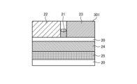
- FIGS. 1A and 1B are diagrams illustrating an example of a travel path of a working device according to an embodiment of the present disclosure.
- FIG. 1A is a diagram illustrating an example of a travel path for the working machine 10.
- the working machine 10 in the figure is assumed to be an excavator car that runs on caterpillars 11.
- the work machine 10 performs work of transporting objects such as earth and sand at a civil engineering work site or the like.
- a travel obstacle area such as a steep slope or a groove formed in the ground, which is an area that becomes an obstacle to travel.
- an object 21, slopes 22 and 23, and a groove 26 are shown as the travel obstacle area.
- Object 21 is a cube with sides angled at 90°.
- the slope 22 is assumed to be a slope with an angle of 25°
- the slope 23 is assumed to be a slope with an angle of 50°.
- the groove 26 is assumed to have a width of 2 m and a depth of 1 m. This groove 26 has a bottom surface 25 and a slope 24 having an angle of 90 degrees. Note that the ground 20 in the figure corresponds to a surface with an angle of 0°.
- the driving disorder area detection system of the present disclosure detects such a driving disorder area.
- a sensor 12 is arranged on the working machine 10 in the figure. This sensor 12 acquires an image of the surroundings of the work machine 10 and inputs it to the running obstacle area detection system.
- a distance measuring sensor that generates a distance image can be used as the sensor 12.
- the distance image is also referred to as a depth map, and is an image in which distance information is reflected for each pixel.
- FIG. 1B is a diagram schematically representing an image of the traveling path in FIG. 1A.
- a flat ground 20 In the image 301 of the figure, a flat ground 20, an object 21, slopes 22 and 23, and a slope 24 and a bottom 25 of a groove 26 are arranged.
- this image 301 as an example of a driving route, the operation of the driving obstacle area detection system of the present disclosure will be described.
- FIG. 2 is a diagram illustrating a configuration example of a driving obstacle area detection system according to an embodiment of the present disclosure. This figure is a block diagram showing an example of the configuration of the driving obstacle area detection system 100.
- the driving obstacle area detection system 100 includes a data converter 110, an area angle detector 120, an angle obstacle area detector 140, an area height detector 150, a height obstacle area detector 170, and a threshold generator 130. and 160, and a driving obstacle area detection section 180.
- the data conversion unit 110 converts a distance image, which is input data, into point cloud data.
- the point cloud data is output to the area angle detection section 120 and the area height detection section 150.
- the area angle detection unit 120 detects the angle of the running surface based on point cloud data. The detected angle is output to the angle failure area detection section 140.
- the angular obstacle area detection unit 140 detects an angular obstacle area that is an obstacle area based on the angle of the running surface.
- the detected angular obstacle area is output to the driving obstacle area detection section 180.
- the threshold value generation unit 130 generates a threshold value used for detecting an angular failure area in the angular failure area detection unit 140.
- the area height detection unit 150 detects the height of the running surface based on point cloud data. The detected height is output to the height fault area detection section 170.
- the height obstacle area detection unit 170 detects a height obstacle area that is an obstacle area based on the height of the running surface. The detected height obstacle area is output to the driving obstacle area detection section 180.
- the threshold value generation unit 160 generates a threshold value used for detecting a height failure area in the height failure area detection unit 170.
- the running obstacle area detection unit 180 detects a running obstacle area based on the angle obstacle area and the height obstacle area.
- the detected driving obstacle area is output to an external device, for example, a display device.
- FIG. 3 is a diagram illustrating an example of data conversion processing according to an embodiment of the present disclosure.
- This figure is a flowchart showing an example of data conversion processing (S110) in the data conversion unit 110.
- the input distance image is normalized (step S111).
- This normalization converts the distance image into point cloud data.
- This point group data is composed of an array of coordinates of each point on the x, y, and z axes.
- a known method can be applied to convert the distance image into point cloud data.
- step S112 downsampling is performed on the point cloud data.
- This downsampling is a process of thinning out row and column data for each of the x, y, and z axis coordinate arrays. This downsampling can reduce the processing amount and noise.
- step S113 coordinate correction is performed on the point group data after downsampling.
- This coordinate correction is a process of converting point cloud data into global coordinates.
- the sensor 12 shown in FIG. 1A is attached to the body of the working machine 10.
- the point cloud data is corrected according to the mounting height and mounting angle of the sensor 12.
- FIG. 4 is a diagram illustrating an example of angle detection processing according to the embodiment of the present disclosure.
- This figure is a flowchart showing an example of the angle detection process (S120) in the area angle detection unit 120.
- the area angle detection unit 120 selects a point of interest in the point cloud data (step S121).
- the area angle detection unit 120 generates an adjacent vector for the selected point of interest (step S122). This is a process of generating vectors directed toward two points adjacent to the point of interest in the row and column directions.
- the area angle detection unit 120 generates a normal vector (step S123). This can be generated by calculating the cross product of two adjacent vectors.
- the area angle detection unit 120 determines whether normal vectors have been calculated for all points (step S124). If the area angle detection unit 120 has generated normal vectors for all points (step S124, Yes), the process proceeds to step S125, and if there are points for which normal vectors have not been generated (step S124), the area angle detection unit 120 proceeds to step S125. , No) Select another point of interest (step S121).
- step S125 the area angle detection unit 120 selects a point of interest in the point cloud data (step S125).
- the area angle detection unit 120 calculates an angle for the selected point of interest (step S126). This can be done by calculating the inner product of the normal and the unit vector in the y-axis direction.
- the area angle detection unit 120 adjusts the angle sign (step S127). This inverts the sign of the angle when the slope angle is the depression angle. This can be done based on the values of the z-axis array of points. Specifically, the sign of the angle is reversed when the value of the z-axis array is a positive value.
- the area angle detection unit 120 determines whether angles have been calculated for all points (step S128).
- the area angle detection unit 120 ends the process when the angle has been calculated for all points (Step S128, Yes), and when there is a point for which the angle has not been calculated (Step S128, No), the area angle detection unit 120 terminates the process.
- a point of interest is selected (step S125).
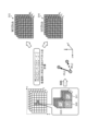
- FIG. 5 is a diagram illustrating an example of adjacent vector generation processing according to an embodiment of the present disclosure.
- ⁇ x'', ⁇ y'', and ⁇ z'' in the figure represent the coordinate arrays of the x, y, and z axes of the point group, respectively.
- a point of interest 310 is selected, and a point 311 adjacent to the point of interest 310 in the row direction and a point 312 adjacent to the point of interest in the column direction are selected.
- a W vector 313 directed from the point of interest 310 to the point 311 and an H vector 314 directed from the point of interest 310 to the point 312 are generated.
- FIG. 6 is a diagram illustrating an example of normal vector generation processing according to the embodiment of the present disclosure.
- the normal vector A can be calculated by calculating the cross product A of the W vector and the H vector and normalizing it with the norm "1".
- FIG. 7 is a diagram illustrating an example of angle calculation processing according to an embodiment of the present disclosure. As shown in the figure, the angle of the slope with respect to the horizontal direction can be calculated by calculating the inner product of the normal vector A and the unit vector "y" in the y-axis direction. The calculated angle is saved in the angle data array.
- FIG. 8 is a diagram illustrating an example of a detection angle according to an embodiment of the present disclosure.
- This figure is a diagram in which the angle detected by the area angle detection unit 120 is displayed superimposed on the image 301 of FIG. 1B.
- angles of 25° and 50° are added to slopes 22 and 23, respectively.
- an angle of 90° is added to the side surface of the object 21 and the slope 24 of the groove 26. 0° is added to areas other than these.
- FIG. 9 is a diagram illustrating an example of an angular obstacle area detection process according to an embodiment of the present disclosure. This figure is a flowchart showing an example of the angular fault area detection process S130 in the angular fault area detection unit 140.
- the angle failure area detection unit 140 calculates an absolute angle (step S131). This can be done by correcting the angle based on the inclination of work machine 10.
- the angular failure area detection unit 140 detects an angular failure area (step S132).
- the angular failure area detection unit 140 detects an angular failure area based on the threshold generated by the threshold generation unit 130.
- the threshold generation unit 130 can output a predetermined value, for example 30°, as the threshold.
- the angular failure area detection unit 140 can detect an area with an angle higher than this threshold value as an angular failure area.
- the threshold generation unit 130 can adjust the threshold according to information about the work machine 10.
- the information on the working machine 10 includes, for example, the weight, size, center of gravity, angle of the working machine 10, direction of movement (handle information), speed, and the like.
- the threshold generation unit 130 can adjust the threshold according to information about the surrounding environment.
- This information on the surrounding environment includes, for example, the weather, temperature, humidity, and the geology of the running surface. Note that information on the work machine 10 and information on the surrounding environment can be acquired from an external device, for example, a cloud server.
- FIG. 10 is a diagram illustrating an example of an angular obstruction region according to an embodiment of the present disclosure. This figure is a diagram in which the angular failure region is superimposed on the image 317 of FIG. 8. The area indicated by the dotted line in the image 321 in the figure corresponds to the angular failure area. As shown in the figure, an angular obstruction area 322 is added to the slope 23 with an angle of 50° and the side of the object 21 with an angle of 90°, and an angular obstruction area 323 is added to the slope 24 with an angle of 90°.
- FIG. 11 is a diagram illustrating an example of height failure area detection processing according to the embodiment of the present disclosure. This figure is a flowchart showing an example of the height failure area detection process (S140) in the height failure area detection unit 170. Note that the processing in the figure includes region height detection processing in the region height detection section 150.
- the area height detection unit 150 generates a height map (step S141).
- This height map is an array representing the height of each area.
- the y-axis coordinate arrangement described in FIG. 5 can be applied to the height map.
- the height failure area detection unit 170 detects a high position failure area (step S142). Specifically, the height failure area detection unit 170 detects an area higher than the high position threshold generated by the threshold generation unit 160 as a high position failure area. Further, the height obstacle area detection unit 170 detects a low-position obstacle area (step S143). Specifically, the height failure area detection unit 170 detects an area at a position lower than the low position threshold generated by the threshold value generation unit 160 as a low position failure area.
- the threshold generation unit 130 can output predetermined values as thresholds, for example, a high position threshold of 0.5 m and a low position threshold of ⁇ 0.5 m.
- the threshold generation unit 160 can adjust the threshold according to information about the work machine 10.
- the information on the working machine 10 includes, for example, the size of the working machine 10.
- FIG. 12 is a diagram illustrating an example of a height obstacle area according to an embodiment of the present disclosure.
- This figure is a diagram in which the height failure area is displayed superimposed on the image 317 of FIG. 8.
- the area indicated by the dashed line corresponds to the high-position failure area 332.
- the area indicated by the two-dot chain line corresponds to the low-position failure area 333.
- a high-position obstacle region 332 is added to the high-position regions of the slopes 22 and 23 and the upper surface of the object 21.
- a low-position obstacle area 333 is added to the low-position area of the slope 24 and the bottom surface 25.
- FIG. 13 is a diagram illustrating a configuration example of a driving obstacle area detection unit according to an embodiment of the present disclosure. This figure is a block diagram showing an example of the configuration of the driving obstacle area detection section 180.
- the driving obstacle area detection unit 180 includes an exception area detection unit 181, an object detection unit 182, and an occlusion area detection unit 183.
- the exceptional area detection unit 181 detects an exceptional area among the angle obstruction area and the height obstruction area.
- the angle obstacle area and the height obstacle area other than the exception area detected by the exception area detection unit 181 become the driving obstacle area.
- the object detection unit 182 detects an object placed on the running surface.
- the object detection unit 182 detects objects that may obstruct the running of a person or other work machine 10 or the like.
- the occlusion area detection unit 183 detects occlusion areas.
- This occlusion area is an area where the angle and height of the running surface cannot be detected. For example, an area hidden by a cliff or the like corresponds to an occlusion area. By detecting this occlusion area as a failure area, the safety of work machine 10 can be improved.
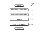
- FIG. 14 is a diagram illustrating an example of a driving obstacle area detection process according to an embodiment of the present disclosure.
- the same figure is a block diagram showing an example of processing in the driving obstacle area detection section 180.
- the exceptional area detection unit 181 detects an exceptional area of the angular obstruction area (step S151).
- This exceptional area corresponds to, for example, a slope area with a height lower than a predetermined threshold. This is because even if the slope has a steep angle, it can be climbed over as long as the slope is lower than the height of the caterpillar 11 of the working machine 10. The detected exception area is excluded from the angular failure area.
- the exceptional area detection unit 181 detects an exceptional area of the height failure area (step S152).
- This exceptional area corresponds to, for example, an area whose width is narrower than a predetermined threshold. This is because the groove 26 or the like having a relatively narrow width can be overcome. The detected exception area is excluded from the height failure area.
- the object detection unit 182 detects an object (step S153).
- the area of the detected object is added to the driving obstacle area.
- the occlusion area detection unit 183 detects an occlusion area (step S154).
- the detected occlusion area is added to the driving obstacle area.
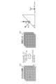
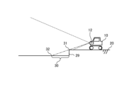
- FIG. 15 is a diagram illustrating an example of an occlusion area according to an embodiment of the present disclosure.
- This figure is a diagram showing how the sensor 12 of the work machine 10 detects a distance image of the running surface.
- the dotted line in the figure represents the field of view of the sensor 12.
- the area hidden by the cliff 31 at the top of the step 29 as seen from the sensor 12 becomes the occlusion area 30.
- the dashed line in the figure is a line connecting the sensor 12 and the cliff 31. If this one-dot chain line intersects with the ground 20 below the cliff 31 at a position 32, a discontinuous portion will occur in the distance image from the cliff 31 to the position 32.
- the occlusion area detection unit 183 can detect this area where the distance is discontinuous as the occlusion area 30.
- FIG. 16 is a diagram illustrating an example of a driving obstacle area detection process according to an embodiment of the present disclosure. This figure is a flowchart representing an example of processing in the driving obstacle area detection system 100.
- the data conversion unit 110 performs data conversion processing (step S110).
- the area angle detection unit 120 performs area angle detection processing (step S120).
- the angular failure area detection unit 140 performs angular failure area detection processing (step S130).
- the area height detection unit 150 and the height failure area detection unit 170 perform height failure area detection processing (step S140).
- the driving obstruction area detection unit 180 performs driving obstruction area detection processing (step S150).
- step S150 driving obstruction area detection processing
- the driving obstruction area detection system 100 of the present disclosure detects driving obstruction areas based on the angle and height of the driving surface, and thus can improve the ability to detect obstruction areas.
- the driving obstacle area detection system 100 of the present disclosure is applicable not only to work equipment at civil engineering construction sites, but also to general vehicles, construction machines, agricultural machines, forestry machines, disaster relief machines, nursing care and cleaning applications, for example. It can be applied to household machines, submarine probes, and planetary probes.
- the driving obstacle area detection system 100 of this embodiment may be realized by a dedicated computer system or a general-purpose computer system.
- a program for executing the above operations is stored and distributed in a computer-readable recording medium such as an optical disk, semiconductor memory, magnetic tape, or flexible disk. Then, for example, the program is installed on a computer and the control device is configured by executing the above-described processing.
- the communication program may be stored in a disk device included in a server device on a network such as the Internet, so that it can be downloaded to a computer.
- the above-mentioned functions may be realized through collaboration between an OS (Operating System) and application software.
- the parts other than the OS may be stored on a medium and distributed, or the parts other than the OS may be stored in a server device so that they can be downloaded to a computer.
- each component of each device shown in the drawings is functionally conceptual, and does not necessarily need to be physically configured as shown in the drawings.
- the specific form of distributing and integrating each device is not limited to what is shown in the diagram, and all or part of the devices can be functionally or physically distributed or integrated in arbitrary units depending on various loads and usage conditions. Can be integrated and configured. Note that this distribution/integration configuration may be performed dynamically.
- the present embodiment can be applied to any configuration constituting a device or system, such as a processor as a system LSI (Large Scale Integration), a module using multiple processors, a unit using multiple modules, etc. Furthermore, it can also be implemented as a set (that is, a partial configuration of the device) with additional functions.
- a processor as a system LSI (Large Scale Integration)
- a module using multiple processors a unit using multiple modules, etc.
- it can also be implemented as a set (that is, a partial configuration of the device) with additional functions.
- a system means a collection of multiple components (devices, modules (components), etc.), and it does not matter whether all the components are in the same housing or not. Therefore, multiple devices housed in separate casings and connected via a network, and a single device with multiple modules housed in one casing are both systems. .
- the present embodiment can take a cloud computing configuration in which one function is shared and jointly processed by a plurality of devices via a network.
- the processing procedure described in the above embodiment may be regarded as a method having a series of these procedures, and may also be used as a program for causing a computer to execute this series of procedures or a recording medium that stores the program. You can capture it.
- this recording medium include flexible discs, CD-ROMs (Compact Disc Read Only Memory), MO (Magnet optical) discs, DVDs (Digital Versatile Discs), Blu-ray discs (Blu-ray (registered trademark) Discs), and magnetic discs.
- a semiconductor memory, a memory card, etc. can be used.
- a system for detecting a travel obstacle area that is an area that impedes the travel of a working machine comprising: an area angle detection unit that detects an angle of a running surface based on a distance image around the work machine; an area height detection unit that detects the height of the running surface based on the distance image; an angle failure area detection unit that detects an angle failure area that is a failure area based on the detected angle; a height failure area detection unit that detects a height failure area that is a failure area based on the detected height;
- a system comprising: a driving obstacle area detection unit that detects the driving obstacle area based on the detected angle obstacle area and the detected height obstacle area.
- (9) further comprising an occlusion area detection unit that detects an occlusion area in which the angle and the height on the running surface cannot be detected;
- the driving obstruction area detection unit further detects the detected occlusion area as the driving obstruction area.
Landscapes
- Engineering & Computer Science (AREA)
- Physics & Mathematics (AREA)
- General Physics & Mathematics (AREA)
- Theoretical Computer Science (AREA)
- Computer Vision & Pattern Recognition (AREA)
- Structural Engineering (AREA)
- General Engineering & Computer Science (AREA)
- Civil Engineering (AREA)
- Mining & Mineral Resources (AREA)
- Geometry (AREA)
- Aviation & Aerospace Engineering (AREA)
- Radar, Positioning & Navigation (AREA)
- Remote Sensing (AREA)
- Automation & Control Theory (AREA)
- Component Parts Of Construction Machinery (AREA)
- Guiding Agricultural Machines (AREA)
- Control Of Position, Course, Altitude, Or Attitude Of Moving Bodies (AREA)
Abstract
Description
図1A及び1Bは、本開示の実施形態に係る作業装置の走行路の一例を示す図である。図1Aは、作業機械10の走行路の一例を表す図である。同図の作業機械10は、キャタピラ11により走行するショベルカーを想定したものである。作業機械10は、土木工事現場等において土砂等の物体を運搬する作業を行う。工事現場等には、急勾配の坂や地面に形成された溝等の走行の障害となる領域である走行障害領域が存在する場合がある。この走行障害領域として、同図には、物体21、坂22及び23並びに溝26を記載した。物体21は、角度90°の側面を有する立方体である。坂22は角度25°の斜面を想定し、坂23は角度50°の斜面を想定したものである。また、溝26は、幅2m、深さ1mの溝を想定したものである。この溝26は、底面25及び角度90°の法面24を有する。なお、同図の地面20は、角度0°の面に相当する。
図2は、本開示の実施形態に係る走行障害領域検出システムの構成例を示す図である。同図は、走行障害領域検出システム100の構成例を表すブロック図である。走行障害領域検出システム100は、データ変換部110と、領域角度検出部120と、角度障害領域検出部140と、領域高さ検出部150と、高さ障害領域検出部170と、閾値生成部130及び160と、走行障害領域検出部180とを備える。
図3は、本開示の実施形態に係るデータ変換処理の一例を示す図である。同図は、データ変換部110におけるデータ変換処理(S110)の一例を表す流れ図である。まず、入力される距離画像の正規化を行う(ステップS111)。この正規化は、距離画像を点群データに変換するものである。この点群データは、それぞれの点のx、y及びz軸の座標の配列により構成される。距離画像の点群データへの変換には、公知の方法を適用することができる。
図4は、本開示の実施形態に係る角度検出処理の一例を示す図である。同図は、領域角度検出部120における角度検出処理(S120)の一例を表す流れ図である。まず、領域角度検出部120は、点群データの注目点を選択する(ステップS121)。次に、領域角度検出部120は、選択した注目点に対して隣接ベクトルを生成する(ステップS122)。これは、注目点の行方向及び列方向に隣接する2つの点に向かうベクトルを生成する処理である。次に、領域角度検出部120は、法線ベクトルを生成する(ステップS123)。これは、隣接する2つのベクトルの外積を算出することにより生成することができる。次に、領域角度検出部120は、全ての点について法線ベクトルを算出したかを判断する(ステップS124)。領域角度検出部120は、全ての点について法線ベクトルを生成した場合には(ステップS124,Yes)ステップS125に移行し、法線ベクトルを生成していない点が存在する場合には(ステップS124,No)他の注目点を選択する(ステップS121)。
図5は、本開示の実施形態に係る隣接ベクトル生成処理の一例を示す図である。同図の「x」、「y」及び「z」は、それぞれ点群のx、y及びz軸の座標の配列を表す。これらうち注目点310を選択し、この注目点310の行方向に隣接する点311及び列方向に隣接する点312を選択する。そして注目点310から点311に向かうWベクトル313及び注目点310から点312に向かうHベクトル314を生成する。
図6は、本開示の実施形態に係る法線ベクトル生成処理の一例を示す図である。同図に表したように、Wベクトル及びHベクトルの外積Aを算出し、ノルム「1」にて規格化することにより、法線ベクトルAを算出することができる。
図7は、本開示の実施形態に係る角度算出処理の一例を示す図である。同図に表したように、法線ベクトルAとy軸方向の単位ベクトル「y」の内積を算出することにより、斜面の水平方向に対する角度を算出することができる。算出した角度は、角度データ配列に保存される。
図8は、本開示の実施形態に係る検出角度の一例を示す図である。同図は、領域角度検出部120により検出した角度を図1Bの画像301に重ね合わせて表示した図である。同図の画像317において、坂22及び23には、それぞれ25°及び50°の角度が付加される。また、物体21の側面及び溝26の法面24には、90゜の角度が付加される。これら以外の領域には、0°が付加される。
図9は、本開示の実施形態に係る角度障害領域検出処理の一例を示す図である。同図は、角度障害領域検出部140における角度障害領域検出処理S130の一例を表す流れ図である。まず、角度障害領域検出部140は、絶対角度を算出する(ステップS131)。これは、作業機械10の傾きに基づいて角度を補正することにより行うことができる。
図10は、本開示の実施形態に係る角度障害領域の一例を示す図である。同図は、図8の画像317に角度障害領域を重ね合わせて表示した図である。同図の画像321において点線により表した領域が角度障害領域に該当する。同図に表したように、角度50°の坂23及び角度90°の物体21の側面に角度障害領域322が付加され、角度90°の法面24に角度障害領域323が付加される。
図11は、本開示の実施形態に係る高さ障害領域検出処理の一例を示す図である。同図は、高さ障害領域検出部170における高さ障害領域検出処理(S140)の一例を表す流れ図である。なお、同図の処理には、領域高さ検出部150における領域高さ検出処理が含まれる。
図12は、本開示の実施形態に係る高さ障害領域の一例を示す図である。同図は、図8の画像317に高さ障害領域を重ね合わせて表示した図である。同図の画像331において一点鎖線により表した領域が高位置障害領域332に該当する。また、同図の画像331において二点鎖線により表した領域が低位置障害領域333に該当する。同図に表したように、坂22及び23の高位置の領域並びに物体21の上面に高位置障害領域332が付加される。また、法面24の低位置の領域及び底面25に低位置障害領域333が付加される。
図13は、本開示の実施形態に係る走行障害領域検出部の構成例を示す図である。同図は、走行障害領域検出部180の構成例を表すブロック図である。走行障害領域検出部180は、例外領域検出部181と、物体検出部182と、オクルージョン領域検出部183とを備える。
図14は、本開示の実施形態に係る走行障害領域検出処理の一例を示す図である。同図は、走行障害領域検出部180における処理の一例を表すブロック図である。まず、例外領域検出部181が角度障害領域の例外領域を検出する(ステップS151)。この例外領域には、例えば、所定の閾値より低い高さの坂の領域が該当する。急峻な角度の斜面であっても、作業機械10のキャタピラ11の高さと比較して低い高さの領域であれば乗り越えられるためである。検出された例外領域は、角度障害領域から除外される。
図15は、本開示の実施形態に係るオクルージョン領域の一例を示す図である。同図は、作業機械10のセンサ12により走行面の距離画像を検出する様子を表した図である。同図の点線は、センサ12の視野を表す。同図の地面20には、段差29が存在する。センサ12から見た段差29の上部の崖31に隠れた領域がオクルージョン領域30となる。同図の一点鎖線は、センサ12と崖31とを結ぶ線である。この一点鎖線が崖31下の地面20と交わる位置32とすると、距離画像において崖31から位置32において距離が不連続の部分を生じる。オクルージョン領域検出部183は、この距離が不連続の領域をオクルージョン領域30として検出することができる。
図16は、本開示の実施形態に係る走行障害領域検出処理の一例を示す図である。同図は、走行障害領域検出システム100における処理の一例を表す流れ図である。まず、データ変換部110がデータ変換処理(ステップS110)を行う。次に、領域角度検出部120が領域角度検出処理(ステップS120)を行う。次に、角度障害領域検出部140が角度障害領域検出処理(ステップS130)を行う。次に、領域高さ検出部150及び高さ障害領域検出部170が高さ障害領域検出処理(ステップS140)を行う。次に、走行障害領域検出部180が、走行障害領域検出処理(ステップS150)を行う。以上の処理により走行障害領域を検出することができる。検出した走行障害領域は、外部の装置に対して出力される。
本実施形態の走行障害領域検出システム100は、専用のコンピュータシステムにより実現してもよいし、汎用のコンピュータシステムによって実現してもよい。
(1)
作業機械の走行の障害となる領域である走行障害領域を検出するシステムであって、
前記作業機械の周囲の距離画像に基づいて走行面の角度を検出する領域角度検出部と、
前記距離画像に基づいて前記走行面の高さを検出する領域高さ検出部と、
前記検出した角度に基づく障害領域である角度障害領域を検出する角度障害領域検出部と、
前記検出した高さに基づく障害領域である高さ障害領域を検出する高さ障害領域検出部と、
前記検出された角度障害領域及び前記検出された高さ障害領域に基づいて前記走行障害領域を検出する走行障害領域検出部と
を有するシステム。
(2)
前記角度障害領域検出部は、前記角度の閾値に基づいて前記角度障害領域を検出する前記(1)に記載のシステム。
(3)
前記角度障害領域検出部は、前記作業機械の情報に応じて調整された前記閾値に基づいて前記角度障害領域を検出する前記(2)に記載のシステム。
(4)
前記角度障害領域検出部は、周囲環境の情報に応じて調整された前記閾値に基づいて前記角度障害領域を検出する前記(2)に記載のシステム。
(5)
前記高さ障害領域検出部は、前記高さの閾値に基づいて前記高さ障害領域を検出する前記(1)から(4)の何れかに記載のシステム。
(6)
前記走行障害領域検出部は、前記検出された角度障害領域のうち所定の高さの領域を除外することにより前記走行障害領域を検出する前記(1)から(5)の何れかに記載のシステム。
(7)
前記走行障害領域検出部は、前記検出された高さ障害領域のうち所定の幅の領域を除外することにより前記走行障害領域を検出する前記(1)から(6)の何れかに記載のシステム。
(8)
前記走行面に載置された物体を検出する物体検出部
を更に有し、
前記走行障害領域検出部は、前記検出された物体の領域を前記走行障害領域として更に検出する
前記(1)から(7)の何れかに記載のシステム。
(9)
前記走行面における前記角度及び前記高さを検出できない領域であるオクルージョン領域を検出するオクルージョン領域検出部を
更に有し、
前記走行障害領域検出部は、前記検出されたオクルージョン領域を前記走行障害領域として更に検出する
前記(1)から(8)の何れかに記載のシステム。
(10)
作業機械の走行の障害となる領域である走行障害領域を検出するプログラムであって、
前記作業機械の周囲の距離画像に基づいて走行面の角度を検出する領域角度検出手順と、
前記距離画像に基づいて前記走行面の高さを検出する領域高さ検出手順と、
前記検出した角度に基づく障害領域である角度障害領域を検出する角度障害領域検出手順と、
前記検出した高さに基づく障害領域である高さ障害領域を検出する高さ障害領域検出手順と、
前記検出された角度障害領域及び前記検出された高さ障害領域に基づいて前記走行障害領域を検出する走行障害領域検出手順と
を含むプログラム。
12 センサ
100 走行障害領域検出システム
110 データ変換部
120 領域角度検出部
130 閾値生成部
140 角度障害領域検出部
150 領域高さ検出部
160 閾値生成部
170 高さ障害領域検出部
180 走行障害領域検出部
181 例外領域検出部
182 物体検出部
183 オクルージョン領域検出部
Claims (10)
- 作業機械の走行の障害となる領域である走行障害領域を検出するシステムであって、
前記作業機械の周囲の距離画像に基づいて走行面の角度を検出する領域角度検出部と、
前記距離画像に基づいて前記走行面の高さを検出する領域高さ検出部と、
前記検出した角度に基づく障害領域である角度障害領域を検出する角度障害領域検出部と、
前記検出した高さに基づく障害領域である高さ障害領域を検出する高さ障害領域検出部と、
前記検出された角度障害領域及び前記検出された高さ障害領域に基づいて前記走行障害領域を検出する走行障害領域検出部と
を有するシステム。 - 前記角度障害領域検出部は、前記角度の閾値に基づいて前記角度障害領域を検出する請求項1に記載のシステム。
- 前記角度障害領域検出部は、前記作業機械の情報に応じて調整された前記閾値に基づいて前記角度障害領域を検出する請求項2に記載のシステム。
- 前記角度障害領域検出部は、周囲環境の情報に応じて調整された前記閾値に基づいて前記角度障害領域を検出する請求項2に記載のシステム。
- 前記高さ障害領域検出部は、前記高さの閾値に基づいて前記高さ障害領域を検出する請求項1に記載のシステム。
- 前記走行障害領域検出部は、前記検出された角度障害領域のうち所定の高さの領域を除外することにより前記走行障害領域を検出する請求項1に記載のシステム。
- 前記走行障害領域検出部は、前記検出された高さ障害領域のうち所定の幅の領域を除外することにより前記走行障害領域を検出する請求項1に記載のシステム。
- 前記走行面に載置された物体を検出する物体検出部
を更に有し、
前記走行障害領域検出部は、前記検出された物体の領域を前記走行障害領域として更に検出する
請求項1に記載のシステム。 - 前記走行面における前記角度及び前記高さを検出できない領域であるオクルージョン領域を検出するオクルージョン領域検出部
を更に有し、
前記走行障害領域検出部は、前記検出されたオクルージョン領域を前記走行障害領域として更に検出する
請求項1に記載のシステム。 - 作業機械の走行の障害となる領域である走行障害領域を検出するプログラムであって、
前記作業機械の周囲の距離画像に基づいて走行面の角度を検出する領域角度検出手順と、
前記距離画像に基づいて前記走行面の高さを検出する領域高さ検出手順と、
前記検出した角度に基づく障害領域である角度障害領域を検出する角度障害領域検出手順と、
前記検出した高さに基づく障害領域である高さ障害領域を検出する高さ障害領域検出手順と、
前記検出された角度障害領域及び前記検出された高さ障害領域に基づいて前記走行障害領域を検出する走行障害領域検出手順と
を含むプログラム。
Priority Applications (3)
| Application Number | Priority Date | Filing Date | Title |
|---|---|---|---|
| JP2024532032A JPWO2024009803A1 (ja) | 2022-07-04 | 2023-06-23 | |
| US18/872,283 US20250361698A1 (en) | 2022-07-04 | 2023-06-23 | System and program |
| CN202380050758.3A CN119487548A (zh) | 2022-07-04 | 2023-06-23 | 系统和程序 |
Applications Claiming Priority (2)
| Application Number | Priority Date | Filing Date | Title |
|---|---|---|---|
| JP2022107769 | 2022-07-04 | ||
| JP2022-107769 | 2022-07-04 |
Publications (1)
| Publication Number | Publication Date |
|---|---|
| WO2024009803A1 true WO2024009803A1 (ja) | 2024-01-11 |
Family
ID=89453278
Family Applications (1)
| Application Number | Title | Priority Date | Filing Date |
|---|---|---|---|
| PCT/JP2023/023283 Ceased WO2024009803A1 (ja) | 2022-07-04 | 2023-06-23 | システム及びプログラム |
Country Status (4)
| Country | Link |
|---|---|
| US (1) | US20250361698A1 (ja) |
| JP (1) | JPWO2024009803A1 (ja) |
| CN (1) | CN119487548A (ja) |
| WO (1) | WO2024009803A1 (ja) |
Families Citing this family (1)
| Publication number | Priority date | Publication date | Assignee | Title |
|---|---|---|---|---|
| JP2025117599A (ja) * | 2024-01-31 | 2025-08-13 | ヤンマーホールディングス株式会社 | 作業車両の制御方法、作業車両制御プログラム、作業車両制御システム及び作業車両 |
Citations (3)
| Publication number | Priority date | Publication date | Assignee | Title |
|---|---|---|---|---|
| JP2006146376A (ja) * | 2004-11-17 | 2006-06-08 | Mitsubishi Heavy Ind Ltd | 自立移動ロボット及び移動不能領域検出方法 |
| JP2015219802A (ja) * | 2014-05-20 | 2015-12-07 | 株式会社国際電気通信基礎技術研究所 | 経路算出装置、経路算出プログラムおよび経路算出方法 |
| JP2021077003A (ja) * | 2019-11-07 | 2021-05-20 | 本田技研工業株式会社 | 走破可否判定装置及び移動体の制御装置 |
Family Cites Families (22)
| Publication number | Priority date | Publication date | Assignee | Title |
|---|---|---|---|---|
| US10809071B2 (en) * | 2017-10-17 | 2020-10-20 | AI Incorporated | Method for constructing a map while performing work |
| DE102015010009A1 (de) * | 2015-08-05 | 2017-02-09 | Wirtgen Gmbh | Selbstfahrende Baumaschine und Verfahren zur Anzeige der Umgebung einer selbstfahrenden Baumaschine |
| US9928648B2 (en) * | 2015-11-09 | 2018-03-27 | Microsoft Technology Licensing, Llc | Object path identification for navigating objects in scene-aware device environments |
| JP6677513B2 (ja) * | 2016-01-07 | 2020-04-08 | シャープ株式会社 | 自律走行装置 |
| US11927965B2 (en) * | 2016-02-29 | 2024-03-12 | AI Incorporated | Obstacle recognition method for autonomous robots |
| US11037320B1 (en) * | 2016-03-01 | 2021-06-15 | AI Incorporated | Method for estimating distance using point measurement and color depth |
| TWI652034B (zh) * | 2016-05-17 | 2019-03-01 | Lg電子股份有限公司 | 清掃機器人 |
| US9880561B2 (en) * | 2016-06-09 | 2018-01-30 | X Development Llc | Sensor trajectory planning for a vehicle |
| DE102016118227A1 (de) * | 2016-09-27 | 2018-03-29 | Claas Selbstfahrende Erntemaschinen Gmbh | Bildanlysesystem für landwirtschaftliche Arbeitsmaschinen |
| JP6739364B2 (ja) * | 2017-01-20 | 2020-08-12 | 株式会社クボタ | 自動走行作業車 |
| US10037613B1 (en) * | 2017-03-30 | 2018-07-31 | Uber Technologies, Inc. | Systems and methods to track vehicles proximate perceived by an autonomous vehicle |
| JP6928499B2 (ja) * | 2017-07-21 | 2021-09-01 | 株式会社タダノ | ガイド情報表示装置および作業機 |
| JP6871097B2 (ja) * | 2017-07-21 | 2021-05-12 | 株式会社タダノ | ガイド情報表示装置およびこれを備えた作業機およびガイド情報表示方法 |
| US11348269B1 (en) * | 2017-07-27 | 2022-05-31 | AI Incorporated | Method and apparatus for combining data to construct a floor plan |
| US11254547B2 (en) * | 2018-02-02 | 2022-02-22 | Tulsa Winch, Inc. | Work area monitoring system for lifting machines |
| EP3797339B1 (en) * | 2018-05-22 | 2025-03-12 | Starship Technologies OÜ | Method and system for automatic autonomous road crossing |
| US11179850B2 (en) * | 2019-04-24 | 2021-11-23 | Intrinsic Innovation Llc | Robot motion planning |
| CN112925351B (zh) * | 2019-12-06 | 2022-08-02 | 杭州萤石软件有限公司 | 一种视觉机器光源控制方法、装置 |
| WO2023003867A2 (en) * | 2021-07-19 | 2023-01-26 | Clark Equipment Company | Systems and methods for obstacle detection for a power machine |
| JP2023169512A (ja) * | 2022-05-17 | 2023-11-30 | キヤノン株式会社 | 監視システム、監視システムの制御方法およびプログラム |
| US20250013245A1 (en) * | 2023-07-07 | 2025-01-09 | Yanmar Holdings Co., Ltd. | Vehicle control method, vehicle control program, and vehicle control system |
| CN118235999A (zh) * | 2024-04-18 | 2024-06-25 | 追觅创新科技(苏州)有限公司 | 清洁机器人的行进控制方法、清洁机器人以及存储介质 |
-
2023
- 2023-06-23 WO PCT/JP2023/023283 patent/WO2024009803A1/ja not_active Ceased
- 2023-06-23 US US18/872,283 patent/US20250361698A1/en active Pending
- 2023-06-23 CN CN202380050758.3A patent/CN119487548A/zh active Pending
- 2023-06-23 JP JP2024532032A patent/JPWO2024009803A1/ja active Pending
Patent Citations (3)
| Publication number | Priority date | Publication date | Assignee | Title |
|---|---|---|---|---|
| JP2006146376A (ja) * | 2004-11-17 | 2006-06-08 | Mitsubishi Heavy Ind Ltd | 自立移動ロボット及び移動不能領域検出方法 |
| JP2015219802A (ja) * | 2014-05-20 | 2015-12-07 | 株式会社国際電気通信基礎技術研究所 | 経路算出装置、経路算出プログラムおよび経路算出方法 |
| JP2021077003A (ja) * | 2019-11-07 | 2021-05-20 | 本田技研工業株式会社 | 走破可否判定装置及び移動体の制御装置 |
Also Published As
| Publication number | Publication date |
|---|---|
| US20250361698A1 (en) | 2025-11-27 |
| CN119487548A (zh) | 2025-02-18 |
| JPWO2024009803A1 (ja) | 2024-01-11 |
Similar Documents
| Publication | Publication Date | Title |
|---|---|---|
| US11560690B2 (en) | Techniques for kinematic and dynamic behavior estimation in autonomous vehicles | |
| CN109084746B (zh) | 用于具有辅助传感器的自主平台引导系统的单目模式 | |
| US20220308580A1 (en) | Redundant Lateral Velocity Determination and Use in Secondary Vehicle Control Systems | |
| US20100315505A1 (en) | Object motion detection system based on combining 3d warping techniques and a proper object motion detection | |
| JP2020118020A (ja) | 車両の横転を防止するためのシステムおよび方法 | |
| CN121120760A (zh) | 计算机视觉系统中的碰撞时间估计 | |
| JP2023023659A (ja) | 地図作成システムおよび地図作成方法 | |
| JP2010134742A (ja) | 障害物回避機能を有する移動制御装置 | |
| US11971257B2 (en) | Method and apparatus with localization | |
| KR101877001B1 (ko) | 가상 라인 생성 방법, 역주행 검출 시스템 및 그 방법 | |
| WO2018221455A1 (ja) | 更新装置、制御方法、プログラム及び記憶媒体 | |
| WO2024009803A1 (ja) | システム及びプログラム | |
| US10775804B1 (en) | Optical array sensor for use with autonomous vehicle control systems | |
| US12535322B2 (en) | System and methods of vehicle pose estimation | |
| WO2022232747A1 (en) | Systems and methods for producing amodal cuboids | |
| CN117795378A (zh) | 用于粒子滤波器跟踪的系统和方法 | |
| AU2015200255B2 (en) | System and method for estimation of machine position | |
| WO2021106510A1 (ja) | 障害物認識装置 | |
| US12503135B2 (en) | Localization algorithm | |
| Moreno et al. | Hypergrid: A Hyper-Fast ROS-Based Framework for Local Map Generation | |
| WO2022124115A1 (ja) | 情報処理装置、制御方法、プログラム及び記憶媒体 | |
| EP3731130B1 (en) | Apparatus for determining an occupancy map | |
| JP7701101B2 (ja) | 地図生成装置、地図生成方法、及びプログラム | |
| US11718320B1 (en) | Using transmission sensor(s) in localization of an autonomous vehicle | |
| US20230033908A1 (en) | Ground plane cancellation for collision avoidance system |
Legal Events
| Date | Code | Title | Description |
|---|---|---|---|
| 121 | Ep: the epo has been informed by wipo that ep was designated in this application |
Ref document number: 23835337 Country of ref document: EP Kind code of ref document: A1 |
|
| WWE | Wipo information: entry into national phase |
Ref document number: 2024532032 Country of ref document: JP |
|
| WWE | Wipo information: entry into national phase |
Ref document number: 18872283 Country of ref document: US |
|
| WWE | Wipo information: entry into national phase |
Ref document number: 202380050758.3 Country of ref document: CN |
|
| NENP | Non-entry into the national phase |
Ref country code: DE |
|
| WWP | Wipo information: published in national office |
Ref document number: 202380050758.3 Country of ref document: CN |
|
| 122 | Ep: pct application non-entry in european phase |
Ref document number: 23835337 Country of ref document: EP Kind code of ref document: A1 |
|
| WWP | Wipo information: published in national office |
Ref document number: 18872283 Country of ref document: US |