WO2024009588A1 - 加工公差評価システム - Google Patents
加工公差評価システム Download PDFInfo
- Publication number
- WO2024009588A1 WO2024009588A1 PCT/JP2023/015903 JP2023015903W WO2024009588A1 WO 2024009588 A1 WO2024009588 A1 WO 2024009588A1 JP 2023015903 W JP2023015903 W JP 2023015903W WO 2024009588 A1 WO2024009588 A1 WO 2024009588A1
- Authority
- WO
- WIPO (PCT)
- Prior art keywords
- machining
- tolerance
- workpiece
- processing
- theoretical
- Prior art date
- Legal status (The legal status is an assumption and is not a legal conclusion. Google has not performed a legal analysis and makes no representation as to the accuracy of the status listed.)
- Ceased
Links
Images


Classifications
-
- B—PERFORMING OPERATIONS; TRANSPORTING
- B23—MACHINE TOOLS; METAL-WORKING NOT OTHERWISE PROVIDED FOR
- B23Q—DETAILS, COMPONENTS, OR ACCESSORIES FOR MACHINE TOOLS, e.g. ARRANGEMENTS FOR COPYING OR CONTROLLING; MACHINE TOOLS IN GENERAL CHARACTERISED BY THE CONSTRUCTION OF PARTICULAR DETAILS OR COMPONENTS; COMBINATIONS OR ASSOCIATIONS OF METAL-WORKING MACHINES, NOT DIRECTED TO A PARTICULAR RESULT
- B23Q17/00—Arrangements for observing, indicating or measuring on machine tools
- B23Q17/09—Arrangements for observing, indicating or measuring on machine tools for indicating or measuring cutting pressure or for determining cutting-tool condition, e.g. cutting ability, load on tool
-
- B—PERFORMING OPERATIONS; TRANSPORTING
- B24—GRINDING; POLISHING
- B24B—MACHINES, DEVICES, OR PROCESSES FOR GRINDING OR POLISHING; DRESSING OR CONDITIONING OF ABRADING SURFACES; FEEDING OF GRINDING, POLISHING, OR LAPPING AGENTS
- B24B49/00—Measuring or gauging equipment for controlling the feed movement of the grinding tool or work; Arrangements of indicating or measuring equipment, e.g. for indicating the start of the grinding operation
- B24B49/16—Measuring or gauging equipment for controlling the feed movement of the grinding tool or work; Arrangements of indicating or measuring equipment, e.g. for indicating the start of the grinding operation taking regard of the load
-
- G—PHYSICS
- G05—CONTROLLING; REGULATING
- G05B—CONTROL OR REGULATING SYSTEMS IN GENERAL; FUNCTIONAL ELEMENTS OF SUCH SYSTEMS; MONITORING OR TESTING ARRANGEMENTS FOR SUCH SYSTEMS OR ELEMENTS
- G05B19/00—Program-control systems
- G05B19/02—Program-control systems electric
- G05B19/18—Numerical control [NC], i.e. automatically operating machines, in particular machine tools, e.g. in a manufacturing environment, so as to execute positioning, movement or co-ordinated operations by means of program data in numerical form
- G05B19/406—Numerical control [NC], i.e. automatically operating machines, in particular machine tools, e.g. in a manufacturing environment, so as to execute positioning, movement or co-ordinated operations by means of program data in numerical form characterised by monitoring or safety
- G05B19/4069—Simulating machining process on screen
-
- G—PHYSICS
- G05—CONTROLLING; REGULATING
- G05B—CONTROL OR REGULATING SYSTEMS IN GENERAL; FUNCTIONAL ELEMENTS OF SUCH SYSTEMS; MONITORING OR TESTING ARRANGEMENTS FOR SUCH SYSTEMS OR ELEMENTS
- G05B19/00—Program-control systems
- G05B19/02—Program-control systems electric
- G05B19/418—Total factory control, i.e. centrally controlling a plurality of machines, e.g. direct or distributed numerical control [DNC], flexible manufacturing systems [FMS], integrated manufacturing systems [IMS] or computer integrated manufacturing [CIM]
-
- Y—GENERAL TAGGING OF NEW TECHNOLOGICAL DEVELOPMENTS; GENERAL TAGGING OF CROSS-SECTIONAL TECHNOLOGIES SPANNING OVER SEVERAL SECTIONS OF THE IPC; TECHNICAL SUBJECTS COVERED BY FORMER USPC CROSS-REFERENCE ART COLLECTIONS [XRACs] AND DIGESTS
- Y02—TECHNOLOGIES OR APPLICATIONS FOR MITIGATION OR ADAPTATION AGAINST CLIMATE CHANGE
- Y02P—CLIMATE CHANGE MITIGATION TECHNOLOGIES IN THE PRODUCTION OR PROCESSING OF GOODS
- Y02P90/00—Enabling technologies with a potential contribution to greenhouse gas [GHG] emissions mitigation
- Y02P90/02—Total factory control, e.g. smart factories, flexible manufacturing systems [FMS] or integrated manufacturing systems [IMS]
Definitions
- the present invention relates to a processing tolerance evaluation system that can determine and display the manufacturable tolerance range of metal processed products.
- Patent Document 1 describes a variation analysis method for determining variation in characteristics of a product having one or more standard-limited variation parameters.
- the variation analysis method of Patent Document 1 includes a variation distribution estimation procedure for obtaining normal distribution parameters based on sample data for each standard-restricted variation parameter, and a value determined using random numbers for each standard-restricted variation parameter.
- a Monte Carlo analysis procedure that repeats simulation multiple times using the values of If the tentative value is within the standard range, it will be made the official value, and if the tentative value is outside the standard range, a uniform random number will be set again within the standard range. This is used to obtain a temporary value, which is then used as the official value.
- Monte Carlo analysis can be performed within a standard-limited range without unnecessarily increasing the number of times of value setting using random numbers for each variable parameter. Furthermore, the accuracy of variation analysis can be improved by making the normal distribution parameter for each variation parameter closer to the actual variation. For this reason, it is possible to predict, for example, variations in characteristics of a product constructed by assembling elemental parts.
- the present invention has been made in view of the above-mentioned problems, and an object of the present invention is to provide a processing tolerance evaluation system that can reduce at least rework costs by determining and displaying an appropriate tolerance range in which metal processed products can be manufactured. With the goal.
- the present invention includes a plurality of means for solving at least one of the above problems, examples of which are as follows.
- a machining tolerance evaluation system includes an on-site computer equipped with a storage area for holding manufacturing process data acquired from a manufacturing site, and a on-site computer connected to the on-site computer through a communication means.
- a machining tolerance evaluation system comprising a machining tolerance evaluation calculator, the machining tolerance evaluation calculator at least acquires manufacturing process data from an on-site computer, and calculates machining tolerances based on the acquired manufacturing process data.
- a machining tolerance width evaluation calculation block that has the function of determining the upper limit machining tolerance and the lower limit machining tolerance
- a theoretical machining error calculation block that has the function of determining the theoretical machining error of the workpiece calculated from physical analysis
- the theoretical machining It has a function to calculate and display the manufacturable tolerance range by reflecting the upper limit machining tolerance and lower limit machining tolerance determined by the machining tolerance width evaluation calculation block against the theoretical machining error determined by the error calculation block. It is characterized by being equipped with a tolerance range display calculation block.
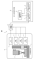
- FIG. 1 is a configuration diagram showing the configuration of a processing tolerance evaluation system according to a typical embodiment of the present invention.
- 2 is a configuration diagram showing the configuration of the on-site computer shown in FIG. 1.
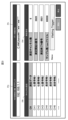
- FIG. 3 is an explanatory diagram illustrating a display example of a screen of the user interface shown in FIG. 2.
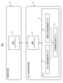
- FIG. 2 is a configuration diagram showing the configuration of the processing tolerance evaluation computer shown in FIG. 1.
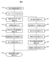
- FIG. It is a flowchart of the process of determining and displaying an appropriate tolerance range in the machining tolerance evaluation calculator.
- 6 is an explanatory diagram illustrating a tolerance range obtained by executing the flowchart of FIG. 5.
- FIG. 5 is a configuration diagram showing the configuration of a processing tolerance evaluation system according to a typical embodiment of the present invention.
- FIG. 1 shows a configuration example of a machining tolerance evaluation system 1 according to an embodiment of the present invention.
- the machining tolerance evaluation system 1 includes an NC cutting machine 10, an on-site calculator 20, and a machining tolerance evaluation calculator 30.
- the NC cutting machine 10 includes an NC cutting machine body 11, an electric motor, a cutting tool, and a drill. , a processing tool 12 such as a grindstone, a workpiece (metal processing product) 13, an NC controller 14 for controlling the operation of the NC cutting machine main body 11, and an external sensor 15.
- the external sensor detects information regarding the operation of the NC processing machine body, such as a current sensor, a temperature sensor, and a vibration sensor.
- the on-site computer 20 includes a connection interface (not shown) that can communicate with the NC controller 14 and a connection interface (not shown) that can receive sensor detection information from the external sensor 15. Note that, as is well known, there is no limit to the number of external sensors 15 that can be connected. The configuration of this on-site computer 20 will be explained with reference to FIG.
- the processing tolerance evaluation computer 30 is equipped with an interface (not shown) that can communicate information with the on-site computer 20.
- the NC cutting machine 10 is generally installed at a processing site such as a manufacturing factory, but the on-site calculator 20 and the processing tolerance evaluation calculator 30 are not necessarily the same as the NC cutting machine 10. There is no need to install it anywhere.
- the on-site computer 20 and the machining tolerance evaluation computer 30 are connected to the NC controller 14 and external sensor 15 of the NC cutting machine 10 via a communication cable so that they can communicate information.
- the machining tolerance evaluation calculator 30 includes a machining tolerance width evaluation calculation block 31, a theoretical machining error calculation block 32, and a tolerance range display calculation block 33.
- the machining tolerance width evaluation calculation block 31 has a function of determining the upper limit tolerance and lower limit tolerance (tolerance width) of the machining tolerance calculated based on the manufacturing process data (details will be described later).
- the theoretical machining error calculation block 32 has a function of obtaining a theoretical machining error of the workpiece calculated from physical analysis (details will be described later).
- the tolerance range display calculation block 33 has a function of calculating and displaying the manufacturable tolerance range by reflecting the upper limit tolerance and lower limit tolerance with respect to the theoretical machining error (details will be described later). .
- the on-site computer 20 includes a CPU (central processing unit) 21, a communication interface 22, a user interface 23, and a storage 24 having a storage function.
- CPU central processing unit
- the on-site computer 20 includes a CPU (central processing unit) 21, a communication interface 22, a user interface 23, and a storage 24 having a storage function.
- the storage 24 includes a processing object/equipment information storage area 24a, an NC program information storage area 24b, an individual tool information storage area 24c, a processing offset information storage area 24d, a processing start/end trigger storage information storage area 24e, and a sensor data storage area 24f. It is equipped with Note that the description of the storage area will be omitted below.
- the processing object/equipment information 24a is information regarding the model number and name of the processing object, and the processing machine.
- the NC program information 24b is information such as setting values regarding the NC cutting machine 10.
- the individual tool information 24c is information regarding tools such as cutting tools, drills, and grindstones.
- the machining offset information 24d is correction information for correcting the position of the workpiece.
- the processing start/end trigger storage information 24e is information regarding the timing to start and end the processing or measurement of the workpiece.
- the sensor data 24f is sensor detection information regarding current, temperature, vibration, etc. by the external sensor 15.
- the CPU 21 can determine whether the workpiece 13 is undergoing cutting or has finished cutting.
- the NC program information 24b, individual tool information 24c, machining offset information 24d, etc. held by the NC controller 14 can be acquired via the communication interface 22. Furthermore, while cutting is being performed, sensor data 24f can be acquired from the external sensor 15, and all of this is stored in the storage 24 as much as possible.
- the various information stored in the storage 24, such as the NC program information 24b, individual tool information 24c, machining offset information 24d, machining start/end trigger storage information 24e, and sensor data 24f, are linked to the machining target/equipment information 24a, respectively. It is attached. Furthermore, it can also be linked to a theoretical machining error for each workpiece obtained from a theoretical machining error calculation block 32, which will be described later.
- the communication interface 22 is an interface that can communicate with the NC controller 14 and the external sensor 15.
- the communication interface 22 is capable of bidirectional communication such as sending instructions to obtain various information from the CPU 21 to the NC controller 14 and receiving various information.
- FIG. 3 shows an example of the screen of the user interface 23.
- the user interface 23 includes an NC cutting machine IP address setting area 23a, a channel setting area 23b, a data storage destination setting area 23c, and a measurement setting area 23d. These setting areas are of a well-known touch panel type, and necessary inputs are performed by an operator.
- the NC cutting machine IP address setting area 23a is an input box for setting the IP address set for the NC cutting machine 10. By setting this IP address, for example, even if a plurality of NC cutting machines 10 exist in the same network, it is possible to obtain various information from any NC cutting machine 10.
- FIG. 3 only one NC cutting machine IP address setting area 23a is provided, but if you want to acquire various information from multiple NC cutting machines 10, the NC cutting machine IP address setting area 23a is provided. , it is possible to set a plurality of them correspondingly.
- the channel setting area 23b is an input box for setting physical quantities related to the operation of the NC cutting machine 10 to be acquired from the NC controller 14 for each channel. Note that the measurable physical quantities and the number of channels depend on the specifications of the NC controller 14, so the channel setting area 23b is only an example.
- channels (CH1) to (CH3) are related to the three-dimensional position information of the cutting tool
- channels (CH4) to channel (CH6) are related to the three-dimensional speed information of the cutting tool.
- the data storage destination setting area 23c is an input box for determining a storage location in which storage area of the storage 24 the various acquired information is to be stored.
- the measurement setting area 23d is an input box for setting the number of measurement channels, measurement start trigger N number/measurement end trigger N number, and number of samples.
- the number of measurement channels indicates the number of channels set in the channel setting area 23b.
- the measurement start/end N numbers are preset in the NC program used to process the workpiece 13.
- the measurement start N number is set to "0020” and the measurement end N number is set to "0021". Therefore, as the execution of the NC program progresses, the measurement operation starts when the N number "0020" appears, and ends when the N number "0021" appears.
- the number of samples is, for example, the number of times information is sampled during 60 seconds, and in the figure, it is 1000 times/second, which is the number of times information is sampled during 60 seconds. This sampling number is stored in CSV format.
- the machining tolerance evaluation calculator 30 includes a CPU (central processing unit) 34, a communication interface 35, and a storage (not shown) with a storage function.
- the CPU 34 executes a calculation function according to a program stored in the storage, and the calculation function functions as a control block.
- control blocks As control blocks, a machining tolerance width evaluation calculation block 31, a theoretical machining error evaluation calculation block 32, and a tolerance range display calculation block 33 are shown. This is the same as shown in FIG. Next, the control flow for executing each function will be explained.
- FIG. 5 shows a control flow executed by the machining tolerance evaluation calculator 30. This control flow is based on the premise that the field computer 20 shown in FIG. 2 has sufficiently accumulated various types of information 24a to 24f in the storage 24.
- steps S10, S11, S12, S13, S14, S15, and S16 shown below correspond to the machining tolerance width evaluation calculation block 31, and the upper limit side tolerance of the machining tolerance calculated based on the manufacturing process data, This is to find the lower limit side tolerance (tolerance width).
- steps S10, S11, S21, S22, S23, S24, S25, and S26 correspond to the theoretical machining error calculation block 32, which calculates the theoretical machining error calculated from the physical analysis.
- step S30 corresponds to the tolerance range display calculation block 33, which calculates and displays a manufacturable tolerance range by reflecting the upper limit tolerance and lower limit tolerance of the machining tolerance with respect to the theoretical machining error.
- step S10 first, the operator selects the workpiece 13 for processing tolerance evaluation. Once the workpiece is selected, the process moves to step S11.
- step S11 the storage 24 of the on-site computer 20 is accessed, and processing object/equipment information 24a corresponding to the processing object 13 selected in step S10 is searched and acquired. Furthermore, the information of NC program information 24b, individual tool information 24c, machining offset information 24d, machining start/end trigger storage information 24e, and sensor data 24f 24b to 24f, which are linked to this machining object/equipment information 24a, is acquired. . When these acquisition processes are completed, the process moves to step S12.
- step S12 physical quantities (manufacturing process data) that may affect manufacturing variations are extracted from the various pieces of information 24a to 24f acquired in step S10.
- the manufacturing variations are largely due to the "4M" variations that are considered to be the cause of the processing variations described above.
- NC program information 24b, machining offset information 24d, sensor data 24f, etc. are physical quantities that affect manufacturing variations. Of course, it is also possible to use other manufacturing process data.
- step S13 feature amounts are extracted from the manufacturing process data extracted in step S12.
- Possible feature quantities include, for example, the average, variance, maximum, and minimum of current and temperature.
- the present invention is not limited to these feature quantities, as long as it is possible to extract feature quantities that are considered to have an influence on variations related to "4M”.
- a processing variation regression formula is derived from the feature amount extracted in step S13.
- the processing variation regression equation is as shown in equation (1) below.
- a multidimensional regression equation is used such as the least squares method to calculate all Derived from a combination of features.
- y in equation (1) is a target variable (processing variation)
- x1, x2, and x3 are explanatory variables (feature amounts)
- a, b, c, and d are coefficients, respectively.
- Derivation of the regression equation is synonymous with derivation of these a, b, c, and d.
- step S15 the process variation regression formula with the largest determination coefficient "R2" is automatically selected from the large number of process variation regression formulas derived in step S14.
- the processing variation regression formula with the largest coefficient of determination "R2" is selected, the process moves to step S16.
- step S16 a machining tolerance width is calculated from the machining result of the workpiece and the optimal regression equation derived in step S14.
- the objective variable (y) is found. Since this objective variable (y) is the processing variation ( ⁇ ), it is generally desirable to set “ ⁇ 3 ⁇ ” as the processing tolerance width (upper limit tolerance and lower limit tolerance).
- step S21 machining conditions are extracted from the NC program information 24b.
- the machining conditions extracted here include the spindle rotation speed S, feed rate F, a/c axis inclination angle, machining path, etc.
- the machining path refers to the path along which the tool moves.
- step S22 the shape design data of the workpiece selected in step S10 is read.
- the shape design data is data including shape elements such as 3D/CAD data of the workpiece. After reading the shape design data, the process moves to step S23.
- step S23 the machining allowance distribution during machining is calculated from the machining conditions extracted in step S21 and the shape design data acquired in step S22.
- the machining allowance can be calculated based on the contour shape of a processing tool such as a cutting tool or a grindstone, and the geometrical calculation of the workpiece. Thereby, the machining allowance per unit time can be calculated for each location of the workpiece.
- the process moves to step S24.
- step S24 the cutting force distribution (machining load) is calculated from the machining allowance distribution determined in step S23.
- the cutting force distribution can be calculated by multiplying the machining allowance per unit time by the cutting force coefficient (or grinding force coefficient).
- the cutting force coefficient is an index representing the cutting force per unit time and volume, and depends on the material of the workpiece, the cutting tool, and the cutting characteristics of the grindstone. By the above calculation, the cutting force distribution per unit time can be calculated. Once the cutting force distribution is determined, the process moves to step S25.
- step S25 the amount of deformation of the workpiece is calculated using the cutting force distribution per unit time obtained in step S24. It is desirable to use a three-dimensional finite element analysis method to calculate the amount of deformation of the workpiece. In the finite element analysis, boundary constraint conditions and the aforementioned cutting force distribution per unit time are set. It is desirable to set appropriate values for the boundary constraint conditions, taking into account the setup of the workpiece using the jig. With these, it is possible to calculate the amount of deformation of the workpiece in the time history.
- the machining conditions acquired from the shape design data and manufacturing process data are input, the machining allowance during machining is determined by geometric calculation, and the machining allowance is calculated based on the grinding force coefficient of a grindstone prepared in advance and the machining allowance.
- the amount of deformation of the workpiece can be determined by calculating the grinding resistance distribution in the axial cross section and applying it to the finite element model as a distributed load. Once the amount of deformation of the workpiece is calculated, the process moves to step S26.
- step S26 a theoretical machining error ( ⁇ ) is calculated from the amount of deformation of the workpiece obtained in step S25.
- step S30 a manufacturable machining tolerance is determined and displayed from the machining tolerance width obtained in step S16 and the theoretical machining error obtained in step S26.
- the machining tolerance is expressed as " ⁇ 3 ⁇ ” using the machining tolerance width " ⁇ 3 ⁇ ” obtained in step S16 and the theoretical machining error ( ⁇ ) obtained in step S26.
- the upper limit machining tolerance and lower limit machining tolerance determined in step S16 are set around the theoretical machining error ( ⁇ ) determined in step S26, and manufacturing is possible by combining the upper limit and lower limit machining tolerances. Machining tolerances will be set.
- the present invention is not limited to the few embodiments described above, and includes various modifications.
- the above-mentioned embodiments have been described in detail to explain the present invention in an easy-to-understand manner, and the present invention is not necessarily limited to having all the configurations described.
Landscapes
- Engineering & Computer Science (AREA)
- Mechanical Engineering (AREA)
- Manufacturing & Machinery (AREA)
- Physics & Mathematics (AREA)
- General Physics & Mathematics (AREA)
- Automation & Control Theory (AREA)
- General Engineering & Computer Science (AREA)
- Quality & Reliability (AREA)
- Human Computer Interaction (AREA)
- General Factory Administration (AREA)
- Machine Tool Sensing Apparatuses (AREA)
- Constituent Portions Of Griding Lathes, Driving, Sensing And Control (AREA)
- Numerical Control (AREA)
- Management, Administration, Business Operations System, And Electronic Commerce (AREA)
Abstract
金属加工製品の製造可能な適切な公差範囲を求めて表示することで、少なくとも手戻りコストが低減できる加工公差評価システムを提供する。 製造プロセスデータを保持する現場用計算機と、現場用計算機20と通信手段で接続された加工公差評価用計算機30とを備えた加工公差評価システムであって、加工公差評価用計算機30は、現場用計算機から製造プロセスデータを取得し、取得された製造プロセスデータと加工対象物の形状設計データに基づいて加工公差の上限側加工公差、及び下限側加工公差を求める加工公差幅評価演算ブロック31と、物理解析から算出された加工対象物の理論加工誤差を求める理論加工誤差演算ブロック32と、理論加工誤差演算ブロック32で求めた理論加工誤差に対して、加工公差幅評価演算ブロック31で求めた上限側加工公差、及び下限側加工公差を反映させて、製造可能な公差範囲を求めて表示する公差範囲表示演算ブロック33を備えている。
Description
本発明は、金属加工製品の製造可能な公差範囲を求めて表示することができる加工公差評価システムに関する。
金属加工製品の製造組立段階での手戻りコストは、詳細設計段階の手戻りコストの2倍以上となることが多いため、最近では設計時に製造性を考慮して推敲を重ねる設計フロントローディングが求められている。設計フロントローディングとは、一般的に設計初期の段階に負荷をかけ(ローディング)、作業を前倒しで進めることを意味している。
そして、設計フロントローディングを実現するためには、製造現場の状況検出(センシング)により、現場の暗黙知を含む製造能力を把握することで、加工公差等の製造要件を事前に予測し、設計者にフィードバックする必要がある。
例えば、ばらつきの予測に関して、特開2005-107896号公報(特許文献1)に記載されている方法が知られている。特許文献1には、1つ以上の規格制限済み変動パラメータを有する製品の特性ばらつきを求めるばらつき解析方法が記載されている。
この特許文献1のばらつき解析方法は、規格制限済み変動パラメータ毎に、サンプルデータに基づいて正規分布パラメータを求める変動分布推定手順と、規格制限済み変動パラメータ毎に乱数を用いて値を決め、これらの値を用いてシミュレーションを行うことを複数回繰り返すモンテカルロ解析手順と、を有し、このモンテカルロ解析手順における規格制限済み変動パラメータ毎の値の決定時に、正規分布パラメータに基づいて乱数を用いて仮の値を決め、この仮の値が規格範囲に入っていた際にはそれを正式な値にするとともに、仮の値が規格範囲を外れていた際には再度規格範囲内で一様乱数を用いて仮の値を得て、それを正式な値としている。
特許文献1に記載のばらつき解析方法によれば、規格制限された範囲内で、変動パラメータ毎の乱数による値設定の回数を必要以上に増加させることなくモンテカルロ解析を行うことができる。また、変動パラメータ毎の正規分布パラメータを実際のばらつきに、より近いものにしてばらつき解析の精度の向上を図ることができる。このため、例えば要素部品を組み上げて構成される製品の特性ばらつきが予測可能である。
しかしながら、加工ばらつきの原因とされる4M(Man[人]、Machine[機械]、Method[方法]、Material[材料])によるばらつきの検出技術が確立されておらず、データベースの構築が困難であるため、機械加工ばらつきの定量化は成されていない。
このため、設計段階で製造性を考慮した最適な加工公差を設定することが困難であり、製造段階での手戻りによる開発コストの増大を招く課題がある。更には、必要以上の過剰な公差設定による加工リードタイムの増大を招く課題もある。
本発明は、上記課題を鑑みてなされたものであって、金属加工製品の製造可能な適切な公差範囲を求めて表示することで、少なくとも手戻りコストが低減できる加工公差評価システムを提供することを目的とする。
本発明は、上記課題の少なくとも一つを解決する手段を複数含んでいるが、その例を挙げるならば、以下の通りである。
上記課題を解決するため、本発明の一態様に係る加工公差評価システムは、製造現場から取得した製造プロセスデータを保持する記憶領域を備えた現場用計算機と、現場用計算機と通信手段で接続された加工公差評価用計算機とを備えた加工公差評価システムであって、加工公差評価用計算機は、少なくとも、現場用計算機から製造プロセスデータを取得し、取得された製造プロセスデータに基づいて加工公差の上限側加工公差、及び下限側加工公差を求める機能を有する加工公差幅評価演算ブロックと、物理解析から算出された加工対象物の理論加工誤差を求める機能を有する理論加工誤差演算ブロックと、理論加工誤差演算ブロックで求めた理論加工誤差に対して、加工公差幅評価演算ブロックで求めた上限側加工公差、及び下限側加工公差を反映させて、製造可能な公差範囲を求めて表示する機能を有する公差範囲表示演算ブロックを備えていることを特徴とする。
本発明によれば、設計段階で、金属加工製品の製造可能な適切な公差範囲を求めて表示することで、手戻りコストを低減できる加工公差評価システムを提供できる。上記した以外の課題、構成、及び効果は、以下の実施形態の説明により明らかにされる。
以下、本発明の実施形態について図面を用いて詳細に説明するが、本発明は以下の実施形態に限定されることなく、本発明の技術的な概念の中で種々の変形例や応用例をもその範囲に含むものである。
尚、実施形態を説明するための図面において、同一の構成要素、部材には、原則として同一の符号を付し、その繰り返しの説明は省略する。また、実施形態において、その構成要素(要素ステップ等も含む)は、特に明示した場合、及び原理的に明らかに必須であると考えられる場合等を除き、必ずしも必須のものではないことは言うまでもない。また、「~からなる」、「~よりなる」、「~を有する」、「~を含む」と言うときは、特にその要素のみである旨明示した場合等を除き、それ以外の要素を排除するものでない。同様に、以下の実施形態において、構成要素等の形状、位置関係等に言及するときは、特に明示した場合および原理的に明らかにそうでないと考えられる場合等を除き、実質的にその形状等に近似または類似するもの等を含むものとする。
[加工公差評価システムの説明]
図1は、本発明の実施形態になる加工公差評価システム1の構成例を示している。加工公差評価システム1は、NC切削加工機10、現場用計算機20、加工公差評価用計算機30を備えている
NC切削加工機10は、NC切削加工機本体11と、電動モータ、切削バイト、ドリル、砥石等からなる加工工具12と、加工対象物(金属加工製品)13と、NC切削加工機本体11の動作を制御するためのNCコントローラ14と、外部センサ15を備えている。外部センサは、電流センサ、温度センサ、振動センサ等のNC加工機本体の動作に関する情報を検出する。
図1は、本発明の実施形態になる加工公差評価システム1の構成例を示している。加工公差評価システム1は、NC切削加工機10、現場用計算機20、加工公差評価用計算機30を備えている
NC切削加工機10は、NC切削加工機本体11と、電動モータ、切削バイト、ドリル、砥石等からなる加工工具12と、加工対象物(金属加工製品)13と、NC切削加工機本体11の動作を制御するためのNCコントローラ14と、外部センサ15を備えている。外部センサは、電流センサ、温度センサ、振動センサ等のNC加工機本体の動作に関する情報を検出する。
現場用計算機20は、NCコントローラ14と相互通信が可能な接続インターフェイス(図示せず)と、外部センサ15からのセンサ検出情報の受信が可能な接続インターフェイス(図示せず)を備えている。尚、周知の通り接続可能な外部センサ15の個数に制限はない。この現場用計算機20の構成は、図2で説明する。
加工公差評価用計算機30は、現場用計算機20と情報通信が可能なインターフェイス(図示せず)を備えている。ここで、NC切削加工機10は、製造工場等の加工現場に設置されることが一般的であるが、現場用計算機20、加工公差評価用計算機30は、必ずしもNC切削加工機10と同一の場所に設置する必要は無い。
このため、現場用計算機20、加工公差評価用計算機30は、はNC切削加工機10が備えるNCコントローラ14や外部センサ15と情報通信が可能なように通信ケーブルで接続されている。
加工公差評価用計算機30は、加工公差幅評価演算ブロック31、理論加工誤差演算ブロック32、及び公差範囲表示演算ブロック33を備えている。
加工公差幅評価演算ブロック31は、製造プロセスデータに基づいて算出された加工公差の上限側公差、及び下限側公差(公差幅)を求める機能を有している(詳細は後述する)。
また、理論加工誤差演算ブロック32は、物理解析から算出された加工対象物の理論加工誤差を求める機能を有している(詳細は後述する)。
更に、公差範囲表示演算ブロック33は、理論加工誤差に対して上限側公差、及び下限側公差を反映させて製造可能な公差範囲を求めて表示する機能を有している(詳細は後述する)。
そして、これらの上限側公差、下限側公差、理論加工誤差、公差範囲の関係は、理論加工誤差を中心にして、加工公差の上限側公差、下限側公差を反映して公差範囲を決めるものである。これらの詳細については、以下の図5~図6を用いて説明する。
[現場用計算機の説明]
次に、現場用計算機20の構成について図2を用いて説明する。現場用計算機20は、CPU(中央演算ユニット)21、通信インターフェイス22、ユーザーインターフェイス23、及び記憶機能を備えるストレージ24を備える。
次に、現場用計算機20の構成について図2を用いて説明する。現場用計算機20は、CPU(中央演算ユニット)21、通信インターフェイス22、ユーザーインターフェイス23、及び記憶機能を備えるストレージ24を備える。
ストレージ24は、加工対象・設備情報記憶領域24a、NCプログラム情報記憶領域24b、個別工具情報記憶領域24c、加工オフセット情報記憶領域24d、加工開始/終了トリガ保存情報記憶領域24e、センサデータ記憶領域24fを備えている。尚、以下では記憶領域の記載は省略する。
加工対象・設備情報24aは、加工対象物の型番、名称や、加工機に関する情報である。NCプログラム情報24bは、NC切削加工機10に関する設定値等の情報である。個別工具情報24cは、切削バイト、ドリル、砥石等の工具に関する情報である。加工オフセット情報24dは、加工対象物の位置を修正するための補正情報である。加工開始/終了トリガ保存情報24eは、加工対象物の加工や測定を開始するタイミングや終了するタイミングに関する情報である。センサデータ24fは、外部センサ15による電流、温度、振動等に関するセンサ検出情報である。
CPU21は、通信インターフェイス22で接続されたNCコントローラ14と逐次相互通信することで、加工対象物13が、切削加工を実施中、或いは切削加工を終了しているかを判定することが可能である。
切削加工を実施中であれば通信インターフェイス22を介して、NCコントローラ14が保持するNCプログラム情報24bや個別工具情報24c、加工オフセット情報24d等を取得することができる。また、切削加工を実施中であれば、外部センサ15からセンサデータ24fを取得可能であり、これらは全てストレージ24に可能な限り保存される。
尚、ストレージ24に保存された、NCプログラム情報24b、個別工具情報24c、加工オフセット情報24d、加工開始/終了トリガ保存情報24e、センサデータ24fの各種情報は、加工対象・設備情報24aとそれぞれ紐付けられている。更に、後述する理論加工誤差演算ブロック32から得られる加工対象物毎の理論加工誤差とも紐付けることができる。
通信インターフェイス22は、NCコントローラ14や外部センサ15と通信可能なインターフェイスである。通信インターフェイス22は、CPU21からNCコントローラ14に対して各種情報の取得指示の送信と、各種情報の受信という双方向の通信が可能である。
図3は、ユーザーインターフェイス23の画面の一例を示している。ユーザーインターフェイス23は、NC切削加工機IPアドレス設定領域23a、チャンネル設定領域23b、データ保存先設定領域23c、測定設定領域23dを備えている。これらの設定領域は、周知のタッチパネル方式であり、オペレーターによって必要な入力が実施される。
NC切削加工機IPアドレス設定領域23aは、NC切削加工機10に設定されたIPアドレスを設定する入力ボックスである。このIPアドレスの設定によって、例えば同一ネットワーク内に複数台のNC切削加工機10が存在したとしても、任意のNC切削加工機10から各種の情報を取得することが可能となる。尚、図3ではNC切削加工機IPアドレス設定領域23aを一つしか設けていないが、複数のNC切削加工機10から各種の情報を取得したい場合は、NC切削加工機IPアドレス設定領域23aを、これに対応して複数個設定することが可能である。
チャンネル設定領域23bは、NCコントローラ14から取得したいNC切削加工機10の動作に関する物理量をチャンネル毎に設定する入力ボックスである。尚、測定可能な物理量とチャンネル数はNCコントローラ14の仕様に依存するため、チャンネル設定領域23bは一例に過ぎない。
例えば、チャンネル(CH1)~チャンネル(CH3)は、切削バイトの三次元方向の位置情報に関するものであり、チャンネル(CH4)~チャンネル(CH6)は、切削バイトの三次元方向の速度情報に関するものである。
データ保存先設定領域23cは、取得された各種の情報を、ストレージ24の何れの記憶領域に記憶させるかを設定する格納先を決める入力ボックスである。
測定設定領域23dは、測定チャンネル数や測定開始トリガN番号/測定終了トリガN番号、サンプル数を設定する入力ボックスである。測定チャンネル数は、チャンネル設定領域23bで設定されるチャンネルの数を示すものである。
測定開始/終了N番号は、加工対象物13の加工に用いるNCプログラムの中に予め設定されたものである。この場合、測定開始N番号が「0020」と設定され、測定終了N番号が「0021」と設定されている。したがって、NCプログラムの実行が進行していく過程で、N番号「0020」が現れると測定動作が開始され、N番号「0021」が現れると測定動作が終了されるようになる。
サンプル数は、例えば60秒の間に情報のサンプリングを行う回数であり、図では1000回/秒で60秒の間のサンプリング回数である。このサンプリング数はCSV形式で記憶される。
[加工公差評価用計算機の説明]
次に、加工公差評価用計算機30の構成について図4を用いて説明する。加工公差評価用計算機30は、CPU(中央演算ユニット)34、通信インターフェイス35、及び記憶機能を備えるストレージ(図示せず)を備える。
次に、加工公差評価用計算機30の構成について図4を用いて説明する。加工公差評価用計算機30は、CPU(中央演算ユニット)34、通信インターフェイス35、及び記憶機能を備えるストレージ(図示せず)を備える。
CPU34は、ストレージに記憶されたプログラムによって演算機能を実行するものであり、その演算機能が制御ブロックとして機能する。制御ブロックとして、加工公差幅評価演算ブロッック31、理論加工誤差評価演算ブロック32、及び公差範囲表示演算ブロック33が示されている。これは、図1に示すものと同じである。次に夫々の機能を実行する制御フローについて説明を加える。
図5は、加工公差評価用計算機30によって実行される制御フローを示している。尚この制御フローは、図2に示す現場用計算機20によってストレージ24の各種の情報24a~24fが十分に蓄積されていることを前提としている。
ここで、以下に示すステップS10、S11、S12、S13、S14、S15、S16が、加工公差幅評価演算ブロック31に該当し、製造プロセスデータに基づいて算出された加工公差の上限側公差、及び下限側公差(公差幅)を求めるものである。
また、ステップS10、S11、S21、S22、S23、S24、S25、S26が、理論加工誤差演算ブロック32に該当し、物理解析から算出された理論加工誤差を求めるものである。更に、ステップS30が公差範囲表示演算ブロック33に該当し、理論加工誤差に対して加工公差の上限側公差、及び下限側公差を反映させて製造可能な公差範囲を求めて表示するものである。以下、夫々の制御ステップについて説明を行う。
≪ステップS10≫
ステップS10においては、まず、オペレーターが加工公差評価を行うための加工対象物13を選択する。加工対象物が選択されるとステップS11に移行する。
ステップS10においては、まず、オペレーターが加工公差評価を行うための加工対象物13を選択する。加工対象物が選択されるとステップS11に移行する。
≪ステップS11≫
ステップS11においては、現場用計算機20のストレージ24にアクセスし、ステップS10で選択された加工対象物13に対応する加工対象・設備情報24aを探索して取得する。更に、この加工対象・設備情報24aに紐付けられている、NCプログラム情報24b、個別工具情報24c、加工オフセット情報24d、加工開始/終了トリガ保存情報24e、センサデータ24f24b~24fの情報を取得する。これらの取得処理が完了するとステップS12に移行する。
ステップS11においては、現場用計算機20のストレージ24にアクセスし、ステップS10で選択された加工対象物13に対応する加工対象・設備情報24aを探索して取得する。更に、この加工対象・設備情報24aに紐付けられている、NCプログラム情報24b、個別工具情報24c、加工オフセット情報24d、加工開始/終了トリガ保存情報24e、センサデータ24f24b~24fの情報を取得する。これらの取得処理が完了するとステップS12に移行する。
≪ステップS12≫
ステップS12においては、ステップS10で取得した各種の情報24a~24fのうち、製造ばらつきに影響を与える可能性のある物理量(製造プロセスデータ)を抽出する。製造ばらつきは、先に説明した加工ばらつきの原因とされる「4M」によるばらつきに起因するものが大きい。
ステップS12においては、ステップS10で取得した各種の情報24a~24fのうち、製造ばらつきに影響を与える可能性のある物理量(製造プロセスデータ)を抽出する。製造ばらつきは、先に説明した加工ばらつきの原因とされる「4M」によるばらつきに起因するものが大きい。
製造プロセスデータの一例をあげるとすれば、NCプログラム情報24b、加工オフセット情報24d、センサデータ24f等が製造ばらつきに影響を与える物理量である。もちろん、これ以外の製造プロセスデータを用いることも可能である。製造プロセスデータを抽出するとステップS13に移行する。
≪ステップS13≫
ステップS13においては、ステップS12で抽出した製造プロセスデータから、特徴量を抽出する。特徴量としては、例えば、電流や温度の平均、分散、最大、最小等が考えられる。ただ、これらの特徴量に限られず、「4M」に関するばらつきに影響すると考えられる特徴量を抽出できれば良いものである。製造プロセスデータの特徴量を抽出するとステップS14に移行する。
ステップS13においては、ステップS12で抽出した製造プロセスデータから、特徴量を抽出する。特徴量としては、例えば、電流や温度の平均、分散、最大、最小等が考えられる。ただ、これらの特徴量に限られず、「4M」に関するばらつきに影響すると考えられる特徴量を抽出できれば良いものである。製造プロセスデータの特徴量を抽出するとステップS14に移行する。
≪ステップS14≫
ステップS14においては、ステップS13で抽出した特徴量から、加工ばらつき回帰式を導出する。加工ばらつき回帰式は、以下の(1)式に示した通りである。ここで、加工対象物で実測された加工ばらつき(σ)を目的変数(y)、ステップS13で抽出した特徴量を説明変数(x)とした、多次元回帰式を最小二乗法等によって全ての特徴量の組み合わせで導出する。
y=ax1+bx2+cx3+d……(1)
尚、(1)式のyは目的変数(加工ばらつき)、x1、x2、x3は説明変数(特徴量)であり、a、b、c、dはそれぞれ係数である。回帰式の導出は、これらa、b、c、dの導出と同義である。説明変数(x)の数に制限は無いが、説明性を鑑みると説明変数は3個程度が望ましいものである。加工ばらつき回帰式が導出されるとステップS15に移行する。
ステップS14においては、ステップS13で抽出した特徴量から、加工ばらつき回帰式を導出する。加工ばらつき回帰式は、以下の(1)式に示した通りである。ここで、加工対象物で実測された加工ばらつき(σ)を目的変数(y)、ステップS13で抽出した特徴量を説明変数(x)とした、多次元回帰式を最小二乗法等によって全ての特徴量の組み合わせで導出する。
y=ax1+bx2+cx3+d……(1)
尚、(1)式のyは目的変数(加工ばらつき)、x1、x2、x3は説明変数(特徴量)であり、a、b、c、dはそれぞれ係数である。回帰式の導出は、これらa、b、c、dの導出と同義である。説明変数(x)の数に制限は無いが、説明性を鑑みると説明変数は3個程度が望ましいものである。加工ばらつき回帰式が導出されるとステップS15に移行する。
≪ステップS15≫
ステップS15において、ステップS14で導出した多数の加工ばらつき回帰式から、最も決定係数「R2」の大きな加工ばらつき回帰式を自動的に選択する。最も決定係数「R2」の大きな加工ばらつき回帰式が選択されるとステップS16に移行する。
ステップS15において、ステップS14で導出した多数の加工ばらつき回帰式から、最も決定係数「R2」の大きな加工ばらつき回帰式を自動的に選択する。最も決定係数「R2」の大きな加工ばらつき回帰式が選択されるとステップS16に移行する。
≪ステップS16≫
ステップS16においては、加工対象物の加工結果と、ステップS14で導出した最適回帰式から加工公差幅を算出する。(1)式の説明変数(x1、x2、x3)として加工対象物の加工結果を代入することで、目的変数(y)が求まる。この目的変数(y)は加工ばらつき(σ)であるので、一般的に「±3σ」を加工公差幅(上限側公差、及び下限側公差)とすることが望ましい。加工公差幅が求まるとステップS30に移行する。ステップS30については後述する。
ステップS16においては、加工対象物の加工結果と、ステップS14で導出した最適回帰式から加工公差幅を算出する。(1)式の説明変数(x1、x2、x3)として加工対象物の加工結果を代入することで、目的変数(y)が求まる。この目的変数(y)は加工ばらつき(σ)であるので、一般的に「±3σ」を加工公差幅(上限側公差、及び下限側公差)とすることが望ましい。加工公差幅が求まるとステップS30に移行する。ステップS30については後述する。
≪ステップS21≫
ステップS11に戻って、ステップS12~S16と並行して、ステップS21の処理を実行する。ステップS21においては、NCプログラム情報24bから加工条件を抽出する。ここで抽出する加工条件は、主軸回転数S、送り速度F、a/c軸傾斜角度、加工パス等である。加工パスは、工具が動く経路を意味している。加工条件が抽出されるとステップS22に移行する。
ステップS11に戻って、ステップS12~S16と並行して、ステップS21の処理を実行する。ステップS21においては、NCプログラム情報24bから加工条件を抽出する。ここで抽出する加工条件は、主軸回転数S、送り速度F、a/c軸傾斜角度、加工パス等である。加工パスは、工具が動く経路を意味している。加工条件が抽出されるとステップS22に移行する。
≪ステップS22≫
ステップS22においては、ステップS10で選択された加工対象物の形状設計データを読み込む。ここで、形状設計データとは、加工対象物の3D/CADデータ等の形状要素を含んだデータである。形状設計データを読み込むとステップS23に移行する。
ステップS22においては、ステップS10で選択された加工対象物の形状設計データを読み込む。ここで、形状設計データとは、加工対象物の3D/CADデータ等の形状要素を含んだデータである。形状設計データを読み込むとステップS23に移行する。
≪ステップS23≫
ステップS23においては、ステップS21で抽出された加工条件と、ステップS22で取得した形状設計データのそれぞれの情報から、加工時の取り代分布を算出する。取り代の算出は、切削工具、或いは砥石等の加工工具の輪郭形状と、加工対象物の幾何学計算によって求めることができる。これにより、単位時間あたりの取り代を加工対象物の場所毎に算出することができる。取り代分布の算出が完了するとステップS24に移行する。
ステップS23においては、ステップS21で抽出された加工条件と、ステップS22で取得した形状設計データのそれぞれの情報から、加工時の取り代分布を算出する。取り代の算出は、切削工具、或いは砥石等の加工工具の輪郭形状と、加工対象物の幾何学計算によって求めることができる。これにより、単位時間あたりの取り代を加工対象物の場所毎に算出することができる。取り代分布の算出が完了するとステップS24に移行する。
≪ステップS24≫
ステップS24においては、ステップS23から求めた取り代分布から、切削力分布(加工負荷)を算出する。切削力分布は、単位時間あたりの取り代に、切削力係数(または研削力係数)を乗ずることで算出できる。切削力係数は、単位時間・体積当たりの切削力を表す指標であり、被削材の材質や切削工具、砥石の切削特性に依存する。上述の演算によって、単位時間当たりの切削力分布を算出することができる。切削力分布が求まるとステップS25に移行する。
ステップS24においては、ステップS23から求めた取り代分布から、切削力分布(加工負荷)を算出する。切削力分布は、単位時間あたりの取り代に、切削力係数(または研削力係数)を乗ずることで算出できる。切削力係数は、単位時間・体積当たりの切削力を表す指標であり、被削材の材質や切削工具、砥石の切削特性に依存する。上述の演算によって、単位時間当たりの切削力分布を算出することができる。切削力分布が求まるとステップS25に移行する。
≪ステップS25≫
ステップS25においては、ステップS24で得られた単位時間当たりの切削力分布を用いて、加工対象物の変形量を算出する。加工対象物の変形量の算出には、三次元有限要素解析法を用いることが望ましい。有限要素解析では境界拘束条件と前述の単位時間当たりの切削力分布を設定する。境界拘束条件としては、治具によるワークの段取りを加味して適切な値を設定することが望ましい。これらにより、時刻歴の加工対象物の変形量を算出することができる。
ステップS25においては、ステップS24で得られた単位時間当たりの切削力分布を用いて、加工対象物の変形量を算出する。加工対象物の変形量の算出には、三次元有限要素解析法を用いることが望ましい。有限要素解析では境界拘束条件と前述の単位時間当たりの切削力分布を設定する。境界拘束条件としては、治具によるワークの段取りを加味して適切な値を設定することが望ましい。これらにより、時刻歴の加工対象物の変形量を算出することができる。
具体的には、形状設計データと製造プロセスデータから取得した加工条件を入力として、加工中の取り代を幾何学計算により求め、予め用意した砥石等の研削力係数と取り代から、加工対象物の軸方向断面における研削抵抗分布を算出し、有限要素モデルに分布荷重として付与することで、加工対象物の変形量を求めることができる。加工対象物の変形量を算出するとステップS26に移行する。
≪ステップS26≫
ステップS26においては、ステップS25で得られた加工対象物の変形量から、理論加工誤差(μ)を算出する。理論加工誤差(μ)は、加工対象物の変形量ベクトルΔv(t)=(Δx、Δy、Δz)と、加工対象物の理論加工形状との寸法差で算出することができる。理論加工誤差が求まるとステップS30に移行する。
ステップS26においては、ステップS25で得られた加工対象物の変形量から、理論加工誤差(μ)を算出する。理論加工誤差(μ)は、加工対象物の変形量ベクトルΔv(t)=(Δx、Δy、Δz)と、加工対象物の理論加工形状との寸法差で算出することができる。理論加工誤差が求まるとステップS30に移行する。
≪ステップS30≫
ステップS30においては、ステップS16で得られた加工公差幅と、ステップS26で得られた理論加工誤差から、製造可能な加工公差を求めて表示する。加工公差は、ステップS16で得られた加工公差幅「±3σ」と、ステップS26で得られた理論加工誤差(μ)を用いて、「μ±3σ」で表示される。
ステップS30においては、ステップS16で得られた加工公差幅と、ステップS26で得られた理論加工誤差から、製造可能な加工公差を求めて表示する。加工公差は、ステップS16で得られた加工公差幅「±3σ」と、ステップS26で得られた理論加工誤差(μ)を用いて、「μ±3σ」で表示される。
図6にその一例を示している。ステップS26で求めた理論加工誤差(μ)を中心にして、ステップS16で求めた上限側の加工公差と下限側の加工公差が設定され、上限側と下限側の加工公差を合わせて製造可能な加工公差が設定されることになる。
尚、本発明は上記したいくつかの実施例に限定されるものではなく、様々な変形例が含まれる。上記の実施例は本発明を分かりやすく説明するために詳細に説明したものであり、必ずしも説明した全ての構成を備えるものに限定されるものではない。また、ある実施例の構成の一部を他の実施例の構成に置き換えることが可能であり、ある実施例の構成に他の実施例の構成を加えることも可能である。各実施例の構成について、他の構成の追加、削除、置換をすることも可能である。
10…NC切削加工機、11…NC切削加工機本体、12…NCコントローラ、13…外部センサ、14…加工対象物、20…現場用計算機、21…CPU、22…通信インターフェイス、23ユーザーインターフェイス、23a…NC切削加工機 IPアドレス、23b…チャンネル設定、23c…データ保存先、23d…測定設定、24…ストレージ、24a…加工対象・設備情報、24b…NCプログラム情報、24c…個別工具情報、24d…加工オフセット情報、24e…加工開始/終了トリガ情報、24f…センサデータ、30…加工公差評価用計算機、31…加工公差幅評価演算ブロッック、32…理論加工誤差評価演算ブロック、33…公差範囲表示演算ブロック。
Claims (6)
- 製造現場から取得した加工対象物の製造プロセスデータを保持する記憶領域を備えた現場用計算機と、前記現場用計算機と通信手段で接続された加工公差評価用計算機とを備えた加工公差評価システムであって、
前記加工公差評価システムは、少なくとも、
前記現場用計算機から前記製造プロセスデータを取得し、取得された前記製造プロセスデータに基づいて加工公差の上限側加工公差、及び下限側加工公差を求める機能を有する加工公差幅評価演算ブロックと、
物理解析から算出された前記加工対象物の理論加工誤差を求める機能を有する理論加工誤差演算ブロックと、
前記理論加工誤差演算ブロックで求めた前記理論加工誤差に対して、前記加工公差幅評価演算ブロックで求めた前記上限側加工公差、及び前記下限側加工公差を反映させて、製造可能な公差範囲を求めて表示する機能を有する公差範囲表示演算ブロックとを備えている
ことを特徴とする加工公差評価システム。 - 請求項1に記載の加工公差評価システムであって、
前記加工公差幅評価演算ブロックは、
前記加工対象物で実測された加工ばらつきを目的変数(y)、前記製造プロセスデータの特徴量を説明変数(x)とした、多次元の加工ばらつき回帰式(y=ax1+bx2+cx3+d)を、最小二乗法によって全ての前記特徴量の組み合わせから導出し、
導出した多数の前記加工ばらつき回帰式から、最も決定係数「R2」の大きな最適加工ばらつき回帰式を選択し、前記最適加工ばらつき回帰式から加工公差幅を算出する
ことを特徴とする加工公差評価システム。 - 請求項2に記載の加工公差評価システムであって、
前記理論加工誤差演算ブロックは、
前記加工対象物の加工条件と、前記加工対象物の形状設計データから、加工時の取り代分布を算出し、前記取り代に切削力係数を乗ずることで切削力分布を算出すると共に、
前記切削力分布を用いて、前記加工対象物の変形量を算出し、算出された前記変形量と前記加工対象物の理論加工形状との差から理論加工誤差を算出する
ことを特徴とする加工公差評価システム。 - 請求項3に記載の加工公差評価システムであって、
前記理論加工誤差演算ブロックにおける前記加工対象物の変形量の演算は、
前記形状設計データと前記製造プロセスデータから取得した加工条件を入力として加工中の前記取り代を幾何学計算により求め、予め用意した砥石の研削力係数と前記取り代から前記加工対象物の軸方向断面における研削抵抗分布を算出し、有限要素モデルに分布荷重として付与することで、前記加工対象物の変形量を算出する
ことを特徴とする加工公差評価システム。 - 請求項3に記載の加工公差評価システムであって、
前記公差範囲表示演算ブロックは、
前記理論加工誤差を中心にして、前記加工公差幅評価演算ブロックで求めた前記上限側加工公差と前記下限側加工公差を設定し、前記上限側加工公差と前記下限側加工公差を合わせて製造可能な加工公差を設定する
ことを特徴とする加工公差評価システム。 - 請求項1に記載の加工公差評価システムであって、
前記現場用計算機は、前記加工対象物を加工する加工機と通信可能に接続されており、 前記加工機を制御するプログラムに記述された測定開始トリガを検出すると、前記現場用計算機は前記製造プロセスデータの取得を開始し、
前記プログラムに記述された測定終了トリガを検出すると、前記現場用計算機は前記製造プロセスデータの取得を終了する
ことを特徴とする加工公差評価システム。
Applications Claiming Priority (2)
| Application Number | Priority Date | Filing Date | Title |
|---|---|---|---|
| JP2022-108136 | 2022-07-05 | ||
| JP2022108136A JP7803797B2 (ja) | 2022-07-05 | 2022-07-05 | 加工公差評価システム |
Publications (1)
| Publication Number | Publication Date |
|---|---|
| WO2024009588A1 true WO2024009588A1 (ja) | 2024-01-11 |
Family
ID=89453045
Family Applications (1)
| Application Number | Title | Priority Date | Filing Date |
|---|---|---|---|
| PCT/JP2023/015903 Ceased WO2024009588A1 (ja) | 2022-07-05 | 2023-04-21 | 加工公差評価システム |
Country Status (2)
| Country | Link |
|---|---|
| JP (1) | JP7803797B2 (ja) |
| WO (1) | WO2024009588A1 (ja) |
Citations (6)
| Publication number | Priority date | Publication date | Assignee | Title |
|---|---|---|---|---|
| JPH06282321A (ja) * | 1992-01-16 | 1994-10-07 | Shin Nippon Koki Kk | 工作機械の数値制御プログラム変換作成方法及び装置並びに数値制御工作機械 |
| JPH07104827A (ja) * | 1993-10-07 | 1995-04-21 | Nikon Corp | 図面情報に基づいた工程管理システム |
| WO2001002914A1 (en) * | 1999-07-05 | 2001-01-11 | Mitutoyo Corporation | Method for writing nc program and nc machining system |
| JP2001125613A (ja) * | 1999-10-28 | 2001-05-11 | Mitsubishi Electric Corp | 数値制御シミュレーション装置 |
| JP2016051359A (ja) * | 2014-09-01 | 2016-04-11 | 村田機械株式会社 | 補正量入力装置及び補正量の入力方法 |
| WO2018101109A1 (ja) * | 2016-12-02 | 2018-06-07 | 三菱電機株式会社 | 複合加工システムおよび複合加工方法 |
-
2022
- 2022-07-05 JP JP2022108136A patent/JP7803797B2/ja active Active
-
2023
- 2023-04-21 WO PCT/JP2023/015903 patent/WO2024009588A1/ja not_active Ceased
Patent Citations (6)
| Publication number | Priority date | Publication date | Assignee | Title |
|---|---|---|---|---|
| JPH06282321A (ja) * | 1992-01-16 | 1994-10-07 | Shin Nippon Koki Kk | 工作機械の数値制御プログラム変換作成方法及び装置並びに数値制御工作機械 |
| JPH07104827A (ja) * | 1993-10-07 | 1995-04-21 | Nikon Corp | 図面情報に基づいた工程管理システム |
| WO2001002914A1 (en) * | 1999-07-05 | 2001-01-11 | Mitutoyo Corporation | Method for writing nc program and nc machining system |
| JP2001125613A (ja) * | 1999-10-28 | 2001-05-11 | Mitsubishi Electric Corp | 数値制御シミュレーション装置 |
| JP2016051359A (ja) * | 2014-09-01 | 2016-04-11 | 村田機械株式会社 | 補正量入力装置及び補正量の入力方法 |
| WO2018101109A1 (ja) * | 2016-12-02 | 2018-06-07 | 三菱電機株式会社 | 複合加工システムおよび複合加工方法 |
Also Published As
| Publication number | Publication date |
|---|---|
| JP2024007017A (ja) | 2024-01-18 |
| JP7803797B2 (ja) | 2026-01-21 |
Similar Documents
| Publication | Publication Date | Title |
|---|---|---|
| Ratchev et al. | An advanced FEA based force induced error compensation strategy in milling | |
| CN109070295B (zh) | 机床的热位移补偿参数自动转换装置及转换方法 | |
| Xi et al. | Tool wear monitoring in roughing and finishing processes based on machine internal data | |
| JP6856162B2 (ja) | 制御システム | |
| CN115398360A (zh) | 用于机床上的基于特征图的误差补偿的机床控制和方法 | |
| JP6985174B2 (ja) | 工作機械の精度診断装置 | |
| JP7158636B1 (ja) | 加工評価装置、加工システム、および加工評価方法 | |
| JPWO2019043852A1 (ja) | 数値制御システムおよびモータ制御装置 | |
| JPWO2012157687A1 (ja) | 熱変位補正装置および熱変位補正方法 | |
| KR102256424B1 (ko) | 에러 전파의 추정 방법 | |
| CN111708323B (zh) | 一种具有热变形误差补偿的五轴小龙门数控加工中心 | |
| KR20150041328A (ko) | 공작기계의 열변위 보정 파라메터 자동 변환 장치 및 변환 방법 | |
| CN102896555B (zh) | 用于控制在驱动装置之间具有可自由确定的耦合的机器的方法 | |
| CN105353723A (zh) | 数控加工标定方法 | |
| WO2024009588A1 (ja) | 加工公差評価システム | |
| CN109597352B (zh) | 数控机床及其控制系统与方法 | |
| JP2009545040A (ja) | 工作機械におけるポジション依存性の可撓性を補償する方法および装置 | |
| BRECHER et al. | EFFICIENT DETERMINATION OF STABILITY LOBE DIAGRAMS DEPLOYING AN AUTOMATED, DATA-BASED ONLINE NC PROGRAM ADAPTION. | |
| KR20140092078A (ko) | 머시닝센터 볼스크류의 열변위보정방법 | |
| JP4358705B2 (ja) | 工作機械の熱変形誤差の補正方法 | |
| JP6553907B2 (ja) | 工作機械 | |
| JP7019163B2 (ja) | 工作機械の熱変位の補正方法及び補正装置 | |
| Dunwoody | Automated identification of cutting force coefficients and tool dynamics on CNC machines | |
| Arumun et al. | Further Analysis of Machine Tool Dimensional Accuracy and Thermal Stability under Varying Floor Temperature | |
| CN112987649A (zh) | 工作母机加工信息即时呈现方法与工作母机即时呈现系统 |
Legal Events
| Date | Code | Title | Description |
|---|---|---|---|
| 121 | Ep: the epo has been informed by wipo that ep was designated in this application |
Ref document number: 23835129 Country of ref document: EP Kind code of ref document: A1 |
|
| NENP | Non-entry into the national phase |
Ref country code: DE |
|
| 122 | Ep: pct application non-entry in european phase |
Ref document number: 23835129 Country of ref document: EP Kind code of ref document: A1 |