WO2024009482A1 - 無線通信システム、制御装置、中継局装置、及びデータ送信方法決定方法 - Google Patents
無線通信システム、制御装置、中継局装置、及びデータ送信方法決定方法 Download PDFInfo
- Publication number
- WO2024009482A1 WO2024009482A1 PCT/JP2022/027031 JP2022027031W WO2024009482A1 WO 2024009482 A1 WO2024009482 A1 WO 2024009482A1 JP 2022027031 W JP2022027031 W JP 2022027031W WO 2024009482 A1 WO2024009482 A1 WO 2024009482A1
- Authority
- WO
- WIPO (PCT)
- Prior art keywords
- station device
- relay station
- transmission method
- terminal device
- base station
- Prior art date
- Legal status (The legal status is an assumption and is not a legal conclusion. Google has not performed a legal analysis and makes no representation as to the accuracy of the status listed.)
- Ceased
Links
Images



Classifications
-
- H—ELECTRICITY
- H04—ELECTRIC COMMUNICATION TECHNIQUE
- H04W—WIRELESS COMMUNICATION NETWORKS
- H04W40/00—Communication routing or communication path finding
- H04W40/02—Communication route or path selection, e.g. power-based or shortest path routing
- H04W40/12—Communication route or path selection, e.g. power-based or shortest path routing based on transmission quality or channel quality
-
- H—ELECTRICITY
- H04—ELECTRIC COMMUNICATION TECHNIQUE
- H04W—WIRELESS COMMUNICATION NETWORKS
- H04W72/00—Local resource management
- H04W72/50—Allocation or scheduling criteria for wireless resources
- H04W72/56—Allocation or scheduling criteria for wireless resources based on priority criteria
-
- H—ELECTRICITY
- H04—ELECTRIC COMMUNICATION TECHNIQUE
- H04W—WIRELESS COMMUNICATION NETWORKS
- H04W88/00—Devices specially adapted for wireless communication networks, e.g. terminals, base stations or access point devices
- H04W88/02—Terminal devices
- H04W88/06—Terminal devices adapted for operation in multiple networks or having at least two operational modes, e.g. multi-mode terminals
-
- H—ELECTRICITY
- H04—ELECTRIC COMMUNICATION TECHNIQUE
- H04W—WIRELESS COMMUNICATION NETWORKS
- H04W88/00—Devices specially adapted for wireless communication networks, e.g. terminals, base stations or access point devices
- H04W88/08—Access point devices
- H04W88/10—Access point devices adapted for operation in multiple networks, e.g. multi-mode access points
Definitions
- the present invention relates to communication control technology in a network that accommodates multiple wireless systems.
- Non-Patent Document 1 a technology that predicts the wireless quality of a terminal device and selects a wireless system (such as a base station device) to which the terminal device connects from among multiple wireless systems has been developed. is proposed.
- Non-Patent Document 1 makes it possible for a terminal device to cross-utilize multiple wireless systems, maintain communication quality in the terminal device, and improve the user experience.
- Non-Patent Document 1 Based on the technology disclosed in Non-Patent Document 1, it is conceivable to perform detailed communication distribution control from a base station device to a terminal device in order to enable the terminal device to use an appropriate wireless system. However, since there are terminal devices that do not support such communication distribution control, it is difficult to use communication distribution control to make the terminal device use an appropriate wireless system.
- the present invention has been made in view of the above points, and provides a technology that allows terminal devices to communicate using an appropriate wireless system according to their capabilities without performing distribution control on terminal devices.
- the purpose is to
- a wireless communication system including a relay station device capable of relaying wireless communication between one or more base station devices and a terminal device using a plurality of systems, and a control device,
- the relay station device acquires the quality between the terminal device and each base station device that the relay station device relays for each system, and notifies the control device of the acquired quality. death
- the control device establishes a communication path between each base station device and the relay station device and a communication path between the relay station device and the terminal device based on the quality and the priority of the terminal device.
- a wireless communication system is provided that determines a data transmission method for each communication path and notifies the relay station device of the determined data transmission method.
- terminal devices it becomes possible for terminal devices to communicate using an appropriate wireless system according to their capabilities, without performing distribution control on terminal devices.
- FIG. 1 is a diagram showing an example of the overall configuration of a wireless communication system.
- FIG. 2 is a diagram showing an example 1 of the device configuration.
- FIG. 2 is a diagram showing an example 1 of the device configuration. It is a figure showing example 2 of a device configuration. It is a figure showing example 2 of a device configuration. It is a diagram showing an image of the operation. It is a flowchart of operation. It is a figure showing an example of a table. It is a diagram showing an example of the hardware configuration of the device.
- base station device described below may be replaced with “AP (access point).” Further, the meaning of “base station device” may include AP.
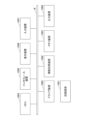
- FIG. 1 shows an example of the overall configuration of a wireless communication system in this embodiment.
- this wireless communication system includes one or more terminal devices 20, one or more relay station devices 10, one or more base station devices 30, and a control device 40.
- control device 40 is provided on the upper NW (network) 50.
- NW network
- the control device 40 may be provided anywhere.
- the function of the control device 40 may be provided in any one of the terminal 20, the relay station device 10, and the base station device 30.
- any device having the function of the control device 40 may be referred to as a "control device.”
- the terminal device 20 is a device that can communicate wirelessly with the relay station device 10 or the base station device 30, and includes a single wireless system interface or a plurality of different wireless system interfaces.
- the plurality of terminal devices 20 there may be a mixture of terminal devices that connect to the base station device 30 via the relay station device 10 and terminal devices 20 that connect to the base station device 30 directly.
- the relay station device 10 relays communication between the terminal device 20 and the base station device 30.
- Relay station device 10 includes interfaces for a plurality of different wireless systems.
- the relay station device 10 may also be called an accommodation distribution relay station device.
- the base station device 30 transmits a signal received wirelessly from the terminal device 20 side to the upper NW 50, and transmits a signal received from the upper NW 50 wirelessly to the terminal device 20 side. It is assumed that a plurality of different wireless systems coexist in the plurality of base station devices 10. However, the plurality of base station devices 10 may be only a single wireless system.
- Wireless system may also be referred to as system, wireless communication method, wireless method, communication method, RAT (radio access technology), etc.
- wireless systems include 3G, 4G, 5G, 6G, wireless LAN, WiMAX, and the like.
- a “wireless system” may be referred to as a "system.”
- the upper NW 50 may be a core network of a mobile network (eg, 5G), the Internet, or a network other than these.
- a mobile network eg, 5G
- the Internet e.g., the Internet
- the control device 40 performs distribution control (determination of transmission method), which will be described later. Control device 40 notifies relay station device 10 of the determined transmission method. Further, instead of the control device 40 determining the transmission method, the relay station device 10 may determine the transmission method. Further, communication of a terminal device whose transmission method is determined by the control device 40 and communication of a terminal device whose transmission method is determined by the relay station device 10 may coexist.
- the base station device 30 and the control device 40 are connected by wire. However, the base station device 30 and the control device 40 may be connected wirelessly. When using a wireless connection, IAB (Integrated Access Backhaul), WiGig, etc. may be used.
- IAB Integrated Access Backhaul
- WiGig WiGig
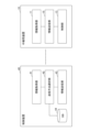
- FIG. 2 shows the configuration of each device in the wireless communication system described above.
- FIG. 2 shows an example 1 in which the relay station device 10 determines the transmission method.
- FIG. 3 shows the functional configuration of the relay station device 10 of Example 1 other than the wireless transmitting/receiving section.
- the relay station device 10 has a wireless transmitter/receiver 16 for each system. Further, as shown in FIG. 3, the relay station device 10 includes an information acquisition section 11, a transmission method selection section 12, a control section 13, and a DB (database) 14.
- the "wireless transmitting/receiving unit" may also be referred to as an "interface.”
- the terminal device 20 has a wireless transmitter/receiver 21 for each system.
- the base station device 30 has a wireless transmitter/receiver 31 for each system.
- the information acquisition unit 11 of the relay station device 10 acquires the quality, the capability information (Capability) of the terminal device 20, the priority of the terminal device 20 (or APP), etc., and the transmission method selection unit 12 acquires these information.
- the transmission method is determined using this information.
- the control unit 13 establishes a communication path using the determined transmission method.
- FIG. 2 shows an example where system A is selected as the communication method between the terminal device 20 and the relay station device 10, and system B is selected as the communication method between the relay device 10 and the base station device 30. It shows.
- FIG. 4 shows a second example in which the control device 40 determines the transmission method.
- FIG. 5 shows the functional configuration other than the wireless transmitting/receiving unit and the functional configuration of the control device 40 in the relay station device 10 of Example 2.
- the relay station device 10 has a wireless transmitter/receiver 16 for each system.
- the relay station device 10 includes an information acquisition section 11, an information transmission section 15, and a control section 13.
- the control device 40 includes an information acquisition section 41, a transmission method selection section 42, an information transmission section 43, and a DB (database) 44.
- the terminal device 20 has a wireless transmitter/receiver 21 for each system.
- the base station device 30 has a wireless transmitter/receiver 31 for each system.
- Example 2 the information acquisition unit 11 of the relay station device 10 acquires the same information as in Example 1, and the information transmission unit 15 transmits the information to the control device 40.
- the transmission method selection unit 42 of the control device 40 uses the information to determine the transmission method, and the information transmission unit 43 transmits the determination result to the relay station device 10.
- the control unit 13 of the relay station device 10 establishes a communication path using the determined transmission method.
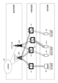
- FIG. 6 is a diagram showing an image of the operation.
- the relay station device 10-1 which can establish communication with the terminal device 20-1, A transmission method (which may also be referred to as a data transmission method) for 1 is determined (selected).
- the transmission method here refers to which system is used and what method is used for communication path 1 between "relay station device - base station device” and communication path 2 between "terminal device - relay station device”. This is a method (information) that indicates whether the transmission is to be performed. Furthermore, in this embodiment, the transmission method determined for each of communication path 1 and communication path 2 may be applied to bidirectional communication or may be applied to only unidirectional communication. good. When applied to communication in only one direction, another transmission method may be applied for communication in another direction.
- Example 1 an operation example of the configuration of Example 1 (FIGS. 2 and 3) will be described as Operation Example 1, and an operation example of the configuration of Example 2 (FIGS. 4 and 5) will be described as Operation Example 2.
- relay station device 10 when the relay station device 10 relays a system that requires synchronization, such as 5G cellular, the relay station device 10 needs to be synchronized with the base station device 30 and the terminal device 20 in advance. Therefore, when assuming a system that assumes synchronization, the following operation example assumes that relay station device 10 is synchronized with base station device 30 and terminal device 20 in advance.
- a synchronization signal for synchronization between the relay station device 10 and the base station device 30, for example, similar to the initial access procedure of 5G New Radio, a synchronization signal (PSS (Primary Synchronization Signal)/ It is best to match the SSS (Secondary Synchronization Signal).
- PSS Primary Synchronization Signal
- the synchronization signal may be periodically transmitted from the base station device 30, and the clock of the relay station device 10 may be updated each time it is received.
- the synchronization between the relay station device 10 and the terminal device 20 is such that each synchronizes with the synchronization signal of the base station device 30, or the relay station device 10 periodically transmits a synchronization signal and the terminal device 20 synchronizes with the synchronization signal of the base station device 30. This may be realized by updating the clock accordingly.
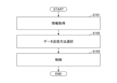
- Operation example 1 will be explained along the steps of the flowchart in FIG. Below, an operation for establishing communication with respect to a certain terminal device 20 (target terminal device 20) will be explained.
- the information acquisition unit 11 of the relay station device 10 determines the connection quality (which may also be referred to as wireless quality, reception quality, etc.) between the target terminal device 20 and the relay station device 10, and the relay station device 10.
- the connection quality between the base station device 30 and the relay station device 10 with which communication can be established is acquired.
- the connection quality may be reception quality/reception power on the relay station device 10 side, or reception quality/reception power on the terminal device 20 side/base station device 30 side. If one device supports multiple systems, obtain the connection quality for each system.
- SS-RSRP Synchronization Signal reference signal received power
- SINR Signal-to-interference-plus-noise ratio
- RSSI Received Signal Strength Indicator
- SS-RSRP is a linear average power value of a resource element that carries a secondary synchronization signal.
- the information acquisition unit 11 also obtains a maximum throughput from a correspondence table (reception power and maximum throughput correspondence table) acquired in advance for each wireless system and communication path (relay station device - terminal device, relay station - base station, etc.).
- the predicted communication quality (throughput) may be calculated by dividing this value proportionally by the number of connected devices.
- the information acquisition unit 11 transmits 150 Mbps to the “relay station device 10A- The predicted communication quality (throughput) in the terminal device 20A.
- this predicted throughput may be the throughput from the relay station device 10A to the terminal device 20A, the throughput from the terminal device 20 to the relay station device 10A, or the throughput in both directions. You can.
- the information acquisition unit 11 may use a machine learning model to learn the output throughput in advance using received power, the number of connected devices, etc. as input, and predict the throughput using the learned model.
- connection quality, reception quality, reception power, communication quality, etc. may be collectively referred to as "quality.”
- connection quality with the base station device 30 “base station device 30-1, base station device 30-2” for each of system A and system B as devices that can establish communication with the relay station device 10. If there is a For each, the connection quality (or communication quality) is acquired, and for system B (“between the relay station device 10 and the base station device 30-1”, “between the relay station device 10 and the base station device 30-2”) The connection quality (or communication quality) is obtained for each of the periods (between 1 and 2).
- the information acquisition unit 11 attempts to connect to the terminal device 20 using a wireless system compatible with the relay station device 10, thereby grasping the terminal capability (systems supported by the terminal device 20, etc.).
- Terminal Capability may include priority.
- the transmission method selection unit 12 of the relay station device 10 selects a data transmission method between the relay station device 10 and the terminal device 20, based on the connection quality (or calculated communication quality) acquired in S101, and A data transmission method between relay station device 10 and base station device 30 is selected (determined). Details of the selection method will be described later.
- the control unit 13 of the relay station device 10 establishes a communication path between the relay station device 10 and the terminal device 20 according to the selection result in S102, and establishes a communication path between the relay station device 10 and the base station device 30. Communication paths are established and communication using these communication paths is started.
- the data transmission method selection process executed by the transmission method selection unit 12 will be described.
- the transmission method selection unit 12 selects among redundant transmission, divided transmission, and selective transmission based on the quality of the communication path, the terminal priority, the priority of the APP (application) being used by the terminal device 20, the request delay time, etc. Select one of these as the data transmission method.
- using redundant transmission, divided transmission, and selective transmission are examples, and transmission methods other than these may also be used.
- Redundant transmission is a transmission method that transmits redundant signals over multiple communication paths. Although this transmission method uses a large amount of radio resources, it increases the possibility that the connection can be maintained even in the case of sudden shielding, and can be expected to improve reliability.
- Divided transmission is a transmission method in which a signal is divided and transmitted over multiple communication paths. With this transmission method, it is possible to avoid loss of all data due to sudden shielding, etc., and to achieve transmission similar to redundant transmission.
- Selective transmission is a transmission method that selects a single communication path and transmits a signal. With this transmission method, communication quality can be selected to some extent depending on the selected communication path.
- the specific selection procedure is as follows.
- the transmission method selection section 12 selects a communication path that satisfies a predetermined quality among the communication paths for each system as a communication path selection candidate.
- a communication path that satisfies a predetermined quality is, for example, if the quality is SS-RSRP and the predetermined quality value is Q, then the communication path to be judged has SS-RSRP equal to or higher than Q. It is a certain thing.
- the terminal device 20, the relay station device 10, and the base station device 30 can each use systems A, B, and C, and that the following quality of each communication path is obtained.
- one base station device 30 may be able to use systems A, B, and C, or multiple base station devices 30 may be able to use systems A, B, and C. (For example, when base station devices 30A, 30B, and 30C are present).
- Communication path 1A "Relay station device 10 - base station device 30" of system A Communication path 1B: “Relay station device 10 - base station device 30" of system B Communication path 1C: “Relay station device 10 - base station device 30" of system C Communication path 2A: “Relay station device 10 - terminal device 20" of system A Communication path 2B: “Relay station device 10 - terminal device 20" of system B Communication path 2C: “Relay station device 10 - terminal device 20" of system C Among the above, when each of the communication path 1A, communication path 1B, communication path 2A, and communication path 2C satisfies the quality standard (the other paths do not satisfy the quality standard), the transmission method selection unit 12 selects the communication path 1A, Communication path 1B, communication path 2A, and communication path 2C are selected as communication path candidates.
- one system may select multiple communication paths as candidates.
- a redundant configuration using a plurality of communication paths in one system may be included in the transmission method options described below.
- the transmission method selection unit 12 transmits data to the terminal device 20 according to the priority of the terminal device 20 or the priority of the application used by the terminal device 20. Select (determine) the transmission method.
- the specific processing is as follows. "The priority of the terminal device 20 or the priority of the application used by the terminal device 20" is described as “terminal (APP) priority.” “Terminal priority” may also include the meaning of the priority of the application used by the terminal device 20.
- data transmission methods to be used preferentially are prepared as a table (a table that associates priorities with data transmission methods) for each terminal (application) priority, and the table is stored in the DB 14.
- the transmission method selection unit 12 refers to this table and determines the data transmission method.
- FIG. 8 shows an example of the table.
- the "data transmission method” here refers to which system is used and which transmission method is used.
- the numbers in the table indicate usage priority. For example, when the terminal (APP) priority is 1, “System A + System B redundant transmission” whose priority is 1 is used with the highest priority. If “System A + System B redundant transmission” cannot be used, but “System A + System C redundant transmission” whose priority is 2 can be used, “System A + System C redundant transmission” is used.
- the transmission method selection unit 12 transmits data to the target terminal device 20 by referring to the table in FIG. 8 based on the terminal (APP) priority of the target terminal device 20 and the communication path selection candidates selected in S1. Choose a method.
- Communication path 1A "Relay station device 10 - base station device 30" of system A Communication path 1B: “Relay station device 10 - base station device 30" of system B Communication path 2A: “Relay station device 10 - terminal device 20" of system A Communication path 2C: “Relay station device 10 - terminal device 20" of system C
- the data transmission method selected for each of the terminal (APP) priorities 1 to 4 of the target terminal device 20 will be described below. Note that the transmission method selection unit 12 grasps the usage status of each transmission method, and if selected, selects a transmission method with one lower priority among the available transmission methods for transmission methods that exceed the capacity upper limit value. You may.
- Terminal (APP) priority 1 The transmission method selection unit 12 selects "system A + system B redundant transmission” for the communication path 1 of "relay station device 10 - base station device 30", and selects "system A + system B redundant transmission” for the communication path of "relay station device 10 - terminal device 20". For 2, select "System A + System C redundant transmission”.
- Terminal priority 2 The transmission method selection unit 12 selects "system A + system B divided transmission” for the communication path 1 of "relay station device 10 - base station device 30", and selects "system A + system B divided transmission” for the communication path of "relay station device 10 - terminal device 20". For 2, select "System A selection transmission”.
- Terminal priority 3 The transmission method selection unit 12 selects "system B selection transmission” for communication path 1 of "relay station device 10 - base station device 30", and selects "system B selection transmission” for communication path 2 of "relay station device 10 - terminal device 20". select "System C selection transmission”.
- Terminal priority 4 The transmission method selection unit 12 selects "system B selection transmission” for communication path 1 of "relay station device 10 - base station device 30", and selects "system B selection transmission” for communication path 2 of "relay station device 10 - terminal device 20". select "System C selection transmission”.
- operation example 2 which is an operation example in the configuration of example 2 (FIGS. 4 and 5), will be described. Since the basic process flow is the same as that of the first operational example, the second operational example will also be described with reference to the flowchart of FIG. 7 in the same way as the first operational example. Furthermore, for the same processes as those in operation example 1, explanations will be omitted or only brief explanations will be provided.
- the information acquisition unit 11 of the relay station device 10 acquires the connection quality (or communication quality), terminal capability, etc. of each communication path, as in the process in the first operation example.
- the information transmitter 15 of the relay station device 10 transmits the information acquired by the information acquirer 11 to the control device 40 .
- the information acquisition unit 41 of the control device 40 acquires the information.
- the transmission method selection unit 42 of the control device 40 selects a data transmission method between the relay station device 10 and the terminal device 20, and a relay method based on the connection quality (or the calculated communication quality) obtained in S101.
- a data transmission method between the station device 10 and the base station device 30 is selected.
- the control device 40 has a DB 44 that stores the table shown in FIG. 8, and the transmission method selection unit 42 of the control device 40 refers to the DB 44 to select a data transmission method.
- the process for selecting the data transmission method is the same as in operation example 1.
- the information transmission unit 43 of the control device 40 transmits the data transmission method selection result by the transmission method selection unit 42 to the relay station device 10 that is the information transmission source.
- the information acquisition unit 11 of the relay station device 10 acquires the data transmission method selection result.
- S103 the control unit 13 of the relay station device 10 establishes a communication path between the relay station device 10 and the terminal device 20 according to the selection result in S102, and connects the relay station device 10 and the base station. Communication paths are established with the device 30, and communication using these communication paths is started.
- the terminal device 20, the relay station device 10, the base station device 30, and the control device 40 can all be realized, for example, by causing a computer to execute a program.
- This computer may be a physical computer or a virtual machine on the cloud.
- terminal device 20, relay station device 10, base station device 30, and control device 40 will be collectively referred to as "device.”
- the device can be realized by using hardware resources such as a CPU and memory built into a computer to execute a program corresponding to the processing performed by the device.
- the above program can be recorded on a computer-readable recording medium (such as a portable memory) and can be stored or distributed. It is also possible to provide the above program through a network such as the Internet or e-mail.
- FIG. 9 is a diagram showing an example of the hardware configuration of the computer.
- the computer in FIG. 9 includes a drive device 1000, an auxiliary storage device 1002, a memory device 1003, a CPU 1004, an interface device 1005, a display device 1006, an input device 1007, an output device 1008, etc., which are interconnected by a bus BS.
- a program that realizes processing on the computer is provided, for example, on a recording medium 1001 such as a CD-ROM or a memory card.
- a recording medium 1001 such as a CD-ROM or a memory card.
- the program is installed from the recording medium 1001 to the auxiliary storage device 1002 via the drive device 1000.
- the program does not necessarily need to be installed from the recording medium 1001, and may be downloaded from another computer via a network.
- the auxiliary storage device 1002 stores installed programs as well as necessary files, data, and the like.
- the memory device 1003 reads and stores the program from the auxiliary storage device 1002 when there is an instruction to start the program.
- the CPU 1004 implements functions related to the device according to programs stored in the memory device 1003.
- the interface device 1005 is used as an interface for connecting to a network or the like.
- a display device 1006 displays a GUI (Graphical User Interface) and the like based on a program.
- the input device 1007 is composed of a keyboard, a mouse, buttons, a touch panel, or the like, and is used to input various operation instructions.
- An output device 1008 outputs the calculation result. Note that any or all of the display device 1006, input device 1007, and output device 1008 may not be provided.
- the terminal devices can communicate using an appropriate wireless system according to their capabilities without performing distribution control on the terminal devices.
- it is possible to perform system-wide radio resource control according to the functions of the terminal device without directly controlling the terminal device. This makes it possible to efficiently and economically operate a high-quality network that utilizes multiple wireless systems.
- the order of priority transmission methods used is switched or reversed between high priority terminals (APP) and low priority terminals (APP).
- APP high priority terminals
- APP low priority terminals
- the data transmission method is selected so that less resources are used when the priority is low than when the priority is high.
- a wireless communication system comprising a relay station device capable of relaying wireless communication between one or more base station devices and a terminal device using a plurality of systems, and a control device, The relay station device acquires the quality between the terminal device and each base station device that the relay station device relays for each system, and notifies the control device of the acquired quality. death, The control device establishes a communication path between each base station device and the relay station device and a communication path between the relay station device and the terminal device based on the quality and the priority of the terminal device.
- a wireless communication system that determines a data transmission method for each communication path and notifies the relay station device of the determined data transmission method.
- the wireless communication system according to appendix 1 wherein the data transmission method is redundant transmission, divided transmission, or selective transmission.
- the wireless communication system according to appendix 1 or 2 wherein the control device determines the data transmission method for each communication path by referring to a table that describes the relationship between priorities and data transmission methods.
- the control device When the priority of the terminal device is a first priority, the control device transmits a resource smaller than the amount of resources used in a data transmission method determined for a second priority higher than the first priority.
- the wireless communication system according to any one of Supplementary Notes 1 to 3, wherein a data transmission method using the amount of data is determined.
- the control device in a wireless communication system comprising a relay station device capable of relaying wireless communication between one or more base station devices and a terminal device using a plurality of systems, and a control device, memory and at least one processor connected to the memory; including;
- the processor includes: For the terminal device and each base station device that the relay station device performs relaying, acquire the quality of each system between the relay station device and the relay station device, Based on the quality and the priority of the terminal device, data for each communication path between each base station device and the relay station device and the communication path between the relay station device and the terminal device.
- a control device that notifies the relay station device of the determined data transmission method.
- a relay station device capable of relaying wireless communication between one or more base station devices and a terminal device using a plurality of systems, memory and at least one processor connected to the memory; including; The processor includes: For each base station device and the terminal device to which the relay station device performs relay, the quality between the terminal device and the relay station device is acquired for each system, Based on the quality and the priority of the terminal device, data for each communication path between each base station device and the relay station device and the communication path between the relay station device and the terminal device.
- a relay station device comprising: determining a transmission method.
- a data transmission method determination method in a wireless communication system comprising a relay station device capable of relaying wireless communication between one or more base station devices and a terminal device using a plurality of systems, and a control device, the method comprising: The relay station device acquires the quality between the terminal device and each base station device that the relay station device relays for each system, and notifies the control device of the acquired quality. death, The control device establishes a communication path between each base station device and the relay station device and a communication path between the relay station device and the terminal device based on the quality and the priority of the terminal device.
- a method for determining a data transmission method comprising: determining a data transmission method for each communication path, and notifying the relay station device of the determined data transmission method.
Landscapes
- Engineering & Computer Science (AREA)
- Computer Networks & Wireless Communication (AREA)
- Signal Processing (AREA)
- Mobile Radio Communication Systems (AREA)
- Radio Relay Systems (AREA)
Abstract
Description
前記中継局装置は、前記中継局装置が中継を行う前記端末装置と各基地局装置について、前記中継局装置との間の品質をシステムごとに取得し、取得した前記品質を前記制御装置に通知し、
前記制御装置は、前記品質と、前記端末装置の優先度とに基づいて、各基地局装置と前記中継局装置との間の通信パス、及び、前記中継局装置と前記端末装置との間の通信パスそれぞれのデータ送信方法を決定し、決定したデータ送信方法を前記中継局装置に通知する
無線通信システムが提供される。
図1に、本実施の形態における無線通信システムの全体構成例を示す。図1に示すように、本無線通信システムは、1つ又は複数の端末装置20、1つ又は複数の中継局装置10、1つ又は複数の基地局装置30、及び制御装置40を有する。
上述した無線通信システムにおける各装置の構成を示したものを図2に示す。図2は、中継局装置10が送信方法の決定を行う例1を示している。また、図3は、例1の中継局装置10における、無線送受信部以外の機能構成を示している。
図4は、制御装置40が送信方法の決定を行う例2を示している。また、図5は、例2の中継局装置10における、無線送受信部以外の機能構成、及び制御装置40の機能構成を示している。
以下、上記のような構成を備える無線通信システムの動作例を説明する。図6は動作のイメージを示す図である。例えば、システムAとBの両方に対応する端末装置20-1が、通信要求を発出したことを契機として、端末装置20-1と通信確立可能な中継局装置10-1が、端末装置20-1に対する送信方法(データ送信方法と称してもよい)を決定(選択)する。
動作例1を図7のフローチャートの手順に沿って説明する。以下では、ある端末装置20(対象の端末装置20)についての通信確立のための動作を説明する。
S101において、中継局装置10の情報取得部11は、対象の端末装置20と中継局装置10との間の接続品質(無線品質、受信品質、等と呼んでもよい)、及び、中継局装置10との通信の確立が可能な基地局装置30と中継局装置10との間の接続品質を取得する。接続品質は、中継局装置10側の受信品質/受信電力であってもよいし、端末装置20側/基地局装置30側の受信品質/受信電力であってもよい。1装置で複数システムに対応している場合、システムごとの接続品質を取得する。
S102において、中継局装置10の送信方法選択部12は、S101において取得した接続品質(又は算出した通信品質)を基に、中継局装置10と端末装置20との間のデータ送信方法、及び、中継局装置10と基地局装置30との間のデータ送信方法を選択(決定)する。選択方法の詳細は後述する。
S103において、中継局装置10の制御部13は、S102における選択結果に従って、中継局装置10と端末装置20との間の通信パスを確立し、中継局装置10と基地局装置30との間の通信パスを確立し、これらの通信パスを用いた通信を開始させる。
送信方法選択部12が実行するデータ送信方法の選択処理について説明する。送信方法選択部12は、通信パスの品質、端末優先度、端末装置20が使用中のAPP(アプリケーション)の優先度、要求遅延時間等を基に、冗長送信、分割送信、及び選択送信のうちのいずれかをデータ送信方法として選択する。ただし、冗長送信、分割送信、及び選択送信を使用することは例であり、これら以外の送信方法を使用してもよい。
まず、送信方法選択部12は、情報取得部11により取得した品質に基づき、システムごとの通信パスの内、予め定めた品質を満たす通信パスを、通信パス選択候補として選定する。予め定めた品質(品質基準)を満たす通信パスとは、例えば、品質がSS-RSRPであり、予め定めた品質の値がQである場合、判断対象の通信パスのSS-RSRPがQ以上であることである。
通信パス1B:システムBの「中継局装置10-基地局装置30」
通信パス1C:システムCの「中継局装置10-基地局装置30」
通信パス2A:システムAの「中継局装置10-端末装置20」
通信パス2B:システムBの「中継局装置10-端末装置20」
通信パス2C:システムCの「中継局装置10-端末装置20」
上記のうち、通信パス1A、通信パス1B、通信パス2A、通信パス2Cのそれぞれが品質基準を満たす場合(他のパスは品質基準を満たさない)、送信方法選択部12は、通信パス1A、通信パス1B、通信パス2A、通信パス2Cを通信パス候補として選択する。
次に、送信方法選択部12は、S1で選択した通信パス候補に基づいて、端末装置20の優先度、又は、端末装置20が使用するアプリケーションの優先度に応じて、その端末装置20に対するデータ送信方法を選択(決定)する。具体的な処理は下記のとおりである。「端末装置20の優先度、又は、端末装置20が使用するアプリケーションの優先度」を「端末(APP)優先度」と記述する。「端末優先度」に、端末装置20が使用するアプリケーションの優先度の意味も含まれることとしてもよい。
通信パス1B:システムBの「中継局装置10-基地局装置30」
通信パス2A:システムAの「中継局装置10-端末装置20」
通信パス2C:システムCの「中継局装置10-端末装置20」
対象の端末装置20の端末(APP)優先度1~4のそれぞれの場合について選択されるデータ送信方法について、以下に記載する。なお、送信方法選択部12は、各送信方法の使用状況を把握し、選択すると容量上限値を超える送信方法に関しては、使用可能な送信方法のうち、一つ下位の優先度の送信方法を選択してもよい。
送信方法選択部12は、「中継局装置10-基地局装置30」の通信パス1については、「システムA+システムB冗長送信」を選択し、「中継局装置10-端末装置20」の通信パス2については「システムA+システムC冗長送信」を選択する。
送信方法選択部12は、「中継局装置10-基地局装置30」の通信パス1については、「システムA+システムB分割送信」を選択し、「中継局装置10-端末装置20」の通信パス2については「システムA選択送信」を選択する。
送信方法選択部12は、「中継局装置10-基地局装置30」の通信パス1については、「システムB選択送信」を選択し、「中継局装置10-端末装置20」の通信パス2については「システムC選択送信」を選択する。
送信方法選択部12は、「中継局装置10-基地局装置30」の通信パス1については、「システムB選択送信」を選択し、「中継局装置10-端末装置20」の通信パス2については「システムC選択送信」を選択する。
次に、例2の構成(図4,図5)における動作例である動作例2を説明する。基本的な処理の流れは動作例1と同じであるので、動作例2でも動作例1と同じく図7のフローチャートを参照して説明する。また、動作例1での処理と同じ処理については、説明を省略するか、簡単な説明のみとする。
S101において、中継局装置10の情報取得部11は、動作例1での処理と同じく、各通信パスの接続品質(又は通信品質)、端末capability等を取得する。中継局装置10の情報送信部15は、情報取得部11により取得された情報を、制御装置40に送信する。制御装置40の情報取得部41が、当該情報を取得する。
S102において、制御装置40の送信方法選択部42は、S101において取得した接続品質(又は算出した通信品質)を基に、中継局装置10と端末装置20との間のデータ送信方法、及び、中継局装置10と基地局装置30との間のデータ送信方法を選択する。制御装置40は、図8のテーブルを格納したDB44を有しており、制御装置40の送信方法選択部42は、DB44を参照して、データ送信方法を選択する。データ送信方法の選択の処理については、動作例1と同じである。
動作例1と同じく、S103において、中継局装置10の制御部13は、S102における選択結果に従って、中継局装置10と端末装置20との間の通信パスを確立し、中継局装置10と基地局装置30との間の通信パスを確立し、これらの通信パスを用いた通信を開始させる。
端末装置20、中継局装置10、基地局装置30、制御装置40はいずれも、例えば、コンピュータにプログラムを実行させることにより実現できる。このコンピュータは、物理的なコンピュータであってもよいし、クラウド上の仮想マシンであってもよい。以下、「端末装置20、中継局装置10、基地局装置30、制御装置40」を総称して「装置」と呼ぶ。
以上説明したとおり、本実施の形態に係る技術では、端末装置に対する振り分け制御を行うことなく、端末装置が、能力に応じた適切な無線システムを利用して通信を行うことができる。つまり、端末装置の直接的な制御を行うことなく、端末装置の機能に応じたシステム横断的な無線リソース制御を行うことができる。これにより、複数の無線システムを活用した高品質ネットワークの効率的・経済的運用が可能となる。
本明細書には、少なくとも下記各項の無線通信システム、制御装置、中継局装置、及びデータ送信方法決定方法が開示されている。
(付記項1)
1以上の基地局装置と端末装置との無線通信を複数のシステムを用いて中継することが可能な中継局装置と、制御装置とを備える無線通信システムであって、
前記中継局装置は、前記中継局装置が中継を行う前記端末装置と各基地局装置について、前記中継局装置との間の品質をシステムごとに取得し、取得した前記品質を前記制御装置に通知し、
前記制御装置は、前記品質と、前記端末装置の優先度とに基づいて、各基地局装置と前記中継局装置との間の通信パス、及び、前記中継局装置と前記端末装置との間の通信パスそれぞれのデータ送信方法を決定し、決定したデータ送信方法を前記中継局装置に通知する
無線通信システム。
(付記項2)
前記データ送信方法は、冗長送信、分割送信、又は選択送信である
付記項1に記載の無線通信システム。
(付記項3)
前記制御装置は、優先度とデータ送信方法との関係を記載したテーブルを参照することにより、各通信パスのデータ送信方法を決定する
付記項1又は2に記載の無線通信システム。
(付記項4)
前記制御装置は、前記端末装置の優先度が第1優先度である場合に、当該第1優先度よりも高い第2優先度に対して決定するデータ送信方法で使用するリソース量よりも少ないリソース量を使用するデータ送信方法を決定する
付記項1ないし3のうちいずれか1項に記載の無線通信システム。
(付記項5)
1以上の基地局装置と端末装置との無線通信を複数のシステムを用いて中継することが可能な中継局装置と、制御装置とを備える無線通信システムにおける前記制御装置であって、
メモリと、
前記メモリに接続された少なくとも1つのプロセッサと、
を含み、
前記プロセッサは、
前記中継局装置が中継を行う前記端末装置と各基地局装置について、前記中継局装置との間のシステムごとの品質を前記中継局装置から取得し、
前記品質と、前記端末装置の優先度とに基づいて、各基地局装置と前記中継局装置との間の通信パス、及び、前記中継局装置と前記端末装置との間の通信パスそれぞれのデータ送信方法を決定し、
決定したデータ送信方法を前記中継局装置に通知する
制御装置。
(付記項6)
1以上の基地局装置と端末装置との無線通信を複数のシステムを用いて中継することが可能な中継局装置であって、
メモリと、
前記メモリに接続された少なくとも1つのプロセッサと、
を含み、
前記プロセッサは、
前記中継局装置が中継を行う前記端末装置と各基地局装置について、前記中継局装置との間の品質をシステムごとに取得し、
前記品質と、前記端末装置の優先度とに基づいて、各基地局装置と前記中継局装置との間の通信パス、及び、前記中継局装置と前記端末装置との間の通信パスそれぞれのデータ送信方法を決定する
を備える中継局装置。
(付記項7)
1以上の基地局装置と端末装置との無線通信を複数のシステムを用いて中継することが可能な中継局装置と、制御装置とを備える無線通信システムにおけるデータ送信方法決定方法であって、
前記中継局装置は、前記中継局装置が中継を行う前記端末装置と各基地局装置について、前記中継局装置との間の品質をシステムごとに取得し、取得した前記品質を前記制御装置に通知し、
前記制御装置は、前記品質と、前記端末装置の優先度とに基づいて、各基地局装置と前記中継局装置との間の通信パス、及び、前記中継局装置と前記端末装置との間の通信パスそれぞれのデータ送信方法を決定し、決定したデータ送信方法を前記中継局装置に通知する
データ送信方法決定方法。
11 情報取得部
12 送信方法選択部
13 制御部
14 DB
15 情報送信部
16 無線送受信部
20 端末装置
21 無線送受信部
30 基地局装置
31 無線送受信部
40 制御装置
41 情報取得部
42 送信方法選択部
43 情報送信部
44 DB
50 上位NW
1000 ドライブ装置
1001 記録媒体
1002 補助記憶装置
1003 メモリ装置
1004 CPU
1005 インタフェース装置
1006 表示装置
1007 入力装置
1008 出力装置
Claims (7)
- 1以上の基地局装置と端末装置との無線通信を複数のシステムを用いて中継することが可能な中継局装置と、制御装置とを備える無線通信システムであって、
前記中継局装置は、前記中継局装置が中継を行う前記端末装置と各基地局装置について、前記中継局装置との間の品質をシステムごとに取得し、取得した前記品質を前記制御装置に通知し、
前記制御装置は、前記品質と、前記端末装置の優先度とに基づいて、各基地局装置と前記中継局装置との間の通信パス、及び、前記中継局装置と前記端末装置との間の通信パスそれぞれのデータ送信方法を決定し、決定したデータ送信方法を前記中継局装置に通知する
無線通信システム。 - 前記データ送信方法は、冗長送信、分割送信、又は選択送信である
請求項1に記載の無線通信システム。 - 前記制御装置は、優先度とデータ送信方法との関係を記載したテーブルを参照することにより、各通信パスのデータ送信方法を決定する
請求項1に記載の無線通信システム。 - 前記制御装置は、前記端末装置の優先度が第1優先度である場合に、当該第1優先度よりも高い第2優先度に対して決定するデータ送信方法で使用するリソース量よりも少ないリソース量を使用するデータ送信方法を決定する
請求項1に記載の無線通信システム。 - 1以上の基地局装置と端末装置との無線通信を複数のシステムを用いて中継することが可能な中継局装置と、制御装置とを備える無線通信システムにおける前記制御装置であって、
前記中継局装置が中継を行う前記端末装置と各基地局装置について、前記中継局装置との間のシステムごとの品質を前記中継局装置から取得する情報取得部と、
前記品質と、前記端末装置の優先度とに基づいて、各基地局装置と前記中継局装置との間の通信パス、及び、前記中継局装置と前記端末装置との間の通信パスそれぞれのデータ送信方法を決定する送信方法選択部と、
決定したデータ送信方法を前記中継局装置に通知する情報送信部と
を備える制御装置。 - 1以上の基地局装置と端末装置との無線通信を複数のシステムを用いて中継することが可能な中継局装置であって、
前記中継局装置が中継を行う前記端末装置と各基地局装置について、前記中継局装置との間の品質をシステムごとに取得する情報取得部と、
前記品質と、前記端末装置の優先度とに基づいて、各基地局装置と前記中継局装置との間の通信パス、及び、前記中継局装置と前記端末装置との間の通信パスそれぞれのデータ送信方法を決定する送信方法選択部と
を備える中継局装置。 - 1以上の基地局装置と端末装置との無線通信を複数のシステムを用いて中継することが可能な中継局装置と、制御装置とを備える無線通信システムにおけるデータ送信方法決定方法であって、
前記中継局装置は、前記中継局装置が中継を行う前記端末装置と各基地局装置について、前記中継局装置との間の品質をシステムごとに取得し、取得した前記品質を前記制御装置に通知し、
前記制御装置は、前記品質と、前記端末装置の優先度とに基づいて、各基地局装置と前記中継局装置との間の通信パス、及び、前記中継局装置と前記端末装置との間の通信パスそれぞれのデータ送信方法を決定し、決定したデータ送信方法を前記中継局装置に通知する
データ送信方法決定方法。
Priority Applications (3)
| Application Number | Priority Date | Filing Date | Title |
|---|---|---|---|
| US18/880,839 US20260006529A1 (en) | 2022-07-07 | 2022-07-07 | Wireless communication system, control apparatus, relay station apparatus, and data transmission method determination method |
| PCT/JP2022/027031 WO2024009482A1 (ja) | 2022-07-07 | 2022-07-07 | 無線通信システム、制御装置、中継局装置、及びデータ送信方法決定方法 |
| JP2024531868A JP7758196B2 (ja) | 2022-07-07 | 2022-07-07 | 無線通信システム、制御装置、中継局装置、及びデータ送信方法決定方法 |
Applications Claiming Priority (1)
| Application Number | Priority Date | Filing Date | Title |
|---|---|---|---|
| PCT/JP2022/027031 WO2024009482A1 (ja) | 2022-07-07 | 2022-07-07 | 無線通信システム、制御装置、中継局装置、及びデータ送信方法決定方法 |
Publications (1)
| Publication Number | Publication Date |
|---|---|
| WO2024009482A1 true WO2024009482A1 (ja) | 2024-01-11 |
Family
ID=89453123
Family Applications (1)
| Application Number | Title | Priority Date | Filing Date |
|---|---|---|---|
| PCT/JP2022/027031 Ceased WO2024009482A1 (ja) | 2022-07-07 | 2022-07-07 | 無線通信システム、制御装置、中継局装置、及びデータ送信方法決定方法 |
Country Status (3)
| Country | Link |
|---|---|
| US (1) | US20260006529A1 (ja) |
| JP (1) | JP7758196B2 (ja) |
| WO (1) | WO2024009482A1 (ja) |
Citations (3)
| Publication number | Priority date | Publication date | Assignee | Title |
|---|---|---|---|---|
| JP2012147122A (ja) * | 2011-01-07 | 2012-08-02 | Ntt Docomo Inc | 通信端末および通信制御方法 |
| JP2019071505A (ja) * | 2016-03-02 | 2019-05-09 | シャープ株式会社 | 制御局装置、通信方法および通信システム |
| JP2020010283A (ja) * | 2018-07-12 | 2020-01-16 | 日本電信電話株式会社 | 無線通信システム、制御方法、制御装置及び制御プログラム |
Family Cites Families (2)
| Publication number | Priority date | Publication date | Assignee | Title |
|---|---|---|---|---|
| JP5417214B2 (ja) * | 2010-02-12 | 2014-02-12 | 株式会社Kddi研究所 | 移動通信システム |
| WO2015072174A1 (ja) * | 2013-11-18 | 2015-05-21 | 日本電気株式会社 | 送信装置、制御方法、及びプログラム |
-
2022
- 2022-07-07 US US18/880,839 patent/US20260006529A1/en active Pending
- 2022-07-07 WO PCT/JP2022/027031 patent/WO2024009482A1/ja not_active Ceased
- 2022-07-07 JP JP2024531868A patent/JP7758196B2/ja active Active
Patent Citations (3)
| Publication number | Priority date | Publication date | Assignee | Title |
|---|---|---|---|---|
| JP2012147122A (ja) * | 2011-01-07 | 2012-08-02 | Ntt Docomo Inc | 通信端末および通信制御方法 |
| JP2019071505A (ja) * | 2016-03-02 | 2019-05-09 | シャープ株式会社 | 制御局装置、通信方法および通信システム |
| JP2020010283A (ja) * | 2018-07-12 | 2020-01-16 | 日本電信電話株式会社 | 無線通信システム、制御方法、制御装置及び制御プログラム |
Also Published As
| Publication number | Publication date |
|---|---|
| US20260006529A1 (en) | 2026-01-01 |
| JP7758196B2 (ja) | 2025-10-22 |
| JPWO2024009482A1 (ja) | 2024-01-11 |
Similar Documents
| Publication | Publication Date | Title |
|---|---|---|
| JP3987460B2 (ja) | 無線通信装置及び無線通信網 | |
| US10154522B2 (en) | Communication control device providing communication services via a plurality of communication paths | |
| JP2019021953A (ja) | Ranスライスにおけるリソース管理装置及びranスライスにおけるリソース管理方法 | |
| US9961525B2 (en) | Communication system | |
| WO2024013812A1 (ja) | 無線通信システム、端末装置、基地局装置、制御装置、及び無線通信方式選択方法 | |
| US9788249B2 (en) | Wireless communication apparatus, wireless communication method, and computer-readable recording medium | |
| JP4464774B2 (ja) | 無線通信装置、無線通信網及びソフトウェア更新方法 | |
| JP7758196B2 (ja) | 無線通信システム、制御装置、中継局装置、及びデータ送信方法決定方法 | |
| WO2024050838A1 (zh) | 一种通信方法及装置 | |
| EP2632202B1 (en) | Apparatus and method for actively determining communication link in communication system | |
| JP2006252218A (ja) | 分散処理システム及びプログラム | |
| JP4295194B2 (ja) | ソフトウェア更新方法 | |
| JP4833135B2 (ja) | 無線基地局、集中制御局、移動局 | |
| CN110166196B (zh) | 一种同步信号配置方法及相关设备 | |
| US20250089060A1 (en) | Pdcch transmission method and apparatus, and communication device | |
| JP4878362B2 (ja) | 基地局装置 | |
| JP4490457B2 (ja) | 無線通信システム | |
| JP2024118164A (ja) | 制御装置、通信システム、端末連携決定方法、及びプログラム | |
| JP7103656B2 (ja) | 通信制御装置、無線通信システム、及び無線通信方法 | |
| EP1971165A1 (en) | Mobile communication system and base station device | |
| JPWO2020115816A1 (ja) | 端末装置、通信システムおよび通信方法 | |
| JP5829474B2 (ja) | 無線管理装置、無線管理方法、プログラム及び移動通信システム | |
| WO2025215708A1 (ja) | 予測装置、予測システム、予測方法、及びプログラム | |
| WO2024018543A1 (ja) | 無線通信システム、制御装置、配置制御方法、及びプログラム | |
| JP6382269B2 (ja) | 無線基地局及びプログラム |
Legal Events
| Date | Code | Title | Description |
|---|---|---|---|
| 121 | Ep: the epo has been informed by wipo that ep was designated in this application |
Ref document number: 22950276 Country of ref document: EP Kind code of ref document: A1 |
|
| WWE | Wipo information: entry into national phase |
Ref document number: 2024531868 Country of ref document: JP |
|
| WWE | Wipo information: entry into national phase |
Ref document number: 18880839 Country of ref document: US |
|
| NENP | Non-entry into the national phase |
Ref country code: DE |
|
| 122 | Ep: pct application non-entry in european phase |
Ref document number: 22950276 Country of ref document: EP Kind code of ref document: A1 |
|
| WWP | Wipo information: published in national office |
Ref document number: 18880839 Country of ref document: US |