WO2024009366A1 - 位置情報演算装置、位置情報演算方法、及びプログラム - Google Patents
位置情報演算装置、位置情報演算方法、及びプログラム Download PDFInfo
- Publication number
- WO2024009366A1 WO2024009366A1 PCT/JP2022/026629 JP2022026629W WO2024009366A1 WO 2024009366 A1 WO2024009366 A1 WO 2024009366A1 JP 2022026629 W JP2022026629 W JP 2022026629W WO 2024009366 A1 WO2024009366 A1 WO 2024009366A1
- Authority
- WO
- WIPO (PCT)
- Prior art keywords
- position information
- reference station
- information
- location information
- positioning
- Prior art date
- Legal status (The legal status is an assumption and is not a legal conclusion. Google has not performed a legal analysis and makes no representation as to the accuracy of the status listed.)
- Ceased
Links
Images


Classifications
-
- G—PHYSICS
- G01—MEASURING; TESTING
- G01S—RADIO DIRECTION-FINDING; RADIO NAVIGATION; DETERMINING DISTANCE OR VELOCITY BY USE OF RADIO WAVES; LOCATING OR PRESENCE-DETECTING BY USE OF THE REFLECTION OR RERADIATION OF RADIO WAVES; ANALOGOUS ARRANGEMENTS USING OTHER WAVES
- G01S19/00—Satellite radio beacon positioning systems; Determining position, velocity or attitude using signals transmitted by such systems
- G01S19/38—Determining a navigation solution using signals transmitted by a satellite radio beacon positioning system
- G01S19/39—Determining a navigation solution using signals transmitted by a satellite radio beacon positioning system the satellite radio beacon positioning system transmitting time-stamped messages, e.g. GPS [Global Positioning System], GLONASS [Global Orbiting Navigation Satellite System] or GALILEO
- G01S19/42—Determining position
- G01S19/43—Determining position using carrier phase measurements, e.g. kinematic positioning; using long or short baseline interferometry
-
- B—PERFORMING OPERATIONS; TRANSPORTING
- B60—VEHICLES IN GENERAL
- B60W—CONJOINT CONTROL OF VEHICLE SUB-UNITS OF DIFFERENT TYPE OR DIFFERENT FUNCTION; CONTROL SYSTEMS SPECIALLY ADAPTED FOR HYBRID VEHICLES; ROAD VEHICLE DRIVE CONTROL SYSTEMS FOR PURPOSES NOT RELATED TO THE CONTROL OF A PARTICULAR SUB-UNIT
- B60W2556/00—Input parameters relating to data
- B60W2556/45—External transmission of data to or from the vehicle
- B60W2556/50—External transmission of data to or from the vehicle of positioning data, e.g. GPS [Global Positioning System] data
-
- B—PERFORMING OPERATIONS; TRANSPORTING
- B60—VEHICLES IN GENERAL
- B60W—CONJOINT CONTROL OF VEHICLE SUB-UNITS OF DIFFERENT TYPE OR DIFFERENT FUNCTION; CONTROL SYSTEMS SPECIALLY ADAPTED FOR HYBRID VEHICLES; ROAD VEHICLE DRIVE CONTROL SYSTEMS FOR PURPOSES NOT RELATED TO THE CONTROL OF A PARTICULAR SUB-UNIT
- B60W60/00—Drive control systems specially adapted for autonomous road vehicles
- B60W60/001—Planning or execution of driving tasks
Definitions
- the present invention relates to technology for acquiring location information. .
- GNSS Global Navigation Satellite Systems
- RTK Real Time Kinematic positioning
- GNSS positioning is widely used alone or in combination with a dead reckoning method.
- RTK positioning is a method of performing positioning calculations using observed data (raw data) at a reference station and observed data at an unknown point (positioning target) in real time.
- the present invention has been made in view of the above points, and an object of the present invention is to provide a technique for realizing highly accurate positioning while avoiding a decrease in positioning accuracy in RTK positioning.
- a location information calculation device that calculates location information of a positioning target using observation data of a reference station, an acquisition unit that acquires reference station information and position information of the positioning target from a database; Based on the reference station information and the position information, a reference station having the shortest baseline length with the positioning target is selected, and position information of the positioning target is calculated using a positioning calculation method according to the base line length.
- a location information calculation device is provided, including a location information calculation unit.
- a technology for realizing highly accurate positioning while avoiding a decrease in positioning accuracy in RTK positioning.
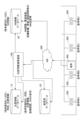
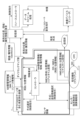
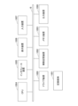
- FIG. 1 is a diagram showing an example of the overall configuration of the system.
- 1 is a configuration diagram of a position information calculation device 100.
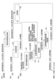
- FIG. FIG. 3 is a diagram for explaining an operation sequence.
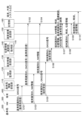
- FIG. 3 is a diagram illustrating an example of using NW state information for positioning calculations.
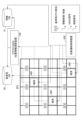
- 3 is a flowchart showing the operation of the position information calculation section 140.
- 1 is a diagram illustrating an example of an unmanned transportation system based on location information.
- FIG. 1 is a diagram showing an example of a system configuration. It is a diagram showing an example of the hardware configuration of the device.
- A/B means “A or B”. However, “A/B” does not mean “only one of A and B,” but “both A and B” is also included in the meaning of "A/B.”
- one-frequency RTK and two-frequency RTK are used, but RTK using signals of three or more frequencies, such as three-frequency RTK, may also be used.
- each database described below stores constantly updated information such as NW status (transmission delay, etc.), reference station information, position information of a terminal (positioning target), etc., obtained in real time.
- Dual frequency RTK In contrast to single-frequency RTK, which uses only L1 signals, dual-frequency RTK, which also uses L2 signals, can correct ionospheric delay due to the difference in frequency between L1 and L2 signals, reducing initialization time and improving positioning when the baseline length is long. Accuracy can be improved.
- the base station is a reference station
- the reference station used for RTK positioning is not necessarily the nearest reference station (eg, the reference station with the shortest baseline length).
- the errors associated with calculations such as ionospheric delay, tropospheric delay, and satellite orbit error, increase depending on the distance (baseline length) between the reference station and the mobile terminal. Therefore, as the baseline length increases, positioning accuracy decreases.
- the conventional technology does not support timely switching between two-frequency and one-frequency RTK depending on the baseline length.
- TTFF initialization time
- RTK positioning is based on the premise that the errors regarding the GNSS signals received by the reference station and the mobile terminal are the same at the same time. Ionospheric delay, tropospheric delay, satellite orbit error, etc. involved in calculations vary depending on the distance (baseline length) between the reference station and the mobile terminal. That is, as the baseline length increases, positioning accuracy decreases.
- the position information calculation device 100 described below performs the operations (1) to (4) below to solve the problem and improve the accuracy of RTK positioning calculations.
- the GNSS signals received at each reference station are stored in the reference station database via the NW, and the NW information is stored in the NW information database.
- the location information calculation device 100 selects the reference station with the shortest baseline length with the mobile terminal during RTK positioning calculation based on the updated database (reference station, location information).
- the location information calculation device 100 selects one-frequency RTK or two-frequency RTK according to the baseline length of the selection reference station.
- the location information calculation device 100 collects NW conditions that may affect accuracy in positioning calculations.
- the location information calculation device 100 roughly estimates the initial location required for highly accurate RTK positioning of the mobile terminal based on the NW information.
- the accuracy of RTK positioning calculations is improved by switching between 1-frequency RTK and 2-frequency RTK, selecting the reference station with the shortest baseline length, and utilizing NW information such as transmission delay information.
- NW information such as transmission delay information.
- the above operation allows switching between 1-frequency and 2-frequency RTK according to the terminal environment, and has the effect of realizing ultra-high precision and higher real-time performance.
- FIG. 1 shows a schematic configuration of a system in this embodiment.
- a location information calculation device 100 a location information database 10
- a reference station database 20 a reference station database 20
- a NW information database 30 are provided on a NW (network) 300.
- NW network 300
- mobile terminal 400 and reference stations 200 A to D).
- any or all of the location information database 10, the reference station database 20, and the NW information database 30 may be a database (storage unit) within the location information calculation device 100.
- FIG. 1 shows an image in which positioning calculations are performed on the NW side, the functions of the position information calculation device 100 may be provided on the terminal side (GNSS receiver side).
- GNSS signals (raw data) received by each reference station 200 are stored in the reference station database 20 via the NW 300. Further, the NW information is stored in the NW information database 30.
- the reference station database 20 stores a reference station identification ID, time, position information, coordinate range, and GNSS signal for each reference station.
- the "coordinate range” is the range of positions where the reference station is the closest reference station.
- the NW information includes NW quality such as NW route, radio wave strength, equipment deployment, bandwidth/delay time, etc. for the terminal.
- ⁇ S1> First, in S1, the terminal 400 connects to the NW 300.
- a terminal identification ID (EID) is assigned to the terminal 400, and the terminal 400 starts transmitting the GNSS signal and the EID that it has received to the location information calculation device 100 via the NW 300.
- the location information calculation device 100 estimates the location (initial location) of the terminal 400 at a certain time based on the NW information. This estimation can be performed using, for example, a 3GPP standard specification TDOA (Time Difference of Arrival)-based terminal position estimation technique.
- the NW information when using this terminal position estimation technique is, for example, signal propagation time between the terminal 400 and a plurality of base stations.
- the position information calculation device 100 stores the initial position estimated in S2 in the position information database 10. Note that when position information cannot be calculated based on GNSS signals, the position information is supplemented using NW information.
- the location information calculation device 100 selects a reference station to be used for RTK positioning and a positioning calculation method (two-frequency/ 1 frequency).
- the location information calculation device 100 calculates the transmission delay to be considered (of the GNSS signal) based on either or both of the NW information between itself and the terminal 400 and the NW information between itself and the reference station. (delays involved in transmission).
- the location information calculation device 100 calculates the location information of the terminal 400 based on S4 and S5 and stores it in the location information database 10. Thereafter, S4 to S6 are repeated.
- FIG. 2 shows a configuration example of the position information calculation device 100 in this embodiment. Transmission and reception of information between functional units will be described later using FIG. 3. Further, the location information calculation device 100 may be referred to as a location information performance system. The position information calculation device 100 may be implemented by one computer or by multiple computers.
- the location information calculation device 100 includes a reference station information reception section 110, a NW monitoring section 120, a terminal information reception section 130, a location information calculation section 140, a calculation result transmission section 150, and a storage section 160.
- the storage unit 160 corresponds to the location information database 10, reference station database 20, and NW information database 30 described above.
- the storage unit 160 may be provided outside the position information calculation device 100.
- the location information calculation unit 140 includes an acquisition unit 141 that acquires information from the storage unit 160.
- the acquisition unit 141 may be located outside the position information calculation unit 140.
- the reference station information receiving unit 110 receives the reference station identification ID and the GNSS signal (receive reference station) transmitted from the reference station 200.
- the reference station information receiving section 110 stores (transmits) the reference station identification ID and the GNSS signal (reference station reception) in the storage section 160.
- the NW monitoring unit 120 receives the terminal identification ID and NW information from the NW 300, and stores them in the storage unit 160 in S104.
- the terminal information receiving unit 130 receives the terminal identification ID and the GNSS signal (terminal reception) from the terminal 400, and in S106 notifies the location information calculation unit 140 of these.
- the location information calculation unit 140 references (obtains) the terminal identification ID, NW information, time, location information, reference station identification ID, coordinate range, and GNSS signal (reference station reception) from the storage unit 160.
- the location information calculation unit 140 calculates the time and location information of the terminal 400 based on the information received from the terminal 400 and the information acquired from the storage unit 160.
- the location information calculation unit 140 notifies the calculation result transmission unit 150 of the terminal identification ID, time, and location information.
- the calculation result transmitting unit 150 stores the terminal identification ID, time, and location information in the storage unit 160, and transmits the information to the terminal, external system, etc. (S109, S110).
- the time required for transmitting and receiving information between u and F regarding GNSS signals (terminal reception) (e.g. signal propagation time from u to F) is set as t1
- the time required for transmitting and receiving information between s and F regarding GNSS signals (reference station reception) is set as t1.
- the information transmission/reception time difference ⁇ t t 2 -t 1 .
- ⁇ t obtained by monitoring the status of NW/server resources is notified to F and used for positioning calculations. In other words, a system that utilizes NW information will be realized.
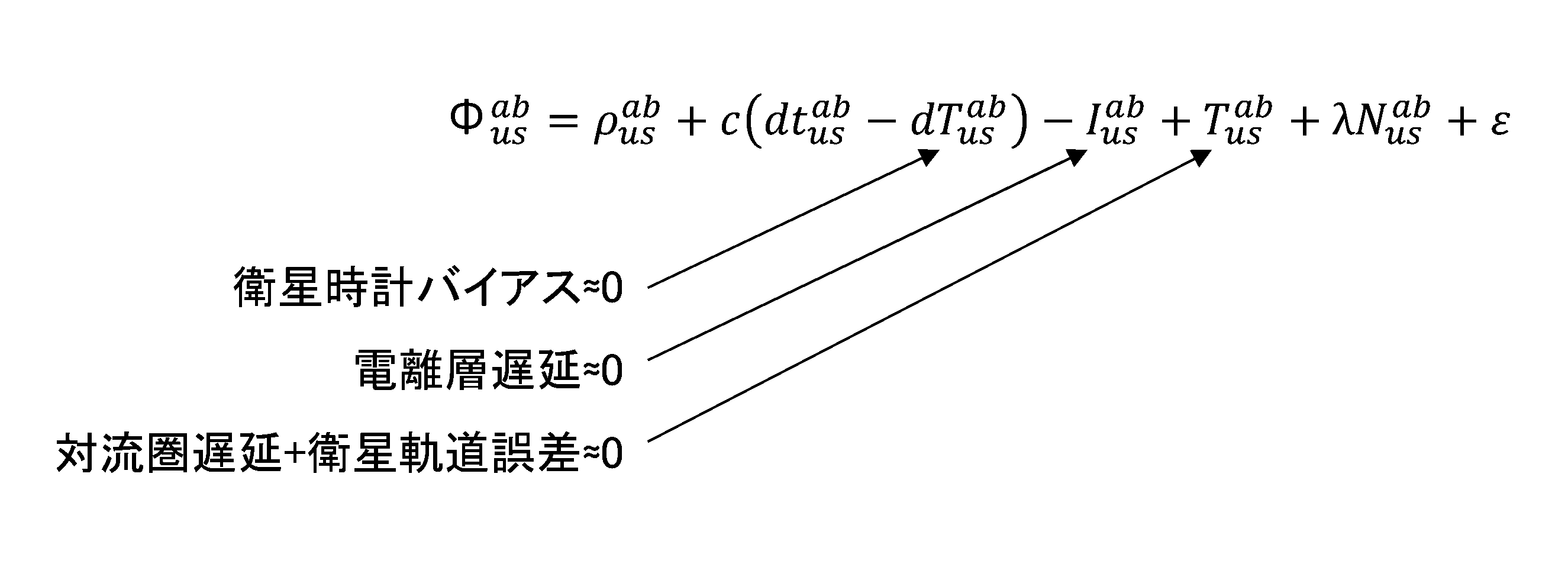
- the carrier phase observed value ⁇ is expressed as follows.
- ⁇ Carrier phase (m) ⁇ : Geometric distance between satellite and receiver (m) c: Speed of light (m/s) dt: Receiver clock error (s) dT: Satellite clock error (s) I: Ionospheric delay amount (m) T: Tropospheric delay amount (m) ⁇ : Wavelength (m) N: Carrier phase bias (cycle) ⁇ : Noise (m)
- the double phase difference of the carrier wave phase is expressed as follows.
- Satellite clock correction (when t 2 >t 1 ) is calculated as follows.
- the portion of ⁇ t is varied in real time.
- the delayed result can be reflected in the positioning calculation function unit F.
- the positioning calculation function unit F in FIG. 4 corresponds to the position information calculation unit 140 of the position information calculation device 100.
- the positioning calculation function unit F may be a function on the terminal side or may be a function on the NW side.
- the NW side functional unit 6 corresponds to, for example, the NW monitoring unit 120 of the location information calculation device 100.
- the NW monitoring unit 120 calculates ⁇ t and notifies the position information calculation unit 140 of ⁇ t.
- the NW monitoring unit 120 may calculate ⁇ t and store ⁇ t in the storage unit 160 (database), and the position information calculation unit 140 may read ⁇ t from the storage unit 160.
- the position information calculation unit 140 executes calculations expressed by equations 1 and 2.
- the NW monitoring unit 120 stores the transmission delays (t 1 and t 2 ) in the storage unit 160 (database), and the position information calculation unit 140 reads the transmission delays (t 1 and t 2 ) from the storage unit 160. By doing so, ⁇ t may be calculated, and position information may be calculated using the ⁇ t.
- the location information calculation unit 140 receives a terminal identification ID and a GNSS signal (terminal reception) from the terminal information reception unit 130.
- the location information calculation unit 140 refers to the time and location information of the terminal 400 stored in the storage unit 160 based on the terminal identification ID.
- the location information calculation unit 140 checks whether the time and location information (GNSS base) of the terminal 400 is stored in the storage unit 160. If the determination result in S203 is Yes, the process advances to S204, and if the determination result is No, the process advances to S205.
- the location information calculation unit 140 refers to the reference station identification ID and coordinate range stored in the storage unit 160, and calculates the time and location information based on the time and location information (GNSS base) of the terminal 400. Select the reference station identification ID to be used for (GNSS-based) calculations. In other words, a reference station is selected in which the terminal 400 is located within the coordinate range (range of positions where the reference station is the closest reference station) and which has the shortest baseline length with the terminal 400. From now on, the same applies when selecting the reference station identification ID. After S204, the process advances to S210.
- the location information calculation unit 140 checks whether the time and location information (NW information base) of the terminal 400 is stored in the storage unit 160. If the determination result in S205 is Yes, the process advances to S209, and if the determination result is No, the process advances to S206.
- the location information calculation unit 140 refers to the NW information stored in the storage unit 160 based on the terminal identification ID.
- the location information calculation unit 140 calculates the time and location information (NW information base) of the terminal 400 based on the NW information.
- the location information calculation unit 140 transmits the time and location information (NW information base) of the terminal 400 to the storage unit 160.
- the location information calculation unit 140 refers to the reference station identification ID, time, location information, coordinate range, and GNSS signal stored in the storage unit 160, and calculates the information based on the time and location information (NW information base) of the terminal 400. Then, select the reference station identification ID to be used for calculating time and position information (GNSS base).
- the location information calculation unit 140 determines whether the GNSS signal (terminal reception) received from the terminal information reception unit 130 is compatible with two-frequency RTK (both L1 and L2). If the determination result in S210 is Yes, the process advances to S211, and if the determination result is No, the process advances to S213.
- the position information calculation unit 140 determines whether "L ⁇ L th ". If the determination result in S211 is Yes, the process advances to S212, and if the determination result is No, the process advances to S213.
- L is the distance (baseline length) between the terminal 400 and the reference station 200
- L th is a threshold value at which the precision of two-frequency RTK positioning is better than that of one-frequency RTK positioning.
- the location information calculation unit 140 refers to the NW information stored in the storage unit 160 based on the terminal identification ID, and calculates the time and location information (GNSS base).
- the location information calculation unit 140 refers to the NW information stored in the storage unit 160 based on the terminal identification ID, and calculates the time and location information (GNSS base).
- the location information calculation unit 140 transmits the time and location information (GNSS base) of the terminal 400 to the storage unit 214, and also to the terminal, external system, etc.
- the location information calculation device 100 that can appropriately calculate the location information of the terminal 400 in a situation where the nearest reference station and NW transmission delay change due to terminal movement can be applied to various fields.
- an example of an unmanned transportation system based on highly accurate location information of a terminal through RTK positioning will be described with reference to FIG.
- a location information calculation device 100 is provided as a cloud GNSS function.
- an automatic driving control device 500 is provided that controls the terminal 400 (eg, stopping, decelerating) based on the position information of the terminal 400 (self-driving car, etc.).
- the automatic driving control device 500 may be an independent device, a functional unit within the position information calculation device 100, or a functional unit within the terminal 400.
- a reference station DB 20 and an information DB 15 are provided.
- the information DB15 corresponds to the location information DB10 and the NW information DB30.
- the location information calculation device 100 performs positioning calculations for the terminal 400 based on the GNSS signal reception results (Raw data) transmitted from the terminal 400 and the GNSS signal reception results (Raw data, reference station data) at the reference station 200, and performs calculations.
- the resulting location information of the terminal 400 is stored in the information DB 15.
- the automatic driving control device 500 performs automatic driving control on the terminal 400 by referring to the position information of the terminal 400 in the information DB 15.
- the location information calculation device 100 described in this embodiment may be used in a location information distribution infrastructure as shown in FIG.
- the advanced positioning infrastructure 1 in FIG. 7 may have the function of the location information calculation device 100
- the controller 2 may have the function of the location information calculation device 100
- both the advanced positioning infrastructure 1 and the controller 2 may have the functions of the location information calculation device 100.
- the functions of the position information calculation device 100 may be realized by this.
- FIG. 7 shows, as an example, an example in which video transmitted by a vehicle is controlled.
- NW is an abbreviation for Network
- EID is an abbreviation for Endpoint Identifier
- CPE is an abbreviation for Customer Premises Equipment
- NMEA is an abbreviation for NMEA0183
- NMEA itself is an abbreviation for National Marine. Abbreviation for Electronics Association.
- the above-described location information calculation device 100 can be realized, for example, by causing a computer to execute a program that describes the processing contents described in this embodiment.
- This computer may be a physical computer or a virtual machine on the cloud.
- the position information calculation device 100 can be realized by using hardware resources such as a CPU and memory built into a computer to execute a program corresponding to the processing performed by the device.
- the above program can be recorded on a computer-readable recording medium (such as a portable memory) and can be stored or distributed. It is also possible to provide the above program through a network such as the Internet or e-mail.
- FIG. 8 is a diagram showing an example of the hardware configuration of the computer.
- the computer in FIG. 8 includes a drive device 1000, an auxiliary storage device 1002, a memory device 1003, a CPU 1004, an interface device 1005, a display device 1006, an input device 1007, an output device 1008, etc., which are interconnected by a bus BS.
- a program that realizes processing on the computer is provided, for example, on a recording medium 1001 such as a CD-ROM or a memory card.
- a recording medium 1001 such as a CD-ROM or a memory card.
- the program is installed from the recording medium 1001 to the auxiliary storage device 1002 via the drive device 1000.
- the program does not necessarily need to be installed from the recording medium 1001, and may be downloaded from another computer via a network.
- the auxiliary storage device 1002 stores installed programs as well as necessary files, data, and the like.
- the memory device 1003 reads and stores the program from the auxiliary storage device 1002 when there is an instruction to start the program.
- CPU 1004 implements functions related to control device 100 according to programs stored in memory device 1003.
- the interface device 1005 is used as an interface for connecting to a network or the like.
- a display device 1006 displays a GUI (Graphical User Interface) and the like based on a program.
- the input device 1007 is composed of a keyboard, a mouse, buttons, a touch panel, or the like, and is used to input various operation instructions.
- An output device 1008 outputs the calculation result.
- the location information calculation device 100 selects a reference station with the shortest baseline length between it and the terminal 400 that is the positioning target during RTK positioning calculation, based on a database (reference station, location information) that is updated each time. do.
- a database reference station, location information
- the location information calculation device 100 selects one-frequency RTK or two-frequency RTK depending on the baseline length of the selected reference station. This makes it possible to improve accuracy by taking into account ionospheric delay in response to changes in baseline length due to terminal movement.
- the location information calculation device 100 collects and utilizes NW conditions that may affect accuracy in positioning calculations that involve transmission and reception of GNSS signal reception results via the NW. This makes it possible to reflect the ever-changing state of the NW connected to the mobile terminal/reference station in the positioning calculation, thereby improving accuracy.
- the location information calculation device 100 roughly calculates the initial location required for highly accurate RTK positioning of the mobile terminal based on the NW information. This eliminates the need to estimate the initial position on the terminal side, and also eliminates the need to transmit the initial position estimate result from the terminal to the upper side via the NW. As a result, the terminal can be simplified.
- the location information calculation device 100 when the location information calculation device 100 cannot calculate the location information based on GNSS, it can calculate the location information based on the NW information and perform complementation. This enables flexible operation that combines location information weighting and multi-stage failsafe.
- a location information calculation device that calculates location information of a positioning target using observation data of a reference station, an acquisition unit that acquires reference station information and position information of the positioning target from a database; Based on the reference station information and the position information, a reference station having the shortest baseline length with the positioning target is selected, and position information of the positioning target is calculated using a positioning calculation method according to the base line length.
- a location information calculation device comprising: a location information calculation section; (Additional note 2)
- the positioning calculation method is one-frequency RTK or two-frequency RTK, and the position information calculation unit calculates the position information of the positioning target using the two-frequency RTK when the baseline length is greater than or equal to a threshold value.
- the location information calculation device according to Supplementary Note 1, which calculates .
- the position according to supplementary note 1 or 2 wherein the acquisition unit acquires transmission delay information of observation data from a database, and the position information calculation unit calculates the position information of the positioning target using the transmission delay information.
- Information computing device is one-frequency RTK or two-frequency RTK, and the position information calculation unit calculates the position information of the positioning target using the two-frequency RTK when the baseline length is greater than or equal to a threshold value.
- the acquisition unit acquires NW information from a database, and the position information calculation unit uses the NW information to calculate the initial position of the positioning target in the positioning calculation method.
- the location information calculation device according to item 1.
- the position information calculation device according to any one of Supplementary Notes 1 to 4, wherein the position information calculation unit calculates position information used to perform automatic driving control for the positioning target.
- a location information calculation method executed by a location information calculation device that calculates location information of a positioning target using observation data of a reference station, an acquisition step of acquiring reference station information and position information of the positioning target from a database; Based on the reference station information and the position information, a reference station having the shortest baseline length with the positioning target is selected, and position information of the positioning target is calculated using a positioning calculation method according to the base line length.
- a location information calculation method comprising a location information calculation step.
- Location information database 20 Reference station database 30 NW information database 100 Location information calculation device 110 Reference station information reception unit 120 NW monitoring unit 130 Terminal information reception unit 140 Location information calculation unit 141 Acquisition unit 150 Calculation result transmission unit 160 Storage unit 200 Reference station 300 NW 400 Terminal 500 Automatic operation control device 1000 Drive device 1001 Recording medium 1002 Auxiliary storage device 1003 Memory device 1004 CPU 1005 Interface device 1006 Display device 1007 Input device 1008 Output device
Landscapes
- Engineering & Computer Science (AREA)
- Radar, Positioning & Navigation (AREA)
- Remote Sensing (AREA)
- Computer Networks & Wireless Communication (AREA)
- Physics & Mathematics (AREA)
- General Physics & Mathematics (AREA)
- Position Fixing By Use Of Radio Waves (AREA)
- Radar Systems Or Details Thereof (AREA)
Abstract
Description
データベースから基準局情報及び前記測位対象の位置情報を取得する取得部と、
前記基準局情報及び前記位置情報に基づいて、前記測位対象との間の基線長が最も短い基準局を選定し、前記基線長に応じた測位演算方式を使用して前記測位対象の位置情報を算出する位置情報演算部と
を備える位置情報演算装置が提供される。
<既存のRTK測位について>
まず、RTK測位の仕組み(整数値バイアスの確定=初期化を含む)と、測位精度の低下要因と、基準局と移動局との関係性(特に情報のやり取り、伝送路のところ)について説明する。
L1信号のみを用いる1周波RTKに対してL2信号も用いる2周波RTKでは、L1信号とL2信号の周波数の違いにより電離層遅延を補正できるため、初期化時間の短縮および基線長が長い場合の測位精度の向上が可能となる。
移動端末が接続する基地局間のハンドオーバに併せて基準局を切り替えることで、移動端末最寄りの基準局のデータをRTK測位に用いる。これにより、初期化時間の短縮および測位精度の向上を可能としている。
従来の測位演算の過程では、伝送遅延を固定量として考慮することで測位精度の向上を可能としている。しかし、従来技術は、NW環境が時々刻々と変化する移動端末には対応していない。
従来技術では、端末が受信するGNSS信号が一瞬でも途切れるとその都度初期化が走るため、単独測位やRTK Floatに移行してしまうことで測位精度の低下が発生する。再度RTK Fixに移行するまでの時間(=初期化時間(TTFF))は、見通しが良い環境でも数十秒オーダ(環境により数分以上のオーダにもなり得る)になる。そのため、TTFFを短縮することが必要である。
図1に、本実施の形態におけるシステムの概要構成を示す。図1に示すように、NW(ネットワーク)300上に、位置情報演算装置100、位置情報データベース10、基準局データベース20、NW情報データベース30が備えられる。また、移動する端末400、及び基準局200(A~D)が存在する。
各基準局200で受信したGNSS信号(rawデータ)はNW300を介して基準局データベース20に格納されている。また、NW情報はNW情報データベース30に格納されている。
まず、S1において、端末400がNW300に接続する。ここでは、端末400に端末識別ID(EID)が付与され、端末400は、自身が受信したGNSS信号、及びEIDを位置情報演算装置100へNW300を介して送信することを開始する。
S2において、位置情報演算装置100が、NW情報に基づいて、ある時刻の端末400の位置(初期位置)を推定する。この推定は、例えば、3GPP標準仕様のTDOA(Time Difference of Arrival)ベースの端末位置推定技術を用いて行うことができる。この端末位置推定技術を用いる場合のNW情報は、例えば、端末400と複数の基地局との間の信号伝搬時間である。
S3において、位置情報演算装置100は、S2で推定した初期位置を位置情報データベース10に格納する。なお、GNSS信号ベースで位置情報が演算できないときはNW情報ベースで位置情報を補完する。位置情報データベース10には、端末毎に、端末識別ID(=EID)、時刻、位置情報が格納される。
S4において、位置情報演算装置100は、各データベースに格納されている端末400の時刻及び位置情報、及び、既知の基準局位置に基づいて、RTK測位に使用する基準局と、測位演算方式(2周波/1周波)を決定する。
S5において、位置情報演算装置100は、自身と端末400との間のNW情報、及び、自身と基準局との間のNW情報、のいずれか又は両方に基づいて、考慮する伝送遅延(GNSS信号の伝送に関わる遅延)を決定する。
S6において、位置情報演算装置100は、S4及びS5に基づいて、端末400の位置情報を演算して位置情報データベース10に格納する。以降、S4~S6が繰り返される。
図2に、本実施の形態における位置情報演算装置100の構成例を示す。機能部間の情報の送受信については、図3を用いて後述する。また、位置情報演算装置100を位置情報演システムと呼んでもよい。位置情報演算装置100は、1つのコンピュータで実現してもよいし、複数のコンピュータで実現してもよい。
次に、遅延時間算出と測位演算機能について説明する。図4に示すように、衛星a,b、端末u(測位対象である受信機)、基準局sがある状況を想定する。また、測位演算機能部F、NW側機能部6が存在する。なお、図4に示す、衛星a、b、端末u、基準局sを有する構成、及び、以下で数式を用いて説明している搬送波位相観測値Φ、搬送波位相の二重位相差の計算方法は、「https://www.denshi.e.kaiyodai.ac.jp/kubo/isejima.pdf」に開示されている。
各記号の意味は下記のとおりである。
ρ:衛星と受信機間の幾何学距離(m)
c:光速(m/s)
dt:受信機時計誤差(s)
dT:衛星時計誤差(s)
I:電離層遅延量(m)
T:対流圏遅延量(m)
λ:波長(m)
N:搬送波位相バイアス(cycle)
ε:ノイズ(m)
搬送波位相の二重位相差は下記のように表される。

次に、図5のフローチャートに基づき、位置情報演算部140の処理手順の例を説明する。S201において、位置情報演算部140は、端末情報受信部130から端末識別IDとGNSS信号(端末受信)を受信する。S202において、位置情報演算部140は、端末識別IDに基づき、記憶部160に格納されている端末400の時刻、位置情報を参照する。S203において、位置情報演算部140は、記憶部160に、端末400の時刻、位置情報(GNSSベース)が格納されているか否かを確認する。S203の判断結果がYesであればS204に進み、NoであればS205に進む。
端末移動による最近接基準局及びNW伝送遅延が変化する状況で、適切に端末400の位置情報を算出できる位置情報演算装置100は、様々な分野に適用することができる。ここでは、一例として、RTK測位による端末の高精度な位置情報に基づく無人輸送システムの例を、図6を参照して説明する。
本実施の形態で説明した位置情報演算装置100は、図7に示すような位置情報流通基盤で用いられてもよい。図7における高度測位基盤1が位置情報演算装置100の機能を有してもよいし、コントローラ2が位置情報演算装置100の機能を有してもよいし、高度測位基盤1とコントローラ2の両方により、位置情報演算装置100の機能を実現してもよい。
上述した位置情報演算装置100は、例えば、コンピュータに、本実施の形態で説明する処理内容を記述したプログラムを実行させることにより実現可能である。このコンピュータは、物理的なコンピュータであってもよいし、クラウド上の仮想マシンであってもよい。
本実施の形態に係る位置情報演算装置100は、都度更新されるデータベース(基準局、位置情報)に基づいて、測位対象である端末400との間の基線長が最も短い基準局をRTK測位演算時に選定する。これにより、最近接基準局のGNSS信号を利用できるので、初期化時間が短縮でき、測位精度が向上する。
以上の実施形態に関し、更に以下の付記項を開示する。
(付記項1)
基準局の観測データを用いて測位対象の位置情報を算出する位置情報演算装置であって、
データベースから基準局情報及び前記測位対象の位置情報を取得する取得部と、
前記基準局情報及び前記位置情報に基づいて、前記測位対象との間の基線長が最も短い基準局を選定し、前記基線長に応じた測位演算方式を使用して前記測位対象の位置情報を算出する位置情報演算部と
を備える位置情報演算装置。
(付記項2)
前記測位演算方式は、1周波RTK、又は、2周波RTKであり、前記位置情報演算部は、前記基線長が閾値以上である場合に、前記2周波RTKを使用して前記測位対象の位置情報を算出する
付記項1に記載の位置情報演算装置。
(付記項3)
前記取得部は、データベースから観測データの伝送遅延情報を取得し、前記位置情報演算部が、前記伝送遅延情報を用いて、前記測位対象の位置情報を算出する
付記項1又は2に記載の位置情報演算装置。
(付記項4)
前記取得部は、データベースからNW情報を取得し、前記位置情報演算部が、前記NW情報を使用して、前記測位演算方式における前記測位対象の初期位置を算出する
付記項1ないし3のうちいずれか1項に記載の位置情報演算装置。
(付記項5)
前記位置情報演算部は、前記測位対象に対する自動運転制御を行うために使用する位置情報を算出する
付記項1ないし4のうちいずれか1項に記載の位置情報演算装置。
(付記項6)
基準局の観測データを用いて測位対象の位置情報を算出する位置情報演算装置が実行する位置情報演算方法であって、
データベースから基準局情報及び前記測位対象の位置情報を取得する取得ステップと、
前記基準局情報及び前記位置情報に基づいて、前記測位対象との間の基線長が最も短い基準局を選定し、前記基線長に応じた測位演算方式を使用して前記測位対象の位置情報を算出する位置情報演算ステップと
を備える位置情報演算方法。
(付記項7)
コンピュータを、付記項1ないし5のうちいずれか1項に記載の位置情報演算装置における各部として機能させるためのプログラムを記憶した非一時的記憶媒体。
20 基準局データベース
30 NW情報データベース
100 位置情報演算装置
110 基準局情報受信部
120 NW監視部
130 端末情報受信部
140 位置情報演算部
141 取得部
150 演算結果送信部
160 記憶部
200 基準局
300 NW
400 端末
500 自動運転制御装置
1000 ドライブ装置
1001 記録媒体
1002 補助記憶装置
1003 メモリ装置
1004 CPU
1005 インタフェース装置
1006 表示装置
1007 入力装置
1008 出力装置
Claims (7)
- 基準局の観測データを用いて測位対象の位置情報を算出する位置情報演算装置であって、
データベースから基準局情報及び前記測位対象の位置情報を取得する取得部と、
前記基準局情報及び前記位置情報に基づいて、前記測位対象との間の基線長が最も短い基準局を選定し、前記基線長に応じた測位演算方式を使用して前記測位対象の位置情報を算出する位置情報演算部と
を備える位置情報演算装置。 - 前記測位演算方式は、1周波RTK、又は、2周波RTKであり、前記位置情報演算部は、前記基線長が閾値以上である場合に、前記2周波RTKを使用して前記測位対象の位置情報を算出する
請求項1に記載の位置情報演算装置。 - 前記取得部は、データベースから観測データの伝送遅延情報を取得し、前記位置情報演算部が、前記伝送遅延情報を用いて、前記測位対象の位置情報を算出する
請求項1に記載の位置情報演算装置。 - 前記取得部は、データベースからNW情報を取得し、前記位置情報演算部が、前記NW情報を使用して、前記測位演算方式における前記測位対象の初期位置を算出する
請求項1に記載の位置情報演算装置。 - 前記位置情報演算部は、前記測位対象に対する自動運転制御を行うために使用する位置情報を算出する
請求項1に記載の位置情報演算装置。 - 基準局の観測データを用いて測位対象の位置情報を算出する位置情報演算装置が実行する位置情報演算方法であって、
データベースから基準局情報及び前記測位対象の位置情報を取得する取得ステップと、
前記基準局情報及び前記位置情報に基づいて、前記測位対象との間の基線長が最も短い基準局を選定し、前記基線長に応じた測位演算方式を使用して前記測位対象の位置情報を算出する位置情報演算ステップと
を備える位置情報演算方法。 - コンピュータを、請求項1ないし5のうちいずれか1項に記載の位置情報演算装置における各部として機能させるためのプログラム。
Priority Applications (3)
| Application Number | Priority Date | Filing Date | Title |
|---|---|---|---|
| US18/878,753 US20250383456A1 (en) | 2022-07-04 | 2022-07-04 | Position information calculation apparatus, position information calculation method, and program |
| JP2024531774A JPWO2024009366A1 (ja) | 2022-07-04 | 2022-07-04 | |
| PCT/JP2022/026629 WO2024009366A1 (ja) | 2022-07-04 | 2022-07-04 | 位置情報演算装置、位置情報演算方法、及びプログラム |
Applications Claiming Priority (1)
| Application Number | Priority Date | Filing Date | Title |
|---|---|---|---|
| PCT/JP2022/026629 WO2024009366A1 (ja) | 2022-07-04 | 2022-07-04 | 位置情報演算装置、位置情報演算方法、及びプログラム |
Publications (1)
| Publication Number | Publication Date |
|---|---|
| WO2024009366A1 true WO2024009366A1 (ja) | 2024-01-11 |
Family
ID=89452943
Family Applications (1)
| Application Number | Title | Priority Date | Filing Date |
|---|---|---|---|
| PCT/JP2022/026629 Ceased WO2024009366A1 (ja) | 2022-07-04 | 2022-07-04 | 位置情報演算装置、位置情報演算方法、及びプログラム |
Country Status (3)
| Country | Link |
|---|---|
| US (1) | US20250383456A1 (ja) |
| JP (1) | JPWO2024009366A1 (ja) |
| WO (1) | WO2024009366A1 (ja) |
Citations (4)
| Publication number | Priority date | Publication date | Assignee | Title |
|---|---|---|---|---|
| WO2019081382A2 (en) * | 2017-10-24 | 2019-05-02 | Waysure Sweden Ab | REFERENCE STATION TRANSFER |
| JP2020085824A (ja) * | 2018-11-30 | 2020-06-04 | Ales株式会社 | 測位システム、サーバ、測位方法、測位対象の装置及び移動体 |
| WO2021220418A1 (ja) * | 2020-04-28 | 2021-11-04 | 日本電信電話株式会社 | 基準局選択装置、基準局選択方法、及びプログラム |
| JP2022525581A (ja) * | 2019-01-04 | 2022-05-18 | マゼランシステムズジャパン株式会社 | 高精度な単独測位機能を有する自律型基準局 |
-
2022
- 2022-07-04 WO PCT/JP2022/026629 patent/WO2024009366A1/ja not_active Ceased
- 2022-07-04 US US18/878,753 patent/US20250383456A1/en active Pending
- 2022-07-04 JP JP2024531774A patent/JPWO2024009366A1/ja active Pending
Patent Citations (4)
| Publication number | Priority date | Publication date | Assignee | Title |
|---|---|---|---|---|
| WO2019081382A2 (en) * | 2017-10-24 | 2019-05-02 | Waysure Sweden Ab | REFERENCE STATION TRANSFER |
| JP2020085824A (ja) * | 2018-11-30 | 2020-06-04 | Ales株式会社 | 測位システム、サーバ、測位方法、測位対象の装置及び移動体 |
| JP2022525581A (ja) * | 2019-01-04 | 2022-05-18 | マゼランシステムズジャパン株式会社 | 高精度な単独測位機能を有する自律型基準局 |
| WO2021220418A1 (ja) * | 2020-04-28 | 2021-11-04 | 日本電信電話株式会社 | 基準局選択装置、基準局選択方法、及びプログラム |
Also Published As
| Publication number | Publication date |
|---|---|
| JPWO2024009366A1 (ja) | 2024-01-11 |
| US20250383456A1 (en) | 2025-12-18 |
Similar Documents
| Publication | Publication Date | Title |
|---|---|---|
| CN108027443B (zh) | 用于在实时运动模式与精确定位模式之间切换的卫星导航接收器及方法 | |
| CN107710016B (zh) | 用于在实时运动模式与精确定位模式之间切换的卫星导航接收器及方法 | |
| US7970419B2 (en) | Systems, devices and methods for location determination | |
| WO2022142834A1 (zh) | 自差分定位方法、装置、移动设备及存储介质 | |
| JP6593879B2 (ja) | 衛星測位システム、測位端末、測位方法、及びプログラム | |
| AU2017436819A1 (en) | RTK vector phase locked loop architecture | |
| EP2612167A1 (en) | Automatic blade control system during a period of a global navigation satellite system real-time kinematic mode system outage | |
| JP7443500B2 (ja) | 基準局選択装置、基準局選択方法、及びプログラム | |
| AU2011283202A1 (en) | System and method for moving-base RTK measurements | |
| JP2000304854A (ja) | 目標追尾方法及び目標追尾装置 | |
| CN114174870A (zh) | 用于确定描述至少一个特定于环境的gnss曲线的模型的方法 | |
| CN109541660B (zh) | 一种vrs切换的方法、接收机、可读介质及云服务器 | |
| CA3160240A1 (en) | Estimating terminal location in a satellite communication system | |
| JP2022007629A (ja) | 異常判定装置、異常判定方法、及び異常判定プログラム | |
| CN115623414A (zh) | 移动通信系统中的定位 | |
| US20140156179A1 (en) | Apparatus and method for use in global position measurements | |
| CN113568004A (zh) | 用于确定对估计的局部状态矢量的更新的估计器 | |
| US12585031B2 (en) | Collaborative geolocation estimation | |
| JP2010210436A (ja) | Gps受信機搬送波位相測定値の品質監視装置、方法、プログラム | |
| US20250383456A1 (en) | Position information calculation apparatus, position information calculation method, and program | |
| JP2014044056A (ja) | 測位装置、測位方法および測位プログラム | |
| JP2006258461A (ja) | 測位装置、測位方法および測位プログラム | |
| US12270916B2 (en) | System and method for aiding data processing for signals of opportunity-based assured position, navigation and timing (PNT) | |
| KR20250095472A (ko) | 이동성이 있는 릴레이가 탑재된 네트워크의 isac 기반 위치 추적 및 신호 전송 방법 및 그 시스템 | |
| CN119533482A (zh) | 一种基于多源定位数据融合的船舶进坞定位方法及系统 |
Legal Events
| Date | Code | Title | Description |
|---|---|---|---|
| 121 | Ep: the epo has been informed by wipo that ep was designated in this application |
Ref document number: 22950161 Country of ref document: EP Kind code of ref document: A1 |
|
| WWE | Wipo information: entry into national phase |
Ref document number: 2024531774 Country of ref document: JP |
|
| WWE | Wipo information: entry into national phase |
Ref document number: 18878753 Country of ref document: US |
|
| NENP | Non-entry into the national phase |
Ref country code: DE |
|
| 122 | Ep: pct application non-entry in european phase |
Ref document number: 22950161 Country of ref document: EP Kind code of ref document: A1 |
|
| WWP | Wipo information: published in national office |
Ref document number: 18878753 Country of ref document: US |