WO2024005170A1 - 結束装置 - Google Patents
結束装置 Download PDFInfo
- Publication number
- WO2024005170A1 WO2024005170A1 PCT/JP2023/024295 JP2023024295W WO2024005170A1 WO 2024005170 A1 WO2024005170 A1 WO 2024005170A1 JP 2023024295 W JP2023024295 W JP 2023024295W WO 2024005170 A1 WO2024005170 A1 WO 2024005170A1
- Authority
- WO
- WIPO (PCT)
- Prior art keywords
- wire
- binding
- reel
- pull
- section
- Prior art date
- Legal status (The legal status is an assumption and is not a legal conclusion. Google has not performed a legal analysis and makes no representation as to the accuracy of the status listed.)
- Ceased
Links
Images













Classifications
-
- E—FIXED CONSTRUCTIONS
- E04—BUILDING
- E04G—SCAFFOLDING; FORMS; SHUTTERING; BUILDING IMPLEMENTS OR AIDS, OR THEIR USE; HANDLING BUILDING MATERIALS ON THE SITE; REPAIRING, BREAKING-UP OR OTHER WORK ON EXISTING BUILDINGS
- E04G21/00—Preparing, conveying, or working-up building materials or building elements in situ; Other devices or measures for constructional work
- E04G21/12—Mounting of reinforcing inserts; Prestressing
- E04G21/122—Machines for joining reinforcing bars
- E04G21/123—Wire twisting tools
-
- B—PERFORMING OPERATIONS; TRANSPORTING
- B21—MECHANICAL METAL-WORKING WITHOUT ESSENTIALLY REMOVING MATERIAL; PUNCHING METAL
- B21F—WORKING OR PROCESSING OF METAL WIRE
- B21F15/00—Connecting wire to wire or other metallic material or objects; Connecting parts by means of wire
- B21F15/02—Connecting wire to wire or other metallic material or objects; Connecting parts by means of wire wire with wire
- B21F15/06—Connecting wire to wire or other metallic material or objects; Connecting parts by means of wire wire with wire with additional connecting elements or material
-
- B—PERFORMING OPERATIONS; TRANSPORTING
- B21—MECHANICAL METAL-WORKING WITHOUT ESSENTIALLY REMOVING MATERIAL; PUNCHING METAL
- B21F—WORKING OR PROCESSING OF METAL WIRE
- B21F7/00—Twisting wire; Twisting wire together
-
- B—PERFORMING OPERATIONS; TRANSPORTING
- B65—CONVEYING; PACKING; STORING; HANDLING THIN OR FILAMENTARY MATERIAL
- B65B—MACHINES, APPARATUS OR DEVICES FOR, OR METHODS OF, PACKAGING ARTICLES OR MATERIALS; UNPACKING
- B65B13/00—Bundling articles
- B65B13/02—Applying and securing binding material around articles or groups of articles, e.g. using strings, wires, strips, bands or tapes
- B65B13/025—Hand-held tools
-
- B—PERFORMING OPERATIONS; TRANSPORTING
- B65—CONVEYING; PACKING; STORING; HANDLING THIN OR FILAMENTARY MATERIAL
- B65B—MACHINES, APPARATUS OR DEVICES FOR, OR METHODS OF, PACKAGING ARTICLES OR MATERIALS; UNPACKING
- B65B13/00—Bundling articles
- B65B13/02—Applying and securing binding material around articles or groups of articles, e.g. using strings, wires, strips, bands or tapes
- B65B13/04—Applying and securing binding material around articles or groups of articles, e.g. using strings, wires, strips, bands or tapes with means for guiding the binding material around the articles prior to severing from supply
-
- B—PERFORMING OPERATIONS; TRANSPORTING
- B65—CONVEYING; PACKING; STORING; HANDLING THIN OR FILAMENTARY MATERIAL
- B65B—MACHINES, APPARATUS OR DEVICES FOR, OR METHODS OF, PACKAGING ARTICLES OR MATERIALS; UNPACKING
- B65B13/00—Bundling articles
- B65B13/18—Details of, or auxiliary devices used in, bundling machines or bundling tools
- B65B13/185—Details of tools
- B65B13/186—Supports or tables facilitating tensioning operations
-
- B—PERFORMING OPERATIONS; TRANSPORTING
- B65—CONVEYING; PACKING; STORING; HANDLING THIN OR FILAMENTARY MATERIAL
- B65B—MACHINES, APPARATUS OR DEVICES FOR, OR METHODS OF, PACKAGING ARTICLES OR MATERIALS; UNPACKING
- B65B13/00—Bundling articles
- B65B13/18—Details of, or auxiliary devices used in, bundling machines or bundling tools
- B65B13/22—Means for controlling tension of binding means
Definitions
- It relates to a binding device that binds reinforcing bars with wire.
- Reinforcing bars are used in concrete buildings to improve their strength, and they are tied with wire to prevent the reinforcing bars from shifting from their predetermined positions during concrete pouring.
- a binding machine called a reinforcing bar binding machine has been proposed, which wraps wire around two or more reinforcing bars, twists the wire wound around the reinforcing bars, and ties the two or more reinforcing bars with the wire.
- the reel on which the wire is wound should be made larger than the reel that can be loaded into the conventional reinforcing bar binding machine to increase the capacity of wire. is possible.
- the present invention was made to solve such problems, and an object of the present invention is to provide a binding device that can reliably draw out the amount of wire necessary for binding reinforcing bars.
- the present disclosure provides a binding mechanism that sends wires around reinforcing bars, twists and ties the wires sent around the reinforcing bars, and connects the bundling mechanism to a binding position where the reinforcing bars are tied and from the reinforcing bars.
- a binding mechanism moving part that moves the binding mechanism to and from a separate retracted position, and a wire pulling part that pulls out the wire wound on the reel, and the wire pulling part includes a transmission part to which the operation of the binding mechanism moving part is transmitted.
- the transmission unit is a binding device in which the amount of wire pulled out by the wire pulling unit is varied with respect to the amount of movement of the binding mechanism moved by the operation of the binding mechanism moving unit.
- the amount of wire pulled out at the wire pull-out section is varied with respect to the amount of movement of the tying mechanism in the operation of moving the tying mechanism between the tying position and the retracted position, and The amount of wire required for bundling is pulled out.
- the present disclosure provides a binding mechanism that sends wires around reinforcing bars and twists and ties the wires sent around the reinforcing bars, and a bundling mechanism that has a bundling position where the reinforcing bars are tied and a retreat position away from the reinforcing bars.
- a binding mechanism moving part that moves the binding mechanism between the two, and a wire pulling part that pulls out the wire wound on the reel, the wire pulling part includes a transmission part to which the operation of the binding mechanism moving part is transmitted, and the transmission part
- This is a binding device in which the wire pulling unit pulls out the amount of wire necessary for binding reinforcing bars by the amount of movement of the binding mechanism that moves by the operation of the mechanism moving unit.
- the amount of wire necessary for binding reinforcing bars is pulled out by the operation of moving the binding mechanism between the binding position and the retracted position.
- the present disclosure provides a tying mechanism that sends wires around reinforcing bars and twists and ties the wires sent around the reinforcing bars, and a tying mechanism that has a tying position where the reinforcing bars are tied and a retreat position away from the reinforcing bars.
- a binding mechanism moving part that moves the binding mechanism between the two, a wire pulling part that pulls out the wire wound on the reel, and a control part that controls the wire pulling part.
- This is a binding device that uses a wire pull-out section to pull out the amount of wire necessary for binding reinforcing bars.
- the amount of wire necessary for bundling the reinforcing bars is pulled out by the wire pull-out part at the timing when the wire is used by the bundling mechanism.
- the amount of wire necessary for bundling reinforcing bars can be pulled out with the force of moving the bundling mechanism. Therefore, it is possible to prevent the wire from being drawn out insufficiently.
- the amount of wire necessary for bundling reinforcing bars can be pulled out at the timing when the wire is used by the bundling mechanism. Therefore, it is possible to prevent the wire from being drawn out insufficiently.
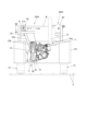
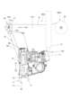
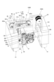
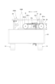
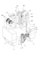
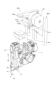
- FIG. 1A is a perspective view showing an example of a binding device according to the first embodiment.
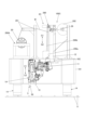
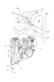
- FIG. 1B is a front view showing an example of the binding device of the first embodiment.
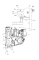
- FIG. 1C is a rear view showing an example of the binding device of the first embodiment.
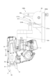
- FIG. 1D is a top view showing an example of the binding device of the first embodiment.
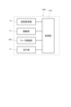
- FIG. 1E is a functional block diagram showing an example of the binding device of the first embodiment.
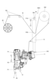
- FIG. 2 is a side view of essential parts showing an example of the internal configuration of the reinforcing bar binding machine of this embodiment.
- FIG. 3A is a cross-sectional plan view showing an example of the binding part.
- FIG. 3B is a cross-sectional plan view showing an example of the binding part.
- FIG. 3A is a cross-sectional plan view showing an example of the binding part.
- FIG. 3B is a cross-sectional plan view showing an example of the binding part.
- FIG. 4A is a front view of main parts showing an example of the operation of the binding device of the first embodiment.
- FIG. 4B is a front view of main parts showing an example of the operation of the binding device of the first embodiment.
- FIG. 4C is a front view of main parts showing an example of the operation of the binding device of the first embodiment.
- FIG. 5A is a perspective view showing an example of a binding device according to the second embodiment.
- FIG. 5B is a front view showing an example of the binding device of the second embodiment.
- FIG. 5C is a rear view showing an example of the binding device of the second embodiment.
- FIG. 5D is a top view showing an example of the binding device of the second embodiment.
- FIG. 5E is a functional block diagram showing an example of a binding device according to the second embodiment.
- FIG. 6A is a front view of main parts showing an example of the operation of the binding device according to the second embodiment.
- FIG. 6B is a front view of main parts showing an example of the operation of the binding device according to the second embodiment.
- FIG. 6C is a front view of main parts showing an example of the operation of the binding device of the second embodiment.
- FIG. 7A is a perspective view showing an example of a binding device according to the third embodiment.
- FIG. 7B is a perspective view showing an example of a binding device according to the third embodiment.
- FIG. 7C is a front view showing an example of the binding device of the third embodiment.
- FIG. 7D is a functional block diagram showing an example of a binding device according to the third embodiment.
- FIG. 7A is a perspective view showing an example of a binding device according to the third embodiment.
- FIG. 7B is a perspective view showing an example of a binding device according to the third embodiment.
- FIG. 7C is a front view showing an example of the binding device
- FIG. 8A is a front view of main parts showing an example of the operation of the binding device according to the third embodiment.
- FIG. 8B is a front view of main parts showing an example of the operation of the binding device according to the third embodiment.
- FIG. 8C is a front view of main parts showing an example of the operation of the binding device according to the third embodiment.
- FIG. 8D is a front view of main parts showing an example of the operation of the binding device according to the third embodiment.
- FIG. 9A is a perspective view showing an example of a brake section.
- FIG. 9B is a perspective view showing an example of a brake section.
- FIG. 9C is a perspective view showing an example of a brake section.
- FIG. 10A is a front view showing an example of a brake section.
- FIG. 10B is a front view showing an example of the braking section.
- FIG. 10C is a front view showing an example of a brake section.
- FIG. 11 is a top view showing another example of the brake
- FIG. 1A is a perspective view showing an example of a binding device according to the first embodiment
- FIG. 1B is a front view showing an example of the binding device according to the first embodiment
- FIG. 1C is a perspective view showing an example of the binding device according to the first embodiment
- FIG. 1D is a rear view showing an example of the binding device of the first embodiment
- FIG. 1D is a top view showing an example of the binding device of the first embodiment.
- FIG. 1E is a functional block diagram showing an example of the binding device of the first embodiment.
- a bundling device 100A of the first embodiment includes a reinforcing bar bundling machine 1A for bundling intersections of reinforcing bars S arranged in a grid with wires W, and a reinforcing bar bundling machine 1A for bundling the intersection points of reinforcing bars S arranged in a lattice shape.
- the binding machine moving unit 10A is provided to move the binding machine between a binding position and a retracted position in a substantially vertical direction intersecting the binding position.
- the binding device 100A includes a wire drawing section 2A that pulls out the wire W from a reel 20 on which the wire W used in the reinforcing bar binding machine 1A is wound, and a reel accommodating section 200A in which the reel 20 is accommodated.
- the bundling device 100A includes a running section 14 that moves the entire bundling device 100A along the reinforcing bars S arrangement surface.
- the binding device 100A has a configuration in which the traveling section 14 moves riding on reinforcing bars S arranged in a grid pattern, and the surface on which the reinforcing bars S are arranged is a substantially horizontal surface.
- the binding device 100A moves by the traveling part 14 so that the reinforcing bar binding machine 1A is aligned with the intersection of the reinforcing bars S to be bound, and the binding machine moving part 10A moves the reinforcing bars After moving the tying machine 1A from the standby position to the tying position, the reinforcing bar tying machine 1A ties the reinforcing bars S with the wires W.
- the tying machine moving unit 10A moves the reinforcing bar tying machine 1A from the bundling position to the standby position. Further, in accordance with the movement of the reinforcing bar tying machine 1A from the tying position to the standby position, the wire drawing unit 2A pulls out the wire W to be used in the next tying operation from the reel 20.
- the binding machine moving part 10A is an example of a binding mechanism moving part, and includes a binding machine mounting part 11 to which the reinforcing bar binding machine 1A is mounted, and a driving part 12 that moves the binding machine mounting part 11 in the vertical direction indicated by arrows C1 and C2. , a connecting portion 13 connected to the wire pull-out portion 2A.
- the drive unit 12 includes a power source, such as a motor or an actuator, whose movement amount, movement direction, movement speed, etc. can be controlled, and the movement (output) of the power source in the direction of arrows C1 and C2 of the binding machine mounting unit 11. Equipped with various mechanisms to convert into
- the tying machine moving section 10A moves the reinforcing bar tying machine 1A mounted on the tying machine mounting section 11 by a predetermined amount in the upward direction indicated by the arrow C1, thereby moving the reinforcing bar tying machine 1A to the retreat position.
- the tying machine moving section 10A moves the reinforcing bar tying machine 1A mounted on the tying machine mounting section 11 by a predetermined amount in the downward direction indicated by arrow C2, thereby moving the reinforcing bar tying machine 1A from the retreat position to the bundling position. .
- the wire drawing section 2A includes a drawing roller 21 provided on a wire W feeding path between the reinforcing bar binding machine 1A and the reel storage section 200A, a roller moving section 22 that moves the drawing roller 21, and a wire W feeding path.
- the route guiding members 23a and 23b are provided to change the direction.
- the pull-out roller 21 is an example of a pull-out member, and is composed of a rotating body that can rotate about a shaft 21a, and the wire W is in contact with the outer peripheral surface.
- the roller moving section 22 moves the drawing roller 21 in the direction of drawing out the wire W from the reel 20 housed in the reel accommodating section 200A and in the direction away from the drawn wire W.
- the roller moving unit 22 moves in the direction of arrow A1, which is the direction in which the pull-out roller 21 leaves the reel accommodating unit 200A and pulls out the wire W from the reel 20 housed in the reel accommodating unit 200A, and the direction in which the pull-out roller 21 moves away from the reel accommodating unit 200A.
- the pull-out roller 21 is reciprocated in the direction of arrow A2, which is the direction approaching the section 200A.
- the directions of arrows A1 and A2 are different from the direction in which the reinforcing bar tying machine 1A moves between the bundling position and the retreat position, and in this example, the wire pull-out section 2A is directed in the direction in which the reinforcing bar tying machine 1A moves.
- the wire W is pulled out in a substantially orthogonal substantially horizontal direction.
- the roller moving unit 22 constitutes a transmitting unit to which the operation of the tying machine moving unit 10A is transmitted and moves the pull-out roller 21 in conjunction with the movement of the reinforcing bar tying machine 1A. Therefore, the roller moving section 22 includes a first link 22a to which the pull-out roller 21 is attached, and a second link 22b connected to the reinforcing bar tying machine 1A via the tying machine moving section 10A.
- the roller moving unit 22 has a first link 22a extending in one direction from the shaft 22c so that the first link 22a and the second link 22b can rotate in conjunction with the shaft 22c as a fulcrum, A second link 22b extends in the other direction from the shaft 22c and is integrally connected.
- the pull-out roller 21 is rotatably attached to the end of the first link 22a opposite to the shaft 22c, with the shaft 21a as a fulcrum.
- the roller moving section 22 includes a connected section 22d connected to the binding machine moving section 10A at the end of the second link 22b opposite to the shaft 22c.
- the connected portion 22d is constituted by a columnar or cylindrical convex portion that protrudes from the second link 22b along the direction in which the shaft 22c extends.
- the connecting part 13 of the tying machine moving part 10A opens with a width slightly larger than the diameter of the connected part 22d of the roller moving part 22, and extends in a direction intersecting the moving direction of the reinforcing bar tying machine 1A.
- the connected portion 22d which is a columnar or cylindrical convex portion, enters the connecting portion 13, which is formed by a groove having a width slightly larger than the diameter of the connected portion 22d, so that the roller can move. 22 and the reinforcing bar tying machine 1A are connected, and the movement of the reinforcing bar tying machine 1A in the directions of arrows C1 and C2 is transmitted to the roller moving part 22.
- the roller moving unit 22 converts the movement of the reinforcing bar binding machine 1A along the vertical direction indicated by arrows C1 and C2 into the movement of the pull-out roller 21 along the horizontal direction indicated by arrows A1 and A2.
- the first link 22a and the second link 22b are connected in an L shape, and the shaft 22c is provided at the intersection of the first link 22a and the second link 22b. .
- the first link 22a forms one side of the L-shaped member, intersects with the moving direction of the pull-out roller 21 shown by arrows A1 and A2, and extends in the moving direction of the reinforcing bar binding machine 1A shown by arrows C1 and C2. It extends from the axis 22c in one direction along the opposite direction.
- the second link 22b forms the other side of the L-shaped member, intersects with the moving direction of the reinforcing bar binding machine 1A shown by arrows C1 and C2, and moves the pull-out roller 21 shown by arrows A1 and A2. It extends from the axis 22c in another direction along the direction.
- the roller moving unit 22 rotates around the shaft 22c of the first link 22a and the second link 22b, and changes the rotation angle of the first link 22a and the second link 22b and the pull-out roller 21 from the shaft 22c.
- the pull-out roller 21 moves along a trajectory along an arc whose length corresponds to the diameter up to the axis 21a.
- roller moving unit 22 rotates the first link 22a and the second link 22b around the shaft 22c as a fulcrum, and changes the rotation angle of the first link 22a and the second link 22b and the rotation angle of the first link 22a and the second link 22b.
- the connected portion 22d moves along a trajectory along an arc having a length corresponding to the diameter up to the connecting portion 22d.
- the roller moving unit 22 operates so that the amount of wire W pulled out by the movement of the pull-out roller 21 is n times (n>1) the amount of movement of the reinforcing bar binding machine 1A connected to the connected portion 22d.
- the length from the shaft 22c to the shaft 21a of the pull-out roller 21 is longer than the length from the shaft 22c to the connected portion 22d.
- the roller moving unit 22 rotates the pull-out roller 21 with the axis 22c of the first link 22a and the second link 22b as a fulcrum in conjunction with the movement of the reinforcing bar binding machine 1A in the direction of the arrow C1.
- the roller moving unit 22 rotates the pull-out roller 21 with the axis 22c of the first link 22a and the second link 22b as a fulcrum in conjunction with the movement of the reinforcing bar binding machine 1A in the direction of the arrow C1.
- By moving it in the A1 direction it is possible to pull out from the reel 20 a length of wire W that exceeds the amount of movement of the reinforcing bar binding machine 1A.
- the roller moving unit 22 moves the pull-out roller 21 from the shaft 22c so that the amount of wire W pulled out by the movement of the pull-out roller 21 is the same as the amount of movement of the reinforcing bar binding machine 1A connected to the connected portion 22d.
- the length to the shaft 21a may be configured to be the same as the length from the shaft 22c to the connected portion 22d. Further, in order to amplify the torque for moving the pull-out roller 21, the length from the shaft 22c to the shaft 21a of the pull-out roller 21 may be configured to be shorter than the length from the shaft 22c to the connected portion 22d.
- the route guiding member 23a is provided in the feeding route of the wire W between the pull-out roller 21 and the reinforcing bar binding machine 1A.
- the route guiding member 23b is provided on the feeding route of the wire W between the route guiding member 23a and the reinforcing bar binding machine 1A.
- the route guiding members 23a and 23b are composed of annular members, and the two wires W are passed through the hole in the center of the annular member, so that the feeding route of the wires W along the horizontal direction is vertically directed. It is bent along the feeding path of the wire W along.
- the wire drawing section 2A is configured to move the drawing roller 21 in order to reduce the load applied to the wire W between the reinforcing bar binding machine 1A and the drawing roller 21 when the drawing roller 21 moves in the direction of arrow A1 to pull out the wire W.
- a one-way rotation regulating mechanism (one-way clutch) 24 may be provided that allows rotation in the direction shown by arrow B1 and restricts rotation in the direction shown by arrow B2.
- the one-way rotation regulating mechanism 24 is realized with a ratchet structure in this example, and is provided with teeth formed along the circumferential direction of the pull-out roller 21 and on the first link 22a side, and is attached in the direction of meshing with the teeth.
- the device includes a claw portion that is biased and engages with the tooth portion.
- the one-way rotation regulating mechanism 24 when a force is applied to rotate the pull-out roller 21 in the direction of arrow B1, the claw portion comes off from the tooth portion, and the pull-out roller 21 becomes rotatable in the direction of arrow B1.
- a force is applied to rotate the pull-out roller 21 in the direction of arrow B2
- the engagement between the claw portion and the tooth portion is maintained, and rotation of the pull-out roller 21 in the direction of arrow B2 is restricted.
- the pull-out roller 21 moves in the direction of the arrow A1 to pull out the wire W
- the force exerted by the wire W between the pull-out roller 21 and the reel 20 is also applied to the pull-out roller 21.
- the direction of rotation of the pull-out roller 21 indicated by arrow B2 is the direction in which the pull-out roller 21 attempts to rotate due to the relative pulling force applied to the pull-out roller 21 by the wire W between the pull-out roller 21 and the reel 20. be.
- the binding device 100A is provided with a recessed portion on one side of the rectangular main body 101, into which a part or all of the reinforcing bar binding machine 1A, the binding machine moving part 10A, and the wire drawing part 2A can fit. Further, in the binding device 100A, a running section 14 is provided on the lower surface of the main body section 101.
- the traveling section 14 includes an endless track driven by a motor (not shown). In the bundling device 100A, an endless track constituting the running section 14 rides on the reinforcing bars S arranged in a lattice pattern, and as the endless track rotates, it moves along the surface on which the reinforcing bars S are arranged.
- the binding device 100A is provided with a reel accommodating portion 200A on the upper surface of the main body portion 101.
- the reel accommodating section 200A when the reinforcing bar binding machine 1A is configured to bind the reinforcing bars S with two wires W, the two reels 20 are arranged along the axial direction with the axis of rotation oriented transversely to the vertical direction. They are rotatably housed side by side on the same axis.
- the reel accommodating section 200A includes a route guiding member 26 that guides the two wires W pulled out from each reel 20 to the pulling roller 21 in a parallel form.
- the route guiding member 26 is provided on the feeding route of the wire W between the reel accommodating portion 200A and the pull-out roller 21.
- the route guiding member 26 is composed of an annular member, and two wires W are passed through a hole in the center of the annular member.
- the wire W is wound radially overlappingly while changing its position along the axial direction of a hub (not shown) of the reel 20. Therefore, when the wire W is pulled out from the reel 20, the position at which the wire W is pulled out changes along the axial direction of the reel 20. Furthermore, the position from which the wire W is pulled out changes along the radial direction of the reel 20 depending on the amount of wire W used. As a result, the direction in which the wire W is introduced into the route guiding member 26 changes as the wire W is pulled out from the reel 20 . However, since the portion of the route guiding member 26 that is in contact with the wire W is a curved surface, an increase in resistance due to friction is suppressed.
- the drive unit 12 of the binding machine moving unit 10A, the running unit 14, and the reinforcing bar binding machine 1A are controlled by a control unit 110A.
- the movement of the reinforcing bar tying machine 1A by the tying machine moving part 10A is transmitted to the roller moving part 22, and the pull-out roller 21 moves the wire W by the movement of the roller moving part 22 in accordance with the movement of the reinforcing bar tying machine 1A. bring out. Therefore, the control section 110A controls the wire drawing section 2A by controlling the drive section 12 of the binding machine moving section 10A.
- FIG. 2 is a side view of essential parts showing an example of the internal configuration of the reinforcing bar binding machine of this embodiment.
- the reinforcing bar binding machine 1A is an example of a bundling mechanism, in which the wire W is sent in the positive direction indicated by the arrow F, is wound around two crossed reinforcing bars S that are objects to be tied, and is wound around the reinforcing bars S. After the wire W is sent in the opposite direction indicated by the arrow R and wound around the reinforcing bar S, the wire W is twisted and the reinforcing bar S is bound with the wire W.
- the wire W a wire made of a metal wire that can be plastically deformed, a wire made of a metal wire coated with a resin, a wire of a stranded wire, or the like is used.
- the reinforcing bar binding machine 1A includes a wire feeding section 3 that feeds the wire W in the forward and reverse directions, and a wire guide 4 that guides the wire W sent to the wire feeding section 3.
- the reinforcing bar binding machine 1A also includes a curl forming section 5 that forms a path for winding the wire W sent by the wire feeding section 3 around the reinforcing bars S, and a cutting section 6 that cuts the wire W wound around the reinforcing bars S. Be prepared.
- the reinforcing bar binding machine 1A includes a binding part 7 that twists the wire W wound around the reinforcing bar S, and a drive part 8 that drives the binding part 7.
- the reinforcing bar binding machine 1A includes a wire feeding section 3, a wire guide 4, a cutting section 6, a binding section 7, and a driving section 8 inside a main body section 15 covered with an exterior having a predetermined shape. Further, a curl forming portion 5 is provided to protrude from the main body portion 15 .
- the reinforcing bar tying machine 1A is used in the tying device 100A, it is used with the curl forming part 5 facing downward.
- the side where the curl forming part 5 is provided will be referred to as the lower side.
- the wire feeding section 3 includes a pair of feeding gears 30 that sandwich and feed one or more wires W arranged in parallel.
- a pair of feed gears 30 are urged in a direction toward each other, and the rotational operation of a feed motor (not shown) is transmitted to rotate the feed gears 30.
- the wire feeding section 3 feeds the wire W held between the pair of feeding gears 30 along the extending direction of the wire W.
- the two wires W are sent in parallel.
- the wire guides 4 are provided at predetermined positions upstream and downstream of the wire feeding section 3 with respect to the forward feeding direction of the wire W shown by the arrow F. In addition, in FIG. 2, the wire guide 4 provided on the upstream side of the wire feeding section 3 is not shown.
- the wire guide 4 is provided with an opening extending along the feeding direction of the wire W, and the opening area of the opening on the downstream side is smaller than that of the opening on the upstream side along the forward feeding direction of the wire W.
- the wire guide 4 is configured with a tapered opening having the largest opening area on the introduction side for the wire W sent in the forward direction, and the opening area gradually decreasing from there. Thereby, the wire guide 4 guides the wire W, which is sent in the forward direction and passes through the wire guide 4, between the pair of feed gears 30 and to the cutting section 6.
- the wire guide 4 has an opening on the downstream side along the forward feeding direction of the wires W, which is in the radial direction of the two wires W. It has a shape that regulates the direction. Thereby, the wire guide 4 arranges the two wires W that are sent in the forward direction and passes through the wire guide 4 in parallel along the direction in which the pair of feed gears 30 are lined up, and cuts the wires between the pair of feed gears 30. Guide to part 6.
- the curl forming section 5 includes a curl guide 50 that imparts a curl to the wire W fed by the wire feed section 3, and a guide guide 51 that guides the wire W curled by the curl guide 50 to the binding section 7.
- the curl forming section 5 is provided with a curl guide 50 and a guide guide 51 exposed from the main body section 10.
- the feeding route of the wire W sent by the wire feeding part 3 is regulated by the curl forming part 5, so that the trajectory of the wire W becomes a loop Ru as shown by the broken line in FIG. It is wrapped around the reinforcing bar S.
- the curl forming section 5 includes a guide member 53a and a guide member 53b that guide the wire W sent in the forward direction and give the wire W a curl.
- the guide member 53a is provided in the curl guide 50 on the introduction side of the wire W fed by the wire feeding section 3, and is arranged inside the loop Ru formed by the wire W fed by the wire feeding section 3 in the radial direction.
- the guide member 53b is provided in the curl guide 50 on the side of the discharge section of the wire W sent by the wire feeding section 3, and is arranged on the outside of the loop Ru formed by the wire W in the radial direction.
- the curl forming section 5 includes a guide member moving mechanism 54 that retracts the guide member 53a. After the wire W is wound around the reinforcing bar S, the guide member moving mechanism 54 retracts the guide member 53a in conjunction with the operation of the binding section 7.
- the cutting part 6 includes a fixed blade part 60, a movable blade part 61 that cuts the wire W in cooperation with the fixed blade part 60, and a transmission mechanism 62 that transmits the operation of the binding part 7 to the movable blade part 61.
- the cutting section 6 cuts the wire W by rotating the movable blade section 61 with the fixed blade section 60 as a fulcrum axis.
- the transmission mechanism 62 transmits the operation of the binding section 7 to the movable blade section 61 via the transmission member 75, rotates the movable blade section 61 in conjunction with the operation of the binding section 7, and cuts the wire W.
- the binding section 7 includes a wire locking body 70 to which the wire W is locked, and a sleeve 71 that operates the wire locking body 70.
- the detailed configuration of the binding section 7 will be described later.
- the drive unit 8 includes a motor 80 and a reducer 81 that performs deceleration and torque amplification.
- the main body 15 When the reinforcing bar binding machine 1A is used in a form that is held in the hand by an operator, the main body 15 includes a handle 16, and a battery 17 is removably attached to the handle 16.
- the handle portion 16 of the reinforcing bar tying machine 1A is attached to the tying machine mounting section 11 of the tying machine moving section 10A.
- the reinforcing bar binding machine 1A has a feed regulating part in which the tip of the wire W is brought into contact with the feeding path of the wire W which is sent in the forward direction by the wire feeding part 3, passes through the curl forming part 5, and is wound around the reinforcing bar S. 90.
- the reinforcing bar binding machine 1A has an abutting portion where the reinforcing bar S inserted between the curl guide 50 and the guide guide 51 is abutted against the end of the main body portion 15 between the curl guide 50 and the guide guide 51. 91 (see FIG. 1B).
- the reinforcing bars S are inserted between the curl guide 50 and the guide guide 51, and the reinforcing bar S is inserted between the curl guide 50 and the guide guide. 51 is abutted against the abutting portion 91.
- FIGS. 3A and 3B are cross-sectional plan views showing an example of a binding section. Next, the configuration of the binding section will be described with reference to each figure.
- the binding section 7 includes a rotating shaft 72 that operates the wire locking body 70 and the sleeve 71.
- a rotating shaft 72 and a motor 80 are connected via a reducer 81, and the rotating shaft 72 is driven by the motor 80 via the reducer 81.
- the wire locking body 70 includes a center hook 70C connected to the rotating shaft 72, and a first side hook 70R and a second side hook 70L that open and close with respect to the center hook 70C.
- the center hook 70C is attached to the tip of the rotating shaft 72, which is one end along the axial direction of the rotating shaft 72, and is rotatable relative to the rotating shaft 72 and movable in the axial direction integrally with the rotating shaft 72. are connected through possible configurations.
- the wire locking body 70 opens and closes in a direction in which the tip side of the first side hook 70R approaches and separates from the center hook 70C by a rotational movement about the shaft 71b. Moreover, the tip side of the second side hook 70L opens and closes in the direction of coming into contact with and separating from the center hook 70C.
- the sleeve 71 has a convex portion (not shown) that protrudes from the inner circumferential surface of the space into which the rotary shaft 72 is inserted, and this convex portion engages a feed screw 72a formed along the axial direction on the outer circumference of the rotary shaft 72. Enter the groove.
- the sleeve 71 moves in the rotational direction of the rotating shaft 72 in the vertical direction along the axial direction of the rotating shaft 72 due to the action of a convex portion (not shown) and the feed screw 72a of the rotating shaft 72. Move accordingly. Further, the sleeve 71 rotates integrally with the rotating shaft 72.
- the sleeve 71 includes an opening/closing pin 71a that opens and closes the first side hook 70R and the second side hook 70L.
- the opening/closing pin 71a is inserted into the opening/closing guide hole 73 provided in the first side hook 70R and the second side hook 70L.
- the opening/closing guide hole 73 extends along the moving direction of the sleeve 71, and guides the linear movement of the opening/closing pin 71a, which moves in conjunction with the sleeve 71, through a first side hook 70R and a first side hook 70R with a shaft 71b as a fulcrum. It has a shape that converts into an opening/closing operation by rotation of the second side hook 70L.
- the first side hook 70R and the second side hook 70L are moved by the locus of the opening/closing pin 71a and the shape of the opening/closing guide hole 73. , moves in a direction away from the center hook 70C by a rotational movement about the shaft 71b as a fulcrum.
- first side hook 70R and the second side hook 70L open with respect to the center hook 70C, and between the first side hook 70R and the center hook 70C, the second side hook 70L and the center hook 70C A feeding path through which the wire W passes is formed between the two.
- the wire W fed by the wire feeding section 3 passes between the center hook 70C and the first side hook 70R. Pass.
- the wire W passing between the center hook 70C and the first side hook 70R is guided to the curl forming part 5.
- the wire W, which has been curled in the curl forming part 5 and guided to the binding part 7, passes between the center hook 70C and the second side hook 70L.
- the first side hook 70R and the second side hook 70L are moved by the locus of the opening/closing pin 71a and the shape of the opening/closing guide hole 73. , moves in a direction approaching the center hook 70C by a rotational movement using the shaft 71b as a fulcrum. Thereby, the first side hook 70R and the second side hook 70L close to the center hook 70C.
- the wire W sandwiched between the first side hook 70R and the center hook 70C moves between the first side hook 70R and the center hook 70C. It is locked in a form that allows it to be moved. Further, when the second side hook 70L closes to the center hook 70C, the wire W sandwiched between the second side hook 70L and the center hook 70C is connected to the second side hook 70L and the center hook 70C. It is locked in such a way that it cannot be slipped out from between.
- the sleeve 71 has a bending part 71c1 that shapes the wire W into a predetermined shape by pushing and bending one end of the wire W in a predetermined direction, and the other end of the wire W cut by the cutting part 6.
- a bending portion 71c2 is provided that shapes the wire W into a predetermined shape by pushing and bending the terminal end side, which is the end portion, in a predetermined direction.
- the sleeve 71 pushes the tip side of the wire W, which is locked by the center hook 70C and the second side hook 70L, with the bending part 71c1, and bends it toward the reinforcing bar S side. Furthermore, by moving downward as indicated by the arrow D1, the sleeve 71 is locked by the center hook 70C and the first side hook 70R, and the terminal end side of the wire W cut by the cutting part 6 is bent by the bending part 71c2. Push it and bend it towards the reinforcing bar S side.
- the binding section 7 includes a rotation regulating section 74 that regulates the rotation of the wire locking body 70 and the sleeve 71 in conjunction with the rotational movement of the rotating shaft 72.
- the rotation regulating part 74 regulates the rotation of the sleeve 71 in conjunction with the rotation of the rotating shaft 72, depending on the position of the sleeve 71 along the axial direction of the rotating shaft 72.
- the sleeve 71 moves in the direction of arrow D1 and the direction of arrow D2 by the rotational operation.
- the sleeve 71 moves in the direction of the arrow D1 without rotating, so that the first side hook 70R and the second side hook 70L close to the center hook 70C, and the wire W is locked. Further, by moving the sleeve 71 in the direction of arrow D2 without rotating, the first side hook 70R and the second side hook 70L open with respect to the center hook 70C, and the wire W is unlocked. .
- first side hook 70R, second side hook 70L, and center hook 70C that have locked the wire W rotate, and the locked wire W is twisted.
- ⁇ Operation example of the binding device of the first embodiment> 4A, 4B, and 4C are main part front views showing an example of the operation of the tying device of the first embodiment. Referring to each figure, the wire W is pulled out from the reel 20, An example of the operation of the binding device 100A that makes the wire W usable will now be described.
- the reinforcing bar bundling machine 1A moves to the bundling position P1, as shown in FIG. 4A.
- the reinforcing bar binding machine 1A moves in the direction of arrow C2 from the retreat position P2 shown in FIG. 4B to the binding position P1 shown in FIG. Move in direction A2.
- the binding device 100A is configured such that the pulling roller 21, which has moved to the standby position P10, is separated from the wire W pulled out from the reel 20 when the binding operation is completed by the reinforcing bar binding machine 1A.
- a relationship is set between the amount of wire W used in the binding operation and the amount of wire W pulled out, which will be described later.
- the control unit 110A controls the drive unit 12 of the binding machine moving unit 10A to move the reinforcing bar binding machine 1A from the binding position P1 to the retreat position P2 in the direction indicated by the arrow C1. move in the direction.
- the roller moving unit 22 when the reinforcing bar binding machine 1A moves in the direction of arrow C1, the side of the first link 22a on which the pull-out roller 21 is provided moves in the direction of arrow A1.
- the roller moving unit 22 moves the pull-out roller from the shaft 22c so that the amount of wire W pulled out by the movement of the pull-out roller 21 is a predetermined n times (n>1) the amount of movement of the reinforcing bar binding machine 1A. 21 to the shaft 21a and the length from the shaft 22c to the connected portion 22d may be set.
- the amount of wire W pulled out due to the movement of the pull-out roller 21 from the standby position P10 to the pull-out position P20 is multiplied by a predetermined value, e.g. It is possible to increase the number of wires by about 3 times, and to draw out the necessary amount of wire W from the reel 20 in the next binding operation.
- a predetermined value e.g. It is possible to increase the number of wires by about 3 times, and to draw out the necessary amount of wire W from the reel 20 in the next binding operation.
- this wire W pulling operation there is no need to adjust the amount of movement of the reinforcing bar tying machine 1A to the amount of pulling out of the wire W required for the next tying operation, and the amount of movement of the reinforcing bar tying machine 1A can be reduced.
- the size can be reduced to 100A.
- the tying device 100A When the tying device 100A starts the next tying operation after the wire W drawing operation linked to the movement of the reinforcing bar tying machine 1A is completed, the tying device 100A first moves the reinforcing bar tying machine 1A from the retreat position P2 to the tying position P1 in the direction of arrow C2. move in the direction. In the roller moving unit 22, when the reinforcing bar binding machine 1A moves in the direction of arrow C2, the side of the first link 22a on which the pull-out roller 21 is provided moves in the direction of arrow A2.
- the reinforcing bar binding machine 1A sends the wire W in the forward direction using the wire feeding section 3, winds it around the two crossed reinforcing bars S, and wraps the wire W wound around the reinforcing bars S. is sent in the opposite direction by the wire feeding section 3 and wound around the reinforcing bars S, and then the wires W are twisted and the reinforcing bars S are tied together with the wires W. For this reason, when the wire W is sent in the forward direction by the wire feeding section 3, the wire W is sent from the reel 20 so that the wire W does not come in contact with the pull-out roller 21 that is moving to the standby position P10. The withdrawal amount is set.
- the reel 20 on which the wire W is wound is made larger than the reel of a size that can be loaded into the conventional reinforcing bar binding machine 1A to increase the capacity of the wire W.
- the wire drawing section 2A of the bundling device 100A is configured to move the drawing roller 21 using the force of moving the reinforcing bar bundling machine 1A to pull out the wire W.
- the force for pulling out the wire W is strong compared to the above.
- the wire W is fed in the forward direction by the wire feeding unit 3, the wire W is fed from the reel 20 with a surplus amount that does not touch the pull-out roller 21 that is moving to the standby position P10.
- the withdrawal amount is set. Thereby, it is not necessary to pull out the wire W from the reel 20 with the wire feeding section 3 of the reinforcing bar binding machine 1A, and it is possible to prevent the amount of the wire W from being drawn out insufficiently.
- the wire feeding section 3 can reliably feed the amount of wire W required to wind around the two intersecting reinforcing bars S.
- the wire W wound around the reinforcing bar S in the opposite direction indicated by the arrow R and wrapping it around the reinforcing bar S, insufficient length of the wire W is suppressed, and the reinforcing bar S is securely attached to the reinforcing bar S.
- the wire W can be wound around.
- the control unit 110A can detect the load applied to the drive unit 12 when moving the pull-out roller 21 to pull out the wire W. Therefore, if the load when pulling out the wire W is higher than the specified value, the control unit 110A determines that a sufficient amount of wire W cannot be pulled out from the reel 20, and evacuates the reinforcing bar binding machine 1A from the binding position P1. During the movement to the position P2, the movement of the reinforcing bar binding machine 1A by the drive unit 12 may be stopped and an alarm may be issued.
- the unit 110A may be configured to be able to calculate the remaining amount of the wire W wound around the reel 20 based on the load applied to the drive unit 12.
- FIG. 5A is a perspective view showing an example of a binding device according to the second embodiment
- FIG. 5B is a front view showing an example of the binding device according to the second embodiment
- FIG. 5C is a perspective view showing an example of the binding device according to the second embodiment
- FIG. 5D is a rear view showing an example of the binding device of the second embodiment
- FIG. 5D is a top view showing an example of the binding device of the second embodiment.
- FIG. 5E is a functional block diagram showing an example of the binding device of the second embodiment.
- a bundling device 100B of the second embodiment includes a reinforcing bar bundling machine 1A for bundling intersections of reinforcing bars S arranged in a grid with wires W, and a reinforcing bar bundling machine 1A between a bundling position and a retreat position.
- a binding machine moving section 10B is provided.
- the binding device 100B includes a wire drawing part 2B that draws out the wire W from a reel 20 on which the wire W used in the reinforcing bar binding machine 1A is wound, and a reel accommodating part 200A in which the reel 20 is stored.
- the bundling device 100B includes a running section 14 that moves the entire bundling device 100B along the reinforcing bars S arrangement surface.
- the binding machine moving part 10B is an example of a binding mechanism moving part, and includes a binding machine mounting part 11 to which the reinforcing bar binding machine 1A is mounted, and a driving part 12 that moves the binding machine mounting part 11 in the vertical direction indicated by arrows C1 and C2. , a connecting portion 13B connected to the wire pull-out portion 2B.
- the drive unit 12 includes a power source, such as a motor or an actuator, whose movement amount, movement direction, movement speed, etc. can be controlled, and the movement (output) of the power source in the direction of arrows C1 and C2 of the binding machine mounting unit 11. Equipped with various mechanisms to convert into
- the tying machine moving section 10B moves the reinforcing bar tying machine 1A mounted on the tying machine mounting section 11 by a predetermined amount in the upward direction indicated by the arrow C1, thereby moving the reinforcing bar tying machine 1A to the retreat position. Furthermore, the bundling machine moving section 10B moves the reinforcing bar bundling machine 1A mounted on the bundling machine mounting section 11 by a predetermined amount in the downward direction indicated by arrow C2, thereby moving the reinforcing bar bundling machine 1A from the retreat position to the bundling position. .
- the wire drawing section 2B includes a drawing roller 27 provided on the wire W feeding path between the reinforcing bar binding machine 1A and the reel accommodating section 200A, a roller moving section 28 that moves the drawing roller 27, and a wire W feeding path.
- the route guiding members 23a and 23b are provided to change the direction.
- the pull-out roller 27 is an example of a pull-out member, and is composed of a rotating body that can rotate about a shaft 27a, and the wire W is in contact with the outer peripheral surface.
- the roller moving section 28 moves the drawing roller 27 in the direction of drawing out the wire W from the reel 20 housed in the reel accommodating section 200A and in the direction away from the drawn wire W.
- the roller moving unit 28 moves in the arrow A1 direction, which is the direction in which the pull-out roller 27 leaves the reel accommodating unit 200A and pulls out the wire W from the reel 20 housed in the reel accommodating unit 200A, and the direction in which the pull-out roller 27 moves away from the reel accommodating unit 200A.
- the pull-out roller 27 is reciprocated in the direction of arrow A2, which is the direction approaching the section 200A.
- the roller moving unit 28 constitutes a transmitting unit to which the operation of the tying machine moving unit 10B is transmitted and moves the pull-out roller 27 in conjunction with the movement of the reinforcing bar tying machine 1A. Therefore, the roller moving section 28 includes a first belt section 281 connected to the pull-out roller 27 and a second belt section 282 connected to the reinforcing bar binding machine 1A via the binding machine moving section 10B.
- the first belt portion 281 includes a pair of rotatable pulleys 281a, 281b and a first belt 281c stretched between the pair of pulleys 281a, 281b.
- the first belt portion 281 is provided with a pulley 281a on one side along the arrow A1 and A2 directions, and a pulley 281b on the other side, and is oriented such that it can run along the arrow A1 and A2 directions. , the first belt 281c is stretched.
- the second belt portion 282 includes four rotatable pulleys 282a, 282b, 282c, and 282d, and a second belt 282e that is stretched between the four pulleys 282a, 282b, 282c, and 282d.
- the second belt portion 282 is provided with a pulley 282a on one side along the arrows A1 and A2, and a pulley 282b on the lower side, which is one side along the arrows C1 and C2. Further, the second belt portion 282 is provided with a pulley 282c on the upper side, which is the other side along the arrows A1 and A2 directions, and the other side along the arrows C1 and C2 directions, and is opposite to the pulley 282c.
- a pulley 282d is provided.
- the second belt portion 282 is oriented so that it can run along the arrow C1 and C2 directions between the pulley 282b and the pulley 282c, and is oriented so that it can run along the arrow A1 and A2 directions between the pulley 282a and the pulley 282c.
- the second belt 282e is stretched in an orientation that allows the vehicle to run.
- a pulley 281a of the first belt section 281 and a pulley 282a of the second belt section 282 are provided coaxially, and the pulley 281a rotates in synchronization with the rotation of the pulley 282a.
- the support section 27b of the pull-out roller 27 is connected to a portion of the first belt 281c of the first belt section 281 that runs in the directions of arrows A1 and A2.
- the connecting section 13B of the binding machine moving section 10B is connected to a portion of the second belt 282e of the second belt section 282 that runs in the directions of arrows C1 and C2.
- the binding machine moving section 10B moves the reinforcing bar binding machine 1A in the direction of arrow C1
- the binding machine mounting section 11 is connected to the second belt 282e of the second belt section 282.
- the part travels in the direction of arrow C1, each pulley around which the second belt 282e is stretched rotates, and the pulley 282a of the second belt portion 282 rotates in the direction of arrow E1.
- the pull-out roller 27 separates from the reel accommodating part 200A, and the wire W is removed from the reel 20 housed in the reel accommodating part 200A. Move from the standby position to the pull-out position in the direction of arrow A1.
- the binding machine moving section 10B moves the reinforcing bar binding machine 1A in the direction of arrow C2
- the binding machine mounting section 11 is connected to the second belt 282e of the second belt section 282. travels in the direction of arrow C2, each pulley around which the second belt 282e is stretched rotates, and the pulley 282a of the second belt portion 282 rotates in the direction of arrow E2.
- the pull-out roller 27 approaches the reel accommodating section 200A and moves away from the wire W pulled out from the reel 20 in the direction of arrow A2. , move from the drawn position to the standby position.
- the pull-out roller 27 moves in the direction of arrow A2 and approaches the reel accommodating portion 200A.
- the pull-out roller 27 moves from the pull-out position to the standby position in the direction of arrow A2, away from the apex of the wire W pulled out from the reel 20 in the direction of arrow A1.
- the roller moving unit 28 rotates with the movement of the reinforcing bar tying machine 1A so that the amount of wire W pulled out by the movement of the drawing roller 21 is n times (n>1) the amount of movement of the reinforcing bar tying machine 1A.
- the roller moving unit 28 moves the pull-out roller 27 in the direction of arrow A1 by the rotational operation of the pulley 281a in conjunction with the movement of the reinforcing bar binding machine 1A in the direction of arrow C1, exceeding the amount of movement of the reinforcing bar binding machine 1A.
- the length of wire W can be pulled out from the reel 20.
- the roller moving section 22 moves the second belt section 282 so that the amount of wire W pulled out by the movement of the drawing roller 21 is the same as the amount of movement of the reinforcing bar binding machine 1A connected to the connected section 22d.
- the pulley 282a and the pulley 281a of the first belt portion 281 may have the same diameter. Further, in order to amplify the torque for moving the pull-out roller 21, the pulley 282a of the second belt section 282 may have a larger diameter than the pulley 281a of the first belt section 281.
- the drive unit 12 of the binding machine moving unit 10B, the traveling unit 14, and the reinforcing bar binding machine 1A are controlled by a control unit 110B.
- the control section 110B controls the wire drawing section 2B by controlling the drive section 12 of the binding machine moving section 10B.
- 6A, 6B, and 6C are main part front views showing an example of the operation of the binding device of the second embodiment. Referring to each figure, the wire W is pulled out from the reel 20, An example of the operation of the binding device 100B that makes the wire W usable will now be described.
- the reinforcing bar bundling machine 1A moves to the bundling position P1, as shown in FIG. 6A.
- the reinforcing bar binding machine 1A moves in the direction of arrow C2 from the retracted position P2 shown in FIG. 6B to the binding position P1 shown in FIG.
- the part to which the machine mounting part 11 is connected runs in the direction of arrow C2, and the pulley 282a around which the second belt 282e is stretched rotates in the direction of arrow E2.
- the pull-out roller 27 approaches the reel accommodating section 200A and moves away from the wire W pulled out from the reel 20 in the direction of arrow A2. do. Then, when the reinforcing bar binding machine 1A is moving to the binding position P1, the pull-out roller 27 is moved to a standby position P10 away from the wire W pulled out from the reel 20. In other words, when the reinforcing bar binding machine 1A moves in the direction of arrow C2 from the retreat position P2 to the binding position P1, the pull-out roller 27 moves in the direction of arrow A2 and approaches the reel accommodating portion 200A. As a result, the pull-out roller 27 separates from the apex portion of the wire W pulled out from the reel 20 in the direction of arrow A1.
- the control section 110B controls the drive section 12 of the bundling machine moving section 10B to move the reinforcing bar bundling machine 1A from the bundling position P1 to the retreat position P2 in the direction of arrow C1. move in the direction.
- the roller moving unit 28 when the reinforcing bar binding machine 1A moves in the direction of the arrow C1, the part of the second belt 282e of the second belt part 282 to which the binding machine attachment part 11 is connected runs in the direction of the arrow C1, Pulley 282a, on which second belt 282e is suspended, rotates in the direction of arrow E1.
- the roller moving unit 28 moves the second belt unit so that the amount of wire W pulled out by the movement of the pull-out roller 21 is a predetermined n times (n>1) the amount of movement of the reinforcing bar binding machine 1A.
- the pulley 281a of the first belt portion 281 may have a larger diameter than the pulley 282a of the belt 282.
- the amount of wire W drawn out by the movement of the drawing roller 27 from the standby position P10 to the drawing position P20 is multiplied by a predetermined value, for example, with respect to the amount of movement of the reinforcing bar binding machine 1A from the bundling position P1 to the retreat position P2. It is possible to increase the number of wires by about 3 times, and to draw out the necessary amount of wire W from the reel 20 in the next binding operation. With this wire W pulling operation, there is no need to adjust the amount of movement of the reinforcing bar tying machine 1A to the amount of pulling out of the wire W required for the next tying operation, and the amount of movement of the reinforcing bar tying machine 1A can be reduced. The size can be reduced to 100B.
- the tying device 100B When the tying device 100B starts the next tying operation after the wire W drawing operation linked to the movement of the reinforcing bar tying machine 1A is completed, the tying device 100B first moves the reinforcing bar tying machine 1A from the retreat position P2 to the tying position P1 in the direction of arrow C2. move in the direction.
- the roller moving part 28 when the reinforcing bar binding machine 1A moves in the direction of arrow C2, the part of the second belt 282e of the second belt part 282 to which the binding machine mounting part 11 is connected runs in the direction of arrow C2,
- the wire feeding section 3 can reliably feed the amount of wire W required to wind around the two intersecting reinforcing bars S.
- the wire W wound around the reinforcing bar S in the opposite direction indicated by the arrow R and wrapping it around the reinforcing bar S, insufficient length of the wire W is suppressed, and the reinforcing bar S is securely attached to the reinforcing bar S.
- the wire W can be wound around.
- the control unit 110B can detect the load applied to the drive unit 12 when moving the pull-out roller 27 to pull out the wire W. Therefore, if the load when pulling out the wire W is higher than the specified value, the control unit 110B determines that a sufficient amount of wire W cannot be pulled out from the reel 20, and evacuates the reinforcing bar binding machine 1A from the binding position P1. During the movement to the position P2, the movement of the reinforcing bar binding machine 1A by the drive unit 12 may be stopped and an alarm may be issued.
- control unit 110B may be configured to be able to calculate the remaining amount of the wire W wound around the reel 20 based on the load applied to the drive unit 12.
- FIG. 7A and 7B are perspective views showing an example of the binding device of the third embodiment
- FIG. 7C is a front view showing an example of the binding device of the third embodiment
- FIG. 7D is a functional block diagram showing an example of the binding device of the third embodiment.
- a bundling device 100C includes a reinforcing bar bundling machine 1A for bundling intersections of reinforcing bars S arranged in a grid shape with wires W, and a reinforcing bar bundling machine 1A between a bundling position and a retreat position.
- a binding machine moving section 10C is provided.
- the binding device 100C includes a wire pull-out section 2C for pulling out the wire W from the reel 20 on which the wire W used in the reinforcing bar binding machine 1A is wound, and a reel accommodating section 200A in which the reel 20 is accommodated.
- the bundling device 100C includes a running section 14 that moves the entire bundling device 100C along the reinforcing bars S arrangement surface.
- the binding machine moving part 10C is an example of a binding mechanism moving part, and includes a binding machine mounting part 11 to which the reinforcing bar binding machine 1A is mounted, and a driving part 12 that moves the binding machine mounting part 11 in the vertical direction indicated by arrows C1 and C2. Be prepared.
- the drive unit 12 includes a power source, such as a motor or an actuator, whose movement amount, movement direction, movement speed, etc. can be controlled, and the movement (output) of the power source in the direction of arrows C1 and C2 of the binding machine mounting unit 11. Equipped with various mechanisms to convert into
- the tying machine moving section 10C moves the reinforcing bar tying machine 1A mounted on the tying machine mounting section 11 by a predetermined amount in the upward direction indicated by the arrow C1, thereby moving the reinforcing bar tying machine 1A to the retreat position. Furthermore, the bundling machine moving section 10B moves the reinforcing bar bundling machine 1A mounted on the bundling machine mounting section 11 by a predetermined amount in the downward direction indicated by arrow C2, thereby moving the reinforcing bar bundling machine 1A from the retreat position to the bundling position. .
- the wire drawing section 2C includes a drawing roller 29 provided on the wire W feeding path between the reinforcing bar binding machine 1A and the reel accommodating section 200A, and a roller moving section 290 that moves the drawing roller 29.
- the wire drawing section 2C also includes a first wire guiding section 291 that guides the wire W between the drawing roller 29 and the reel 20, and a first wire guiding section 291 that guides the wire W between the drawing roller 29 and the reinforcing bar binding machine 1A. 2 wire guide portions 292. Further, the wire drawing section 2C includes route guiding members 23c and 23d that change the route along which the wire W is sent.
- the pull-out roller 29 is an example of a pull-out member, and is composed of a rotating body that can rotate around a shaft 29a, and the wire W is in contact with the outer peripheral surface.
- the pull-out roller 29 is provided between the first wire guide section 291 and the second wire guide section 292.
- the roller moving unit 290 includes a drive mechanism including a motor 290a and a belt 290b, and moves the pull-out roller 29 to the wire W between the first wire guiding unit 291 and the second wire guiding unit 292. It is moved in the directions of arrows G1 and G2 which intersect with each other.
- the roller moving unit 290 is driven by the motor 290a to move the pull-out roller 29 from the standby position to the pull-out position in the direction of arrow G1 in which the wire W guided by the first wire guide unit 291 is pulled out from the reel 20. Further, the roller moving unit 290 moves the pull-out roller 29 from the pull-out position to the standby position in the direction of arrow G2 away from the wire W pulled out from the reel 20 by driving the motor 290a.
- the first wire guide section 291 is composed of a rotary body that can rotate about an axis, and the wire W is in contact with the outer circumferential surface of the first wire guide section 291, and rotates when the wire W is fed.
- the first wire guide section 291 is arranged so that when the pull-out roller 29 moves in the direction of arrow G1 to pull out the wire W from the reel 20, a force is applied to the wire W in the direction in which the wire W is pulled out from the reel 20. induce.
- the second wire guide section 292 is composed of a rotary body that can rotate about an axis, and the wire W is in contact with the outer circumferential surface of the second wire guide section 292, and the second wire guide section 292 rotates when the wire W is fed.
- the wire drawing part 2C moves the wire W between the reel 20 and the first wire guiding part 291, and the reinforcing bar binding machine 1A and the second wire guiding part by moving the drawing roller 29 from the standby position to the pulling position. 292 , a pulling force is applied between the first wire guide section 291 and the second wire guide section 292 .
- the first wire guiding part 291 side It is switched whether the wire W on the side of the second wire guide section 292 is sent or the wire W on the second wire guiding section 292 side is sent.
- the surplus wire W generated when the reinforcing bar binding machine 1A sends the wire W in the opposite direction and winds it around the reinforcing bar S is absorbed, and the wire W is pulled out from the reel 20 housed in the reel accommodating section 200A.
- the route guide members 23c and 23d are provided on the wire W feeding route between the second wire guide section 292 and the reinforcing bar binding machine 1A.
- the route guide members 23c and 23d are composed of annular members, and the two wires W are passed through the hole in the center of the annular member, so that the feeding route of the wires W along the horizontal direction is vertically directed. It is bent along the feeding path of the wire W along. Since the portions of the route guide members 23c and 23d that are in contact with the wires W are curved surfaces, an increase in resistance due to friction is suppressed.
- the drive unit 12 of the binding machine moving unit 10C, the motor 290a of the roller moving unit 290, the traveling unit 14, and the reinforcing bar binding machine 1A are controlled by a control unit 110C.
- the control section 110C controls the drive section 12 of the tying machine moving section 10C, and controls the motor 290a of the roller moving section 290 to operate the wire drawing section 2B in accordance with the timing of moving the reinforcing bar tying machine 1A.
- the wire pulling section 2C pulls out the wire W at a timing when the reinforcing bars S are not tied by the reinforcing bar binding machine 1A.
- FIG. 8B, FIG. 8C, and FIG. 8D are main part front views showing an example of the operation of the binding device of the third embodiment.
- An example of the operation of the binding device 100C that allows the wire W to be used in the binding machine 1A will be described.
- the reinforcing bar bundling machine 1A moves to the bundling position P1, as shown in FIG. 8A.
- the wire drawing unit 2C moves the drawing roller 29 from the drawing position P20 to the standby position P10 in the direction of arrow G2 by driving the motor 290a.
- the pull-out roller 29 is moved to the standby position P10 away from the wire W pulled out from the reel 20, as will be described later.
- the control section 110C controls the drive section 12 of the tying machine moving section 10C to move the reinforcing bar tying machine 1A from the tying position P1 as shown in FIG. 8B. It is moved in the direction of arrow C1 to the retreat position P2. Further, when the binding operation is completed in the reinforcing bar binding machine 1A, the control unit 110C controls the motor 290a of the roller moving unit 290, and as shown in FIG. 8C, the wire pulling unit 2C is driven by the pulling roller 29 is moved in the direction of arrow G1 in which the wire W guided by the first wire guide section 291 is pulled out from the reel 20.
- the pull-out roller 29 is moved to the pull-out position P20 where the wire W is pulled out from the reel 20. Further, in the roller moving unit 290, the amount of movement of the pull-out roller 29 is set so that the necessary amount of wire W can be pulled out from the reel 20 in the next binding operation.
- the tying device 100C When the tying device 100C starts the next tying operation after finishing the drawing operation of the wire W, it moves the reinforcing bar tying machine 1A from the retreat position P2 to the tying position P1 in the direction of arrow C2. Further, the wire drawing section 2C moves the drawing roller 29 in the direction of arrow G2 away from the wire W drawn out from the reel 20 by driving the motor 290a.
- the wire feeding section 3 can reliably feed the amount of wire W required to wind around the two intersecting reinforcing bars S.
- the wire W wound around the reinforcing bar S in the opposite direction indicated by the arrow R and wrapping it around the reinforcing bar S, insufficient length of the wire W is suppressed, and the reinforcing bar S is securely attached to the reinforcing bar S.
- the wire W can be wound around.
- the control unit 110C can detect the load applied to the motor 290a of the roller moving unit 290 when moving the pull-out roller 29 to pull out the wire W. Therefore, if the load when drawing out the wire W is higher than the specified value, the control unit 110C determines that a sufficient amount of wire W cannot be drawn out from the reel 20, and moves the drawing roller 29 from the standby position P10 to the drawing position. During the movement to P20, the movement of the pull-out roller 29 by the motor 290a of the roller moving unit 290 may be stopped and an alarm may be issued.
- control unit 110C may be configured to be able to calculate the remaining amount of the wire W wound around the reel 20 based on the load applied to the motor 290a of the roller moving unit 290.
- FIG. 9B, and FIG. 9C are perspective views showing an example of a braking unit
- FIGS. 10A, 10B, and 10C are front views showing an example of a braking unit.
- An example of the configuration and operation is shown. In the following example, a configuration in which the binding device 100A is provided with a braking section 210A will be described.
- the braking unit 210A includes a braking member 211 that contacts the outer edge of the flange portion 20a of the reel 20, and an operating member 212 that operates the braking member 211.
- the braking member 211 moves between a braking position where it is in contact with the flange portion 20a of the reel 20 and a retracted position where it is away from the flange portion 20a of the reel 20 by rotating around the shaft 211a.
- an operating surface 211b is formed that extends in the direction of movement of the reinforcing bar tying machine 1A shown by arrows C1 and C2.
- the braking member 211 may be configured to be biased in a direction to rotate toward the retracted position by a biasing member such as a spring (not shown), or may be configured to rotate toward the retracted position by its own weight.
- the actuating member 212 is provided in the strapping machine mounting part 11 to which the reinforcing bar binding machine 1A is mounted in the binding machine moving part 10A, and moves in the directions of arrows C1 and C2 in conjunction with the movement of the reinforcing bar binding machine 1A shown in arrows C1 and C2. do.
- the actuating member 212 separates from the braking member 211, as shown in FIGS. 9A and 10A.
- the braking member 211 rotates around the shaft 211a to move to a retracted position away from the flange portion 20a of the reel 20.
- the actuating member 212 moves the braking member 211 as shown in FIGS. 9B and 10B. It contacts the working surface 211b.
- the actuating member 212 which moves in the direction of arrow C1 in conjunction with the movement of the reinforcing bar tying machine 1A, comes into contact with the action surface 211b, the braking member 211 rotates about the shaft 211a from the retracted position toward the braking position. Rotate.
- the actuating member 212 pushes up the operating surface 211b of the braking member 211, as shown in FIGS. 9C and 10B.
- the braking member 211 moves to the braking position by a rotational movement about the shaft 211a as a fulcrum.
- the braking member 211 when the braking member 211 moves to the braking position, the braking member 211 contacts the flange portion 20a of the reel 20. In a configuration including two reels 20, the braking member 211 contacts the flange portion 20a of each reel 20. Thereby, rotation of the reel 20 is suppressed.
- the pull-out roller 21 moves in the direction of arrow A1 and the wire W is pulled out from the reel 20.
- the reel 20 rotates.
- the reel 20 tries to rotate due to inertia, but when the reinforcing bar binding machine 1A moves to the retreat position P2 and the pull-out roller 21 moves to the pull-out position P20.
- the braking portion 210A the braking member 211 contacts the flange portion 20a of the reel 20, and rotation of the reel 20 is suppressed. This prevents an excessive amount of wire W from being fed out from the reel 20 due to continued rotation of the reel 20 due to inertia after the movement of the pull-out roller 21 is stopped.
- the action surface 211b pushed by the actuating member 212 extends in the direction of movement of the reinforcing bar binding machine 1A shown by arrows C1 and C2. .
- the force of the braking member 211 pushing the flange portion 20a of the reel 20 will not become excessive. This suppresses overloading the braking member 211 and reel 20.
- the braking unit may be configured to operate from another power source without being linked to the movement of the reinforcing bar binding machine 1A.
- the braking member 211 is separated from the reel 20 only at the timing when the wire W is pulled out from the reel 20. It may also be controlled to move in the direction.
- the braking portion may have a structure in which the braking member contacts the side surface of the flange portion 20a instead of the structure in which the braking member contacts the outer edge of the flange portion 20a of the reel 20.
- FIG. 11 is a top view showing another example of the braking unit, which is a braking unit that operates using another power source, and has a configuration in which the braking member contacts the side surface of the flange portion 20a of the reel 20.
- the braking unit 210B includes a braking member 213 that contacts the side surface of the flange portion 20a of the reel 20, and an operating unit 214 that operates the braking member 213.
- two braking members 213 are provided between the reels 20, corresponding to each reel 20.
- Each braking member 213 is provided so as to be movable toward and away from the side surface of the flange portion 20a of the reel 20, and has a braking position where it is in contact with the side surface of the flange portion 20a of the reel 20, and a braking position where it is in contact with the side surface of the flange portion 20a of the reel 20. move between the retracted position away from the side of the
- the actuating unit 214 operates the braking member 213 using air pressure as a power source.
- the operating section 214 includes a hose connection section 214a to which a hose from a compressed air supply source (not shown) is connected.
- a position regulating member 216 is provided on the shaft 215 that supports the reel 20.
- the braking unit 21B is configured to operate using air pressure, it may also be configured to operate using an electrically driven motor or actuator.
- a member such as a rotary damper or a disc damper that applies a load in the rotational direction is installed at the support portion of the reel 20. You can prepare for it.
- the binding device according to the present disclosure can pull out the amount of wire necessary for binding reinforcing bars by moving the binding mechanism between the binding position and the retreat position.
- Binding device 1A Reinforcement bar binding machine (binding mechanism) 3... Wire feeding part 30... Feed gear 5... Curl forming part 6... Cutting part 7... Binding part 8... Drive part 10A, 10B, 10C... Binding machine moving part (Binding mechanism moving part) DESCRIPTION OF SYMBOLS 11... Binding machine attachment part 12... Drive part 13, 13B... Connection part 14... Traveling part 2A, 2B, 2C... Wire pull-out part 21... Pull-out roller 22...
- Roller Moving part 22a First link 22b...Second link 22c...Axis 22d...Connected part 23a, 23b, 23c, 23d...Route guiding member 24...One-way rotation Regulating mechanism 25... Route guiding member 26... Route guiding member 27... Pulling out roller 27a... Shaft 28... Roller moving part 281... First belt part 281a, 281b... Pulley 281c...First belt 282...Second belt portion 282a, 282b, 282c, 282d...Pulley 282e...Second belt 29...Pull-out roller 29a...Shaft 290... - Roller moving part 290a... Motor 290b... Belt 291... First wire guide part 292... Second wire guide part 200A...
- Reel housing part 20 ... Reel 210A, 210B. ...Brake part 211...Brake member 211a...Shaft 211b...Working surface 212...Working member 213...Brake member 214...Working part 110A, 110B, 110C...Control part W ... wire
Landscapes
- Engineering & Computer Science (AREA)
- Mechanical Engineering (AREA)
- Architecture (AREA)
- Civil Engineering (AREA)
- Structural Engineering (AREA)
- Basic Packing Technique (AREA)
- Wire Processing (AREA)
Abstract
Description
図1Aは、第1の実施の形態の結束装置の一例を示す斜視図、図1Bは、第1の実施の形態の結束装置の一例を示す正面図、図1Cは、第1の実施の形態の結束装置の一例を示す背面図、図1Dは、第1の実施の形態の結束装置の一例を示す上面図である。また、図1Eは、第1の実施の形態の結束装置の一例を示す機能ブロック図である。
図2は、本実施の形態の鉄筋結束機の内部構成の一例を示す要部側面図である。
図3A及び図3Bは、結束部の一例を示す断面平面図であり、次に、各図を参照して、結束部の構成について説明する。
図4A、図4B及び図4Cは、第1の実施の形態の結束装置の動作の一例を示す要部正面図で、各図を参照して、リール20からワイヤWを引き出し、鉄筋結束機1AでワイヤWを使用可能とする結束装置100Aの動作の一例について説明する。
図5Aは、第2の実施の形態の結束装置の一例を示す斜視図、図5Bは、第2の実施の形態の結束装置の一例を示す正面図、図5Cは、第2の実施の形態の結束装置の一例を示す背面図、図5Dは、第2の実施の形態の結束装置の一例を示す上面図である。また、図5Eは、第2の実施の形態の結束装置の一例を示す機能ブロック図である。
図6A、図6B及び図6Cは、第2の実施の形態の結束装置の動作の一例を示す要部正面図で、各図を参照して、リール20からワイヤWを引き出し、鉄筋結束機1AでワイヤWを使用可能とする結束装置100Bの動作の一例について説明する。
図7A、図7Bは、第3の実施の形態の結束装置の一例を示す斜視図、図7Cは、第3の実施の形態の結束装置の一例を示す正面図である。また、図7Dは、第3の実施の形態の結束装置の一例を示す機能ブロック図である。
図8A、図8B、図8C及び図8Dは、第3の実施の形態の結束装置の動作の一例を示す要部正面図で、各図を参照して、リール20からワイヤWを引き出し、鉄筋結束機1AでワイヤWを使用可能とする結束装置100Cの動作の一例について説明する。
図9A、図9B、図9Cは、制動部の一例を示す斜視図、図10A、図10B、図10Cは、制動部の一例を示す正面図で、リール20の回転を抑制する制動部210Aの構成及び動作の一例を示す。以下の例では、結束装置100Aに制動部210Aを備えた構成を説明する。
1A・・・鉄筋結束機(結束機構)
3・・・ワイヤ送り部
30・・・送りギア
5・・・カール形成部
6・・・切断部
7・・・結束部
8・・・駆動部
10A、10B、10C・・・結束機移動部(結束機構移動部)
11・・・結束機装着部
12・・・駆動部
13、13B・・・連結部
14・・・走行部
2A、2B、2C・・・ワイヤ引き出し部
21・・・引き出しローラ
22・・・ローラ移動部
22a・・・第1のリンク
22b・・・第2のリンク
22c・・・軸
22d・・・被連結部
23a、23b、23c、23d・・・経路誘導部材
24・・・一方向回転規制機構
25・・・経路誘導部材
26・・・経路誘導部材
27・・・引き出しローラ
27a・・・軸
28・・・ローラ移動部
281・・・第1のベルト部
281a、281b・・・プーリ
281c・・・第1のベルト
282・・・第2のベルト部
282a、282b、282c、282d・・・プーリ
282e・・・第2のベルト
29・・・引き出しローラ
29a・・・軸
290・・・ローラ移動部
290a・・・モータ
290b・・・ベルト
291・・・第1のワイヤ誘導部
292・・・第2のワイヤ誘導部
200A・・・リール収容部
20・・・リール
210A、210B・・・制動部
211・・・制動部材
211a・・・軸
211b・・・作用面
212・・・作動部材
213・・・制動部材
214・・・作動部
110A、110B、110C・・・制御部
W・・・ワイヤ
Claims (14)
- ワイヤを鉄筋の周囲に送り、鉄筋の周囲に送ったワイヤを捩じり結束する結束機構と、
前記結束機構を鉄筋の結束を行う結束位置と鉄筋から離れた退避位置との間で移動させる結束機構移動部と、
リールに巻かれたワイヤを引き出すワイヤ引き出し部とを備え、
前記ワイヤ引き出し部は、前記結束機構移動部の動作が伝達される伝達部を備え、
前記伝達部は、
前記結束機構移動部の動作で移動する前記結束機構の移動量と、前記ワイヤ引き出し部で引き出されるワイヤの量を異ならせた
結束装置。 - ワイヤを鉄筋の周囲に送り、鉄筋の周囲に送ったワイヤを捩じり結束する結束機構と、
前記結束機構を鉄筋の結束を行う結束位置と鉄筋から離れた退避位置との間で移動させる結束機構移動部と、
リールに巻かれたワイヤを引き出すワイヤ引き出し部とを備え、
前記ワイヤ引き出し部は、前記結束機構移動部の動作が伝達される伝達部を備え、
前記伝達部は、
前記結束機構移動部の動作で移動する結束機構の移動量により、鉄筋の結束に必要な量のワイヤを前記ワイヤ引き出し部で引き出す
結束装置。 - ワイヤを鉄筋の周囲に送り、鉄筋の周囲に送ったワイヤを捩じり結束する結束機構と、
前記結束機構を鉄筋の結束を行う結束位置と鉄筋から離れた退避位置との間で移動させる結束機構移動部と、
リールに巻かれたワイヤを引き出すワイヤ引き出し部と、
前記ワイヤ引き出し部を制御する制御部とを備え、
前記制御部は、前記結束機構移動部による前記結束機構の移動に合わせて、鉄筋の結束に必要な量のワイヤを前記ワイヤ引き出し部で引き出す
結束装置。 - 前記ワイヤ引き出し部は、前記結束機構が結束位置と退避位置との間で移動する方向と異なる方向に前記リールからワイヤを引き出す
請求項1~請求項3の何れか1項に記載の結束装置。 - 前記結束機構移動部は、鉄筋の配設面に対して交差する方向に前記結束機構を移動させる
請求項4に記載の結束装置。 - 前記ワイヤ引き出し部は、前記結束機構が結束位置から退避位置へ移動する動作によりワイヤを引き出す
請求項1~請求項3の何れか1項に記載の結束装置。 - 前記ワイヤ引き出し部は、前記リールが収容されるリール収容部と前記結束機構との間のワイヤの送り経路に設けられる引き出し部材を備え、前記結束機構が結束位置から退避位置へ移動する動作によりワイヤを引き出す方向に前記引き出し部材を移動させ、前記結束機構が退避位置から結束位置へ移動する動作により引き出したワイヤから離れる方向に前記引き出し部材を移動させる
請求項6に記載の結束装置。 - 前記ワイヤ引き出し部が前記リールからワイヤを引き出す動作において、前記結束機構と前記ワイヤ引き出し部との間のワイヤに掛かる負荷より、前記ワイヤ引き出し部と前記リールとの間のワイヤに掛かる負荷を大きくする
請求項1~請求項3の何れか1項に記載の結束装置。 - 前記リールの回転を抑制する制動部を備えた
請求項1~請求項3の何れか1項に記載の結束装置。 - 前記制動部は、前記結束機構が退避位置に移動すると、前記リールの回転を抑制する
請求項9に記載の結束装置。 - 前記ワイヤ引き出し部は、前記リールが収容されるリール収容部と前記結束機構との間のワイヤの送り経路に設けられる引き出し部材を備え、前記結束機構が結束位置から退避位置へ移動する動作によりワイヤを引き出す方向に前記引き出し部材を移動させ、前記結束機構が退避位置から結束位置へ移動する動作により引き出したワイヤの前記引き出す方向の頂点部分から離れる方向に前記引き出し部材を移動させる
請求項6に記載の結束装置。 - 前記ワイヤ引き出し部は前記ワイヤに接触する引き出しローラを備え、
前記引き出しローラには、一方向への回転を許容する回転規制機構が設けられ、
前記ワイヤ引き出し部が前記リールからワイヤを引き出す動作において、前記回転規制機構により、前記結束機構と前記ワイヤ引き出し部との間のワイヤに掛かる負荷より、前記ワイヤ引き出し部と前記リールとの間のワイヤに掛かる負荷が大きい
請求項1~請求項3の何れか1項に記載の結束装置。 - 前記制動部は、前記リールに接触するように構成された制動部材と、前記結束機構の移動に連動して移動する作動部材を有し、
前記結束機構が退避位置に移動したときに、前記作動部材が前記制動部を前記リールに接触させる
請求項9に記載の結束装置。 - 前記結束機構による一回の結束動作にて前記鉄筋を結束するために必要な前記ワイヤの長さは、前記退避位置と前記結束位置の間の距離よりも長い
請求項1~請求項3の何れか1項に記載の結束装置。
Priority Applications (2)
| Application Number | Priority Date | Filing Date | Title |
|---|---|---|---|
| KR1020247041388A KR20250029795A (ko) | 2022-07-01 | 2023-06-29 | 결속 장치 |
| CN202380047333.7A CN119317755A (zh) | 2022-07-01 | 2023-06-29 | 捆扎装置 |
Applications Claiming Priority (2)
| Application Number | Priority Date | Filing Date | Title |
|---|---|---|---|
| JP2022106761A JP2024006140A (ja) | 2022-07-01 | 2022-07-01 | 結束装置 |
| JP2022-106761 | 2022-07-01 |
Publications (1)
| Publication Number | Publication Date |
|---|---|
| WO2024005170A1 true WO2024005170A1 (ja) | 2024-01-04 |
Family
ID=87060554
Family Applications (1)
| Application Number | Title | Priority Date | Filing Date |
|---|---|---|---|
| PCT/JP2023/024295 Ceased WO2024005170A1 (ja) | 2022-07-01 | 2023-06-29 | 結束装置 |
Country Status (8)
| Country | Link |
|---|---|
| US (1) | US20240001430A1 (ja) |
| EP (1) | EP4303380A1 (ja) |
| JP (1) | JP2024006140A (ja) |
| KR (1) | KR20250029795A (ja) |
| CN (1) | CN119317755A (ja) |
| AU (1) | AU2023204222A1 (ja) |
| CA (1) | CA3205408A1 (ja) |
| WO (1) | WO2024005170A1 (ja) |
Families Citing this family (7)
| Publication number | Priority date | Publication date | Assignee | Title |
|---|---|---|---|---|
| CN120476240A (zh) * | 2023-01-20 | 2025-08-12 | 美克司株式会社 | 捆扎装置 |
| JP2025117994A (ja) * | 2024-01-31 | 2025-08-13 | マックス株式会社 | 結束装置及び結束システム |
| JP2026006560A (ja) * | 2024-06-28 | 2026-01-16 | マックス株式会社 | 結束装置及び結束システム |
| JP2026006554A (ja) * | 2024-06-28 | 2026-01-16 | マックス株式会社 | 結束装置及び結束システム |
| JP2026006590A (ja) * | 2024-06-28 | 2026-01-16 | マックス株式会社 | 結束装置及び結束システム |
| JP2026006571A (ja) * | 2024-06-28 | 2026-01-16 | マックス株式会社 | 結束装置、結束方法及び結束システム |
| JP2026006593A (ja) * | 2024-06-28 | 2026-01-16 | マックス株式会社 | 結束装置及び結束システム |
Citations (5)
| Publication number | Priority date | Publication date | Assignee | Title |
|---|---|---|---|---|
| US4774824A (en) * | 1986-07-28 | 1988-10-04 | Evg Entwicklungs-U. Verwertungs-Gesellschaft M.B.H. | Apparatus for straightening self-hardening hot-rolled wires and for feeding them to a consumer |
| JP2007084241A (ja) * | 2005-09-21 | 2007-04-05 | Denso Corp | フープ材供給装置 |
| JP2013035052A (ja) * | 2011-08-10 | 2013-02-21 | Teibyou:Kk | 鉄筋網の製造方法と、その装置 |
| WO2017155041A1 (ja) * | 2016-03-11 | 2017-09-14 | 株式会社ダイヘン | アーク溶接システム及びワイヤ送給装置 |
| JP2022060996A (ja) * | 2020-10-05 | 2022-04-15 | マックス株式会社 | 結束設備及びワイヤ送り機構 |
Family Cites Families (3)
| Publication number | Priority date | Publication date | Assignee | Title |
|---|---|---|---|---|
| JP6683961B1 (ja) * | 2018-11-08 | 2020-04-22 | 建ロボテック株式会社 | 自走式作業ロボット |
| US12479613B2 (en) * | 2020-10-05 | 2025-11-25 | Max Co., Ltd. | Binding facility, wire feeding mechanism and binding machine |
| JP7742089B2 (ja) * | 2020-11-12 | 2025-09-19 | 建ロボテック株式会社 | 鉄筋結束機用結束線供給システム |
-
2022
- 2022-07-01 JP JP2022106761A patent/JP2024006140A/ja active Pending
-
2023
- 2023-06-29 CN CN202380047333.7A patent/CN119317755A/zh active Pending
- 2023-06-29 CA CA3205408A patent/CA3205408A1/en active Pending
- 2023-06-29 US US18/216,312 patent/US20240001430A1/en active Pending
- 2023-06-29 WO PCT/JP2023/024295 patent/WO2024005170A1/ja not_active Ceased
- 2023-06-29 KR KR1020247041388A patent/KR20250029795A/ko active Pending
- 2023-06-30 EP EP23182719.7A patent/EP4303380A1/en active Pending
- 2023-06-30 AU AU2023204222A patent/AU2023204222A1/en active Pending
Patent Citations (5)
| Publication number | Priority date | Publication date | Assignee | Title |
|---|---|---|---|---|
| US4774824A (en) * | 1986-07-28 | 1988-10-04 | Evg Entwicklungs-U. Verwertungs-Gesellschaft M.B.H. | Apparatus for straightening self-hardening hot-rolled wires and for feeding them to a consumer |
| JP2007084241A (ja) * | 2005-09-21 | 2007-04-05 | Denso Corp | フープ材供給装置 |
| JP2013035052A (ja) * | 2011-08-10 | 2013-02-21 | Teibyou:Kk | 鉄筋網の製造方法と、その装置 |
| WO2017155041A1 (ja) * | 2016-03-11 | 2017-09-14 | 株式会社ダイヘン | アーク溶接システム及びワイヤ送給装置 |
| JP2022060996A (ja) * | 2020-10-05 | 2022-04-15 | マックス株式会社 | 結束設備及びワイヤ送り機構 |
Also Published As
| Publication number | Publication date |
|---|---|
| CN119317755A (zh) | 2025-01-14 |
| CA3205408A1 (en) | 2024-01-01 |
| EP4303380A1 (en) | 2024-01-10 |
| US20240001430A1 (en) | 2024-01-04 |
| JP2024006140A (ja) | 2024-01-17 |
| KR20250029795A (ko) | 2025-03-05 |
| AU2023204222A1 (en) | 2024-01-18 |
Similar Documents
| Publication | Publication Date | Title |
|---|---|---|
| JP2024006140A (ja) | 結束装置 | |
| JP2021183802A (ja) | 結束機 | |
| JP2020172854A (ja) | 結束機 | |
| JP7786048B2 (ja) | 結束設備 | |
| JP7661762B2 (ja) | 結束機 | |
| JPWO2017014275A1 (ja) | 結束機 | |
| US12031341B2 (en) | Binding machine | |
| JP2021127567A (ja) | 結束機 | |
| JP6953979B2 (ja) | 結束機 | |
| JP7655186B2 (ja) | 結束機 | |
| JP2021127566A (ja) | 結束機 | |
| JP2022164437A (ja) | 結束機 | |
| EP4299859A1 (en) | Binding device | |
| US20260132641A1 (en) | Binding machine | |
| WO2025142564A1 (ja) | 結束システム及び結束機 | |
| WO2025142446A1 (ja) | 結束機 | |
| JP2024063274A (ja) | 結束機 | |
| JP2023127598A (ja) | 結束機 | |
| AU2023285968A1 (en) | Binding machine | |
| JP2024035502A (ja) | 結束機 | |
| JP2026006554A (ja) | 結束装置及び結束システム | |
| CN118257427A (zh) | 捆扎机 | |
| JP2024034599A (ja) | 結束機 | |
| JP2024063275A (ja) | 結束機 |
Legal Events
| Date | Code | Title | Description |
|---|---|---|---|
| 121 | Ep: the epo has been informed by wipo that ep was designated in this application |
Ref document number: 23831609 Country of ref document: EP Kind code of ref document: A1 |
|
| WWE | Wipo information: entry into national phase |
Ref document number: 202380047333.7 Country of ref document: CN |
|
| WWP | Wipo information: published in national office |
Ref document number: 202380047333.7 Country of ref document: CN |
|
| NENP | Non-entry into the national phase |
Ref country code: DE |
|
| WWP | Wipo information: published in national office |
Ref document number: 1020247041388 Country of ref document: KR |
|
| 122 | Ep: pct application non-entry in european phase |
Ref document number: 23831609 Country of ref document: EP Kind code of ref document: A1 |