WO2024004451A1 - 円筒形電池 - Google Patents
円筒形電池 Download PDFInfo
- Publication number
- WO2024004451A1 WO2024004451A1 PCT/JP2023/019299 JP2023019299W WO2024004451A1 WO 2024004451 A1 WO2024004451 A1 WO 2024004451A1 JP 2023019299 W JP2023019299 W JP 2023019299W WO 2024004451 A1 WO2024004451 A1 WO 2024004451A1
- Authority
- WO
- WIPO (PCT)
- Prior art keywords
- current collector
- passage portion
- cylindrical battery
- passage
- axial direction
- Prior art date
- Legal status (The legal status is an assumption and is not a legal conclusion. Google has not performed a legal analysis and makes no representation as to the accuracy of the status listed.)
- Ceased
Links
Images




Classifications
-
- H—ELECTRICITY
- H01—ELECTRIC ELEMENTS
- H01M—PROCESSES OR MEANS, e.g. BATTERIES, FOR THE DIRECT CONVERSION OF CHEMICAL ENERGY INTO ELECTRICAL ENERGY
- H01M50/00—Constructional details or processes of manufacture of the non-active parts of electrochemical cells other than fuel cells, e.g. hybrid cells
- H01M50/50—Current conducting connections for cells or batteries
- H01M50/528—Fixed electrical connections, i.e. not intended for disconnection
-
- H—ELECTRICITY
- H01—ELECTRIC ELEMENTS
- H01M—PROCESSES OR MEANS, e.g. BATTERIES, FOR THE DIRECT CONVERSION OF CHEMICAL ENERGY INTO ELECTRICAL ENERGY
- H01M10/00—Secondary cells; Manufacture thereof
- H01M10/05—Accumulators with non-aqueous electrolyte
- H01M10/052—Li-accumulators
- H01M10/0525—Rocking-chair batteries, i.e. batteries with lithium insertion or intercalation in both electrodes; Lithium-ion batteries
-
- H—ELECTRICITY
- H01—ELECTRIC ELEMENTS
- H01M—PROCESSES OR MEANS, e.g. BATTERIES, FOR THE DIRECT CONVERSION OF CHEMICAL ENERGY INTO ELECTRICAL ENERGY
- H01M10/00—Secondary cells; Manufacture thereof
- H01M10/05—Accumulators with non-aqueous electrolyte
- H01M10/058—Construction or manufacture
- H01M10/0587—Construction or manufacture of accumulators having only wound construction elements, i.e. wound positive electrodes, wound negative electrodes and wound separators
-
- H—ELECTRICITY
- H01—ELECTRIC ELEMENTS
- H01M—PROCESSES OR MEANS, e.g. BATTERIES, FOR THE DIRECT CONVERSION OF CHEMICAL ENERGY INTO ELECTRICAL ENERGY
- H01M50/00—Constructional details or processes of manufacture of the non-active parts of electrochemical cells other than fuel cells, e.g. hybrid cells
- H01M50/10—Primary casings; Jackets or wrappings
- H01M50/102—Primary casings; Jackets or wrappings characterised by their shape or physical structure
- H01M50/107—Primary casings; Jackets or wrappings characterised by their shape or physical structure having curved cross-section, e.g. round or elliptic
-
- H—ELECTRICITY
- H01—ELECTRIC ELEMENTS
- H01M—PROCESSES OR MEANS, e.g. BATTERIES, FOR THE DIRECT CONVERSION OF CHEMICAL ENERGY INTO ELECTRICAL ENERGY
- H01M50/00—Constructional details or processes of manufacture of the non-active parts of electrochemical cells other than fuel cells, e.g. hybrid cells
- H01M50/10—Primary casings; Jackets or wrappings
- H01M50/147—Lids or covers
- H01M50/148—Lids or covers characterised by their shape
- H01M50/152—Lids or covers characterised by their shape for cells having curved cross-section, e.g. round or elliptic
-
- H—ELECTRICITY
- H01—ELECTRIC ELEMENTS
- H01M—PROCESSES OR MEANS, e.g. BATTERIES, FOR THE DIRECT CONVERSION OF CHEMICAL ENERGY INTO ELECTRICAL ENERGY
- H01M50/00—Constructional details or processes of manufacture of the non-active parts of electrochemical cells other than fuel cells, e.g. hybrid cells
- H01M50/10—Primary casings; Jackets or wrappings
- H01M50/172—Arrangements of electric connectors penetrating the casing
- H01M50/174—Arrangements of electric connectors penetrating the casing adapted for the shape of the cells
- H01M50/179—Arrangements of electric connectors penetrating the casing adapted for the shape of the cells for cells having curved cross-section, e.g. round or elliptic
-
- H—ELECTRICITY
- H01—ELECTRIC ELEMENTS
- H01M—PROCESSES OR MEANS, e.g. BATTERIES, FOR THE DIRECT CONVERSION OF CHEMICAL ENERGY INTO ELECTRICAL ENERGY
- H01M50/00—Constructional details or processes of manufacture of the non-active parts of electrochemical cells other than fuel cells, e.g. hybrid cells
- H01M50/50—Current conducting connections for cells or batteries
- H01M50/531—Electrode connections inside a battery casing
- H01M50/533—Electrode connections inside a battery casing characterised by the shape of the leads or tabs
-
- H—ELECTRICITY
- H01—ELECTRIC ELEMENTS
- H01M—PROCESSES OR MEANS, e.g. BATTERIES, FOR THE DIRECT CONVERSION OF CHEMICAL ENERGY INTO ELECTRICAL ENERGY
- H01M50/00—Constructional details or processes of manufacture of the non-active parts of electrochemical cells other than fuel cells, e.g. hybrid cells
- H01M50/50—Current conducting connections for cells or batteries
- H01M50/531—Electrode connections inside a battery casing
- H01M50/538—Connection of several leads or tabs of wound or folded electrode stacks
-
- H—ELECTRICITY
- H01—ELECTRIC ELEMENTS
- H01M—PROCESSES OR MEANS, e.g. BATTERIES, FOR THE DIRECT CONVERSION OF CHEMICAL ENERGY INTO ELECTRICAL ENERGY
- H01M50/00—Constructional details or processes of manufacture of the non-active parts of electrochemical cells other than fuel cells, e.g. hybrid cells
- H01M50/50—Current conducting connections for cells or batteries
- H01M50/543—Terminals
- H01M50/545—Terminals formed by the casing of the cells
-
- H—ELECTRICITY
- H01—ELECTRIC ELEMENTS
- H01M—PROCESSES OR MEANS, e.g. BATTERIES, FOR THE DIRECT CONVERSION OF CHEMICAL ENERGY INTO ELECTRICAL ENERGY
- H01M50/00—Constructional details or processes of manufacture of the non-active parts of electrochemical cells other than fuel cells, e.g. hybrid cells
- H01M50/50—Current conducting connections for cells or batteries
- H01M50/543—Terminals
- H01M50/547—Terminals characterised by the disposition of the terminals on the cells
- H01M50/548—Terminals characterised by the disposition of the terminals on the cells on opposite sides of the cell
-
- H—ELECTRICITY
- H01—ELECTRIC ELEMENTS
- H01M—PROCESSES OR MEANS, e.g. BATTERIES, FOR THE DIRECT CONVERSION OF CHEMICAL ENERGY INTO ELECTRICAL ENERGY
- H01M50/00—Constructional details or processes of manufacture of the non-active parts of electrochemical cells other than fuel cells, e.g. hybrid cells
- H01M50/50—Current conducting connections for cells or batteries
- H01M50/543—Terminals
- H01M50/552—Terminals characterised by their shape
- H01M50/559—Terminals adapted for cells having curved cross-section, e.g. round, elliptic or button cells
-
- H—ELECTRICITY
- H01—ELECTRIC ELEMENTS
- H01M—PROCESSES OR MEANS, e.g. BATTERIES, FOR THE DIRECT CONVERSION OF CHEMICAL ENERGY INTO ELECTRICAL ENERGY
- H01M50/00—Constructional details or processes of manufacture of the non-active parts of electrochemical cells other than fuel cells, e.g. hybrid cells
- H01M50/50—Current conducting connections for cells or batteries
- H01M50/543—Terminals
- H01M50/564—Terminals characterised by their manufacturing process
- H01M50/566—Terminals characterised by their manufacturing process by welding, soldering or brazing
-
- Y—GENERAL TAGGING OF NEW TECHNOLOGICAL DEVELOPMENTS; GENERAL TAGGING OF CROSS-SECTIONAL TECHNOLOGIES SPANNING OVER SEVERAL SECTIONS OF THE IPC; TECHNICAL SUBJECTS COVERED BY FORMER USPC CROSS-REFERENCE ART COLLECTIONS [XRACs] AND DIGESTS
- Y02—TECHNOLOGIES OR APPLICATIONS FOR MITIGATION OR ADAPTATION AGAINST CLIMATE CHANGE
- Y02E—REDUCTION OF GREENHOUSE GAS [GHG] EMISSIONS, RELATED TO ENERGY GENERATION, TRANSMISSION OR DISTRIBUTION
- Y02E60/00—Enabling technologies; Technologies with a potential or indirect contribution to GHG emissions mitigation
- Y02E60/10—Energy storage using batteries
Definitions
- the present disclosure relates to cylindrical batteries.
- Patent Document 1 Conventionally, as a cylindrical battery, there is one described in Patent Document 1.
- This cylindrical battery consists of an outer can, an electrode body housed in the outer can, two positive electrode leads led out to one side in the axial direction at a distance from the positive electrode of the electrode body in the winding direction, and two positive electrode leads. It includes a current collector plate to which the positive electrode lead is connected, and a terminal cap to which the current collector plate is electrically connected. Since this cylindrical battery collects current using two positive electrode leads, the current collection path can be shortened and electrical resistance can be reduced.
- an object of the present disclosure is to provide a cylindrical battery that can easily reduce electrical resistance and has high flame-extinguishing performance.
- a cylindrical battery according to the present disclosure includes an electrode body, a bottomed cylindrical outer can housing the electrode body, a terminal cap having an externally exposed terminal, and a terminal cap extending from the electrode body. and a current collector plate to which the plurality of electrode leads are joined, the current collector plate has a convex portion that protrudes toward the terminal cap side in the axial direction, and the terminal cap has a convex portion protruding from the convex portion.
- It has a recess for accommodating at least the tip side, includes a joint part that joins a part of the front end side of the convex part and a part of the bottom surface of the recess, and between the convex part and the concave part, the joint part has a radial direction.
- cylindrical battery according to the present disclosure electrical resistance can be easily reduced and flame extinguishing performance can also be improved.
- FIG. 1 is an axial cross-sectional view of a cylindrical battery according to an embodiment of the present disclosure. It is a perspective view showing a part of an electrode body and a positive electrode lead.
- FIG. 2 is a perspective view of a cylindrical battery cut along a plane including a central axis.
- FIG. 2 is an enlarged schematic cross-sectional view of the periphery of a convex portion in a cylindrical battery.
- FIG. 5 is an enlarged schematic cross-sectional view corresponding to FIG. 4 of a modified cylindrical battery.
- FIG. 5 is an enlarged schematic cross-sectional view corresponding to FIG. 4 of another modified example of a cylindrical battery.
- the cylindrical battery of the present disclosure may be a primary battery or a secondary battery.
- a battery using an aqueous electrolyte or a non-aqueous electrolyte may be used.
- a non-aqueous electrolyte secondary battery (lithium ion battery) using a non-aqueous electrolyte will be exemplified as the cylindrical battery 10 that is one embodiment, but the cylindrical battery of the present disclosure is not limited to this.
- FIG. 1 is an axial cross-sectional view of a cylindrical battery 10 according to an embodiment of the present disclosure.
- the cylindrical battery 10 includes a wound electrode body 14, a nonaqueous electrolyte (not shown), and a bottomed cylindrical outer can 16 that accommodates the electrode body 14 and the nonaqueous electrolyte. and a sealing body 17 that closes the opening of the outer can 16.
- the non-aqueous electrolyte includes a non-aqueous solvent and an electrolyte salt dissolved in the non-aqueous solvent.
- the non-aqueous solvent for example, esters, ethers, nitriles, amides, and mixed solvents of two or more of these may be used.
- the non-aqueous solvent may contain a halogen-substituted product in which at least a portion of the hydrogen atoms of these solvents are replaced with halogen atoms such as fluorine.
- the non-aqueous electrolyte is not limited to a liquid electrolyte, and may be a solid electrolyte using a gel-like polymer or the like.
- a lithium salt such as LiPF 6 is used as the electrolyte salt.
- FIG. 2 is a perspective view showing a part of the electrode body 14 and the positive electrode lead 20.
- the electrode body 14 includes an elongated positive electrode 11, an elongated negative electrode 12, and two elongated separators 13. It has a wound structure in which it is wound through.
- a plurality of positive electrode leads are joined and electrically connected to the positive electrode 11 at intervals in the longitudinal direction of the positive electrode 11.
- eight positive electrode leads 20 are connected in the longitudinal direction. They are joined at approximately equal intervals.
- the positive electrode lead 20 is an example of an electrode lead.
- the negative electrode 12 is formed to be one size larger than the positive electrode 11 in order to prevent precipitation of lithium. That is, the negative electrode 12 is formed longer than the positive electrode 11 in the longitudinal direction and the width direction (short direction). Further, the two separators 13 are formed with a size one size larger than the positive electrode 11, and are arranged so as to sandwich the positive electrode 11 therebetween. The separator 13 protrudes above the positive electrode 11 and the negative electrode 12, and the negative electrode 12 projects below the positive electrode 11 and the separator 13.
- the negative electrode 12 is constructed by rolling the negative electrode current collector exposed portion 41 on which the negative electrode mixture layer 42 is not provided in the negative electrode current collector 40 from the winding start end to the winding end end in the longitudinal direction of the elongated negative electrode 12. It is located at the lower end in the axial direction. Therefore, the lower end of the electrode body 14 in the axial direction is configured with the negative electrode current collector exposed portion 41 .
- the negative electrode 12 may constitute the winding start end of the electrode body 14. However, in general, the separator 13 extends beyond the winding start side end of the negative electrode 12, and the winding start side end of the separator 13 becomes the winding start end of the electrode body 14.
- the positive electrode 11 has a positive electrode current collector and positive electrode mixture layers formed on both sides of the positive electrode current collector.
- a metal foil such as aluminum or an aluminum alloy that is stable in the potential range of the positive electrode 11, a film having the metal disposed on the surface layer, or the like can be used.
- the positive electrode mixture layer includes a positive electrode active material, a conductive agent, and a binder.
- the positive electrode 11 is made by applying a positive electrode mixture slurry containing a positive electrode active material, a conductive agent, a binder, etc. onto a positive electrode current collector, drying the coating film, and then compressing the positive electrode mixture layer to form a positive electrode mixture layer. It can be produced by forming on both sides of a current collector.
- the positive electrode active material is composed of a lithium-containing metal composite oxide as a main component.
- Metal elements contained in the lithium-containing metal composite oxide include Ni, Co, Mn, Al, B, Mg, Ti, V, Cr, Fe, Cu, Zn, Ga, Sr, Zr, Nb, In, and Sn. , Ta, W, etc.
- An example of a preferable lithium-containing metal composite oxide is a composite oxide containing at least one of Ni, Co, Mn, and Al.
- Examples of the conductive agent contained in the positive electrode mixture layer include carbon materials such as carbon black, acetylene black, Ketjen black, and graphite.
- Examples of the binder included in the positive electrode mixture layer include fluororesins such as polytetrafluoroethylene (PTFE) and polyvinylidene fluoride (PVdF), polyacrylonitrile (PAN), polyimide resins, acrylic resins, and polyolefin resins. . These resins may be used in combination with cellulose derivatives such as carboxymethyl cellulose (CMC) or its salts, polyethylene oxide (PEO), etc.
- CMC carboxymethyl cellulose
- PEO polyethylene oxide
- the positive electrode 11 has the same number of positive electrode current collector exposed portions as the positive electrode lead 20, which are arranged at approximately equal intervals in its longitudinal direction.
- the positive electrode lead 20 is joined to the exposed portion of the positive electrode current collector.
- the plurality of positive electrode leads 20 are joined at intervals in the longitudinal direction of a strip-shaped positive electrode current collector, preferably at approximately equal intervals in the longitudinal direction, thereby shortening the current path in the longitudinal direction of the positive electrode 11. Therefore, the internal resistance of the cylindrical battery 10 can be reduced.
- the positive electrode lead 20 is covered with, for example, an insulating tape (not shown), and as a result, a short circuit between the positive electrode 11 and the negative electrode 12 is suppressed. It is preferable that the insulating tape covers the entire exposed portion of the positive electrode current collector.
- the negative electrode 12 has a negative electrode current collector 40 and negative electrode mixture layers 42 formed on both sides of the negative electrode current collector 40.
- a metal foil such as copper or a copper alloy that is stable in the potential range of the negative electrode 12, a film having the metal disposed on the surface layer, or the like can be used.
- the negative electrode mixture layer 42 includes a negative electrode active material and a binder.
- the negative electrode 12 is produced by, for example, applying a negative electrode mixture slurry containing a negative electrode active material, a binder, etc. onto a negative electrode current collector 40, drying the coating film, and then compressing the negative electrode mixture layer 42 to form a negative electrode collector. It can be manufactured by forming on both sides of the electric body 40.
- a carbon material that reversibly occludes and releases lithium ions is generally used as the negative electrode active material.
- Preferred carbon materials include natural graphite such as flaky graphite, lumpy graphite, and earthy graphite, and graphite such as artificial graphite such as lumpy artificial graphite and graphitized mesophase carbon microbeads.
- the negative electrode mixture layer 42 may contain a Si material containing silicon (Si) as a negative electrode active material.
- a metal other than Si that is alloyed with lithium, an alloy containing the metal, a compound containing the metal, etc. may be used as the negative electrode active material.
- the binder contained in the negative electrode mixture layer 42 may be fluororesin, PAN, polyimide resin, acrylic resin, polyolefin resin, etc., as in the case of the positive electrode 11, but preferably styrene-butadiene rubber ( SBR) or its modified form.
- SBR styrene-butadiene rubber
- the negative electrode mixture layer may contain, for example, in addition to SBR or the like, CMC or a salt thereof, polyacrylic acid (PAA) or a salt thereof, polyvinyl alcohol, or the like.
- a porous sheet having ion permeability and insulation properties is used for the separator 13.
- porous sheets include microporous thin films, woven fabrics, and nonwoven fabrics.
- Preferable materials for the separator 13 include polyolefin resins such as polyethylene and polypropylene, cellulose, and the like.
- the separator 13 may have either a single layer structure or a laminated structure.
- a heat-resistant layer or the like may be formed on the surface of the separator 13.
- the cylindrical battery 10 includes an annular insulating plate 18 above the electrode body 14.
- the positive electrode lead 20 attached to the positive electrode 11 passes through the through hole of the insulating plate 18 and extends toward the sealing body 17 side.
- the sealing body 17 has an upper current collector plate 50 and a terminal cap 27.
- the upper current collector plate 50 is a metal annular plate member, and has a through hole 50a in the center in the radial direction.
- the terminal cap 27 is a metal plate-like member without a through hole, and is located above the sealing body 17 in the axial direction.
- the axially upper end surface of the terminal cap 27 is exposed to the outside except for the outer edge, and the exposed portion constitutes a positive terminal.
- the sealing body 17 further includes a metal plate 51.
- the metal plate 51 is a metal annular member.
- the metal plate 51 has a through hole 51a that is a cylindrical hole.
- Each positive electrode lead 20 is bent along the upper surface of the upper current collector plate 50 from the positive electrode 11 via the through hole 50a of the upper current collector plate 50.
- the tip of each positive electrode lead 20 is sandwiched between the upper surface of the upper current collector plate 50 and the lower surface of the metal plate 51.
- Each positive electrode lead 20 is joined to the upper surface of the upper current collector plate 50.
- the upper current collector plate 50 and the metal plate 51 are also bonded, and each positive electrode lead 20 and the metal plate 51 are also bonded. For example, these bonds may be performed using a laser beam from the side opposite to the upper current collector plate 50 in the thickness direction of the metal plate 51 with the tip of each positive electrode lead 20 sandwiched between the upper current collector plate 50 and the metal plate 51.
- the positive electrode lead 20 can be reliably and easily welded and joined to the upper current collector plate 50.
- the upper current collector plate 50 does not need to be joined to the metal plate 51, and the positive electrode lead 20 does not need to be joined to the metal plate 51.
- the cylindrical battery does not need to have a metal plate.
- the upper current collector plate 50 includes a first annular portion 60 that is located radially outward and extends in the radial direction, and is connected to a radially inward end of the first annular portion 60 and extends from the end. It is connected to the annular protrusion 61 via an annular protrusion 61 that protrudes upward in the axial direction, and an annular step 62 that extends downward from the annular protrusion 61, and extends radially inward from the step 62. It has a second annular portion 63 that extends to. Further, the terminal cap 27 has an annular recess 71 in which at least the tip side of the annular convex portion 61 is accommodated.
- the cylindrical battery 10 includes a metal lower current collector plate 52 below the electrode body 14 in the axial direction.
- the lower current collector plate 52 is pressed with the electrode body 14 pressed against the upper surface of the lower current collector plate 52 so that the strip-shaped negative electrode current collector exposed portion 41 is tilted inward in the radial direction.
- the negative electrode current collector exposed portion 41 is laser-welded and joined to the upper surface of the lower current collector plate 52 over a wide range.
- the bottom plate portion 68 of the outer can 16 is joined to the lower current collector plate 52 by laser welding.
- the negative electrode 12 of the electrode body 14 is electrically connected to the outer can 16 via the lower current collector plate 52.
- the negative electrode current collector exposed portion 41 to the upper surface of the lower current collector plate 52 over a wide range, it is possible to suppress the current from flowing over a long distance along the longitudinal direction of the elongated negative electrode 12.
- the electrical resistance of the battery 10 can be reduced.
- the outer can 16 has an annular grooved portion 35 in a portion of the cylindrical outer peripheral surface in the axial direction.
- the grooved portion 35 can be formed, for example, by spinning a part of the cylindrical outer circumferential surface radially inward and recessing it radially inward.
- the sealing body 17 is placed on the grooved portion 35 and is caulked and fixed to the opening of the outer can 16 via the gasket 28 .
- the gasket 28 By sealing between the outer can 16 and the sealing body 17 with the annular gasket 28, the internal space of the cylindrical battery 10 is sealed. Further, the gasket 28 is sandwiched between the outer can 16 and the sealing body 17 to insulate the sealing body 17 from the outer can 16. That is, the gasket 28 has the role of a sealing material for maintaining airtightness inside the battery, and the role of an insulating material for insulating the outer can 16 and the sealing body 17. Note that the gasket 28 may have a through hole 28a. By adjusting the size and shape of the through hole 28a provided in the gasket 28, the local strength (elastic force) of the gasket 28 can be adjusted.
- the cylindrical battery 10 has a thin wall portion 69 on the bottom plate portion 68 of the outer can 16.
- the thin portion 69 can be formed by providing a circular or C-shaped stamp on the bottom plate portion 68.
- the negative electrode current collector exposed portion 41 of the electrode body 14 is joined to the lower current collector plate 52, and the positive electrode lead 20 extending from the electrode body 14 is joined to the upper current collector plate 50. Thereafter, the insulating plate 18 is placed between the electrode body 14 and the upper current collector plate 50. Subsequently, the assembly including the electrode body 14, the upper current collector plate 50, and the lower current collector plate 52 is inserted into the outer can 16 before caulking from the lower current collector plate 52 side. At this time, a part of the gasket 28 is positioned between the outer can 16 and the sealing body 17.
- an electrolytic solution is injected into the outer can 16 before caulking, and then the terminal cap 27 is placed on the upper side of the upper current collector plate 50 so that the tip side of the convex part 61 of the upper current collector plate 50 is accommodated in the recess 71. Deploy. Thereafter, the above caulking is performed to close the opening of the outer can 16. Finally, in order to improve electrical conductivity, a laser beam is irradiated from the outside of the terminal cap 27 in the axial direction to laser weld the terminal cap 27 and the upper current collector plate 50.
- the laser beam is directed from the axially outer side of the terminal cap 27 to the radial center of the annular recess 71.
- the laser beam is irradiated in a circular manner to a radial position corresponding to the position, and the radial center portion of the recess 71 and the radial center portion of the tip surface of the convex portion 61 are joined by laser welding. This laser welding can achieve good electrical conductivity between the terminal cap 27 and the upper current collector plate 50.
- the upper current collector plate 50 and the terminal cap 27 can be reliably joined by laser welding. Further, by housing at least the tip end side of the convex portion 61 in the concave portion 71, a labyrinth structure can be constructed between the convex portion 61 and the concave portion 71, and the electrolyte solution does not enter between the convex portion 61 and the concave portion 71. It becomes difficult.
- the battery 10 can be manufactured.
- the terminal cap 27 electrically connected to the plurality of positive electrode leads 20 serves as a positive terminal
- the outer can 16 electrically connected to the negative electrode current collector exposed portion 41 serves as a negative terminal.
- the upper current collector plate 50 has the annular step portion 62 extending axially downward from the convex portion 61, an axial gap can be provided between the second annular portion 63 and the terminal cap 27. . Therefore, the positive electrode lead 20 and the metal plate 51 can be arranged in this axial gap.
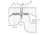
- FIG. 4 is an enlarged schematic cross-sectional view of the periphery of the convex portion 61 in the cylindrical battery 10.
- FIG. 4 and FIGS. 5 and 6 used below, for ease of understanding, the axial length of the gap created between the convex portion 61 of the upper current collector plate 50 and the concave portion 71 of the terminal cap 27 is shown. is exaggerated and the characteristics of the shape of the gap are exaggerated.
- the cylindrical battery 10 has a joint 75 that joins a part of the tip side of the protrusion 61 and a part of the bottom surface of the recess 71. Further, the cylindrical battery 10 has a first passage part 76 radially adjacent to the joint part 75 between the convex part 61 and the recess part 71, and a first passage part 76 on the joint part 75 side in the radial direction. It has a second passage section 77 that communicates with the opposite side and has a maximum length in the axial direction that is smaller than the maximum length in the axial direction of the first passage section 76 .
- the cylindrical battery 10 has a first passage part 76 and a second passage part 77 between the convex part 61 and the concave part 71.
- the first passage portion 76 is adjacent to the joint portion 75 in the radial direction.
- the second passage portion 77 is in communication with the first passage portion 76 on the opposite side of the joint portion 75 .
- the length of the portion of the second passage portion 77 that is the longest in the axial direction is smaller than the length of the portion of the first passage portion 76 that is the longest in the axial direction.
- the first passage portion 76 and the second passage portion 77 are present on both sides of the joint portion 75 in the radial direction.
- the joint portion 75, the first passage portion 76, and the second passage portion 77 extend in a circular shape when viewed from the radial direction of the cylindrical battery 10.
- the second passage portion 77 is a passage surrounded by a zigzag first line 78 that repeats unevenness and a zigzag second line 79 that repeats unevenness. Includes portion 81.
- the passage portion 81 becomes a zigzag passage portion that progresses in a zigzag manner.
- each of the terminal cap 27 and the upper current collector plate 50 has an uneven surface in which unevenness is repeated in the radial direction. Then, the uneven surface of the terminal cap 27 is arranged so that the uneven surface of the terminal cap 27 fits into the uneven surface of the upper current collector plate 50, and a passage portion 81 that progresses in a zigzag manner is formed between the two uneven surfaces. It faces the uneven surface of the upper current collector plate 50 in the axial direction.
- the uneven surfaces of the terminal cap 27 and the upper current collector plate 50 can be formed, for example, by pressing, polishing, or the like.
- a passage portion 81 that advances in a zigzag manner is formed throughout the entire radial direction of the second passage portion 77, and the second passage portion 77 coincides with the passage portion 81 that advances in a zigzag manner.
- the passage portion that progresses in a zigzag manner may be provided only in a portion of the second passage portion in the radial direction.
- the joint portion 75, the first passage portion 76, and the second passage portion 77 extend in a circular shape when viewed from the radial direction of the cylindrical battery 10
- the joint portion 75 does not necessarily have a circular shape. does not need to be formed.
- a plurality of joint portions may be formed in an arc shape. Note that in the case of a configuration including a plurality of joints, a first passage part and a second passage part are provided corresponding to each of the plurality of joints.
- the cylindrical battery 10 includes a bottomed cylindrical outer can 16 housing the electrode body 14, a terminal cap 27, a plurality of positive electrode leads 20 extending from the electrode body 14, and An upper current collector plate 50 to which a plurality of positive electrode leads 20 are bonded is provided.
- the upper current collector plate 50 has a convex portion 61 that protrudes toward the terminal cap 27 in the axial direction
- the terminal cap 27 has a concave portion 71 that accommodates at least the tip side of the convex portion 61. Further, a portion of the tip side of the convex portion 61 and a portion of the bottom surface of the recessed portion 71 are joined at a joint portion 75 .
- a first passage portion 76 adjacent to the joint portion 75 in the radial direction communicates with a side of the first passage portion 76 opposite to the joint portion side in the radial direction.
- a second passage section 77 having a maximum axial length that is smaller than the maximum axial length of passage section 76 .
- the second passage part 77 having a maximum length in the axial direction that is smaller than the maximum length in the axial direction of the first passage part 76 exists on the opposite side of the first passage part 76 from the joint part 75 side in the radial direction. Therefore, heat can be efficiently absorbed by the axially opposing surfaces on both axial sides of the second passage portion 77 having a narrow axial length.
- the thickness of the terminal cap 27 and the upper current collector plate 50 that overlap in the axial direction with the second passage portion 77 can be increased, the heat capacity of these parts can be increased. The amount of heat that can be absorbed can be increased. Therefore, for this reason as well, the flame extinguishing phenomenon can be effectively generated, so even if a flame occurs during laser welding, the flame can be extinguished in a short period of time, making the cylindrical battery 10 of high quality. can.
- first passage portion 76 and the second passage portion 77 are present on both sides of the joint portion 75 in the radial direction. Therefore, the radial existence range of the second passage portion 77 can be increased, and the extinguishing phenomenon can be caused more effectively.
- the second passage portion 77 includes a passage portion 81 that is surrounded by a zigzag first line 78 that repeats unevenness and a zigzag second line 79 that repeats unevenness and progresses in a zigzag manner. Therefore, the path length of the passage portion 81 that progresses in a zigzag manner can be increased, and the surface area of the passage portion 81 can be increased. Therefore, heat can be absorbed more effectively in the passage portion 81 that progresses in a zigzag pattern, so that the extinguishing effect can be more effectively generated.
- the axial length of the convex portion of the passage portion 81 that progresses in a zigzag manner is longer than the axial length of the convex portion of the convex portion of the unevenness caused by the grinding marks of the mold or the rolling roller.
- the axial length of the convex portion of the passage portion 81 is 0.05 mm to 1.5 mm, and more preferably, the axial length of the convex portion of the passage portion 81 is 0.1 mm to 1.0 mm.
- ⁇ Cylindrical battery of comparative example> In comparison with the cylindrical battery 10 of the above embodiment in which the terminal cap 27 and the upper current collector plate 50 are joined by the above-described laser welding, the cylindrical battery 10 has only the first passage part 76 and no second passage part 77. A battery was created. More specifically, in comparison with the cylindrical battery 10 of the above embodiment, a cylindrical battery was fabricated in which the extended portion of the first passage section 76 was present at the position where the second passage section 77 existed in the radial direction. The axial length of the first passage portion 76 was 2 mm.
- ⁇ Cylindrical battery of Example 1> The cylindrical battery 10 of the above embodiment was created.
- the terminal cap 27 and the upper current collector plate 50 were joined by the above-mentioned laser welding.
- the axial length of the second passage portion 77 that progresses in a zigzag manner is 0.1 mm.
- ⁇ Cylindrical battery of Example 2> The cylindrical battery 10 of the above embodiment was created.
- the terminal cap 27 and the upper current collector plate 50 were joined by the above-mentioned laser welding.
- the axial length of the second passage portion 77 that progresses in a zigzag manner was set to 0.5 mm.
- ⁇ Cylindrical battery of Example 3> The cylindrical battery 10 of the above embodiment was created.
- the terminal cap 27 and the upper current collector plate 50 were joined by the above-mentioned laser welding.
- the axial length of the second passage portion 77 that progresses in a zigzag manner was set to 1.0 mm.
- ⁇ Cylindrical battery of Example 4> The cylindrical battery 10 of the above embodiment was created.
- the terminal cap 27 and the upper current collector plate 50 were joined by the above-mentioned laser welding.
- the axial length of the second passage portion 77 that progresses in a zigzag manner was set to 1.5 mm.
- the maximum length in the axial direction of the second passage portion is 1 (mm) or less, since this can effectively cause an extinguishing phenomenon.
- the radial dimension of the area where the second passage portion exists is 0.2 (mm) or more because the contact area of the portion that can effectively absorb heat can be increased and the flame-extinguishing effect can be enhanced.
- the radial dimension of the area in which the second passage portion exists is 1 (mm) or less because it is easy to produce a compact cylindrical battery with a small radial dimension.
- the second passage portion 77 includes the passage portion 81 that progresses in a zigzag manner.
- the second passage section does not need to include a passage section that progresses in a zigzag manner.
- FIG. 5 that is, an enlarged schematic cross-sectional view of the modified cylindrical battery 110 corresponding to FIG. It may have.
- the inner surface of the second passage portion 177 can be reduced by narrowing the axial length of the second passage portion 177. It can absorb heat effectively and has a high anti-inflammatory effect. Furthermore, since the thickness of the portion of the terminal cap 127 that overlaps the second passage portion 177 in the axial direction and the thickness of the portion of the upper current collector plate 150 that overlaps the second passage portion 177 in the axial direction can be increased, the overlapping portion The heat capacity of can also be increased. Therefore, also for this reason, the anti-inflammatory effect can be enhanced.
- a portion of the terminal cap 127 that axially overlaps the second passage portion 177 has a protrusion 127a that protrudes downward in the axial direction.
- a portion of the upper current collector plate 150 that overlaps the second passage portion 177 in the axial direction has a protruding portion 150a that protrudes upward in the axial direction.
- a protrusion is formed only on one of the part of the terminal cap that overlaps the second passage part in the axial direction, and the part of the upper current collector plate that overlaps in the axial direction with the second passage part. It may be provided.
- FIG. 6 that is, an enlarged schematic cross-sectional view corresponding to FIG.
- the protrusion 227a that protrudes to the side is provided, the protrusion that protrudes upward in the axial direction may not be provided in the portion of the upper current collector plate 250 that overlaps the second passage portion 277 in the axial direction. Even in this case, good anti-inflammatory performance can be achieved.
- first passage portion 76 and the second passage portion 77 are present on both sides in the radial direction of the joint portion 75 provided by laser welding.
- first passage portion and the second passage portion may be present only on one side in the radial direction of the joint provided by laser welding.
- the cylindrical battery 10 includes only one annular insulating plate 18 above the electrode body 14.
- the cylindrical battery may include another insulating plate between the annular insulating plate and the electrode body, or may include two insulating plates doubly arranged above the electrode body.
- the electrical resistance of the cylindrical battery 10 is reduced by bonding the negative electrode current collector exposed portion 41 to the lower current collector plate 52 and bonding the lower current collector plate 52 to the bottom plate portion 68 of the outer can 16.
- the configuration in which the negative electrode current collector exposed portion 41 is joined to the lower current collector plate 52 may not be used.
- the negative electrode lead extending from the radially inner part of the negative electrode current collector exposed part is joined to the can bottom, and the outer peripheral surface of the electrode body is made of a negative electrode current collector without a negative electrode mixture layer.
- the negative electrode current collector constituting the outer peripheral surface of the electrode body may be brought into contact with the cylindrical inner peripheral surface of the outer can.
- the electrical resistance of the cylindrical battery can be reduced.
- the polarities may be reversed so that the terminal cap constitutes the negative electrode and the outer can constitutes the positive electrode.
Landscapes
- Chemical & Material Sciences (AREA)
- Chemical Kinetics & Catalysis (AREA)
- Electrochemistry (AREA)
- General Chemical & Material Sciences (AREA)
- Engineering & Computer Science (AREA)
- Manufacturing & Machinery (AREA)
- Materials Engineering (AREA)
- Sealing Battery Cases Or Jackets (AREA)
- Connection Of Batteries Or Terminals (AREA)
Priority Applications (4)
| Application Number | Priority Date | Filing Date | Title |
|---|---|---|---|
| CN202380046092.4A CN119343832A (zh) | 2022-06-30 | 2023-05-24 | 圆筒形电池 |
| US18/877,901 US20250379338A1 (en) | 2022-06-30 | 2023-05-24 | Cylindrical battery |
| EP23830903.3A EP4550564A4 (en) | 2022-06-30 | 2023-05-24 | CYLINDRICAL BATTERY |
| JP2024530377A JPWO2024004451A1 (https=) | 2022-06-30 | 2023-05-24 |
Applications Claiming Priority (2)
| Application Number | Priority Date | Filing Date | Title |
|---|---|---|---|
| JP2022-106661 | 2022-06-30 | ||
| JP2022106661 | 2022-06-30 |
Publications (1)
| Publication Number | Publication Date |
|---|---|
| WO2024004451A1 true WO2024004451A1 (ja) | 2024-01-04 |
Family
ID=89382652
Family Applications (1)
| Application Number | Title | Priority Date | Filing Date |
|---|---|---|---|
| PCT/JP2023/019299 Ceased WO2024004451A1 (ja) | 2022-06-30 | 2023-05-24 | 円筒形電池 |
Country Status (5)
| Country | Link |
|---|---|
| US (1) | US20250379338A1 (https=) |
| EP (1) | EP4550564A4 (https=) |
| JP (1) | JPWO2024004451A1 (https=) |
| CN (1) | CN119343832A (https=) |
| WO (1) | WO2024004451A1 (https=) |
Citations (4)
| Publication number | Priority date | Publication date | Assignee | Title |
|---|---|---|---|---|
| JP2005100927A (ja) * | 2003-08-28 | 2005-04-14 | Matsushita Electric Ind Co Ltd | 電池およびその製造方法 |
| JP2005150073A (ja) * | 2003-08-28 | 2005-06-09 | Matsushita Electric Ind Co Ltd | 電池およびその製造方法 |
| JP2007066599A (ja) * | 2005-08-30 | 2007-03-15 | Matsushita Electric Ind Co Ltd | 蓄電池および電池パック |
| WO2016098291A1 (ja) | 2014-12-16 | 2016-06-23 | 三洋電機株式会社 | 円筒形電池 |
Family Cites Families (2)
| Publication number | Priority date | Publication date | Assignee | Title |
|---|---|---|---|---|
| JP7559206B2 (ja) * | 2020-11-11 | 2024-10-01 | ジアンス・コンテンポラリー・アンプレックス・テクノロジー・リミテッド | 電池セル、電池、電力消費機器及び電池製造方法 |
| DE202024102979U1 (de) * | 2023-05-08 | 2024-07-25 | Lg Energy Solution, Ltd. | (Rollen-)Nahtschweißstruktur einer Batteriedose, einer Stromabnehmerplatte und einer Kappe und Batteriezelle mit derselben |
-
2023
- 2023-05-24 JP JP2024530377A patent/JPWO2024004451A1/ja active Pending
- 2023-05-24 EP EP23830903.3A patent/EP4550564A4/en active Pending
- 2023-05-24 CN CN202380046092.4A patent/CN119343832A/zh active Pending
- 2023-05-24 WO PCT/JP2023/019299 patent/WO2024004451A1/ja not_active Ceased
- 2023-05-24 US US18/877,901 patent/US20250379338A1/en active Pending
Patent Citations (4)
| Publication number | Priority date | Publication date | Assignee | Title |
|---|---|---|---|---|
| JP2005100927A (ja) * | 2003-08-28 | 2005-04-14 | Matsushita Electric Ind Co Ltd | 電池およびその製造方法 |
| JP2005150073A (ja) * | 2003-08-28 | 2005-06-09 | Matsushita Electric Ind Co Ltd | 電池およびその製造方法 |
| JP2007066599A (ja) * | 2005-08-30 | 2007-03-15 | Matsushita Electric Ind Co Ltd | 蓄電池および電池パック |
| WO2016098291A1 (ja) | 2014-12-16 | 2016-06-23 | 三洋電機株式会社 | 円筒形電池 |
Non-Patent Citations (1)
| Title |
|---|
| See also references of EP4550564A4 |
Also Published As
| Publication number | Publication date |
|---|---|
| CN119343832A (zh) | 2025-01-21 |
| EP4550564A1 (en) | 2025-05-07 |
| EP4550564A4 (en) | 2025-12-31 |
| US20250379338A1 (en) | 2025-12-11 |
| JPWO2024004451A1 (https=) | 2024-01-04 |
Similar Documents
| Publication | Publication Date | Title |
|---|---|---|
| US20110217576A1 (en) | Wound electrode assembly and battery | |
| US20250158243A1 (en) | Battery and current collector | |
| JP7808586B2 (ja) | 円筒形電池、及びその製造方法 | |
| WO2024071239A1 (ja) | 蓄電装置 | |
| CN111902968A (zh) | 电池以及其制造方法 | |
| JP7808606B2 (ja) | 円筒形電池及び円筒形電池の製造方法 | |
| US20240291119A1 (en) | Cylindrical battery | |
| JP7738641B2 (ja) | 円筒形電池 | |
| WO2025142806A1 (ja) | 円筒形二次電池 | |
| WO2024004451A1 (ja) | 円筒形電池 | |
| CN111919312A (zh) | 圆筒形电池以及其制造方法 | |
| JP7674111B2 (ja) | 電池、及び電池の製造方法 | |
| WO2025069835A1 (ja) | 円筒形電池 | |
| WO2026070618A1 (ja) | 円筒形電池 | |
| WO2026028553A1 (ja) | 円筒形電池 | |
| WO2026070472A1 (ja) | 蓄電装置 | |
| WO2025069750A1 (ja) | 円筒形電池 | |
| WO2025205532A1 (ja) | 円筒形電池の製造方法、及び円筒形電池 | |
| WO2025182621A1 (ja) | 円筒形二次電池 | |
| WO2025248987A1 (ja) | 蓄電装置 | |
| WO2025249412A1 (ja) | 蓄電装置 | |
| WO2025182714A1 (ja) | 非水電解質二次電池 | |
| WO2025164364A1 (ja) | 円筒形二次電池 | |
| WO2025182622A1 (ja) | 円筒形二次電池 | |
| WO2025142758A1 (ja) | 円筒形二次電池 |
Legal Events
| Date | Code | Title | Description |
|---|---|---|---|
| 121 | Ep: the epo has been informed by wipo that ep was designated in this application |
Ref document number: 23830903 Country of ref document: EP Kind code of ref document: A1 |
|
| WWE | Wipo information: entry into national phase |
Ref document number: 2024530377 Country of ref document: JP |
|
| WWE | Wipo information: entry into national phase |
Ref document number: 202380046092.4 Country of ref document: CN |
|
| WWE | Wipo information: entry into national phase |
Ref document number: 202417101075 Country of ref document: IN |
|
| WWE | Wipo information: entry into national phase |
Ref document number: 18877901 Country of ref document: US |
|
| WWP | Wipo information: published in national office |
Ref document number: 202380046092.4 Country of ref document: CN |
|
| WWE | Wipo information: entry into national phase |
Ref document number: 2023830903 Country of ref document: EP |
|
| NENP | Non-entry into the national phase |
Ref country code: DE |
|
| ENP | Entry into the national phase |
Ref document number: 2023830903 Country of ref document: EP Effective date: 20250130 |
|
| WWP | Wipo information: published in national office |
Ref document number: 2023830903 Country of ref document: EP |
|
| WWP | Wipo information: published in national office |
Ref document number: 18877901 Country of ref document: US |