WO2024004287A1 - 画像表示装置、及び光学系 - Google Patents
画像表示装置、及び光学系 Download PDFInfo
- Publication number
- WO2024004287A1 WO2024004287A1 PCT/JP2023/010413 JP2023010413W WO2024004287A1 WO 2024004287 A1 WO2024004287 A1 WO 2024004287A1 JP 2023010413 W JP2023010413 W JP 2023010413W WO 2024004287 A1 WO2024004287 A1 WO 2024004287A1
- Authority
- WO
- WIPO (PCT)
- Prior art keywords
- light
- image
- display device
- polarization state
- light guide
- Prior art date
- Legal status (The legal status is an assumption and is not a legal conclusion. Google has not performed a legal analysis and makes no representation as to the accuracy of the status listed.)
- Ceased
Links
Images


Classifications
-
- G—PHYSICS
- G02—OPTICS
- G02B—OPTICAL ELEMENTS, SYSTEMS OR APPARATUS
- G02B27/00—Optical systems or apparatus not provided for by any of the groups G02B1/00 - G02B26/00, G02B30/00
- G02B27/01—Head-up displays
-
- B—PERFORMING OPERATIONS; TRANSPORTING
- B60—VEHICLES IN GENERAL
- B60K—ARRANGEMENT OR MOUNTING OF PROPULSION UNITS OR OF TRANSMISSIONS IN VEHICLES; ARRANGEMENT OR MOUNTING OF PLURAL DIVERSE PRIME-MOVERS IN VEHICLES; AUXILIARY DRIVES FOR VEHICLES; INSTRUMENTATION OR DASHBOARDS FOR VEHICLES; ARRANGEMENTS IN CONNECTION WITH COOLING, AIR INTAKE, GAS EXHAUST OR FUEL SUPPLY OF PROPULSION UNITS IN VEHICLES
- B60K35/00—Instruments specially adapted for vehicles; Arrangement of instruments in or on vehicles
- B60K35/20—Output arrangements, i.e. from vehicle to user, associated with vehicle functions or specially adapted therefor
- B60K35/21—Output arrangements, i.e. from vehicle to user, associated with vehicle functions or specially adapted therefor using visual output, e.g. blinking lights or matrix displays
- B60K35/23—Head-up displays [HUD]
- B60K35/234—Head-up displays [HUD] controlling the brightness, colour or contrast of virtual images depending on the driving conditions or on the condition of the vehicle or the driver
-
- B—PERFORMING OPERATIONS; TRANSPORTING
- B60—VEHICLES IN GENERAL
- B60K—ARRANGEMENT OR MOUNTING OF PROPULSION UNITS OR OF TRANSMISSIONS IN VEHICLES; ARRANGEMENT OR MOUNTING OF PLURAL DIVERSE PRIME-MOVERS IN VEHICLES; AUXILIARY DRIVES FOR VEHICLES; INSTRUMENTATION OR DASHBOARDS FOR VEHICLES; ARRANGEMENTS IN CONNECTION WITH COOLING, AIR INTAKE, GAS EXHAUST OR FUEL SUPPLY OF PROPULSION UNITS IN VEHICLES
- B60K35/00—Instruments specially adapted for vehicles; Arrangement of instruments in or on vehicles
- B60K35/40—Instruments specially adapted for improving the visibility thereof to the user, e.g. fogging prevention or anti-reflection arrangements
- B60K35/415—Glare prevention
-
- B—PERFORMING OPERATIONS; TRANSPORTING
- B60—VEHICLES IN GENERAL
- B60K—ARRANGEMENT OR MOUNTING OF PROPULSION UNITS OR OF TRANSMISSIONS IN VEHICLES; ARRANGEMENT OR MOUNTING OF PLURAL DIVERSE PRIME-MOVERS IN VEHICLES; AUXILIARY DRIVES FOR VEHICLES; INSTRUMENTATION OR DASHBOARDS FOR VEHICLES; ARRANGEMENTS IN CONNECTION WITH COOLING, AIR INTAKE, GAS EXHAUST OR FUEL SUPPLY OF PROPULSION UNITS IN VEHICLES
- B60K35/00—Instruments specially adapted for vehicles; Arrangement of instruments in or on vehicles
- B60K35/80—Arrangements for controlling instruments
- B60K35/81—Arrangements for controlling instruments for controlling displays
-
- G—PHYSICS
- G02—OPTICS
- G02B—OPTICAL ELEMENTS, SYSTEMS OR APPARATUS
- G02B27/00—Optical systems or apparatus not provided for by any of the groups G02B1/00 - G02B26/00, G02B30/00
- G02B27/0081—Optical systems or apparatus not provided for by any of the groups G02B1/00 - G02B26/00, G02B30/00 with means for altering, e.g. enlarging, the entrance or exit pupil
-
- G—PHYSICS
- G02—OPTICS
- G02B—OPTICAL ELEMENTS, SYSTEMS OR APPARATUS
- G02B27/00—Optical systems or apparatus not provided for by any of the groups G02B1/00 - G02B26/00, G02B30/00
- G02B27/01—Head-up displays
- G02B27/0101—Head-up displays characterised by optical features
-
- G—PHYSICS
- G02—OPTICS
- G02B—OPTICAL ELEMENTS, SYSTEMS OR APPARATUS
- G02B27/00—Optical systems or apparatus not provided for by any of the groups G02B1/00 - G02B26/00, G02B30/00
- G02B27/01—Head-up displays
- G02B27/017—Head mounted
- G02B27/0172—Head mounted characterised by optical features
-
- G—PHYSICS
- G02—OPTICS
- G02B—OPTICAL ELEMENTS, SYSTEMS OR APPARATUS
- G02B27/00—Optical systems or apparatus not provided for by any of the groups G02B1/00 - G02B26/00, G02B30/00
- G02B27/28—Optical systems or apparatus not provided for by any of the groups G02B1/00 - G02B26/00, G02B30/00 for polarising
- G02B27/286—Optical systems or apparatus not provided for by any of the groups G02B1/00 - G02B26/00, G02B30/00 for polarising for controlling or changing the state of polarisation, e.g. transforming one polarisation state into another
-
- B—PERFORMING OPERATIONS; TRANSPORTING
- B60—VEHICLES IN GENERAL
- B60K—ARRANGEMENT OR MOUNTING OF PROPULSION UNITS OR OF TRANSMISSIONS IN VEHICLES; ARRANGEMENT OR MOUNTING OF PLURAL DIVERSE PRIME-MOVERS IN VEHICLES; AUXILIARY DRIVES FOR VEHICLES; INSTRUMENTATION OR DASHBOARDS FOR VEHICLES; ARRANGEMENTS IN CONNECTION WITH COOLING, AIR INTAKE, GAS EXHAUST OR FUEL SUPPLY OF PROPULSION UNITS IN VEHICLES
- B60K2360/00—Indexing scheme associated with groups B60K35/00 or B60K37/00 relating to details of instruments or dashboards
- B60K2360/20—Optical features of instruments
- B60K2360/33—Illumination features
- B60K2360/336—Light guides
-
- B—PERFORMING OPERATIONS; TRANSPORTING
- B60—VEHICLES IN GENERAL
- B60K—ARRANGEMENT OR MOUNTING OF PROPULSION UNITS OR OF TRANSMISSIONS IN VEHICLES; ARRANGEMENT OR MOUNTING OF PLURAL DIVERSE PRIME-MOVERS IN VEHICLES; AUXILIARY DRIVES FOR VEHICLES; INSTRUMENTATION OR DASHBOARDS FOR VEHICLES; ARRANGEMENTS IN CONNECTION WITH COOLING, AIR INTAKE, GAS EXHAUST OR FUEL SUPPLY OF PROPULSION UNITS IN VEHICLES
- B60K2360/00—Indexing scheme associated with groups B60K35/00 or B60K37/00 relating to details of instruments or dashboards
- B60K2360/20—Optical features of instruments
- B60K2360/33—Illumination features
- B60K2360/349—Adjustment of brightness
-
- B—PERFORMING OPERATIONS; TRANSPORTING
- B60—VEHICLES IN GENERAL
- B60K—ARRANGEMENT OR MOUNTING OF PROPULSION UNITS OR OF TRANSMISSIONS IN VEHICLES; ARRANGEMENT OR MOUNTING OF PLURAL DIVERSE PRIME-MOVERS IN VEHICLES; AUXILIARY DRIVES FOR VEHICLES; INSTRUMENTATION OR DASHBOARDS FOR VEHICLES; ARRANGEMENTS IN CONNECTION WITH COOLING, AIR INTAKE, GAS EXHAUST OR FUEL SUPPLY OF PROPULSION UNITS IN VEHICLES
- B60K2360/00—Indexing scheme associated with groups B60K35/00 or B60K37/00 relating to details of instruments or dashboards
- B60K2360/92—Manufacturing of instruments
-
- G—PHYSICS
- G02—OPTICS
- G02B—OPTICAL ELEMENTS, SYSTEMS OR APPARATUS
- G02B27/00—Optical systems or apparatus not provided for by any of the groups G02B1/00 - G02B26/00, G02B30/00
- G02B27/01—Head-up displays
- G02B27/0101—Head-up displays characterised by optical features
- G02B2027/0118—Head-up displays characterised by optical features comprising devices for improving the contrast of the display / brillance control visibility
-
- G—PHYSICS
- G02—OPTICS
- G02B—OPTICAL ELEMENTS, SYSTEMS OR APPARATUS
- G02B27/00—Optical systems or apparatus not provided for by any of the groups G02B1/00 - G02B26/00, G02B30/00
- G02B27/01—Head-up displays
- G02B27/0101—Head-up displays characterised by optical features
- G02B2027/0127—Head-up displays characterised by optical features comprising devices increasing the depth of field
Definitions
- the present disclosure relates to an image display device that allows an observer to view an optical image such as a virtual image, and an optical system used in the image display device.
- Patent Document 1 discloses an optical display system including a plurality of diffractive optical elements (DOE) for pupil dilation in a virtual reality or mixed reality head mounted display (HMD) device or the like.
- DOE diffractive optical elements
- HMD mixed reality head mounted display
- a main beam from an imager propagates from a first DOE to a second DOE, such as as a TM polarized beam or a TE polarized beam.
- the second DOE includes grating features configured to rotate the state of polarization of the optical perturbation.
- light interference is reduced by rotating the polarization of the perturbation beam to be orthogonal to the polarization of the main beam used for image display.
- the present disclosure provides an image display device and an optical system that can suppress fluctuations in image quality in an image display device that makes a virtual image visible.
- An image display device in the present disclosure is an image display device that allows an optical image to be viewed, and includes a display unit that emits image light that is viewed as an optical image, and a light guide that guides the image light from the display unit to the outside. Equipped with.
- the light guide has a pair of principal surfaces facing each other. In the light guide, the image light from the display section is incident and propagated inside the light guide by reflection between a pair of main surfaces. At a plurality of positions where the light propagates, extension regions are provided that diffract the propagated image light and emit the image light as a plurality of image lights.
- the image light propagated to the expansion area becomes a first polarization state in which it is polarized along a direction parallel or perpendicular to a plane including the normal direction of the main surface in the expansion area and the propagation direction of the propagated image light.
- the image light incident on the incident region is set to a second polarization state different from the first polarization state.
- the optical system in the present disclosure includes a light guide that guides image light from a display section that emits image light that is visually recognized as an optical image to the outside, and a polarization setting that is arranged between the display section and the light guide. It is equipped with a section.
- the light guide has a pair of main surfaces facing each other. In the light guide, the image light from the display section is incident and propagated inside the light guide by reflection between a pair of main surfaces. At a plurality of positions where the light propagates, extension regions are provided that diffract the propagated image light and emit the image light as a plurality of image lights.
- the polarization setting unit includes a first polarization unit in which the image light propagated to the expansion area is polarized along a direction parallel or perpendicular to a plane including the normal direction of the main surface in the expansion area and the propagation direction of the propagated image light.
- the image light incident on the incident region is set to a second polarization state different from the first polarization state so that the image light has a polarization state of .
- the image display device and optical system of the present disclosure it is possible to suppress fluctuations in image quality in the image display device that makes a virtual image visible.
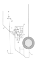
- a diagram for explaining an overview of a head-up display system according to Embodiment 1 of the present disclosure A diagram illustrating the configuration of a head-up display system according to Embodiment 1.
- Diagram for explaining pupil dilation operation in the image display device of Embodiment 1 A diagram illustrating a polarization state in the image display device of Embodiment 1.
- Embodiment 1 of the present disclosure will be described below with reference to the drawings. In this embodiment, an example of a system to which a pupil expansion type image display device and optical system are applied will be described.
- FIG. 1 is a diagram for explaining an overview of a head-up display (HUD) system 1 according to the present embodiment.
- the HUD system 1 includes, for example, as shown in FIG. 1, an image display device 2 and a windshield 5.
- the HUD system 1 is a system that allows an observer D such as a passenger to visually recognize a virtual image Iv as an example of an optical image, for example in a vehicle 3 or the like in which a windshield 5 is provided.
- the area where the observer D's eyes are positioned so that the virtual image Iv becomes visible to the observer D is referred to as a visibility area Ac.
- the image display device 2 of this embodiment includes a display unit 11 that generates image light L1 that is visually recognized as a virtual image Iv, and a pupil (for example, an exit pupil) of the image light L1 from the display unit 11.
- the light guide 13 is expanded to guide the expanded image light L2 to the windshield 5. According to such a pupil expansion type image display device 2, it is easy to ensure a large viewing area Ac in the HUD system 1.
- the pupil dilation technology When the pupil dilation technology is applied to a HUD, there may be a problem that, for example, the brightness of the virtual image Iv changes when the observer D moves his or her eyes within the viewing area Ac, resulting in noticeable brightness unevenness and fluctuations in image quality. Therefore, in this embodiment, in order to solve the problem of such brightness unevenness and suppress fluctuations in image quality, a configuration is adopted in which polarization in the pupil expansion type image display device 2 is controlled. The configuration of the image display device 2 in the HUD system 1 of this embodiment will be described below.
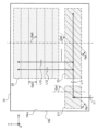
- FIG. 2 illustrates the configuration of the HUD system 1 according to this embodiment.
- the image display device 2 is arranged, for example, inside a dashboard (not shown) below the windshield 5 of the vehicle 3.
- the image display device 2 of this embodiment includes a display section 11, a light guide 13, a polarization setting section 14, and a control section 15, as shown in FIG. 2, for example.
- the optical system 20 composed of the light guide 13 and the polarization setting section 14 is an example of an optical system in the image display device 2 of this embodiment.
- the windshield 5 is an example of a light-transmitting member provided on a moving object such as the vehicle 3.
- the light-transmitting member of the HUD system 1 is not limited to the windshield 5, and may be any of various members having light-transmitting properties in the visible light region, such as a combiner.
- the display unit 11 is a display element that has a display surface that displays an image using, for example, a plurality of pixels, and that generates image light L1 that represents the image on the display surface.
- the display unit 11 includes a liquid crystal display, an organic light-emitting diode (organic light-emitting diode) display, an LCOS (liquid crystal on silicon), a DMD (digital mirror device), a micro LED, or a scanning MEMS mirror.
- the display unit 11 does not need to have a display surface inside.
- a display surface such as a screen may be provided outside the display unit 11.
- the display unit 11 may include various light sources such as a laser light source or an LED light source that emit light in a single color or multiple colors to generate the image light L1.
- the image light L1 is composed of a light beam having a divergence angle corresponding to the angle of view of the image, for example.
- the optical paths of light rays such as the central ray are illustrated as appropriate in the drawings.
- the light guide 13 is a light guide member that is formed of a material that is transparent in the visible light region and is configured to allow total internal reflection of incident light.
- the light guide 13 has a pair of principal surfaces 13a and 13b facing each other.
- the light guide 13 is not limited to a planar shape, but may have a curved shape. Below, a configuration example of the light guide 13 having a planar shape in which the first main surface 13a and the second main surface 13b are parallel will be described.
- the image display device 2 may include a plurality of light guides 13. For example, light guides 13 for different colors of RGB may be used.
- the light guide 13 is composed of, for example, a glass or resin plate whose main surfaces 13a and 13b are mirror-finished.
- the normal direction of the main surfaces 13a and 13b of the light guide 13 will be referred to as the Z direction
- the two directions parallel to the main surfaces 13a and 13b and orthogonal to each other will be referred to as the X and Y directions.
- the X direction corresponds to the horizontal direction of the virtual image Iv
- the Y direction corresponds to the vertical direction of the virtual image Iv.
- the light guide 13 is arranged in the vehicle 3, for example, with the first principal surface 13a on the -Z side facing downward and the second principal surface 13b on the +Z side facing upward.
- the light guide 13 is arranged at an angle in the vehicle 3 as shown in FIG. 2, for example, according to various arrangement restrictions.
- the arrangement constraints of the light guide 13 are, for example, to prevent reflected light when sunlight or the like from outside the vehicle 3 enters the light guide 13 through the windshield 5 from reaching the visibility area Ac. be.
- the light guide 13 allows the image light L1 incident from the display section 11 on the -Z side and the image light L2 emitted to the windshield 5 on the +Z side to be directed to each main surface 13a. , 13b, respectively, so as to be inclined in the Y direction.
- the light guide 13 is provided with a diffraction structure for realizing the pupil dilation operation. Details of the configuration of the light guide 13 will be described later.
- the polarization setting unit 14 is composed of various optical elements disposed between the display unit 11 and the light guide 13, for example, and sets the image light L1 entering the light guide 13 from the display unit 11 into a specific polarization state. Set.
- the polarization setting unit 14 includes one or more optical elements of a half-wave plate, a quarter-wave plate, and a polarizing plate.
- the polarization setting section 14 may be incorporated into various optical systems such as a collimator provided between the display section 11 and the light guide 13, or may be configured integrally with the display section 11 or the light guide 13. good.
- the image display device 2 does not need to include an optical element as the polarization setting section 14.
- the function of the polarization setting unit 14 is to rotate the image light L1 in the optical axis direction. This may be realized by alignment with the light guide 13.
- the control unit 15 controls the entire operation of the image display device 2, for example.
- the control unit 15 can be realized by a circuit made up of semiconductor elements or the like.
- the control unit 15 can be configured with, for example, a microcomputer, CPU, MPU, GPU, DSP, FPGA, or ASIC.
- the control unit 15 realizes predetermined functions by reading data and programs stored in an internal memory or the like and performing various arithmetic operations.
- the control unit 15 also includes a storage device 17 such as an internal memory.
- the control unit 15 may be an external component of the image display device 2.
- the storage device 17 is a storage medium that stores programs and data necessary to realize the functions of the control unit 15.
- the storage device 17 can be realized by, for example, a hard disk (HDD), SSD, RAM, DRAM, ferroelectric memory, flash memory, magnetic disk, or a combination thereof.
- the storage device 17 stores a plurality of image data representing the virtual image Iv.
- the storage device 17 stores image content data for displaying various information on the display unit 11, such as a road progress guide display, the distance to the vehicle in front, the remaining battery level of the car, and the current vehicle speed.
- the storage device 17 is not limited to the internal memory of the control unit 15, but may be an external configuration of the control unit 15.
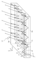
- FIG. 3 is a plan view showing an example of the configuration of the light guide 13 in the image display device 2. As shown in FIG.
- the light guide 13 includes a coupling region 21, a first expansion region 23, and a second expansion region 25, as shown in FIG. 3, for example.
- Each of the regions 21, 23, and 25 constitutes a diffraction structure element by providing a diffraction structure for realizing each diffraction power in the light guide 13.
- the first extension region 23 is arranged on the +X side of the coupling region 21, and the second extension region 25 is arranged on the +Y side of the first extension region 23.
- the diffraction structures of the regions 21, 23, and 25 in the light guide 13 can be configured with various periodic structures that can realize light diffraction, such as a volume hologram or a diffraction grating.
- a configuration example in which each diffraction structure of the light guide 13 is provided by a volume hologram between the first and second main surfaces 13a and 13b will be described.
- the volume hologram is composed of a periodic refractive index distribution within a dielectric film, such as interference fringes formed inside the light guide 13, for example.
- each region 21, 23, 25 may be a three-dimensional region in the light guide 13, respectively.
- the coupling region 21 is an example of an incident region that diffracts the incident image light L1 so as to optically couple with the image light L1 from the display section 11 in the light guide 13.
- the optical coupling is a state in which the light incident on the coupling region 21 satisfies the total internal reflection condition and propagates inside the light guide 13.
- the coupling region 21 has a diffraction power for converting the direction of the incident image light L1 into the image light L11 (hereinafter also referred to as "propagating light L11") that propagates in the X direction toward the first extension region 23. is set.
- the diffraction structure of the coupling region 21 has a diffraction pitch Gp1 and an inclination angle Ga1 for realizing the above-mentioned diffraction power.
- the diffraction pitch Gp1 indicates the period of the diffraction structure, such as the period of interference fringes in a hologram.
- the inclination angle Ga1 indicates, for example, the inclination of the direction in which the interference fringes extend with respect to a predetermined reference direction (for example, the Y direction). For example, in the example shown in FIG.
- the direction in which the image light L1 enters from the display unit 11 is inclined from the Z direction of the normal line to the coupling region 21 to the ⁇ Y side, so that the negative value (( In other words, an inclination angle Ga1 (clockwise) is set.
- the first expansion region 23 is a region in which diffraction is performed to expand the image light L11 (i.e., the propagation light L11) propagating by total reflection between the main surfaces 13a and 13b of the light guide 13 in the first propagation direction. .
- the expansion of the image light L11 is performed by dividing and duplicating the light beam of the image light L11 by diffraction a plurality of times, and emitting a plurality of light beams of the image light L12.
- the image light L12 of each light beam divided at this time is also referred to as "divided light L12" hereinafter.
- each divided light L12 after diffracted from the propagating light L11 having the X direction as the first propagation direction is transferred to the first expansion region 23 in the Y direction as the second propagation direction.
- the diffraction power for outputting to the second expansion region 25 is set toward.
- the diffraction structure of the first expansion region 23 has a diffraction pitch Gp2 and an inclination angle Ga2 to achieve relatively large diffraction power as described above.
- the diffraction pitch Gp2 of the first expansion region 23 is narrower than the diffraction pitch Gp1 of the coupling region 21, for example.
- the inclination angle Ga2 of the diffraction structure of the first expansion region 23 has a negative value, for example, like the inclination angle Ga1 of the diffraction structure of the coupling region 21, and is, for example, a larger angle than the inclination angle Ga1.
- the second expansion region 25 is a region where diffraction is performed to expand the propagating image light L12 in a second propagation direction intersecting the first propagation direction.
- the first and second propagation directions are not limited to the X and Y directions, but only need to intersect with each other, and do not need to be perpendicular to each other.
- the image light L12 is expanded in the second propagation direction in the second expansion region 25, the image light of each light beam that is divided and duplicated is hereinafter also referred to as "duplicated light" (not shown in FIG. 3).
- the duplicate light beams of the plurality of light beams constitute image light L2 as an expansion result (see FIG. 4).
- the duplicate light after being diffracted from the image light L12 that is totally reflected inside the light guide 13 while propagating in the Y direction does not satisfy the total reflection condition and is emitted to the outside.
- the diffraction power is set (see Figure 4). Since the diffraction power of the second extension region 25 is smaller than the diffraction power of the first extension region 23 described above, the diffraction pitch Gp3 of the second extension region 25 is, for example, smaller than the diffraction pitch Gp2 of the first extension region 23. wide. Further, the diffraction structure of the second expansion region 25 has, for example, an inclination angle Ga3 that is perpendicular to the second propagation direction (Y direction) and extends in the first propagation direction (X direction).
- the light guide 13 is not limited to the above configuration example, and various configurations can be adopted.
- the diffraction structure of each region 21, 23, 25 in the light guide 13 is not limited to a volume hologram, but may be composed of a diffraction grating or the like.
- the diffraction structures of each region 21, 23, 25 may be provided on the first or second main surface 13a, 14b of the light guide 13.
- each region 21, 23, 25 is not particularly limited to this, and may be inclined in various planes including the Z direction, for example.
- the control unit 15 of the image display device 2 determines the virtual image Iv to be displayed based on various information such as the driving environment acquired within the vehicle 3, for example.
- the control unit 15 reads the image data of the determined virtual image Iv from the storage device 17 and outputs it to the display unit 11.
- the display section 11 generates image light L1 representing an image under the control of the control section 15, and emits the generated image light L1.
- the image light L1 from the display section 11 enters the coupling region 21 of the light guide 13 in a state where the polarization setting section 14 sets a specific polarization state, for example.
- the incident image light L1 is two-dimensionally divided and duplicated by the pupil dilation operation in the first and second expansion regions 23 and 25 (details will be described later).
- the image light L2 expanded in this way is emitted from the light guide 13 to the windshield 5.
- the image light L2 incident on the windshield 5 is reflected and projected onto the viewing area Ac.
- the observer D can recognize the image light L2 projected from the HUD system 1 as a virtual image Iv by positioning his/her eyes in the viewing area Ac.
- the HUD system 1 displays the virtual image Iv superimposed on the real scene visible through the windshield 5.
- the image light L2 including a plurality of replication results is projected onto the viewing area Ac, so that even if the position of the eyes of the observer D shifts, as long as it is within the viewing area Ac, the viewer D can see the virtual image. Iv can be visually recognized.
- FIG. 4 is a perspective view of the light guide 13 of the image display device 2, illustrating optical paths such as the center rays of various image lights L1, L11 to L13, and L2.
- the image light L1 from the display section 11 is directed from the second principal surface 13b of the light guide 13 in the Z direction of the normal in the polarization state set by the polarization setting section 14, for example.
- the light enters the light guide 13 at an angle in the Y direction.
- the incident image light L1 is refracted, for example, at the light guide 13 and reaches the diffraction structure of the coupling region 21. Note that when the diffraction structure of the coupling region 21 is provided on the second main surface 13b, the image light L1 enters the diffraction structure of the coupling region 21 before being refracted at the light guide 13.
- the diffraction structure of the coupling region 21 diffracts the image light L1 so as to optically couple with the incident image light L1.
- the diffracted image light L11 of the coupling region 21 is direction-changed into propagation light L11 that propagates in the X direction toward the first extension region 23. Due to the diffraction in the coupling region 21, the propagating light L11 is completely reflected in the Fresnel reflection of the light guide 13 with respect to the normal (Z direction) of each principal surface 13a, 13b in the first extension region 23 of the light guide 13, for example.
- the incident angle ⁇ 1 is greater than or equal to the critical angle, which is the minimum angle at which reflection occurs.
- the propagating light L11 from the coupling region 21 propagates in the X direction every time it is reflected between the first and second main surfaces 13a and 13b of the light guide 13 in the first extension region 23. passes through a plurality of positions P1 lined up in the X direction in the diffraction structure.
- FIG. 4 illustrates four diffraction positions P1 in the first expansion region 23, the number of diffraction positions P1 is not particularly limited.
- the passing position from the -Z side to the +Z side is the diffraction position P1, but in addition to or instead of this, the passing position from the +Z side to the -Z side is the diffraction position P1. There may be.
- the diffraction structure of the first extension region 23 is such that a part of the propagating light L11 is split into split light L12 at each diffraction position P1, and the split light L12 propagates in the Y direction toward the second extension region 25. , sequentially diffract the propagating light L11.
- the image light L1 can be expanded in the X direction by the plurality of divided beams L12 lined up in the X direction, which are divided and duplicated from the propagating light L11 in the first expansion region 23.
- the divided light L12 is, for example, at a critical angle of the light guide 13 with respect to the normal (Z direction) of each main surface 13a, 13b of the light guide 13 in the second expansion region 25.
- the angle of incidence is greater than or equal to the angle of incidence.
- the plurality of divided beams L12 from the first expansion region 23 are repeatedly reflected within the light guide 13 during propagation in the Y direction, so that they each reach a plurality of positions P2 arranged in the Y direction in the second expansion region 25. pass.
- three diffraction positions P2 are illustrated for one divided light L12, but the number of diffraction positions P2 is not particularly limited.
- the diffraction structure of the second expansion region 25 is such that at each diffraction position P3, a part of each divided light L12 is further divided and emitted to the outside of the light guide 13 as duplicated light L13 indicating the result of divided duplication. , each of the divided beams L12 is sequentially diffracted. In this way, the image light L1 can be expanded in the Y direction by the plurality of duplicate lights L13 arranged in the Y direction, which are obtained for each divided light beam L12 in the second expansion region 25.
- the duplicated light L13 Due to the effect of pupil expansion in two directions in the first and second expansion regions 23 and 25, image light L2 expanded in the X and Y directions is obtained. Due to the diffraction in the second expansion region 25, the duplicated light L13 has an angle less than the critical angle of the light guide 13 with respect to the normal (Z direction) to the first main surface 13a of the light guide 13 in the second expansion region 25, for example. has an angle of incidence of
- the luminous flux of the image light L1 from the display section 11 is diffracted in the first and second expansion regions 23 and 25 of the light guide 13. This can be expanded to a luminous flux of image light L2 including a plurality of duplicate lights L13 copied by.
- FIGS. 5A to 5C are graphs illustrating the polarization state in the image display device 2 of this embodiment.
- the horizontal axis of each graph corresponds to P-polarized light
- the vertical axis corresponds to S-polarized light.
- P-polarized light is a polarized state of linearly polarized light in which the direction of the electric field of light is parallel to the incident plane
- S-polarized light is a polarized state of linearly polarized light in which the direction of the electric field is perpendicular to the incident plane.
- the plane of incidence is a plane defined parallel to the light ray direction before and after the light is incident.
- FIG. 5(A) illustrates the polarization state of the image light L1 that enters the coupling region 21 in the image display device 2 of this embodiment.
- the polarization state of the image light L1 when it enters the coupling region 21 is defined, for example, using a plane W (FIG. 4) including the center ray of the image lights L1 and L11 before and after diffraction in the coupling region 21 as the plane of incidence.
- FIG. 5(B) illustrates the polarization state of the propagating light L11 in the first extension region 23 from the image light L1 of FIG. 5(A).
- the polarization state of the propagating light L11 is defined, for example, using the XZ plane as an incident plane for propagation to the first extension region 23 (see FIG. 4). Since propagation to the first expansion region 23 is based on reflection at each of the main surfaces 13a and 13b orthogonal to the incident surface in the first expansion region 23, the polarization state of the propagated light L11 is It can be specified using
- the polarization state of the propagating light L11 in the first extension region 23 is set to P polarization as shown in FIG. 5(B). has been done.
- the polarization state of the propagating light L11 deviates from the polarization state of the original image light L1 due to diffraction such as direction conversion from the image light L1 to the propagating light L11 in the coupling region 21.
- the image display device 2 of this embodiment as shown in FIGS. 5A and 5B, for example, by setting the polarization state of the image light L1 to be shifted from P-polarized light, etc., The polarization state of L11 is controlled. Thereby, in the image display device 2 of this embodiment, it is possible to suppress fluctuations in the diffraction efficiency from the propagating light L11 to the divided light L12 in the first extension region 23, and to solve the problem of brightness unevenness (details will be described later).
- the polarization state of the image light L1 is set to linearly polarized light that is shifted from P-polarized light by a specific polarization angle ⁇ .
- the polarization angle is expressed, for example, as a rotation angle of the polarization direction in a plane perpendicular to the optical axis direction of the central ray of the image light L1.
- the specific polarization angle ⁇ is set in consideration of the amount of change in the polarization angle before and after diffraction in the coupling region 21 in order to realize a desired polarization state of the propagating light L11 as shown in FIG. 5(B).
- the setting of the polarization angle ⁇ in the coupling region 21 may be performed, for example, by measuring the polarization state of the propagating light L11 while changing the polarization state of the image light L1, or may be performed based on theoretical calculations.
- the amount of change described above may include the incident angle, wavelength, polarization state at which the image light L1 enters the coupling region 21, the arrangement of the coupling region 21 and the first extension region 23, the refractive index of the coupling region 21, the diffraction pitch Gp1, and It can be calculated from the inclination angle Ga1 and the like.
- FIG. 5(C) illustrates the polarization state of the split light L12 in the second extension region 25 from the propagating light L11 in FIG. 5(B).
- the polarization state of the divided light L12 is defined using, for example, the YZ plane as the incident plane for propagation to the second extension region 25.
- the polarization state of the replication light L13 is also defined using the YZ plane as the incident plane for diffraction in the second extension region 25.
- the polarization state of the split light L12 changes from the linearly polarized light of FIG. 5(B) to elliptically polarized light.
- the polarization state of the split light L12 in the second extension region 25 is changed by the diffraction of the split copy from the propagation light L11 into the split light L12 in the first extension region 23, the propagation in the second extension region 25, etc. can vary from the polarization state of In the image display device 2 of this embodiment, the polarization state in the second expansion region 25 may vary. Even with such fluctuations, the problem of brightness unevenness in the image display device 2 can be solved by controlling the polarization state in the first expansion region 23.
- the problem of brightness unevenness is that in conventional pupil expansion type image display devices, the polarization of the propagating light L11 is unstable. It has become clear that this is caused by the fact that the diffraction efficiency for obtaining the light L12 fluctuates.
- the inventors of the present application have conducted intensive research and have devised an image display device 2 that can improve brightness unevenness by stabilizing the polarization state of the propagating light L11.
- FIGS. 6A to 6C are diagrams for explaining the stability of the polarization state of the propagating light L11 in the light guide 13.
- FIGS. 6A to 6C illustrate the polarization states of the propagating light L11 at various diffraction positions P1 (see FIG. 4) with different numbers of reflections in the first extension region 23.
- FIG. 6(A) illustrates a case where the polarization state of the propagating light L11 is unstable.
- the polarization state of the original image light L1 is set to P polarization
- the polarization state of the propagating light L11 changes at the initial stage of propagation from the coupling region 21 to the first extension region 23 (for example, when the number of reflections is 0).
- the polarization direction is rotated by the polarization angle ⁇ from the P-polarized light to become linearly polarized light.
- FIG. 6(A) illustrates a case where the polarization angle ⁇ of the initial propagating light L11 is relatively large, such as approximately 45°.
- the polarization state of the k2 propagating light L11 becomes linearly polarized light with a polarization angle ⁇ of approximately ⁇ 45° every time Fresnel reflection is repeated during propagation through the first expansion region 23. It fluctuates between elliptically polarized light, etc. If the diffraction power is relatively large, such an unstable polarization state may affect the diffraction efficiency from the propagating light L11 to the split light L12.
- FIG. 7 is a graph illustrating the relationship between the polarization state of the propagating light L11 and the diffraction efficiency at a certain diffraction position P1 of the first extension region 23.
- the horizontal axis in FIG. 7 is the polarization angle [°] of the propagating light L11, and the vertical axis is the diffraction efficiency [%].
- the rate of variation between the maximum value and the minimum value of the diffraction efficiency hardly changes. Therefore, in the case of FIG. 6A, the diffraction efficiency at the plurality of diffraction positions P1 in the first expansion region 23 varies over such a wide range. Therefore, there may be a problem that the amount of light varies among the plurality of divided beams L12 corresponding to each diffraction position P1, resulting in uneven brightness that deteriorates the image quality of the virtual image Iv.
- the image display device 2 of the present embodiment adjusts the polarization of the image light L1 so that, for example, the initially propagated light L11 propagating to the first expansion region 23 has a polarization state of P polarization or S polarization.
- the state is set to be shifted from P-polarized light or S-polarized light.
- FIG. 6(B) shows an example of the polarization state of the propagating light L11 in the image display device 2 of this embodiment.
- FIG. 6C shows another example of the polarization state of the propagating light L11 in the image display device 2 of this embodiment.
- FIG. 6(B) illustrates a case where the initial polarization state of the propagating light L11 in the first expansion region 23 is P-polarized light.
- the polarization state of the k2 propagating light L11 is as shown in FIG. As shown in , it remains stable as P-polarized light.
- variations in diffraction efficiency at various diffraction positions P1 (FIG. 4) in the first extension region 23 can be suppressed.
- a diffraction efficiency of about 80% can be stably obtained over the plurality of divided beams L12 at various diffraction positions P1.
- FIG. 6C illustrates a case where the initial polarization state of the propagating light L11 in the first expansion region 23 is S polarization.
- the polarization state of the propagating light L11 can be stabilized as S-polarized light against reflection during propagation in the first extension region 23, and variations in diffraction efficiency can be suppressed. Can be done. In this way, it is possible to reduce unevenness in brightness due to variations in the amount of light among the plurality of divided lights L12, and to suppress fluctuations in the image quality of the virtual image Iv.
- the propagating light L11 is A polarization angle of "0°", that is, a polarization state of P polarization was obtained.
- the polarization angle of the divided light L12 was "59°.”
- the replication light L13 has a polarization state with a polarization angle within the range of " ⁇ 59°".
- the polarization angle of the propagating light L11 becomes "90°", that is, the polarization of S-polarized light. state was obtained.
- the polarization angle of the split light L12 was "-6°".
- the replication light L13 had a polarization state with a polarization angle within the range of " ⁇ 6°”.
- the final polarization state of the replication light L13 has a polarization angle closer to P-polarized light in the second embodiment than in the first embodiment.
- the first embodiment in which the polarization state of the propagating light L11 is P polarization is advantageous. It is.
- the setting of the polarization state of the propagating light L11 can be appropriately selected according to various specifications.
- the divided light L12 after diffracting the propagating light L11 in the first extension region 23 may have a polarization state shifted from P polarization or S polarization in the second extension region 25. (See Figure 5(C)).
- the diffraction power of the second extension region 25 is weaker than the diffraction power of the first extension region 23, the fluctuation of the diffraction efficiency with respect to the change in the polarization state in the second extension region 25 is This is smaller than the variation in diffraction efficiency in 23. Therefore, in the image display device 2 of the present embodiment, by controlling the polarization state in the first extension region 23, luminance unevenness can be effectively reduced without particularly controlling the polarization state in the second extension region 25. can do.
- the pupil expansion of the first expansion area 23 corresponds to the horizontal direction of the virtual image Iv
- the pupil expansion of the second expansion area 25 corresponds to the vertical direction of the virtual image Iv.
- the image display device 2 of this embodiment can effectively reduce the brightness unevenness that is easily perceived by the observer D by suppressing the fluctuation of the diffraction efficiency in the first extension region 23.
- the polarization state of the propagating light L11 in the first extension region 23 does not have to strictly match P polarization or S polarization, and may be set within an allowable error range. Good too. For example, even if the polarization state of the propagating light L11 deviates from P-polarized light or S-polarized light by a polarization angle ⁇ at the initial stage of the first extension region 23, the deviation of the polarization state during propagation of the first extension region 23 is the polarization angle ⁇ . falls within the range. An error may be allowed to such an extent that the variation in diffraction efficiency at this time is not perceived by the observer D as a low image quality of the virtual image Iv.
- the image display device 2 of the present embodiment has a polarization state of the propagating light L11 such that the permissible polarization angle ⁇ from the P-polarized light is ⁇ 9° or more and +15° or less. may be set within the range of .
- the polarization state of the propagating light L11 is set such that the polarization angle ⁇ of the allowable error from the S-polarized light is within the range of -6° or more and +6° or less. Good too.
- the polarization state of the propagating light L11 is not necessarily limited to linear polarization, but may be, for example, elliptically polarized light with a sufficiently small ellipticity.
- elliptically polarized light within a range that can vary from linearly polarized light to repeated reflections within the range of allowable polarization angle ⁇ may be allowed (see FIG. 6(A)).
- the polarization state of the propagating light L11 as described above can be set based on the incident plane of the propagating light L11 (for example, the XZ plane) or the main surfaces 13a and 13b (for example, the XY plane) that constitute the reflecting surface corresponding to the incident plane. . That is, the polarization state of the propagating light L11 in the image display device 2 of the present embodiment can be set as appropriate within the above-mentioned tolerance range that can be defined along a direction parallel or perpendicular to the XY plane, for example. be.
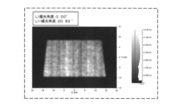
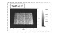
- FIGS. 8 to 11 illustrate simulation results conducted by the inventor of the present invention regarding brightness unevenness caused by the polarization state of the propagating light L11 described above.
- FIG. 8 shows an example of simulation results when the polarization state of the propagating light L11 is unstable.
- FIG. 9 shows an example of simulation results when the polarization state of the propagating light L11 is stable.
- FIG. 10 shows another example of the simulation results when the polarization state of the propagating light L11 is unstable.
- FIG. 11 shows another example of the simulation results when the polarization state of the propagating light L11 is stable.
- FIG. 8 a case is illustrated in which the image light L1 incident on the coupling region 21 has a polarization angle of "90.00°" with respect to S-polarized light, that is, it is S-polarized light.
- the initial polarization angle of the propagating light L11 in the first expansion region 23 was "20.83°". For this reason, the polarization state of the propagating light L11 deviates from the S-polarized light, etc., and as shown in FIG. 8, brightness unevenness was observed in the brightness distribution in the X direction corresponding to the horizontal direction of the virtual image Iv.
- the polarization angle of the image light L1 is set to "30.00°".
- the initial polarization angle of the propagating light L11 was "3.30°”
- the polarization state of the propagating light L11 was set to be near S polarization.
- FIG. 10 shows an example in which the polarization angle of the image light L1 incident on the coupling region 21 is "60.00°", and the polarization angle of the initial propagation light L11 is "42.04°".
- the polarization state of the propagating light L11 was significantly different from both the P-polarized light and the S-polarized light, uneven brightness was observed in the brightness distribution after the pupil dilation, as shown in FIG. For example, a change in brightness was observed for about three cycles in the X direction.
- the polarization angle of the image light L1 is set to "-88.00°".
- the initial polarization angle of the propagating light L11 was "89.91°”
- the polarization state of the propagating light L11 was set to be near P polarization.
- FIG. 12 illustrates the relationship between the diffraction pitch Gp2 and the diffraction efficiency in the first expansion region 23.
- FIG. 12 was obtained as a result of a numerical simulation of the diffraction efficiency when the polarization state of the propagating light L11 was changed in a state where various diffraction pitches Gp2 were set in the first expansion region 23.
- the wavelength ⁇ of the propagating light L11 is set to "0.52 ⁇ m”
- the thickness d between the main surfaces 13a and 13b of the light guide 13 is set to "5 ⁇ m”
- the refractive index n of the hologram material was set to "1.505”
- the refractive index modulation amount ⁇ n of the hologram was set to "0.02”.
- the relationship between the incident angle and the output angle at the diffraction position P1 of the first expansion region 23 is that in a diffraction structure in which the traveling direction of the incident light is the X direction and the output light is propagated in the Y direction, the incident angle and the output angle are the same.
- the size was set to change according to the diffraction pitch Gp2.
- the horizontal axis is the diffraction pitch [ ⁇ m]
- the vertical axis is the diffraction efficiency [%].
- Graph E1 shows the maximum value of diffraction efficiency in propagating light L11 whose polarization state has been changed.
- Graph E2 shows the minimum value of the diffraction efficiency in the propagating light L11 whose polarization state has been changed.
- the first expansion region 23 of this embodiment from the viewpoint of obtaining a relatively large diffraction power from the propagating light L11 propagating in the X direction to the divided light L12 propagating in the Y direction, the first expansion region 23 is 1.0 ⁇ /n [ ⁇ m ] It is possible to use the following diffraction pitch Gp2. Then, in the example of FIG. 12, a large discrepancy of 30% or more in diffraction efficiency occurs between the graph E1 of the maximum value of the diffraction efficiency and the graph E2 of the minimum value when the polarization state of the propagating light L11 changes. ing. Further, as the diffraction pitch Gp2 becomes narrower, the deviation in diffraction efficiency becomes larger.
- the polarization state of the propagating light L11 in the first expansion region 23 is unstable, there is a concern that brightness unevenness may occur.
- the polarization state of the propagating light L11 in the first extension region 23 is stabilized, so the diffraction pitch is narrow such as 1.0 ⁇ /n [ ⁇ m] or less. Even if Gp2 is used, brightness unevenness can be reduced. Further, in the first expansion region 23, it is also possible to easily obtain larger diffraction power by using a narrower diffraction pitch Gp2.
- the divided light L12 propagating in the Y direction within the light guide 13 is diffracted into duplicate light L13 that is emitted to the outside of the light guide 13 while being tilted in the Y direction.
- a relatively small degree of diffraction power is sufficient. Therefore, in the second expansion region 25 of this embodiment, a diffraction pitch Gp3 wider than the diffraction pitch Gp2 of the first expansion region 23 can be used.
- FIG. 13 illustrates the relationship between the diffraction pitch Gp3 and the diffraction efficiency in the second expansion region 23.
- the same numerical simulation as in FIG. 12 was performed for the second expansion region 25.
- the wavelength ⁇ of the split light L12, the thickness d of the light guide 13, and the refractive index n of the hologram material are set in the same way as in the case of FIG. 12, and the refractive index modulation amount ⁇ n of the hologram is 0. It was set to 03. Further, the incident angle at the diffraction position P2 of the second expansion region 25 is set to 45°, and the output angle is smaller than the critical angle of the light guide 13 and changes according to the diffraction pitch Gp3 in the output range. It was set to Graph F1 shows the maximum value of diffraction efficiency in divided light L12 whose polarization state has been changed. Graph F2 shows the minimum value of the diffraction efficiency in the divided light L12 whose polarization state has been changed.
- the diffraction pitch Gp3 of the second expansion region 25 is in the range of 1.23 ⁇ /n [ ⁇ m] or more and 10.0 ⁇ /n [ ⁇ m] or less. It was confirmed that it can be set within R1.
- the graph F1 of the maximum value of the diffraction efficiency of the split light L12 has a minimum value, so that when it falls below the lower limit value, it is due to a change in the polarization state. Fluctuations in diffraction efficiency become noticeable.
- the diffraction pitch Gp3 of the second expansion region 25 exceeds the lower limit value of the range R1, fluctuations in the diffraction efficiency due to changes in the polarization state of the divided light L12 in the second expansion region 25 can be reduced, and the virtual image Deterioration in IV image quality can be suppressed.
- the wider the diffraction pitch Gp3 the smaller the difference between the graph F1 of the maximum value and the graph F2 of the minimum value of the diffraction efficiency of the split light L12.
- the diffraction pitch Gp3 is 2.4 ⁇ m or less, it is advantageous in that fluctuations in diffraction efficiency due to changes in polarization state can be reduced to less than 1%.
- each of the graphs F1 and F2 of the diffraction efficiency of the divided light L12 has a range R2 in which the diffraction pitch Gp3 reaches its peak value in the vicinity of 1.4 ⁇ m to 2.0 ⁇ m. That is, when the diffraction pitch Gp3 is widened beyond the peak range R2, the diffraction efficiency decreases regardless of the polarization state. On the other hand, when the diffraction pitch Gp3 of the second expansion region 25 is less than the upper limit of the range R1, the diffraction efficiency of the divided light L12 can be ensured to be more than half of the peak value.
- the image display device 2 in this embodiment allows the virtual image Iv to be viewed as an example of an optical image, and includes the display section 11 and the light guide 13.
- the display unit 11 emits image light L1 that is visually recognized as a virtual image Iv.
- the light guide 13 guides the image light L1 from the display section 11 to the outside.
- the light guide 13 has a pair of principal surfaces 13a and 13b facing each other.
- the light guide 13 is provided with a coupling region 21, which is an example of an incident region, and first and second extension regions 23, which are each an example of an extension region.
- the image light L1 from the display section 11 is incident, and the image light L1 is diffracted so as to propagate inside the light guide 13 by reflection between the pair of main surfaces 13a and 13b.
- the first expansion region 23 diffracts the propagated image light L11 at a plurality of positions P1 where the image light propagates in the light guide 13, and outputs the diffracted image light L11 as a plurality of image lights.
- the image light L11 propagated to the first expansion area 23 is located on a plane (XZ plane) including the normal direction (Z direction) of the main surfaces 13a and 13b in the first expansion area 23 and the propagation direction (X direction) of the propagated light L11.
- the image light L1 incident on the coupling region 21 is polarized in the first polarization state so that it is near P polarization or near S polarization, as an example of the first polarization state polarized along the direction parallel or perpendicular to ). (See FIGS. 5(A) and 5(B)).
- the polarization state of the propagating light L11 in the first extension region 23 can be stabilized, fluctuations in diffraction efficiency can be reduced, and brightness unevenness can be reduced. In this way, fluctuations in image quality in the image display device 2 that makes the virtual image Iv visible can be suppressed.
- the propagation direction of the propagation light L11 is defined, for example, by the direction of a light ray such as a central ray in the luminous flux of the propagation light L11. Further, the first polarization state may be specified from each of the principal planes 13a and 13b orthogonal to the above plane.
- the image light L1 enters the coupling region 21 at an angle oblique to the normal direction (Z direction) of the main surfaces 13a and 13b and propagates inside the light guide 13.
- a bonding region 21 is provided so as to do so.
- the polarization state of the image light L1 that enters the coupling region 21 is set so that the image light L11 in the first expansion region 23 has a specific polarization state. Therefore, fluctuations in image quality in the image display device 2 can be suppressed.
- the inclination at which the image light L1 enters the coupling region 21 is between the first direction (X direction) in which the plurality of positions P1 are lined up in the first expansion region 23 and the main surfaces 13a and 13b. It is inclined in a second direction (Y direction) that intersects with a plane including the normal direction (Z direction).
- the plane of incidence of the image light L1 in the coupling region 21 is different from the plane of incidence of the propagating light L11 in the first extension region 23 (see FIG. 4).
- Luminance unevenness in the image display device 2 can be reduced by taking into consideration the shift in the polarization state of the propagating light L11 from the polarization state of the image light L1 due to such a difference in the incident plane.
- the extension region includes first and second extension regions 23 and 25 having diffraction pitches Gp2 and Gp3 that are different from each other.
- the diffraction pitch Gp2 of the first expansion region 23 is narrower than the diffraction pitch Gp3 of the second expansion region 25.
- the image light L1 that enters the coupling region 21 is set to the second polarization state so that the image light L11 propagated to the first extension region 23 becomes the first polarization state.
- the first extension region 23 is configured to guide light so as to diffract the image light L11 propagated from the coupling region 21 and output a plurality of image lights L12 to the second extension region 25. It is provided in the body 13. By stabilizing the polarization state in the first extension region 23 near the combination region 21 among the plurality of extension regions 23 and 25, fluctuations in the image quality of the virtual image Iv due to brightness unevenness can be easily suppressed.
- the diffraction pitch Gp3 in the second expansion region 25 is 1.23 ⁇ /n or more using the wavelength ⁇ of the image light L1 and the refractive index n in the light guide 13. Moreover, it is 10.0 ⁇ /n or less. According to such a relatively wide diffraction pitch Gp3, even if the polarization state in the second extension region 25 is unstable, fluctuations in diffraction efficiency can be suppressed, and the image quality in the image display device 2 can be improved.
- the first polarization state includes at least one of P-polarized light and S-polarized light.
- the first polarization state does not have to be exactly the same as the P-polarized light and the S-polarized light, and can be appropriately set within an acceptable error range. By using such a first polarization state, fluctuations in image quality in the image display device 2 can be suppressed.
- the second polarization state has a polarization angle ⁇ that is obtained by rotating the polarization direction from P polarization or S polarization.
- the second polarization state is a polarization state different from P-polarization and S-polarization.
- the second polarization state is linearly polarized light that is different from P and S polarized light.
- the second polarization state can also be set as appropriate within the tolerance range. By setting such a second polarization state, fluctuations in image quality in the image display device 2 can be suppressed.
- the second polarization state may be circularly polarized light or elliptically polarized light.
- the image display device 2 may further include a polarization setting section 14.
- the polarization setting section 14 is disposed between the display section 11 and the light guide 13, and sets the image light L1 entering the coupling region 21 from the display section 11 to a second polarization state. By setting the second polarization state by the polarization setting unit 14, fluctuations in image quality in the image display device 2 can be suppressed.
- the polarization setting unit 14 includes, for example, at least one of a half-wave plate, a quarter-wave plate, and a polarizing plate.
- the display section 11 may be arranged so that the display section 11 emits image light to the light guide 13 in the second polarization state. Even with this arrangement of the display section 11, fluctuations in image quality in the image display device 2 can be suppressed by setting the second polarization state.
- the light guide 13 is arranged so as to guide the image light from the display section 11 to the light-transmitting member.
- the image display device 2 constitutes a head-up display that displays a virtual image Iv in the HUD system 1 through a transparent member such as a windshield 5.
- the image display device 2 of this embodiment can suppress fluctuations in the image quality of the virtual image Iv in the HUD system 1.
- the optical system 20 of this embodiment includes a light guide 13 and a polarization setting section 14.
- the light guide 13 guides the image light L1 from the display unit 11, which emits the image light L1 visually recognized as the virtual image Iv, to the outside.
- the polarization setting section 14 is arranged between the display section 11 and the light guide 13.
- the light guide 13 has a pair of main surfaces 13a and 13b facing each other.
- the light guide 13 includes an incident area for diffracting the image light and a light guide so that the image light from the display section 11 enters and propagates inside the light guide 13 by reflection between a pair of main surfaces.
- extension regions are provided that diffract the propagated image light and emit the image light as a plurality of image lights.
- the polarization setting unit 14 is configured to polarize the image light propagated to the expansion area along a direction parallel or perpendicular to a plane including the normal direction of the main surface in the expansion area and the propagation direction of the propagated image light.
- the image light incident on the incident region is set to a second polarization state different from the first polarization state so that the image light is in the first polarization state.
- Embodiment 1 has been described as an example of the technology disclosed in this application.
- the technology in the present disclosure is not limited to this, and can also be applied to embodiments in which changes, substitutions, additions, omissions, etc. are made as appropriate.
- Embodiment 1 described above describes a configuration example in which the first extension region 23 is arranged on the +X side of the coupling region 21 in the light guide 13, and the second extension region 25 is arranged on the +Y side of the first extension region 23. did.
- the arrangement of the regions 21, 23, and 25 is not limited to the above configuration example.
- the first extension region 23 is arranged on the +Y side of the coupling region 21, and the first extension region 23
- the second expansion region 25 may be arranged on the +X side of the second expansion region 25 .
- polarization control is performed to stabilize the polarization state of the image light propagating toward the narrower diffraction pitch of the two extended regions 23 and 25 arranged as described above. May be done.
- the number of expansion regions provided in the light guide 13 is not limited to two, but may be one, or three or more.
- the image display device in which the image light L1 incident on the light guide 13 and the image light L2 emitted from the light guide 13 are tilted in the Y direction with respect to the normal line of the light guide 13. 2 was explained.
- the image lights L1 and L2 do not need to be tilted as described above, and may be tilted in a direction different from the Y direction, for example. Further, one or both of the image lights L1 and L2 may be parallel to the normal line of the light guide 13.
- the HUD system 1 applied to the vehicle 3 has been described, but the object to which the HUD system 1 is applied is not limited to the vehicle 3 in this embodiment.
- the object of the HUD system 1 in this embodiment may be various types of moving objects such as trains, motorcycles, ships, and airplanes, or may be an amusement machine or the like without a moving object.
- the image display device 2 of this embodiment may be arranged so as to emit the image light L2 to a transparent member provided on various objects in the HUD system 1.
- the image display device 2 and the optical system 20 that make the virtual image Iv visible as an example of an optical image have been described.
- the optical image displayed by the image display device 2 is not limited to the virtual image Iv, but may be a real image, for example.
- the image display device 2 of the present embodiment is configured such that a real image is formed between a transparent member such as the windshield 5 and the viewer D using the pupil expansion type optical system 20 similar to that described above. may be done. Displaying such a real image is useful, for example, in amusement applications.
- the image display device 2 included in the HUD system 1 has been described, but the image display device 2 does not need to be included in the HUD system 1 in this embodiment.
- the image display device 2 may be any of various image display devices that display an optical image such as a virtual image or a real image such as an HMD or an electronic mirror.
- a first aspect of the present disclosure is an image display device for visually recognizing an optical image, which includes a display section that emits image light that is visually recognized as an optical image, and a guide that guides the image light from the display section to the outside.
- a light body is provided.
- the light guide has a pair of main surfaces facing each other. In the light guide, the image light from the display section is incident and propagated inside the light guide by reflection between a pair of main surfaces. At a plurality of positions where the light propagates, extension regions are provided that diffract the propagated image light and emit the image light as a plurality of image lights.
- the image light propagated to the expansion area becomes a first polarization state in which it is polarized along a direction parallel or perpendicular to a plane including the normal direction of the main surface in the expansion area and the propagation direction of the propagated image light.
- the image light incident on the incident region is set to a second polarization state different from the first polarization state.
- the image light is incident at an angle oblique to the normal direction of the principal surface in the incident region and propagates inside the light guide.
- An entrance region is provided.
- the inclination at which the image light is incident in the incident area is a plane that includes a first direction in which the plurality of positions are lined up in the extended area and a normal direction of the main surface. is tilted in a second direction intersecting with .
- the extension region includes first and second extension regions having different diffraction pitches.
- the diffraction pitch of the first extension region is narrower than the diffraction pitch of the second extension region.
- the image light incident on the incident region is set to the second polarization state so that the image light propagated to the first expansion region is in the first polarization state.
- the first extension region diffracts the image light propagated from the incident region and guides the plurality of image lights to the second extension region. Provided on the light body.
- the diffraction pitch in the second extension region is 1.23 ⁇ using the wavelength ⁇ of the image light and the refractive index n in the light guide. It is not less than ⁇ /n and not more than 10.0 ⁇ /n.
- the first polarization state includes one of P-polarized light and S-polarized light.
- the second polarization state includes P-polarized light and S-polarized light having a polarization angle obtained by rotating the polarization direction from P-polarized light or S-polarized light. It is a different polarized light.
- the image display device is disposed between a display section and a light guide, and transmits image light incident from the display section to the incident area. It further includes a polarization setting section that sets the polarization state.
- the polarization setting section includes at least one of a half-wave plate, a quarter-wave plate, and a polarizing plate.
- the display section is arranged so that the display section emits image light to the light guide in the second polarization state.
- the light guide is arranged to guide image light from the display section to the light-transmitting member, and A head-up display that displays a virtual image is constructed using
- a thirteenth aspect includes a light guide that guides image light from a display section that emits image light that is visually recognized as an optical image to the outside, and a polarization setting section that is disposed between the display section and the light guide. It is an optical system equipped with.
- the light guide has a pair of main surfaces facing each other. In the light guide, the image light from the display section is incident and propagated inside the light guide by reflection between a pair of main surfaces. At a plurality of positions where the light propagates, extension regions are provided that diffract the propagated image light and emit the image light as a plurality of image lights.
- the polarization setting unit includes a first polarization unit in which the image light propagated to the expansion area is polarized along a direction parallel or perpendicular to a plane including the normal direction of the main surface in the expansion area and the propagation direction of the propagated image light.
- the image light incident on the incident region is set to a second polarization state different from the first polarization state so that the image light has a polarization state of .
- the optical system of the thirteenth aspect has the characteristics of any one of the second to tenth aspects.
- the present disclosure is applicable to an image display device that allows an observer to visually recognize an optical image, and is applicable to, for example, a HUD, an HMD, an electronic mirror, and the like.
Landscapes
- Physics & Mathematics (AREA)
- General Physics & Mathematics (AREA)
- Optics & Photonics (AREA)
- Engineering & Computer Science (AREA)
- Chemical & Material Sciences (AREA)
- Combustion & Propulsion (AREA)
- Transportation (AREA)
- Mechanical Engineering (AREA)
- Diffracting Gratings Or Hologram Optical Elements (AREA)
- Instrument Panels (AREA)
Priority Applications (4)
| Application Number | Priority Date | Filing Date | Title |
|---|---|---|---|
| JP2024530296A JPWO2024004287A1 (https=) | 2022-06-29 | 2023-03-16 | |
| CN202380050118.2A CN119452291A (zh) | 2022-06-29 | 2023-03-16 | 图像显示装置以及光学系统 |
| EP23830741.7A EP4550026A4 (en) | 2022-06-29 | 2023-03-16 | IMAGE DISPLAY DEVICE AND OPTICAL SYSTEM |
| US18/984,039 US20250130424A1 (en) | 2022-06-29 | 2024-12-17 | Image display device and optical system |
Applications Claiming Priority (2)
| Application Number | Priority Date | Filing Date | Title |
|---|---|---|---|
| JP2022-104930 | 2022-06-29 | ||
| JP2022104930 | 2022-06-29 |
Related Child Applications (1)
| Application Number | Title | Priority Date | Filing Date |
|---|---|---|---|
| US18/984,039 Continuation US20250130424A1 (en) | 2022-06-29 | 2024-12-17 | Image display device and optical system |
Publications (1)
| Publication Number | Publication Date |
|---|---|
| WO2024004287A1 true WO2024004287A1 (ja) | 2024-01-04 |
Family
ID=89381968
Family Applications (1)
| Application Number | Title | Priority Date | Filing Date |
|---|---|---|---|
| PCT/JP2023/010413 Ceased WO2024004287A1 (ja) | 2022-06-29 | 2023-03-16 | 画像表示装置、及び光学系 |
Country Status (5)
| Country | Link |
|---|---|
| US (1) | US20250130424A1 (https=) |
| EP (1) | EP4550026A4 (https=) |
| JP (1) | JPWO2024004287A1 (https=) |
| CN (1) | CN119452291A (https=) |
| WO (1) | WO2024004287A1 (https=) |
Citations (6)
| Publication number | Priority date | Publication date | Assignee | Title |
|---|---|---|---|---|
| US20060215244A1 (en) * | 2003-12-02 | 2006-09-28 | Jacob Yosha | Vehicle display system |
| JP2014132328A (ja) * | 2012-11-16 | 2014-07-17 | Rockwell Collins Inc | 透明導波管ディスプレイ |
| US9946072B2 (en) | 2015-10-29 | 2018-04-17 | Microsoft Technology Licensing, Llc | Diffractive optical element with uncoupled grating structures |
| US20200057304A1 (en) * | 2018-08-16 | 2020-02-20 | Facebook Technologies, Llc | Transmission improvement for flat lens based ar/vr glasses |
| US20210199970A1 (en) * | 2019-12-30 | 2021-07-01 | Facebook Technologies, Llc | Optical system and method for providing compressed eyebox |
| JP2021531498A (ja) * | 2018-07-16 | 2021-11-18 | ルムス エルティーディー. | 偏光された内部反射体を採用する導光光学素子 |
Family Cites Families (2)
| Publication number | Priority date | Publication date | Assignee | Title |
|---|---|---|---|---|
| GB201117029D0 (en) * | 2011-10-04 | 2011-11-16 | Bae Systems Plc | Optical waveguide and display device |
| CN114428376B (zh) * | 2021-12-29 | 2024-07-02 | 歌尔股份有限公司 | 光波导系统及增强现实设备 |
-
2023
- 2023-03-16 CN CN202380050118.2A patent/CN119452291A/zh active Pending
- 2023-03-16 JP JP2024530296A patent/JPWO2024004287A1/ja active Pending
- 2023-03-16 WO PCT/JP2023/010413 patent/WO2024004287A1/ja not_active Ceased
- 2023-03-16 EP EP23830741.7A patent/EP4550026A4/en active Pending
-
2024
- 2024-12-17 US US18/984,039 patent/US20250130424A1/en active Pending
Patent Citations (6)
| Publication number | Priority date | Publication date | Assignee | Title |
|---|---|---|---|---|
| US20060215244A1 (en) * | 2003-12-02 | 2006-09-28 | Jacob Yosha | Vehicle display system |
| JP2014132328A (ja) * | 2012-11-16 | 2014-07-17 | Rockwell Collins Inc | 透明導波管ディスプレイ |
| US9946072B2 (en) | 2015-10-29 | 2018-04-17 | Microsoft Technology Licensing, Llc | Diffractive optical element with uncoupled grating structures |
| JP2021531498A (ja) * | 2018-07-16 | 2021-11-18 | ルムス エルティーディー. | 偏光された内部反射体を採用する導光光学素子 |
| US20200057304A1 (en) * | 2018-08-16 | 2020-02-20 | Facebook Technologies, Llc | Transmission improvement for flat lens based ar/vr glasses |
| US20210199970A1 (en) * | 2019-12-30 | 2021-07-01 | Facebook Technologies, Llc | Optical system and method for providing compressed eyebox |
Non-Patent Citations (1)
| Title |
|---|
| See also references of EP4550026A4 |
Also Published As
| Publication number | Publication date |
|---|---|
| JPWO2024004287A1 (https=) | 2024-01-04 |
| US20250130424A1 (en) | 2025-04-24 |
| CN119452291A (zh) | 2025-02-14 |
| EP4550026A4 (en) | 2025-10-08 |
| EP4550026A1 (en) | 2025-05-07 |
Similar Documents
| Publication | Publication Date | Title |
|---|---|---|
| JP7210406B2 (ja) | 導光板、導光板の製造装置、導光板の製造方法、及び、それを用いた映像表示装置 | |
| JP5950233B2 (ja) | シースルーディスプレイ装置及びシースルーディスプレイ装置を搭載した車両 | |
| CN108474958B (zh) | 用于减少头戴式显示器中的重像的系统和方法 | |
| JP6225474B2 (ja) | 表示装置 | |
| JP6265805B2 (ja) | 画像表示装置 | |
| TWI724732B (zh) | 波導裝置及光學引擎 | |
| US20230176382A1 (en) | Waveguide display with cross-polarized eye pupil expanders | |
| US11009701B2 (en) | Display apparatus and method for driving the same | |
| JP7804865B2 (ja) | 画像表示装置及びヘッドアップディスプレイシステム | |
| US20250116860A1 (en) | Optical system and image display device | |
| WO2024004287A1 (ja) | 画像表示装置、及び光学系 | |
| US12554134B2 (en) | Head-up display system | |
| EP4050401A1 (en) | Optical system and mixed reality device | |
| CN112612138B (zh) | 一种波导显示系统 | |
| JP7784640B2 (ja) | 光学系及びそれを備えたヘッドアップディスプレイシステム | |
| JP7836987B2 (ja) | 光学系及びそれを備えたヘッドアップディスプレイシステム | |
| WO2023188720A1 (ja) | 光学系及びそれを備えたヘッドアップディスプレイシステム | |
| JP2023070440A (ja) | 回折素子及びそれを備えた光学系、ヘッドアップディスプレイシステム | |
| CN117761825A (zh) | 一种光波导器件及ar显示装置 | |
| WO2025023933A1 (en) | Hybrid reflective and diffractive waveguide architecture |
Legal Events
| Date | Code | Title | Description |
|---|---|---|---|
| 121 | Ep: the epo has been informed by wipo that ep was designated in this application |
Ref document number: 23830741 Country of ref document: EP Kind code of ref document: A1 |
|
| WWE | Wipo information: entry into national phase |
Ref document number: 2024530296 Country of ref document: JP |
|
| WWE | Wipo information: entry into national phase |
Ref document number: 202380050118.2 Country of ref document: CN |
|
| WWE | Wipo information: entry into national phase |
Ref document number: 2023830741 Country of ref document: EP |
|
| NENP | Non-entry into the national phase |
Ref country code: DE |
|
| ENP | Entry into the national phase |
Ref document number: 2023830741 Country of ref document: EP Effective date: 20250129 |
|
| WWP | Wipo information: published in national office |
Ref document number: 202380050118.2 Country of ref document: CN |
|
| WWP | Wipo information: published in national office |
Ref document number: 2023830741 Country of ref document: EP |