WO2024004287A1 - Image display device and optical system - Google Patents
Image display device and optical system Download PDFInfo
- Publication number
- WO2024004287A1 WO2024004287A1 PCT/JP2023/010413 JP2023010413W WO2024004287A1 WO 2024004287 A1 WO2024004287 A1 WO 2024004287A1 JP 2023010413 W JP2023010413 W JP 2023010413W WO 2024004287 A1 WO2024004287 A1 WO 2024004287A1
- Authority
- WO
- WIPO (PCT)
- Prior art keywords
- light
- image
- display device
- polarization state
- light guide
- Prior art date
Links
- 230000003287 optical effect Effects 0.000 title claims abstract description 48
- 230000000644 propagated effect Effects 0.000 claims abstract description 40
- 230000010287 polarization Effects 0.000 claims description 257
- 239000011295 pitch Substances 0.000 claims description 47
- 230000001902 propagating effect Effects 0.000 abstract description 87
- 230000008878 coupling Effects 0.000 description 45
- 238000010168 coupling process Methods 0.000 description 45
- 238000005859 coupling reaction Methods 0.000 description 45
- 238000004088 simulation Methods 0.000 description 17
- 210000001747 pupil Anatomy 0.000 description 15
- 238000010586 diagram Methods 0.000 description 13
- 230000010344 pupil dilation Effects 0.000 description 11
- 238000005516 engineering process Methods 0.000 description 6
- 230000010076 replication Effects 0.000 description 6
- 230000004907 flux Effects 0.000 description 3
- 230000006870 function Effects 0.000 description 3
- 239000000463 material Substances 0.000 description 3
- 238000007792 addition Methods 0.000 description 2
- 239000003086 colorant Substances 0.000 description 2
- 230000005684 electric field Effects 0.000 description 2
- 239000004973 liquid crystal related substance Substances 0.000 description 2
- 230000000737 periodic effect Effects 0.000 description 2
- 230000000087 stabilizing effect Effects 0.000 description 2
- 238000006467 substitution reaction Methods 0.000 description 2
- 238000004364 calculation method Methods 0.000 description 1
- 238000006243 chemical reaction Methods 0.000 description 1
- 230000007423 decrease Effects 0.000 description 1
- 230000006866 deterioration Effects 0.000 description 1
- 230000000694 effects Effects 0.000 description 1
- 239000011521 glass Substances 0.000 description 1
- 239000011347 resin Substances 0.000 description 1
- 229920005989 resin Polymers 0.000 description 1
- 239000004065 semiconductor Substances 0.000 description 1
- 229910052710 silicon Inorganic materials 0.000 description 1
- 239000010703 silicon Substances 0.000 description 1
Images


Classifications
-
- B—PERFORMING OPERATIONS; TRANSPORTING
- B60—VEHICLES IN GENERAL
- B60K—ARRANGEMENT OR MOUNTING OF PROPULSION UNITS OR OF TRANSMISSIONS IN VEHICLES; ARRANGEMENT OR MOUNTING OF PLURAL DIVERSE PRIME-MOVERS IN VEHICLES; AUXILIARY DRIVES FOR VEHICLES; INSTRUMENTATION OR DASHBOARDS FOR VEHICLES; ARRANGEMENTS IN CONNECTION WITH COOLING, AIR INTAKE, GAS EXHAUST OR FUEL SUPPLY OF PROPULSION UNITS IN VEHICLES
- B60K35/00—Arrangement of adaptations of instruments
-
- G—PHYSICS
- G02—OPTICS
- G02B—OPTICAL ELEMENTS, SYSTEMS OR APPARATUS
- G02B27/00—Optical systems or apparatus not provided for by any of the groups G02B1/00 - G02B26/00, G02B30/00
- G02B27/01—Head-up displays
-
- G—PHYSICS
- G02—OPTICS
- G02B—OPTICAL ELEMENTS, SYSTEMS OR APPARATUS
- G02B5/00—Optical elements other than lenses
- G02B5/18—Diffraction gratings
Definitions
- the present disclosure relates to an image display device that allows an observer to view an optical image such as a virtual image, and an optical system used in the image display device.
- Patent Document 1 discloses an optical display system including a plurality of diffractive optical elements (DOE) for pupil dilation in a virtual reality or mixed reality head mounted display (HMD) device or the like.
- DOE diffractive optical elements
- HMD mixed reality head mounted display
- a main beam from an imager propagates from a first DOE to a second DOE, such as as a TM polarized beam or a TE polarized beam.
- the second DOE includes grating features configured to rotate the state of polarization of the optical perturbation.
- light interference is reduced by rotating the polarization of the perturbation beam to be orthogonal to the polarization of the main beam used for image display.
- the present disclosure provides an image display device and an optical system that can suppress fluctuations in image quality in an image display device that makes a virtual image visible.
- An image display device in the present disclosure is an image display device that allows an optical image to be viewed, and includes a display unit that emits image light that is viewed as an optical image, and a light guide that guides the image light from the display unit to the outside. Equipped with.
- the light guide has a pair of principal surfaces facing each other. In the light guide, the image light from the display section is incident and propagated inside the light guide by reflection between a pair of main surfaces. At a plurality of positions where the light propagates, extension regions are provided that diffract the propagated image light and emit the image light as a plurality of image lights.
- the image light propagated to the expansion area becomes a first polarization state in which it is polarized along a direction parallel or perpendicular to a plane including the normal direction of the main surface in the expansion area and the propagation direction of the propagated image light.
- the image light incident on the incident region is set to a second polarization state different from the first polarization state.
- the optical system in the present disclosure includes a light guide that guides image light from a display section that emits image light that is visually recognized as an optical image to the outside, and a polarization setting that is arranged between the display section and the light guide. It is equipped with a section.
- the light guide has a pair of main surfaces facing each other. In the light guide, the image light from the display section is incident and propagated inside the light guide by reflection between a pair of main surfaces. At a plurality of positions where the light propagates, extension regions are provided that diffract the propagated image light and emit the image light as a plurality of image lights.
- the polarization setting unit includes a first polarization unit in which the image light propagated to the expansion area is polarized along a direction parallel or perpendicular to a plane including the normal direction of the main surface in the expansion area and the propagation direction of the propagated image light.
- the image light incident on the incident region is set to a second polarization state different from the first polarization state so that the image light has a polarization state of .
- the image display device and optical system of the present disclosure it is possible to suppress fluctuations in image quality in the image display device that makes a virtual image visible.
- a diagram for explaining an overview of a head-up display system according to Embodiment 1 of the present disclosure A diagram illustrating the configuration of a head-up display system according to Embodiment 1.
- Diagram for explaining pupil dilation operation in the image display device of Embodiment 1 A diagram illustrating a polarization state in the image display device of Embodiment 1.
- Embodiment 1 of the present disclosure will be described below with reference to the drawings. In this embodiment, an example of a system to which a pupil expansion type image display device and optical system are applied will be described.
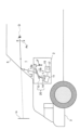
- FIG. 1 is a diagram for explaining an overview of a head-up display (HUD) system 1 according to the present embodiment.
- the HUD system 1 includes, for example, as shown in FIG. 1, an image display device 2 and a windshield 5.
- the HUD system 1 is a system that allows an observer D such as a passenger to visually recognize a virtual image Iv as an example of an optical image, for example in a vehicle 3 or the like in which a windshield 5 is provided.
- the area where the observer D's eyes are positioned so that the virtual image Iv becomes visible to the observer D is referred to as a visibility area Ac.
- the image display device 2 of this embodiment includes a display unit 11 that generates image light L1 that is visually recognized as a virtual image Iv, and a pupil (for example, an exit pupil) of the image light L1 from the display unit 11.
- the light guide 13 is expanded to guide the expanded image light L2 to the windshield 5. According to such a pupil expansion type image display device 2, it is easy to ensure a large viewing area Ac in the HUD system 1.
- the pupil dilation technology When the pupil dilation technology is applied to a HUD, there may be a problem that, for example, the brightness of the virtual image Iv changes when the observer D moves his or her eyes within the viewing area Ac, resulting in noticeable brightness unevenness and fluctuations in image quality. Therefore, in this embodiment, in order to solve the problem of such brightness unevenness and suppress fluctuations in image quality, a configuration is adopted in which polarization in the pupil expansion type image display device 2 is controlled. The configuration of the image display device 2 in the HUD system 1 of this embodiment will be described below.
- FIG. 2 illustrates the configuration of the HUD system 1 according to this embodiment.
- the image display device 2 is arranged, for example, inside a dashboard (not shown) below the windshield 5 of the vehicle 3.
- the image display device 2 of this embodiment includes a display section 11, a light guide 13, a polarization setting section 14, and a control section 15, as shown in FIG. 2, for example.
- the optical system 20 composed of the light guide 13 and the polarization setting section 14 is an example of an optical system in the image display device 2 of this embodiment.
- the windshield 5 is an example of a light-transmitting member provided on a moving object such as the vehicle 3.
- the light-transmitting member of the HUD system 1 is not limited to the windshield 5, and may be any of various members having light-transmitting properties in the visible light region, such as a combiner.
- the display unit 11 is a display element that has a display surface that displays an image using, for example, a plurality of pixels, and that generates image light L1 that represents the image on the display surface.
- the display unit 11 includes a liquid crystal display, an organic light-emitting diode (organic light-emitting diode) display, an LCOS (liquid crystal on silicon), a DMD (digital mirror device), a micro LED, or a scanning MEMS mirror.
- the display unit 11 does not need to have a display surface inside.
- a display surface such as a screen may be provided outside the display unit 11.
- the display unit 11 may include various light sources such as a laser light source or an LED light source that emit light in a single color or multiple colors to generate the image light L1.
- the image light L1 is composed of a light beam having a divergence angle corresponding to the angle of view of the image, for example.
- the optical paths of light rays such as the central ray are illustrated as appropriate in the drawings.
- the light guide 13 is a light guide member that is formed of a material that is transparent in the visible light region and is configured to allow total internal reflection of incident light.
- the light guide 13 has a pair of principal surfaces 13a and 13b facing each other.
- the light guide 13 is not limited to a planar shape, but may have a curved shape. Below, a configuration example of the light guide 13 having a planar shape in which the first main surface 13a and the second main surface 13b are parallel will be described.
- the image display device 2 may include a plurality of light guides 13. For example, light guides 13 for different colors of RGB may be used.
- the light guide 13 is composed of, for example, a glass or resin plate whose main surfaces 13a and 13b are mirror-finished.
- the normal direction of the main surfaces 13a and 13b of the light guide 13 will be referred to as the Z direction
- the two directions parallel to the main surfaces 13a and 13b and orthogonal to each other will be referred to as the X and Y directions.
- the X direction corresponds to the horizontal direction of the virtual image Iv
- the Y direction corresponds to the vertical direction of the virtual image Iv.
- the light guide 13 is arranged in the vehicle 3, for example, with the first principal surface 13a on the -Z side facing downward and the second principal surface 13b on the +Z side facing upward.
- the light guide 13 is arranged at an angle in the vehicle 3 as shown in FIG. 2, for example, according to various arrangement restrictions.
- the arrangement constraints of the light guide 13 are, for example, to prevent reflected light when sunlight or the like from outside the vehicle 3 enters the light guide 13 through the windshield 5 from reaching the visibility area Ac. be.
- the light guide 13 allows the image light L1 incident from the display section 11 on the -Z side and the image light L2 emitted to the windshield 5 on the +Z side to be directed to each main surface 13a. , 13b, respectively, so as to be inclined in the Y direction.
- the light guide 13 is provided with a diffraction structure for realizing the pupil dilation operation. Details of the configuration of the light guide 13 will be described later.
- the polarization setting unit 14 is composed of various optical elements disposed between the display unit 11 and the light guide 13, for example, and sets the image light L1 entering the light guide 13 from the display unit 11 into a specific polarization state. Set.
- the polarization setting unit 14 includes one or more optical elements of a half-wave plate, a quarter-wave plate, and a polarizing plate.
- the polarization setting section 14 may be incorporated into various optical systems such as a collimator provided between the display section 11 and the light guide 13, or may be configured integrally with the display section 11 or the light guide 13. good.
- the image display device 2 does not need to include an optical element as the polarization setting section 14.
- the function of the polarization setting unit 14 is to rotate the image light L1 in the optical axis direction. This may be realized by alignment with the light guide 13.
- the control unit 15 controls the entire operation of the image display device 2, for example.
- the control unit 15 can be realized by a circuit made up of semiconductor elements or the like.
- the control unit 15 can be configured with, for example, a microcomputer, CPU, MPU, GPU, DSP, FPGA, or ASIC.
- the control unit 15 realizes predetermined functions by reading data and programs stored in an internal memory or the like and performing various arithmetic operations.
- the control unit 15 also includes a storage device 17 such as an internal memory.
- the control unit 15 may be an external component of the image display device 2.
- the storage device 17 is a storage medium that stores programs and data necessary to realize the functions of the control unit 15.
- the storage device 17 can be realized by, for example, a hard disk (HDD), SSD, RAM, DRAM, ferroelectric memory, flash memory, magnetic disk, or a combination thereof.
- the storage device 17 stores a plurality of image data representing the virtual image Iv.
- the storage device 17 stores image content data for displaying various information on the display unit 11, such as a road progress guide display, the distance to the vehicle in front, the remaining battery level of the car, and the current vehicle speed.
- the storage device 17 is not limited to the internal memory of the control unit 15, but may be an external configuration of the control unit 15.
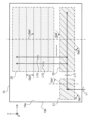
- FIG. 3 is a plan view showing an example of the configuration of the light guide 13 in the image display device 2. As shown in FIG.
- the light guide 13 includes a coupling region 21, a first expansion region 23, and a second expansion region 25, as shown in FIG. 3, for example.
- Each of the regions 21, 23, and 25 constitutes a diffraction structure element by providing a diffraction structure for realizing each diffraction power in the light guide 13.
- the first extension region 23 is arranged on the +X side of the coupling region 21, and the second extension region 25 is arranged on the +Y side of the first extension region 23.
- the diffraction structures of the regions 21, 23, and 25 in the light guide 13 can be configured with various periodic structures that can realize light diffraction, such as a volume hologram or a diffraction grating.
- a configuration example in which each diffraction structure of the light guide 13 is provided by a volume hologram between the first and second main surfaces 13a and 13b will be described.
- the volume hologram is composed of a periodic refractive index distribution within a dielectric film, such as interference fringes formed inside the light guide 13, for example.
- each region 21, 23, 25 may be a three-dimensional region in the light guide 13, respectively.
- the coupling region 21 is an example of an incident region that diffracts the incident image light L1 so as to optically couple with the image light L1 from the display section 11 in the light guide 13.
- the optical coupling is a state in which the light incident on the coupling region 21 satisfies the total internal reflection condition and propagates inside the light guide 13.
- the coupling region 21 has a diffraction power for converting the direction of the incident image light L1 into the image light L11 (hereinafter also referred to as "propagating light L11") that propagates in the X direction toward the first extension region 23. is set.
- the diffraction structure of the coupling region 21 has a diffraction pitch Gp1 and an inclination angle Ga1 for realizing the above-mentioned diffraction power.
- the diffraction pitch Gp1 indicates the period of the diffraction structure, such as the period of interference fringes in a hologram.
- the inclination angle Ga1 indicates, for example, the inclination of the direction in which the interference fringes extend with respect to a predetermined reference direction (for example, the Y direction). For example, in the example shown in FIG.
- the direction in which the image light L1 enters from the display unit 11 is inclined from the Z direction of the normal line to the coupling region 21 to the ⁇ Y side, so that the negative value (( In other words, an inclination angle Ga1 (clockwise) is set.
- the first expansion region 23 is a region in which diffraction is performed to expand the image light L11 (i.e., the propagation light L11) propagating by total reflection between the main surfaces 13a and 13b of the light guide 13 in the first propagation direction. .
- the expansion of the image light L11 is performed by dividing and duplicating the light beam of the image light L11 by diffraction a plurality of times, and emitting a plurality of light beams of the image light L12.
- the image light L12 of each light beam divided at this time is also referred to as "divided light L12" hereinafter.
- each divided light L12 after diffracted from the propagating light L11 having the X direction as the first propagation direction is transferred to the first expansion region 23 in the Y direction as the second propagation direction.
- the diffraction power for outputting to the second expansion region 25 is set toward.
- the diffraction structure of the first expansion region 23 has a diffraction pitch Gp2 and an inclination angle Ga2 to achieve relatively large diffraction power as described above.
- the diffraction pitch Gp2 of the first expansion region 23 is narrower than the diffraction pitch Gp1 of the coupling region 21, for example.
- the inclination angle Ga2 of the diffraction structure of the first expansion region 23 has a negative value, for example, like the inclination angle Ga1 of the diffraction structure of the coupling region 21, and is, for example, a larger angle than the inclination angle Ga1.
- the second expansion region 25 is a region where diffraction is performed to expand the propagating image light L12 in a second propagation direction intersecting the first propagation direction.
- the first and second propagation directions are not limited to the X and Y directions, but only need to intersect with each other, and do not need to be perpendicular to each other.
- the image light L12 is expanded in the second propagation direction in the second expansion region 25, the image light of each light beam that is divided and duplicated is hereinafter also referred to as "duplicated light" (not shown in FIG. 3).
- the duplicate light beams of the plurality of light beams constitute image light L2 as an expansion result (see FIG. 4).
- the duplicate light after being diffracted from the image light L12 that is totally reflected inside the light guide 13 while propagating in the Y direction does not satisfy the total reflection condition and is emitted to the outside.
- the diffraction power is set (see Figure 4). Since the diffraction power of the second extension region 25 is smaller than the diffraction power of the first extension region 23 described above, the diffraction pitch Gp3 of the second extension region 25 is, for example, smaller than the diffraction pitch Gp2 of the first extension region 23. wide. Further, the diffraction structure of the second expansion region 25 has, for example, an inclination angle Ga3 that is perpendicular to the second propagation direction (Y direction) and extends in the first propagation direction (X direction).
- the light guide 13 is not limited to the above configuration example, and various configurations can be adopted.
- the diffraction structure of each region 21, 23, 25 in the light guide 13 is not limited to a volume hologram, but may be composed of a diffraction grating or the like.
- the diffraction structures of each region 21, 23, 25 may be provided on the first or second main surface 13a, 14b of the light guide 13.
- each region 21, 23, 25 is not particularly limited to this, and may be inclined in various planes including the Z direction, for example.
- the control unit 15 of the image display device 2 determines the virtual image Iv to be displayed based on various information such as the driving environment acquired within the vehicle 3, for example.
- the control unit 15 reads the image data of the determined virtual image Iv from the storage device 17 and outputs it to the display unit 11.
- the display section 11 generates image light L1 representing an image under the control of the control section 15, and emits the generated image light L1.
- the image light L1 from the display section 11 enters the coupling region 21 of the light guide 13 in a state where the polarization setting section 14 sets a specific polarization state, for example.
- the incident image light L1 is two-dimensionally divided and duplicated by the pupil dilation operation in the first and second expansion regions 23 and 25 (details will be described later).
- the image light L2 expanded in this way is emitted from the light guide 13 to the windshield 5.
- the image light L2 incident on the windshield 5 is reflected and projected onto the viewing area Ac.
- the observer D can recognize the image light L2 projected from the HUD system 1 as a virtual image Iv by positioning his/her eyes in the viewing area Ac.
- the HUD system 1 displays the virtual image Iv superimposed on the real scene visible through the windshield 5.
- the image light L2 including a plurality of replication results is projected onto the viewing area Ac, so that even if the position of the eyes of the observer D shifts, as long as it is within the viewing area Ac, the viewer D can see the virtual image. Iv can be visually recognized.
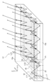
- FIG. 4 is a perspective view of the light guide 13 of the image display device 2, illustrating optical paths such as the center rays of various image lights L1, L11 to L13, and L2.
- the image light L1 from the display section 11 is directed from the second principal surface 13b of the light guide 13 in the Z direction of the normal in the polarization state set by the polarization setting section 14, for example.
- the light enters the light guide 13 at an angle in the Y direction.
- the incident image light L1 is refracted, for example, at the light guide 13 and reaches the diffraction structure of the coupling region 21. Note that when the diffraction structure of the coupling region 21 is provided on the second main surface 13b, the image light L1 enters the diffraction structure of the coupling region 21 before being refracted at the light guide 13.
- the diffraction structure of the coupling region 21 diffracts the image light L1 so as to optically couple with the incident image light L1.
- the diffracted image light L11 of the coupling region 21 is direction-changed into propagation light L11 that propagates in the X direction toward the first extension region 23. Due to the diffraction in the coupling region 21, the propagating light L11 is completely reflected in the Fresnel reflection of the light guide 13 with respect to the normal (Z direction) of each principal surface 13a, 13b in the first extension region 23 of the light guide 13, for example.
- the incident angle ⁇ 1 is greater than or equal to the critical angle, which is the minimum angle at which reflection occurs.
- the propagating light L11 from the coupling region 21 propagates in the X direction every time it is reflected between the first and second main surfaces 13a and 13b of the light guide 13 in the first extension region 23. passes through a plurality of positions P1 lined up in the X direction in the diffraction structure.
- FIG. 4 illustrates four diffraction positions P1 in the first expansion region 23, the number of diffraction positions P1 is not particularly limited.
- the passing position from the -Z side to the +Z side is the diffraction position P1, but in addition to or instead of this, the passing position from the +Z side to the -Z side is the diffraction position P1. There may be.
- the diffraction structure of the first extension region 23 is such that a part of the propagating light L11 is split into split light L12 at each diffraction position P1, and the split light L12 propagates in the Y direction toward the second extension region 25. , sequentially diffract the propagating light L11.
- the image light L1 can be expanded in the X direction by the plurality of divided beams L12 lined up in the X direction, which are divided and duplicated from the propagating light L11 in the first expansion region 23.
- the divided light L12 is, for example, at a critical angle of the light guide 13 with respect to the normal (Z direction) of each main surface 13a, 13b of the light guide 13 in the second expansion region 25.
- the angle of incidence is greater than or equal to the angle of incidence.
- the plurality of divided beams L12 from the first expansion region 23 are repeatedly reflected within the light guide 13 during propagation in the Y direction, so that they each reach a plurality of positions P2 arranged in the Y direction in the second expansion region 25. pass.
- three diffraction positions P2 are illustrated for one divided light L12, but the number of diffraction positions P2 is not particularly limited.
- the diffraction structure of the second expansion region 25 is such that at each diffraction position P3, a part of each divided light L12 is further divided and emitted to the outside of the light guide 13 as duplicated light L13 indicating the result of divided duplication. , each of the divided beams L12 is sequentially diffracted. In this way, the image light L1 can be expanded in the Y direction by the plurality of duplicate lights L13 arranged in the Y direction, which are obtained for each divided light beam L12 in the second expansion region 25.
- the duplicated light L13 Due to the effect of pupil expansion in two directions in the first and second expansion regions 23 and 25, image light L2 expanded in the X and Y directions is obtained. Due to the diffraction in the second expansion region 25, the duplicated light L13 has an angle less than the critical angle of the light guide 13 with respect to the normal (Z direction) to the first main surface 13a of the light guide 13 in the second expansion region 25, for example. has an angle of incidence of
- the luminous flux of the image light L1 from the display section 11 is diffracted in the first and second expansion regions 23 and 25 of the light guide 13. This can be expanded to a luminous flux of image light L2 including a plurality of duplicate lights L13 copied by.
- FIGS. 5A to 5C are graphs illustrating the polarization state in the image display device 2 of this embodiment.
- the horizontal axis of each graph corresponds to P-polarized light
- the vertical axis corresponds to S-polarized light.
- P-polarized light is a polarized state of linearly polarized light in which the direction of the electric field of light is parallel to the incident plane
- S-polarized light is a polarized state of linearly polarized light in which the direction of the electric field is perpendicular to the incident plane.
- the plane of incidence is a plane defined parallel to the light ray direction before and after the light is incident.
- FIG. 5(A) illustrates the polarization state of the image light L1 that enters the coupling region 21 in the image display device 2 of this embodiment.
- the polarization state of the image light L1 when it enters the coupling region 21 is defined, for example, using a plane W (FIG. 4) including the center ray of the image lights L1 and L11 before and after diffraction in the coupling region 21 as the plane of incidence.
- FIG. 5(B) illustrates the polarization state of the propagating light L11 in the first extension region 23 from the image light L1 of FIG. 5(A).
- the polarization state of the propagating light L11 is defined, for example, using the XZ plane as an incident plane for propagation to the first extension region 23 (see FIG. 4). Since propagation to the first expansion region 23 is based on reflection at each of the main surfaces 13a and 13b orthogonal to the incident surface in the first expansion region 23, the polarization state of the propagated light L11 is It can be specified using
- the polarization state of the propagating light L11 in the first extension region 23 is set to P polarization as shown in FIG. 5(B). has been done.
- the polarization state of the propagating light L11 deviates from the polarization state of the original image light L1 due to diffraction such as direction conversion from the image light L1 to the propagating light L11 in the coupling region 21.
- the image display device 2 of this embodiment as shown in FIGS. 5A and 5B, for example, by setting the polarization state of the image light L1 to be shifted from P-polarized light, etc., The polarization state of L11 is controlled. Thereby, in the image display device 2 of this embodiment, it is possible to suppress fluctuations in the diffraction efficiency from the propagating light L11 to the divided light L12 in the first extension region 23, and to solve the problem of brightness unevenness (details will be described later).
- the polarization state of the image light L1 is set to linearly polarized light that is shifted from P-polarized light by a specific polarization angle ⁇ .
- the polarization angle is expressed, for example, as a rotation angle of the polarization direction in a plane perpendicular to the optical axis direction of the central ray of the image light L1.
- the specific polarization angle ⁇ is set in consideration of the amount of change in the polarization angle before and after diffraction in the coupling region 21 in order to realize a desired polarization state of the propagating light L11 as shown in FIG. 5(B).
- the setting of the polarization angle ⁇ in the coupling region 21 may be performed, for example, by measuring the polarization state of the propagating light L11 while changing the polarization state of the image light L1, or may be performed based on theoretical calculations.
- the amount of change described above may include the incident angle, wavelength, polarization state at which the image light L1 enters the coupling region 21, the arrangement of the coupling region 21 and the first extension region 23, the refractive index of the coupling region 21, the diffraction pitch Gp1, and It can be calculated from the inclination angle Ga1 and the like.
- FIG. 5(C) illustrates the polarization state of the split light L12 in the second extension region 25 from the propagating light L11 in FIG. 5(B).
- the polarization state of the divided light L12 is defined using, for example, the YZ plane as the incident plane for propagation to the second extension region 25.
- the polarization state of the replication light L13 is also defined using the YZ plane as the incident plane for diffraction in the second extension region 25.
- the polarization state of the split light L12 changes from the linearly polarized light of FIG. 5(B) to elliptically polarized light.
- the polarization state of the split light L12 in the second extension region 25 is changed by the diffraction of the split copy from the propagation light L11 into the split light L12 in the first extension region 23, the propagation in the second extension region 25, etc. can vary from the polarization state of In the image display device 2 of this embodiment, the polarization state in the second expansion region 25 may vary. Even with such fluctuations, the problem of brightness unevenness in the image display device 2 can be solved by controlling the polarization state in the first expansion region 23.
- the problem of brightness unevenness is that in conventional pupil expansion type image display devices, the polarization of the propagating light L11 is unstable. It has become clear that this is caused by the fact that the diffraction efficiency for obtaining the light L12 fluctuates.
- the inventors of the present application have conducted intensive research and have devised an image display device 2 that can improve brightness unevenness by stabilizing the polarization state of the propagating light L11.
- FIGS. 6A to 6C are diagrams for explaining the stability of the polarization state of the propagating light L11 in the light guide 13.
- FIGS. 6A to 6C illustrate the polarization states of the propagating light L11 at various diffraction positions P1 (see FIG. 4) with different numbers of reflections in the first extension region 23.
- FIG. 6(A) illustrates a case where the polarization state of the propagating light L11 is unstable.
- the polarization state of the original image light L1 is set to P polarization
- the polarization state of the propagating light L11 changes at the initial stage of propagation from the coupling region 21 to the first extension region 23 (for example, when the number of reflections is 0).
- the polarization direction is rotated by the polarization angle ⁇ from the P-polarized light to become linearly polarized light.
- FIG. 6(A) illustrates a case where the polarization angle ⁇ of the initial propagating light L11 is relatively large, such as approximately 45°.
- the polarization state of the k2 propagating light L11 becomes linearly polarized light with a polarization angle ⁇ of approximately ⁇ 45° every time Fresnel reflection is repeated during propagation through the first expansion region 23. It fluctuates between elliptically polarized light, etc. If the diffraction power is relatively large, such an unstable polarization state may affect the diffraction efficiency from the propagating light L11 to the split light L12.
- FIG. 7 is a graph illustrating the relationship between the polarization state of the propagating light L11 and the diffraction efficiency at a certain diffraction position P1 of the first extension region 23.
- the horizontal axis in FIG. 7 is the polarization angle [°] of the propagating light L11, and the vertical axis is the diffraction efficiency [%].
- the rate of variation between the maximum value and the minimum value of the diffraction efficiency hardly changes. Therefore, in the case of FIG. 6A, the diffraction efficiency at the plurality of diffraction positions P1 in the first expansion region 23 varies over such a wide range. Therefore, there may be a problem that the amount of light varies among the plurality of divided beams L12 corresponding to each diffraction position P1, resulting in uneven brightness that deteriorates the image quality of the virtual image Iv.
- the image display device 2 of the present embodiment adjusts the polarization of the image light L1 so that, for example, the initially propagated light L11 propagating to the first expansion region 23 has a polarization state of P polarization or S polarization.
- the state is set to be shifted from P-polarized light or S-polarized light.
- FIG. 6(B) shows an example of the polarization state of the propagating light L11 in the image display device 2 of this embodiment.
- FIG. 6C shows another example of the polarization state of the propagating light L11 in the image display device 2 of this embodiment.
- FIG. 6(B) illustrates a case where the initial polarization state of the propagating light L11 in the first expansion region 23 is P-polarized light.
- the polarization state of the k2 propagating light L11 is as shown in FIG. As shown in , it remains stable as P-polarized light.
- variations in diffraction efficiency at various diffraction positions P1 (FIG. 4) in the first extension region 23 can be suppressed.
- a diffraction efficiency of about 80% can be stably obtained over the plurality of divided beams L12 at various diffraction positions P1.
- FIG. 6C illustrates a case where the initial polarization state of the propagating light L11 in the first expansion region 23 is S polarization.
- the polarization state of the propagating light L11 can be stabilized as S-polarized light against reflection during propagation in the first extension region 23, and variations in diffraction efficiency can be suppressed. Can be done. In this way, it is possible to reduce unevenness in brightness due to variations in the amount of light among the plurality of divided lights L12, and to suppress fluctuations in the image quality of the virtual image Iv.
- the propagating light L11 is A polarization angle of "0°", that is, a polarization state of P polarization was obtained.
- the polarization angle of the divided light L12 was "59°.”
- the replication light L13 has a polarization state with a polarization angle within the range of " ⁇ 59°".
- the polarization angle of the propagating light L11 becomes "90°", that is, the polarization of S-polarized light. state was obtained.
- the polarization angle of the split light L12 was "-6°".
- the replication light L13 had a polarization state with a polarization angle within the range of " ⁇ 6°”.
- the final polarization state of the replication light L13 has a polarization angle closer to P-polarized light in the second embodiment than in the first embodiment.
- the first embodiment in which the polarization state of the propagating light L11 is P polarization is advantageous. It is.
- the setting of the polarization state of the propagating light L11 can be appropriately selected according to various specifications.
- the divided light L12 after diffracting the propagating light L11 in the first extension region 23 may have a polarization state shifted from P polarization or S polarization in the second extension region 25. (See Figure 5(C)).
- the diffraction power of the second extension region 25 is weaker than the diffraction power of the first extension region 23, the fluctuation of the diffraction efficiency with respect to the change in the polarization state in the second extension region 25 is This is smaller than the variation in diffraction efficiency in 23. Therefore, in the image display device 2 of the present embodiment, by controlling the polarization state in the first extension region 23, luminance unevenness can be effectively reduced without particularly controlling the polarization state in the second extension region 25. can do.
- the pupil expansion of the first expansion area 23 corresponds to the horizontal direction of the virtual image Iv
- the pupil expansion of the second expansion area 25 corresponds to the vertical direction of the virtual image Iv.
- the image display device 2 of this embodiment can effectively reduce the brightness unevenness that is easily perceived by the observer D by suppressing the fluctuation of the diffraction efficiency in the first extension region 23.
- the polarization state of the propagating light L11 in the first extension region 23 does not have to strictly match P polarization or S polarization, and may be set within an allowable error range. Good too. For example, even if the polarization state of the propagating light L11 deviates from P-polarized light or S-polarized light by a polarization angle ⁇ at the initial stage of the first extension region 23, the deviation of the polarization state during propagation of the first extension region 23 is the polarization angle ⁇ . falls within the range. An error may be allowed to such an extent that the variation in diffraction efficiency at this time is not perceived by the observer D as a low image quality of the virtual image Iv.
- the image display device 2 of the present embodiment has a polarization state of the propagating light L11 such that the permissible polarization angle ⁇ from the P-polarized light is ⁇ 9° or more and +15° or less. may be set within the range of .
- the polarization state of the propagating light L11 is set such that the polarization angle ⁇ of the allowable error from the S-polarized light is within the range of -6° or more and +6° or less. Good too.
- the polarization state of the propagating light L11 is not necessarily limited to linear polarization, but may be, for example, elliptically polarized light with a sufficiently small ellipticity.
- elliptically polarized light within a range that can vary from linearly polarized light to repeated reflections within the range of allowable polarization angle ⁇ may be allowed (see FIG. 6(A)).
- the polarization state of the propagating light L11 as described above can be set based on the incident plane of the propagating light L11 (for example, the XZ plane) or the main surfaces 13a and 13b (for example, the XY plane) that constitute the reflecting surface corresponding to the incident plane. . That is, the polarization state of the propagating light L11 in the image display device 2 of the present embodiment can be set as appropriate within the above-mentioned tolerance range that can be defined along a direction parallel or perpendicular to the XY plane, for example. be.
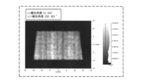
- FIGS. 8 to 11 illustrate simulation results conducted by the inventor of the present invention regarding brightness unevenness caused by the polarization state of the propagating light L11 described above.
- FIG. 8 shows an example of simulation results when the polarization state of the propagating light L11 is unstable.
- FIG. 9 shows an example of simulation results when the polarization state of the propagating light L11 is stable.
- FIG. 10 shows another example of the simulation results when the polarization state of the propagating light L11 is unstable.
- FIG. 11 shows another example of the simulation results when the polarization state of the propagating light L11 is stable.
- FIG. 8 a case is illustrated in which the image light L1 incident on the coupling region 21 has a polarization angle of "90.00°" with respect to S-polarized light, that is, it is S-polarized light.
- the initial polarization angle of the propagating light L11 in the first expansion region 23 was "20.83°". For this reason, the polarization state of the propagating light L11 deviates from the S-polarized light, etc., and as shown in FIG. 8, brightness unevenness was observed in the brightness distribution in the X direction corresponding to the horizontal direction of the virtual image Iv.
- the polarization angle of the image light L1 is set to "30.00°".
- the initial polarization angle of the propagating light L11 was "3.30°”
- the polarization state of the propagating light L11 was set to be near S polarization.
- FIG. 10 shows an example in which the polarization angle of the image light L1 incident on the coupling region 21 is "60.00°", and the polarization angle of the initial propagation light L11 is "42.04°".
- the polarization state of the propagating light L11 was significantly different from both the P-polarized light and the S-polarized light, uneven brightness was observed in the brightness distribution after the pupil dilation, as shown in FIG. For example, a change in brightness was observed for about three cycles in the X direction.
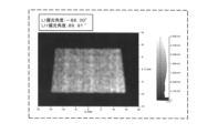
- the polarization angle of the image light L1 is set to "-88.00°".
- the initial polarization angle of the propagating light L11 was "89.91°”
- the polarization state of the propagating light L11 was set to be near P polarization.
- FIG. 12 illustrates the relationship between the diffraction pitch Gp2 and the diffraction efficiency in the first expansion region 23.
- FIG. 12 was obtained as a result of a numerical simulation of the diffraction efficiency when the polarization state of the propagating light L11 was changed in a state where various diffraction pitches Gp2 were set in the first expansion region 23.
- the wavelength ⁇ of the propagating light L11 is set to "0.52 ⁇ m”
- the thickness d between the main surfaces 13a and 13b of the light guide 13 is set to "5 ⁇ m”
- the refractive index n of the hologram material was set to "1.505”
- the refractive index modulation amount ⁇ n of the hologram was set to "0.02”.
- the relationship between the incident angle and the output angle at the diffraction position P1 of the first expansion region 23 is that in a diffraction structure in which the traveling direction of the incident light is the X direction and the output light is propagated in the Y direction, the incident angle and the output angle are the same.
- the size was set to change according to the diffraction pitch Gp2.
- the horizontal axis is the diffraction pitch [ ⁇ m]
- the vertical axis is the diffraction efficiency [%].
- Graph E1 shows the maximum value of diffraction efficiency in propagating light L11 whose polarization state has been changed.
- Graph E2 shows the minimum value of the diffraction efficiency in the propagating light L11 whose polarization state has been changed.
- the first expansion region 23 of this embodiment from the viewpoint of obtaining a relatively large diffraction power from the propagating light L11 propagating in the X direction to the divided light L12 propagating in the Y direction, the first expansion region 23 is 1.0 ⁇ /n [ ⁇ m ] It is possible to use the following diffraction pitch Gp2. Then, in the example of FIG. 12, a large discrepancy of 30% or more in diffraction efficiency occurs between the graph E1 of the maximum value of the diffraction efficiency and the graph E2 of the minimum value when the polarization state of the propagating light L11 changes. ing. Further, as the diffraction pitch Gp2 becomes narrower, the deviation in diffraction efficiency becomes larger.
- the polarization state of the propagating light L11 in the first expansion region 23 is unstable, there is a concern that brightness unevenness may occur.
- the polarization state of the propagating light L11 in the first extension region 23 is stabilized, so the diffraction pitch is narrow such as 1.0 ⁇ /n [ ⁇ m] or less. Even if Gp2 is used, brightness unevenness can be reduced. Further, in the first expansion region 23, it is also possible to easily obtain larger diffraction power by using a narrower diffraction pitch Gp2.
- the divided light L12 propagating in the Y direction within the light guide 13 is diffracted into duplicate light L13 that is emitted to the outside of the light guide 13 while being tilted in the Y direction.
- a relatively small degree of diffraction power is sufficient. Therefore, in the second expansion region 25 of this embodiment, a diffraction pitch Gp3 wider than the diffraction pitch Gp2 of the first expansion region 23 can be used.
- FIG. 13 illustrates the relationship between the diffraction pitch Gp3 and the diffraction efficiency in the second expansion region 23.
- the same numerical simulation as in FIG. 12 was performed for the second expansion region 25.
- the wavelength ⁇ of the split light L12, the thickness d of the light guide 13, and the refractive index n of the hologram material are set in the same way as in the case of FIG. 12, and the refractive index modulation amount ⁇ n of the hologram is 0. It was set to 03. Further, the incident angle at the diffraction position P2 of the second expansion region 25 is set to 45°, and the output angle is smaller than the critical angle of the light guide 13 and changes according to the diffraction pitch Gp3 in the output range. It was set to Graph F1 shows the maximum value of diffraction efficiency in divided light L12 whose polarization state has been changed. Graph F2 shows the minimum value of the diffraction efficiency in the divided light L12 whose polarization state has been changed.
- the diffraction pitch Gp3 of the second expansion region 25 is in the range of 1.23 ⁇ /n [ ⁇ m] or more and 10.0 ⁇ /n [ ⁇ m] or less. It was confirmed that it can be set within R1.
- the graph F1 of the maximum value of the diffraction efficiency of the split light L12 has a minimum value, so that when it falls below the lower limit value, it is due to a change in the polarization state. Fluctuations in diffraction efficiency become noticeable.
- the diffraction pitch Gp3 of the second expansion region 25 exceeds the lower limit value of the range R1, fluctuations in the diffraction efficiency due to changes in the polarization state of the divided light L12 in the second expansion region 25 can be reduced, and the virtual image Deterioration in IV image quality can be suppressed.
- the wider the diffraction pitch Gp3 the smaller the difference between the graph F1 of the maximum value and the graph F2 of the minimum value of the diffraction efficiency of the split light L12.
- the diffraction pitch Gp3 is 2.4 ⁇ m or less, it is advantageous in that fluctuations in diffraction efficiency due to changes in polarization state can be reduced to less than 1%.
- each of the graphs F1 and F2 of the diffraction efficiency of the divided light L12 has a range R2 in which the diffraction pitch Gp3 reaches its peak value in the vicinity of 1.4 ⁇ m to 2.0 ⁇ m. That is, when the diffraction pitch Gp3 is widened beyond the peak range R2, the diffraction efficiency decreases regardless of the polarization state. On the other hand, when the diffraction pitch Gp3 of the second expansion region 25 is less than the upper limit of the range R1, the diffraction efficiency of the divided light L12 can be ensured to be more than half of the peak value.
- the image display device 2 in this embodiment allows the virtual image Iv to be viewed as an example of an optical image, and includes the display section 11 and the light guide 13.
- the display unit 11 emits image light L1 that is visually recognized as a virtual image Iv.
- the light guide 13 guides the image light L1 from the display section 11 to the outside.
- the light guide 13 has a pair of principal surfaces 13a and 13b facing each other.
- the light guide 13 is provided with a coupling region 21, which is an example of an incident region, and first and second extension regions 23, which are each an example of an extension region.
- the image light L1 from the display section 11 is incident, and the image light L1 is diffracted so as to propagate inside the light guide 13 by reflection between the pair of main surfaces 13a and 13b.
- the first expansion region 23 diffracts the propagated image light L11 at a plurality of positions P1 where the image light propagates in the light guide 13, and outputs the diffracted image light L11 as a plurality of image lights.
- the image light L11 propagated to the first expansion area 23 is located on a plane (XZ plane) including the normal direction (Z direction) of the main surfaces 13a and 13b in the first expansion area 23 and the propagation direction (X direction) of the propagated light L11.
- the image light L1 incident on the coupling region 21 is polarized in the first polarization state so that it is near P polarization or near S polarization, as an example of the first polarization state polarized along the direction parallel or perpendicular to ). (See FIGS. 5(A) and 5(B)).
- the polarization state of the propagating light L11 in the first extension region 23 can be stabilized, fluctuations in diffraction efficiency can be reduced, and brightness unevenness can be reduced. In this way, fluctuations in image quality in the image display device 2 that makes the virtual image Iv visible can be suppressed.
- the propagation direction of the propagation light L11 is defined, for example, by the direction of a light ray such as a central ray in the luminous flux of the propagation light L11. Further, the first polarization state may be specified from each of the principal planes 13a and 13b orthogonal to the above plane.
- the image light L1 enters the coupling region 21 at an angle oblique to the normal direction (Z direction) of the main surfaces 13a and 13b and propagates inside the light guide 13.
- a bonding region 21 is provided so as to do so.
- the polarization state of the image light L1 that enters the coupling region 21 is set so that the image light L11 in the first expansion region 23 has a specific polarization state. Therefore, fluctuations in image quality in the image display device 2 can be suppressed.
- the inclination at which the image light L1 enters the coupling region 21 is between the first direction (X direction) in which the plurality of positions P1 are lined up in the first expansion region 23 and the main surfaces 13a and 13b. It is inclined in a second direction (Y direction) that intersects with a plane including the normal direction (Z direction).
- the plane of incidence of the image light L1 in the coupling region 21 is different from the plane of incidence of the propagating light L11 in the first extension region 23 (see FIG. 4).
- Luminance unevenness in the image display device 2 can be reduced by taking into consideration the shift in the polarization state of the propagating light L11 from the polarization state of the image light L1 due to such a difference in the incident plane.
- the extension region includes first and second extension regions 23 and 25 having diffraction pitches Gp2 and Gp3 that are different from each other.
- the diffraction pitch Gp2 of the first expansion region 23 is narrower than the diffraction pitch Gp3 of the second expansion region 25.
- the image light L1 that enters the coupling region 21 is set to the second polarization state so that the image light L11 propagated to the first extension region 23 becomes the first polarization state.
- the first extension region 23 is configured to guide light so as to diffract the image light L11 propagated from the coupling region 21 and output a plurality of image lights L12 to the second extension region 25. It is provided in the body 13. By stabilizing the polarization state in the first extension region 23 near the combination region 21 among the plurality of extension regions 23 and 25, fluctuations in the image quality of the virtual image Iv due to brightness unevenness can be easily suppressed.
- the diffraction pitch Gp3 in the second expansion region 25 is 1.23 ⁇ /n or more using the wavelength ⁇ of the image light L1 and the refractive index n in the light guide 13. Moreover, it is 10.0 ⁇ /n or less. According to such a relatively wide diffraction pitch Gp3, even if the polarization state in the second extension region 25 is unstable, fluctuations in diffraction efficiency can be suppressed, and the image quality in the image display device 2 can be improved.
- the first polarization state includes at least one of P-polarized light and S-polarized light.
- the first polarization state does not have to be exactly the same as the P-polarized light and the S-polarized light, and can be appropriately set within an acceptable error range. By using such a first polarization state, fluctuations in image quality in the image display device 2 can be suppressed.
- the second polarization state has a polarization angle ⁇ that is obtained by rotating the polarization direction from P polarization or S polarization.
- the second polarization state is a polarization state different from P-polarization and S-polarization.
- the second polarization state is linearly polarized light that is different from P and S polarized light.
- the second polarization state can also be set as appropriate within the tolerance range. By setting such a second polarization state, fluctuations in image quality in the image display device 2 can be suppressed.
- the second polarization state may be circularly polarized light or elliptically polarized light.
- the image display device 2 may further include a polarization setting section 14.
- the polarization setting section 14 is disposed between the display section 11 and the light guide 13, and sets the image light L1 entering the coupling region 21 from the display section 11 to a second polarization state. By setting the second polarization state by the polarization setting unit 14, fluctuations in image quality in the image display device 2 can be suppressed.
- the polarization setting unit 14 includes, for example, at least one of a half-wave plate, a quarter-wave plate, and a polarizing plate.
- the display section 11 may be arranged so that the display section 11 emits image light to the light guide 13 in the second polarization state. Even with this arrangement of the display section 11, fluctuations in image quality in the image display device 2 can be suppressed by setting the second polarization state.
- the light guide 13 is arranged so as to guide the image light from the display section 11 to the light-transmitting member.
- the image display device 2 constitutes a head-up display that displays a virtual image Iv in the HUD system 1 through a transparent member such as a windshield 5.
- the image display device 2 of this embodiment can suppress fluctuations in the image quality of the virtual image Iv in the HUD system 1.
- the optical system 20 of this embodiment includes a light guide 13 and a polarization setting section 14.
- the light guide 13 guides the image light L1 from the display unit 11, which emits the image light L1 visually recognized as the virtual image Iv, to the outside.
- the polarization setting section 14 is arranged between the display section 11 and the light guide 13.
- the light guide 13 has a pair of main surfaces 13a and 13b facing each other.
- the light guide 13 includes an incident area for diffracting the image light and a light guide so that the image light from the display section 11 enters and propagates inside the light guide 13 by reflection between a pair of main surfaces.
- extension regions are provided that diffract the propagated image light and emit the image light as a plurality of image lights.
- the polarization setting unit 14 is configured to polarize the image light propagated to the expansion area along a direction parallel or perpendicular to a plane including the normal direction of the main surface in the expansion area and the propagation direction of the propagated image light.
- the image light incident on the incident region is set to a second polarization state different from the first polarization state so that the image light is in the first polarization state.
- Embodiment 1 has been described as an example of the technology disclosed in this application.
- the technology in the present disclosure is not limited to this, and can also be applied to embodiments in which changes, substitutions, additions, omissions, etc. are made as appropriate.
- Embodiment 1 described above describes a configuration example in which the first extension region 23 is arranged on the +X side of the coupling region 21 in the light guide 13, and the second extension region 25 is arranged on the +Y side of the first extension region 23. did.
- the arrangement of the regions 21, 23, and 25 is not limited to the above configuration example.
- the first extension region 23 is arranged on the +Y side of the coupling region 21, and the first extension region 23
- the second expansion region 25 may be arranged on the +X side of the second expansion region 25 .
- polarization control is performed to stabilize the polarization state of the image light propagating toward the narrower diffraction pitch of the two extended regions 23 and 25 arranged as described above. May be done.
- the number of expansion regions provided in the light guide 13 is not limited to two, but may be one, or three or more.
- the image display device in which the image light L1 incident on the light guide 13 and the image light L2 emitted from the light guide 13 are tilted in the Y direction with respect to the normal line of the light guide 13. 2 was explained.
- the image lights L1 and L2 do not need to be tilted as described above, and may be tilted in a direction different from the Y direction, for example. Further, one or both of the image lights L1 and L2 may be parallel to the normal line of the light guide 13.
- the HUD system 1 applied to the vehicle 3 has been described, but the object to which the HUD system 1 is applied is not limited to the vehicle 3 in this embodiment.
- the object of the HUD system 1 in this embodiment may be various types of moving objects such as trains, motorcycles, ships, and airplanes, or may be an amusement machine or the like without a moving object.
- the image display device 2 of this embodiment may be arranged so as to emit the image light L2 to a transparent member provided on various objects in the HUD system 1.
- the image display device 2 and the optical system 20 that make the virtual image Iv visible as an example of an optical image have been described.
- the optical image displayed by the image display device 2 is not limited to the virtual image Iv, but may be a real image, for example.
- the image display device 2 of the present embodiment is configured such that a real image is formed between a transparent member such as the windshield 5 and the viewer D using the pupil expansion type optical system 20 similar to that described above. may be done. Displaying such a real image is useful, for example, in amusement applications.
- the image display device 2 included in the HUD system 1 has been described, but the image display device 2 does not need to be included in the HUD system 1 in this embodiment.
- the image display device 2 may be any of various image display devices that display an optical image such as a virtual image or a real image such as an HMD or an electronic mirror.
- a first aspect of the present disclosure is an image display device for visually recognizing an optical image, which includes a display section that emits image light that is visually recognized as an optical image, and a guide that guides the image light from the display section to the outside.
- a light body is provided.
- the light guide has a pair of main surfaces facing each other. In the light guide, the image light from the display section is incident and propagated inside the light guide by reflection between a pair of main surfaces. At a plurality of positions where the light propagates, extension regions are provided that diffract the propagated image light and emit the image light as a plurality of image lights.
- the image light propagated to the expansion area becomes a first polarization state in which it is polarized along a direction parallel or perpendicular to a plane including the normal direction of the main surface in the expansion area and the propagation direction of the propagated image light.
- the image light incident on the incident region is set to a second polarization state different from the first polarization state.
- the image light is incident at an angle oblique to the normal direction of the principal surface in the incident region and propagates inside the light guide.
- An entrance region is provided.
- the inclination at which the image light is incident in the incident area is a plane that includes a first direction in which the plurality of positions are lined up in the extended area and a normal direction of the main surface. is tilted in a second direction intersecting with .
- the extension region includes first and second extension regions having different diffraction pitches.
- the diffraction pitch of the first extension region is narrower than the diffraction pitch of the second extension region.
- the image light incident on the incident region is set to the second polarization state so that the image light propagated to the first expansion region is in the first polarization state.
- the first extension region diffracts the image light propagated from the incident region and guides the plurality of image lights to the second extension region. Provided on the light body.
- the diffraction pitch in the second extension region is 1.23 ⁇ using the wavelength ⁇ of the image light and the refractive index n in the light guide. It is not less than ⁇ /n and not more than 10.0 ⁇ /n.
- the first polarization state includes one of P-polarized light and S-polarized light.
- the second polarization state includes P-polarized light and S-polarized light having a polarization angle obtained by rotating the polarization direction from P-polarized light or S-polarized light. It is a different polarized light.
- the image display device is disposed between a display section and a light guide, and transmits image light incident from the display section to the incident area. It further includes a polarization setting section that sets the polarization state.
- the polarization setting section includes at least one of a half-wave plate, a quarter-wave plate, and a polarizing plate.
- the display section is arranged so that the display section emits image light to the light guide in the second polarization state.
- the light guide is arranged to guide image light from the display section to the light-transmitting member, and A head-up display that displays a virtual image is constructed using
- a thirteenth aspect includes a light guide that guides image light from a display section that emits image light that is visually recognized as an optical image to the outside, and a polarization setting section that is disposed between the display section and the light guide. It is an optical system equipped with.
- the light guide has a pair of main surfaces facing each other. In the light guide, the image light from the display section is incident and propagated inside the light guide by reflection between a pair of main surfaces. At a plurality of positions where the light propagates, extension regions are provided that diffract the propagated image light and emit the image light as a plurality of image lights.
- the polarization setting unit includes a first polarization unit in which the image light propagated to the expansion area is polarized along a direction parallel or perpendicular to a plane including the normal direction of the main surface in the expansion area and the propagation direction of the propagated image light.
- the image light incident on the incident region is set to a second polarization state different from the first polarization state so that the image light has a polarization state of .
- the optical system of the thirteenth aspect has the characteristics of any one of the second to tenth aspects.
- the present disclosure is applicable to an image display device that allows an observer to visually recognize an optical image, and is applicable to, for example, a HUD, an HMD, an electronic mirror, and the like.
Abstract
An image display device (2) for enabling an optical image to be visually recognized comprises: a display unit that emits image light to be visually recognized as a virtual image; and a light guide body (13) that guides the image light from the display unit to the outside. The light guide body has a pair of opposite main surfaces (13a, 13b). The light guide body is provided with: an entry region (21) in which the image light from the display unit enters and the image light is diffracted so as to be propagated inside the light guide body as a result of reflection between the pair of main surfaces; and an extension region (23) in which the propagated image light is diffracted at a plurality of positions of the light guide body through which the image light propagates, and is emitted as a plurality of rays of image light. In order for the image light propagating in the extension region to be set in a first polarized state in which the image light is polarized in a direction parallel to or perpendicular to a surface, in extension region, including the normal direction of the main surfaces and the propagation direction of the propagated image light, the image light that entered in the entry region is set in a second polarized state different from the first polarized state.
Description
本開示は、観察者に虚像等の光学像を視認させる画像表示装置、及び画像表示装置に用いられる光学系に関する。
The present disclosure relates to an image display device that allows an observer to view an optical image such as a virtual image, and an optical system used in the image display device.
特許文献1は、仮想現実または複合現実のヘッドマウントディスプレイ(HMD)装置等において、瞳拡張のための複数の回折光学素子(DOE)を備えた光学表示システムを開示する。この光学表示システムでは、イメージャからの主ビームが、TM偏光ビーム又はTE偏光ビーム等として、第1のDOEから第2のDOEに伝搬する。第2のDOEは、光学ビームの瞳拡張を行うことに加えて、光摂動の偏光の状態を回転するように構成された格子特徴を含む。こうした第2のDOEにおいて、摂動ビームの偏光を、画像表示に用いられる主ビームの偏光に対して直交するように回転することにより、光の干渉が低減されている。
Patent Document 1 discloses an optical display system including a plurality of diffractive optical elements (DOE) for pupil dilation in a virtual reality or mixed reality head mounted display (HMD) device or the like. In this optical display system, a main beam from an imager propagates from a first DOE to a second DOE, such as as a TM polarized beam or a TE polarized beam. In addition to providing pupil dilation of the optical beam, the second DOE includes grating features configured to rotate the state of polarization of the optical perturbation. In such a second DOE, light interference is reduced by rotating the polarization of the perturbation beam to be orthogonal to the polarization of the main beam used for image display.
本開示は、虚像を視認させる画像表示装置における画質の変動を抑制することができる画像表示装置及び光学系を提供する。
The present disclosure provides an image display device and an optical system that can suppress fluctuations in image quality in an image display device that makes a virtual image visible.
本開示における画像表示装置は、光学像を視認させる画像表示装置であって、光学像として視認される画像光を出射する表示部と、表示部からの画像光を外部に導光する導光体とを備える。導光体は、互いに対向する一対の主面を有する。導光体において、表示部からの画像光が入射して、一対の主面の間の反射によって導光体の内部を伝搬するように、画像光を回折する入射領域と、導光体において画像光が伝搬する複数の位置において、伝搬した画像光を回折して、複数の画像光として出射する拡張領域とが設けられる。拡張領域に伝搬した画像光が、拡張領域における主面の法線方向と伝搬した画像光の伝搬方向とを含む面に対して平行又は垂直な方向に沿って偏光した第1の偏光状態となるように、入射領域に入射する画像光が、第1の偏光状態とは異なる第2の偏光状態に設定される。
An image display device in the present disclosure is an image display device that allows an optical image to be viewed, and includes a display unit that emits image light that is viewed as an optical image, and a light guide that guides the image light from the display unit to the outside. Equipped with. The light guide has a pair of principal surfaces facing each other. In the light guide, the image light from the display section is incident and propagated inside the light guide by reflection between a pair of main surfaces. At a plurality of positions where the light propagates, extension regions are provided that diffract the propagated image light and emit the image light as a plurality of image lights. The image light propagated to the expansion area becomes a first polarization state in which it is polarized along a direction parallel or perpendicular to a plane including the normal direction of the main surface in the expansion area and the propagation direction of the propagated image light. Thus, the image light incident on the incident region is set to a second polarization state different from the first polarization state.
本開示における光学系は、光学像として視認される画像光を出射する表示部からの画像光を外部に導光する導光体と、表示部と導光体との間に配置される偏光設定部とを備える。導光体は、互いに対向する一対の主面を有する。導光体において、表示部からの画像光が入射して、一対の主面の間の反射によって導光体の内部を伝搬するように、画像光を回折する入射領域と、導光体において画像光が伝搬する複数の位置において、伝搬した画像光を回折して、複数の画像光として出射する拡張領域とが設けられる。偏光設定部は、拡張領域に伝搬した画像光が、拡張領域における主面の法線方向と伝搬した画像光の伝搬方向とを含む面に対して平行又は垂直な方向に沿って偏光した第1の偏光状態となるように、入射領域に入射する画像光を、第1の偏光状態とは異なる第2の偏光状態に設定する。
The optical system in the present disclosure includes a light guide that guides image light from a display section that emits image light that is visually recognized as an optical image to the outside, and a polarization setting that is arranged between the display section and the light guide. It is equipped with a section. The light guide has a pair of main surfaces facing each other. In the light guide, the image light from the display section is incident and propagated inside the light guide by reflection between a pair of main surfaces. At a plurality of positions where the light propagates, extension regions are provided that diffract the propagated image light and emit the image light as a plurality of image lights. The polarization setting unit includes a first polarization unit in which the image light propagated to the expansion area is polarized along a direction parallel or perpendicular to a plane including the normal direction of the main surface in the expansion area and the propagation direction of the propagated image light. The image light incident on the incident region is set to a second polarization state different from the first polarization state so that the image light has a polarization state of .
本開示における画像表示装置及び光学系によると、虚像を視認させる画像表示装置における画質の変動を抑制することができる。
According to the image display device and optical system of the present disclosure, it is possible to suppress fluctuations in image quality in the image display device that makes a virtual image visible.
以下、適宜図面を参照しながら、実施の形態を詳細に説明する。但し、必要以上に詳細な説明は省略する場合がある。例えば、既によく知られた事項の詳細説明や実質的に同一の構成に対する重複説明を省略する場合がある。これは、以下の説明が不必要に冗長になるのを避け、当業者の理解を容易にするためである。
Hereinafter, embodiments will be described in detail with reference to the drawings as appropriate. However, more detailed explanation than necessary may be omitted. For example, detailed explanations of well-known matters or redundant explanations of substantially the same configurations may be omitted. This is to avoid unnecessary redundancy in the following description and to facilitate understanding by those skilled in the art.
なお、出願人は、当業者が本開示を十分に理解するために添付図面および以下の説明を提供するのであって、これらによって特許請求の範囲に記載の主題を限定することを意図するものではない。
The applicant provides the accompanying drawings and the following description to enable those skilled in the art to fully understand the present disclosure, and they are not intended to limit the subject matter recited in the claims. do not have.
(実施形態1)
以下、本開示の実施形態1について、図面を参照しながら説明する。本実施形態では、瞳拡張型の画像表示装置および光学系を適用するシステムの一例について説明する。 (Embodiment 1)
Embodiment 1 of the present disclosure will be described below with reference to the drawings. In this embodiment, an example of a system to which a pupil expansion type image display device and optical system are applied will be described.
以下、本開示の実施形態1について、図面を参照しながら説明する。本実施形態では、瞳拡張型の画像表示装置および光学系を適用するシステムの一例について説明する。 (Embodiment 1)
1.構成
1-1.システム概要
図1は、本実施形態に係るヘッドアップディスプレイ(HUD)システム1の概要を説明するための図である。HUDシステム1は、例えば図1に示すように、画像表示装置2と、ウインドシールド5とを含む。HUDシステム1は、例えばウインドシールド5が設けられる車両3等において、搭乗者等の観察者Dに虚像Ivを光学像の一例として視認させるシステムである。HUDシステム1において、観察者Dの眼が位置することにより虚像Ivが観察者Dに視認可能となる領域を、視認領域Acという。 1. Configuration 1-1. System Overview FIG. 1 is a diagram for explaining an overview of a head-up display (HUD)system 1 according to the present embodiment. The HUD system 1 includes, for example, as shown in FIG. 1, an image display device 2 and a windshield 5. The HUD system 1 is a system that allows an observer D such as a passenger to visually recognize a virtual image Iv as an example of an optical image, for example in a vehicle 3 or the like in which a windshield 5 is provided. In the HUD system 1, the area where the observer D's eyes are positioned so that the virtual image Iv becomes visible to the observer D is referred to as a visibility area Ac.
1-1.システム概要
図1は、本実施形態に係るヘッドアップディスプレイ(HUD)システム1の概要を説明するための図である。HUDシステム1は、例えば図1に示すように、画像表示装置2と、ウインドシールド5とを含む。HUDシステム1は、例えばウインドシールド5が設けられる車両3等において、搭乗者等の観察者Dに虚像Ivを光学像の一例として視認させるシステムである。HUDシステム1において、観察者Dの眼が位置することにより虚像Ivが観察者Dに視認可能となる領域を、視認領域Acという。 1. Configuration 1-1. System Overview FIG. 1 is a diagram for explaining an overview of a head-up display (HUD)
本実施形態の画像表示装置2は、例えば図1に示すように、虚像Ivとして視認させる画像光L1を生成する表示部11と、表示部11からの画像光L1の瞳(例えば射出瞳)を拡張して、拡張された画像光L2をウインドシールド5に導光する導光体13とを備える。こうした瞳拡張型の画像表示装置2によると、HUDシステム1における視認領域Acを大きく確保し易い。
For example, as shown in FIG. 1, the image display device 2 of this embodiment includes a display unit 11 that generates image light L1 that is visually recognized as a virtual image Iv, and a pupil (for example, an exit pupil) of the image light L1 from the display unit 11. The light guide 13 is expanded to guide the expanded image light L2 to the windshield 5. According to such a pupil expansion type image display device 2, it is easy to ensure a large viewing area Ac in the HUD system 1.
瞳拡張技術をHUDに適用した場合、例えば観察者Dが眼を視認領域Ac内で動かした際に虚像Ivの明るさが変化するといった輝度ムラが顕著で、画質が変動する課題が考えられる。そこで、本実施形態では、こうした輝度ムラの課題を解決して画質の変動を抑制するべく、瞳拡張型の画像表示装置2における偏光を制御する構成を採用する。以下本実施形態のHUDシステム1における画像表示装置2の構成について説明する。
When the pupil dilation technology is applied to a HUD, there may be a problem that, for example, the brightness of the virtual image Iv changes when the observer D moves his or her eyes within the viewing area Ac, resulting in noticeable brightness unevenness and fluctuations in image quality. Therefore, in this embodiment, in order to solve the problem of such brightness unevenness and suppress fluctuations in image quality, a configuration is adopted in which polarization in the pupil expansion type image display device 2 is controlled. The configuration of the image display device 2 in the HUD system 1 of this embodiment will be described below.
1-2.システム構成
図2は、本実施形態に係るHUDシステム1の構成を例示する。HUDシステム1において、画像表示装置2は、例えば車両3におけるウインドシールド5の下方においてダッシュボード(図示省略)の内部等に配置される。本実施形態の画像表示装置2は、例えば図2に示すように、表示部11と、導光体13と、偏光設定部14と、制御部15とを備える。導光体13と偏光設定部14とで構成される光学系20は、本実施形態の画像表示装置2における光学系の一例である。 1-2. System Configuration FIG. 2 illustrates the configuration of theHUD system 1 according to this embodiment. In the HUD system 1, the image display device 2 is arranged, for example, inside a dashboard (not shown) below the windshield 5 of the vehicle 3. The image display device 2 of this embodiment includes a display section 11, a light guide 13, a polarization setting section 14, and a control section 15, as shown in FIG. 2, for example. The optical system 20 composed of the light guide 13 and the polarization setting section 14 is an example of an optical system in the image display device 2 of this embodiment.
図2は、本実施形態に係るHUDシステム1の構成を例示する。HUDシステム1において、画像表示装置2は、例えば車両3におけるウインドシールド5の下方においてダッシュボード(図示省略)の内部等に配置される。本実施形態の画像表示装置2は、例えば図2に示すように、表示部11と、導光体13と、偏光設定部14と、制御部15とを備える。導光体13と偏光設定部14とで構成される光学系20は、本実施形態の画像表示装置2における光学系の一例である。 1-2. System Configuration FIG. 2 illustrates the configuration of the
ウインドシールド5は、車両3等の移動体に設けられる透光部材の一例である。HUDシステム1の透光部材は、ウインドシールド5に限らず、例えばコンバイナなど、可視光領域において透光性を有する各種の部材であってもよい。
The windshield 5 is an example of a light-transmitting member provided on a moving object such as the vehicle 3. The light-transmitting member of the HUD system 1 is not limited to the windshield 5, and may be any of various members having light-transmitting properties in the visible light region, such as a combiner.
表示部11は、例えば複数画素で画像を表示する表示面を有し、表示面における画像を示す画像光L1を生成する表示素子である。例えば、表示部11は、液晶ディスプレイ、有機発光ダイオード(Organic Light-Emitting Diode)ディスプレイ、LCOS(Liquid Crystal On Silicon)、DMD(Digital Mirror Device)、マイクロLED、又は走査型MEMSミラーを含む。
The display unit 11 is a display element that has a display surface that displays an image using, for example, a plurality of pixels, and that generates image light L1 that represents the image on the display surface. For example, the display unit 11 includes a liquid crystal display, an organic light-emitting diode (organic light-emitting diode) display, an LCOS (liquid crystal on silicon), a DMD (digital mirror device), a micro LED, or a scanning MEMS mirror.
表示部11は、内部に表示面を有さなくてもよい。表示部11の外部にスクリーン等の表示面が設けられてもよい。表示部11は、画像光L1を生成するための単色又は複数色を発光するレーザ光源又はLED光源などの各種光源を含んでもよい。画像光L1は、例えば画像の画角に対応する発散角の光束で構成される。こうした各種の光束について、図中では適宜、中心光線などの光線光路を図示する。
The display unit 11 does not need to have a display surface inside. A display surface such as a screen may be provided outside the display unit 11. The display unit 11 may include various light sources such as a laser light source or an LED light source that emit light in a single color or multiple colors to generate the image light L1. The image light L1 is composed of a light beam having a divergence angle corresponding to the angle of view of the image, for example. Regarding these various types of light beams, the optical paths of light rays such as the central ray are illustrated as appropriate in the drawings.
導光体13は、可視光領域において透明な材料により形成され、入射した光が内部で全反射可能に構成される導光部材である。導光体13は、互いに対向する一対の主面13a,13bを有する。導光体13は、平面形状に限らず曲面形状であってもよい。以下では、第1主面13aと第2主面13bとが平行な平面形状である導光体13の構成例を説明する。図2では1つの導光体13を図示しているが、画像表示装置2は複数の導光体13を備えてもよい。例えば、RGBの色別の導光体13が用いられてもよい。
The light guide 13 is a light guide member that is formed of a material that is transparent in the visible light region and is configured to allow total internal reflection of incident light. The light guide 13 has a pair of principal surfaces 13a and 13b facing each other. The light guide 13 is not limited to a planar shape, but may have a curved shape. Below, a configuration example of the light guide 13 having a planar shape in which the first main surface 13a and the second main surface 13b are parallel will be described. Although one light guide 13 is illustrated in FIG. 2, the image display device 2 may include a plurality of light guides 13. For example, light guides 13 for different colors of RGB may be used.
導光体13は、例えば、各主面13a,13bといった表面が鏡面加工されたガラス又は樹脂製の板で構成される。以下、導光体13の主面13a,13bの法線方向をZ方向とし、主面13a,13bに平行で互いに直交する2方向をX,Y方向とする。X方向は虚像Ivの水平方向に対応し、Y方向は虚像Ivの垂直方向に対応する。
The light guide 13 is composed of, for example, a glass or resin plate whose main surfaces 13a and 13b are mirror-finished. Hereinafter, the normal direction of the main surfaces 13a and 13b of the light guide 13 will be referred to as the Z direction, and the two directions parallel to the main surfaces 13a and 13b and orthogonal to each other will be referred to as the X and Y directions. The X direction corresponds to the horizontal direction of the virtual image Iv, and the Y direction corresponds to the vertical direction of the virtual image Iv.
導光体13は、例えば車両3において下方に-Z側の第1主面13aを向けて上方に+Z側の第2主面13bを向けた状態で配置される。導光体13は、例えば各種の配置制約にしたがって、図2に示すように車両3において傾けて配置される。導光体13の配置制約は、例えば車両3外部から太陽光等がウインドシールド5を介して導光体13に入射した際の反射光が、視認領域Acに到らないようにすること等である。
The light guide 13 is arranged in the vehicle 3, for example, with the first principal surface 13a on the -Z side facing downward and the second principal surface 13b on the +Z side facing upward. The light guide 13 is arranged at an angle in the vehicle 3 as shown in FIG. 2, for example, according to various arrangement restrictions. The arrangement constraints of the light guide 13 are, for example, to prevent reflected light when sunlight or the like from outside the vehicle 3 enters the light guide 13 through the windshield 5 from reaching the visibility area Ac. be.
本実施形態の画像表示装置2において、導光体13は、-Z側の表示部11から入射する画像光L1と、+Z側のウインドシールド5に出射する画像光L2とが、各主面13a,13bの法線に対してそれぞれY方向に傾くように構成される。本実施形態の画像表示装置2において、導光体13には、瞳拡張の動作を実現するための回折構造が設けられる。導光体13の構成の詳細は後述する。
In the image display device 2 of the present embodiment, the light guide 13 allows the image light L1 incident from the display section 11 on the -Z side and the image light L2 emitted to the windshield 5 on the +Z side to be directed to each main surface 13a. , 13b, respectively, so as to be inclined in the Y direction. In the image display device 2 of this embodiment, the light guide 13 is provided with a diffraction structure for realizing the pupil dilation operation. Details of the configuration of the light guide 13 will be described later.
偏光設定部14は、例えば表示部11と導光体13との間に配置された種々の光学素子で構成され、表示部11から導光体13に入射する画像光L1を特定の偏光状態に設定する。例えば、偏光設定部14は、半波長板、1/4波長板、および偏光板のうちの1つ又は複数の光学素子を含む。偏光設定部14は、表示部11と導光体13との間に設けられるコリメータなどの各種光学系に組み込まれてもよいし、表示部11又は導光体13と一体的に構成されてもよい。
The polarization setting unit 14 is composed of various optical elements disposed between the display unit 11 and the light guide 13, for example, and sets the image light L1 entering the light guide 13 from the display unit 11 into a specific polarization state. Set. For example, the polarization setting unit 14 includes one or more optical elements of a half-wave plate, a quarter-wave plate, and a polarizing plate. The polarization setting section 14 may be incorporated into various optical systems such as a collimator provided between the display section 11 and the light guide 13, or may be configured integrally with the display section 11 or the light guide 13. good.
画像表示装置2は、偏光設定部14としての光学素子を備えなくてもよい。例えば、表示部11がレーザ光源等により直線偏光などの所定の偏光状態で画像光L1を生成する場合、偏光設定部14の機能は、画像光L1の光軸方向における回転などの表示部11と導光体13との位置合わせにより実現されてもよい。
The image display device 2 does not need to include an optical element as the polarization setting section 14. For example, when the display unit 11 generates the image light L1 in a predetermined polarization state such as linearly polarized light using a laser light source or the like, the function of the polarization setting unit 14 is to rotate the image light L1 in the optical axis direction. This may be realized by alignment with the light guide 13.
制御部15は、例えば画像表示装置2の動作全体を制御する。制御部15は、半導体素子などで構成される回路で実現可能である。制御部15は、例えば、マイコン、CPU、MPU、GPU、DSP、FPGA、またはASICで構成することができる。制御部15は、内部メモリ等に格納されたデータやプログラムを読み出して種々の演算処理を行うことで、予め定められた機能を実現する。また、制御部15は、内部メモリ等の記憶装置17を備える。制御部15は、画像表示装置2の外部構成であってもよい。
The control unit 15 controls the entire operation of the image display device 2, for example. The control unit 15 can be realized by a circuit made up of semiconductor elements or the like. The control unit 15 can be configured with, for example, a microcomputer, CPU, MPU, GPU, DSP, FPGA, or ASIC. The control unit 15 realizes predetermined functions by reading data and programs stored in an internal memory or the like and performing various arithmetic operations. The control unit 15 also includes a storage device 17 such as an internal memory. The control unit 15 may be an external component of the image display device 2.
記憶装置17は、制御部15の機能を実現するために必要なプログラム及びデータを記憶する記憶媒体である。記憶装置17は、例えば、ハードディスク(HDD)、SSD、RAM、DRAM、強誘電体メモリ、フラッシュメモリ、磁気ディスク、またはこれらの組み合わせによって実現できる。記憶装置17には、虚像Ivを表す複数の画像データが格納されている。例えば、記憶装置17は、道路進行案内表示、前方車両までの距離、車のバッテリー残量、及び現在の車速など各種の情報を表示部11に表示させるための画像コンテンツのデータを格納する。記憶装置17は、制御部15の内部メモリに限らず、制御部15の外部構成であってもよい。
The storage device 17 is a storage medium that stores programs and data necessary to realize the functions of the control unit 15. The storage device 17 can be realized by, for example, a hard disk (HDD), SSD, RAM, DRAM, ferroelectric memory, flash memory, magnetic disk, or a combination thereof. The storage device 17 stores a plurality of image data representing the virtual image Iv. For example, the storage device 17 stores image content data for displaying various information on the display unit 11, such as a road progress guide display, the distance to the vehicle in front, the remaining battery level of the car, and the current vehicle speed. The storage device 17 is not limited to the internal memory of the control unit 15, but may be an external configuration of the control unit 15.
1-3.導光体について
本実施形態の画像表示装置2における導光体13の構成の詳細を、図3を用いて説明する。図3は、画像表示装置2における導光体13の構成例を示す平面図である。 1-3. About the light guide The details of the configuration of thelight guide 13 in the image display device 2 of this embodiment will be explained using FIG. 3. FIG. 3 is a plan view showing an example of the configuration of the light guide 13 in the image display device 2. As shown in FIG.
本実施形態の画像表示装置2における導光体13の構成の詳細を、図3を用いて説明する。図3は、画像表示装置2における導光体13の構成例を示す平面図である。 1-3. About the light guide The details of the configuration of the
本実施形態における瞳拡張型の画像表示装置2において、導光体13は、例えば図3に示すように、結合領域21と、第1拡張領域23と、第2拡張領域25とを備える。各領域21,23,25は、導光体13において各々の回折パワーを実現するための回折構造を設けることにより、それぞれ回折構造素子を構成する。図3の構成例の導光体13においては、結合領域21の+X側に第1拡張領域23が配置され、第1拡張領域23の+Y側に第2拡張領域25が配置されている。
In the pupil expansion type image display device 2 in this embodiment, the light guide 13 includes a coupling region 21, a first expansion region 23, and a second expansion region 25, as shown in FIG. 3, for example. Each of the regions 21, 23, and 25 constitutes a diffraction structure element by providing a diffraction structure for realizing each diffraction power in the light guide 13. In the light guide 13 having the configuration example shown in FIG. 3, the first extension region 23 is arranged on the +X side of the coupling region 21, and the second extension region 25 is arranged on the +Y side of the first extension region 23.
導光体13における各領域21,23,25の回折構造は、例えば体積ホログラムまたは回折格子など、光の回折を実現可能な種々の周期構造で構成できる。以下では、導光体13の各回折構造が、第1及び第2主面13a,13b間で体積ホログラムにより設けられる構成例について説明する。体積ホログラムは、例えば導光体13内部に形成される干渉縞といった誘電体膜内の周期的な屈折率分布で構成される。例えば、各領域21,23,25は、それぞれ導光体13における立体領域であってもよい。
The diffraction structures of the regions 21, 23, and 25 in the light guide 13 can be configured with various periodic structures that can realize light diffraction, such as a volume hologram or a diffraction grating. Below, a configuration example in which each diffraction structure of the light guide 13 is provided by a volume hologram between the first and second main surfaces 13a and 13b will be described. The volume hologram is composed of a periodic refractive index distribution within a dielectric film, such as interference fringes formed inside the light guide 13, for example. For example, each region 21, 23, 25 may be a three-dimensional region in the light guide 13, respectively.
結合領域21は、導光体13において表示部11からの画像光L1と光学的に結合するように、入射した画像光L1を回折する入射領域の一例である。当該光学的な結合は、結合領域21に入射した光が、全反射条件を満たして導光体13内部を伝搬する状態である。例えば、結合領域21には、入射した画像光L1を、第1拡張領域23へ向かうようにX方向に伝搬する画像光L11(以下「伝搬光L11」ともいう)に方向変換するための回折パワーが設定される。
The coupling region 21 is an example of an incident region that diffracts the incident image light L1 so as to optically couple with the image light L1 from the display section 11 in the light guide 13. The optical coupling is a state in which the light incident on the coupling region 21 satisfies the total internal reflection condition and propagates inside the light guide 13. For example, the coupling region 21 has a diffraction power for converting the direction of the incident image light L1 into the image light L11 (hereinafter also referred to as "propagating light L11") that propagates in the X direction toward the first extension region 23. is set.
例えば図3に示すように、結合領域21の回折構造は、上記の回折パワーを実現するための回折ピッチGp1及び傾斜角度Ga1を有する。回折ピッチGp1は、例えばホログラムにおける干渉縞の周期といった回折構造の周期を示す。傾斜角度Ga1は、例えば干渉縞が延在する方向の、所定の基準方向(例えばY方向)に対する傾きを示す。例えば、図3の例では、表示部11から画像光L1が入射する方向が、結合領域21における法線のZ方向から-Y側に傾いていることに応じて、XY平面において負値の(即ち右回りの)傾斜角度Ga1が設定されている。
For example, as shown in FIG. 3, the diffraction structure of the coupling region 21 has a diffraction pitch Gp1 and an inclination angle Ga1 for realizing the above-mentioned diffraction power. The diffraction pitch Gp1 indicates the period of the diffraction structure, such as the period of interference fringes in a hologram. The inclination angle Ga1 indicates, for example, the inclination of the direction in which the interference fringes extend with respect to a predetermined reference direction (for example, the Y direction). For example, in the example shown in FIG. 3, the direction in which the image light L1 enters from the display unit 11 is inclined from the Z direction of the normal line to the coupling region 21 to the −Y side, so that the negative value (( In other words, an inclination angle Ga1 (clockwise) is set.
第1拡張領域23は、第1の伝搬方向において導光体13の主面13a,13b間の全反射により伝搬する画像光L11(即ち伝搬光L11)を拡張するための回折を行う領域である。画像光L11の拡張は、複数回の回折によって画像光L11の光束を分割複製して、複数の光束の画像光L12を出射することによって行われる。この際に分割された各光束の画像光L12を以下「分割光L12」ともいう。
The first expansion region 23 is a region in which diffraction is performed to expand the image light L11 (i.e., the propagation light L11) propagating by total reflection between the main surfaces 13a and 13b of the light guide 13 in the first propagation direction. . The expansion of the image light L11 is performed by dividing and duplicating the light beam of the image light L11 by diffraction a plurality of times, and emitting a plurality of light beams of the image light L12. The image light L12 of each light beam divided at this time is also referred to as "divided light L12" hereinafter.
例えば図3に示すように、第1拡張領域23には、第1の伝搬方向としてX方向を有する伝搬光L11からの回折後の各分割光L12を、それぞれ第2の伝搬方向としてのY方向に向けて第2拡張領域25に出射するための回折パワーが設定される。第1拡張領域23の回折構造は、上記のように比較的大きい回折パワーを実現するための回折ピッチGp2及び傾斜角度Ga2を有する。第1拡張領域23の回折ピッチGp2は、例えば結合領域21の回折ピッチGp1よりも狭い。第1拡張領域23の回折構造の傾斜角度Ga2は、例えば結合領域21の回折構造の傾斜角度Ga1と同様に負値であり、例えば傾斜角度Ga1より大きい角度である。
For example, as shown in FIG. 3, each divided light L12 after diffracted from the propagating light L11 having the X direction as the first propagation direction is transferred to the first expansion region 23 in the Y direction as the second propagation direction. The diffraction power for outputting to the second expansion region 25 is set toward. The diffraction structure of the first expansion region 23 has a diffraction pitch Gp2 and an inclination angle Ga2 to achieve relatively large diffraction power as described above. The diffraction pitch Gp2 of the first expansion region 23 is narrower than the diffraction pitch Gp1 of the coupling region 21, for example. The inclination angle Ga2 of the diffraction structure of the first expansion region 23 has a negative value, for example, like the inclination angle Ga1 of the diffraction structure of the coupling region 21, and is, for example, a larger angle than the inclination angle Ga1.
第2拡張領域25は、第1の伝搬方向と交差する第2の伝搬方向において、伝搬する画像光L12を拡張するための回折を行う領域である。第1及び第2の伝搬方向は、それぞれX,Y方向に限らず、互いに交差すればよく、直交しなくてもよい。第2拡張領域25において画像光L12が第2の伝搬方向に拡張される際に、分割複製される各光束の画像光を以下「複製光」ともいう(図3には不図示)。複数光束の複製光は、拡張結果の画像光L2を構成する(図4参照)。
The second expansion region 25 is a region where diffraction is performed to expand the propagating image light L12 in a second propagation direction intersecting the first propagation direction. The first and second propagation directions are not limited to the X and Y directions, but only need to intersect with each other, and do not need to be perpendicular to each other. When the image light L12 is expanded in the second propagation direction in the second expansion region 25, the image light of each light beam that is divided and duplicated is hereinafter also referred to as "duplicated light" (not shown in FIG. 3). The duplicate light beams of the plurality of light beams constitute image light L2 as an expansion result (see FIG. 4).
例えば、第2拡張領域25には、Y方向に伝搬するように導光体13内部で全反射する画像光L12からの回折後の複製光が、全反射条件を満たさず外部に出射するための回折パワーが設定される(図4参照)。こうした第2拡張領域25の回折パワーは、上述した第1拡張領域23の回折パワーよりも小さいことから、第2拡張領域25の回折ピッチGp3は、例えば第1拡張領域23の回折ピッチGp2よりも広い。又、第2拡張領域25の回折構造は、例えば、傾斜角度Ga3が第2の伝搬方向(Y方向)に直交する傾きを示し、第1の伝搬方向(X方向)に延在する。
For example, in the second expansion region 25, the duplicate light after being diffracted from the image light L12 that is totally reflected inside the light guide 13 while propagating in the Y direction does not satisfy the total reflection condition and is emitted to the outside. The diffraction power is set (see Figure 4). Since the diffraction power of the second extension region 25 is smaller than the diffraction power of the first extension region 23 described above, the diffraction pitch Gp3 of the second extension region 25 is, for example, smaller than the diffraction pitch Gp2 of the first extension region 23. wide. Further, the diffraction structure of the second expansion region 25 has, for example, an inclination angle Ga3 that is perpendicular to the second propagation direction (Y direction) and extends in the first propagation direction (X direction).
以上では、本実施形態の画像表示装置2における導光体13の構成の一例を説明した。導光体13は上記の構成例に限らず、種々の構成を採用可能である。例えば、導光体13における各領域21,23,25の回折構造は、体積ホログラムに限らず回折格子等で構成されてもよい。また、各領域21,23,25の回折構造は、導光体13において第1又は第2主面13a,14b上に設けられてもよい。
An example of the configuration of the light guide 13 in the image display device 2 of this embodiment has been described above. The light guide 13 is not limited to the above configuration example, and various configurations can be adopted. For example, the diffraction structure of each region 21, 23, 25 in the light guide 13 is not limited to a volume hologram, but may be composed of a diffraction grating or the like. Moreover, the diffraction structures of each region 21, 23, 25 may be provided on the first or second main surface 13a, 14b of the light guide 13.
又、図3では、各領域21,23,25の回折構造についてXY平面における傾斜角度Ga1~Ga3を図示した。各領域21,23,25の回折構造は、特にこれに限定されず、例えばZ方向を含む各種平面において傾斜してもよい。
Furthermore, in FIG. 3, the inclination angles Ga1 to Ga3 in the XY plane are illustrated for the diffraction structures of the respective regions 21, 23, and 25. The diffraction structure of each region 21, 23, 25 is not particularly limited to this, and may be inclined in various planes including the Z direction, for example.
2.動作
以上のように構成されるHUDシステム1及び画像表示装置2の動作について、以下説明する。 2. Operation The operations of theHUD system 1 and image display device 2 configured as described above will be explained below.
以上のように構成されるHUDシステム1及び画像表示装置2の動作について、以下説明する。 2. Operation The operations of the
HUDシステム1(図2)において、画像表示装置2の制御部15は、例えば車両3内で取得される走行環境等の各種情報に基づいて、表示する虚像Ivを決定する。制御部15は、決定した虚像Ivの画像データを記憶装置17から読み出して、表示部11に出力する。表示部11は、制御部15による制御にしたがい画像を示す画像光L1を生成して、生成した画像光L1を出射する。
In the HUD system 1 (FIG. 2), the control unit 15 of the image display device 2 determines the virtual image Iv to be displayed based on various information such as the driving environment acquired within the vehicle 3, for example. The control unit 15 reads the image data of the determined virtual image Iv from the storage device 17 and outputs it to the display unit 11. The display section 11 generates image light L1 representing an image under the control of the control section 15, and emits the generated image light L1.
本実施形態の画像表示装置2において、表示部11からの画像光L1は、例えば偏光設定部14において特定の偏光状態に設定された状態において、導光体13の結合領域21に入射する。導光体13において、入射した画像光L1は、第1及び第2拡張領域23,25における瞳拡張の動作により2次元的に分割複製される(詳細は後述)。こうして拡張された画像光L2は、導光体13からウインドシールド5に出射する。
In the image display device 2 of this embodiment, the image light L1 from the display section 11 enters the coupling region 21 of the light guide 13 in a state where the polarization setting section 14 sets a specific polarization state, for example. In the light guide 13, the incident image light L1 is two-dimensionally divided and duplicated by the pupil dilation operation in the first and second expansion regions 23 and 25 (details will be described later). The image light L2 expanded in this way is emitted from the light guide 13 to the windshield 5.
HUDシステム1において、ウインドシールド5に入射した画像光L2は反射されて、視認領域Acに投射される。観察者Dは、眼を視認領域Acに位置させることで、HUDシステム1から投射される画像光L2を虚像Ivとして認識できる。
In the HUD system 1, the image light L2 incident on the windshield 5 is reflected and projected onto the viewing area Ac. The observer D can recognize the image light L2 projected from the HUD system 1 as a virtual image Iv by positioning his/her eyes in the viewing area Ac.
以上のようにして、HUDシステム1は、ウインドシールド5を介して視認可能な実景に、虚像Ivを重ねて表示する。瞳拡張型の画像表示装置2によると、複数の複製結果を含む画像光L2が視認領域Acに投射されるので、観察者Dは眼の位置がずれても視認領域Acの中であれば虚像Ivを視認することができる。
As described above, the HUD system 1 displays the virtual image Iv superimposed on the real scene visible through the windshield 5. According to the pupil expansion type image display device 2, the image light L2 including a plurality of replication results is projected onto the viewing area Ac, so that even if the position of the eyes of the observer D shifts, as long as it is within the viewing area Ac, the viewer D can see the virtual image. Iv can be visually recognized.
2-1.瞳拡張の動作
本実施形態の画像表示装置2における瞳拡張の動作について、図4を用いて説明する。図4では、画像表示装置2の導光体13の斜視図において各種画像光L1,L11~L13,L2の中心光線などの光路を例示する。 2-1. Pupil Dilation Operation The pupil dilation operation in theimage display device 2 of this embodiment will be explained using FIG. 4. FIG. 4 is a perspective view of the light guide 13 of the image display device 2, illustrating optical paths such as the center rays of various image lights L1, L11 to L13, and L2.
本実施形態の画像表示装置2における瞳拡張の動作について、図4を用いて説明する。図4では、画像表示装置2の導光体13の斜視図において各種画像光L1,L11~L13,L2の中心光線などの光路を例示する。 2-1. Pupil Dilation Operation The pupil dilation operation in the
本実施形態の画像表示装置2において、表示部11からの画像光L1は、例えば偏光設定部14により設定された偏光状態において、導光体13の第2主面13bから法線のZ方向に対してY方向に傾いて導光体13に入射する。入射した画像光L1は、例えば導光体13において屈折して、結合領域21の回折構造に到る。なお、結合領域21の回折構造が第2主面13bに設けられた場合、画像光L1は導光体13における屈折前に結合領域21の回折構造に入射する。
In the image display device 2 of the present embodiment, the image light L1 from the display section 11 is directed from the second principal surface 13b of the light guide 13 in the Z direction of the normal in the polarization state set by the polarization setting section 14, for example. On the other hand, the light enters the light guide 13 at an angle in the Y direction. The incident image light L1 is refracted, for example, at the light guide 13 and reaches the diffraction structure of the coupling region 21. Note that when the diffraction structure of the coupling region 21 is provided on the second main surface 13b, the image light L1 enters the diffraction structure of the coupling region 21 before being refracted at the light guide 13.
結合領域21の回折構造は、入射した画像光L1と光学的に結合するように画像光L1を回折する。結合領域21の回折後の画像光L11は、第1拡張領域23に向けてX方向に伝搬する伝搬光L11に方向変換される。結合領域21における回折により、伝搬光L11は、例えば導光体13の第1拡張領域23における各主面13a,13bの法線(Z方向)に対して、導光体13のフレネル反射において全反射が生じる最小の角度である臨界角以上の入射角θ1を有する。
The diffraction structure of the coupling region 21 diffracts the image light L1 so as to optically couple with the incident image light L1. The diffracted image light L11 of the coupling region 21 is direction-changed into propagation light L11 that propagates in the X direction toward the first extension region 23. Due to the diffraction in the coupling region 21, the propagating light L11 is completely reflected in the Fresnel reflection of the light guide 13 with respect to the normal (Z direction) of each principal surface 13a, 13b in the first extension region 23 of the light guide 13, for example. The incident angle θ1 is greater than or equal to the critical angle, which is the minimum angle at which reflection occurs.
結合領域21からの伝搬光L11は、第1拡張領域23において導光体13の第1及び第2主面13a,13b間で反射する毎にX方向に伝搬することにより、第1拡張領域23の回折構造においてX方向に並んだ複数の位置P1を通過する。図4では、第1拡張領域23における4つの回折位置P1を例示するが、回折位置P1の個数は特に限定されない。図4の例では、-Z側から+Z側への通過位置が回折位置P1である例を示すが、これに加えて又は代えて、+Z側から-Z側への通過位置が回折位置P1であってもよい。
The propagating light L11 from the coupling region 21 propagates in the X direction every time it is reflected between the first and second main surfaces 13a and 13b of the light guide 13 in the first extension region 23. passes through a plurality of positions P1 lined up in the X direction in the diffraction structure. Although FIG. 4 illustrates four diffraction positions P1 in the first expansion region 23, the number of diffraction positions P1 is not particularly limited. In the example of FIG. 4, the passing position from the -Z side to the +Z side is the diffraction position P1, but in addition to or instead of this, the passing position from the +Z side to the -Z side is the diffraction position P1. There may be.
第1拡張領域23の回折構造は、各回折位置P1において、伝搬光L11の一部を分割光L12として分割して、分割光L12が第2拡張領域25に向かってY方向に伝搬するように、伝搬光L11を順次、回折する。このように、第1拡張領域23において伝搬光L11から分割複製された、X方向に並ぶ複数の分割光L12により、画像光L1をX方向に拡張できる。
The diffraction structure of the first extension region 23 is such that a part of the propagating light L11 is split into split light L12 at each diffraction position P1, and the split light L12 propagates in the Y direction toward the second extension region 25. , sequentially diffract the propagating light L11. In this way, the image light L1 can be expanded in the X direction by the plurality of divided beams L12 lined up in the X direction, which are divided and duplicated from the propagating light L11 in the first expansion region 23.
第1拡張領域23における回折により、分割光L12は、例えば第2拡張領域25における導光体13の各主面13a,13bの法線(Z方向)に対して、導光体13の臨界角以上の入射角を有する。第1拡張領域23からの複数の分割光L12は、Y方向への伝搬中における導光体13内での反射の繰り返しにより、それぞれ第2拡張領域25においてY方向に並んだ複数の位置P2を通過する。図4では、1つの分割光L12あたりに3つの回折位置P2を例示するが、回折位置P2の個数は特に限定されない。
Due to the diffraction in the first expansion region 23, the divided light L12 is, for example, at a critical angle of the light guide 13 with respect to the normal (Z direction) of each main surface 13a, 13b of the light guide 13 in the second expansion region 25. The angle of incidence is greater than or equal to the angle of incidence. The plurality of divided beams L12 from the first expansion region 23 are repeatedly reflected within the light guide 13 during propagation in the Y direction, so that they each reach a plurality of positions P2 arranged in the Y direction in the second expansion region 25. pass. In FIG. 4, three diffraction positions P2 are illustrated for one divided light L12, but the number of diffraction positions P2 is not particularly limited.
第2拡張領域25の回折構造は、各回折位置P3において、各分割光L12の一部を更に分割して、分割複製の結果を示す複製光L13として導光体13の外部に出射するように、各分割光L12を順次、回折する。このように、第2拡張領域25において分割光L12毎に得られる、Y方向に並んだ複数の複製光L13により、画像光L1をY方向に拡張できる。
The diffraction structure of the second expansion region 25 is such that at each diffraction position P3, a part of each divided light L12 is further divided and emitted to the outside of the light guide 13 as duplicated light L13 indicating the result of divided duplication. , each of the divided beams L12 is sequentially diffracted. In this way, the image light L1 can be expanded in the Y direction by the plurality of duplicate lights L13 arranged in the Y direction, which are obtained for each divided light beam L12 in the second expansion region 25.
こうした第1及び第2拡張領域23,25における2方向の瞳拡張の作用により、X,Y方向に拡張された画像光L2が得られる。第2拡張領域25における回折により、複製光L13は、例えば第2拡張領域25における導光体13の第1主面13aの法線(Z方向)に対して、導光体13の臨界角未満の入射角を有する。
Due to the effect of pupil expansion in two directions in the first and second expansion regions 23 and 25, image light L2 expanded in the X and Y directions is obtained. Due to the diffraction in the second expansion region 25, the duplicated light L13 has an angle less than the critical angle of the light guide 13 with respect to the normal (Z direction) to the first main surface 13a of the light guide 13 in the second expansion region 25, for example. has an angle of incidence of
以上のように、本実施形態の画像表示装置2における瞳拡張の動作によると、表示部11からの画像光L1の光束が、導光体13の第1及び第2拡張領域23,25における回折によって複製された複数の複製光L13を含む画像光L2の光束に拡張できる。
As described above, according to the pupil dilation operation in the image display device 2 of the present embodiment, the luminous flux of the image light L1 from the display section 11 is diffracted in the first and second expansion regions 23 and 25 of the light guide 13. This can be expanded to a luminous flux of image light L2 including a plurality of duplicate lights L13 copied by.
2-2.偏光制御について
以上のような瞳拡張の動作において、本実施形態の画像表示装置2における偏光状態の制御について、図5を用いて説明する。 2-2. Regarding Polarization Control In the above-described pupil dilation operation, control of the polarization state in theimage display device 2 of this embodiment will be explained using FIG. 5.
以上のような瞳拡張の動作において、本実施形態の画像表示装置2における偏光状態の制御について、図5を用いて説明する。 2-2. Regarding Polarization Control In the above-described pupil dilation operation, control of the polarization state in the
図5(A)~(C)は、本実施形態の画像表示装置2における偏光状態を例示するグラフである。各グラフの横軸はP偏光に対応し、縦軸はS偏光に対応する。P偏光は、入射面に対する光の電場の方向が平行な直線偏光の偏光状態であり、S偏光は電場の方向が垂直な直線偏光の偏光状態である。入射面は、光が入射する前後の光線方向に平行に規定される平面である。
FIGS. 5A to 5C are graphs illustrating the polarization state in the image display device 2 of this embodiment. The horizontal axis of each graph corresponds to P-polarized light, and the vertical axis corresponds to S-polarized light. P-polarized light is a polarized state of linearly polarized light in which the direction of the electric field of light is parallel to the incident plane, and S-polarized light is a polarized state of linearly polarized light in which the direction of the electric field is perpendicular to the incident plane. The plane of incidence is a plane defined parallel to the light ray direction before and after the light is incident.
図5(A)は、本実施形態の画像表示装置2において結合領域21に入射する画像光L1の偏光状態を例示する。結合領域21に入射する際の画像光L1の偏光状態は、例えば結合領域21における回折前後の画像光L1,L11の中心光線を含む平面W(図4)を入射面として規定される。
FIG. 5(A) illustrates the polarization state of the image light L1 that enters the coupling region 21 in the image display device 2 of this embodiment. The polarization state of the image light L1 when it enters the coupling region 21 is defined, for example, using a plane W (FIG. 4) including the center ray of the image lights L1 and L11 before and after diffraction in the coupling region 21 as the plane of incidence.
図5(B)は、図5(A)の画像光L1からの第1拡張領域23における伝搬光L11の偏光状態を例示する。伝搬光L11の偏光状態は、例えば第1拡張領域23への伝搬に関する入射面としてXZ平面を用いて規定される(図4参照)。第1拡張領域23への伝搬は、第1拡張領域23において当該入射面と直交する各主面13a,13bにおける反射に基づくことから、伝搬光L11の偏光状態は、上記各主面13a,13bを用いて特定できる。
FIG. 5(B) illustrates the polarization state of the propagating light L11 in the first extension region 23 from the image light L1 of FIG. 5(A). The polarization state of the propagating light L11 is defined, for example, using the XZ plane as an incident plane for propagation to the first extension region 23 (see FIG. 4). Since propagation to the first expansion region 23 is based on reflection at each of the main surfaces 13a and 13b orthogonal to the incident surface in the first expansion region 23, the polarization state of the propagated light L11 is It can be specified using
図5(A)~(C)の例では、本実施形態の画像表示装置2において、第1拡張領域23における伝搬光L11の偏光状態が、図5(B)に示すようにP偏光に設定されている。伝搬光L11の偏光状態は、結合領域21における画像光L1から伝搬光L11への方向変換などの回折により、変換元の画像光L1の偏光状態からずれることとなる。
In the examples shown in FIGS. 5(A) to 5(C), in the image display device 2 of this embodiment, the polarization state of the propagating light L11 in the first extension region 23 is set to P polarization as shown in FIG. 5(B). has been done. The polarization state of the propagating light L11 deviates from the polarization state of the original image light L1 due to diffraction such as direction conversion from the image light L1 to the propagating light L11 in the coupling region 21.
そこで、本実施形態の画像表示装置2は、例えば図5(A),(B)に示すように、画像光L1の偏光状態をP偏光等からずらす設定によって、第1拡張領域23における伝搬光L11の偏光状態を制御している。これにより、本実施形態の画像表示装置2において第1拡張領域23における伝搬光L11から分割光L12への回折効率の変動を抑制でき、輝度ムラの課題を解決できる(詳細は後述)。
Therefore, in the image display device 2 of this embodiment, as shown in FIGS. 5A and 5B, for example, by setting the polarization state of the image light L1 to be shifted from P-polarized light, etc., The polarization state of L11 is controlled. Thereby, in the image display device 2 of this embodiment, it is possible to suppress fluctuations in the diffraction efficiency from the propagating light L11 to the divided light L12 in the first extension region 23, and to solve the problem of brightness unevenness (details will be described later).
図5(A)の例では、画像光L1の偏光状態が、P偏光から特定の偏光角度αだけずらした直線偏光に設定されている。偏光角度は、例えば画像光L1の中心光線などの光軸方向と直交する平面における偏光方向の回転角度で表される。特定の偏光角度αは、図5(B)等の所望の伝搬光L11の偏光状態を実現するために、結合領域21における回折前後の偏光角度の変化量を考慮して設定される。
In the example of FIG. 5(A), the polarization state of the image light L1 is set to linearly polarized light that is shifted from P-polarized light by a specific polarization angle α. The polarization angle is expressed, for example, as a rotation angle of the polarization direction in a plane perpendicular to the optical axis direction of the central ray of the image light L1. The specific polarization angle α is set in consideration of the amount of change in the polarization angle before and after diffraction in the coupling region 21 in order to realize a desired polarization state of the propagating light L11 as shown in FIG. 5(B).
こうした結合領域21における偏光角度αの設定は、例えば画像光L1の偏光状態を変化させながら伝搬光L11の偏光状態を測定することによって行われてもよいし、理論計算に基づき行われてもよい。例えば、上記変化量は、画像光L1が結合領域21に入射する入射角、波長、偏光状態、結合領域21及び第1拡張領域23の配置、並びに、結合領域21の屈折率、回折ピッチGp1及び傾斜角度Ga1等から算出できる。
The setting of the polarization angle α in the coupling region 21 may be performed, for example, by measuring the polarization state of the propagating light L11 while changing the polarization state of the image light L1, or may be performed based on theoretical calculations. . For example, the amount of change described above may include the incident angle, wavelength, polarization state at which the image light L1 enters the coupling region 21, the arrangement of the coupling region 21 and the first extension region 23, the refractive index of the coupling region 21, the diffraction pitch Gp1, and It can be calculated from the inclination angle Ga1 and the like.
図5(C)は、図5(B)の伝搬光L11からの第2拡張領域25における分割光L12の偏光状態を例示する。分割光L12の偏光状態は、例えば第2拡張領域25への伝搬に関する入射面としてYZ平面を用いて規定される。複製光L13の偏光状態は、又、第2拡張領域25における回折に関する入射面としてYZ平面を用いて規定される。
FIG. 5(C) illustrates the polarization state of the split light L12 in the second extension region 25 from the propagating light L11 in FIG. 5(B). The polarization state of the divided light L12 is defined using, for example, the YZ plane as the incident plane for propagation to the second extension region 25. The polarization state of the replication light L13 is also defined using the YZ plane as the incident plane for diffraction in the second extension region 25.
図5(C)の例では、分割光L12の偏光状態が、図5(B)の直線偏光から、楕円偏光に変動している。第2拡張領域25における分割光L12の偏光状態は、第1拡張領域23における伝搬光L11から分割光L12への分割複製の回折、及び第2拡張領域25における伝搬などにより、元の伝搬光L11の偏光状態から変動し得る。本実施形態の画像表示装置2では、こうした第2拡張領域25における偏光状態は変動してもよい。こうした変動があっても、第1拡張領域23における偏光状態を制御することにより、画像表示装置2における輝度ムラの課題を解決することができる。
In the example of FIG. 5(C), the polarization state of the split light L12 changes from the linearly polarized light of FIG. 5(B) to elliptically polarized light. The polarization state of the split light L12 in the second extension region 25 is changed by the diffraction of the split copy from the propagation light L11 into the split light L12 in the first extension region 23, the propagation in the second extension region 25, etc. can vary from the polarization state of In the image display device 2 of this embodiment, the polarization state in the second expansion region 25 may vary. Even with such fluctuations, the problem of brightness unevenness in the image display device 2 can be solved by controlling the polarization state in the first expansion region 23.
2-2-1.輝度ムラの課題について
本願発明者の鋭意研究によると、輝度ムラの課題は、従来の瞳拡張型の画像表示装置では伝搬光L11の偏光が不安定な状態にあるために、伝搬光L11から分割光L12を得る回折効率が変動する点に起因することが明らかとなった。そこで、本願発明者は、この課題を解決するべく鋭意研究を重ねて、伝搬光L11の偏光状態を安定させることで輝度ムラを改善できる画像表示装置2を考案するに到った。こうした知見について、以下説明する。 2-2-1. Regarding the problem of brightness unevenness According to the inventor's intensive research, the problem of brightness unevenness is that in conventional pupil expansion type image display devices, the polarization of the propagating light L11 is unstable. It has become clear that this is caused by the fact that the diffraction efficiency for obtaining the light L12 fluctuates. In order to solve this problem, the inventors of the present application have conducted intensive research and have devised animage display device 2 that can improve brightness unevenness by stabilizing the polarization state of the propagating light L11. These findings will be explained below.
本願発明者の鋭意研究によると、輝度ムラの課題は、従来の瞳拡張型の画像表示装置では伝搬光L11の偏光が不安定な状態にあるために、伝搬光L11から分割光L12を得る回折効率が変動する点に起因することが明らかとなった。そこで、本願発明者は、この課題を解決するべく鋭意研究を重ねて、伝搬光L11の偏光状態を安定させることで輝度ムラを改善できる画像表示装置2を考案するに到った。こうした知見について、以下説明する。 2-2-1. Regarding the problem of brightness unevenness According to the inventor's intensive research, the problem of brightness unevenness is that in conventional pupil expansion type image display devices, the polarization of the propagating light L11 is unstable. It has become clear that this is caused by the fact that the diffraction efficiency for obtaining the light L12 fluctuates. In order to solve this problem, the inventors of the present application have conducted intensive research and have devised an
図6(A)~(C)は、導光体13における伝搬光L11の偏光状態の安定性を説明するための図である。図6(A)~(C)では、第1拡張領域23において反射回数が異なる種々の回折位置P1(図4参照)での伝搬光L11の偏光状態を例示している。
FIGS. 6A to 6C are diagrams for explaining the stability of the polarization state of the propagating light L11 in the light guide 13. FIGS. 6A to 6C illustrate the polarization states of the propagating light L11 at various diffraction positions P1 (see FIG. 4) with different numbers of reflections in the first extension region 23.
図6(A)は、伝搬光L11の偏光状態が不安定な場合を例示する。例えば、元の画像光L1の偏光状態がP偏光に設定された場合、伝搬光L11の偏光状態は、結合領域21から第1拡張領域23へ伝搬する初期の段階(例えば反射回数0回)で、P偏光から偏光角度βだけ偏光方向が回転した直線偏光になることが考えられる。
FIG. 6(A) illustrates a case where the polarization state of the propagating light L11 is unstable. For example, when the polarization state of the original image light L1 is set to P polarization, the polarization state of the propagating light L11 changes at the initial stage of propagation from the coupling region 21 to the first extension region 23 (for example, when the number of reflections is 0). , it is conceivable that the polarization direction is rotated by the polarization angle β from the P-polarized light to become linearly polarized light.
図6(A)では、初期の伝搬光L11の偏光角度βが略45°といった比較的大きい場合を例示する。こうした場合、k2伝搬光L11の偏光状態は、例えば図6(A)に示すように、第1拡張領域23の伝搬中においてフレネル反射を繰り返す毎に、偏光角度βが略±45°といった直線偏光の間で楕円偏光等を介して変動する。こうした不安定な偏光状態は、回折パワーが比較的大きければ、伝搬光L11から分割光L12への回折効率に影響を及ぼす事態が考えられる。
FIG. 6(A) illustrates a case where the polarization angle β of the initial propagating light L11 is relatively large, such as approximately 45°. In such a case, as shown in FIG. 6A, for example, the polarization state of the k2 propagating light L11 becomes linearly polarized light with a polarization angle β of approximately ±45° every time Fresnel reflection is repeated during propagation through the first expansion region 23. It fluctuates between elliptically polarized light, etc. If the diffraction power is relatively large, such an unstable polarization state may affect the diffraction efficiency from the propagating light L11 to the split light L12.
図7は、伝搬光L11の偏光状態と、第1拡張領域23のある回折位置P1での回折効率との関係を例示するグラフである。図7の横軸は伝搬光L11の偏光角度[°]であり、縦軸は回折効率[%]である。図7では、第1拡張領域23における伝搬光L11が回折位置P1(図4参照)に入射する入射角θ1=47°である場合を例示する。
FIG. 7 is a graph illustrating the relationship between the polarization state of the propagating light L11 and the diffraction efficiency at a certain diffraction position P1 of the first extension region 23. The horizontal axis in FIG. 7 is the polarization angle [°] of the propagating light L11, and the vertical axis is the diffraction efficiency [%]. In FIG. 7, a case is illustrated in which the propagating light L11 in the first expansion region 23 is incident on the diffraction position P1 (see FIG. 4) at an incident angle θ1=47°.
図7の例において、偏光角度β=±45°における回折効率は、最大値は略90%である一方で最小値は略35%である。第1拡張領域23の場所ごとに回折効率の大小を制御する設計をとる場合があるが、回折効率の最大値と最小値の変動の割合はほとんど変わらない。よって、図6(A)の場合には、こうした広範囲にわたり、第1拡張領域23における複数の回折位置P1における回折効率が変動してしまう。このため、各回折位置P1に対応する複数の分割光L12の間で光量がバラついて、虚像Ivの画質が劣化する輝度ムラを招来する課題が考えられる。
In the example of FIG. 7, the maximum value of the diffraction efficiency at polarization angle β=±45° is approximately 90%, while the minimum value is approximately 35%. Although a design may be adopted in which the magnitude of the diffraction efficiency is controlled for each location of the first expansion region 23, the rate of variation between the maximum value and the minimum value of the diffraction efficiency hardly changes. Therefore, in the case of FIG. 6A, the diffraction efficiency at the plurality of diffraction positions P1 in the first expansion region 23 varies over such a wide range. Therefore, there may be a problem that the amount of light varies among the plurality of divided beams L12 corresponding to each diffraction position P1, resulting in uneven brightness that deteriorates the image quality of the virtual image Iv.
2-2-2.偏光制御の詳細
そこで、本実施形態の画像表示装置2は、例えば、第1拡張領域23に伝搬する初期における伝搬光L11がP偏光又はS偏光といった偏光状態になるように、画像光L1の偏光状態をP偏光又はS偏光からずらして設定している。 2-2-2. Details of polarization control Therefore, theimage display device 2 of the present embodiment adjusts the polarization of the image light L1 so that, for example, the initially propagated light L11 propagating to the first expansion region 23 has a polarization state of P polarization or S polarization. The state is set to be shifted from P-polarized light or S-polarized light.
そこで、本実施形態の画像表示装置2は、例えば、第1拡張領域23に伝搬する初期における伝搬光L11がP偏光又はS偏光といった偏光状態になるように、画像光L1の偏光状態をP偏光又はS偏光からずらして設定している。 2-2-2. Details of polarization control Therefore, the
図6(B)は、本実施形態の画像表示装置2における伝搬光L11の偏光状態の一例を示す。図6(C)は、本実施形態の画像表示装置2における伝搬光L11の偏光状態の別例を示す。
FIG. 6(B) shows an example of the polarization state of the propagating light L11 in the image display device 2 of this embodiment. FIG. 6C shows another example of the polarization state of the propagating light L11 in the image display device 2 of this embodiment.
図6(B)では、第1拡張領域23における初期の伝搬光L11の偏光状態がP偏光である場合を例示する。この場合、k2伝搬光L11の偏光状態は、第1拡張領域23の伝搬中において導光体13の主面13a,13b間で反射を繰り返しても、光反射の特性上、図6(B)に例示するようにP偏光のままで安定する。このように安定したk2伝搬光L11の偏光状態により、第1拡張領域23における種々の回折位置P1(図4)における回折効率のばらつきを抑制することができる。例えば、図7の例では略80%の回折効率が、種々の回折位置P1における複数の分割光L12にわたって安定的に得られる。
FIG. 6(B) illustrates a case where the initial polarization state of the propagating light L11 in the first expansion region 23 is P-polarized light. In this case, the polarization state of the k2 propagating light L11 is as shown in FIG. As shown in , it remains stable as P-polarized light. With such a stable polarization state of the k2 propagating light L11, variations in diffraction efficiency at various diffraction positions P1 (FIG. 4) in the first extension region 23 can be suppressed. For example, in the example shown in FIG. 7, a diffraction efficiency of about 80% can be stably obtained over the plurality of divided beams L12 at various diffraction positions P1.
図6(C)では、第1拡張領域23における初期の伝搬光L11の偏光状態がS偏光である場合を例示する。この場合においても、上記のP偏光の場合と同様に、第1拡張領域23の伝搬中における反射に対して伝搬光L11の偏光状態をS偏光で安定化でき、回折効率のばらつきを抑制することができる。こうして、複数の分割光L12の間の光量のバラつきによる輝度ムラを低減でき、虚像Ivの画質の変動を抑制することができる。
FIG. 6C illustrates a case where the initial polarization state of the propagating light L11 in the first expansion region 23 is S polarization. In this case as well, as in the case of P-polarized light, the polarization state of the propagating light L11 can be stabilized as S-polarized light against reflection during propagation in the first extension region 23, and variations in diffraction efficiency can be suppressed. Can be done. In this way, it is possible to reduce unevenness in brightness due to variations in the amount of light among the plurality of divided lights L12, and to suppress fluctuations in the image quality of the virtual image Iv.
上記のように本実施形態の画像表示装置2における偏光制御を実施する具体例を以下に例示する。
A specific example of implementing polarization control in the image display device 2 of this embodiment as described above will be illustrated below.
第1の実施例では、結合領域21における画像光L1の偏光状態として偏光角度α(図5(A))を「86°」に設定することにより、結合領域21における回折結果として伝搬光L11の偏光角度が「0°」、すなわちP偏光の偏光状態が得られた。この際、第1拡張領域23における回折結果として分割光L12の偏光角度は「59°」となった。更に、第2拡張領域25における回折結果として複製光L13は偏光角度が「±59°」の範囲内の偏光状態となった。
In the first embodiment, by setting the polarization angle α (FIG. 5(A)) to “86°” as the polarization state of the image light L1 in the coupling region 21, the propagating light L11 is A polarization angle of "0°", that is, a polarization state of P polarization was obtained. At this time, as a result of diffraction in the first expansion region 23, the polarization angle of the divided light L12 was "59°." Furthermore, as a result of the diffraction in the second expansion region 25, the replication light L13 has a polarization state with a polarization angle within the range of "±59°".
第2の実施例では、結合領域21における画像光L1の偏光状態として偏光角度αを「-24°」に設定することにより、伝搬光L11の偏光角度が「90°」、すなわちS偏光の偏光状態が得られた。この際、分割光L12の偏光角度は「-6°」となった。更に、複製光L13は偏光角度が「±6°」の範囲内の偏光状態となった。
In the second embodiment, by setting the polarization angle α to "-24°" as the polarization state of the image light L1 in the coupling region 21, the polarization angle of the propagating light L11 becomes "90°", that is, the polarization of S-polarized light. state was obtained. At this time, the polarization angle of the split light L12 was "-6°". Furthermore, the replication light L13 had a polarization state with a polarization angle within the range of "±6°".
以上の各実施例によると、最終的な複製光L13の偏光状態は、第1の実施例よりも第2の実施例においてP偏光に近い偏光角度を有する。HUDシステム1において、複製光L13は導光体13からウインドシールド5に出射することから、所謂ブリュースター角を考慮する場合、伝搬光L11の偏光状態がP偏光になる第1の実施例が有利である。本実施形態の画像表示装置2において、伝搬光L11の偏光状態の設定は、各種仕様に応じて適宜選択可能である。
According to each of the above embodiments, the final polarization state of the replication light L13 has a polarization angle closer to P-polarized light in the second embodiment than in the first embodiment. In the HUD system 1, since the replication light L13 is emitted from the light guide 13 to the windshield 5, when considering the so-called Brewster angle, the first embodiment in which the polarization state of the propagating light L11 is P polarization is advantageous. It is. In the image display device 2 of this embodiment, the setting of the polarization state of the propagating light L11 can be appropriately selected according to various specifications.
本実施形態の画像表示装置2において、第1拡張領域23における伝搬光L11の回折後の分割光L12は、第2拡張領域25において、P偏光又はS偏光からずれた偏光状態であってもよい(図5(C)参照)。本実施形態において、第2拡張領域25の回折パワーは第1の拡張領域23の回折パワーよりも弱いことから、第2拡張領域25における偏光状態の変化に対する回折効率の変動は、第1拡張領域23における回折効率の変動よりも小さい。よって、本実施形態の画像表示装置2においては、第1拡張領域23における偏光状態を制御することにより、第2拡張領域25における偏光状態は特に制御しなくても、輝度ムラを効果的に低減することができる。
In the image display device 2 of this embodiment, the divided light L12 after diffracting the propagating light L11 in the first extension region 23 may have a polarization state shifted from P polarization or S polarization in the second extension region 25. (See Figure 5(C)). In this embodiment, since the diffraction power of the second extension region 25 is weaker than the diffraction power of the first extension region 23, the fluctuation of the diffraction efficiency with respect to the change in the polarization state in the second extension region 25 is This is smaller than the variation in diffraction efficiency in 23. Therefore, in the image display device 2 of the present embodiment, by controlling the polarization state in the first extension region 23, luminance unevenness can be effectively reduced without particularly controlling the polarization state in the second extension region 25. can do.
又、本実施形態の画像表示装置2において、第1拡張領域23の瞳拡張は虚像Ivの水平方向に対応する一方、第2拡張領域25の瞳拡張は虚像Ivの垂直方向に対応する。虚像Ivの観察者Dにとって、垂直方向よりも水平方向の輝度ムラが顕著に感知される場合が考えられる。これに対して、本実施形態の画像表示装置2は、第1拡張領域23における回折効率の変動を抑制することにより、観察者Dにとって感知され易い輝度ムラを効果的に低減することができる。
Furthermore, in the image display device 2 of this embodiment, the pupil expansion of the first expansion area 23 corresponds to the horizontal direction of the virtual image Iv, while the pupil expansion of the second expansion area 25 corresponds to the vertical direction of the virtual image Iv. For the observer D of the virtual image Iv, there may be a case in which brightness unevenness in the horizontal direction is more noticeable than in the vertical direction. On the other hand, the image display device 2 of this embodiment can effectively reduce the brightness unevenness that is easily perceived by the observer D by suppressing the fluctuation of the diffraction efficiency in the first extension region 23.
本実施形態の画像表示装置2において、第1拡張領域23の伝搬光L11の偏光状態は、P偏光又はS偏光に厳密に合致しなくてもよく、許容可能な誤差の範囲内で設定されてもよい。例えば、第1拡張領域23の初期に伝搬光L11の偏光状態がP偏光又はS偏光から偏光角度Δαだけずれていても、第1拡張領域23の伝搬中の偏光状態のずれは偏光角度±Δαの範囲内に収まる。この際の回折効率の変動が、観察者Dに虚像Ivの低画質として感知されない程度の誤差が許容されてもよい。
In the image display device 2 of the present embodiment, the polarization state of the propagating light L11 in the first extension region 23 does not have to strictly match P polarization or S polarization, and may be set within an allowable error range. Good too. For example, even if the polarization state of the propagating light L11 deviates from P-polarized light or S-polarized light by a polarization angle Δα at the initial stage of the first extension region 23, the deviation of the polarization state during propagation of the first extension region 23 is the polarization angle ±Δα. falls within the range. An error may be allowed to such an extent that the variation in diffraction efficiency at this time is not perceived by the observer D as a low image quality of the virtual image Iv.
例えば、スティーヴンスの冪法則において輝度変化は3乗根で知覚されることから、HUDシステム1の虚像Ivにおいて±5%程度の明るさの変化を許容すると、光量としては±14%程度が誤差である。こうした観点より、本実施形態の画像表示装置2は、例えば図7に示すように、伝搬光L11の偏光状態が、P偏光からの許容誤差の偏光角度Δαが-9°以上で且つ+15°以下の範囲内になるように設定されてもよい。あるいは、本実施形態の画像表示装置2は、伝搬光L11の偏光状態が、S偏光からの許容誤差の偏光角度Δαが-6°以上で且つ+6°以下の範囲内になるように設定されてもよい。
For example, according to Stevens' power law, a change in brightness is perceived as the cube root, so if a change in brightness of about ±5% is allowed in the virtual image Iv of HUD system 1, the error in the amount of light is about ±14%. It is. From this point of view, the image display device 2 of the present embodiment, as shown in FIG. 7, for example, has a polarization state of the propagating light L11 such that the permissible polarization angle Δα from the P-polarized light is −9° or more and +15° or less. may be set within the range of . Alternatively, in the image display device 2 of this embodiment, the polarization state of the propagating light L11 is set such that the polarization angle Δα of the allowable error from the S-polarized light is within the range of -6° or more and +6° or less. Good too.
又、本実施形態において、伝搬光L11の偏光状態は、必ずしも直線偏光に限らず、例えば楕円率が充分に小さい楕円偏光等であってもよい。例えば、許容誤差の偏光角度Δαの範囲内で直線偏光から反射の繰り返しにより変動し得る範囲内の楕円偏光が、許容されてもよい(図6(A)参照)。
Furthermore, in this embodiment, the polarization state of the propagating light L11 is not necessarily limited to linear polarization, but may be, for example, elliptically polarized light with a sufficiently small ellipticity. For example, elliptically polarized light within a range that can vary from linearly polarized light to repeated reflections within the range of allowable polarization angle Δα may be allowed (see FIG. 6(A)).
以上のような伝搬光L11の偏光状態は、伝搬光L11の入射面(例えばXZ平面)或いは当該入射面に対応する反射面を構成する主面13a,13b(例えばXY平面)を基準として設定できる。すなわち、本実施形態の画像表示装置2における伝搬光L11の偏光状態は、例えばXY平面に対して平行または垂直な方向に沿って規定できる上記のような許容誤差の範囲内で適宜、設定可能である。
The polarization state of the propagating light L11 as described above can be set based on the incident plane of the propagating light L11 (for example, the XZ plane) or the main surfaces 13a and 13b (for example, the XY plane) that constitute the reflecting surface corresponding to the incident plane. . That is, the polarization state of the propagating light L11 in the image display device 2 of the present embodiment can be set as appropriate within the above-mentioned tolerance range that can be defined along a direction parallel or perpendicular to the XY plane, for example. be.
2-3.シミュレーション結果
本実施形態の画像表示装置2に関して本願発明者が行った数値シミュレーションについて、以下説明する。 2-3. Simulation Results Numerical simulations performed by the inventor of the present invention regarding theimage display device 2 of this embodiment will be described below.
本実施形態の画像表示装置2に関して本願発明者が行った数値シミュレーションについて、以下説明する。 2-3. Simulation Results Numerical simulations performed by the inventor of the present invention regarding the
上述した伝搬光L11の偏光状態に起因する輝度ムラについて、本願発明者が行ったシミュレーション結果を図8~図11に例示する。
FIGS. 8 to 11 illustrate simulation results conducted by the inventor of the present invention regarding brightness unevenness caused by the polarization state of the propagating light L11 described above.
図8は、伝搬光L11の偏光状態が不安定な場合のシミュレーション結果の一例を示す。図9は、伝搬光L11の偏光状態が安定な場合のシミュレーション結果の一例を示す。図10は、伝搬光L11の偏光状態が不安定な場合のシミュレーション結果の別例を示す。図11は、伝搬光L11の偏光状態が安定な場合のシミュレーション結果の別例を示す。
FIG. 8 shows an example of simulation results when the polarization state of the propagating light L11 is unstable. FIG. 9 shows an example of simulation results when the polarization state of the propagating light L11 is stable. FIG. 10 shows another example of the simulation results when the polarization state of the propagating light L11 is unstable. FIG. 11 shows another example of the simulation results when the polarization state of the propagating light L11 is stable.
図8~図11では、結合領域21に入射する際の画像光L1の偏光角度を様々に設定した際において、導光体13から出射される瞳拡張後の画像光L2による輝度分布の数値計算を行った。各図中の濃淡は輝度の大きさを表している。輝度が大きいほど淡く、輝度が小さいほど濃い。又、各図中の右側では、左側の輝度分布における輝度のヒストグラムを示している。図8~11では、S偏光を基準として偏光角度を測定している。
8 to 11, when the polarization angle of the image light L1 entering the coupling region 21 is set variously, the brightness distribution by the image light L2 after pupil expansion emitted from the light guide 13 is calculated numerically. I did it. The shading in each figure represents the level of brightness. The higher the brightness, the lighter the color, and the lower the brightness, the darker the color. Further, on the right side of each figure, a histogram of brightness in the brightness distribution on the left side is shown. In FIGS. 8 to 11, polarization angles are measured using S-polarized light as a reference.
図8では、結合領域21に入射した画像光L1が、S偏光を基準とした偏光角度「90.00°」すなわちS偏光である場合を例示する。この場合、第1拡張領域23における初期の伝搬光L11の偏光角度は「20.83°」であった。このため、伝搬光L11の偏光状態はS偏光等からずれており、図8に示すように、虚像Ivの水平方向に対応するX方向において、輝度分布に輝度ムラが見受けられた。
In FIG. 8, a case is illustrated in which the image light L1 incident on the coupling region 21 has a polarization angle of "90.00°" with respect to S-polarized light, that is, it is S-polarized light. In this case, the initial polarization angle of the propagating light L11 in the first expansion region 23 was "20.83°". For this reason, the polarization state of the propagating light L11 deviates from the S-polarized light, etc., and as shown in FIG. 8, brightness unevenness was observed in the brightness distribution in the X direction corresponding to the horizontal direction of the virtual image Iv.
図9では、本実施形態の画像表示装置2の設定例として、画像光L1の偏光角度を「30.00°」に設定した。この場合、初期の伝搬光L11の偏光角度は「3.30°」であり、伝搬光L11の偏光状態がS偏光近傍に設定された。これにより、図9に示すように、瞳拡張後の輝度分布における輝度ムラが、図8の場合よりも改善されることが確認できた。
In FIG. 9, as a setting example of the image display device 2 of this embodiment, the polarization angle of the image light L1 is set to "30.00°". In this case, the initial polarization angle of the propagating light L11 was "3.30°", and the polarization state of the propagating light L11 was set to be near S polarization. As a result, as shown in FIG. 9, it was confirmed that the brightness unevenness in the brightness distribution after pupil expansion was improved compared to the case of FIG.
図10では、結合領域21に入射した画像光L1の偏光角度が「60.00°」であり、初期の伝搬光L11の偏光角度が「42.04°」である例を示す。この場合も、伝搬光L11の偏光状態がP偏光とS偏光との双方から大幅に異なることから、図10に示すように、瞳拡張後の輝度分布に輝度ムラが見受けられた。例えば、X方向において3周期分ほど輝度の変化が確認された。
FIG. 10 shows an example in which the polarization angle of the image light L1 incident on the coupling region 21 is "60.00°", and the polarization angle of the initial propagation light L11 is "42.04°". In this case as well, since the polarization state of the propagating light L11 was significantly different from both the P-polarized light and the S-polarized light, uneven brightness was observed in the brightness distribution after the pupil dilation, as shown in FIG. For example, a change in brightness was observed for about three cycles in the X direction.
図11では、本実施形態の画像表示装置2の設定例として、画像光L1の偏光角度を「-88.00°」に設定した。この場合、初期の伝搬光L11の偏光角度は「89.91°」であり、伝搬光L11の偏光状態がP偏光近傍に設定された。これにより、図11に示すように、瞳拡張後の輝度分布における輝度ムラが、図10の場合よりも改善されることが確認できた。
In FIG. 11, as a setting example of the image display device 2 of this embodiment, the polarization angle of the image light L1 is set to "-88.00°". In this case, the initial polarization angle of the propagating light L11 was "89.91°", and the polarization state of the propagating light L11 was set to be near P polarization. As a result, as shown in FIG. 11, it was confirmed that the brightness unevenness in the brightness distribution after pupil expansion was improved compared to the case of FIG.
2-3-1.回折ピッチについて
本願発明者が、本実施形態における画像表示装置2の導光体13の回折構造について、数値シミュレーションにより確認した回折ピッチについて、図12及び図13を用いて説明する。 2-3-1. Regarding Diffraction Pitch The diffraction pitch confirmed by the inventor through numerical simulation regarding the diffraction structure of thelight guide 13 of the image display device 2 in this embodiment will be explained using FIGS. 12 and 13.
本願発明者が、本実施形態における画像表示装置2の導光体13の回折構造について、数値シミュレーションにより確認した回折ピッチについて、図12及び図13を用いて説明する。 2-3-1. Regarding Diffraction Pitch The diffraction pitch confirmed by the inventor through numerical simulation regarding the diffraction structure of the
図12は、第1拡張領域23における回折ピッチGp2と回折効率との関係を例示する。図12は、第1拡張領域23に様々な回折ピッチGp2が設定された状態において伝搬光L11の偏光状態を変化させた場合における回折効率の数値シミュレーションを行った結果として得られた。
FIG. 12 illustrates the relationship between the diffraction pitch Gp2 and the diffraction efficiency in the first expansion region 23. FIG. 12 was obtained as a result of a numerical simulation of the diffraction efficiency when the polarization state of the propagating light L11 was changed in a state where various diffraction pitches Gp2 were set in the first expansion region 23.
図12のシミュレーションでは、伝搬光L11の波長λを「0.52μm」に設定し、導光体13の主面13a,13b間の厚みdを「5μm」に設定し、ホログラム材料の屈折率nを「1.505」に設定し、ホログラムの屈折率変調量Δnを「0.02」に設定した。又、第1拡張領域23の回折位置P1における入射角と出射角の関係は、入射光の進行方向をX方向として出射光はY方向に伝搬させる回折構造において、入射角と出射角とは同じ大きさで回折ピッチGp2に応じて変化するように設定された。
In the simulation of FIG. 12, the wavelength λ of the propagating light L11 is set to "0.52 μm", the thickness d between the main surfaces 13a and 13b of the light guide 13 is set to "5 μm", and the refractive index n of the hologram material was set to "1.505", and the refractive index modulation amount Δn of the hologram was set to "0.02". Further, the relationship between the incident angle and the output angle at the diffraction position P1 of the first expansion region 23 is that in a diffraction structure in which the traveling direction of the incident light is the X direction and the output light is propagated in the Y direction, the incident angle and the output angle are the same. The size was set to change according to the diffraction pitch Gp2.
図12において、横軸は回折ピッチ[μm]であり、縦軸は回折効率[%]である。グラフE1は、偏光状態を変化させた伝搬光L11における回折効率の最大値を示す。グラフE2は、偏光状態を変化させた伝搬光L11における回折効率の最小値を示す。
In FIG. 12, the horizontal axis is the diffraction pitch [μm], and the vertical axis is the diffraction efficiency [%]. Graph E1 shows the maximum value of diffraction efficiency in propagating light L11 whose polarization state has been changed. Graph E2 shows the minimum value of the diffraction efficiency in the propagating light L11 whose polarization state has been changed.
本実施形態の第1拡張領域23では、X方向に伝搬する伝搬光L11から、Y方向に伝搬する分割光L12への比較的大きい回折パワーを得る観点から、1.0×λ/n[μm]以下の回折ピッチGp2を用いることが考えられる。すると、図12の例では、伝搬光L11の偏光状態が変化した際の回折効率の最大値のグラフE1と、最小値のグラフE2との間に、回折効率30%以上といった大幅な乖離が生じている。又、回折ピッチGp2を狭くするほど、回折効率の乖離は拡大している。
In the first expansion region 23 of this embodiment, from the viewpoint of obtaining a relatively large diffraction power from the propagating light L11 propagating in the X direction to the divided light L12 propagating in the Y direction, the first expansion region 23 is 1.0×λ/n [μm ] It is possible to use the following diffraction pitch Gp2. Then, in the example of FIG. 12, a large discrepancy of 30% or more in diffraction efficiency occurs between the graph E1 of the maximum value of the diffraction efficiency and the graph E2 of the minimum value when the polarization state of the propagating light L11 changes. ing. Further, as the diffraction pitch Gp2 becomes narrower, the deviation in diffraction efficiency becomes larger.
こうした場合、第1拡張領域23における伝搬光L11の偏光状態が不安定であれば、輝度ムラの招来が懸念される。これに対して、本実施形態の画像表示装置2においては、第1拡張領域23における伝搬光L11の偏光状態が安定化されるため、1.0×λ/n[μm]以下といった狭い回折ピッチGp2を用いても、輝度ムラを低減することができる。又、第1拡張領域23において、より狭い回折ピッチGp2を用いてより大きな回折パワーを得ることも容易化できる。
In such a case, if the polarization state of the propagating light L11 in the first expansion region 23 is unstable, there is a concern that brightness unevenness may occur. On the other hand, in the image display device 2 of the present embodiment, the polarization state of the propagating light L11 in the first extension region 23 is stabilized, so the diffraction pitch is narrow such as 1.0×λ/n [μm] or less. Even if Gp2 is used, brightness unevenness can be reduced. Further, in the first expansion region 23, it is also possible to easily obtain larger diffraction power by using a narrower diffraction pitch Gp2.
一方、本実施形態の第2拡張領域25では、導光体13内をY方向に伝搬する分割光L12を、Y方向に傾いたまま導光体13の外部へ出射する複製光L13に回折する程度の比較的小さい回折パワーで充分である。このことから、本実施形態の第2拡張領域25では、第1拡張領域23の回折ピッチGp2よりも広い回折ピッチGp3を利用可能である。
On the other hand, in the second expansion region 25 of this embodiment, the divided light L12 propagating in the Y direction within the light guide 13 is diffracted into duplicate light L13 that is emitted to the outside of the light guide 13 while being tilted in the Y direction. A relatively small degree of diffraction power is sufficient. Therefore, in the second expansion region 25 of this embodiment, a diffraction pitch Gp3 wider than the diffraction pitch Gp2 of the first expansion region 23 can be used.
図13は、第2拡張領域23における回折ピッチGp3と回折効率との関係を例示する。図13では、第2拡張領域25について、図12と同様の数値シミュレーションを行った。
FIG. 13 illustrates the relationship between the diffraction pitch Gp3 and the diffraction efficiency in the second expansion region 23. In FIG. 13, the same numerical simulation as in FIG. 12 was performed for the second expansion region 25.
図13のシミュレーションでは、分割光L12の波長λ、導光体13の厚みd、及びホログラム材料の屈折率nは、図12の場合と同様に設定し、ホログラムの屈折率変調量Δnは0.03に設定した。又、第2拡張領域25の回折位置P2における入射角は「45°」に設定し、出射角は導光体13の臨界角よりも小さくなり出射する範囲において回折ピッチGp3に応じて変化するように設定した。グラフF1は、偏光状態を変化させた分割光L12における回折効率の最大値を示す。グラフF2は、偏光状態を変化させた分割光L12における回折効率の最小値を示す。
In the simulation of FIG. 13, the wavelength λ of the split light L12, the thickness d of the light guide 13, and the refractive index n of the hologram material are set in the same way as in the case of FIG. 12, and the refractive index modulation amount Δn of the hologram is 0. It was set to 03. Further, the incident angle at the diffraction position P2 of the second expansion region 25 is set to 45°, and the output angle is smaller than the critical angle of the light guide 13 and changes according to the diffraction pitch Gp3 in the output range. It was set to Graph F1 shows the maximum value of diffraction efficiency in divided light L12 whose polarization state has been changed. Graph F2 shows the minimum value of the diffraction efficiency in the divided light L12 whose polarization state has been changed.
図13のシミュレーション結果によると、本実施形態において、第2拡張領域25の回折ピッチGp3は、1.23×λ/n[μm]以上で且つ10.0×λ/n[μm]以下の範囲R1内に設定可能であることが確認された。
According to the simulation results in FIG. 13, in this embodiment, the diffraction pitch Gp3 of the second expansion region 25 is in the range of 1.23×λ/n [μm] or more and 10.0×λ/n [μm] or less. It was confirmed that it can be set within R1.
具体的に、回折ピッチGp3の範囲R1の下限値においては、分割光L12の回折効率の最大値のグラフF1が極小値を有しているため、当該下限値を下回ると、偏光状態の変化による回折効率の変動が顕著になる。これに対して、第2拡張領域25の回折ピッチGp3が上記範囲R1の下限値を上回ることにより、第2拡張領域25における分割光L12の偏光状態の変化に対する回折効率の変動を低減でき、虚像Ivの画質低下を抑制できる。
Specifically, in the lower limit value of the range R1 of the diffraction pitch Gp3, the graph F1 of the maximum value of the diffraction efficiency of the split light L12 has a minimum value, so that when it falls below the lower limit value, it is due to a change in the polarization state. Fluctuations in diffraction efficiency become noticeable. On the other hand, when the diffraction pitch Gp3 of the second expansion region 25 exceeds the lower limit value of the range R1, fluctuations in the diffraction efficiency due to changes in the polarization state of the divided light L12 in the second expansion region 25 can be reduced, and the virtual image Deterioration in IV image quality can be suppressed.
さらに、図13の回折ピッチGp3の範囲R1において、回折ピッチGp3が広くなるほど、分割光L12の回折効率の最大値のグラフF1と最小値のグラフF2との間の差異が縮小している。例えば、回折ピッチGp3が2.4μm以下であれば、偏光状態の変化に対する回折効率の変動を1%未満にまで低減できる点で有利である。
Further, in the range R1 of the diffraction pitch Gp3 in FIG. 13, the wider the diffraction pitch Gp3, the smaller the difference between the graph F1 of the maximum value and the graph F2 of the minimum value of the diffraction efficiency of the split light L12. For example, if the diffraction pitch Gp3 is 2.4 μm or less, it is advantageous in that fluctuations in diffraction efficiency due to changes in polarization state can be reduced to less than 1%.
一方で、分割光L12の回折効率の各グラフF1,F2は、回折ピッチGp3が1.4μm~2.0μm近傍でピーク値となる範囲R2を有している。すなわち、ピーク範囲R2を超えて回折ピッチGp3を広くすると、偏光状態に依らずに回折効率が低下する。これに対して、第2拡張領域25の回折ピッチGp3が上記範囲R1の上限値を下回ることにより、分割光L12の回折効率を、ピーク値の半分以上等に確保することができる。
On the other hand, each of the graphs F1 and F2 of the diffraction efficiency of the divided light L12 has a range R2 in which the diffraction pitch Gp3 reaches its peak value in the vicinity of 1.4 μm to 2.0 μm. That is, when the diffraction pitch Gp3 is widened beyond the peak range R2, the diffraction efficiency decreases regardless of the polarization state. On the other hand, when the diffraction pitch Gp3 of the second expansion region 25 is less than the upper limit of the range R1, the diffraction efficiency of the divided light L12 can be ensured to be more than half of the peak value.
3.まとめ
以上のように、本実施形態における画像表示装置2は、光学像の一例として虚像Ivを視認させる画像表示装置2は、表示部11と、導光体13とを備える。表示部11は、虚像Ivとして視認される画像光L1を出射する。導光体13は、表示部11からの画像光L1を外部に導光する。導光体13は、互いに対向する一対の主面13a,13bを有する。導光体13において、入射領域の一例の結合領域21と、それぞれ拡張領域の一例の第1及び第2拡張領域23とが設けられる。結合領域21では、表示部11からの画像光L1が入射して、一対の主面13a,13bの間の反射によって導光体13の内部を伝搬するように、画像光L1を回折する。第1拡張領域23は、導光体13において画像光が伝搬する複数の位置P1において、伝搬した画像光L11を回折して、複数の画像光として出射する。第1拡張領域23に伝搬した画像光L11が、第1拡張領域23における主面13a,13bの法線方向(Z方向)と伝搬光L11の伝搬方向(X方向)とを含む面(XZ平面)に対して平行又は垂直な方向に沿って偏光した第1の偏光状態の一例としてP偏光近傍又はS偏光近傍となるように、結合領域21に入射する画像光L1が、第1の偏光状態とは異なる第2の偏光状態に設定される(図5(A),(B)参照)。 3. Summary As described above, theimage display device 2 in this embodiment allows the virtual image Iv to be viewed as an example of an optical image, and includes the display section 11 and the light guide 13. The display unit 11 emits image light L1 that is visually recognized as a virtual image Iv. The light guide 13 guides the image light L1 from the display section 11 to the outside. The light guide 13 has a pair of principal surfaces 13a and 13b facing each other. The light guide 13 is provided with a coupling region 21, which is an example of an incident region, and first and second extension regions 23, which are each an example of an extension region. In the coupling region 21, the image light L1 from the display section 11 is incident, and the image light L1 is diffracted so as to propagate inside the light guide 13 by reflection between the pair of main surfaces 13a and 13b. The first expansion region 23 diffracts the propagated image light L11 at a plurality of positions P1 where the image light propagates in the light guide 13, and outputs the diffracted image light L11 as a plurality of image lights. The image light L11 propagated to the first expansion area 23 is located on a plane (XZ plane) including the normal direction (Z direction) of the main surfaces 13a and 13b in the first expansion area 23 and the propagation direction (X direction) of the propagated light L11. ), the image light L1 incident on the coupling region 21 is polarized in the first polarization state so that it is near P polarization or near S polarization, as an example of the first polarization state polarized along the direction parallel or perpendicular to ). (See FIGS. 5(A) and 5(B)).
以上のように、本実施形態における画像表示装置2は、光学像の一例として虚像Ivを視認させる画像表示装置2は、表示部11と、導光体13とを備える。表示部11は、虚像Ivとして視認される画像光L1を出射する。導光体13は、表示部11からの画像光L1を外部に導光する。導光体13は、互いに対向する一対の主面13a,13bを有する。導光体13において、入射領域の一例の結合領域21と、それぞれ拡張領域の一例の第1及び第2拡張領域23とが設けられる。結合領域21では、表示部11からの画像光L1が入射して、一対の主面13a,13bの間の反射によって導光体13の内部を伝搬するように、画像光L1を回折する。第1拡張領域23は、導光体13において画像光が伝搬する複数の位置P1において、伝搬した画像光L11を回折して、複数の画像光として出射する。第1拡張領域23に伝搬した画像光L11が、第1拡張領域23における主面13a,13bの法線方向(Z方向)と伝搬光L11の伝搬方向(X方向)とを含む面(XZ平面)に対して平行又は垂直な方向に沿って偏光した第1の偏光状態の一例としてP偏光近傍又はS偏光近傍となるように、結合領域21に入射する画像光L1が、第1の偏光状態とは異なる第2の偏光状態に設定される(図5(A),(B)参照)。 3. Summary As described above, the
以上の画像表示装置2によると、第1拡張領域23における伝搬光L11の偏光状態を安定化させて回折効率の変動を低減し、輝度ムラを低減できる。こうして、虚像Ivを視認させる画像表示装置2における画質の変動を抑制することができる。伝搬光L11の伝搬方向は、例えば、伝搬光L11の光束における中心光線等の光線方向によって規定される。又、第1の偏光状態は、上記の面と直交する各主面13a,13bから特定されてもよい。
According to the image display device 2 described above, the polarization state of the propagating light L11 in the first extension region 23 can be stabilized, fluctuations in diffraction efficiency can be reduced, and brightness unevenness can be reduced. In this way, fluctuations in image quality in the image display device 2 that makes the virtual image Iv visible can be suppressed. The propagation direction of the propagation light L11 is defined, for example, by the direction of a light ray such as a central ray in the luminous flux of the propagation light L11. Further, the first polarization state may be specified from each of the principal planes 13a and 13b orthogonal to the above plane.
本実施形態の画像表示装置2において、結合領域21における主面13a,13bの法線方向(Z方向)に対して斜めの傾きにおいて画像光L1が入射して、導光体13の内部を伝搬するように、結合領域21が設けられる。こうした斜めに入射する画像光L1による偏光状態の変化に応じて、第1拡張領域23における画像光L11が特定の偏光状態となるように結合領域21に入射する画像光L1の偏光状態を設定して、画像表示装置2における画質の変動を抑制できる。
In the image display device 2 of this embodiment, the image light L1 enters the coupling region 21 at an angle oblique to the normal direction (Z direction) of the main surfaces 13a and 13b and propagates inside the light guide 13. A bonding region 21 is provided so as to do so. According to the change in the polarization state caused by the image light L1 that enters the oblique direction, the polarization state of the image light L1 that enters the coupling region 21 is set so that the image light L11 in the first expansion region 23 has a specific polarization state. Therefore, fluctuations in image quality in the image display device 2 can be suppressed.
本実施形態の画像表示装置2において、結合領域21において画像光L1が入射する傾きは、第1拡張領域23において複数の位置P1が並ぶ第1の方向(X方向)と主面13a,13bの法線方向(Z方向)とを含む平面に対して交差する第2の方向(Y方向)に傾いている。この場合、結合領域21における画像光L1の入射面と、第1拡張領域23における伝搬光L11の入射面とが異なる(図4参照)。こうした入射面の差異に起因した画像光L1の偏光状態からの伝搬光L11の偏光状態のずれを考慮して、画像表示装置2における輝度ムラを低減できる。
In the image display device 2 of this embodiment, the inclination at which the image light L1 enters the coupling region 21 is between the first direction (X direction) in which the plurality of positions P1 are lined up in the first expansion region 23 and the main surfaces 13a and 13b. It is inclined in a second direction (Y direction) that intersects with a plane including the normal direction (Z direction). In this case, the plane of incidence of the image light L1 in the coupling region 21 is different from the plane of incidence of the propagating light L11 in the first extension region 23 (see FIG. 4). Luminance unevenness in the image display device 2 can be reduced by taking into consideration the shift in the polarization state of the propagating light L11 from the polarization state of the image light L1 due to such a difference in the incident plane.
本実施形態の画像表示装置2において、拡張領域は、互いに異なる回折ピッチGp2,Gp3を有する第1及び第2拡張領域23,25を含む。第1拡張領域23の回折ピッチGp2は、第2拡張領域25の回折ピッチGp3よりも狭い。第1拡張領域23に伝搬した画像光L11が、第1の偏光状態となるように、結合領域21に入射する画像光L1が第2の偏光状態に設定される。これにより、複数の拡張領域23,25のうちの回折パワーが大きい方の第1拡張領域23における偏光状態を安定化させて、その回折効率の変動を抑制することができ、輝度ムラによる虚像Ivの画質の変動を抑制し易い。
In the image display device 2 of this embodiment, the extension region includes first and second extension regions 23 and 25 having diffraction pitches Gp2 and Gp3 that are different from each other. The diffraction pitch Gp2 of the first expansion region 23 is narrower than the diffraction pitch Gp3 of the second expansion region 25. The image light L1 that enters the coupling region 21 is set to the second polarization state so that the image light L11 propagated to the first extension region 23 becomes the first polarization state. As a result, it is possible to stabilize the polarization state in the first extension region 23, which has a larger diffraction power among the plurality of extension regions 23 and 25, and to suppress fluctuations in its diffraction efficiency. It is easy to suppress fluctuations in image quality.
本実施形態の画像表示装置2において、第1拡張領域23は、結合領域21から伝搬した画像光L11を回折して、複数の画像光L12を第2拡張領域25に出射するように、導光体13に設けられる。こうした複数の拡張領域23,25のうちの結合領域21に近い第1拡張領域23における偏光状態を安定化させることにより、輝度ムラによる虚像Ivの画質の変動を抑制し易い。
In the image display device 2 of the present embodiment, the first extension region 23 is configured to guide light so as to diffract the image light L11 propagated from the coupling region 21 and output a plurality of image lights L12 to the second extension region 25. It is provided in the body 13. By stabilizing the polarization state in the first extension region 23 near the combination region 21 among the plurality of extension regions 23 and 25, fluctuations in the image quality of the virtual image Iv due to brightness unevenness can be easily suppressed.
本実施形態の画像表示装置2において、第2拡張領域25における回折ピッチGp3は、画像光L1の波長λと導光体13における屈折率nとを用いて、1.23×λ/n以上で且つ10.0×λ/n以下である。こうした比較的広い回折ピッチGp3によると、第2拡張領域25における偏光状態が不安定であっても、回折効率の変動は抑制でき、画像表示装置2における画質を向上することができる。
In the image display device 2 of this embodiment, the diffraction pitch Gp3 in the second expansion region 25 is 1.23×λ/n or more using the wavelength λ of the image light L1 and the refractive index n in the light guide 13. Moreover, it is 10.0×λ/n or less. According to such a relatively wide diffraction pitch Gp3, even if the polarization state in the second extension region 25 is unstable, fluctuations in diffraction efficiency can be suppressed, and the image quality in the image display device 2 can be improved.
本実施形態の画像表示装置2において、第1の偏光状態は、P偏光とS偏光とのうちの少なくとも一方を含む。第1の偏光状態は、P偏光とS偏光と厳密に一致しなくてもよく、適宜許容誤差の範囲内で設定可能である。こうした第1の偏光状態を用いて、画像表示装置2における画質の変動を抑制できる。
In the image display device 2 of this embodiment, the first polarization state includes at least one of P-polarized light and S-polarized light. The first polarization state does not have to be exactly the same as the P-polarized light and the S-polarized light, and can be appropriately set within an acceptable error range. By using such a first polarization state, fluctuations in image quality in the image display device 2 can be suppressed.
本実施形態の画像表示装置2において、第2の偏光状態は、P偏光またはS偏光から偏光方向を回転した偏光角度αを有する。第2の偏光状態は、P偏光およびS偏光とは異なる偏光状態である。例えば、第2の偏光状態は、P偏光およびS偏光とは異なる直線偏光である。第2の偏光状態も、適宜許容誤差の範囲内で設定可能である。こうした第2の偏光状態の設定により、画像表示装置2における画質の変動を抑制できる。また、第2の偏光状態は、円偏光や楕円偏光であってもよい。
In the image display device 2 of this embodiment, the second polarization state has a polarization angle α that is obtained by rotating the polarization direction from P polarization or S polarization. The second polarization state is a polarization state different from P-polarization and S-polarization. For example, the second polarization state is linearly polarized light that is different from P and S polarized light. The second polarization state can also be set as appropriate within the tolerance range. By setting such a second polarization state, fluctuations in image quality in the image display device 2 can be suppressed. Moreover, the second polarization state may be circularly polarized light or elliptically polarized light.
本実施形態において、画像表示装置2が、偏光設定部14をさらに備えてもよい。偏光設定部14は、表示部11と導光体13との間に配置され、表示部11から結合領域21に入射する画像光L1を、第2の偏光状態に設定する。こうした偏光設定部14による第2の偏光状態の設定により、画像表示装置2における画質の変動を抑制できる。偏光設定部14は、例えば半波長板と1/4波長板と偏光板とのうちの少なくとも一つを含む。
In this embodiment, the image display device 2 may further include a polarization setting section 14. The polarization setting section 14 is disposed between the display section 11 and the light guide 13, and sets the image light L1 entering the coupling region 21 from the display section 11 to a second polarization state. By setting the second polarization state by the polarization setting unit 14, fluctuations in image quality in the image display device 2 can be suppressed. The polarization setting unit 14 includes, for example, at least one of a half-wave plate, a quarter-wave plate, and a polarizing plate.
本実施形態の画像表示装置2において、表示部11が第2の偏光状態において画像光を導光体13に出射するように、表示部11が配置されてもよい。こうした表示部11の配置によっても、第2の偏光状態の設定により、画像表示装置2における画質の変動を抑制できる。
In the image display device 2 of this embodiment, the display section 11 may be arranged so that the display section 11 emits image light to the light guide 13 in the second polarization state. Even with this arrangement of the display section 11, fluctuations in image quality in the image display device 2 can be suppressed by setting the second polarization state.
本実施形態の画像表示装置2において、表示部11からの画像光を透光部材に導光するように導光体13が配置される。画像表示装置2は、HUDシステム1においてウインドシールド5などの透光部材を介して虚像Ivを表示するヘッドアップディスプレイを構成する。本実施形態の画像表示装置2は、HUDシステム1における虚像Ivの画質の変動を抑制できる。
In the image display device 2 of this embodiment, the light guide 13 is arranged so as to guide the image light from the display section 11 to the light-transmitting member. The image display device 2 constitutes a head-up display that displays a virtual image Iv in the HUD system 1 through a transparent member such as a windshield 5. The image display device 2 of this embodiment can suppress fluctuations in the image quality of the virtual image Iv in the HUD system 1.
本実施形態の光学系20は、導光体13と、偏光設定部14とを備える。導光体13は、虚像Ivとして視認される画像光L1を出射する表示部11からの画像光L1を外部に導光する。偏光設定部14は、表示部11と導光体13との間に配置される。導光体13は、互いに対向する一対の主面13a,13bを有する。導光体13において、表示部11からの画像光が入射して、一対の主面の間の反射によって導光体13の内部を伝搬するように、画像光を回折する入射領域と、導光体13において画像光が伝搬する複数の位置において、伝搬した画像光を回折して、複数の画像光として出射する拡張領域とが設けられる。偏光設定部14は、拡張領域に伝搬した画像光が、拡張領域における主面の法線方向と伝搬した画像光の伝搬方向とを含む面に対して平行又は垂直な方向に沿って偏光した第1の偏光状態となるように、入射領域に入射する画像光を、第1の偏光状態とは異なる第2の偏光状態に設定する。本実施形態の光学系20によると、拡張領域に伝搬する画像光の偏光状態を安定化させて回折効率の変動を低減し、輝度ムラを低減でき、虚像Ivの画質の変動を抑制することができる。
The optical system 20 of this embodiment includes a light guide 13 and a polarization setting section 14. The light guide 13 guides the image light L1 from the display unit 11, which emits the image light L1 visually recognized as the virtual image Iv, to the outside. The polarization setting section 14 is arranged between the display section 11 and the light guide 13. The light guide 13 has a pair of main surfaces 13a and 13b facing each other. The light guide 13 includes an incident area for diffracting the image light and a light guide so that the image light from the display section 11 enters and propagates inside the light guide 13 by reflection between a pair of main surfaces. At a plurality of positions in the body 13 where the image light propagates, extension regions are provided that diffract the propagated image light and emit the image light as a plurality of image lights. The polarization setting unit 14 is configured to polarize the image light propagated to the expansion area along a direction parallel or perpendicular to a plane including the normal direction of the main surface in the expansion area and the propagation direction of the propagated image light. The image light incident on the incident region is set to a second polarization state different from the first polarization state so that the image light is in the first polarization state. According to the optical system 20 of this embodiment, it is possible to stabilize the polarization state of the image light propagating to the extended region, reduce fluctuations in diffraction efficiency, reduce uneven brightness, and suppress fluctuations in the image quality of the virtual image Iv. can.
(他の実施形態)
以上のように、本出願において開示する技術の例示として、実施形態1を説明した。しかしながら、本開示における技術は、これに限定されず、適宜、変更、置換、付加、省略などを行った実施の形態にも適用可能である。また、上記各実施形態で説明した各構成要素を組み合わせて、新たな実施の形態とすることも可能である。そこで、以下、他の実施形態を例示する。 (Other embodiments)
As mentioned above,Embodiment 1 has been described as an example of the technology disclosed in this application. However, the technology in the present disclosure is not limited to this, and can also be applied to embodiments in which changes, substitutions, additions, omissions, etc. are made as appropriate. Furthermore, it is also possible to create a new embodiment by combining the components described in each of the above embodiments. Therefore, other embodiments will be illustrated below.
以上のように、本出願において開示する技術の例示として、実施形態1を説明した。しかしながら、本開示における技術は、これに限定されず、適宜、変更、置換、付加、省略などを行った実施の形態にも適用可能である。また、上記各実施形態で説明した各構成要素を組み合わせて、新たな実施の形態とすることも可能である。そこで、以下、他の実施形態を例示する。 (Other embodiments)
As mentioned above,
上記の実施形態1では、導光体13において結合領域21の+X側に第1拡張領域23が配置され、第1拡張領域23の+Y側に第2拡張領域25が配置される構成例を説明した。本実施形態の導光体13において、各領域21,23,25の配置は上記の構成例に限らず、例えば結合領域21の+Y側に第1拡張領域23が配置され、第1拡張領域23の+X側に第2拡張領域25が配置されてもよい。本実施形態の画像表示装置2でおいては、上記のように配置された2つの拡張領域23,25のうちの回折ピッチが狭い方に伝搬する画像光の偏光状態を安定化する偏光制御が行われてもよい。
Embodiment 1 described above describes a configuration example in which the first extension region 23 is arranged on the +X side of the coupling region 21 in the light guide 13, and the second extension region 25 is arranged on the +Y side of the first extension region 23. did. In the light guide 13 of this embodiment, the arrangement of the regions 21, 23, and 25 is not limited to the above configuration example. For example, the first extension region 23 is arranged on the +Y side of the coupling region 21, and the first extension region 23 The second expansion region 25 may be arranged on the +X side of the second expansion region 25 . In the image display device 2 of this embodiment, polarization control is performed to stabilize the polarization state of the image light propagating toward the narrower diffraction pitch of the two extended regions 23 and 25 arranged as described above. May be done.
上記の各実施形態では、導光体13において2つの拡張領域が設けられる例を説明した。本実施形態において、導光体13に設けられる拡張領域の個数は、2つに限らず、1つであってもよいし、3つ以上であってもよい。
In each of the above embodiments, an example has been described in which two expansion regions are provided in the light guide 13. In this embodiment, the number of expansion regions provided in the light guide 13 is not limited to two, but may be one, or three or more.
また、上記の各実施形態では、導光体13に入射する画像光L1と導光体13から出射する画像光L2とが導光体13の法線に対してY方向に傾いた画像表示装置2を説明した。本実施形態の画像表示装置2において、上記各画像光L1,L2は上記のように傾かなくてもよく、例えばY方向とは異なる方向に傾いてもよい。又、上記各画像光L1,L2のうちの一方又は両方が、導光体13の法線に対して平行であってもよい。
Further, in each of the embodiments described above, the image display device in which the image light L1 incident on the light guide 13 and the image light L2 emitted from the light guide 13 are tilted in the Y direction with respect to the normal line of the light guide 13. 2 was explained. In the image display device 2 of this embodiment, the image lights L1 and L2 do not need to be tilted as described above, and may be tilted in a direction different from the Y direction, for example. Further, one or both of the image lights L1 and L2 may be parallel to the normal line of the light guide 13.
また、上記の各実施形態では、車両3に適用されるHUDシステム1を説明したが、本実施形態において、HUDシステム1を適用する対象物は、車両3に限らない。例えば、本実施形態におけるHUDシステム1の対象物は、列車、バイク、船舶および航空機といった各種の移動体であってもよいし、移動体を伴わないアミューズメント機などであってもよい。本実施形態の画像表示装置2は、HUDシステム1において各種対象物に設けられる透光部材に画像光L2を出射するように配置されてもよい。
Furthermore, in each of the above embodiments, the HUD system 1 applied to the vehicle 3 has been described, but the object to which the HUD system 1 is applied is not limited to the vehicle 3 in this embodiment. For example, the object of the HUD system 1 in this embodiment may be various types of moving objects such as trains, motorcycles, ships, and airplanes, or may be an amusement machine or the like without a moving object. The image display device 2 of this embodiment may be arranged so as to emit the image light L2 to a transparent member provided on various objects in the HUD system 1.
また、上記の各実施形態では、光学像の一例として虚像Ivを視認させる画像表示装置2及び光学系20を説明した。本実施形態において、画像表示装置2が視認させる光学像は虚像Ivに限らず、例えば実像であってもよい。例えば、本実施形態の画像表示装置2は、上述と同様の瞳拡張型の光学系20により実像が、ウインドシールド5等の透光部材と観察者Dとの間に結像されるように構成されてもよい。このような実像の表示は、例えばアミューズメント用途において有用である。こうした実像を光学像として視認させる場合においても、上述した虚像Ivの場合と同様に輝度ムラについて導光体13中の偏光の影響が考えられる。本実施形態の画像表示装置2及び光学系20によると、上記各実施形態と同様に偏光状態の制御によって輝度ムラを抑制することにより、実像の画質の変動を抑制することができる。
Furthermore, in each of the above embodiments, the image display device 2 and the optical system 20 that make the virtual image Iv visible as an example of an optical image have been described. In this embodiment, the optical image displayed by the image display device 2 is not limited to the virtual image Iv, but may be a real image, for example. For example, the image display device 2 of the present embodiment is configured such that a real image is formed between a transparent member such as the windshield 5 and the viewer D using the pupil expansion type optical system 20 similar to that described above. may be done. Displaying such a real image is useful, for example, in amusement applications. Even in the case where such a real image is visually recognized as an optical image, the influence of polarization in the light guide 13 is considered to be responsible for brightness unevenness, as in the case of the virtual image Iv described above. According to the image display device 2 and the optical system 20 of this embodiment, variations in the image quality of a real image can be suppressed by suppressing brightness unevenness by controlling the polarization state as in each of the above embodiments.
また、上記の各実施形態では、HUDシステム1に含まれる画像表示装置2を説明したが、本実施形態において画像表示装置2はHUDシステム1に含まれなくてもよい。本実施形態において、画像表示装置2は、HMD又は電子ミラーなどの虚像又は実像といった光学像を視認させる各種の画像表示装置であってもよい。
Furthermore, in each of the above embodiments, the image display device 2 included in the HUD system 1 has been described, but the image display device 2 does not need to be included in the HUD system 1 in this embodiment. In this embodiment, the image display device 2 may be any of various image display devices that display an optical image such as a virtual image or a real image such as an HMD or an electronic mirror.
以上のように、本開示における技術の例示として、実施の形態を説明した。そのために、添付図面および詳細な説明を提供した。
As described above, the embodiments have been described as examples of the technology in the present disclosure. To that end, the accompanying drawings and detailed description have been provided.
したがって、添付図面および詳細な説明に記載された構成要素の中には、課題解決のために必須な構成要素だけでなく、上記技術を例示するために、課題解決のためには必須でない構成要素も含まれ得る。そのため、それらの必須ではない構成要素が添付図面や詳細な説明に記載されていることをもって、直ちに、それらの必須ではない構成要素が必須であるとの認定をするべきではない。
Therefore, among the components described in the attached drawings and detailed description, there are not only components that are essential for solving the problem, but also components that are not essential for solving the problem, in order to exemplify the above technology. may also be included. Therefore, just because these non-essential components are described in the accompanying drawings or detailed description, it should not be immediately determined that those non-essential components are essential.
また、上述の実施の形態は、本開示における技術を例示するためのものであるから、特許請求の範囲またはその均等の範囲において、種々の変更、置換、付加、省略などを行うことができる。
Furthermore, since the embodiments described above are for illustrating the technology of the present disclosure, various changes, substitutions, additions, omissions, etc. can be made within the scope of the claims or equivalents thereof.
(態様のまとめ)
以下、本開示に係る各種態様を列記する。 (Summary of aspects)
Various aspects related to the present disclosure will be listed below.
以下、本開示に係る各種態様を列記する。 (Summary of aspects)
Various aspects related to the present disclosure will be listed below.
本開示に係る第1の態様は、光学像を視認させる画像表示装置であって、光学像として視認される画像光を出射する表示部と、表示部からの画像光を外部に導光する導光体とを備える。導光体は、互いに対向する一対の主面を有する。導光体において、表示部からの画像光が入射して、一対の主面の間の反射によって導光体の内部を伝搬するように、画像光を回折する入射領域と、導光体において画像光が伝搬する複数の位置において、伝搬した画像光を回折して、複数の画像光として出射する拡張領域とが設けられる。拡張領域に伝搬した画像光が、拡張領域における主面の法線方向と伝搬した画像光の伝搬方向とを含む面に対して平行又は垂直な方向に沿って偏光した第1の偏光状態となるように、入射領域に入射する画像光が、第1の偏光状態とは異なる第2の偏光状態に設定される。
A first aspect of the present disclosure is an image display device for visually recognizing an optical image, which includes a display section that emits image light that is visually recognized as an optical image, and a guide that guides the image light from the display section to the outside. A light body is provided. The light guide has a pair of main surfaces facing each other. In the light guide, the image light from the display section is incident and propagated inside the light guide by reflection between a pair of main surfaces. At a plurality of positions where the light propagates, extension regions are provided that diffract the propagated image light and emit the image light as a plurality of image lights. The image light propagated to the expansion area becomes a first polarization state in which it is polarized along a direction parallel or perpendicular to a plane including the normal direction of the main surface in the expansion area and the propagation direction of the propagated image light. As such, the image light incident on the incident region is set to a second polarization state different from the first polarization state.
第2の態様では、第1の態様の画像表示装置において、入射領域における主面の法線方向に対して斜めの傾きにおいて画像光が入射して、導光体の内部を伝搬するように、入射領域が設けられる。
In the second aspect, in the image display device of the first aspect, the image light is incident at an angle oblique to the normal direction of the principal surface in the incident region and propagates inside the light guide. An entrance region is provided.
第3の態様では、第2の態様の画像表示装置において、入射領域において画像光が入射する傾きは、拡張領域において複数の位置が並ぶ第1の方向と主面の法線方向とを含む平面に対して交差する第2の方向に傾いている。
In a third aspect, in the image display device of the second aspect, the inclination at which the image light is incident in the incident area is a plane that includes a first direction in which the plurality of positions are lined up in the extended area and a normal direction of the main surface. is tilted in a second direction intersecting with .
第4の態様では、第1~第3の態様の何れかの画像表示装置において、拡張領域は、互いに異なる回折ピッチを有する第1及び第2拡張領域を含む。第1拡張領域の回折ピッチは、第2拡張領域の回折ピッチよりも狭い。第1拡張領域に伝搬した画像光が、第1の偏光状態となるように、入射領域に入射する画像光が第2の偏光状態に設定される。
In a fourth aspect, in the image display device according to any one of the first to third aspects, the extension region includes first and second extension regions having different diffraction pitches. The diffraction pitch of the first extension region is narrower than the diffraction pitch of the second extension region. The image light incident on the incident region is set to the second polarization state so that the image light propagated to the first expansion region is in the first polarization state.
第5の態様では、第4の態様の画像表示装置において、第1拡張領域は、入射領域から伝搬した画像光を回折して、複数の画像光を第2拡張領域に出射するように、導光体に設けられる。
In a fifth aspect, in the image display device according to the fourth aspect, the first extension region diffracts the image light propagated from the incident region and guides the plurality of image lights to the second extension region. Provided on the light body.
第6の態様では、第4又は第5の態様の画像表示装置において、第2拡張領域における回折ピッチは、画像光の波長λと導光体における屈折率nとを用いて、1.23×λ/n以上で且つ10.0×λ/n以下である。
In a sixth aspect, in the image display device of the fourth or fifth aspect, the diffraction pitch in the second extension region is 1.23× using the wavelength λ of the image light and the refractive index n in the light guide. It is not less than λ/n and not more than 10.0×λ/n.
第7の態様では、第1~第6の態様の何れかの画像表示装置において、第1の偏光状態は、P偏光とS偏光とのうちの一方を含む。
In a seventh aspect, in the image display device according to any one of the first to sixth aspects, the first polarization state includes one of P-polarized light and S-polarized light.
第8の態様では、第1~第7の態様の何れかの画像表示装置において、第2の偏光状態は、P偏光またはS偏光から偏光方向を回転した偏光角度を有する、P偏光およびS偏光とは異なった偏光である。
In an eighth aspect, in the image display device according to any one of the first to seventh aspects, the second polarization state includes P-polarized light and S-polarized light having a polarization angle obtained by rotating the polarization direction from P-polarized light or S-polarized light. It is a different polarized light.
第9の態様では、第1~第8の態様の何れかの画像表示装置が、表示部と導光体との間に配置され、表示部から入射領域に入射する画像光を、第2の偏光状態に設定する偏光設定部をさらに備える。
In a ninth aspect, the image display device according to any one of the first to eighth aspects is disposed between a display section and a light guide, and transmits image light incident from the display section to the incident area. It further includes a polarization setting section that sets the polarization state.
第10の態様では、第9の態様の画像表示装置において、偏光設定部は、半波長板と1/4波長板と偏光板とのうちの少なくとも一つを含む。
In a tenth aspect, in the image display device of the ninth aspect, the polarization setting section includes at least one of a half-wave plate, a quarter-wave plate, and a polarizing plate.
第11の態様では、第1~第9の態様の何れかの画像表示装置において、表示部が第2の偏光状態において画像光を導光体に出射するように、表示部が配置される。
In an eleventh aspect, in the image display device according to any one of the first to ninth aspects, the display section is arranged so that the display section emits image light to the light guide in the second polarization state.
第12の態様では、第1~第11の態様の何れかの画像表示装置において、表示部からの画像光を透光部材に導光するように導光体が配置され、透光部材を介して虚像を表示するヘッドアップディスプレイを構成する。
In a twelfth aspect, in the image display device according to any one of the first to eleventh aspects, the light guide is arranged to guide image light from the display section to the light-transmitting member, and A head-up display that displays a virtual image is constructed using
第13の態様は、光学像として視認される画像光を出射する表示部からの画像光を外部に導光する導光体と、表示部と導光体との間に配置される偏光設定部とを備えた光学系である。導光体は、互いに対向する一対の主面を有する。導光体において、表示部からの画像光が入射して、一対の主面の間の反射によって導光体の内部を伝搬するように、画像光を回折する入射領域と、導光体において画像光が伝搬する複数の位置において、伝搬した画像光を回折して、複数の画像光として出射する拡張領域とが設けられる。偏光設定部は、拡張領域に伝搬した画像光が、拡張領域における主面の法線方向と伝搬した画像光の伝搬方向とを含む面に対して平行又は垂直な方向に沿って偏光した第1の偏光状態となるように、入射領域に入射する画像光を、第1の偏光状態とは異なる第2の偏光状態に設定する。
A thirteenth aspect includes a light guide that guides image light from a display section that emits image light that is visually recognized as an optical image to the outside, and a polarization setting section that is disposed between the display section and the light guide. It is an optical system equipped with. The light guide has a pair of main surfaces facing each other. In the light guide, the image light from the display section is incident and propagated inside the light guide by reflection between a pair of main surfaces. At a plurality of positions where the light propagates, extension regions are provided that diffract the propagated image light and emit the image light as a plurality of image lights. The polarization setting unit includes a first polarization unit in which the image light propagated to the expansion area is polarized along a direction parallel or perpendicular to a plane including the normal direction of the main surface in the expansion area and the propagation direction of the propagated image light. The image light incident on the incident region is set to a second polarization state different from the first polarization state so that the image light has a polarization state of .
第14の態様では、第13の態様の光学系が、第2~第10の態様の何れかの特徴を有する。
In a fourteenth aspect, the optical system of the thirteenth aspect has the characteristics of any one of the second to tenth aspects.
本開示は、観察者に光学像を視認させる画像表示装置に適用可能であり、例えばHUD、HMD及び電子ミラー等に適用可能である。
The present disclosure is applicable to an image display device that allows an observer to visually recognize an optical image, and is applicable to, for example, a HUD, an HMD, an electronic mirror, and the like.
Claims (13)
- 光学像を視認させる画像表示装置であって、
前記光学像として視認される画像光を出射する表示部と、
前記表示部からの前記画像光を外部に導光する導光体とを備え、
前記導光体は、互いに対向する一対の主面を有し、
前記導光体において、
前記表示部からの前記画像光が入射して、前記一対の主面の間の反射によって前記導光体の内部を伝搬するように、前記画像光を回折する入射領域と、
前記導光体において前記画像光が伝搬する複数の位置において、伝搬した画像光を回折して、複数の画像光として出射する拡張領域とが設けられ、
前記拡張領域に伝搬した画像光が、前記拡張領域における前記主面の法線方向と前記伝搬した画像光の伝搬方向とを含む面に対して平行又は垂直な方向に沿って偏光した第1の偏光状態となるように、前記入射領域に入射する画像光が、前記第1の偏光状態とは異なる第2の偏光状態に設定された
画像表示装置。 An image display device for visually recognizing an optical image,
a display unit that emits image light that is visually recognized as the optical image;
and a light guide that guides the image light from the display section to the outside,
The light guide has a pair of main surfaces facing each other,
In the light guide,
an incident area that diffracts the image light so that the image light from the display section enters and propagates inside the light guide by reflection between the pair of main surfaces;
At a plurality of positions where the image light propagates in the light guide, an extension region is provided that diffracts the propagated image light and outputs the image light as a plurality of image lights,
The image light propagated to the expansion area is polarized along a direction parallel or perpendicular to a plane including the normal direction of the main surface in the expansion area and the propagation direction of the propagated image light. An image display device, wherein the image light incident on the incident area is set to a second polarization state different from the first polarization state so that the image light enters the incident region. - 前記入射領域における前記主面の法線方向に対して斜めの傾きにおいて前記画像光が入射して、前記導光体の内部を伝搬するように、前記入射領域が設けられた
請求項1に記載の画像表示装置。 2. The incident area is provided such that the image light enters the incident area at an angle oblique to the normal direction of the principal surface and propagates inside the light guide. image display device. - 前記入射領域において前記画像光が入射する傾きは、前記拡張領域において前記複数の位置が並ぶ第1の方向と前記主面の法線方向とを含む平面に対して交差する第2の方向に傾いている
請求項2に記載の画像表示装置。 The image light is incident on the incident region at a second direction intersecting a plane including a first direction in which the plurality of positions are lined up in the expansion region and a normal direction of the main surface. The image display device according to claim 2. - 前記拡張領域は、互いに異なる回折ピッチを有する第1及び第2拡張領域を含み、
前記第1拡張領域の回折ピッチは、前記第2拡張領域の回折ピッチよりも狭く、
前記第1拡張領域に伝搬した画像光が、前記第1の偏光状態となるように、前記入射領域に入射する画像光が前記第2の偏光状態に設定された
請求項1~3のいずれか1項に記載の画像表示装置。 The expansion region includes first and second expansion regions having different diffraction pitches,
a diffraction pitch of the first expansion region is narrower than a diffraction pitch of the second expansion region;
Any one of claims 1 to 3, wherein the image light incident on the incident area is set to the second polarization state so that the image light propagated to the first expansion area is in the first polarization state. The image display device according to item 1. - 前記第1拡張領域は、前記入射領域から伝搬した画像光を回折して、前記複数の画像光を前記第2拡張領域に出射するように、前記導光体に設けられる
請求項4に記載の画像表示装置。 5. The first expansion area is provided in the light guide so as to diffract the image light propagated from the incident area and output the plurality of image lights to the second expansion area. Image display device. - 前記第2拡張領域における回折ピッチは、前記画像光の波長λと前記導光体における屈折率nとを用いて、1.23×λ/n以上で且つ10.0×λ/n以下である
請求項4に記載の画像表示装置。 The diffraction pitch in the second expansion region is 1.23×λ/n or more and 10.0×λ/n or less, using the wavelength λ of the image light and the refractive index n of the light guide. The image display device according to claim 4. - 前記第1の偏光状態は、P偏光とS偏光とのうちの一方を含む
請求項1~3のいずれか1項に記載の画像表示装置。 The image display device according to claim 1, wherein the first polarization state includes one of P-polarized light and S-polarized light. - 前記第2の偏光状態は、P偏光またはS偏光から偏光方向を回転した偏光角度を有する、P偏光およびS偏光とは異なった偏光である
請求項1~3のいずれか1項に記載の画像表示装置。 The image according to any one of claims 1 to 3, wherein the second polarization state is polarized light different from P-polarized light and S-polarized light, having a polarization angle that is a rotation of the polarization direction from P-polarized light or S-polarized light. Display device. - 前記表示部と前記導光体との間に配置され、前記表示部から前記入射領域に入射する画像光を、前記第2の偏光状態に設定する偏光設定部をさらに備える
請求項1~3のいずれか1項に記載の画像表示装置。 4. The apparatus according to claim 1, further comprising a polarization setting section disposed between the display section and the light guide and configured to set the image light entering the incident area from the display section to the second polarization state. The image display device according to any one of the items. - 前記偏光設定部は、半波長板と1/4波長板と偏光板とのうちの少なくとも一つを含む
請求項9に記載の画像表示装置。 The image display device according to claim 9, wherein the polarization setting section includes at least one of a half-wave plate, a quarter-wave plate, and a polarizing plate. - 前記表示部が前記第2の偏光状態において前記画像光を前記導光体に出射するように、前記表示部が配置された
請求項1~3のいずれか1項に記載の画像表示装置。 The image display device according to claim 1, wherein the display section is arranged so that the display section emits the image light to the light guide in the second polarization state. - 前記表示部からの前記画像光を透光部材に導光するように前記導光体が配置され、前記透光部材を介して前記虚像を表示するヘッドアップディスプレイを構成する
請求項1~3のいずれか1項に記載の画像表示装置。 4. A head-up display according to claim 1, wherein the light guide is arranged to guide the image light from the display section to a light-transmitting member, and the virtual image is displayed through the light-transmitting member. The image display device according to any one of the items. - 光学像として視認される画像光を出射する表示部からの前記画像光を外部に導光する導光体と、
前記表示部と前記導光体との間に配置される偏光設定部とを備え、
前記導光体は、互いに対向する一対の主面を有し、
前記導光体において、
前記表示部からの前記画像光が入射して、前記一対の主面の間の反射によって前記導光体の内部を伝搬するように、前記画像光を回折する入射領域と、
前記導光体において前記画像光が伝搬する複数の位置において、伝搬した画像光を回折して、複数の画像光として出射する拡張領域とが設けられ、
前記偏光設定部は、前記拡張領域に伝搬した画像光が、前記拡張領域における前記主面の法線方向と前記伝搬した画像光の伝搬方向とを含む面に対して平行又は垂直な方向に沿って偏光した第1の偏光状態となるように、前記入射領域に入射する画像光を、前記第1の偏光状態とは異なる第2の偏光状態に設定する
光学系。 a light guide that guides the image light from the display unit to the outside, which emits the image light that is visually recognized as an optical image;
comprising a polarization setting section disposed between the display section and the light guide,
The light guide has a pair of main surfaces facing each other,
In the light guide,
an incident area that diffracts the image light so that the image light from the display section enters and propagates inside the light guide by reflection between the pair of main surfaces;
At a plurality of positions where the image light propagates in the light guide, an extension region is provided that diffracts the propagated image light and outputs the image light as a plurality of image lights,
The polarization setting unit is configured such that the image light propagated to the expansion area is aligned along a direction parallel or perpendicular to a plane including a normal direction of the main surface in the expansion area and a propagation direction of the propagated image light. An optical system that sets image light incident on the incident region to a second polarization state different from the first polarization state so that the image light enters the incident region and has a first polarization state.
Applications Claiming Priority (2)
| Application Number | Priority Date | Filing Date | Title |
|---|---|---|---|
| JP2022104930 | 2022-06-29 | ||
| JP2022-104930 | 2022-06-29 |
Publications (1)
| Publication Number | Publication Date |
|---|---|
| WO2024004287A1 true WO2024004287A1 (en) | 2024-01-04 |
Family
ID=89381968
Family Applications (1)
| Application Number | Title | Priority Date | Filing Date |
|---|---|---|---|
| PCT/JP2023/010413 WO2024004287A1 (en) | 2022-06-29 | 2023-03-16 | Image display device and optical system |
Country Status (1)
| Country | Link |
|---|---|
| WO (1) | WO2024004287A1 (en) |
Citations (5)
| Publication number | Priority date | Publication date | Assignee | Title |
|---|---|---|---|---|
| US20060215244A1 (en) * | 2003-12-02 | 2006-09-28 | Jacob Yosha | Vehicle display system |
| JP2014132328A (en) * | 2012-11-16 | 2014-07-17 | Rockwell Collins Inc | Transparent waveguide display |
| US20200057304A1 (en) * | 2018-08-16 | 2020-02-20 | Facebook Technologies, Llc | Transmission improvement for flat lens based ar/vr glasses |
| US20210199970A1 (en) * | 2019-12-30 | 2021-07-01 | Facebook Technologies, Llc | Optical system and method for providing compressed eyebox |
| JP2021531498A (en) * | 2018-07-16 | 2021-11-18 | ルムス エルティーディー. | Light guide optical element that employs a polarized internal reflector |
-
2023
- 2023-03-16 WO PCT/JP2023/010413 patent/WO2024004287A1/en unknown
Patent Citations (5)
| Publication number | Priority date | Publication date | Assignee | Title |
|---|---|---|---|---|
| US20060215244A1 (en) * | 2003-12-02 | 2006-09-28 | Jacob Yosha | Vehicle display system |
| JP2014132328A (en) * | 2012-11-16 | 2014-07-17 | Rockwell Collins Inc | Transparent waveguide display |
| JP2021531498A (en) * | 2018-07-16 | 2021-11-18 | ルムス エルティーディー. | Light guide optical element that employs a polarized internal reflector |
| US20200057304A1 (en) * | 2018-08-16 | 2020-02-20 | Facebook Technologies, Llc | Transmission improvement for flat lens based ar/vr glasses |
| US20210199970A1 (en) * | 2019-12-30 | 2021-07-01 | Facebook Technologies, Llc | Optical system and method for providing compressed eyebox |
Similar Documents
| Publication | Publication Date | Title |
|---|---|---|
| CN108474958B (en) | System and method for reducing ghosting in head mounted display | |
| US20210231947A1 (en) | Projector architecture incorporating artifact mitigation | |
| AU2017273118B2 (en) | Waveguide structure | |
| JP5950233B2 (en) | See-through display device and vehicle equipped with see-through display device | |
| US8369019B2 (en) | Waveguides | |
| JP2011248318A (en) | Image display device and optical device | |
| JP2015053163A (en) | Optical device and image display device | |
| JP2009133999A (en) | Image display apparatus | |
| JP2014222302A (en) | Display device | |
| TWI724732B (en) | Waveguide device and optical engine | |
| US20230176382A1 (en) | Waveguide display with cross-polarized eye pupil expanders | |
| WO2015141168A1 (en) | Image display device | |
| US11009701B2 (en) | Display apparatus and method for driving the same | |
| KR20210007818A (en) | Near eye display device, agreegated reality glasses and method of its operation | |
| US20230393395A1 (en) | Head-up display system | |
| US20210165226A1 (en) | Image display device | |
| WO2024004287A1 (en) | Image display device and optical system | |
| EP4050401A1 (en) | Optical system and mixed reality device | |
| JP7210406B2 (en) | Light guide plate, light guide plate manufacturing apparatus, light guide plate manufacturing method, and image display device using the same | |
| WO2024004288A1 (en) | Optical system and image display device | |
| WO2023188720A1 (en) | Optical system and head-up display system equipped with same | |
| KR20230056662A (en) | Light guide display assembly to provide an extended field of view | |
| WO2023007862A1 (en) | Optical system and head-up display system provided with same | |
| WO2023007863A1 (en) | Optical system and head-up display system comprising same | |
| WO2024004289A1 (en) | Optical system and image display device |
Legal Events
| Date | Code | Title | Description |
|---|---|---|---|
| 121 | Ep: the epo has been informed by wipo that ep was designated in this application |
Ref document number: 23830741 Country of ref document: EP Kind code of ref document: A1 |