WO2023286722A1 - 反応器、ガス製造装置、ガス製造システムおよびガス製造方法 - Google Patents
反応器、ガス製造装置、ガス製造システムおよびガス製造方法 Download PDFInfo
- Publication number
- WO2023286722A1 WO2023286722A1 PCT/JP2022/027191 JP2022027191W WO2023286722A1 WO 2023286722 A1 WO2023286722 A1 WO 2023286722A1 JP 2022027191 W JP2022027191 W JP 2022027191W WO 2023286722 A1 WO2023286722 A1 WO 2023286722A1
- Authority
- WO
- WIPO (PCT)
- Prior art keywords
- gas
- reducing agent
- reactor
- reactors
- temperature
- Prior art date
- Legal status (The legal status is an assumption and is not a legal conclusion. Google has not performed a legal analysis and makes no representation as to the accuracy of the status listed.)
- Ceased
Links
Images







Classifications
-
- B—PERFORMING OPERATIONS; TRANSPORTING
- B01—PHYSICAL OR CHEMICAL PROCESSES OR APPARATUS IN GENERAL
- B01J—CHEMICAL OR PHYSICAL PROCESSES, e.g. CATALYSIS OR COLLOID CHEMISTRY; THEIR RELEVANT APPARATUS
- B01J8/00—Chemical or physical processes in general, conducted in the presence of fluids and solid particles; Apparatus for such processes
- B01J8/02—Chemical or physical processes in general, conducted in the presence of fluids and solid particles; Apparatus for such processes with stationary particles, e.g. in fixed beds
- B01J8/04—Chemical or physical processes in general, conducted in the presence of fluids and solid particles; Apparatus for such processes with stationary particles, e.g. in fixed beds the fluid passing successively through two or more beds
- B01J8/0492—Feeding reactive fluids
-
- B—PERFORMING OPERATIONS; TRANSPORTING
- B01—PHYSICAL OR CHEMICAL PROCESSES OR APPARATUS IN GENERAL
- B01D—SEPARATION
- B01D53/00—Separation of gases or vapours; Recovering vapours of volatile solvents from gases; Chemical or biological purification of waste gases, e.g. engine exhaust gases, smoke, fumes, flue gases, aerosols
- B01D53/34—Chemical or biological purification of waste gases
- B01D53/46—Removing components of defined structure
- B01D53/62—Carbon oxides
-
- B—PERFORMING OPERATIONS; TRANSPORTING
- B01—PHYSICAL OR CHEMICAL PROCESSES OR APPARATUS IN GENERAL
- B01D—SEPARATION
- B01D53/00—Separation of gases or vapours; Recovering vapours of volatile solvents from gases; Chemical or biological purification of waste gases, e.g. engine exhaust gases, smoke, fumes, flue gases, aerosols
- B01D53/34—Chemical or biological purification of waste gases
- B01D53/74—General processes for purification of waste gases; Apparatus or devices specially adapted therefor
- B01D53/81—Solid phase processes
- B01D53/82—Solid phase processes with stationary reactants
-
- B—PERFORMING OPERATIONS; TRANSPORTING
- B01—PHYSICAL OR CHEMICAL PROCESSES OR APPARATUS IN GENERAL
- B01J—CHEMICAL OR PHYSICAL PROCESSES, e.g. CATALYSIS OR COLLOID CHEMISTRY; THEIR RELEVANT APPARATUS
- B01J8/00—Chemical or physical processes in general, conducted in the presence of fluids and solid particles; Apparatus for such processes
- B01J8/02—Chemical or physical processes in general, conducted in the presence of fluids and solid particles; Apparatus for such processes with stationary particles, e.g. in fixed beds
- B01J8/04—Chemical or physical processes in general, conducted in the presence of fluids and solid particles; Apparatus for such processes with stationary particles, e.g. in fixed beds the fluid passing successively through two or more beds
- B01J8/0496—Heating or cooling the reactor
-
- C—CHEMISTRY; METALLURGY
- C01—INORGANIC CHEMISTRY
- C01B—NON-METALLIC ELEMENTS; COMPOUNDS THEREOF; METALLOIDS OR COMPOUNDS THEREOF NOT COVERED BY SUBCLASS C01C
- C01B32/00—Carbon; Compounds thereof
- C01B32/40—Carbon monoxide
-
- C—CHEMISTRY; METALLURGY
- C01—INORGANIC CHEMISTRY
- C01B—NON-METALLIC ELEMENTS; COMPOUNDS THEREOF; METALLOIDS OR COMPOUNDS THEREOF NOT COVERED BY SUBCLASS C01C
- C01B32/00—Carbon; Compounds thereof
- C01B32/50—Carbon dioxide
-
- B—PERFORMING OPERATIONS; TRANSPORTING
- B01—PHYSICAL OR CHEMICAL PROCESSES OR APPARATUS IN GENERAL
- B01D—SEPARATION
- B01D2251/00—Reactants
- B01D2251/20—Reductants
- B01D2251/202—Hydrogen
-
- B—PERFORMING OPERATIONS; TRANSPORTING
- B01—PHYSICAL OR CHEMICAL PROCESSES OR APPARATUS IN GENERAL
- B01D—SEPARATION
- B01D2253/00—Adsorbents used in seperation treatment of gases and vapours
- B01D2253/10—Inorganic adsorbents
- B01D2253/112—Metals or metal compounds not provided for in B01D2253/104 or B01D2253/106
- B01D2253/1124—Metal oxides
-
- B—PERFORMING OPERATIONS; TRANSPORTING
- B01—PHYSICAL OR CHEMICAL PROCESSES OR APPARATUS IN GENERAL
- B01D—SEPARATION
- B01D2255/00—Catalysts
- B01D2255/20—Metals or compounds thereof
- B01D2255/207—Transition metals
- B01D2255/20738—Iron
-
- B—PERFORMING OPERATIONS; TRANSPORTING
- B01—PHYSICAL OR CHEMICAL PROCESSES OR APPARATUS IN GENERAL
- B01D—SEPARATION
- B01D2255/00—Catalysts
- B01D2255/20—Metals or compounds thereof
- B01D2255/207—Transition metals
- B01D2255/20761—Copper
-
- B—PERFORMING OPERATIONS; TRANSPORTING
- B01—PHYSICAL OR CHEMICAL PROCESSES OR APPARATUS IN GENERAL
- B01D—SEPARATION
- B01D2255/00—Catalysts
- B01D2255/20—Metals or compounds thereof
- B01D2255/207—Transition metals
- B01D2255/20792—Zinc
-
- B—PERFORMING OPERATIONS; TRANSPORTING
- B01—PHYSICAL OR CHEMICAL PROCESSES OR APPARATUS IN GENERAL
- B01D—SEPARATION
- B01D2257/00—Components to be removed
- B01D2257/10—Single element gases other than halogens
- B01D2257/104—Oxygen
-
- B—PERFORMING OPERATIONS; TRANSPORTING
- B01—PHYSICAL OR CHEMICAL PROCESSES OR APPARATUS IN GENERAL
- B01D—SEPARATION
- B01D2257/00—Components to be removed
- B01D2257/20—Halogens or halogen compounds
-
- B—PERFORMING OPERATIONS; TRANSPORTING
- B01—PHYSICAL OR CHEMICAL PROCESSES OR APPARATUS IN GENERAL
- B01D—SEPARATION
- B01D2257/00—Components to be removed
- B01D2257/30—Sulfur compounds
-
- B—PERFORMING OPERATIONS; TRANSPORTING
- B01—PHYSICAL OR CHEMICAL PROCESSES OR APPARATUS IN GENERAL
- B01D—SEPARATION
- B01D2257/00—Components to be removed
- B01D2257/50—Carbon oxides
- B01D2257/502—Carbon monoxide
-
- B—PERFORMING OPERATIONS; TRANSPORTING
- B01—PHYSICAL OR CHEMICAL PROCESSES OR APPARATUS IN GENERAL
- B01D—SEPARATION
- B01D2257/00—Components to be removed
- B01D2257/50—Carbon oxides
- B01D2257/504—Carbon dioxide
-
- B—PERFORMING OPERATIONS; TRANSPORTING
- B01—PHYSICAL OR CHEMICAL PROCESSES OR APPARATUS IN GENERAL
- B01D—SEPARATION
- B01D2257/00—Components to be removed
- B01D2257/55—Compounds of silicon, phosphorus, germanium or arsenic
-
- B—PERFORMING OPERATIONS; TRANSPORTING
- B01—PHYSICAL OR CHEMICAL PROCESSES OR APPARATUS IN GENERAL
- B01D—SEPARATION
- B01D2257/00—Components to be removed
- B01D2257/60—Heavy metals or heavy metal compounds
- B01D2257/602—Mercury or mercury compounds
-
- B—PERFORMING OPERATIONS; TRANSPORTING
- B01—PHYSICAL OR CHEMICAL PROCESSES OR APPARATUS IN GENERAL
- B01D—SEPARATION
- B01D2257/00—Components to be removed
- B01D2257/70—Organic compounds not provided for in groups B01D2257/00 - B01D2257/602
- B01D2257/706—Organometallic compounds
-
- B—PERFORMING OPERATIONS; TRANSPORTING
- B01—PHYSICAL OR CHEMICAL PROCESSES OR APPARATUS IN GENERAL
- B01D—SEPARATION
- B01D2257/00—Components to be removed
- B01D2257/80—Water
-
- B—PERFORMING OPERATIONS; TRANSPORTING
- B01—PHYSICAL OR CHEMICAL PROCESSES OR APPARATUS IN GENERAL
- B01D—SEPARATION
- B01D2258/00—Sources of waste gases
- B01D2258/02—Other waste gases
- B01D2258/025—Other waste gases from metallurgy plants
-
- B—PERFORMING OPERATIONS; TRANSPORTING
- B01—PHYSICAL OR CHEMICAL PROCESSES OR APPARATUS IN GENERAL
- B01D—SEPARATION
- B01D2258/00—Sources of waste gases
- B01D2258/02—Other waste gases
- B01D2258/0283—Flue gases
- B01D2258/0291—Flue gases from waste incineration plants
-
- B—PERFORMING OPERATIONS; TRANSPORTING
- B01—PHYSICAL OR CHEMICAL PROCESSES OR APPARATUS IN GENERAL
- B01D—SEPARATION
- B01D53/00—Separation of gases or vapours; Recovering vapours of volatile solvents from gases; Chemical or biological purification of waste gases, e.g. engine exhaust gases, smoke, fumes, flue gases, aerosols
- B01D53/34—Chemical or biological purification of waste gases
- B01D53/343—Heat recovery
-
- B—PERFORMING OPERATIONS; TRANSPORTING
- B01—PHYSICAL OR CHEMICAL PROCESSES OR APPARATUS IN GENERAL
- B01J—CHEMICAL OR PHYSICAL PROCESSES, e.g. CATALYSIS OR COLLOID CHEMISTRY; THEIR RELEVANT APPARATUS
- B01J2208/00—Processes carried out in the presence of solid particles; Reactors therefor
- B01J2208/00008—Controlling the process
- B01J2208/00017—Controlling the temperature
- B01J2208/00026—Controlling or regulating the heat exchange system
- B01J2208/00035—Controlling or regulating the heat exchange system involving measured parameters
- B01J2208/00044—Temperature measurement
- B01J2208/00061—Temperature measurement of the reactants
-
- B—PERFORMING OPERATIONS; TRANSPORTING
- B01—PHYSICAL OR CHEMICAL PROCESSES OR APPARATUS IN GENERAL
- B01J—CHEMICAL OR PHYSICAL PROCESSES, e.g. CATALYSIS OR COLLOID CHEMISTRY; THEIR RELEVANT APPARATUS
- B01J2208/00—Processes carried out in the presence of solid particles; Reactors therefor
- B01J2208/00008—Controlling the process
- B01J2208/00017—Controlling the temperature
- B01J2208/00106—Controlling the temperature by indirect heat exchange
- B01J2208/00115—Controlling the temperature by indirect heat exchange with heat exchange elements inside the bed of solid particles
- B01J2208/00132—Tubes
-
- B—PERFORMING OPERATIONS; TRANSPORTING
- B01—PHYSICAL OR CHEMICAL PROCESSES OR APPARATUS IN GENERAL
- B01J—CHEMICAL OR PHYSICAL PROCESSES, e.g. CATALYSIS OR COLLOID CHEMISTRY; THEIR RELEVANT APPARATUS
- B01J2208/00—Processes carried out in the presence of solid particles; Reactors therefor
- B01J2208/00008—Controlling the process
- B01J2208/00017—Controlling the temperature
- B01J2208/00106—Controlling the temperature by indirect heat exchange
- B01J2208/00168—Controlling the temperature by indirect heat exchange with heat exchange elements outside the bed of solid particles
- B01J2208/00203—Coils
-
- B—PERFORMING OPERATIONS; TRANSPORTING
- B01—PHYSICAL OR CHEMICAL PROCESSES OR APPARATUS IN GENERAL
- B01J—CHEMICAL OR PHYSICAL PROCESSES, e.g. CATALYSIS OR COLLOID CHEMISTRY; THEIR RELEVANT APPARATUS
- B01J2208/00—Processes carried out in the presence of solid particles; Reactors therefor
- B01J2208/00008—Controlling the process
- B01J2208/00017—Controlling the temperature
- B01J2208/00433—Controlling the temperature using electromagnetic heating
- B01J2208/00442—Microwaves
-
- B—PERFORMING OPERATIONS; TRANSPORTING
- B01—PHYSICAL OR CHEMICAL PROCESSES OR APPARATUS IN GENERAL
- B01J—CHEMICAL OR PHYSICAL PROCESSES, e.g. CATALYSIS OR COLLOID CHEMISTRY; THEIR RELEVANT APPARATUS
- B01J2208/00—Processes carried out in the presence of solid particles; Reactors therefor
- B01J2208/00008—Controlling the process
- B01J2208/00017—Controlling the temperature
- B01J2208/0053—Controlling multiple zones along the direction of flow, e.g. pre-heating and after-cooling
-
- B—PERFORMING OPERATIONS; TRANSPORTING
- B01—PHYSICAL OR CHEMICAL PROCESSES OR APPARATUS IN GENERAL
- B01J—CHEMICAL OR PHYSICAL PROCESSES, e.g. CATALYSIS OR COLLOID CHEMISTRY; THEIR RELEVANT APPARATUS
- B01J2208/00—Processes carried out in the presence of solid particles; Reactors therefor
- B01J2208/00796—Details of the reactor or of the particulate material
- B01J2208/00823—Mixing elements
- B01J2208/00831—Stationary elements
- B01J2208/0084—Stationary elements inside the bed, e.g. baffles
-
- B—PERFORMING OPERATIONS; TRANSPORTING
- B01—PHYSICAL OR CHEMICAL PROCESSES OR APPARATUS IN GENERAL
- B01J—CHEMICAL OR PHYSICAL PROCESSES, e.g. CATALYSIS OR COLLOID CHEMISTRY; THEIR RELEVANT APPARATUS
- B01J2208/00—Processes carried out in the presence of solid particles; Reactors therefor
- B01J2208/00796—Details of the reactor or of the particulate material
- B01J2208/00884—Means for supporting the bed of particles, e.g. grids, bars, perforated plates
-
- B—PERFORMING OPERATIONS; TRANSPORTING
- B01—PHYSICAL OR CHEMICAL PROCESSES OR APPARATUS IN GENERAL
- B01J—CHEMICAL OR PHYSICAL PROCESSES, e.g. CATALYSIS OR COLLOID CHEMISTRY; THEIR RELEVANT APPARATUS
- B01J2208/00—Processes carried out in the presence of solid particles; Reactors therefor
- B01J2208/00796—Details of the reactor or of the particulate material
- B01J2208/00938—Flow distribution elements
-
- B—PERFORMING OPERATIONS; TRANSPORTING
- B01—PHYSICAL OR CHEMICAL PROCESSES OR APPARATUS IN GENERAL
- B01J—CHEMICAL OR PHYSICAL PROCESSES, e.g. CATALYSIS OR COLLOID CHEMISTRY; THEIR RELEVANT APPARATUS
- B01J2208/00—Processes carried out in the presence of solid particles; Reactors therefor
- B01J2208/02—Processes carried out in the presence of solid particles; Reactors therefor with stationary particles
- B01J2208/023—Details
- B01J2208/024—Particulate material
- B01J2208/025—Two or more types of catalyst
-
- B—PERFORMING OPERATIONS; TRANSPORTING
- B01—PHYSICAL OR CHEMICAL PROCESSES OR APPARATUS IN GENERAL
- B01J—CHEMICAL OR PHYSICAL PROCESSES, e.g. CATALYSIS OR COLLOID CHEMISTRY; THEIR RELEVANT APPARATUS
- B01J8/00—Chemical or physical processes in general, conducted in the presence of fluids and solid particles; Apparatus for such processes
- B01J8/02—Chemical or physical processes in general, conducted in the presence of fluids and solid particles; Apparatus for such processes with stationary particles, e.g. in fixed beds
- B01J8/04—Chemical or physical processes in general, conducted in the presence of fluids and solid particles; Apparatus for such processes with stationary particles, e.g. in fixed beds the fluid passing successively through two or more beds
- B01J8/0446—Chemical or physical processes in general, conducted in the presence of fluids and solid particles; Apparatus for such processes with stationary particles, e.g. in fixed beds the fluid passing successively through two or more beds the flow within the beds being predominantly vertical
- B01J8/0449—Chemical or physical processes in general, conducted in the presence of fluids and solid particles; Apparatus for such processes with stationary particles, e.g. in fixed beds the fluid passing successively through two or more beds the flow within the beds being predominantly vertical in two or more cylindrical beds
- B01J8/0453—Chemical or physical processes in general, conducted in the presence of fluids and solid particles; Apparatus for such processes with stationary particles, e.g. in fixed beds the fluid passing successively through two or more beds the flow within the beds being predominantly vertical in two or more cylindrical beds the beds being superimposed one above the other
Definitions
- the present invention relates to a reactor, a gas production device, a gas production system, and a gas production method.
- a shell-and-tube reactor is known as a reactor for industrially producing a product from a raw material (see, for example, Patent Document 1).
- Such multitubular reactors have a shell-and-tube structure including a reaction vessel (shell) and a large number of heat transfer tubes (tubes) arranged in the reaction vessel and filled with catalyst. Also, the plurality of heat transfer tubes are fixed to the reaction vessel via a pair of tube plates.
- an object of the present invention is to provide a reactor that can stably operate without being subject to heating temperature restrictions, a gas production apparatus having such a reactor (that is, an industrially advantageous production apparatus), a gas production system, and a gas It is to provide a manufacturing method.
- the reactor of the present invention comprises a container having a single internal space through which gas can pass; a reducing agent layer filled in the internal space and composed of a reducing agent that reduces carbon dioxide to carbon monoxide; A ratio of the cross-sectional area of the reducing agent layer to the cross-sectional area of the internal space is 60% or more when the container is cut in a direction orthogonal to the gas passage direction.
- the ratio of the volume of the reducing agent layer to the volume of the internal space is preferably 50 to 90%.
- the reactor of the present invention is preferably usable at temperatures of 700-1200°C.
- the container is preferably made of at least one of carbon steel and stainless steel.
- the reactor of the present invention preferably further comprises a heat-resistant structure provided on at least a part of the inner surface of the container and having a heat-resistant temperature higher than the heat-resistant temperature of the container.
- the reactor of the present invention preferably further comprises at least one tubular body which is provided in contact with the reducing agent layer and which conveys a temperature control medium for adjusting the temperature of the reducing agent layer.
- the reactor of the present invention preferably further comprises at least one gas diffusion plate provided in the middle of the reducing agent layer in the direction of passage of the gas and diffusing the gas.
- the container and the gas diffusion plate are separated from each other.
- a gas production apparatus of the present invention is characterized by having at least one reactor of the present invention.
- the gas production apparatus of the present invention preferably further includes a gas heating section for heating the gas before passing through the reducing agent layer.
- the gas heating unit includes at least one selected from a heat exchanger, an electric heater, and a microwave irradiator disposed in the middle of a line connected to the reactor. preferably included.
- the gas heating unit includes a heat conductor filled in the internal space on the upstream side of the reducing agent layer in the direction of passage of the gas, and the container. It is preferable to include a microwave irradiator capable of irradiating microwaves for heating the heat conductor.
- the gas heating unit is spaced apart from the reducing agent layer and provided to pass through the internal space upstream of the reducing agent layer in the direction of passage of the gas, It preferably includes at least one tube for transporting the heat transfer medium.
- the gas production apparatus of the present invention preferably has at least two reactors connected in series.
- the gas production system of the present invention includes a gas supply unit that supplies a raw material gas containing carbon dioxide; a gas production device of the present invention connected to the gas supply; and a gas recovery part for recovering a generated gas containing carbon monoxide generated in the gas production apparatus.
- the first substrate gas or the second When two substrate gases are supplied and the reduction reaction of the first substrate gas or the oxidation reaction of the second substrate gas is performed by the reducing agent,
- the temperature of either one of the first substrate gas and the second substrate gas is set lower than the temperature of the other substrate gas by 30° C. or more.
- the temperature of the one substrate gas is 580 to 1100°C and the temperature of the other substrate gas is 550 to 1000°C.
- the first substrate gas is carbon dioxide and the second substrate gas is hydrogen.
- a product gas containing carbon monoxide can be stably produced from a raw material gas containing carbon dioxide without being subject to restrictions on the heating temperature.
- FIG. 2 is a schematic diagram showing the configuration of an exhaust gas heating unit in FIG. 1;
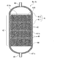
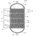
- FIG. 2 is a longitudinal sectional view schematically showing the configuration of the reactor of FIG. 1;
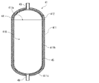
- FIG. 10 is a vertical cross-sectional view schematically showing another configuration of the container;
- FIG. 3 is a cross-sectional view schematically showing the configuration of a reactor provided with a reducing agent layer temperature control section;
- FIG. 4 is a longitudinal sectional view schematically showing another configuration of the gas heating section;
- FIG. 2 is a schematic diagram showing the configuration of an exhaust gas heating unit in FIG. 1;
- FIG. 2 is a longitudinal sectional view schematically showing the configuration of the reactor of FIG. 1;
- FIG. 10 is a vertical cross-sectional view schematically showing another configuration of the container;
- FIG. 3 is a cross-sectional view schematically showing the configuration of a reactor provided with a reducing agent layer temperature control section;
- FIG. 4 is a longitudinal sectional view schematically showing another configuration of the gas heating
- FIG. 4 is a longitudinal sectional view schematically showing another configuration of the gas heating section; It is the schematic which shows 2nd Embodiment of the gas production system of this invention.
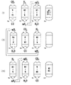
- FIG. 4 is a schematic diagram showing a method of switching gases to be passed through the reactor in the second embodiment
- FIG. 4 is a schematic diagram showing a method of switching gases to be passed through the reactor in the second embodiment
- FIG. 4 is a schematic diagram showing a method of regenerating a reducing agent in the second embodiment
- FIG. 4 is a schematic diagram showing a method of replacing a reducing agent or overhauling a reactor in the second embodiment
- It is a schematic diagram showing the configuration of the reaction section of the third embodiment.
- FIG. 4 is a schematic diagram showing a method of switching gases to be passed through the reactor in the second embodiment
- FIG. 4 is a schematic diagram showing a method of switching gases to be passed through the reactor in the second embodiment
- FIG. 4 is a schematic diagram showing a method of regenerating a reducing agent in the second
- FIG. 11 is a schematic diagram showing a method of switching gases to be passed through the reactor in the third embodiment; It is a schematic diagram showing the configuration of the reaction section of the fourth embodiment.
- FIG. 11 is a schematic diagram showing a method of switching gas to be passed through the reactor in the fourth embodiment;
- FIG. 11 is a schematic diagram showing another method of switching the gas to be passed through the reactor in the fourth embodiment;
- FIG. 11 is a schematic diagram showing the configuration of a reaction section of a fifth embodiment;
- FIG. 11 is a vertical cross-sectional view showing a reactor of a fifth embodiment; It is a graph which shows the temperature change in each measurement location simply.
- FIG. 1 is a schematic diagram showing a first embodiment of the gas production system of the present invention
- FIG. 2 is a schematic diagram showing the configuration of the exhaust gas heating section of FIG. 1
- FIG. 3 is a reactor of FIG. 4 is a longitudinal sectional view schematically showing another structure of the container.
- FIG. A gas production system 100 shown in FIG. I have it.
- the upstream side with respect to the gas flow direction is also simply referred to as the "upstream side”
- the downstream side is simply referred to as the "downstream side”.
- the furnace 20 is not particularly limited, but is, for example, a furnace attached to an ironworks, a refinery, or a thermal power plant, preferably a combustion furnace, a blast furnace, a converter, or the like.
- exhaust gas is produced (generated) during combustion, melting, refining, and the like of the contents.
- the contents include, for example, plastic waste, garbage, municipal waste (MSW), waste tires, biomass waste, household waste (bedding , paper), building materials, and the like.
- these wastes may contain 1 type independently, or may contain 2 or more types.
- Exhaust gases typically contain, in addition to carbon dioxide, other gas components such as nitrogen, oxygen, carbon monoxide, water vapor, methane, and the like.
- concentration of carbon dioxide contained in the exhaust gas is not particularly limited, but considering the production cost of the generated gas (conversion efficiency to carbon monoxide), it is preferably 1% by volume or more, more preferably 5% by volume or more.
- Exhaust gas from a combustion furnace in a garbage incineration plant contains 5-15% by volume of carbon dioxide, 60-70% by volume of nitrogen, 5-10% by volume of oxygen, and 15-25% by volume of water vapor.
- Exhaust gas from a blast furnace is a gas generated when pig iron is produced in a blast furnace, and contains 10 to 15% by volume of carbon dioxide, 55 to 60% by volume of nitrogen, and 25 to 30% by volume of carbon monoxide. , containing 1 to 5% by volume of hydrogen.
- the exhaust gas from the converter is a gas generated when steel is produced in the converter, and contains 15 to 20 volume% carbon dioxide, 50 to 60 volume% carbon monoxide, and nitrogen. It contains 15 to 25% by volume and 1 to 5% by volume of hydrogen.
- the raw material gas is not limited to the exhaust gas, and a pure gas containing 100% by volume of carbon dioxide may be used.
- exhaust gas is used as the raw material gas
- carbon dioxide which has conventionally been discharged into the atmosphere
- the burden on the environment can be reduced.
- exhaust gases containing carbon dioxide generated in steelworks or smelters are preferable.
- the blast furnace gas and the converter gas the untreated gas discharged from the furnace may be used as it is. good.
- the untreated blast furnace gas and the converter gas have gas compositions as described above, and the treated gas has a gas composition close to that shown for the exhaust gas from the combustion furnace.
- all of the above gases (the gases before being supplied to the gas production apparatus 1) are called exhaust gas.
- the gas production apparatus 1 includes an exhaust gas (a raw material gas containing carbon dioxide) discharged from a furnace 20 and supplied through a connection portion 2, and a substance (preferably, a metal oxidation gas) that reduces the carbon dioxide contained in the exhaust gas.
- a product gas (synthesis gas) containing carbon monoxide is produced by contacting the reducing agent 4R containing the substance).
- the gas production apparatus 1 mainly connects a connection portion 2, a reducing gas supply portion 3, two reactors 4a and 4b filled with a reducing agent 4R, and the connection portion 2 and the respective reactors 4a and 4b.
- connection part 2 constitutes a raw material gas supply part for supplying the exhaust gas to the reactors 4a and 4b.
- a pump for transferring gas may be arranged at a predetermined position in the middle of the gas line GL1, the gas line GL2, and the gas line GL4. For example, when the pressure of the exhaust gas is adjusted to be relatively low in the compression unit 6, which will be described later, the gas can be smoothly transferred within the gas production apparatus 1 by arranging a pump.
- Gas line GL1 is connected to connecting portion 2 at one end thereof.
- the other end of the gas line GL1 is connected to inlet ports 48 of the reactors 4a and 4b included in the reaction section 4 via the gas switching section 8 and two gas lines GL3a and GL3b, respectively.
- the gas switching unit 8 can be configured to include, for example, a branch gas line and a channel opening/closing mechanism such as a valve provided in the middle of the branch gas line.
- a concentration adjusting section 5, a compressing section 6, a minor component removing section 7, and an exhaust gas heating section (source gas heating section) 10 are provided in this order from the connecting section 2 side in the middle of the gas line GL1.
- the concentration adjustment unit 5 adjusts so as to increase the concentration of carbon dioxide contained in the exhaust gas (in other words, concentrate the carbon dioxide).
- the exhaust gas also contains unnecessary gas components such as oxygen.
- the concentration adjustment unit 5 is configured by an oxygen removal device that removes oxygen contained in the exhaust gas.
- the amount of oxygen brought into the gas production apparatus 1 can be reduced (that is, the concentration of oxygen contained in the exhaust gas can be adjusted to be low).
- the gas composition of the exhaust gas can be deviated from the explosion range, and ignition of the exhaust gas can be prevented.
- the oxygen removing apparatus consumes a large amount of electrical energy, so it is effective to use electric power as renewable energy as described later.
- the concentration of oxygen contained in the exhaust gas is preferably adjusted to less than 1% by volume, more preferably less than 0.5% by volume, and less than 0.1% by volume with respect to the entire exhaust gas. Adjusting is even more preferable. Thereby, ignition of exhaust gas can be prevented more reliably.
- Oxygen removal equipment for removing oxygen contained in flue gas includes cryogenic (cryogenic) separators, pressure swing adsorption (PSA) separators, membrane separation separators, and temperature swing adsorption (TSA) separators. It can be constructed using one or more of a separator of the type, a separator of the chemical absorption type, a separator of the chemisorption type, and the like. Note that the concentration adjustment unit 5 may adjust the concentration of carbon dioxide to a high level by adding carbon dioxide to the exhaust gas.
- Compressor 6 increases the pressure of the exhaust gas before it is supplied to reactors 4a and 4b. As a result, it is possible to increase the amount of exhaust gas that can be processed at one time in the reactors 4a and 4b. Therefore, the conversion efficiency of carbon dioxide to carbon monoxide in the reactors 4a and 4b can be further improved.
- the compression unit 6 includes, for example, a centrifugal compressor, a turbo compressor such as an axial compressor, a reciprocating compressor (reciprocating compressor), a diaphragm compressor, a single screw compressor, a twin screw compressor, It can be composed of a scroll compressor, a rotary compressor, a rotary piston compressor, a volumetric compressor such as a slide vane compressor, a roots blower (two-leaf blower) capable of handling low pressure, a centrifugal blower, and the like.
- a centrifugal compressor such as an axial compressor, a reciprocating compressor (reciprocating compressor), a diaphragm compressor, a single screw compressor, a twin screw compressor
- It can be composed of a scroll compressor, a rotary compressor, a rotary piston compressor, a volumetric compressor such as a slide vane compressor, a roots blower (two-leaf blower) capable of handling low pressure, a centrifugal blower, and the like.
- the compression unit 6 is preferably configured with a centrifugal compressor from the viewpoint of easiness of increasing the scale of the gas production system 100, and from the viewpoint of reducing the production cost of the gas production system 100, A reciprocating compressor is preferred.
- the pressure of the exhaust gas after passing through the compression unit 6 is not particularly limited, but is preferably 0 to 1 MPaG, more preferably 0 to 0.5 MPaG, and 0.01 to 0.5 MPaG. More preferred. In this case, the conversion efficiency of carbon dioxide to carbon monoxide in the reactors 4a and 4b can be further improved without increasing the pressure resistance of the gas production apparatus 1 more than necessary.
- the minor component removing unit 7 removes minor components (a small amount of unnecessary gas components, etc.) contained in the exhaust gas.
- the fine component removing section 7 can be composed of, for example, at least one processor selected from a gas-liquid separator, a protector (guard reactor) and a scrubber (absorption tower).
- a processor selected from a gas-liquid separator, a protector (guard reactor) and a scrubber (absorption tower).
- the gas-liquid separator separates, for example, condensed water (liquid) generated when the exhaust gas is compressed in the compression section 6 from the exhaust gas.
- the gas-liquid separator can be composed of, for example, a simple container, a swirling flow separator, a centrifugal separator, a surface tension separator, or the like.
- the gas-liquid separator is preferably configured with a simple container because of its simple configuration and low cost.
- a filter may be arranged at the gas-liquid interface in the container to allow passage of gas but block passage of liquid.
- a liquid line may be connected to the bottom of the container, and a valve may be provided in the middle of the line.
- the condensed water stored in the container can be discharged to the outside of the gas production apparatus 1 through the liquid line by opening the valve.
- the liquid line may be connected to a tank 30, which will be described later, so that the discharged condensed water can be reused.
- the exhaust gas from which the condensed water has been removed by the gas-liquid separator can be configured to be supplied to the protector, for example.
- a protector preferably includes a substance capable of capturing a component (inactivating component), which is a minor component contained in the exhaust gas and which reduces the activity of the reducing agent 4R upon contact with the reducing agent 4R.
- the substance in the protector reacts (captures) with the inactivating component, thereby preventing the exhaust gas from reaching the reducing agent 4R in the reactors 4a and 4b. or can be inhibited and protected (ie, prevented from declining in activity). Therefore, it is possible to prevent or suppress an extreme decrease in the conversion efficiency of carbon dioxide to carbon monoxide by the reducing agent 4R due to the adverse effects of the inactivating component.
- Such a substance includes a substance that has a composition contained in the reducing agent 4R and has a composition that reduces the activity of the reducing agent 4R by contact with an inactivating component, for example, a metal oxide that is the same as or Similar metal oxides can be used.
- an inactivating component for example, a metal oxide that is the same as or Similar metal oxides can be used.
- similar metal oxides refer to metal oxides that contain the same metal element but have different compositions, or metal oxides that contain different types of metal elements but belong to the same group in the periodic table. It refers to certain metal oxides.
- the inactivating component is preferably at least one selected from sulfur, mercury, sulfur compounds, halogen compounds, organic silicones, organic phosphorus and organic metal compounds, and at least one selected from sulfur and sulfur compounds. Seeds are more preferred.
- the above substance may be any substance whose activity is lowered by the same component as the inactivating component of the reducing agent 4R. is preferred.
- the protector has a structure in which a mesh material is arranged in a housing, and particles of the above substance are placed on the mesh material.
- a configuration in which a molded body is arranged can be employed.
- a protector is arranged between the compression unit 6 (gas-liquid separator) and the exhaust gas heating unit 10, it is necessary to improve the removal efficiency of the inactivated components while preventing the above substances from deteriorating due to heat. can be done.
- the exhaust gas heating section 10 heats the exhaust gas before it is supplied to the reactors 4a and 4b.
- the exhaust gas heating section 10 can be configured with an electric heater 101 and a heat exchanger (economizer) 102 .
- the heat exchanger 102 bends a part of the pipe that constitutes the gas line GL4 (see below) for discharging the gas (mixed gas) after passing through the reactors 4a and 4b, and bends the pipe that constitutes the gas line GL1.
- the heat (sensible heat and/or latent heat) of the high-temperature gas (mixed gas) after passing through the reactors 4a and 4b is used to heat the exhaust gas before being supplied to the reactors 4a and 4b. Since heating is performed by heat exchange, effective use of heat can be achieved. It is also possible to burn a reducing gas such as hydrogen or ammonia with a burner or the like and use the combustion heat as a heat source for heat exchange with the exhaust gas.
- a reducing gas such as hydrogen or ammonia
- the heat exchanger 102 is, for example, a jacket heat exchanger, an immersion coil heat exchanger, a double tube heat exchanger, a shell and tube heat exchanger, a plate heat exchanger, a spiral heat exchanger, or the like.
- a combustion furnace or the like can be used in the exhaust gas heating section 10.
- electric power electrical energy
- renewable energy electrical energy using at least one selected from solar power, wind power, hydraulic power, wave power, tidal power, biomass power, geothermal power, solar heat, and underground heat is used. It is possible.
- the exhaust gas line is branched from the gas line GL1, and the gas A vent portion provided outside the manufacturing apparatus 1 may be connected.
- a valve is preferably provided in the middle of the exhaust gas line. If the pressure in the gas production device 1 (gas line GL1) rises more than necessary, the valve is opened to discharge (release) part of the exhaust gas from the vent through the exhaust gas line. be able to. As a result, it is possible to prevent damage to the gas production device 1 due to an increase in pressure.
- the gas line GL2 is connected to the reducing gas supply section 3 .
- the gas line GL2 is connected at the other end to the inlet ports 48 of the reactors 4a and 4b provided in the reaction section 4 via the gas switching section 8 and the two gas lines GL3a and GL3b. It is connected to the.
- the reducing gas supply unit 3 supplies a reducing gas containing a reducing substance that reduces the reducing agent 4R oxidized by contact with carbon dioxide.
- the reducing gas supply unit 3 of the present embodiment is composed of a hydrogen generator that generates hydrogen by electrolysis of water. 30 are connected.
- the reducing gas containing hydrogen (reducing substance) supplied from the hydrogen generator (reducing gas supply unit 3) passes through the gas line GL2 and is supplied to the reactors 4a and 4b.
- the hydrogen generator a large amount of hydrogen can be generated relatively inexpensively and easily.
- the condensed water generated in the gas production apparatus 1 can be reused.
- the hydrogen generator consumes a large amount of electrical energy, so it is effective to use electric power as renewable energy as described above.
- a device that generates by-product hydrogen can also be used as the hydrogen generator.
- a reducing gas containing by-product hydrogen is supplied to each reactor 4a, 4b.
- a device for generating by-product hydrogen for example, a device for electrolyzing an aqueous solution of sodium chloride, a device for steam reforming petroleum, a device for producing ammonia, and the like can be mentioned.
- the gas line GL2 may be connected to the coke oven outside the gas production apparatus 1 via a connecting portion, and the exhaust gas from the coke oven may be used as the reducing gas.
- the connecting portion constitutes the reducing gas supply portion.
- a reducing gas heating unit 11 is provided in the middle of the gas line GL2. This reducing gas heating unit 11 heats the reducing gas before it is supplied to the reactors 4a and 4b. By preheating the reducing gas before reaction (before oxidation) in the reducing gas heating unit 11, the reduction (regeneration) reaction of the reducing agent 4R by the reducing gas in the reactors 4a and 4b can be further promoted.
- the reducing gas heating section 11 can be configured in the same manner as the exhaust gas heating section 10 described above.
- the reducing gas heating unit 11 is preferably composed of only an electric heater, only a heat exchanger, or a combination of an electric heater and a heat exchanger, and may be composed of only a heat exchanger or a combination of an electric heater and a heat exchanger. is more preferred. If the reducing gas heating unit 11 is equipped with a heat exchanger, the heat of the high-temperature gas (for example, mixed gas) after passing through the reactors 4a and 4b is used to heat the gas before supplying it to the reactors 4a and 4b. Since the reducing gas is heated by heat exchange, effective use of heat can be achieved.
- the high-temperature gas for example, mixed gas
- Gas lines GL4a and GL4b are connected to the outlet ports 49 of the reactors 4a and 4b, respectively, and are merged at the gas junction J4 to form one gas line GL4. Further, valves (not shown) are provided in the middle of the gas lines GL4a and GL4b, respectively, as required. For example, by adjusting the opening of the valves, the passage speed of the exhaust gas and the reducing gas passing through the reactors 4a and 4b (that is, the processing speed of the exhaust gas with the reducing agent 4R and the processing speed of the reducing agent 4R with the reducing gas) can be changed. can be set.
- the reaction section 4 is configured by the reactors 4 a and 4 b and the gas switching section 8 .
- the gases mainly carbon monoxide and water vapor in this embodiment
- the gases that have passed through each of the reactors 4a and 4b are mixed at the gas junction J4 to form a mixed gas (merged gas).
- a mixed gas merged gas
- the mixed gas can be continuously produced, and the final In practice, the product gas can also be produced continuously.
- the concentration of carbon monoxide contained in the mixed gas is stabilized, and as a result, the concentration of carbon monoxide contained in the produced gas is stabilized. It can also be made into Therefore, the gas production apparatus 1 (gas production system 100) described above can continuously and stably produce carbon monoxide from carbon dioxide, which is industrially advantageous.
- the concentration of carbon monoxide contained in the mixed gas is usually preferable to adjust the concentration of carbon monoxide contained in the mixed gas within a specific range (predetermined volume % with respect to the entire mixed gas). If this concentration is too low, it tends to be difficult to obtain a generated gas containing a high concentration of carbon monoxide, depending on the performance of the gas refiner 9, which will be described later. On the other hand, even if the concentration exceeds the upper limit, the effect of further increasing the concentration of carbon monoxide contained in the finally obtained product gas cannot be expected to increase any further.
- a generated gas discharge section 40 for discharging the generated gas to the outside of the gas production apparatus 1 is connected to the end of the gas line GL4 opposite to the reactors 4a and 4b.
- a gas refining section 9 is provided in the middle of the gas line GL4.
- the gas purification unit 9 purifies carbon monoxide from the mixed gas and recovers a generated gas containing high-concentration carbon monoxide. Incidentally, if the carbon monoxide concentration in the mixed gas is sufficiently high, the gas refining section 9 may be omitted.
- the gas purifying section 9 can be composed of, for example, at least one processor selected from coolers, gas-liquid separators, gas separators, separation membranes, and scrubbers (absorption towers).
- processors When a plurality of processors are used, their arrangement order is arbitrary, but when a cooler, a gas-liquid separator and a gas separator are used in combination, they are preferably arranged in this order. In this case, the efficiency of purifying carbon monoxide from the mixed gas can be further enhanced.
- a cooler cools the mixed gas. This produces condensed water (liquid).
- Such coolers include a jacket-type cooling device in which a jacket for passing the refrigerant around the pipe is arranged, a multi-pipe cooling device in which the mixed gas is passed through the pipe and the refrigerant is passed around the pipe, air It can be configured to include a fin cooler or the like.
- the gas-liquid separator separates from the mixed gas condensed water produced when the mixed gas is cooled by the cooler.
- the condensed water has the advantage of being able to dissolve and remove unnecessary gas components (particularly carbon dioxide) remaining in the mixed gas.
- the gas-liquid separator can be configured in the same manner as the gas-liquid separator of the micro component removing section 7, and preferably can be configured as a simple container.
- a filter may be arranged at the gas-liquid interface in the container to allow passage of gas but block passage of liquid.
- a liquid line may be connected to the bottom of the container, and a valve may be provided in the middle of the line. According to such a configuration, the condensed water stored in the container can be discharged (released) out of the gas production apparatus 1 through the liquid line by opening the valve.
- a drain trap downstream of the valve in the liquid line it is preferable to provide a drain trap downstream of the valve in the liquid line.
- a drain trap downstream of the valve in the liquid line.
- the liquid line may be connected to the tank 30 described above to reuse the discharged condensed water.
- Gas separators include, for example, cryogenic (cryogenic) separators, pressure swing adsorption (PSA) separators, membrane separation separators, temperature swing adsorption (TSA) separators, metal ion (e.g., copper ions) and organic ligands (e.g., 5-azidoisophthalic acid) are combined into a separator using a porous coordination polymer (PCP), and separation using amine absorption. It can be configured using one or more of the vessels and the like.
- a valve may be provided between the gas-liquid separator and the gas separator of the gas line GL4. In this case, the mixed gas processing speed (production gas production speed) can be adjusted by adjusting the opening of the valve.
- the concentration of carbon monoxide contained in the mixed gas discharged from the gas-liquid separator is 75 to 90% by volume with respect to the entire mixed gas. Therefore, in fields where a produced gas containing carbon monoxide in a relatively low concentration (75 to 90% by volume) can be used, the carbon monoxide can be directly supplied to the next step without purification from the mixed gas. That is, the gas separator can be omitted.
- Such fields include, for example, the field of synthesizing valuable substances (e.g., ethanol, etc.) from the produced gas by fermentation with microorganisms (e.g., Clostridium, etc.), the field of producing steel using the produced gas as a fuel or reducing agent, Examples include the field of manufacturing electric devices and the field of synthesizing chemicals (phosgene, acetic acid, etc.) using carbon monoxide as a synthetic raw material.
- valuable substances e.g., ethanol, etc.
- microorganisms e.g., Clostridium, etc.
- Examples include the field of manufacturing electric devices and the field of synthesizing chemicals (phosgene, acetic acid, etc.) using carbon monoxide as a synthetic raw material.
- the carbon monoxide is purified from the mixed gas to produce a product gas containing high concentrations of carbon monoxide.
- Such fields include, for example, the field of using generated gas as a reducing agent (blast furnace), the field of thermal power generation using generated gas as fuel, the field of manufacturing chemicals using generated gas as a raw material, and the field of manufacturing chemicals using generated gas as fuel. and the field of fuel cells used as
- the configuration of the reactors 4a and 4b has the following characteristics as an example.
- the reactors 4a and 4b shown in FIG. 3 include a container 41 having a single internal space 410 through which gas can pass, and a reducing agent layer (filling layer) filled in the internal space 410 and composed of a particulate reducing agent 4R. and at least one (three in this embodiment) gas diffusion plate 43 provided in the middle of the reducing agent layer 42 in the direction of gas passage (vertical direction in FIG. 3) to diffuse the gas. It has The number of gas diffusion plates 43 to be installed may be two, or may be four or more.
- a support plate 44 that supports the reducing agent layer 42 is provided inside the container 41 (internal space 410 ).
- the configuration of the reactors 4a, 4b can be simplified. Further, since the entire container 41 can be made of a single material, there is no need to consider the difference in coefficient of thermal expansion of each part, and a material with high heat resistance can be used as the constituent material of the container 41 . As a result, the reaction temperature in the reactors 4a and 4b can be made sufficiently higher than the reaction temperature in the conventional reactor, so that the conversion efficiency of carbon dioxide to carbon monoxide can be enhanced. Similarly, it is possible to increase the efficiency of regeneration (reduction) of the reducing agent 4R by the reducing gas containing the reducing substance.
- the container 41 has a bottomed cylindrical container body 411 having an opening 411a, and a lid 412 detachably attached to the container body 411 so as to close the opening 411a.
- the container main body 411 has a trunk portion 411b which is open at one end with an opening portion 411a and closed at the other end with a bottom portion 411c.
- the lid body 412 is fixed to the container body 411 by, for example, bolts or the like.
- the shape of the bottom portion 411c of the container body 411 and the lid 412 are each dome-shaped (curved convex shape), but they can also be flat plate-shaped. If the bottom portion 411c is flat, the support plate 44 for supporting the reducing agent layer 42 can be omitted.
- An inlet port 48 is provided near the top of the lid 412, and an outlet port 49 is provided near the top of the bottom 411c. The gas supplied from the inlet port 48 passes through the inner space 410 downward through the reducing agent layer 42 and is discharged from the outlet port 49 .
- the constituent material of the container 41 may be selected according to the properties and reactivity of the gas to be passed, and is not particularly limited, but examples include carbon steel, stainless steel, nickel, and the like. Metal materials with high heat resistance such as alloys and molybdenum alloys can be used. These metal materials may be used singly or in combination of two or more. Since carbon steel and stainless steel are relatively inexpensive, the manufacturing cost of the reactors 4a and 4b can be reduced. On the other hand, although nickel alloys and molybdenum alloys are expensive, the structure of the container 41 can be simplified, the amount used can be reduced, and the production costs of the reactors 4a and 4b can also be reduced. Among these, the container 41 is preferably made of at least one of carbon steel and stainless steel. By using the metal materials described above, the reaction temperature in the reactors 4a and 4b can be increased to about 850.degree.
- the container 41 having the configuration shown in FIG. 4 can be employed.
- a container 41 shown in FIG. 4 is provided with a heat-resistant structure 45 having a heat-resistant temperature higher than that of the container 41 on its inner surface.
- the heat-resistant structure 45 can be composed of, for example, firebricks, heat-insulating firebricks, shaped refractories such as pre-block cast, fireproof mortar, monolithic refractories such as castable, and the like.
- the reactors 4a, 4b can be used at a temperature of 700-1200° C. (preferably 800-1100° C., more preferably 900-1000° C.).
- the heat-resistant structure 45 is not limited to the entire inner surface of the container 41, and may be provided only on at least a portion thereof (the inner surface of the body portion 411b).
- the inner diameter and height of the body portion 411b (internal space 410) of the container body 411 are appropriately set according to the supply amount of the exhaust gas, and are not particularly limited.
- the ratio of height to inner diameter (height/inner diameter) is preferably designed to be large (designed to be large in the height direction) from the viewpoint of enhancing gas dispersibility, and is usually designed to be 2-10.
- a reducing agent layer 42 is formed by filling the container 41 (single internal space 410) with a particulate (granular) reducing agent 4R. Therefore, in the reducing agent layer 42, the spaces between the reducing agents 4R are connected in the horizontal direction (the direction perpendicular to the gas passage direction). With such a reducing agent layer 42 , the filling efficiency into the container 41 can be increased, and the contact area with the gas supplied into the container 41 can be further increased.
- the volume average particle size of the reducing agent 4R is not particularly limited, but is preferably 1 to 50 mm, more preferably 3 to 30 mm.
- the contact area between the reducing agent 4R and the exhaust gas (carbon dioxide) can be further increased, and the conversion efficiency of carbon dioxide to carbon monoxide can be further improved.
- the regeneration (reduction) of the reducing agent 4R by the reducing gas containing the reducing substance can be performed more efficiently.
- the particulate reducing agent 4R is preferably a compact produced by tumbling granulation, since the degree of sphericity is increased.
- the reducing agent 4R may be configured by supporting a substance (preferably a metal oxide) that reduces carbon dioxide on a carrier.
- the constituent material of the carrier is not particularly limited as long as it is difficult to denature depending on the exhaust gas (raw material gas), reaction conditions, etc., but examples include carbon materials (graphite, graphene, etc.), zeolite, montmorillonite, silica ( SiO 2 ), ZrO 2 , TiO 2 , V 2 O 5 , MgO, alumina (Al 2 O 3 ), composite oxides thereof, and the like.
- zeolite, montmorillonite, silica (SiO 2 ), ZrO 2 , TiO 2 , V 2 O 5 , MgO, alumina (Al 2 O 3 ), and composite oxides thereof are preferable as the constituent material of the carrier.
- a carrier composed of such a material is preferable because it does not adversely affect the reaction of the carbon dioxide-reducing substance and is excellent in the ability to support the carbon dioxide-reducing substance.
- the carrier simply supports (holds) the substance without participating in the reaction of the substance.
- An example of such a form includes a configuration in which at least part of the surface of the carrier is coated with the substance.
- the metal oxide (oxygen carrier), which is an example of a substance that reduces carbon dioxide, is not particularly limited as long as it can reduce carbon dioxide, but at least one selected from metal elements belonging to Groups 3 to 12 It is preferable to contain a seed, more preferably at least one selected from metal elements belonging to Groups 4 to 12, titanium, vanadium, iron, copper, zinc, nickel, manganese, chromium and It is more preferable to contain at least one of cerium and the like, and metal oxides or composite oxides containing iron are particularly preferable. These metal oxides are useful because they are particularly efficient in converting carbon dioxide to carbon monoxide.
- the ratio of the cross-sectional area of the reducing agent layer 42 to the cross-sectional area of the internal space 410 (in other words, the ratio of the cross-sectional area of the reducing agent layer 42 to the cross-sectional area of the internal space 410).
- the ratio of agent 4R) is 60% or more, preferably 75% or more, and more preferably 85% or more. As a result, the chances of contact between the gas passing through the internal space 410 and the reducing agent 4R can be increased.
- the upper limit of the ratio is preferably 99% or less, more preferably 95% or less. In this case, it is possible to prevent the passage resistance of the gas passing through the internal space 410 from increasing more than necessary.
- the ratio of the volume of the reducing agent layer 42 to the volume of the internal space 410 is preferably 50-90%, more preferably 55-85%, and even more preferably 60-80%. In this case, the chances of contact between the gas passing through the internal space 410 and the reducing agent 4R can be increased while preventing the passage resistance of the gas passing through the internal space 410 from increasing more than necessary.
- the support plate 44 has its peripheral portion engaged with the boundary portion (shoulder portion) between the trunk portion 411b and the bottom portion 411c. Thereby, the support plate 44 is positioned in the gas passage direction with respect to the container body 411 .
- This support plate 44 can be composed of, for example, a perforated plate having a plurality of through holes, a mesh material, or the like.
- the gas diffusion plate 43 has a function of diffusing the gas passing through the reducing agent layer 42 and making it uniform in the in-plane direction (horizontal direction). By arranging the gas diffusion plate 43, the gas passing through the internal space 410 and the reducing agent 4R can be brought into uniform contact.
- This gas diffusion plate 43 can be composed of, for example, a perforated plate having a plurality of through holes.
- the gas diffusion plate 43 is separated from the container 41 (container body 411).
- the support plate 44 has its peripheral portion engaged with the boundary portion (shoulder portion) between the trunk portion 411b and the bottom portion 411c. That is, neither the gas diffusion plate 43 nor the support plate 44 is fixed to the container 41 . Therefore, even if the coefficient of thermal expansion of the gas diffusion plate 43 and the support plate 44 and the coefficient of thermal expansion of the container 41 differ greatly, the reactors 4a and 4b are less likely to be damaged by heating or heat generated during the gas reaction. can be done.
- the gas diffusion plate 43 may be arranged on the upstream side of the reducing agent layer 42 in the gas passage direction.
- the gas diffusion plate 43 provided in the middle of the reducing agent layer 42 in the gas passage direction may be omitted.
- the volumes of the two reactors 4a and 4b are set substantially equal to each other, and are appropriately set according to the amount of exhaust gas to be treated (the size of the furnace 20 and the size of the gas production apparatus 1).
- the usage (action) of the gas production system 100 of the first embodiment that is, the gas production method will be described.
- the exhaust gas supplied from the furnace 20 is normally at a high temperature of 50-300° C., but is cooled to 30-50° C. before reaching the concentration adjusting section 5 .
- the exhaust gas passes through the oxygen removing device (concentration adjusting section 5). Oxygen is thereby removed from the exhaust gas, and the concentration of carbon dioxide contained in the exhaust gas increases.
- the exhaust gas passes through the compression section 6 . This increases the pressure of the exhaust gas.
- the exhaust gas passes through the minor component removing section 7 . As a result, the condensed water generated when the exhaust gas is compressed in the compression unit 6 and the inactivating components that reduce the activity of the reducing agent 4R are removed from the exhaust gas.
- the exhaust gas passes through the exhaust gas heating section 10 . This heats the exhaust gas.
- the exhaust gas is supplied to the reactor 4a.
- the carbon dioxide in the exhaust gas is reduced to carbon monoxide by the reducing agent 4R.
- the reducing agent 4R is oxidized.
- the reduction reaction itself from carbon dioxide to carbon monoxide is usually an endothermic reaction, but the reduction reaction from carbon dioxide to carbon monoxide with the reducing agent 4R (oxygen carrier) is often an exothermic reaction.
- the reduction reaction of the exhaust gas in the chemical looping reaction is preferably set to a lower temperature than the oxidation reaction by the reducing gas.
- the heating temperature of the exhaust gas in the above step [6] is preferably set to be lower than the heating temperature of the reducing gas in the following step [9] by 30° C. or more (preferably about 50 to 100° C.). This can prevent the reducing agent layer 42 in the reactor 4a from becoming unnecessarily hot in the above reaction. As a result, alteration and deterioration of the reducing agent 4R can be suppressed.
- the specific value of the heating temperature of the exhaust gas in the step [6] is preferably 550 to 1000°C, more preferably 600 to 900°C, even more preferably 650 to 800°C.
- the heating temperature of the exhaust gas within the above range, for example, the reduction reaction of carbon dioxide (first substrate gas) in the reactor 4a can proceed more smoothly.
- the temperature of the reducing agent layer 42 of the reactor 4a at the start of the step [7] is 30° C. or more (preferably, about 50 to 100° C.).
- the specific value of the temperature of the reducing agent layer 42 of the reactor 4a is the same as the specific value of the heating temperature of the exhaust gas. Thereby, the same effect as described above can be obtained.
- the heating temperature of the reducing gas and the temperature of the reducing agent layer 42 of the reactor 4b are set within the above ranges, for example, the reducing agent 4R can be rapidly heated by an endothermic reaction when reducing (regenerating) the reducing agent 4R in an oxidized state. Since the temperature drop can be prevented or suppressed, the reduction reaction of the reducing agent 4R in the reactor 4b can proceed more smoothly.
- the switching timing of the gas lines in the gas switching unit 8 (that is, the switching timing of the exhaust gas and the reducing gas supplied to the reactors 4a and 4b) is determined by condition I: a predetermined amount of gas is supplied to the reactor 4a or 4b. Preferably, it is when the exhaust gas is supplied, or Condition II: when the conversion efficiency of carbon dioxide to carbon monoxide is below a predetermined value.
- condition I a predetermined amount of gas is supplied to the reactor 4a or 4b.
- Condition II when the conversion efficiency of carbon dioxide to carbon monoxide is below a predetermined value.
- gas concentration sensors may be arranged near the inlet port 48 and the outlet port 49 of the reactors 4a and 4b, respectively. Based on the detected value of this gas concentration sensor, the conversion efficiency of carbon dioxide to carbon monoxide can be obtained by calculation.
- the amount of exhaust gas supplied to the reactors 4a and 4b and the amount of reducing gas supplied to the reactors 4a and 4b can be It is preferable to set them as close as possible.
- P/Q preferably satisfies the relationship of 0.7 to 1.1, and more preferably satisfies the relationship of 0.85 to 1.05. If the exhaust gas supply amount P is too large, the amount of carbon dioxide discharged from the reactors 4a and 4b increases without being converted to carbon monoxide, depending on the amount of the reducing agent 4R in the reactors 4a and 4b. tend to
- the predetermined amount in the above condition I is preferably an amount of carbon dioxide of 0.01 to 3 mol, 0.1 to 2.5 mol, per 1 mol of the metal element that accounts for the largest mass ratio in the reducing agent 4R. Molar amounts are more preferred.
- the predetermined value in Condition II is preferably 50 to 100%, more preferably 60 to 100%, even more preferably 70 to 100%. Note that the upper limit of the predetermined value may be 95% or less, or 90% or less. In either case, it is possible to switch the reactors 4a and 4b before the conversion efficiency of carbon dioxide to carbon monoxide drops extremely, and as a result, the mixed gas containing a high concentration of carbon monoxide is stabilized. and thus produce a product gas containing a high concentration of carbon monoxide.
- the supply amount Q of the reducing gas is preferably 0.1 to 3 mol of hydrogen per 1 mol of the metal element that accounts for the largest mass ratio in the reducing agent 4R, and is preferably 0.15. More preferred is an amount of ⁇ 2.5 moles. Even if the supply amount Q of the reducing gas is increased beyond the upper limit, no further increase in the effect of reducing the oxidized reducing agent 4R can be expected. On the other hand, if the supply amount Q of the reducing gas is too small, the reduction of the reducing agent 4R may be insufficient depending on the amount of hydrogen contained in the reducing gas.
- the pressure of the reducing gas supplied to the reactors 4a and 4b may be atmospheric pressure or pressurized (same as the exhaust gas).
- the gases that have passed through the reactors 4a and 4b join together to produce a mixed gas.
- the temperature of the mixed gas is typically 600-1000°C. If the temperature of the mixed gas at this time is within the above range, it means that the temperature in the reactors 4a and 4b is maintained at a sufficiently high temperature, and the conversion of carbon dioxide to carbon monoxide by the reducing agent 4R Also, it can be determined that the reduction of the reducing agent 4R by the reducing gas is progressing efficiently.
- the mixed gas is cooled to 100 to 300° C. before reaching the gas refining section 9 .
- the mixed gas passes through the gas refining section 9 .
- the generated condensed water and carbon dioxide dissolved in the condensed water are removed.
- carbon monoxide is purified from the mixed gas to obtain a product gas containing a high concentration of carbon monoxide.
- the temperature of the produced gas obtained is 20 to 50°C.
- FIG. 5 is a cross-sectional view schematically showing the configuration of a reactor provided with a reducing agent layer temperature control section.
- the reducing agent layer temperature control unit shown in FIG. 5 has one tubular body 401 which is provided in contact with (penetrates through) the reducing agent layer 42 and transfers a temperature control medium for adjusting the temperature of the reducing agent layer 42 .
- the reducing agent layer temperature control section further includes a circulating or closed medium line 402 connected to both ends of the tubular body 401, and the medium line 402 is filled with a temperature control medium.
- a transfer device 403 for transferring the temperature control medium and a temperature control device 404 for adjusting (heating or cooling) the temperature of the temperature control medium are provided.
- the transfer device 403 and the temperature control device 404 may be inside or outside the reactor.
- the reducing agent layer 42 can be indirectly heated or cooled through the tube 401 when the temperature control medium temperature-controlled by the temperature control device 404 circulates through the medium line 402 . .
- the area of the space through which the temperature control medium passes can be made sufficiently small relative to the cross-sectional area of the container 41, as compared with the multi-tubular reactor.
- the constituent material of the tubular body 401 is preferably a material having a thermal expansion coefficient that is the same as or substantially equal to that of the container 41 , more preferably the same material as the container 41 .
- the transfer device 403 can be composed of a blower. Further, when a liquid is used as the temperature control medium, the transfer device 403 can be configured with a pump.
- FIG. 1 shows an exhaust gas heating unit 10 and a reducing gas heating unit 11 installed upstream of the gas switching unit 8 as gas heating units for heating the gas (exhaust gas and reducing gas) before passing through the reducing agent layer 42 . showed that.
- the branch gas lines constituting the gas switching section 8 and the gas lines GL3a and GL3b immediately before the reactors 4a and 4b, such as the reactors 4a and 4b. It may be installed in the gas line connected to the inlet port 48 . 8, 13, 15 and 18, which will be described later, are the same.
- the gas heating unit in this case can be composed of at least one selected from a heat exchanger similar to that shown in FIG. 2, an electric heater, and a microwave irradiator to be described later.
- the gas heating unit may be incorporated in the reactors 4a and 4b.
- the structures shown in FIGS. 6 and 7 are exemplified, but not limited thereto. 6 and 7 are longitudinal sectional views schematically showing other configurations of the gas heating section.
- the gas heating part shown in FIG. 6 includes a heat conductor 4D filled in the internal space 410 on the upstream side of the gas passage direction from the reducing agent layer 42, and a microwave provided in the container main body 411 for heating the heat conductor 4D. It is composed of a microwave irradiator 471 capable of irradiating waves. According to such a configuration, even the central part of the heat conductor 4D can be uniformly heated in a relatively short time. Moreover, it is easy to precisely control the heating temperature of the heat conductor 4D. Therefore, the exhaust gas and the reducing gas can be rapidly heated to desired temperatures.
- constituent materials of the heat conductor 4D include carbon materials (graphite, graphene, etc.), zeolite, montmorillonite, silica (SiO 2 ), ZrO 2 , TiO 2 , V 2 O 5 , MgO, alumina (Al 2 O 3 ), their composite oxides, and the like.
- carbon materials graphite, graphene, etc.
- zeolite, montmorillonite, silica ( SiO2 ), ZrO2, TiO2 , V2O5 , MgO, alumina ( Al2O3 ) , and composite oxides thereof are preferred.
- the shape of the heat conductor 4D is preferably particulate (granular), scale-like, pellet-like, or the like, for example. With the heat conductor 4D having such a shape, the contact area with the gas supplied into the internal space 410 can be further increased.
- the volume average particle size of the heat conductor 4D is preferably larger than the volume average particle size of the reducing agent 4R.
- the volume average particle size of the heat conductor 4D is not particularly limited, but is preferably 5 to 100 mm, more preferably 10 to 70 mm.
- Microwave means electromagnetic waves with a frequency of 300 MHz to 300 GHz, ultra high frequency (UHF) with a frequency of 300 to 3000 MHz, centimeter wave (SHF) with a frequency of 3 to 30 GHz, millimeter wave (EHF) with a frequency of 30 to 300 GHz, frequency 300 It is classified as submillimeter wave (SHF) of ⁇ 3000 GHz.
- ultrahigh frequency (UHF) is preferable as the microwave.
- UHF ultrahigh frequency
- the heat conductor 4D can be heated to the desired temperature in a shorter time.
- the container 41 is appropriately protected against leakage of radio waves in compliance with the Radio Law. Further, the microwave irradiation may be performed continuously or intermittently (in pulses).
- the microwave irradiator 471 may be arranged in the lid 412 instead of the container body 411 , may be arranged in the internal space 410 , or may be arranged outside the container 41 .
- the gas composition of the exhaust gas is deviated from the explosion range by the concentration adjustment unit 5, it is possible to suitably prevent the exhaust gas from becoming an ignition source regardless of the microwave irradiation conditions. .
- electrical energy is used as a power source for the microwave irradiator 471, there is also the advantage that this electrical energy can be easily switched to renewable energy.
- the gas heating part shown in FIG. 7 is separated from the reducing agent layer 42 and is provided to pass through an internal space 410 on the upstream side of the reducing agent layer 42 in the direction of passage of the gas. 472.
- the gas heating section further comprises a circulating medium line 473 connected to both ends of the tubular body 472, and the medium line 473 is filled with the medium.
- a transfer device 474 for transferring the medium and a heating device 475 for heating the medium are provided in the middle of the medium line 473 .
- the gas passing through the space above the reducing agent layer 42 in the internal space 410 (that is, the gas passing through the reducing agent layer 42 is gas) can be indirectly heated via tube 472 .
- the constituent material of the tubular body 472 is preferably a material having a coefficient of thermal expansion that is the same as or substantially equal to that of the constituent material of the container 41 , more preferably the same material as the constituent material of the container 41 .
- the heating device 475 can be composed only of an electric heater, or can be composed of an electric heater and a heat exchanger similar to that described for the exhaust gas heating section 10 . According to the latter configuration, the heat of the high-temperature gas after passing through the reactors 4a and 4b is used to heat the medium before being supplied to the reactors 4a and 4b by heat exchange, so that heat can be effectively utilized. can be achieved.
- the transfer device 474 can be configured with a blower.
- the transfer device 474 can be configured with a pump.
- the generated gas produced using the gas production apparatus 1 and the gas production system 100 usually has a carbon monoxide concentration of 60% by volume or more, preferably 75% by volume or more, more preferably 90% by volume or more.
- the generated gas as described above is used in the field of synthesizing valuable substances (e.g., ethanol, etc.) by fermentation with microorganisms (e.g., Clostridium, etc.), in the field of manufacturing steel using it as a fuel or reducing agent, and in the field of electric devices.
- phosgene, acetic acid, etc. phosgene, acetic acid, etc.
- FIG. 8 is a schematic diagram showing a second embodiment of the gas production system of the present invention
- FIGS. 9 and 10 are schematic diagrams respectively showing a method of switching the gas to be passed through the reactor in the second embodiment.
- 11 is a schematic diagram showing a method of regenerating the reducing agent in the second embodiment
- FIG. 12 is a schematic diagram showing a method of replacing the reducing agent or overhauling the reactor in the second embodiment.
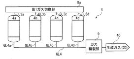
- the reaction section 4 shown in FIG. 8 has four reactors 4a to 4d.
- the configuration of each of the reactors 4a to 4d can be the same configuration as the reactors 4a and 4b described in the first embodiment.
- Gas line GL1 is connected at its end opposite to connecting portion 2 to inlet ports 48 of reactors 4a to 4d via first gas switching portion 8a and four gas lines GL3a to GL3d, respectively. .
- the exhaust gas supplied from the furnace 20 through the connecting part 2 passes through the gas line GL1 and is supplied to each of the reactors 4a to 4d.
- the configuration of the first gas switching section 8a can be the same as that of the gas switching section 8 described in the first embodiment.
- the gas line GL2 is connected to the reactors 4a to 4d via the first gas switching unit 8a and the four gas lines GL3a to GL3d, similarly to the gas line GL1. It is connected to inlet port 48 . Lines GL4a to GL4d are connected to the outlet ports 49 of the reactors 4a to 4d, respectively, and joined at the second gas switching section 8b to form one gas line GL4. Further, valves (not shown) are provided in the middle of the gas lines GL4a to GL4d, respectively, as required.
- the reaction section 4 is composed of the reactors 4a to 4d, the first gas switching section 8a and the second gas switching section 8b.
- the reaction section 4 of this embodiment also has four gas lines GL5a to GL5d connecting between the first gas switching section 8a and the second gas switching section 8b.
- one reactor of the reactors 4a to 4d can supply exhaust gas (second 1 substrate gas) can be supplied and passed through, while the reducing gas (second substrate gas) can be continuously supplied and passed through the remaining three reactors of the reactors 4a to 4d in this order.
- one of the plurality of reactors 4a to 4d to which the exhaust gas is supplied is the first reactor, and the reducing gas is continuously supplied when the exhaust gas is supplied to the first reactor.
- the three reactors fed with are the second reactors.
- the exhaust gas (carbon dioxide) is supplied to the reactor (first reactor) 4a through the gas line GL3a, and the exhaust gas (first carbon oxides) can be discharged via gas line GL4a.
- a reducing gas (hydrogen) is supplied to the reactor (first second reactor) 4b through the gas line GL3b, and then the reduction Gas (residual hydrogen) is supplied to reactor (second reactor) 4c through gas line GL4b, gas line GL5c, and gas line GL3c, and then reducing gas (residual hydrogen) that has passed through this is supplied to It is supplied to the reactor (third second reactor) 4d via the gas line GL4c, the gas line GL5d and the gas line GL3d, and the reducing gas (water) that has passed through this is discharged via the gas line GL4d. be able to.
- the exhaust gas is supplied to and passed through the reactor (first reactor) 4b, while the reactors (second reactors) 4c, 4d, 4a , the reducing gas can be continuously supplied and passed through in this order.
- the exhaust gas is supplied to and passed through the reactor (first reactor) 4c, while the reactors (second reactors) 4d, 4a, 4b , the reducing gas can be continuously supplied and passed through in this order.
- the exhaust gas is supplied to and passed through the reactor (first reactor) 4d, while the reactors (second reactors) 4a, 4b, 4c , the reducing gas can be continuously supplied and passed through in this order.
- a series of operations from the first turn to the fourth turn are regarded as one cycle, and by repeating a plurality of cycles, carbon dioxide can be continuously and stably converted into carbon monoxide.
- a reducing agent 4R whose oxidation state reduction efficiency by hydrogen (reducing substance) is lower than the conversion efficiency of carbon dioxide to carbon monoxide
- the reducing gas can be passed through three reactors in succession, in other words, it can be passed through one reactor three times. Therefore, hydrogen (reducing gas) can be prevented from being wasted.
- a pattern as shown in FIG. 10 can also be used. That is, in the pattern shown in FIG. 10, for example, the exhaust gas with a temperature of 700° C. is heated to 800° C. by an exothermic reaction when passing through the reactor, and the reducing gas with a temperature of 800° C. is cooled to 760°C by an endothermic reaction, cooled to 730°C by an endothermic reaction when passing through the second-stage reactor, and cooled to 700°C by an endothermic reaction when passing through the third-stage reactor. is set as In this case, at the end of the first turn shown in FIG. The temperature of the reducing agent layer 42 is 730°C, and the temperature of the reducing agent layer 42 in the reactor 4d is 700°C.
- the temperature of the reducing agent layer 42 of the reactor 4d becomes a temperature suitable for supplying the exhaust gas
- the temperature of the reducing agent layer 42 of the reactor 4a becomes suitable for supplying the initial (fresh) reducing gas. temperature. Therefore, in the second turn shown in FIG. 10(II), the exhaust gas is passed through the reactor 4d, and the reducing gas is passed through the reactors 4a, 4b and 4c in this order. Thereafter, in the third turn shown in FIG. 10(III), the exhaust gas is passed through the reactor 4c, and the reducing gas is passed through the reactors 4d, 4a and 4b in this order. In the fourth turn shown in FIG. 10(IV), the exhaust gas is passed through the reactor 4b, and the reducing gas is passed through the reactors 4c, 4d and 4a in this order.
- the reducing agent 4R is heated to a temperature suitable for reaction with the reducing gas by the reaction heat of the exothermic reaction between the exhaust gas and the reducing agent 4R, while the reducing gas and the reducing agent 4R undergo an endothermic reaction.
- the heat of reaction can cool the reducing agent 4R to a temperature suitable for reaction with the exhaust gas. If the temperature of the reducing gas drops more than necessary for some reason, it may be reheated by the gas heating section (preheating structure) as described above. Moreover, when such a phenomenon does not occur, reheating by the gas heating unit can be omitted, which is preferable.
- the temperature of the reducing agent layer 42 of the reactor to be switched from the reducing gas to the exhaust gas is not a temperature suitable for supplying the exhaust gas (for example, if it is high temperature)
- the reducing gas at a temperature lower than this temperature (low temperature) may be supplied for cooling.
- the interior of the reactor may be purged with an inert gas (for example, nitrogen gas).
- an inert gas for example, nitrogen gas
- the reducing agent 4R can be replaced or the reactor can be overhauled. Furthermore, by using three or more reactors, the number of redox cycles per unit time can be reduced compared to using two reactors, thus reducing the amount of reducing agent per reactor. 4R life can be extended. In other words, the life of the reducing agent 4R can be controlled by adjusting the number of reactors.
- a water removal unit for removing water from the reducing gas that has passed through the second reactor is installed between the adjacent second reactors (in the middle of the gas lines GL5a to GL5d).
- the water removal unit can be configured by, for example, one of a heat exchanger, a packed tower filled with an absorbent or an adsorbent, a membrane separation module, or the like, either singly or in combination of two or more.
- a heat exchanger water can be condensed and physically separated due to the temperature difference.
- Packed columns can separate water chemically or physically by absorption or adsorption.
- the absorbent or adsorbent may be regenerated and used.
- water can be membrane-separated by a pressure difference.
- the number of second reactors may be 2, 4 or more (preferably 4 to 8).
- the number of second reactors through which the reducing gas is passed is set to 1, and the exhaust gas (
- the number of first reactors through which the oxidizing gas is continuously passed may be 2 or more (preferably 2 to 8).
- the number of the first reactor and the number of the second reactors may each be 2 or more (preferably 2 to 8).
- the number of the first reactors is two or more, between the adjacent first reactors (in the middle of the gas lines GL5a to GL5d), there is a tank for removing carbon monoxide from the exhaust gas that has passed through the first reactors.
- a carbon oxide removal unit may be installed.
- the content of carbon monoxide in the exhaust gas that passes through the first reactor in the front stage and is supplied to the first reactor in the rear stage can be reduced.
- the content of carbon monoxide, which is a conversion product of carbon dioxide is reduced, which can prevent the conversion efficiency of carbon dioxide into carbon monoxide from decreasing in the first reactor in the latter stage.
- the carbon monoxide removal unit can be configured by, for example, one of a packed tower filled with an absorbent or an adsorbent, a membrane separation module, a molecular sieve membrane, or the like, either singly or in combination of two or more. Packed columns can chemically or physically separate carbon monoxide by absorption or adsorption. In this case, if necessary, the absorbent or adsorbent may be regenerated and used.
- the membrane separation module carbon monoxide can be membrane-separated by the pressure difference.
- the molecular sieve membrane carbon monoxide and carbon dioxide can be separated according to their molecular sizes (for example, molecular radius).
- first reactor for supplying exhaust gas and/or reactors (second reactor) for supplying reducing gas
- second reactor for supplying reducing gas
- first reactor for supplying exhaust gas
- second reactor for supplying reducing gas
- first reactor for supplying exhaust gas
- second reactor for supplying reducing gas
- first reactor for supplying exhaust gas
- second reactor for supplying reducing gas
- first reactor for supplying exhaust gas
- second reactor for supplying reducing gas
- first reactor exhaust gas and/or reducing gas supplied between differs due to endothermic or exothermic reactions.
- the temperature difference is not too large.
- the temperature difference of the gas before and after passing through one reactor is preferably set to 100°C or less, more preferably 80°C or less, and is set to 60°C or less. is more preferred.
- the properties (degree of oxidation-reduction reaction) of the reducing agent 4R is preferable to reduce the properties (degree of oxidation-reduction reaction) of the reducing agent 4R.
- This reduces, for example, the number of oxygen elements contributing to transfer per unit volume of the entire reducing agent layer 42 than the number of oxygen elements contributing to transfer per unit volume of the metal oxide (substance that reduces carbon dioxide) alone.
- This can be done by adding a diluent to the reducing agent layer 42 (reducing agent 4R).
- the above carrier may be composed of a diluent.
- Such diluents include, for example, carbon materials (graphite, graphene, etc.), zeolite, montmorillonite, silica ( SiO2 ), ZrO2, TiO2 , V2O5 , MgO, alumina ( Al2O3 ) , these Composite oxide etc. are mentioned.
- zeolite, montmorillonite, silica (SiO 2 ), ZrO 2 , TiO 2 , V 2 O 5 , MgO, alumina (Al 2 O 3 ), and composite oxides thereof are preferable as the diluent.
- the content of the diluent in the reducing agent 4R is preferably 30 to 95% by mass, more preferably 70 to 90% by mass.
- FIG. 13 is a schematic diagram showing the configuration of the reaction section of the third embodiment
- FIG. 14 is a schematic diagram showing a method of switching gases to be passed through the reactor in the third embodiment.
- the gas production system of the third embodiment will be explained, but the explanation will focus on the differences from the gas production systems of the first and second embodiments, and the explanation of the same items will be omitted.
- the gas production system of the third embodiment is the same as the gas production system of the first embodiment except for the configuration of the reaction section.
- the second gas switching section 8b and the gas lines GL5a to GL5d are omitted.
- the gas lines GL4a to GL4d join together to form one gas line GL4.
- one of the reactors 4a to 4d is supplied with an exhaust gas (oxidizing gas) and made to pass therethrough.
- the remaining three reactors 4a-4d can each be supplied with a reducing gas in parallel and passed through them.
- one of the plurality of reactors 4a to 4d to which the exhaust gas is supplied is the first reactor, and when the exhaust gas is supplied to the first reactor, the reducing gas is supplied in parallel.
- the three reactors fed with are the second reactors.
- the exhaust gas (carbon dioxide) is supplied to the reactor (first reactor) 4a through the gas line GL3a, and the exhaust gas (first carbon oxides) can be discharged via gas line GL4a.
- the reducing gas (hydrogen) is supplied in parallel to the reactors 4b to 4d from the gas lines GL3b to CL3d, respectively, and the reducing gas (water) that has passed through the reactors is discharged via the gas lines GL4b to GL4d. be able to.
- the exhaust gas is supplied to and passed through the reactor (first reactor) 4b, while the reactors (second reactors) 4a, 4c, 4d , a reducing gas can be supplied and passed in parallel.
- the exhaust gas is supplied to and passed through the reactor (first reactor) 4c, while the reactors (second reactors) 4a, 4b, 4d , a reducing gas can be supplied and passed in parallel.
- the exhaust gas is supplied to and passed through the reactor (first reactor) 4d, while the reactors (second reactors) 4a, 4b, 4c , a reducing gas can be supplied and passed in parallel.
- a series of operations from the first turn to the fourth turn is regarded as one cycle, and by repeating a plurality of cycles, carbon dioxide can be continuously and stably converted into carbon monoxide.
- the reducing gas is used in one reaction. If it is passed through the vessel only once, the oxidized reducing agent 4R may not be sufficiently reduced.
- the reducing gas is passed through three reactors in parallel. It can be passed through one reactor. Therefore, the reducing agent 4R in an oxidized state can be sufficiently reduced by hydrogen (reducing gas).
- the reducing agent 4R can be replaced or the reactor can be overhauled. Furthermore, by using three or more reactors, the number of redox cycles per unit time can be reduced compared to using two reactors, thus reducing the amount of reducing agent per reactor. 4R life can be extended. In other words, the life of the reducing agent 4R can be controlled by adjusting the number of reactors.
- the number of the second reactors is changed to 2. or 4 or more (preferably 4 to 8).
- the number of second reactors through which the reducing gas passes is set to 1, and the exhaust gas (oxidizing gas ) may be passed through in parallel to two or more (preferably 2 to 8) first reactors.
- the number of the first reactor and the number of the second reactors may each be 2 or more (preferably 2 to 8). Also in this embodiment, it is preferable to set the ratio P of the exhaust gas supplied to the first reactor/the ratio Q of the reducing gas supplied to the second reactor within the above range. Therefore, the amount of reducing gas supplied to one second reactor of the reducing gas supplied in parallel is adjusted to about Q/3.
- FIG. 15 is a schematic diagram showing the configuration of the reaction section of the fourth embodiment
- FIG. 16 is a schematic diagram showing a method of switching the gas to be passed through the reactor in the fourth embodiment
- FIG. FIG. 4 is a schematic diagram showing another method of switching the gas passing through the reactor in the four embodiments.
- the gas production system of the fourth embodiment will be explained, but the explanation will focus on the differences from the gas production systems of the first to third embodiments, and the explanation of the same items will be omitted.
- the gas production system of the fourth embodiment is the same as the gas production system of the first embodiment except for the configuration of the reaction section.
- the reaction section 4 shown in FIG. 15 has a configuration in which two sets of two reactors connected in series are connected in parallel. Specifically, the upper reactor 4a is connected to the first gas switching section 8a via the gas line GL3a, and is connected to the third gas switching section 8c via the gas line GL4a. The lower reactor 4b is connected to the third gas switching section 8c via the gas line GL3b, and is connected to the second gas switching section 8b via the gas line GL4b.
- a gas line GL6a connects between the first gas switching section 8a and the third gas switching section 8c, and a gas line GL6b connects between the third gas switching section 8c and the second gas switching section 8b.
- a gas line GL5a connects between the first gas switching section 8a and the second gas switching section 8b.
- the reactor 4a contains a reducing agent (first reducing agent) 4Ra
- the reactor 4b contains a reducing agent (second reducing agent) 4Rb different from the reducing agent 4Ra.
- the left reactors 4a and 4b can Exhaust gas (oxidizing gas) can be fed through and through, while the right reactor 4a, 4b can be fed through with reducing gas.
- the two reactors to which the exhaust gas is continuously supplied are the first reactors, and when the exhaust gas is supplied to the first reactor, the reducing gas are fed in series are the second reactors.
- the exhaust gas (carbon dioxide) is supplied to the left reactor (first reactor) 4a through the gas line GL3a, and then the exhaust gas (carbon dioxide and carbon monoxide) are continuously supplied to the left reactor (first reactor) 4b via gas lines GL4a and GL3b, and then exhaust gas (carbon monoxide) that has passed through this is supplied to the gas line Via GL4b, it can be discharged.
- a reducing gas (hydrogen) is supplied to the right reactor (second reactor) 4b through gas lines GL6a and GL3b, and then the reducing gas (hydrogen and water) that has passed through this is supplied to gas lines GL4b, GL4b, and GL4b.
- the reactor (first reactor) 4a on the right side is continuously supplied via gas lines GL5a and GL3a, and then the reducing gas (water) that has passed through this is supplied via gas lines GL4a and GL6b. can be discharged.
- the reducing agent 4R for example, a reducing agent 4Ra and a reducing agent 4Rb having a higher conversion efficiency of carbon dioxide into carbon monoxide (a carbon-valued substance) than the reducing agent 4Ra and a lower conversion efficiency of hydrogen into water.
- the exhaust gas contacts the reducing agent 4Ra with a low conversion efficiency of carbon dioxide into carbon monoxide, and then contacts with the reducing agent 4Rb with a high conversion efficiency of carbon dioxide into carbon monoxide.
- the reducing gas contacts the reducing agent 4Rb, which has a low conversion efficiency of hydrogen to water, and then contacts the reducing agent 4Ra, which has a high conversion efficiency of hydrogen to water.
- both the exhaust gas and the reducing gas contact the reducing agent with low activity and then the reducing agent with high activity, thereby improving the conversion efficiency of carbon dioxide to carbon monoxide and reducing the amount of hydrogen. Conversion efficiency to water can be further increased.
- a reducing agent 4Ra having a low activity but a long life and a reducing agent 4Rb having a high activity but a short life can be used in combination.
- one of the reducing agents 4Ra and 4Rb must be selected and used.
- the reducing agent 4Rb having a high activity is charged.
- the remaining carbon dioxide can be converted to carbon monoxide in the downstream reactor 4b. Therefore, the frequency of contact of carbon dioxide with the active sites of each reducing agent (particularly, the reducing agent 4Rb having a short life) can be reduced, and the life of the reducing agent 4R as a whole can be extended.
- reducing agent 4R for example, a reducing agent 4Ra that is highly active but tends to produce by-products, and a reducing agent 4Rb that can convert the by-products into carbon valuables can be used in combination. If two reactors are used, usually a reducing agent 4Ra is used, in which case the produced by-products must be separated and removed by some means.
- the reactor 4a in the front stage is filled with the reducing agent 4Rb capable of converting the by-products into carbon valuables even when using the reducing agent 4Ra that easily produces by-products.
- reducing agent 4R for example, two types of reducing agents 4Ra and 4Rb having different optimum reaction temperatures can be used in combination.
- reducing agents 4Ra and 4Rb having different optimum reaction temperatures cannot be used in combination.
- reducing agents 4Ra and 4Rb having different optimum reaction temperatures can be used in combination.
- the reducing agent 4R for example, 4Ra having high activity but high pressure loss and 4Rb having low activity but low pressure loss can be used in combination.
- the reaction section 4 as a whole can be set to an arbitrary pressure loss and an arbitrary conversion efficiency.
- the direction in which the exhaust gas passes through the reactors 4a and 4b is the same as the direction in which the reducing gas passes through the reactors 4a and 4b.
- the switching operation of the valve is facilitated, and the supply amount of the exhaust gas or reducing gas that does not contribute to the reaction is minimized.
- the conversion efficiency of carbon dioxide to carbon monoxide or the regeneration efficiency of the reducing agent 4R (4Ra, 4Rb) in an oxidized state can be improved.
- the exhaust gas (carbon dioxide) is supplied to the left reactor (first reactor) 4a through the gas line GL3a, and then the exhaust gas (carbon dioxide and carbon monoxide) that has passed through this is continuously supplied to the left reactor (first reactor) 4b through gas lines GL4a and GL3b, and then exhaust gas (carbon monoxide) that has passed through this is supplied through gas line GL4b to can be discharged.
- reducing gas is supplied to the right reactor (second reactor) 4b through gas lines GL6a, GL6b and GL4b, and then reducing gas (hydrogen and water ) is continuously supplied to the right reactor (first reactor) 4a through gas lines GL3b and GL4a, and then the reducing gas (water) that has passed through this is supplied to gas lines GL3a and GL5a.
- reducing gas hydrogen
- first reactor gas lines
- the exhaust gas comes into contact with the reducing agent 4Ra with a low conversion efficiency of carbon dioxide into carbon monoxide, and then with the reducing agent 4Rb with a high conversion efficiency of carbon dioxide into carbon monoxide.
- the reducing gas contacts the reducing agent 4Rb, which has a low conversion efficiency of hydrogen to water, and then contacts the reducing agent 4Ra, which has a high conversion efficiency of hydrogen to water.
- both the exhaust gas and the reducing gas contact the reducing agent with low activity and then the reducing agent with high activity.
- the reduction efficiency of the oxidation state can be further enhanced. Further, in the configuration shown in FIG.
- the direction in which the exhaust gas passes through the reactors 4a and 4b is opposite to the direction in which the reducing gas passes through the reactors 4a and 4b.
- reducing agent 4R when a reducing agent 4Ra and a reducing agent 4Rb having a higher conversion efficiency of carbon dioxide to carbon monoxide than the reducing agent 4Ra and a lower conversion efficiency of hydrogen to water are used in combination, reduction Specific examples of the agent 4Ra include metal oxides containing at least one of copper and iron, and specific examples of the reducing agent 4Rb include metal oxides containing cerium.
- a reducing agent (first reducing agent) 4Ra and a reducing agent (second reducing agent) are provided between the reactor 4b and the second gas switching unit 8b via the third gas switching unit.
- a reactor containing a third reducing agent different from 4Rb may be arranged.
- the third reducing agent for example, one having a higher conversion efficiency of carbon dioxide into carbon monoxide (carbon valuables) and a lower conversion efficiency of hydrogen into water than the reducing agent 4Rb is selected. That is, in this embodiment, two or more different reducing agents can be accommodated in different reactors and used.
- FIG. 18 is a schematic diagram showing the configuration of the reaction section of the fifth embodiment
- FIG. 19 is a longitudinal sectional view showing the reactor of the fifth embodiment
- FIG. 20 shows temperature changes at each measurement point. It is a graph simply shown.
- the gas production system of the fifth embodiment will be explained, but the differences from the gas production systems of the first to fourth embodiments will be mainly explained, and the explanation of the same items will be omitted.
- the gas production system of the fifth embodiment is the same as the gas production system of the first embodiment except for the configuration of the reaction section.
- a plurality of (in this embodiment, four) measurement points are connected to the reactors 4a and 4b and along the gas passage direction of the reducing agent layer (filling layer) 42.
- a plurality of temperature sensors 4T1 to 4T4 are provided to measure the temperature of each.
- the reducing agent 4R metal oxide
- the gas exhaust gas or reducing gas
- the reducing agent 4R undergoes a structural change by taking in or releasing oxygen element.
- the amount of the oxygen element taken in or released is saturated, the reducing agent 4R cannot take in or release the oxygen element any more, and its activity decreases or disappears (the reaction ends).
- FIG. 20 shows an example of an endothermic reaction.
- gas for example, reducing gas
- the temperature sensor 4T1 connected to the most upstream measurement point in the gas passage direction
- the temperature measured by is temporarily lowered as the reaction (endothermic reaction) of the reducing agent 4R proceeds, reaches a peak, and then rises due to the disappearance of the activity of the reducing agent 4R and becomes constant.
- the temperature measured by the temperature sensor 4T2 the temperature measured by the temperature sensor 4T3, and the temperature measured by the temperature sensor 4T4 sequentially change in the same manner as the temperature measured by the temperature sensor 4T1. That is, the peak position moves from the upstream side to the downstream side.
- the interval S between adjacent measurement points is , preferably H/3 or less, more preferably H/4 or less, and even more preferably H/5 to H/30. This makes it possible to more accurately know the usage limits of the reactors 4a and 4b.
- the average value of the temperature of the reducing agent layer 42 measured at a plurality of measurement points before starting supply of the gas to the reactors 4a and 4b, and The absolute value of the difference (temperature change) from the measured maximum fluctuation value Max of the temperature of the reducing agent layer 42 is preferably 200° C. or less, more preferably 150° C. or less, and 100° C.
- the temperature change of the reducing agent layer 42 is not particularly limited, it is preferably 10° C. or higher, more preferably 30° C. or higher.
- the average value is preferably 550 to 1000°C, more preferably 600 to 900°C, and more preferably 650 to 800°C. is more preferable.
- the reaction between the reducing agent 4R and the gas for example, reducing gas
- the average value is preferably 580 to 1100°C, more preferably 630 to 1050°C, and 680°C. It is more preferably ⁇ 1000°C.
- temperature changes measured by some temperature sensors may deviate from the above range.
- the reducing agent 4R may be configured by combining a metal oxide and a diluent as described above. .
- the switching timing of the gas line in the gas switching unit 8, that is, the switching timing of the exhaust gas (first substrate gas) and the reducing gas (second substrate gas) supplied to the reactors 4a and 4b is, for example, You can set it like this:
- Such switching timing for example, enables the temperature sensor 4T4 to measure the temperature at a measurement point located between H/5 and H/20 from the downstream end of the reducing agent layer (filling layer) 42 in the gas passage direction. It can be defined as when the temperature at the measurement location changes by 40% or more of the temperature change measured at the most upstream measurement location in the gas passage direction of the reducing agent layer 42 .
- the usage limit of the reactors 4a and 4b can be known more accurately, and the reactors 4a and 4b are switched at appropriate timing. and can be stabilized.
- the measurement point (distance D) on the most downstream side (lowermost side in the figure) is preferably H/8 to H/17, more preferably H/10 to H/15.
- the switching timing of the exhaust gas and the reducing gas supplied to the reactors 4a and 4b can be set more appropriately.
- the switching timing is preferably when the temperature at the most downstream measurement point is 50% or more of the temperature change measured at the most upstream measurement point, and more preferably when it is 60% or more. More preferably, it is 70% or more.
- the switching timing is preferably until the temperature at the most downstream measurement point reaches 95% of the temperature change measured at the most upstream measurement point, and until it reaches 90%. is more preferred. In this case, the amount of gas that cannot contribute to the reaction can be reduced.
- the switching timing is determined by, for example, calculating the reaction amount of the reducing agent 4R (metal oxide) from the total value of temperature changes at a plurality of measurement points measured by the temperature sensors 4T1 to 4T4, and determining the calculated reaction amount. It can be when the value is reached.
- the usage limits of the reactors 4a and 4b can be known more accurately, and the switching of the reactors 4a and 4b can be performed at an appropriate timing, so that the concentration of carbon monoxide contained in the mixed gas can be increased. , and can be stabilized.
- the predetermined value is preferably 50 or more, more preferably 60 or more, and even more preferably 70 or more, when the state in which the reaction is completely completed is defined as "100".
- the number of measurement points is not limited to four, and may be three, five or more, and is appropriately set according to the thickness H of the reducing agent layer .
- the reactor, the gas production apparatus, the gas production system, and the gas production method of the present invention have been described above, the present invention is not limited to these.
- the reactor, gas production apparatus, and gas production system of the present invention may each have any additional configuration other than the above embodiments, and any configuration that exhibits similar functions. They may be replaced, and some configurations may be omitted.
- the gas production method of the present invention may have other optional additional steps to the above embodiments, and may be replaced with any steps that exhibit similar functions. step may be omitted.
- any configuration of the first to fifth embodiments may be combined.
- a gas containing hydrogen was described as a representative of the reducing gas, but the reducing gas includes a hydrocarbon (eg, methane , ethane, acetylene, etc.) and ammonia can also be used.
- only one reactor may be used.
- the reduction reaction between the first substrate gas (carbon dioxide) and the reducing agent 4R is an endothermic reaction
- the oxidation reaction between the second substrate gas (hydrogen) and the reducing agent 4R is an exothermic reaction.
- the temperature of the first substrate gas is preferably set 30° C. or more higher than the temperature of the second substrate gas.
Landscapes
- Chemical & Material Sciences (AREA)
- Organic Chemistry (AREA)
- Chemical Kinetics & Catalysis (AREA)
- Engineering & Computer Science (AREA)
- Inorganic Chemistry (AREA)
- Environmental & Geological Engineering (AREA)
- Biomedical Technology (AREA)
- Oil, Petroleum & Natural Gas (AREA)
- General Chemical & Material Sciences (AREA)
- Analytical Chemistry (AREA)
- Health & Medical Sciences (AREA)
- Physical Or Chemical Processes And Apparatus (AREA)
- Carbon And Carbon Compounds (AREA)
Priority Applications (3)
| Application Number | Priority Date | Filing Date | Title |
|---|---|---|---|
| US18/577,411 US20250050296A1 (en) | 2021-07-12 | 2022-07-11 | Reaction vessel, gas production device, gas production system, and gas production method |
| JP2023534785A JPWO2023286722A1 (https=) | 2021-07-12 | 2022-07-11 | |
| EP22842066.7A EP4371936A4 (en) | 2021-07-12 | 2022-07-11 | REACTION VESSEL, GAS PRODUCTION DEVICE, GAS PRODUCTION SYSTEM AND GAS PRODUCTION METHOD |
Applications Claiming Priority (2)
| Application Number | Priority Date | Filing Date | Title |
|---|---|---|---|
| JP2021-114969 | 2021-07-12 | ||
| JP2021114969 | 2021-07-12 |
Publications (1)
| Publication Number | Publication Date |
|---|---|
| WO2023286722A1 true WO2023286722A1 (ja) | 2023-01-19 |
Family
ID=84919319
Family Applications (1)
| Application Number | Title | Priority Date | Filing Date |
|---|---|---|---|
| PCT/JP2022/027191 Ceased WO2023286722A1 (ja) | 2021-07-12 | 2022-07-11 | 反応器、ガス製造装置、ガス製造システムおよびガス製造方法 |
Country Status (4)
| Country | Link |
|---|---|
| US (1) | US20250050296A1 (https=) |
| EP (1) | EP4371936A4 (https=) |
| JP (1) | JPWO2023286722A1 (https=) |
| WO (1) | WO2023286722A1 (https=) |
Cited By (1)
| Publication number | Priority date | Publication date | Assignee | Title |
|---|---|---|---|---|
| JP7814630B1 (ja) * | 2024-12-27 | 2026-02-16 | 三菱電機株式会社 | ガス製造システムおよびガス製造システムの運転方法 |
Citations (5)
| Publication number | Priority date | Publication date | Assignee | Title |
|---|---|---|---|---|
| JPS3618310B1 (https=) * | 1959-08-18 | 1961-10-04 | ||
| JP2010194534A (ja) * | 2009-02-02 | 2010-09-09 | Murata Mfg Co Ltd | 逆シフト反応用触媒、その製造方法、および合成ガスの製造方法 |
| JP2014147925A (ja) | 2013-01-11 | 2014-08-21 | Ihi Corp | 多管式反応器 |
| JP2021054706A (ja) * | 2019-09-24 | 2021-04-08 | 積水化学工業株式会社 | ガス製造装置、ガス製造システムおよびガス製造方法 |
| JP2021075447A (ja) * | 2019-09-24 | 2021-05-20 | 積水化学工業株式会社 | ガス製造装置、ガス製造システムおよびガス製造方法 |
Family Cites Families (4)
| Publication number | Priority date | Publication date | Assignee | Title |
|---|---|---|---|---|
| US3455658A (en) * | 1965-01-04 | 1969-07-15 | Union Oil Co | Means for catalytic contacting internal temperature controlling apparatus |
| JPH03103301A (ja) * | 1989-09-14 | 1991-04-30 | Fuji Electric Co Ltd | メタノール改質器の触媒還元方法 |
| EP2634140A4 (en) * | 2010-10-26 | 2016-10-26 | Mitsui Mining & Smelting Co | METHOD AND DEVICE FOR PREPARING CARBON MONOXIDE |
| JP7616839B2 (ja) * | 2019-09-24 | 2025-01-17 | 積水化学工業株式会社 | ガス製造装置、ガス製造システムおよびガス製造方法 |
-
2022
- 2022-07-11 WO PCT/JP2022/027191 patent/WO2023286722A1/ja not_active Ceased
- 2022-07-11 EP EP22842066.7A patent/EP4371936A4/en active Pending
- 2022-07-11 US US18/577,411 patent/US20250050296A1/en active Pending
- 2022-07-11 JP JP2023534785A patent/JPWO2023286722A1/ja active Pending
Patent Citations (5)
| Publication number | Priority date | Publication date | Assignee | Title |
|---|---|---|---|---|
| JPS3618310B1 (https=) * | 1959-08-18 | 1961-10-04 | ||
| JP2010194534A (ja) * | 2009-02-02 | 2010-09-09 | Murata Mfg Co Ltd | 逆シフト反応用触媒、その製造方法、および合成ガスの製造方法 |
| JP2014147925A (ja) | 2013-01-11 | 2014-08-21 | Ihi Corp | 多管式反応器 |
| JP2021054706A (ja) * | 2019-09-24 | 2021-04-08 | 積水化学工業株式会社 | ガス製造装置、ガス製造システムおよびガス製造方法 |
| JP2021075447A (ja) * | 2019-09-24 | 2021-05-20 | 積水化学工業株式会社 | ガス製造装置、ガス製造システムおよびガス製造方法 |
Non-Patent Citations (1)
| Title |
|---|
| See also references of EP4371936A4 |
Cited By (1)
| Publication number | Priority date | Publication date | Assignee | Title |
|---|---|---|---|---|
| JP7814630B1 (ja) * | 2024-12-27 | 2026-02-16 | 三菱電機株式会社 | ガス製造システムおよびガス製造システムの運転方法 |
Also Published As
| Publication number | Publication date |
|---|---|
| JPWO2023286722A1 (https=) | 2023-01-19 |
| US20250050296A1 (en) | 2025-02-13 |
| EP4371936A4 (en) | 2025-07-16 |
| EP4371936A1 (en) | 2024-05-22 |
Similar Documents
| Publication | Publication Date | Title |
|---|---|---|
| JP6843489B1 (ja) | 製鉄システムおよび製鉄方法 | |
| CN114302970A (zh) | 气体制造装置、气体制造系统、炼铁系统、化学品制造系统和气体制造方法 | |
| JP7497243B2 (ja) | ガス製造装置、ガス製造システムおよびガス製造方法 | |
| JP2025102841A (ja) | ガス製造装置、ガス製造システムおよびガス製造方法 | |
| JP7616839B2 (ja) | ガス製造装置、ガス製造システムおよびガス製造方法 | |
| US20240059569A1 (en) | Gas production device and gas production method | |
| WO2023286722A1 (ja) | 反応器、ガス製造装置、ガス製造システムおよびガス製造方法 | |
| CN114302971A (zh) | 炼铁系统以及炼铁方法 | |
| WO2023286721A1 (ja) | ガス製造装置、ガス製造システムおよびガス製造方法 | |
| JP7497242B2 (ja) | ガス製造装置、ガス製造システムおよびガス製造方法 | |
| WO2022029881A1 (ja) | ガス製造装置、ガス製造システムおよびガス製造方法 | |
| JP7612695B2 (ja) | ガス製造装置、ガス製造システムおよびガス製造方法 | |
| WO2023120504A1 (ja) | 酸素キャリア、酸素キャリアの製造方法、ガスの製造方法及びガス製造装置 | |
| JP7738084B2 (ja) | ガス製造装置 | |
| WO2022029885A1 (ja) | ガス製造装置、ガス製造システムおよびガス製造方法 | |
| JP7616840B2 (ja) | ガス製造装置、ガス製造システムおよびガス製造方法 | |
| WO2023100834A1 (ja) | ガス製造装置 | |
| EP4194399A1 (en) | Gas production apparatus, gas production system, and gas production method | |
| EP4194401A1 (en) | Gas manufacturing apparatus, gas manufacturing system, and gas manufacturing method | |
| JP2023091958A (ja) | ガス製造装置 | |
| EP4194400A1 (en) | Gas manufacturing device, gas manufacturing system, and gas manufacturing method |
Legal Events
| Date | Code | Title | Description |
|---|---|---|---|
| 121 | Ep: the epo has been informed by wipo that ep was designated in this application |
Ref document number: 22842066 Country of ref document: EP Kind code of ref document: A1 |
|
| WWE | Wipo information: entry into national phase |
Ref document number: 2023534785 Country of ref document: JP |
|
| WWE | Wipo information: entry into national phase |
Ref document number: 2022842066 Country of ref document: EP |
|
| NENP | Non-entry into the national phase |
Ref country code: DE |
|
| ENP | Entry into the national phase |
Ref document number: 2022842066 Country of ref document: EP Effective date: 20240212 |