WO2023286406A1 - トルク測定装置、トルク測定装置用の磁界発生装置、および、トルク測定装置用の磁界検出装置 - Google Patents
トルク測定装置、トルク測定装置用の磁界発生装置、および、トルク測定装置用の磁界検出装置 Download PDFInfo
- Publication number
- WO2023286406A1 WO2023286406A1 PCT/JP2022/017711 JP2022017711W WO2023286406A1 WO 2023286406 A1 WO2023286406 A1 WO 2023286406A1 JP 2022017711 W JP2022017711 W JP 2022017711W WO 2023286406 A1 WO2023286406 A1 WO 2023286406A1
- Authority
- WO
- WIPO (PCT)
- Prior art keywords
- magnetic field
- driven
- side flange
- flange
- magnet
- Prior art date
- Legal status (The legal status is an assumption and is not a legal conclusion. Google has not performed a legal analysis and makes no representation as to the accuracy of the status listed.)
- Ceased
Links
Images



Classifications
-
- G—PHYSICS
- G01—MEASURING; TESTING
- G01D—MEASURING NOT SPECIALLY ADAPTED FOR A SPECIFIC VARIABLE; ARRANGEMENTS FOR MEASURING TWO OR MORE VARIABLES NOT COVERED IN A SINGLE OTHER SUBCLASS; TARIFF METERING APPARATUS; MEASURING OR TESTING NOT OTHERWISE PROVIDED FOR
- G01D5/00—Mechanical means for transferring the output of a sensing member; Means for converting the output of a sensing member to another variable where the form or nature of the sensing member does not constrain the means for converting; Transducers not specially adapted for a specific variable
- G01D5/12—Mechanical means for transferring the output of a sensing member; Means for converting the output of a sensing member to another variable where the form or nature of the sensing member does not constrain the means for converting; Transducers not specially adapted for a specific variable using electric or magnetic means
- G01D5/244—Mechanical means for transferring the output of a sensing member; Means for converting the output of a sensing member to another variable where the form or nature of the sensing member does not constrain the means for converting; Transducers not specially adapted for a specific variable using electric or magnetic means influencing characteristics of pulses or pulse trains; generating pulses or pulse trains
- G01D5/245—Mechanical means for transferring the output of a sensing member; Means for converting the output of a sensing member to another variable where the form or nature of the sensing member does not constrain the means for converting; Transducers not specially adapted for a specific variable using electric or magnetic means influencing characteristics of pulses or pulse trains; generating pulses or pulse trains using a variable number of pulses in a train
-
- G—PHYSICS
- G01—MEASURING; TESTING
- G01L—MEASURING FORCE, STRESS, TORQUE, WORK, MECHANICAL POWER, MECHANICAL EFFICIENCY, OR FLUID PRESSURE
- G01L3/00—Measuring torque, work, mechanical power, or mechanical efficiency, in general
- G01L3/02—Rotary-transmission dynamometers
- G01L3/04—Rotary-transmission dynamometers wherein the torque-transmitting element comprises a torsionally-flexible shaft
- G01L3/10—Rotary-transmission dynamometers wherein the torque-transmitting element comprises a torsionally-flexible shaft involving electric or magnetic means for indicating
Definitions
- the present invention relates to a torque measuring device, a magnetic field generating device for a torque measuring device, and a magnetic field detecting device for a torque measuring device.
- a torque measuring device is provided on the rotating shaft between the rotating body and the load, and measures the rotational torque between the rotating body and the load in a non-contact manner.
- a shaft torque measuring device for measuring the shaft torque of a drive shaft that transmits the power of an automobile engine to wheels (see, for example, Patent Document 1).
- the direction of rotation is determined by signals of the A phase and the B phase detected by two magnetic sensors such as Hall elements arranged so as to face each other around a ring-shaped magnetic encoder.
- the direction and amount of twist of the drive shaft are measured from the difference between the signals of both phases B and B, and the shaft torque is calculated from the amount of twist.
- the present invention has been made in view of the above background, and an object of the present invention is to provide a torque measuring device that can be made even more compact than before.
- the torque measuring device of the present invention provides a driving side flange, a driven side flange, and between the driving side flange and the driven side flange, the same torque as both the driving side flange and the driven side flange.
- a strain body provided integrally on the axis and having a strain gauge attached thereto, a magnet provided at a predetermined position on the peripheral side of the driven side flange on the outer peripheral side, and a disk-shaped end surface of the driven side flange integrally.
- a first sensing element for sensing a first magnetic field generated by said magnet during rotation of said driven flange; and said multipolar magnetic ring rotating with said driven flange.
- a second sensing element for sensing a second magnetic field generated by said multi-pole magnetic ring during rotation, said first sensing element being the sum of said first magnetic field and said second magnetic field. exceeds a predetermined threshold value, a signal indicating that the driven flange has made one rotation is output.
- the magnetic field generating device for the torque measuring device of the present invention includes: a driving side flange, a driven side flange, and between the driving side flange and the driven side flange, both the driving side flange and the driven side flange a strain-generating body integrally provided on the same axis as the magnet, a magnet arranged opposite to the detection device and provided at a predetermined position on the peripheral side surface of the driven side flange on the outer peripheral side to generate a magnetic field; an annular multi-pole magnetic ring integrally attached to the disk-shaped end surface of the driven flange for generating a magnetic field.
- a magnetic field detection device for a torque measuring device comprises a first detection element for detecting a magnetic field generated by a magnet during rotation of a driven flange, and and a second detection element for detecting a magnetic field generated by the multipolar magnetic ring, wherein the sum of the magnetic field generated by the magnet and the magnetic field generated by the multipolar magnetic ring is a predetermined threshold. is exceeded, a signal indicating that the driven-side flange has made one rotation is output.
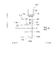
- FIG. 1 is a perspective view showing the overall configuration of a torque measuring device according to one embodiment of the present invention
- FIG. FIG. 4 is a schematic front view showing the arrangement of magnets of Hall sensors, Hall elements, TMR elements, and multipolar magnetic rings in the torque measuring device according to one embodiment of the present invention
- 1 is a schematic diagram showing the configuration of a multipolar magnetic ring used in a torque measuring device according to an embodiment of the invention
- FIG. 4 is a pulse waveform diagram showing A-phase, B-phase and Z-phase pulses detected by the torque measuring device according to the embodiment of the present invention
- Magnetic field strength (A) emitted by the multipolar magnetic ring of the torque measuring device according to one embodiment of the present invention, magnetic field strength (B) emitted by the magnet of the Hall sensor, and the multipolar magnetic ring and the Hall sensor 3 is a waveform diagram showing the relationship between the total strength of the magnetic fields emitted by the magnets and the threshold.
- FIG. 1 is a perspective view showing the overall configuration of a torque measuring device according to one embodiment of the invention.
- FIG. 2 is a schematic front view showing the arrangement of magnets of Hall sensors, Hall elements, TMR elements, and multipolar magnetic rings in a torque measuring device according to an embodiment of the present invention.
- FIG. 3 is a schematic diagram showing the configuration of a multipolar magnetic ring used in the torque measuring device according to one embodiment of the present invention;
- FIG. 4 is a pulse waveform diagram showing A-phase, B-phase and Z-phase pulses detected by the torque measuring device according to the embodiment of the present invention.
- FIG. 1 is a perspective view showing the overall configuration of a torque measuring device according to one embodiment of the invention.
- FIG. 2 is a schematic front view showing the arrangement of magnets of Hall sensors, Hall elements, TMR elements, and multipolar magnetic rings in a torque measuring device according to an embodiment of the present invention.
- FIG. 3 is a schematic diagram showing the configuration of a multipolar magnetic ring used in the torque measuring device
- FIG. 5 shows the strength (A) of the magnetic field emitted by the multipolar magnetic ring of the torque measuring device according to one embodiment of the present invention, the strength (B) of the magnetic field emitted by the magnet of the Hall sensor, and the multipolar magnetic
- FIG. 4 is a waveform chart showing the relationship between the total strength of the magnetic field emitted by the magnets of the ring and the Hall sensor and the threshold.
- the direction in which the axis X of the torque measuring device 100 extends will be referred to as the rotation axis X direction or the axis X direction.
- the direction of arrow a in the direction of the rotation axis X is the drive side or left side
- the direction of arrow b is the driven side or right side.
- the direction of arrow c moving away from the axis X is defined as the outer peripheral side
- the direction of arrow d approaching the axis X is defined as the inner peripheral side.
- the upper side (the direction of arrow e) and the lower side (the direction of arrow f) in the torque measuring device 100 mean the vertical relationship of the torque measuring device 100 in the gravitational direction on the drawing.
- the torque measuring device 100 includes a driving side flange 110, a driven side flange 120, and a predetermined wall thickness and a predetermined outer diameter between the driving side flange 110 and the driven side flange 120. and a hollow cylindrical strain body 130 having a However, in FIG. 1 , the strain body 130 is hidden between the driving side flange 110 and the driven side flange 120 .
- the drive-side flange 110 is a disk-shaped member.
- the drive-side flange 110 is provided with a plurality of screw holes 112 at equal intervals on a concentric circle in a state of penetrating the drive-side flange 110 .
- an end surface 110s on the left side (arrow a direction) of the drive-side flange 110 in the figure is connected to a measuring roller, a dynamometer, a brake mechanism, etc. of a chassis dynamo rotated by the wheels of an automobile, for example.
- a drive-side connecting member (not shown) is connected through a plurality of screw holes 112 .
- the drive-side flange 110 has its peripheral side surface covered by a cover body 152 having an annular half-split structure provided on the fixed base 150 .
- the cover body 152 does not cover the end surface 110s of the drive-side flange 110, but exposes it.
- the cover body 152 is fixed to the fixed base 150 by screws (not shown) or the like.
- the driven side flange 120 is a disc-shaped member having the same outer diameter as the driving side flange 110 .
- the drive-side flange 110 and the driven-side flange 120 are integrally formed via a strain-generating body 130 provided therebetween. That is, the driving side flange 110, the strain generating body 130, and the driven side flange 120 are integrated with the axis X as the center.
- the driven side flange 120 is not covered with the cover body 152 and is entirely exposed above the fixed base 150 (in the direction of arrow e).
- a plurality of screw holes 122 are provided at equal intervals on a concentric circle while passing through the driven side flange 120.
- a driven flange 120 is coupled to a load member (not shown) through a plurality of threaded holes 122 .
- the driven-side flange 120 has a plurality of bottomed holes (hereinafter simply referred to as “holes”) at regular intervals with respect to a circumferential side surface (hereinafter referred to as "peripheral side surface") 120a. 124 are formed. Light-emitting elements (not shown) such as light-emitting diodes constituting optical sensors (not shown) are embedded in the plurality of holes 124 in the driven side flange 120 .
- a detection unit 300 as a magnetic field detection device is attached at a predetermined position of the fixed base 150 facing the peripheral side surface 120a of the driven side flange 120 having the hole 124 in which the light emitting element of the optical sensor is embedded.
- the detection unit 300 is provided with a light-receiving element such as a photodiode that receives light output from the light-emitting element of the optical sensor described above.
- This optical sensor transmits a signal detected by a later-described strain gauge attached to the strain-generating body 130 between the light-emitting element of the driven-side flange 120 and the light-receiving element of the detection unit 300 without contact.
- a magnet 161 constituting a hall sensor 160 is embedded in one of the plurality of holes 124 provided in the peripheral side surface 120a of the driven side flange 120 together with the light emitting element (not shown) of the optical sensor described above. there is That is, any one of the plurality of holes 124 of the driven side flange 120 is shared by both the light emitting element and the magnet 161 of the hall sensor 160 .
- the magnet 161 of the Hall sensor 160 is provided at a mechanical origin for outputting a Z-phase signal when the driven-side flange 120 makes one rotation (one round) by a Hall element 162, which will be described later. .
- This is for detecting the rotating position of a rotating shaft (not shown) such as a shaft as a load member connected to the driven side flange 120 in the torque measuring device 100 .
- This Hall sensor 160 is configured in a non-contact manner by a magnet 161 provided on the driven side flange 120 and a Hall element 162 provided on the detection unit 300 .
- the Hall sensor 160 is a magnetic sensor that uses the Hall effect to convert a first magnetic field generated by a magnet 161 or a first magnetic field generated by a current into an electric signal by a Hall element 162 as a first detection element and outputs the electric signal.
- an annular multipolar magnetic ring having substantially the same outer diameter as the driven side flange 120 with respect to the end face 120b on the right side (in the direction of the arrow b) in which a plurality of screw holes 122 are formed. 140 are integrally attached.
- the multipolar magnetic ring 140 rotates simultaneously with the driving side flange 110 and the driven side flange 120 .
- the outer diameter of the multipolar magnetic ring 140 may be larger or smaller than the outer diameter of the driven side flange 120 .
- the multipolar magnetic ring 140 is a thin plate and annular ring member, and is a plastic magnetic ring that is lightened so as not to load the integrally attached driven side flange 120 during high-speed rotation.
- the multipolar magnetic ring 140 is an axial type consisting of a total of 16 poles (groups) in which a plurality of pairs of S poles and N poles are magnetized at equal intervals along the circumferential direction along the end face 140s. is a magnetic ring.
- the multipolar magnetic ring 140 need not be limited to 16 poles, and may have 8 poles, 24 poles, or more. good.
- the strain-generating body 130 is a hollow cylindrical member located between the drive-side flange 110 and the driven-side flange 120 and integrally formed therewith.
- a plurality of strain gauges (not shown) are attached to the inner peripheral surface of the strain generating body 130 .
- a plurality of strain gauges are connected to form a Wheatstone bridge circuit.
- the driving side flange 110, the driven side flange 120, and the strain generating body 130 formed therebetween it is necessary for the driving side flange 110, the driven side flange 120, and the strain generating body 130 formed therebetween to receive electric power from the outside when measuring the amount of torque. . Therefore, in the torque measuring device 100, electric power is transmitted from the outside in a non-contact manner, for example, in a rotary transformer format.
- the detection unit 300 is arranged so as to face the peripheral side surface 120 a of the driven side flange 120 .
- a Hall element 162 is attached at a position facing the magnet 161 of the Hall sensor 160 embedded in the hole 124 of the peripheral side surface 120 a of the driven side flange 120 .
- the light receiving element of the optical sensor and the Hall element 162 of the Hall sensor 160 are attached to the circuit board 180 of the detection unit 300 .
- the detection unit 300 includes a TMR (Tunneling Magneto Resistance) element 170 as a second detection element that detects the magnetic field (second magnetic field) of the multipolar magnetic ring 140 and outputs an A-phase signal and a B-phase signal. is mounted on the circuit board 180 at a position facing the multi-pole magnetic ring 140 .
- TMR Transmission Magneto Resistance
- the TMR element 170 is a tunnel magnetoresistive element that utilizes the tunnel magnetoresistive effect.
- the direction of the magnetic field acting on the TMR element 170 rotates according to the rotation, and the A-phase signal and the B-phase signal which are out of phase with each other are output. do.
- the B-phase signal is out of phase with the A-phase signal output from the TMR element 170 by 90 degrees.
- the A-phase signal is output with a phase lead of the B-phase signal by 90 degrees
- the driven-side flange 120 rotates counterclockwise
- the A-phase signal is output.
- the signal is output with a phase delay of 90 degrees from the B-phase signal.
- the Hall element 162 of the Hall sensor 160 detects the magnetic field of the magnet 161 when it faces the magnet 161 when the driven-side flange 120 rotates, and outputs a Z-phase signal to the driven-side flange 120 one rotation (1 output once per cycle).
- the position (polarity) of the magnet 161 embedded in the hole 124 of the peripheral side surface 120a of the driven side flange 120 and the multipolar magnetic ring 140 must be aligned.
- the driven side flange 120 and the multipolar magnetic ring 140 are integrally attached so that the magnetic field peak of the south pole of the magnet 161 and the magnetic field peak of the south pole of the multipolar magnetic ring 140 are aligned.
- an end surface 140s (FIG. 2) facing the driven side flange 120 has a columnar protrusion protruding leftward (in the direction of arrow a) at an arbitrary position.
- 142 (FIG. 3) are formed.
- an end face 120b on the side facing the multipolar magnetic ring 140 is formed with a recess 123 which is a cylindrical hole into which the protrusion 142 described above is fitted.
- the S pole magnetic field peak of the magnet 161 of the Hall element 162 and the multipolar magnetic ring 140 is set in advance so that the peak of the magnetic field of the S pole of .
- the magnet 161 of the Hall element 162 and the S pole of the multipolar magnetic ring 140 are arranged adjacent to each other in the X-axis direction of the driven flange 120 .
- the driven side flange 120, the magnet 161, and the multipolar magnetic ring 140 constitute a magnetic field generating device for the torque measuring device.
- the TMR element 170 not only the TMR element 170 but also a DMR (Double Magneto Resistance) element, a GMR (Giant Magneto Resistive effect) element, an AMR (Anisotropic Magneto Resistive) element, or the like is used as long as it is a magnetoresistive effect element. You may do so.
- the TMR element 170 is also attached to the circuit board of the detection unit 300 .
- an arithmetic processing section mounted on the circuit board 180 of the detection unit 300 is driven based on the number of pulses per unit time. The number of rotations or rotational speed (rpm) of the side flange 120 can be determined.
- the phase of the A-phase signal or the B-phase signal output from the TMR element 170 advances in accordance with the rotational direction of the driven flange 120. , or will be late. Therefore, the arithmetic processing unit of the circuit board 180 can also determine the rotation direction of the driven side flange 120 based on the phases of the A phase and the B phase output from the TMR element 170 .
- the Hall element 162 and the TMR element 170 are arranged in parallel at positions on the circuit board 180 facing the magnet 161 of the driven side flange 120 and the multipolar magnetic ring 140, respectively.
- This detection unit 300 serves as a magnetic field detection device for a torque measuring device.
- the Hall element 162 of the Hall sensor 160 and the TMR element 170 that detects the magnetic field of the multipolar magnetic ring 140 are provided in parallel at positions close to each other. Therefore, in the detection unit 300, compared with the case where the Hall element 162 and the TMR element 170 are provided at positions far apart from each other, it is possible to contribute to space saving and downsizing.
- both the Hall element 162 and the TMR element 170 are mounted on the circuit board 180 of the detection unit 300 at close positions.
- the Hall element 162 and the TMR element 170 are arranged at a constant distance along the axis X direction so as not to exert too much influence.
- the Hall element 162 of the Hall sensor 160 detects the magnetic field in the radial direction of the magnet 161 embedded in the hole 124 of the peripheral side surface 120 a of the driven flange 120 .
- the TMR element 170 detects the magnetic field in the axial direction in the multipolar magnetic ring 140 . In other words, the Hall element 162 and the TMR element 170 have different magnetic field detection directions.
- the strength of the magnetic field corresponding to the A phase and B phase is, for example, 2.0 mT (millitesla).
- the strength of the magnetic field corresponding to the Z phase when only the magnetic field of the magnet 161 of the Hall sensor 160 is detected by the Hall element 162 is 1.5 mT.
- the Hall element 162 has the strength of the magnetic field of the magnet 161 (1.5 mT) and the strength of the magnetic field of the multipolar magnetic ring 140 (2.0 mT). will detect a applied 3.5 mT magnetic field.
- the Hall element 162 is configured to output a Z-phase signal when the intensity of the detected magnetic field exceeds 3.0 mT set as a threshold. That is, even if the Hall element 162 is affected by the magnetic field of the multipolar magnetic ring 140 when detecting the magnetic field of the magnet 161, the Hall element 162 detects the magnetic field from the multipolar magnetic ring 140 when the magnetic field of the magnet 161 is not detected. Since a magnetic field of 2.0 mT or more is never detected, the threshold value of 3.0 mT is not exceeded and the Z-phase signal is never output.
- the peak of the magnetic field of the S pole of the magnet 161 and the peak of the magnetic field of the S pole of the multipolar magnetic ring 140 coincide with each other.
- the timing when 170 detects only the magnetic field of multipolar magnetic ring 140 it is not affected by the magnetic field of magnet 161, so it outputs only the A-phase and B-phase signals.
- the TMR element 170 that detects the magnetic field of the multipolar magnetic ring 140 outputs Based on the A-phase and B-phase signals, the rotation speed and rotation direction of the driven flange 120 can be accurately calculated.
- the Hall element 162 can reliably detect the Z-phase signal.
- the strong magnetic field of the magnet 161 may adversely affect the magnetic field of the multipolar magnetic ring 140, causing the TMR element 170 to malfunction. Therefore, in the torque measuring device 100, it is necessary to set the magnetic field of the magnet 161 of the hall sensor 160 so as not to be too strong.
- the Hall element 162 detects the strength of the magnetic field of the magnet 161 (0.5 mT) and the strength of the magnetic field of the multipolar magnetic ring 140 (2.0 mT) superimposed.
- the magnetic field strength is 2.5 mT and does not exceed the threshold value of 3.0 mT.
- the Hall element 162 detects the strength of the magnetic field of the multipolar magnetic ring 140 even when the magnetic field of the magnet 161 is not detected. (2.0 mT), the Z-phase signal may be output.
- an appropriate Along with setting the strength and distance of the magnetic field, it is important to set a threshold at which the Hall element 162 does not malfunction.
- the torque measuring device 100 since the torque measuring device 100 has the configuration in which the driven side flange 120 and the multipolar magnetic ring 140 are integrally attached, compared to the case where the multipolar magnetic ring 140 is provided separately from the driven side flange 120, It can be made smaller and more compact.
- the torque measuring device 100 includes a Hall element 162 arranged to face a magnet 161 attached to a hole 124 of a peripheral side surface 120a of a driven flange 120, and a TMR element 170 arranged to face a multipolar magnetic ring 140. It is provided in parallel with the circuit board 180 of the detection unit 300 . Therefore, the torque measuring device 100 can be made small and compact as a whole without increasing the size of the detection unit 300 as well.
- the Hall element 162 and the TMR element 170 are arranged on the circuit board 180 at positions close to each other. detects the magnetic field of the magnet 161 .
- the maximum magnetic field strength of the magnet 161 is 1.5 mT and the maximum magnetic field strength of the multipolar magnetic ring 140 is 2.0 mT.
- the total is 3.5 mT, which is the sum of the magnetic force vectors according to the principle of superposition.
- the Hall element 162 is set to 3.0 mT as a threshold for reliably outputting the Z-phase signal without error when 3.5 mT is detected as a reference for outputting the Z-phase signal, in anticipation of safety. .
- the Hall element 162 can output a Z-phase signal only when the magnetic field of the multipolar magnetic ring 140 and the magnetic field of the magnet 161 are detected at the same time.
- the arithmetic processing circuit provided on the circuit board 180 of the detection unit 300 can also calculate the rotational position of the driven side flange 120 based on the Z-phase signal.
- the arithmetic processing circuit provided on the circuit board 180 of the detection unit 300 can also accurately determine the rotation speed and rotation direction of the driven side flange 120 .
- the torque measuring device 100 that is much smaller than the conventional one, and the rotational position of the driven side flange 120 as well as the rotational speed and rotational direction of the driven side flange 120 can be obtained. be able to.
- the torque measuring device of the present invention is not limited to the configurations of the above embodiments.
- those skilled in the art can appropriately modify the torque measuring device of the present invention according to conventionally known knowledge. As long as the configuration of the present invention is still provided even with such modification, it is, of course, included in the scope of the present invention.
- SYMBOLS 100... Torque measuring apparatus 110... Drive side flange 120... Driven side flange 130... Strain-generating body 140... Multipolar magnetic ring 150... Fixed base 160... Hall sensor 161... Magnet 162... Hall element, 170...TMR element, 180...circuit board, 300...detection unit.
Landscapes
- Physics & Mathematics (AREA)
- General Physics & Mathematics (AREA)
- Transmission And Conversion Of Sensor Element Output (AREA)
- Power Steering Mechanism (AREA)
Abstract
従来に比して一段と小型化し得るトルク測定装置を提供する。 本発明のトルク測定装置(100)は、駆動側フランジ(110)と、従動側フランジ(120)と、駆動側フランジ(110)と従動側フランジ(120)との間に一体に設けられた起歪体(130)と、従動側フランジ(120)における外周側の周側面の所定位置に設けられた磁石(161)と、従動側フランジ(120)における円盤状の端面に一体に取り付けられた環状の多極磁気リング(140)と、従動側フランジ(120)の回転中に磁石(161)が発生する第1磁界を検出する第1検出素子(162)と、従動側フランジ(120)と共に回転する多極磁気リング(140)の回転中に発生する第2磁界を検出する第2検出素子(170)とを備える検出装置(300)とを備え、第1検出素子(162)は、第1磁界と、第2磁界との合計が所定の閾値を超えた場合に従動側フランジ(120)が1回転したことを表す信号を出力する。
Description
本発明は、トルク測定装置、トルク測定装置用の磁界発生装置、および、トルク測定装置用の磁界検出装置に関する。
従来、トルク測定装置においては、回転体と負荷との間の回転軸に設けられ、回転体と負荷との間の回転トルクを非接触によって測定するものである。例えば、自動車のエンジンの動力を車輪に伝達する役目を持っているドライブシャフトにおいて、その軸トルクを測定する軸トルク測定装置が提案されている(例えば、特許文献1参照。)。
この軸トルク測定装置においては、リング状の磁気エンコーダの周囲に対向するように配置されたホール素子等の2つの磁気センサによって検出するA相、B相の信号により回転方向を判別し、A相およびB相の双方の信号の差分からドライブシャフトのねじれの方向およびねじれ量を測定し、そのねじれ量から軸トルクを算出している。
しかしながら、特許文献1の軸トルク測定装置においては、A相、B相の信号から回転速度や回転角度を検出するために、角センサターゲットとセンサ側ユニットとからなる回転検出機を2つ用いる構成である。このような軸トルク測定装置においては、回転検出機を2つ用いる構成であるため全体として大型化し易く、従来から更に小型化したいという要望があった。
本発明は、以上の背景に鑑みてなされたものであり、従来に比して一段と小型化し得るトルク測定装置を提供することを目的とする。
上記課題は、以下の本発明により解決される。即ち、本発明のトルク測定装置は、駆動側フランジと、従動側フランジと、前記駆動側フランジと前記従動側フランジとの間であって、前記駆動側フランジおよび前記従動側フランジの双方と同一の軸線上において一体に設けられ、ひずみゲージが取り付けられた起歪体と、前記従動側フランジにおける外周側の周側面の所定位置に設けられた磁石と、前記従動側フランジにおける円盤状の端面に一体に取り付けられた環状の多極磁気リングと、前記従動側フランジの回転中に前記磁石が発生する第1磁界を検出する第1検出素子と、前記従動側フランジと共に回転する前記多極磁気リングの回転中に当該多極磁気リングが発生する第2磁界を検出する第2検出素子とを備える検出装置とを備え、前記第1検出素子は、前記第1磁界と、前記第2磁界との合計が所定の閾値を超えた場合に前記従動側フランジが1回転したことを表す信号を出力する。
本発明のトルク測定装置用の磁界発生装置は、駆動側フランジと、従動側フランジと、前記駆動側フランジと前記従動側フランジとの間であって、前記駆動側フランジおよび前記従動側フランジの双方と同一の軸線上において一体に設けられた起歪体と、検出装置と対向して配置され、前記従動側フランジにおける外周側の周側面の所定位置に設けられて磁界を発生する磁石と、前記従動側フランジにおける円盤状の端面に一体に取り付けられて磁界を発生する環状の多極磁気リングと、を備える。
本発明のトルク測定装置用の磁界検出装置は、従動側フランジの回転中に磁石が発生する磁界を検出する第1検出素子と、前記従動側フランジと共に回転する多極磁気リングの回転中に当該多極磁気リングが発生する磁界を検出する第2検出素子とを備え、前記第1検出素子は、前記磁石が発生する磁界と、前記多極磁気リングが発生する磁界との合計が所定の閾値を超えた場合に前記従動側フランジが1回転したことを表す信号を出力する。
<実施の形態>
続いて、本発明の実施の形態について図面を参照しながら説明する。図1は、本発明の一実施の形態にかかるトルク測定装置の全体構成を示す斜視図である。図2は、本発明の一実施の形態にかかるトルク測定装置におけるホールセンサの磁石、ホール素子、TMR素子および多極磁気リングの配置を示す略線的正面図である。図3は、本発明の一実施の形態にかかるトルク測定装置に用いられる多極磁気リングの構成を示す略線図である。図4は、本発明の一実施の形態にかかるトルク測定装置によって検出されるA相、B相およびZ相のパルスを示すパルス波形図である。図5は、本発明の一実施の形態にかかるトルク測定装置の多極磁気リングの発する磁界の強さ(A)、ホールセンサの磁石の発する磁界の強さ(B)、および、多極磁気リングとホールセンサの磁石の発する磁界の強さの合計と閾値との関係をそれぞれ示す波形図である。
続いて、本発明の実施の形態について図面を参照しながら説明する。図1は、本発明の一実施の形態にかかるトルク測定装置の全体構成を示す斜視図である。図2は、本発明の一実施の形態にかかるトルク測定装置におけるホールセンサの磁石、ホール素子、TMR素子および多極磁気リングの配置を示す略線的正面図である。図3は、本発明の一実施の形態にかかるトルク測定装置に用いられる多極磁気リングの構成を示す略線図である。図4は、本発明の一実施の形態にかかるトルク測定装置によって検出されるA相、B相およびZ相のパルスを示すパルス波形図である。図5は、本発明の一実施の形態にかかるトルク測定装置の多極磁気リングの発する磁界の強さ(A)、ホールセンサの磁石の発する磁界の強さ(B)、および、多極磁気リングとホールセンサの磁石の発する磁界の強さの合計と閾値との関係をそれぞれ示す波形図である。
なお、本実施の形態の説明において、以下の説明では、便宜上、トルク測定装置100の軸線Xが延びる方向を回転軸X方向または軸線X方向とする。また、以下の説明では、便宜上、回転軸X方向において矢印a方向を駆動側または左側、矢印b方向を従動側または右側とする。軸線Xに垂直な径方向において、軸線Xから遠ざかる矢印c方向を外周側とし、軸線Xに近づく矢印d方向を内周側とする。さらに、トルク測定装置100において上側(矢印e方向)および下側(矢印f方向)は、図面上におけるトルク測定装置100の重力方向における上下関係を意味する。
図1および図2に示すように、トルク測定装置100は、駆動側フランジ110と、従動側フランジ120と、駆動側フランジ110と従動側フランジ120との間に所定の肉厚および所定の外径を有する中空円筒状の起歪体130とを有している。ただし、図1においては、駆動側フランジ110と従動側フランジ120との間に起歪体130が隠れている状態である。
駆動側フランジ110は、円盤状の部材である。駆動側フランジ110は、当該駆動側フランジ110を貫通した状態で同心円上に等間隔で複数個のネジ穴112が設けられている。
駆動側フランジ110において、当該駆動側フランジ110の図中左側(矢印a方向)の端面110sには、例えば自動車の車輪によって回転させられるシャーシダイナモの測定ローラとダイナモメータ、ブレーキ機構等に連結される駆動側連結部材(図示せず)が複数個のネジ穴112を介して連結される。
また、駆動側フランジ110は、固定台150に設けられた環状の半割構造からなるカバー体152によって当該駆動側フランジ110の周側面が覆われている。なお、カバー体152は、駆動側フランジ110の端面110sを覆っておらず、露出させている。カバー体152は、固定台150に対して図示しないネジ等によって固定されている。
従動側フランジ120は、駆動側フランジ110と同一外径を有する円盤状の部材である。駆動側フランジ110および従動側フランジ120は、両者の間に設けられた起歪体130を介して一体に形成されている。すなわち駆動側フランジ110、起歪体130、および、従動側フランジ120は、軸線Xを中心として一体化されている。なお、従動側フランジ120は、駆動側フランジ110とは異なり、カバー体152に覆われてはおらず、固定台150の上側(矢印e方向)において全て露出された状態にある。
従動側フランジ120においても、当該従動側フランジ120を貫通した状態で同心円上に等間隔で複数個のネジ穴122が設けられている。従動側フランジ120は、負荷部材(図示せず)に対して複数個のネジ穴122を介して結合されている。
従動側フランジ120は、周方向の側面(以下、これを「周側面」という。)120aに対して一定の間隔毎に複数個の有底の穴(以下、これを単に「穴」という。)124が形成されている。従動側フランジ120における複数個の穴124の内部には、図示しない光センサを構成する発光ダイオード等の発光素子(図示せず)がそれぞれ埋め込まれている。
光センサの発光素子が埋め込まれた穴124を有する従動側フランジ120の周側面120aと対向する固定台150の所定の位置には、磁界検出装置としての検出ユニット300が取り付けられている。
検出ユニット300においては、上述した光センサの発光素子から出力された光を受光するフォトダイオード等の受光素子が設けられている。この光センサは、起歪体130に取り付けられた後述する歪ゲージによって検出された信号を従動側フランジ120の発光素子および検出ユニット300の受光素子間で非接触により伝送する。
従動側フランジ120における周側面120aに設けられた複数個の穴124の何れか一つには、ホールセンサ160を構成する磁石161が上述した光センサの発光素子(図示せず)と共に埋め込まれている。すなわち、従動側フランジ120の複数個の穴124の何れか一つは、発光素子およびホールセンサ160の磁石161の双方に共有されている。
ホールセンサ160の磁石161は、後述するホール素子162によって当該従動側フランジ120が1回転(1周)したときにZ相の信号として出力するための機械的な原点となる位置に設けられている。これは、トルク測定装置100において、従動側フランジ120に連結された負荷部材として例えばシャフト等の回転軸(図示せず)における回転中の位置を検出するためである。
このホールセンサ160は、従動側フランジ120に設けられた磁石161および検出ユニット300に設けられたホール素子162によって非接触に構成されている。ホールセンサ160は、ホール効果を利用して、磁石161が発する第1磁界や電流が発する第1磁界を第1検出素子としてのホール素子162により電気信号に変換して出力する磁気センサである。
また、従動側フランジ120においては、複数個のネジ穴122が形成されている右側(矢印b方向)の端面120bに対して当該従動側フランジ120とほぼ同一外径を有する環状の多極磁気リング140が一体に取り付けられている。
すなわち、従動側フランジ120と多極磁気リング140とは一体化された状態であるため、多極磁気リング140は、駆動側フランジ110および従動側フランジ120と同時に回転される。なお、多極磁気リング140の外径は、従動側フランジ120の外径よりも大きくても小さくてもよい。
多極磁気リング140は、薄板かつ円環状のリング部材からなり、一体に取り付けられた従動側フランジ120に対して高速回転時に負荷とならないよう軽量化されたプラスチック製の磁気リングである。
図3に示すように、多極磁気リング140は、その端面140sに周方向に沿って1組のS極およびN極が等間隔で複数着磁された合計16極(組)からなるアキシャルタイプの磁気リングである。なお、多極磁気リング140は、16極に限る必要はなく、8極、24極、または、それ以上の極数であってもよく、要求される回転分解能に合わせた極数を設定すればよい。
起歪体130は、駆動側フランジ110および従動側フランジ120の間に位置し、両者と一体に形成された中空円筒状の部材である。起歪体130の内周面には、複数のひずみゲージ(図示せず)が貼着されている。複数のひずみゲージはホイーストンブリッジ回路を形成するように結線される。
因みに、トルク測定装置100においては、駆動側フランジ110、従動側フランジ120、および、これらの間に形成された起歪体130がトルク量を測定する際に必要な電力を外部から受け取る必要がある。そのためトルク測定装置100においては例えばロータリートランス形式により外部から非接触で電力伝送が行われる。
ところでトルク測定装置100においては、検出ユニット300が従動側フランジ120の周側面120aと対向するように配置されている。検出ユニット300においては、従動側フランジ120の周側面120aの穴124に埋め込まれたホールセンサ160の磁石161と対向する位置にホール素子162が取り付けられている。実際上、光センサの受光素子やホールセンサ160のホール素子162は、検出ユニット300の回路基板180に対して取り付けられている。
さらに検出ユニット300には、多極磁気リング140の磁場(第2磁界)を検出し、A相の信号およびB相の信号を出力する第2検出素子としてのTMR(Tunneling Magneto Resistance)素子170についても多極磁気リング140と対向する回路基板180の位置に取り付けられている。
TMR素子170は、トンネル磁気抵抗効果を利用したトンネル磁気抵抗効果素子である。実際、多極磁気リング140が従動側フランジ120と共に回転すると、その回転に応じてTMR素子170に作用する磁界の向きが回転し、互いに位相がずれたA相の信号およびB相の信号を出力する。
実際、図4に示すように、TMR素子170が出力するA相の信号に対してB相の信号は位相が90度ずれている。例えば、従動側フランジ120が時計回り方向へ回転するとA相の信号がB相の信号よりも位相が90度進んだ状態で出力され、従動側フランジ120が反時計回り方向へ回転するとA相の信号がB相の信号よりも位相が90度遅れた状態で出力される。
ところで、ホールセンサ160のホール素子162は、従動側フランジ120が回転したときに磁石161と対向した場合に当該磁石161の磁界を検出し、Z相の信号を従動側フランジ120の1回転(1周)につき1回出力する。
なお、従動側フランジ120の周側面120aの穴124に埋め込まれた磁石161と、多極磁気リング140の位置(極性)とを合わせておく必要がある。例えば、磁石161におけるS極の磁界のピークと、多極磁気リング140のS極の磁界のピークとが一致するように従動側フランジ120と多極磁気リング140とが一体に取り付けられている。
具体的には、多極磁気リング140のうち、従動側フランジ120と向かい合う側の端面140s(図2)の任意の位置には、左側(矢印a方向)に突出した円柱状の突出した凸部142(図3)が形成されている。また、従動側フランジ120のうち、多極磁気リング140と向かい合う側の端面120bには、上述した凸部142と嵌合される円柱状の穴である凹部123が形成されている。
したがって、多極磁気リング140の凸部142と、従動側フランジ120の凹部123とが嵌合された状態においては、ホール素子162の磁石161におけるS極の磁界のピークと、多極磁気リング140のS極の磁界のピークとが一致するように予め設定されている。例えば、図2に示すように、従動側フランジ120の軸線X方向において、ホール素子162の磁石161と多極磁気リング140のS極とは互いに隣接するように配置されている。なお、トルク測定装置100においては、従動側フランジ120、磁石161、多極磁気リング140によってトルク測定装置用の磁界発生装置が構成されている。
なお、検出ユニット300においては、TMR素子170に限らず、磁気抵抗効果素子であれば、DMR(Double Magneto Resistance)素子、GMR(Giant Magneto Resistive effect)素子、AMR(Anisotropic Magneto Resistive)素子等を用いるようにしてもよい。因みに、TMR素子170についても検出ユニット300の回路基板に取り付けられている。
図3に示すように、TMR素子170は、多極磁気リング140の16極のうち、1組のS極からN極までの角度(この場合、22.5度(360÷16=22.5))に対して256パルス出力可能な素子である。
このため、図4に示すように、従動側フランジ120(多極磁気リング140)が1回転(1周)すると、ホール素子162からZ相の信号が1パルス出力されるのに対し、TMR素子170からはA相およびB相の信号として4096(256×16)パルスが出力される。
TMR素子170は、従動側フランジ120の1回転につき4096パルスを出力するので、検出ユニット300の回路基板180に搭載された演算処理部(図示せず)は単位時間当たりのパルス数に基づいて従動側フランジ120の回転数すなわち回転速度(rpm)を求めることができる。
また、図4に示すように、TMR素子170から出力されるA相の信号またはB相の信号は、従動側フランジ120の回転方向に応じてA相の信号またはB相の信号の位相が進み、または、遅れることになる。このため回路基板180の演算処理部では、TMR素子170から出力されるA相およびB相の位相に基づいて従動側フランジ120の回転方向についても判別することができる。
検出ユニット300においては、従動側フランジ120の磁石161および多極磁気リング140とそれぞれ対向する回路基板180の位置にホール素子162およびTMR素子170が並列した状態で配置されている。この検出ユニット300は、トルク測定装置用の磁界検出装置となる。
すなわち検出ユニット300では、ホールセンサ160のホール素子162および多極磁気リング140の磁界を検出するTMR素子170が互いに近接した位置に並列した状態で設けられている。このため検出ユニット300では、ホール素子162およびTMR素子170が互いに遠くに離れた位置に設けられた場合に比べて省スペース化に寄与し、小型化を図ることができる。
ところでトルク測定装置100においては、検出ユニット300の回路基板180上にホール素子162およびTMR素子170の双方を近接した位置に取り付けているが、磁石161の磁場および多極磁気リング140の磁場が互いに大きく影響し過ぎることのないようホール素子162およびTMR素子170が軸線X方向に沿って一定の距離を保って配置されている。
ホールセンサ160のホール素子162は、従動側フランジ120の周側面120aの穴124に埋め込まれた磁石161におけるラジアル方向の磁場を検出する。これに対してTMR素子170は、多極磁気リング140におけるアキシャル方向の磁場を検出する。すなわちホール素子162およびTMR素子170は、磁場を検出する方向がお互いに異なっている。
図5(A)に示すように、多極磁気リング140の磁界をTMR素子170によって検出したときのA相およびB相に対応する磁界の強さは例えば2.0mT(ミリテスラ)である。一方、図5(B)に示すように、ホールセンサ160の磁石161の磁界だけをホール素子162によって検出したときのZ相に対応する磁界の強さは、1.5mTである。
上述したように、従動側フランジ120の軸線X方向において、周側面120aの穴124に取り付けられた磁石161におけるS極の磁界のピークと、多極磁気リング140のS極の磁界のピークとが一致するように予め設定されている。このため、図5(C)に示すように、ホール素子162は、磁石161の磁界の強さ(1.5mT)と、多極磁気リング140の磁界の強さ(2.0mT)とが重畳された3.5mTの磁界を検出することになる。
ここで、ホール素子162は、検出した磁界の強さが閾値として設定された3.0mTを超えた場合にZ相の信号を出力するように構成されている。つまり、ホール素子162は、磁石161の磁界を検出する際、多極磁気リング140の磁界の影響を受けたとしても、磁石161の磁界を検出していないときは、多極磁気リング140からの2.0mT以上の磁界を検出することはないので、閾値3.0mTを超えることがなくZ相信号を出力してしまうことはない。
また、上述したように、従動側フランジ120の軸線X方向において、磁石161におけるS極の磁界のピークと、多極磁気リング140のS極の磁界のピークとが一致しているが、TMR素子170が多極磁気リング140の磁界だけを検出するタイミングでは、磁石161の磁界の影響を受けていないのでA相およびB相の信号だけを出力することになる。
この場合、検出ユニット300の回路基板180の演算処理部では、ホールセンサ160の磁石161による磁界の影響を受けることはないので、多極磁気リング140の磁界を検出するTMR素子170から出力されるA相およびB相の信号に基づいて従動側フランジ120の回転速度や回転方向について正確に算出することができる。
仮に、多極磁気リング140の磁界の強さを無視できる程度にホールセンサ160の磁石161の磁界が3.0mTよりも非常に強く大きい値を持つ場合、その磁石161の強い磁界に合わせて閾値を高く設定すれば、ホール素子162はZ相の信号を確実に検出することができる。
しかしながら、磁石161の強い磁界が多極磁気リング140の磁界に悪影響を及ぼしてTMR素子170が誤動作してしまう恐れが生じる。したがって、トルク測定装置100においては、ホールセンサ160の磁石161の磁界を強過ぎることのないように設定する必要がある。
また、ホールセンサ160の磁石161の磁界が1.5mTよりも非常に弱い場合、例えば多極磁気リング140の磁界の強さである2.0mTよりも低い例えば0.5mTの場合について考える。この場合、ホール素子162は、磁石161の磁界の強さ(0.5mT)と、多極磁気リング140の磁界の強さ(2.0mT)とが重畳されて検出してしまうが、合計の磁界の強さが2.5mTであり、閾値である3.0mTを超えなくなる。そのために、閾値を3.0mTから2.0mTに近い値まで下げた場合、ホール素子162は、磁石161の磁界を検出していないときであっても、多極磁気リング140の磁界の強さ(2.0mT)に基づいてZ相の信号を出力してしまうことにもなりかねない。
すなわち、ホールセンサ160の磁石161の磁界の強さ、多極磁気リング140の磁界の強さ、検出ユニット300におけるホール素子162とTMR素子170との間の距離等のパラメータに基づいて、適切な磁界の強さおよび距離を設定すると共に、ホール素子162が誤動作しない閾値を設定することが重要になる。
<作用および効果>
以上の構成において、トルク測定装置100では、従動側フランジ120および多極磁気リング140を一体に取り付けた構成であるため、従動側フランジ120と別体に多極磁気リング140を設ける場合に比べて小型化およびコンパクト化することができる。
以上の構成において、トルク測定装置100では、従動側フランジ120および多極磁気リング140を一体に取り付けた構成であるため、従動側フランジ120と別体に多極磁気リング140を設ける場合に比べて小型化およびコンパクト化することができる。
また、トルク測定装置100は、従動側フランジ120の周側面120aの穴124に取り付けられた磁石161と対向配置されたホール素子162、および、多極磁気リング140と対向配置されたTMR素子170が検出ユニット300の回路基板180に並列した状態で設けられている。このため、検出ユニット300としても大型化することなく、トルク測定装置100を全体的に小型コンパクト化することができる。
検出ユニット300では、回路基板180上にホール素子162およびTMR素子170が互いに近接した位置に配置されているため、ホール素子162が多極磁気リング140の磁界を検出してしまうと共に、TMR素子170が磁石161の磁界を検出してしまう。
しかしながら、検出ユニット300のホール素子162は、磁石161の磁界の強さが最大1.5mTであり、多極磁気リング140の磁界の強さの最大が2.0mTであるため、両者の磁界の合計は重ね合わせの原理により磁力ベクトルの総和である3.5mTとなる。またホール素子162はZ相の信号を出力する基準として、3.5mTを検出したときに誤りなく確実にZ相の信号を出力するための閾値として安全を見越した3.0mTと設定している。
これにより、ホール素子162は、多極磁気リング140の磁界を検出すると同時に磁石161の磁界を検出したときに限り、Z相の信号を出力することができる。かくして、検出ユニット300の回路基板180に設けられた演算処理回路では、Z相の信号に基づいて従動側フランジ120の回転位置についても算出することができる。
また、検出ユニット300のTMR素子170は、従動側フランジ120の磁石161が1個だけしか取り付けられていないため、多極磁気リング140の磁界を検出する際、磁石161の磁界を検出しない部分ではA相およびB相の信号を出力することができる。これにより、検出ユニット300の回路基板180に設けられた演算処理回路では、従動側フランジ120の回転速度および回転方向についても正確に求めることができる。
以上の構成によれば、従来に比して一段と小型化したトルク測定装置100を提供することができると共に、従動側フランジ120の回転速度および回転方向と共に、従動側フランジ120の回転位置についても求めることができる。
<他の実施の形態>
なお、本実施の形態のトルク測定装置100においては、アキシャルタイプの多極磁気リング140を用いるようにした場合について述べたが、本発明はこれに限らず、ラジアルタイプの多極磁気リングを用いるようにしてもよい。
なお、本実施の形態のトルク測定装置100においては、アキシャルタイプの多極磁気リング140を用いるようにした場合について述べたが、本発明はこれに限らず、ラジアルタイプの多極磁気リングを用いるようにしてもよい。
以上、本発明のトルク測定装置について、好ましい実施の形態を挙げて説明したが、本発明のトルク測定装置は上記実施の形態の構成に限定されるものではない。その他、当業者は、従来公知の知見に従い、本発明のトルク測定装置を適宜改変することができる。かかる改変によってもなお本発明の構成を具備する限り、勿論、本発明の範疇に含まれるものである。
100…トルク測定装置、110…駆動側フランジ、120…従動側フランジ、130…起歪体、140…多極磁気リング、150…固定台、160…ホールセンサ、161…磁石、162…ホール素子、170…TMR素子、180…回路基板、300…検出ユニット。
Claims (8)
- 駆動側フランジと、
従動側フランジと、
前記駆動側フランジと前記従動側フランジとの間であって、前記駆動側フランジおよび前記従動側フランジの双方と同一の軸線上において一体に設けられ、ひずみゲージが取り付けられた起歪体と、
前記従動側フランジにおける外周側の周側面の所定位置に設けられた磁石と、
前記従動側フランジにおける円盤状の端面に一体に取り付けられた環状の多極磁気リングと、
前記従動側フランジの回転中に前記磁石が発生する第1磁界を検出する第1検出素子と、前記従動側フランジと共に回転する前記多極磁気リングの回転中に当該多極磁気リングが発生する第2磁界を検出する第2検出素子とを備える検出装置と
を備え、
前記第1検出素子は、前記第1磁界と、前記第2磁界との合計が所定の閾値を超えた場合に前記従動側フランジが1回転したことを表す信号を出力する
トルク測定装置。 - 前記第1検出素子は前記磁石と対向するように配置され、前記第2検出素子は前記多極磁気リングと対向するように配置されている
請求項1に記載のトルク測定装置。 - 前記第1検出素子および前記第2検出素子は、前記検出装置において前記軸線に沿って並列した状態で配置されている
請求項2に記載のトルク測定装置。 - 前記第1磁界のピークと、前記第2磁界のピークとが一致するように前記従動側フランジと前記多極磁気リングとが一体に取り付けられている
請求項1に記載のトルク測定装置。 - 前記多極磁気リングが前記従動側フランジに取り付けられる端面には、位置決め用の凸部が形成され、
前記従動側フランジが前記多極磁気リングに取り付けられる端面には、前記凸部と係合される凹部が形成されている
請求項4に記載のトルク測定装置。 - 前記第1検出素子は、ホール素子であり、
前記第2検出素子は、TMR素子である
請求項1乃至5のいずれか一項に記載のトルク測定装置。 - 駆動側フランジと、
従動側フランジと、
前記駆動側フランジと前記従動側フランジとの間であって、前記駆動側フランジおよび前記従動側フランジの双方と同一の軸線上において一体に設けられた起歪体と、
検出装置と対向して配置され、前記従動側フランジにおける外周側の周側面の所定位置に設けられて磁界を発生する磁石と、
前記従動側フランジにおける円盤状の端面に一体に取り付けられて磁界を発生する環状の多極磁気リングと、
を備えるトルク測定装置用の磁界発生装置。 - 従動側フランジの回転中に磁石が発生する磁界を検出する第1検出素子と、
前記従動側フランジと共に回転する多極磁気リングの回転中に当該多極磁気リングが発生する磁界を検出する第2検出素子と
を備え、
前記第1検出素子は、前記磁石が発生する磁界と、前記多極磁気リングが発生する磁界との合計が所定の閾値を超えた場合に前記従動側フランジが1回転したことを表す信号を出力する
トルク測定装置用の磁界検出装置。
Priority Applications (1)
| Application Number | Priority Date | Filing Date | Title |
|---|---|---|---|
| CN202280059264.7A CN117897602A (zh) | 2021-07-12 | 2022-04-13 | 扭矩测定装置、扭矩测定装置用的磁场产生装置以及扭矩测定装置用的磁场检测装置 |
Applications Claiming Priority (2)
| Application Number | Priority Date | Filing Date | Title |
|---|---|---|---|
| JP2021115166A JP7709324B2 (ja) | 2021-07-12 | 2021-07-12 | トルク測定装置、トルク測定装置用の磁界発生装置、および、トルク測定装置用の磁界検出装置 |
| JP2021-115166 | 2021-07-12 |
Publications (1)
| Publication Number | Publication Date |
|---|---|
| WO2023286406A1 true WO2023286406A1 (ja) | 2023-01-19 |
Family
ID=84919169
Family Applications (1)
| Application Number | Title | Priority Date | Filing Date |
|---|---|---|---|
| PCT/JP2022/017711 Ceased WO2023286406A1 (ja) | 2021-07-12 | 2022-04-13 | トルク測定装置、トルク測定装置用の磁界発生装置、および、トルク測定装置用の磁界検出装置 |
Country Status (3)
| Country | Link |
|---|---|
| JP (2) | JP7709324B2 (ja) |
| CN (1) | CN117897602A (ja) |
| WO (1) | WO2023286406A1 (ja) |
Citations (5)
| Publication number | Priority date | Publication date | Assignee | Title |
|---|---|---|---|---|
| JPH11230838A (ja) * | 1998-02-17 | 1999-08-27 | Shinko Zoki Kk | トルクメータ |
| US20040015307A1 (en) * | 2000-08-22 | 2004-01-22 | David Heisenberg | Method for a phase angle correction during scanning of a code track |
| JP2009097895A (ja) * | 2007-10-15 | 2009-05-07 | Ntn Corp | ドライブシャフトの軸トルク測定装置および測定方法 |
| JP2018185198A (ja) * | 2017-04-25 | 2018-11-22 | 日本精工株式会社 | 角度検出装置、相対角度検出装置、トルクセンサ、電動パワーステアリング装置及び車両 |
| JP2021021586A (ja) * | 2019-07-25 | 2021-02-18 | ユニパルス株式会社 | トルク変換器 |
-
2021
- 2021-07-12 JP JP2021115166A patent/JP7709324B2/ja active Active
-
2022
- 2022-04-13 CN CN202280059264.7A patent/CN117897602A/zh active Pending
- 2022-04-13 WO PCT/JP2022/017711 patent/WO2023286406A1/ja not_active Ceased
-
2025
- 2025-05-01 JP JP2025076034A patent/JP2025105914A/ja active Pending
Patent Citations (5)
| Publication number | Priority date | Publication date | Assignee | Title |
|---|---|---|---|---|
| JPH11230838A (ja) * | 1998-02-17 | 1999-08-27 | Shinko Zoki Kk | トルクメータ |
| US20040015307A1 (en) * | 2000-08-22 | 2004-01-22 | David Heisenberg | Method for a phase angle correction during scanning of a code track |
| JP2009097895A (ja) * | 2007-10-15 | 2009-05-07 | Ntn Corp | ドライブシャフトの軸トルク測定装置および測定方法 |
| JP2018185198A (ja) * | 2017-04-25 | 2018-11-22 | 日本精工株式会社 | 角度検出装置、相対角度検出装置、トルクセンサ、電動パワーステアリング装置及び車両 |
| JP2021021586A (ja) * | 2019-07-25 | 2021-02-18 | ユニパルス株式会社 | トルク変換器 |
Also Published As
| Publication number | Publication date |
|---|---|
| CN117897602A (zh) | 2024-04-16 |
| JP7709324B2 (ja) | 2025-07-16 |
| JP2023011354A (ja) | 2023-01-24 |
| JP2025105914A (ja) | 2025-07-10 |
Similar Documents
| Publication | Publication Date | Title |
|---|---|---|
| JP5258884B2 (ja) | 磁気エンコーダおよびアクチュエータ | |
| JP5840374B2 (ja) | アブソリュートエンコーダ装置及びモータ | |
| JP5480967B2 (ja) | 多周期的絶対位置検出器 | |
| EP3112833B1 (en) | Systems and methods for measuring torque on rotating shaft | |
| JP6552637B2 (ja) | 回転角度を測定する装置および回転角度を測定する方法 | |
| US20060145688A1 (en) | Transducer of angular quantities for a cycle | |
| JP2018132360A5 (ja) | ||
| WO2013094042A1 (ja) | モータ、モータシステムおよびモータ用エンコーダ | |
| JP5564711B2 (ja) | 角度検知付き衝撃締付工具 | |
| JP7192110B2 (ja) | 回転角測定システム | |
| CN210922654U (zh) | 一种基于巨磁阻效应的磁电编码器 | |
| JP7709324B2 (ja) | トルク測定装置、トルク測定装置用の磁界発生装置、および、トルク測定装置用の磁界検出装置 | |
| TW202305325A (zh) | 運動檢測器 | |
| Kanno et al. | Linear and angular position sensing for twodegrees-of-freedom motor | |
| KR102706072B1 (ko) | 인덕티브 융합형 엔코더 | |
| US20230221147A1 (en) | Rotation angle detector | |
| JP2018105757A (ja) | 磁気エンコーダ装置 | |
| US11512980B2 (en) | Absolute position detection device and detection method of rotating body | |
| KR101271828B1 (ko) | 차량 조향각 감지 장치를 이용한 조향각 산출 방법 | |
| JP2006322794A (ja) | 操舵角センサ | |
| US11639860B2 (en) | Absolute position detection device and detection method of rotating body using magnetic material | |
| JP7573973B2 (ja) | 回転部材の少なくとも1つの回転パラメータを決定するシステム | |
| JP4161248B2 (ja) | 複合形検出器 | |
| JP4343585B2 (ja) | 絶対角度センサ付軸受装置およびその使用方法 | |
| JP7755759B2 (ja) | 磁石式回転角度センサシステム |
Legal Events
| Date | Code | Title | Description |
|---|---|---|---|
| 121 | Ep: the epo has been informed by wipo that ep was designated in this application |
Ref document number: 22841754 Country of ref document: EP Kind code of ref document: A1 |
|
| NENP | Non-entry into the national phase |
Ref country code: DE |
|
| WWE | Wipo information: entry into national phase |
Ref document number: 202280059264.7 Country of ref document: CN |
|
| 122 | Ep: pct application non-entry in european phase |
Ref document number: 22841754 Country of ref document: EP Kind code of ref document: A1 |