WO2023286205A1 - 筐体 - Google Patents
筐体 Download PDFInfo
- Publication number
- WO2023286205A1 WO2023286205A1 PCT/JP2021/026470 JP2021026470W WO2023286205A1 WO 2023286205 A1 WO2023286205 A1 WO 2023286205A1 JP 2021026470 W JP2021026470 W JP 2021026470W WO 2023286205 A1 WO2023286205 A1 WO 2023286205A1
- Authority
- WO
- WIPO (PCT)
- Prior art keywords
- lattice structure
- housing
- coolant
- passage
- refrigerant
- Prior art date
- Legal status (The legal status is an assumption and is not a legal conclusion. Google has not performed a legal analysis and makes no representation as to the accuracy of the status listed.)
- Ceased
Links
Images






Classifications
-
- H—ELECTRICITY
- H02—GENERATION; CONVERSION OR DISTRIBUTION OF ELECTRIC POWER
- H02K—DYNAMO-ELECTRIC MACHINES
- H02K5/00—Casings; Enclosures; Supports
- H02K5/04—Casings or enclosures characterised by the shape, form or construction thereof
- H02K5/20—Casings or enclosures characterised by the shape, form or construction thereof with channels or ducts for flow of cooling medium
-
- H—ELECTRICITY
- H05—ELECTRIC TECHNIQUES NOT OTHERWISE PROVIDED FOR
- H05K—PRINTED CIRCUITS; CASINGS OR CONSTRUCTIONAL DETAILS OF ELECTRIC APPARATUS; MANUFACTURE OF ASSEMBLAGES OF ELECTRICAL COMPONENTS
- H05K7/00—Constructional details common to different types of electric apparatus
- H05K7/20—Modifications to facilitate cooling, ventilating, or heating
Definitions
- the present invention relates to a housing, particularly a housing that houses contents including a heat source.
- the housing that houses the content including the heat source has a housing wall that forms a housing space that houses the content including the heat source.
- an elongated coolant passage may be formed between the outer surface and the inner surface of the housing wall.
- the heat generated by the heat source is radiated to the outside through the refrigerant flowing through the refrigerant passage.
- An elongated refrigerant passage is a refrigerant passage formed so that the maximum width of the refrigerant passage in a cross section across the refrigerant flow direction is shorter than the length of the refrigerant passage in the refrigerant flow direction.
- a housing that houses a motor (heat source) has a housing wall portion in which an elongated refrigerant passage is formed.
- the housing wall portion of Patent Documents 1 and 2 includes an inner cylinder and an outer cylinder that hold the stator of the motor.
- a coolant passage is formed between the inner cylinder and the outer cylinder.
- the refrigerant passage is devised to improve the cooling efficiency. Specifically, in Patent Documents 1 and 2, a plurality of narrowed portions (concave portions) are provided so that the cross-sectional area of the refrigerant passage is partially reduced.
- a plurality of fins connected to at least the inner cylinder are provided inside the refrigerant passage of Patent Document 1.
- the refrigerant passage of Patent Document 2 is provided with a plurality of cylinders that connect the inner cylinder and the outer cylinder.
- Patent Literature 1 the efficiency of heat exchange is improved by generating turbulence in the refrigerant flow by the restrictor and bringing the turbulent coolant flow into contact with fins provided downstream of the restrictor.
- Patent Literature 2 the efficiency of heat exchange is improved by generating turbulence in the refrigerant flow by means of the throttle portion and the cylinder to eliminate the stagnation of the refrigerant.
- cooling structure of the housing there are cases where a plurality of heat radiation fins are provided on the surface of the housing wall portion, as in Patent Document 3, for example.
- the heat generated by the heat source is radiated to the outside of the housing through the radiation fins.
- JP-A-08-198 JP 2010-041835 A Japanese Patent Application Laid-Open No. 2021-072758
- the housing that contains the contents, including the heat source is required to improve cooling performance while suppressing the increase in size.
- a housing that accommodates contents including a heat source is required to increase the degree of freedom in designing the shape of the housing while ensuring the cooling performance of the housing.
- the present invention can improve the cooling performance of the housing while suppressing an increase in the size of the housing, or can improve the degree of freedom in designing the shape of the housing while ensuring the cooling performance of the housing. , is intended to provide a housing.
- a housing that houses contents including a heat source has a problem that the shape of the outer surface and inner surface of the housing is restricted for the following two reasons.
- the first reason is that it is necessary to consider the shape of the contents and the interference with surrounding parts when mounting the housing.
- the second reason is that it is necessary to secure the rigidity and strength necessary to support the contents and the housing itself.
- the housing has a cooling structure, the following problems still exist. For a case that is restricted by the shape of the outer and inner surfaces of the case, it is necessary to improve the cooling performance while suppressing an increase in the size of the case, or to improve the design freedom of the case shape while ensuring the cooling performance. is required.
- the cooling structure By increasing the cooling performance of the cooling structure provided on the surface of the housing wall, the cooling structure can be made smaller, and there is room for making the case smaller than when fins are provided on the surface of the housing wall. Further, since the fins are thin plates, even if a plurality of fins are provided on the surface of the housing wall, they do not contribute much to improving the rigidity and strength of the housing itself. Therefore, there is room for reducing the size of the housing by increasing the rigidity and strength of the cooling structure provided on the surface of the housing wall. In this way, even if the shape of the outer surface and the inner surface of the housing is restricted, the cooling performance is improved while suppressing the enlargement of the housing, or the cooling performance is secured while the housing shape is designed freely. There is a need for a cooling structure that can improve
- a housing of one embodiment of the present invention has the following configuration.
- a housing having a housing wall forming a housing space for housing contents including a heat source,
- a cooling structure that includes a lattice structure in which a plurality of unit cells are arranged in three directions, that is, two directions that intersect with each other and a direction that intersects the plane including these two directions, and radiates heat generated by the heat source to the outside,
- a plurality of unit cells constituting the lattice structure are formed in a plurality of cell spaces of a convex polyhedron having the same number of vertices, the same number of faces, and the same number of sides, each cell space shares a surface and a plurality of sides forming the surface with the adjacent cell space;
- the plurality of unit cells forming the lattice structure includes at least one type of unit cell that is periodically repeated;
- Each of the plurality of unit cells constituting the lattice structure has at least one of a rod-shaped portion that is not parallel to all sides of
- Configuration 1 The housing wall forms a coolant passage through which the coolant flows between the outer surface and the inner surface of the housing wall,
- the refrigerant passage is formed such that the maximum width of the refrigerant passage in a cross section transverse to the refrigerant flow direction is shorter than the length of the refrigerant passage in the refrigerant flow direction
- the housing has the cooling structure in which the heat generated by the heat source is radiated to the outside through the refrigerant flowing in the refrigerant passage,
- the housing wall portion forming the refrigerant passage and the lattice structure portion are formed so as to be continuous,
- the coolant passage has a passage portion provided with the lattice structure and a passage portion not provided with the lattice structure in the cross section passing through the lattice structure,
- Configuration 2 The outer surface or inner surface of the housing wall portion and the lattice structure portion are formed so as to be continuous, and the lattice structure portion of the housing wall portion is provided in the lattice structure portion. The ends of the lattice structure are exposed to allow access for the fluid from the ends perpendicular to the outer surface or the inner surface.
- the refrigerant passage is provided with a lattice structure portion in which a plurality of unit cells are arranged in three directions, namely two directions that intersect with each other and a direction that intersects a plane including these two directions.
- the coolant passage has a passage portion provided with the lattice structure and a passage portion not provided with the lattice structure in a cross section passing through the lattice structure. That is, only a portion of the cross section passing through the lattice structure of the refrigerant passage is filled with the lattice structure. Further, the end of the lattice structure is exposed so that the coolant can enter and exit the lattice structure from the end in the direction intersecting the flow direction of the coolant.
- the lattice structure includes at least one type of unit cell that is periodically repeated.
- a plurality of unit cells are respectively formed in a plurality of cell spaces of a convex polyhedron having the same number of vertices, the same number of faces, and the same number of sides.
- a cell space shares a face and a plurality of sides forming the face with an adjacent cell space.
- Each unit cell has at least one of a bar-shaped portion that is not parallel to all sides of its cell space and a wall surface that is not parallel to all surfaces of its cell space.
- each unit cell is connected to the internal spaces of a plurality of adjacent unit cells so that the refrigerant can move.
- each unit cell, the arrangement of the unit cells, and the orientation and position of the rod-shaped portion and wall surface in the unit cell can control the fluid flow (heat flow) and/or the fluid flow velocity in the refrigerant passage. .
- the cooling performance of the housing while suppressing an increase in the size of the housing, or to further improve the degree of freedom in designing the shape of the housing while ensuring the cooling performance of the housing.
- the shape of each unit cell, the arrangement of the unit cells, the orientation and position of the rod-shaped portion and the wall surface in the unit cell allow the fluid flow (heat flow) in the refrigerant passage without being restricted by the housing shape. flow) and/or fluid flow rate can be controlled. Therefore, the cooling performance can be improved without being restricted by the shape of the housing. Since the cooling performance is improved, the refrigerant passage can be made smaller.
- each rod-shaped portion and/or wall surface can be made smaller than the cylinders or fins of Patent Documents 1 and 2 described above. can be done. Therefore, the resistance can be made smaller than when a column or fins are provided. Thereby, a refrigerant passage can be made small. Furthermore, in the refrigerant passage, resistance is greater in the passage portion provided with the lattice structure portion than in the passage portion not provided with the lattice structure portion.
- the cross section of the coolant passage passing through the lattice structure is better if only part of the cross section passing through the lattice structure of the coolant passage is filled with the lattice structure.
- the resistance is smaller than when the entire surface is filled with a lattice structure.
- the refrigerant passage since the refrigerant passage has a passage portion provided with the lattice structure and a passage portion not provided with the lattice structure in the cross section passing through the lattice structure, the resistance of the refrigerant passage is improved.
- the area of the cross section of the coolant passage can be made smaller than when the entire cross section passing through the lattice structure is filled with the lattice structure.
- the coolant passage can be made smaller, it is possible to improve the cooling performance while suppressing an increase in the size of the housing, or to improve the degree of freedom in designing the shape of the housing while ensuring the cooling performance.
- the refrigerant passage is provided with a lattice structure. Therefore, the lattice structure can increase the rigidity and strength of the housing.
- High rigidity and strength can improve the degree of freedom in the design of the housing shape, or the rigidity and strength can be secured by the lattice structure, so even if the cooling performance is further improved, the size of the housing can be suppressed. can.
- the fluid flows only in the direction along the surface of the fins. It can only flow in one direction.
- the unit cells are arranged in three directions: the outer surface or the inner surface of the housing wall, two directions that intersect each other, and a direction that intersects a plane including these two directions.
- a plurality of lattice structure portions are formed so as to be continuous.
- the lattice structure includes at least one type of unit cell that is periodically repeated.
- a plurality of unit cells are respectively formed in a plurality of cell spaces of a convex polyhedron having the same number of vertices, the same number of faces, and the same number of sides.
- a cell space shares a face and a plurality of sides forming the face with an adjacent cell space.
- Each unit cell has at least one of a bar-shaped portion that is not parallel to all sides of its cell space and a wall surface that is not parallel to all surfaces of its cell space.
- the internal space of each unit cell is connected to the internal spaces of a plurality of adjacent unit cells so that the refrigerant can move. Since the fluid flows in the lattice structure having such a configuration, the fluid can also flow in multiple directions along the surface of the housing wall, for example. Therefore, in the configuration in which the lattice structure is provided, the cooling performance can be made higher than in the configuration in which a plurality of fins are provided.
- the flow of fluid (flow of heat) can be controlled by the shape of each unit cell, the arrangement of the unit cells, and the orientation and position of the rod-shaped portion and wall surface in the unit cell.
- the cooling performance can be further improved.
- the lattice structure can be made smaller than the size of the fins when a plurality of fins are provided. That is, the lattice structure is made smaller in the thickness direction of the housing wall (the direction in which the outer surface and the inner surface are aligned), and/or the area where the lattice structure is provided on the outer surface or the inner surface of the housing wall. can be made smaller. For these reasons, it is possible to improve the cooling performance while suppressing an increase in the size of the housing.
- the lattice structure is constructed by arranging a plurality of unit cells in three mutually orthogonal directions. It has walls that are not parallel to all sides of the space.
- the lattice structure in the lattice structure, a plurality of rod-shaped portions or a plurality of wall surfaces are connected in the above three directions.
- the lattice structure can have higher rigidity and strength while improving cooling performance as compared to a set of fins.
- the rigidity and strength of the lattice structure are high, so that the rigidity and strength of the housing can be increased, or the thickness of the portion of the housing wall connected to the lattice structure can be reduced while maintaining the rigidity and strength of the housing. .
- the degree of freedom in designing the housing shape can be improved.
- the housing of the present invention can improve the cooling performance of the housing while suppressing an increase in the size of the housing, or the design freedom of the shape of the housing while ensuring the cooling performance of the housing. can be improved.
- a housing according to an embodiment of the present invention may have the following configuration.
- the lattice structure has a length in the coolant flow direction that is longer than a length in a direction orthogonal to the coolant flow direction.
- the coolant when the coolant flows in the coolant flow direction, the coolant is likely to flow in and out of the lattice structure in a direction intersecting the coolant flow direction.
- a housing according to an embodiment of the present invention may have the following configuration.
- the plurality of unit cells are connected such that the length of the lattice structure in the coolant flow direction is longer than the maximum width of the coolant passage in the cross section passing through the lattice structure. .
- the bias and/or flow velocity can be more easily adjusted by the lattice structure without being affected by restrictions on the shape of the outer surface and inner surface of the housing, and the resulting restrictions on the position of the coolant passage, etc. . Therefore, it is possible to improve the cooling performance of the housing while suppressing an increase in the size of the housing, or to further improve the degree of freedom in designing the shape of the housing while ensuring the cooling performance of the housing.
- a housing according to an embodiment of the present invention may have the following configuration.
- the plurality of unit cells are connected such that the length of the lattice structure in the coolant flow direction is longer than the circumferential length of the coolant passage in the cross section passing through the lattice structure. .
- the bias and/or flow velocity can be more easily adjusted by the lattice structure without being affected by restrictions on the shape of the outer surface and inner surface of the housing, and the resulting restrictions on the position of the coolant passage, etc. . Therefore, it is possible to improve the cooling performance of the housing while suppressing an increase in the size of the housing, or to further improve the degree of freedom in designing the shape of the housing while ensuring the cooling performance of the housing.
- a housing according to an embodiment of the present invention may have the following configuration.
- the lattice structure portion includes at least one type of unit cells that are periodically repeated at least in the coolant flow direction.
- the position where the coolant flows and/or the bias and/or the flow velocity of the coolant in the cross section passing through the lattice structure of the coolant passage can be easily adjusted by the lattice structure. Therefore, it is possible to improve the cooling performance of the housing while suppressing an increase in the size of the housing, or to further improve the degree of freedom in designing the shape of the housing while ensuring the cooling performance of the housing.
- a housing according to an embodiment of the present invention may have the following configuration.
- the lattice structure portion includes at least one type of unit cells that are periodically repeated in at least the direction intersecting the coolant flow direction.
- the position where the coolant flows and/or the bias and/or the flow velocity of the coolant in the cross section passing through the lattice structure of the coolant passage can be easily adjusted by the lattice structure. Therefore, it is possible to improve the cooling performance of the housing while suppressing an increase in the size of the housing, or to further improve the degree of freedom in designing the shape of the housing while ensuring the cooling performance of the housing.
- a housing according to an embodiment of the present invention may have the following configuration.
- the lattice structure includes a plurality of unit cells arranged in a line in the refrigerant flow direction from one end to the other end of the lattice structure.
- the position and position of the flow of the coolant in the cross section passing through the lattice structure of the coolant passage are not affected by the restrictions of the shape of the outer surface and the inner surface of the housing, and the restrictions such as the position of the coolant passage. /or bias in coolant flow rate and/or flow rate can be more easily adjusted by the lattice structure; Therefore, it is possible to improve the cooling performance of the housing while suppressing an increase in the size of the housing, or to further improve the degree of freedom in designing the shape of the housing while ensuring the cooling performance of the housing.
- a housing according to an embodiment of the present invention may have the following configuration.
- Each unit cell has the same shape as any of the unit cells of the lattice structure.
- the housing of the present invention is applied to a device comprising a housing for housing contents including a heat source and the contents.
- the type of device is not particularly limited. At least a portion of the outer surface of the device consists of at least a portion of the outer surface of the housing.
- a heat source means an object that generates heat by itself.
- a heat source does not include anything that receives thermal energy and generates heat.
- the heat source may or may not be a device.
- Heat sources include objects that are capable of generating heat multiple times. Heat sources may include objects that are capable of generating heat multiple times and objects that generate heat only once.
- a heat source need not include a one-time heat generating object.
- Heat sources include objects that generate heat from electrical energy.
- a heat source may be, for example, anything that generates heat from electrical energy.
- Heat sources may include those that generate heat from electrical energy and those that generate heat from kinetic energy.
- a heat source need not include anything that generates heat from electrical energy. Heat resulting from kinetic energy is, for example, frictional heat.
- Heat sources may include those that generate heat from electrical energy and those that generate heat through chemical reactions. Heat sources may include those that generate heat from electrical energy, those that generate heat from kinetic energy, and those that generate heat through chemical reactions. The heat source may be free of substances that generate heat through chemical reactions.
- the inner surface of the housing wall means the surface forming the accommodation space of the housing wall.
- the inner surface of the housing wall is exposed to the gas within the housing space.
- the inner surface of the housing wall is exposed to the liquid in the accommodation space.
- the outer surface of the housing wall means the side opposite to the inner surface of the housing wall.
- the outer surface of the housing wall may or may not be parallel to the inner surface of the housing wall.
- the outer surface of the housing wall may or may not form the outer surface of the housing.
- the housing wall may be composed of one independent component or may be composed of a plurality of components.
- the housing wall may be composed of a plurality of parts that are connected in the refrigerant flow direction.
- the outer surface and the inner surface of the housing wall may be formed of different components.
- the inner surface of the housing wall portion to the coolant passage may be integrally molded.
- the outer surface of the housing wall portion to the coolant passage may be integrally molded.
- the material of the housing wall is not particularly limited.
- the housing wall may be made of, for example, metal or synthetic resin.
- a refrigerant passage means a space through which a refrigerant flows.
- the refrigerant passage may have a shape that allows a single stroke from the inlet to the outlet of the refrigerant, or may have a branch point where the refrigerant flow branches and/or a confluence point where the refrigerant flows join.
- the coolant passage may be tubular and formed between the tubular inner surface and the tubular outer peripheral surface of the housing wall portion. In this case, the refrigerant flows in the cylinder axis direction.
- the housing wall may have multiple coolant passages or may have a single coolant passage.
- the housing wall may have at least one coolant passage.
- the refrigerant may be liquid or gaseous.
- the liquid refrigerant may be water or may be other than water.
- the gas refrigerant may be air or may be other than air.
- the refrigerant may be forcibly introduced into the refrigerant passage by a dedicated device for pumping the refrigerant (for example, a fan or a pump).
- Refrigerant may be introduced into the refrigerant passage without using a dedicated device.
- the refrigerant may be introduced into the refrigerant passage using the gravity of the liquid refrigerant.
- part of the airflow received by the housing as the housing moves may be introduced into the refrigerant passage as a refrigerant.
- the air refrigerant may be introduced into the refrigerant passage using the rise of warmed air.
- the refrigerant flow direction is the direction in which the refrigerant flows.
- the cross section crossing the coolant flow direction is also the cross section crossing the coolant passage.
- the cross section is the cross section of the coolant passage. In cross section, the coolant passage is surrounded by the housing wall.
- the cross-section that traverses the coolant flow direction may be a plane orthogonal or substantially orthogonal to the coolant flow direction.
- the coolant flow direction may be the direction of the central axis of the coolant passage. Depending on the use of the housing, the coolant flow direction may be switched to the opposite direction.
- the refrigerant passage may or may not have a portion where the refrigerant flow direction changes.
- the coolant passage may or may not have a portion where the cross-sectional area changes.
- the maximum width of the refrigerant passage in a cross section is shorter than the length of the refrigerant passage in the direction of refrigerant flow means that the maximum width of the refrigerant passage in one cross section is shorter than the length of the refrigerant passage in the direction of refrigerant flow. means that The maximum width of the coolant passage in the cross section may be shorter than the length of the coolant passage in the coolant flow direction, regardless of the position of the cross section in the coolant flow direction. In the present invention and embodiments, the maximum width of the coolant passage in the cross section is the maximum length of a line segment that exists only in the coolant passage in the cross section. A line segment existing only in the coolant passage may overlap with the lattice structure portion.
- the refrigerant passage may have a plurality of lengths in the refrigerant flow direction.
- the maximum width of the refrigerant passage in the cross section is shorter than the length of the refrigerant flow direction of the refrigerant passage, the maximum width of the refrigerant passage in the cross section is It means shorter than the shortest length in the machine direction.
- the lattice structure of the present invention is included in the cooling structure of the present invention.
- the lattice structure that is continuous with the housing wall forming the coolant passage may promote heat transfer from the housing wall to the coolant passage.
- the lattice structure that is continuous with the outer surface of the housing wall may promote heat dissipation from the housing wall to the outside of the housing wall.
- the lattice structure continuous with the inner surface of the housing wall may facilitate heat transfer from the accommodation space to the housing wall.
- the material of the lattice structure is not particularly limited.
- the lattice structure may be integrally molded.
- the lattice structure may be made of, for example, metal or synthetic resin.
- the lattice structure may be produced by, for example, a lamination method (additive manufacturing).
- the housing of the present invention may have multiple lattice structures.
- a plurality of lattice structures may be provided in one coolant passage.
- a plurality of lattice structures may be arranged side by side in the coolant flow direction in one coolant passage.
- a plurality of lattice structure portions may be arranged in a line in a direction intersecting the flow direction of the coolant in one coolant passage. Two lattice structure portions adjacent to each other in the coolant flow direction or in a direction crossing the coolant flow direction may be in contact with each other or may be arranged with a gap therebetween.
- a plurality of lattice structures may be provided on the outer surface of the housing wall.
- a plurality of lattice structures may be provided on the inner surface of the housing wall.
- a lattice structure may be provided on each of the outer surface and the inner surface of the housing wall.
- the lattice structure includes a plurality of unit cells.
- a plurality of unit cells included in the lattice structure are connected to each other.
- each unit cell means each of all unit cells of the lattice structure.
- the definition of each unit cell in this specification is also the same unless otherwise specified.
- the lattice structure includes a plurality of unit cells arranged in three directions, two directions intersecting each other and a direction intersecting a plane including these two directions. These three directions may include two directions orthogonal to each other.
- a plurality of unit cells may be arranged in three mutually orthogonal directions.
- the lattice structure portion may include cells positioned at the ends of the lattice structure portion in a direction perpendicular to the refrigerant flow direction and having a shape in which a part of the unit cells are missing.
- a cell having a shape in which a part of the unit cell is missing does not correspond to the unit cell of the present invention. Whether or not the unit cell has a partially missing shape can be determined from the periodically repeated shape of the unit cell.
- the lattice structure portion may or may not include cells positioned at the ends of the lattice structure portion in the refrigerant flow direction and shaped like part of the unit cells. When not included, a cell having a shape in which a part of the unit cell is missing may be connected to the end of the lattice structure in the refrigerant flow direction.
- the cell space is a space that partitions the lattice structure into unit cells.
- each cell space means each of all cell spaces of the lattice structure.
- the definition of each cell space in this specification is the same unless otherwise specified.
- multiple cell spaces are convex polyhedra with the same number of vertices, the same number of faces, and the same number of sides.
- a cell space may be, for example, a hexahedron with 8 vertices, 6 faces and 12 edges.
- a hexahedron having 8 vertices, 6 faces and 12 sides is, for example, a cuboid (including a cube), a parallelepiped, and a truncated quadrangular pyramid.
- a plurality of cell spaces having the same number of vertices, the same number of faces, and the same number of sides is a concept including cell spaces with different shapes and/or sizes. For example, if the cell spaces are hexahedrons with 8 vertices, 6 faces, and 12 sides, the cell spaces are cubes, rectangular parallelepipeds with sides of different lengths, and trapezoidal faces.
- a hexahedron including a trapezoidal face is, for example, a truncated quadrangular pyramid, a hexahedron having two parallel trapezoidal faces, or the like.
- each unit cell has at least one of a bar-shaped portion that is not parallel to all sides of its own cell space and a wall surface that is not parallel to all surfaces of its own cell space.
- the wall surface is the surface of the wall portion of the unit cell that comes into contact with the coolant.
- the wall surface in the following description is the surface of the wall portion of the unit cell that comes into contact with the refrigerant.
- the thickness of the walls of the unit cell may be constant or may not be constant. That the rod-shaped portion is not parallel to the side of the cell space means that the central axis of the rod-shaped portion is not parallel to the side of the space.
- At least one of the plurality of unit cells includes a plurality of rod-shaped portions that are not parallel to all sides of the cell space and are not parallel to each other, and a plurality of wall surfaces that are not parallel to all surfaces of the cell space and are not parallel to each other.
- You may have at least one of At least one of the plurality of unit cells may have a bar-shaped portion parallel to either side of the cell space.
- At least one of the plurality of unit cells may have a wall surface parallel to any surface of the cell space.
- the rod-shaped portion of the unit cell may be straight or curved.
- the wall surface of the unit cell may be flat, curved, or a combination of flat and curved.
- the shape of one unit cell may be the same shape as a portion of another unit cell.
- At least one of the plurality of unit cells may be a structure having a triple periodic minimal surface (TPMS).
- Each of the plurality of unit cells is composed of a plurality of rod-shaped portions, wall portions, or a combination of at least one rod-shaped portion and wall portion.
- the plurality of unit cells may include both a unit cell made up of a plurality of rod-shaped portions and a unit cell made up of wall portions.
- the term "comprising at least one type of periodically repeated unit cells” means that at least one type of shaped unit arranged one-dimensionally, two-dimensionally, or three-dimensionally with periodic regularity.
- two types of unit cells are arranged one-dimensionally with periodic regularity includes, but is not limited to, two types of unit cells arranged alternately in a line.
- One type of unit cells arranged one-dimensionally with periodic regularity may mean, for example, that unit cells of the same type are arranged alternately.
- One type of unit cell means unit cells of the same shape and size. Different types of unit cells mean different shapes and/or sizes of the unit cells.
- the lattice structure may include at least one type of unit cell that is not periodically repeated. All unit cells included in the lattice structure may be at least one kind of unit cells that are periodically repeated.
- the lattice structure may include at least one type of unit cells that are periodically repeated in the coolant flow direction. That the lattice structure includes at least one kind of unit cells that are periodically repeated in the coolant flow direction means that at least one kind of unit cells that are periodically repeated are arranged in the coolant flow direction.
- the lattice structure may include at least one type of unit cells that are periodically repeated in the coolant flow direction and at least one type of unit cells that are periodically repeated in a direction different from the coolant flow direction.
- the internal space of each unit cell is connected to the internal space of a plurality of unit cells adjacent to this unit cell so that the refrigerant can move. It means that the internal space of all the unit cells adjacent to the unit cell is connected so that the refrigerant can move. It does not matter whether the coolant actually moves between these two internal spaces when it flows through the coolant passage.
- the coolant flows from the upstream unit cell in the coolant flow direction to the downstream unit cell among the two unit cells adjacent in the coolant flow direction. When there are two unit cells adjacent to each other in a direction orthogonal to the coolant flow direction, the coolant may or may not move between the two unit cells.
- a unit cell adjacent to a unit cell is a unit cell adjacent to and connected to the unit cell.
- the internal space of the unit cell refers to a portion of the cell space where the rod-shaped portions do not exist.
- the internal space of the unit cell refers to a portion of the cell space where the walls do not exist.
- the internal space of the unit cell refers to a portion of the cell space where neither the rod-shaped portion nor the wall portion exists.
- the case wall portion forming the coolant passage and the lattice structure portion are continuous means that at least a portion of the case wall portion forming the coolant passage and the lattice structure portion are integrally molded.
- the housing wall portion forming the refrigerant passage and the lattice structure portion come into contact with each other.
- the housing wall forming the coolant passage and the lattice structure contact each other, for example, a part forming the inner surface of the housing wall, a part forming the outer surface of the housing wall, and the lattice structure After forming , these may be combined to bring the housing wall portion and the lattice structure portion into contact with each other.
- the lattice structure is inserted into the refrigerant passage of the housing wall, thereby bringing the housing wall forming the refrigerant passage into contact with the lattice structure.
- the housing is preferably configured such that the relative position of the lattice structure with respect to the housing wall forming the coolant passage is fixed.
- the length of the refrigerant passage in the refrigerant flow direction and the length of the lattice structure in the refrigerant flow direction are substantially the same, and members for restricting the movement of the lattice structure in the refrigerant flow direction are arranged at the inlet and outlet of the refrigerant passage.
- a step that restricts the movement of the lattice structure in the coolant flow direction may be formed in the coolant passage.
- the housing wall portion and the lattice structure portion may be connected by an adhesive, heat welding, or the like.
- the term "the outer surface or inner surface of the housing wall and the lattice structure are continuous" means that the outer surface or inner surface of the housing wall and the lattice structure are integrally molded, or , means that the outer or inner surface of the housing wall and the lattice structure are in contact.
- both the outer surface and the inner surface of the housing wall and the lattice structure may or may not be integrally molded. It doesn't have to be.
- the entire housing wall and the lattice structure may be formed by one part.
- a part of the housing wall and the lattice structure are formed by one part, and this part and the housing wall are formed. may be connected to another component that constitutes the A part forming at least a portion of the housing wall and the lattice structure may be connected when the outer surface or the inner surface of the housing wall and the lattice structure are in contact.
- the housing is preferably configured such that the relative position of the lattice structure with respect to the housing wall is fixed when the lattice structure contacts the outer or inner surface of the housing wall.
- a member that restricts movement of the lattice structure with respect to the housing wall may be arranged on the housing wall.
- the lattice structure may be connected to the outer surface or the inner surface of the housing wall by adhesive, heat welding, or the like.
- the fact that the coolant passage has a passage portion provided with the lattice structure and a passage portion not provided with the lattice structure in a cross section passing through the lattice structure means that the refrigerant passage It means that only part of the cross-section through the lattice structure of the passageway is filled with the lattice structure.
- the passage portion of the refrigerant passage where the lattice structure portion is not provided includes a plurality of unit cells arranged in a first direction having the smallest inclination angle with respect to the refrigerant flow direction among the three directions, lined up in the second direction orthogonal to the refrigerant passage means that the length in the first direction of the passage portion of the refrigerant passage where the lattice structure is not provided is the length of a plurality of unit cells.
- the fact that the end of the lattice structure is exposed so that the coolant can flow in and out of the lattice structure from the end in the direction intersecting the coolant flow direction is the lattice structure.
- the lattice structure is configured so that the fluid can enter and exit the lattice structure from the end perpendicular to the outer surface or the inner surface of the housing wall provided with the lattice structure.
- the end being exposed means that the end is not covered with a film or the like, so that the coolant can enter and exit the inside of the lattice structure from the end of the lattice structure.
- the expression that the length of the coolant flow direction of the lattice structure is longer than the maximum width of the coolant passage in the cross section passing through the lattice structure means that the maximum width of the coolant passage in one cross section passing through the lattice structure This means that the length of the lattice structure in the coolant flow direction is longer than the length of the lattice structure. Therefore, the length of the lattice structure in the coolant flow direction is at least longer than the minimum of the maximum widths of the coolant passages in all cross sections passing through the lattice structure.
- the length of the lattice structure in the coolant flow direction may be longer than the maximum width of the coolant passage in the cross section regardless of the position in the coolant flow direction of the cross section passing through the lattice structure. That is, the length of the lattice structure in the coolant flow direction may be longer than the maximum value of the maximum width of the coolant passage in all cross sections passing through the lattice structure.
- the expression that the length of the lattice structure in the coolant flow direction is longer than the circumferential length of the coolant passage in the cross section passing through the lattice structure means that the length of the coolant passage in one cross section passing through the lattice structure This means that the length of the lattice structure in the coolant flow direction is longer than the length of the lattice structure. Therefore, the length of the lattice structure in the coolant flow direction is at least longer than the minimum circumferential length among the circumferential lengths of the coolant passages in all cross sections passing through the lattice structure.
- the length of the lattice structure in the coolant flow direction may be longer than the circumferential length of the coolant passage in the cross section regardless of the position in the coolant flow direction of the cross section passing through the lattice structure. That is, the length of the lattice structure in the refrigerant flow direction may be longer than the maximum circumference of the refrigerant passages in all cross sections passing through the lattice structure.
- the circumferential length of the coolant passage in the cross section means the circumferential length of the outer circumferential surface of the refrigerant passage when the refrigerant passage has an outer circumferential surface and an inner circumferential surface.
- the lattice structure may also have branch points and/or junctions. If the lattice structure has branch points and/or confluences, the lattice structure may have a plurality of lengths in the coolant flow direction.
- the lattice structure has branch points or confluences, the fact that the length of the lattice structure in the coolant flow direction is longer than the maximum width or the circumferential length of the coolant passage in the cross section passing through the lattice structure means that the lattice structure is It means that the maximum length of the lattice structure in the coolant flow direction is longer than the maximum width or circumference of the coolant passage in the cross section passing through.
- the term "lattice structure" means that a plurality of unit cells are connected so that the length of the lattice structure in the coolant flow direction is longer than the maximum width or circumferential length of the coolant passage in the cross section passing through the lattice structure.
- a plurality of unit cells having a length in the refrigerant flow direction shorter than that of the lattice structure is arranged so that the length of the lattice structure in the refrigerant flow direction is longer than the maximum width or circumference of the refrigerant passage in a cross section passing through the lattice structure.
- a plurality of unit cells may be connected in the coolant flow direction such that the length of the lattice structure in the coolant flow direction is longer than the maximum width or circumference of the coolant passage in the cross section passing through the lattice structure.
- At least one (one) of a plurality of options includes all conceivable combinations of the plurality of options.
- At least one (one) of the multiple options may be any one of the multiple options, or may be all of the multiple options.
- at least one of A, B and C may be A only, B only, C only, A and B, A and C There may be, it may be B and C, or it may be A, B and C.
- a and/or B means that it can be A, it can be B, and it can be both A and B.
- the invention may include a plurality of that element. good. Also, the invention may have only one of this component.
- the housing of the present invention it is possible to improve the cooling performance of the housing while suppressing an increase in the size of the housing, or to improve the degree of freedom in designing the shape of the housing while ensuring the cooling performance of the housing. can be made
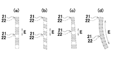
- FIG. 1 is a diagram for explaining the housing of the first embodiment of the present invention.
- FIG. 2 is a diagram showing a portion of the lattice structure of the housing of the second embodiment of the present invention, and is also a diagram showing a portion of the lattice structure of the housing of the third embodiment of the present invention.
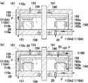
- 3(a) to 3(c) are cross-sectional views of a housing according to a fourth embodiment of the present invention.
- 4(a) is a perspective view of a portion of the housing of FIGS. 3(a) to 3(c)
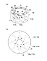
- FIG. 4(b) is a housing of FIGS. 3(a) to 3(c). 3(a) to 3(c) viewed in the vertical direction of the paper surface.
- FIG. 1 is a diagram for explaining the housing of the first embodiment of the present invention.
- FIG. 2 is a diagram showing a portion of the lattice structure of the housing of the second embodiment of the present invention, and is also a diagram showing a portion of
- FIG. 5(a) is a cross-sectional view of the housing of Modification 1 of the fourth embodiment
- FIG. 5(b) is a cross-sectional view of the housing of Modification 2 of the fourth embodiment
- FIG. 6(a) is a cross-sectional view of a housing according to Modification 3 of the fourth embodiment
- FIG. 6(b) is a cross-sectional view of a housing according to Modification 4 of the fourth embodiment
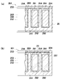
- FIG. 7(a) is a cross-sectional view of a housing according to a fifth embodiment of the present invention
- FIG. 7(b) is a cross-sectional view taken along line GG of FIG. 7(a)
- FIG. 7(c). is a cross-sectional view taken along line HH of FIG. 7(a).
- FIG. 8A is a cross-sectional view of the housing of Modification 1 of the fifth embodiment
- FIG. 8B is a cross-sectional view of the housing of Modification 2 of the fifth embodiment
- FIG. 9(a) is a cross-sectional view of the housing of the sixth embodiment of the present invention
- FIG. 9(b) is a perspective view of the housing of the sixth embodiment of the present invention
- FIG. 10(a) is a cross-sectional view of the housing of Modification 1 of the sixth embodiment
- FIG. 10(b) is a cross-sectional view of the housing of Modification 2 of the sixth embodiment.
- FIG. 1 shows three examples of housing 1, housings 1A, 1B and 1C.
- Enclosures 1A, 1B, 1C accommodate content 2 including heat source 3 .
- the housings 1A, 1B, 1C and the contents 2 are not limited to those shown in FIG.
- FIG. 1 shows a cross-section of housings 1A, 1B, 1C and contents 2.
- FIG. The housings 1A, 1B, 1C have a housing wall portion 5 that forms a housing space 4 that houses the content 2 including the heat source 3 .
- a housing wall portion 5 of the housing 1 ⁇ /b>A forms a refrigerant passage 10 through which a refrigerant flows between an outer surface 6 and an inner surface 7 of the housing wall portion 5 .
- the housing 1 ⁇ /b>A has a cooling structure in which heat generated by the heat source 3 is radiated to the outside through the coolant flowing through the coolant passage 10 .
- the refrigerant passage 10 is formed such that the maximum width W of the refrigerant passage 10 in a cross section across the refrigerant flow direction F is shorter than the length L of the refrigerant passage 10 in the refrigerant flow direction F.
- a lattice structure 20 is provided in the coolant passage 10 of the housing 1A.
- a cross section passing through the lattice structure 20 of the refrigerant passage 10 has a passage portion 10a provided with the lattice structure 20 and a passage portion 10b not provided with the lattice structure 20. As shown in FIG. That is, only part of the cross section of the coolant passage 10 is filled with the lattice structure portion 20 .
- the housings 1B and 1C have a cooling structure in which heat generated by the heat source 3 is radiated to the outside through the housing wall portion 5 .
- a lattice structure portion 20 is provided on the outer surface 6 of the housing wall portion 5 of the housing 1B.
- a lattice structure portion 20 is provided on the inner surface 7 of the housing wall portion 5 of the housing 1C.
- the housing 1 may have the coolant flow path 10 , and may have a lattice structure portion 20 provided in the coolant passage 10 and a lattice structure portion 20 provided on the outer surface 6 . Further, the housing 1 may have the coolant flow path 10 , and may have a lattice structure portion 20 provided in the coolant passage 10 and a lattice structure portion 20 provided on the inner surface 7 . Further, the housing 1 may have a lattice structure 20 provided on the outer surface 6 and a lattice structure 20 provided on the inner surface 7 . In this case, the housing 1 may or may not have the coolant passage 10 . Further, the housing 1 has a coolant passage 10, a lattice structure portion 20 provided in the coolant passage 10, a lattice structure portion 20 provided on the outer surface 6, and a lattice structure portion provided on the inner surface 7. 20.
- the lattice structure 20 includes a plurality of unit cells 21.
- a plurality of unit cells 21 included in the lattice structure 20 are formed in a plurality of cell spaces 22 of convex polyhedrons having the same number of vertices, the same number of faces, and the same number of sides.
- FIG. 1 shows four examples of unit cell 21, unit cells 21P, 21Q, 21R, and 21S. However, the configuration of the unit cell 21 is not limited to these.
- the cell spaces 22 are indicated by dashed lines.
- Each cell space 22 shares a face and a plurality of sides forming the face with an adjacent cell space 22 .
- a cell space 22 of the unit cells 21P, 21Q, 21R, and 21S is a regular hexahedron.
- the lattice structure 20 may include a plurality of unit cells 21 with differently shaped cell spaces 22 .
- the cell spaces 22 of the plurality of unit cells 21 included in the lattice structure 20 may all have the same shape.
- the internal space of each unit cell 21 is connected to the internal spaces of a plurality of unit cells 21 adjacent to this unit cell 21 so that the refrigerant can move.
- Each unit cell 21 has at least one of a bar-shaped portion that is not parallel to all sides of its own cell space 22 and a wall surface that is not parallel to all surfaces of its own cell space 22 .
- the unit cell 21P and the unit cell 21R are composed only of a plurality of bar-shaped portions that are not parallel to all sides of their own cell spaces 22.
- the unit cell 21Q is composed of a plurality of rod-shaped portions that are not parallel to all sides of its own cell space 22 and a plurality of rod-shaped portions that are parallel to the plurality of sides of its own cell space 22 .
- the unit cell 21S is composed only of walls having wall surfaces that are not parallel to all surfaces of its own cell space 22 .
- the lattice structure 20 includes at least one kind of unit cells 21 that are periodically repeated. The number of types of unit cells 21 that are periodically repeated may be one. A plurality of types of unit cells 21 may be periodically repeated.
- the plurality of types of unit cells 21 may be unit cells 21Q and unit cells 21R, for example.
- the plurality of types of unit cells 21 may differ only in the thickness of the rod-shaped portion or the thickness of the wall portion.
- Each of the lattice structures 20 has a plurality of unit cells 21 arranged in three directions: two directions intersecting each other and a direction intersecting a plane including these two directions.
- one of the three directions in the housing 1A is the coolant flow direction F, but the three directions may include the coolant flow direction F or may not include the coolant flow direction F. good.
- FIG. 1 shows two cross-sectional views of a portion of the housing wall portion 5 of the housing 1A where the refrigerant passage 10 is provided.
- One of the two cross-sectional views is a cross-section of the portion indicated by A in the drawing along the coolant flow direction F.
- the other of the two cross-sectional views is a cross-sectional view cut along the Da-Da line shown in the one cross-section.
- This cross-sectional view shows a cross section across the coolant flow direction F.
- the lattice structure portion 20 provided in the coolant passage 10 of the housing 1A is formed so as to be continuous with the housing wall portion 5 forming the coolant passage 10 .
- the lattice structure portion 20 provided in the coolant passage 10 of the housing 1A is configured so that the end of the lattice structure portion 20 in the direction intersecting the coolant flow direction F can flow in and out of the lattice structure portion 20. It is exposed.
- the plurality of unit cells 21 existing in one cross section of the refrigerant passage 10 of the housing 1A may all be the same type of unit cells 21 or may be a plurality of types of unit cells 21 . Also, the plurality of unit cells 21 existing in one cross section may or may not be connected to each other.
- the passage portion 10b of the refrigerant passage 10 where the lattice structure portion 20 is not provided has a plurality of unit cells 21 arranged in the first direction having the smallest inclination angle with respect to the refrigerant flow direction F among the three directions in which the unit cells 21 are arranged. , are arranged in a direction orthogonal to the first direction.
- the length of the passage portion 10b in the first direction is the length of the plurality of unit cells 21 .
- the first direction is the same direction as the coolant flow direction F (the inclination angle is 0°), but the first direction may be inclined with respect to the coolant flow direction F.
- the heat generated by the heat source 3 is transmitted to the refrigerant in the refrigerant passage 10 via the accommodation space 4 and the housing wall portion 5, and radiated to the outside by the refrigerant.
- at least part of the heat of the housing wall portion 5 is radiated to the refrigerant in the refrigerant passage 10 via the lattice structure portion 20 .
- FIG. 1 shows two cross-sectional views of a portion including part of the outer surface 6 of the housing wall portion 5 of the housing 1B.
- One of the two cross-sectional views is the cross-section of the portion indicated by B in the figure.
- the other of the two cross-sectional views is a cross-sectional view cut along the line Db-Db shown in the one cross-section.
- a lattice structure portion 20 provided on the outer surface 6 of the housing wall portion 5 of the housing 1B is formed so as to be continuous with the outer surface 6 .
- the lattice structure 20 provided on the outer surface 6 of the housing wall 5 of the housing 1B is perpendicular to the outer surface 6 of the housing wall 5 on which the lattice structure 20 is provided.
- the directional ends are exposed to allow fluid (eg, air) entry and exit.
- fluid eg, air
- the heat generated by the heat source 3 is transmitted to the housing wall portion 5 through the accommodation space 4 and radiated to the outside from the outer surface 6 of the housing wall portion 5.
- FIG. At this time, part of the heat of the housing wall portion 5 is radiated to the outside through the lattice structure portion 20, and the heat radiation to the outside from the outer surface 6 of the housing wall portion 5 is promoted.
- a lattice structure portion 20 provided on the inner surface 7 of the housing wall portion 5 of the housing 1C is formed so as to be continuous with the inner surface 7 .
- the lattice structure 20 provided on the inner surface 7 of the housing wall 5 of the housing 1B is perpendicular to the inner surface 7 of the housing wall 5 on which the lattice structure 20 is provided.
- the directional ends are exposed to allow fluid (eg, air) entry and exit.
- fluid eg, air
- the heat generated by the heat source 3 is transmitted to the housing wall portion 5 through the accommodation space 4 and radiated to the outside from the outer surface 6 of the housing wall portion 5.
- FIG. At this time, at least part of the heat in the accommodation space 4 is transferred to the lattice structure 20 and transferred from the lattice structure 20 to the housing wall 5 . This promotes heat transfer from the accommodation space 4 to the housing wall portion 5 .
- the first embodiment it is possible to improve the cooling performance of the housings 1A, 1B, and 1C while suppressing the enlargement of the housings 1A, 1B, and 1C, or to improve the cooling performance of the housings 1A, 1B, and 1C.
- the degree of freedom in designing the shapes of the housings 1A, 1B, and 1C can be improved while ensuring that.
- the length in the coolant flow direction F of the lattice structure 20 provided in the coolant passage 10 of the housing 1A may be longer than the length in the direction orthogonal to the coolant flow direction F.
- the coolant flows in the coolant flow direction F, the coolant is likely to flow in and out of the lattice structure 20 in a direction intersecting the coolant flow direction.
- a plurality of of unit cells 21 may be connected.
- the plurality of unit cells 21 are arranged such that the length L in the coolant flow direction F of the lattice structure 20 provided in the coolant passage 10 of the housing 1 is equal to or less than the maximum width of the coolant passage 10 in the cross section passing through the lattice structure 20. may be concatenated.
- the plurality of unit cells are arranged such that the length L in the coolant flow direction F of the lattice structure 20 provided in the coolant passage 10 of the housing 1 is longer than the circumferential length of the coolant passage 10 in the cross section passing through the lattice structure 20. 21 may be connected.
- the plurality of unit cells 21 are arranged such that the length L in the coolant flow direction F of the lattice structure 20 provided in the coolant passage 10 of the housing 1 is equal to or less than the circumferential length of the coolant passage 10 in the cross section passing through the lattice structure 20. may be connected.
- the lattice structure 20 provided in the coolant passage 10 of the housing 1 may include a plurality of unit cells 21 arranged in a line in the coolant flow direction F from one end to the other end of the lattice structure 20 .
- one of the three directions in which the unit cells 21 are arranged may be the same as the refrigerant flow direction F.
- Each unit cell 21 may have the same shape as any unit cell 21 of the lattice structure 20 .
- the lattice structure 20 may include unit cells 21 having a different shape from any unit cell 21 .
- FIGS. 2(a) to 2(d) A housing 1 according to a second embodiment and a third embodiment of the present invention will be described with reference to FIGS. 2(a) to 2(d).
- the second and third embodiments each have the configuration of the first embodiment.
- the third embodiment may have the configuration of the second embodiment.
- the cell spaces 22 are indicated by dashed lines. Illustration of the rod-shaped portion and/or the wall portion that constitute the unit cell 21 is omitted.
- FIGS. 2(a) to 2(d) show a plurality of unit cells 21 arranged in a line forming part of the lattice structure 20.
- the cell space 22 of the unit cell 21 shown in FIG. 2(a) may be a rectangular parallelepiped, or may be another convex polyhedron.
- the cell space 22 of the unit cell 21 shown in FIG. 2(b) has parallelogram faces.
- the cell space 22 of the unit cell 21 shown in FIG. 2B may be a parallelepiped or a convex polyhedron.
- the cell space 22 of the unit cell 21 shown in FIG. 2(c) has a trapezoidal surface.
- the cell space 22 of the unit cell 21 shown in FIG. 2(c) may be a truncated quadrangular pyramid or a convex polyhedron.
- FIGS. 2(a) to 2(d) has a non-rectangular square surface.
- cell spaces 22 of unit cells 21 of the same type are hatched.
- the direction in which the unit cells 21 are arranged as shown in FIGS. 2(a) to 2(d) is the E direction.
- a plurality of unit cells 21 shown in FIGS. 2(a) to 2(d) include at least one type of unit cells 21 periodically repeated in the E direction.
- the E direction coincides with the refrigerant flow direction F.
- the lattice structure portion 20 of the second embodiment includes at least one kind of unit cells 21 that are periodically repeated at least in the coolant flow direction F.
- FIG. 1 the lattice structure portion 20 of the second embodiment
- the E direction is a direction that intersects the coolant flow direction F.
- the lattice structure portion 20 of the third embodiment includes at least one kind of unit cells 21 that are periodically repeated in at least the direction intersecting the coolant flow direction F.
- the arrangement of the same type of unit cells 21 is not limited to the arrangement shown in FIGS. 2(a) to 2(d).
- the plurality of unit cells 21 shown in FIG. 2(a) may all be composed of the same type of unit cells 21 as shown in FIG. 2(d).
- a housing 101 according to a fourth embodiment of the present invention will be described with reference to FIGS. 3(a) to 3(c), 4(a), and 4(b).
- a housing 101 of the fourth embodiment has the configuration of the housing 1 of the first embodiment.
- the housing 101 of the fourth embodiment may have the configuration of the housing 1 of at least one of the second embodiment and the third embodiment.
- a housing 101 of the fourth embodiment accommodates a rotating electrical machine 190 .
- the rotating electric machine 190 may be a motor, a generator, or may have the functions of both a motor and a generator.
- the rotating electrical machine 190 may be an axial gap type rotating electrical machine 190 as shown in FIG.
- the rotary electric machine 190 may be an outer rotor type radial gap type rotary electric machine 190 as shown in c).
- the rotating electric machine 190 has a shaft 191 , a rotor 192 and a stator 193 .
- the shaft 191 is rotatably supported by the housing 101 via bearings.
- Rotor 192 is fixed to shaft 191 and rotates integrally with shaft 191 .
- the rotor 192 has magnets 192a.
- the stator 193 has a stator yoke 193a and a winding portion 193b. As shown in FIG.
- a rotor 192 and a stator 193 face each other in a direction parallel to the central axis of the shaft 191 .
- the rotor 192 is arranged radially inside the stator 193 .
- the magnets 192 a of the rotor 192 are arranged radially outward of the stator 193 .
- the housing 101 has a housing wall portion 105 that forms a housing space 104 that houses the rotating electric machine 190.
- the housing wall portion 105 has a substantially plate-shaped lower wall portion 151 , a cylindrical side wall portion 152 , and a substantially plate-shaped upper wall portion 153 .
- Side wall portion 152 connects upper wall portion 153 and lower wall portion 151 .
- the side wall portion 152 is formed integrally with the upper wall portion 153 .
- the side wall portion 152 may be integrally molded with the lower wall portion 151 .
- the lower wall portion 151 is located below the upper wall portion 153 in the vertical direction of the paper surface, it is not always located below the upper wall portion 153 when the housing 101 is used.
- the lower wall portion 151 may be positioned above the upper wall portion 153, and the lower wall portion 151 and the upper wall portion 153 may be horizontally aligned.
- Side wall portion 152 is positioned radially outward of rotating electric machine 190 .
- the stator 193 is fixed to the lower wall portion 151 and is in contact with the lower wall portion 151 or in contact with a member (not shown) that contacts the lower wall portion 151 .
- FIG. 3B the stator 193 is fixed to the side wall portion 152 and is in contact with the side wall portion 152 or in contact with a member (not shown) that contacts the side wall portion 152 .
- FIG. 3A the stator 193 is fixed to the lower wall portion 151 and is in contact with the lower wall portion 151 or in contact with a member (not shown) that contacts the lower wall portion 151 .
- the stator 193 is fixed to the side wall portion 152 and is in contact with the side wall portion 152 or in contact with a member (not shown) that
- the housing wall portion 105 has an inner cylindrical portion 154 connected to the lower wall portion 151 and positioned radially inside the stator 193 .
- the stator 193 is fixed to the inner tubular portion 154 and is in contact with the inner tubular portion 154 or in contact with a member (not shown) that contacts the inner tubular portion 154 .
- the housing wall portion 105 forms a plurality of refrigerant passages 110 .
- the refrigerant flowing through each refrigerant passage 110 may be gas (for example, air) or liquid.
- a fan (not shown) may be provided on the shaft 191 for sending the air outside the housing 101 to the inlet of the coolant passage 110 .
- the inlet and outlet of each coolant passage 110 are formed on the outer surface 106 of the housing wall portion 105 .
- a plurality of coolant passages 110 are formed at intervals in the circumferential direction around the central axis of shaft 191 .
- Each coolant passage 110 is formed in an upper wall portion 153 , a side wall portion 152 and a lower wall portion 151 .
- Each refrigerant passage 110 is composed of a refrigerant passage lower portion 110a, a refrigerant passage intermediate portion 110b, and a refrigerant passage upper portion 110c.
- the refrigerant passage lower portion 110 a is a portion of the refrigerant passage 110 formed in the lower wall portion 151 .
- the refrigerant passage intermediate portion 110 b is a portion of the refrigerant passage 110 formed in the side wall portion 152 .
- the coolant passage upper portion 110 c is a portion of the coolant passage 110 formed in the upper wall portion 153 .
- Each coolant passage 110 is provided with two lattice structure portions 20 .
- One of the two lattice structure portions 20 is provided on the lower wall portion 151 and the other lattice structure portion 20 is provided on the side wall portion 152 and the upper wall portion 153 .
- the two lattice structure portions 20 are provided throughout the coolant flow direction F of the coolant passage 110 .
- the two lattice structure portions 20 may be provided only in a portion of the coolant passage 110 in the coolant flow direction F.
- Each lattice structure 20 is integrally molded.
- the coolant passage 110 has a bent portion where the coolant flow direction F is bent, such as at a corner of the housing 101 .
- the coolant passage 110 has bent portions at both ends of the coolant passage lower portion 110a and both ends of the coolant passage upper portion 110c.
- 4A is a perspective view of the side wall portion 152.
- FIG. 4A the coolant flow direction F of the coolant passage intermediate portion 110b is spiral. That is, the coolant flow direction F of the coolant passage intermediate portion 110b is inclined in the circumferential direction with respect to the direction of the central axis of the shaft 191 .
- the cooling performance can be improved. Since the refrigerant passage intermediate portion 110 b is formed in a spiral shape on the cylindrical side wall portion 152 , the refrigerant flow direction F of the refrigerant passage intermediate portion 110 b gently curves along the side wall portion 152 .
- 4B is a view of the upper wall portion 153 viewed in the direction of the central axis of the shaft 191, and a view of the lower wall portion 151 viewed in the direction of the central axis of the shaft 191. FIG. As shown in FIG.
- the refrigerant passage upper portion 110c and the refrigerant passage lower portion 110a have curved portions in which the refrigerant flow direction F is substantially radial. Compared to the case where the refrigerant flow direction F of these portions is parallel to the radial direction or the straight line crossing the radial direction, the refrigerant passage upper portion 110c and the refrigerant passage lower portion 110a are longer in the refrigerant flow direction F. , can improve the cooling performance.
- the coolant passage lower portion 110a in FIG. 3A is a portion of the housing wall portion 105 in contact with the stator 193, a portion in contact with a member (not shown) in contact with the stator 193, or a minute gap. It is formed so as to pass through a position close to the part facing the stator 193 with an opening.
- the upper portion 110c of the coolant passage in FIG. 3B is a portion of the housing wall portion 105 in contact with the stator 193, a portion in contact with a member (not shown) in contact with the stator 193, or a minute gap. It is formed so as to pass through a position close to the part facing the stator 193 with an opening.
- the refrigerant passage lower portion 110a among the refrigerant passage lower portion 110a, the refrigerant passage intermediate portion 110b, and the refrigerant passage upper portion 110c is the portion where the stator 193 is in contact with the housing wall portion 105 or It is closest to the point where a member (not shown) that contacts the stator 193 is in contact. Therefore, the coolant flowing through the coolant passage 110 shown in FIGS. Since the lattice structure 20 is provided in the coolant passage 110 having high cooling performance in this manner, the cooling performance of the housing 101 can be further improved.
- the refrigerant passage lower portion 110a does not have to have a bent portion. That is, the refrigerant flow direction F of the entire refrigerant passage lower portion 110a may be the same as the refrigerant flow direction F of the refrigerant passage intermediate portion 110b.
- the coolant passage upper portion 110c may not have a bent portion. That is, the refrigerant flow direction F of the entire refrigerant passage upper portion 110c may be the same as the refrigerant flow direction F of the refrigerant passage intermediate portion 110b.
- the refrigerant flow direction F of the refrigerant passage intermediate portion 110b may be linear parallel to the direction of the center axis of the shaft 191 .
- the side wall portion 152 may have a square tubular shape. In this case, the coolant flow direction F of the coolant passage intermediate portion 110 b may be a straight line that is inclined with respect to the direction of the central axis of the shaft 191 .
- the housing 101 may have a plurality of types of refrigerant passages 110A, as shown in FIG. FIG. 5(a) shows an example in which the housing 101 of FIG. 3(a) is changed, but the housing 101 of FIGS. 3(b) and 3(c) may be changed.
- the housing 101 shown in FIG. 5A will be described below.
- a housing wall portion 105 of the housing 101 forms a plurality of first refrigerant passages 110A1 and a plurality of second refrigerant passages 110A2.
- the refrigerant passage 110A is a general term for the first refrigerant passage 110A1 and the second refrigerant passage 110A2.
- each coolant passage 110A is formed on the outer surface 106 of the housing wall portion 105 .
- the first refrigerant passage 110A1 differs from the refrigerant passage 110 of the fourth embodiment in the shape of the refrigerant passage lower portion 110a, and otherwise has the same configuration as the refrigerant passage 110 of the fourth embodiment.
- a refrigerant passage lower portion 110a of the refrigerant passage 110A1 is formed in a spiral shape that is continuous with a portion provided on the side wall portion 252 of the refrigerant passage 110A1.
- the second coolant passage 110A2 is formed only in the lower wall portion 151. As shown in FIG.
- the second refrigerant passage 110A2 has the same shape as most of the refrigerant passage lower portion 110a of the refrigerant passage 110 of the fourth embodiment, and differs from the refrigerant passage lower portion 110a in the shape near the outlet.
- the second refrigerant passage 110A2 is also curved in the vicinity of the outlet, similarly to the other portions.
- the first coolant passages 110A1 and the second coolant passages 110A2 are alternately arranged in the circumferential direction around the central axis of the shaft 191. As shown in FIG. Two lattice structure portions 20 are provided in each first coolant passage 110A1.
- One of the two lattice structure portions 20 is provided on the lower wall portion 151 and the other lattice structure portion 20 is provided on the side wall portion 152 and the upper wall portion 153 .
- the two lattice structure portions 20 are provided over the entire area of the first coolant passage 110A1 in the coolant flow direction F. As shown in FIG.
- the two lattice structure portions 20 may be provided only partially in the coolant flow direction F of the first coolant passage 110A1.
- Each lattice structure 20 is integrally molded.
- One lattice structure portion 20 is provided in each second coolant passage 110A2.
- the lattice structure portion 20 is provided over the entire area of the second refrigerant passage 110A2 in the refrigerant flow direction F. As shown in FIG.
- the lattice structure portion 20 may be provided only in a portion of the second coolant passage 110A2 in the coolant flow direction F.
- the lattice structure 20 is integrally molded.
- Modification 1 of the fourth embodiment has substantially the same locations where the refrigerant passages are formed as in the fourth embodiment, but the length of each refrigerant passage in the refrigerant flow direction F can be made shorter than in the fourth embodiment. , can improve the cooling performance. Since the lattice structure 20 is provided in the coolant passage 110A having high cooling performance in this manner, the cooling performance of the housing 101 can be further improved.
- the housing 101 may have an internal circulation refrigerant passage 110B for circulating the air in the housing space 104, as shown in FIG. 5B, for example.
- FIG. 5(b) shows an example in which the housing 101 of FIG. 3(a) is changed, but the housing 101 of FIGS. 3(b) and 3(c) may be changed.
- a fan (not shown) may be provided on shaft 191 or rotor 192 for sending air (refrigerant) in accommodation space 104 to internal circulation refrigerant passage 110B.
- the housing 101 shown in FIG. 5B will be described below.
- the housing wall portion 105 of the housing 101 has a plurality of internal circulation refrigerant passages 110B in addition to the plurality of first refrigerant passages 110A1 and the plurality of second refrigerant passages 110A2 of Modification 1 of the fourth embodiment.
- the internal circulation refrigerant passage 110B is included in the refrigerant passage of the present invention.
- the inlet and outlet of each internal circulation coolant passage 110B are formed on the inner surface 107 of the housing wall portion 105 .
- the plurality of internal circulation refrigerant passages 110B are formed at intervals in the circumferential direction around the central axis of the shaft 191 .
- Each internal circulation refrigerant passage 110B is formed in the upper wall portion 153 and the side wall portion 152 .
- the internal circulation refrigerant passages 110B and the first refrigerant passages 110A1 are alternately arranged in the circumferential direction around the central axis of the shaft 191. As shown in FIG.
- the portion formed in the side wall portion 252 of each internal circulation refrigerant passage 110B has a spiral shape similar to the portion formed in the side wall portion 252 of the first refrigerant passage 110A1.
- a portion formed in the upper wall portion 253 of each internal circulation refrigerant passage 110 ⁇ /b>B is curved in the same manner as the portion formed in the upper wall portion 253 of the refrigerant passage 110 .
- Each internal circulation refrigerant passage 110B has a connection portion between the curved portion and the portion including the inlet, a connection portion between the spiral portion and the portion including the outlet, and a connection portion between the spiral portion and the curved portion. is a bent portion.
- One lattice structure portion 20 is provided in each internal circulation refrigerant passage 110B.
- the lattice structure 20 is provided over the entire area in the refrigerant flow direction F of the internal circulation refrigerant passage 110B.
- the lattice structure portion 20 may be provided only in a portion of the internal circulation refrigerant passage 110B in the refrigerant flow direction F.
- the lattice structure 20 is integrally molded.
- the housing 101 of Modification 2 of the fourth embodiment has the internal circulation refrigerant passage 110B for circulating the air in the housing space 104, the cooling performance can be improved. Since the lattice structure 20 is provided in the internal circulation coolant passage 110B having high cooling performance in this way, the cooling performance of the housing 101 can be further improved.
- the refrigerant passage combined with the internal circulation refrigerant passage 110B is not limited to the first refrigerant passage 110A1 and the second refrigerant passage 110A2.
- the coolant passage 110 of the fourth embodiment may be provided instead of the first coolant passage 110A1.
- the refrigerant passage 110 of the fourth embodiment may be provided instead of the second refrigerant passage 110A2.
- the refrigerant passage 110 of the fourth embodiment may be provided instead of the first refrigerant passage 110A1 and the second refrigerant passage 110A2. Further, for example, at least one of the spiral portion and the curved portion of the internal circulation refrigerant passage 110B may be straight.
- FIG. 6(a) shows an example in which the housing 101 of FIG. 3(a) is changed, but the housing 101 of FIGS. 3(b) and 3(c) may be changed.
- the lattice structure 20 is provided only on a part of the outer surface 106 of the housing wall 105 even if it is provided on the entire outer surface 106 of the housing wall 105. good too. Since the lattice structure portion 20 is provided on the outer surface 106 of the housing wall portion 105, the cooling performance of the housing 101 can be improved.
- the housing 101 may have the refrigerant passage 110 as in the fourth embodiment. When housing 101 has coolant passage 110 , coolant passage 110 may or may not have lattice structure 20 .
- FIG. 6(b) shows an example in which the housing 101 of FIG. 3(a) is changed, but the housing 101 of FIGS. 3(b) and 3(c) may be changed.
- the lattice structure 20 is provided only on a part of the inner surface 107 of the housing wall 105 even if it is provided over the entire inner surface 107 of the housing wall 105. good too. Since the lattice structure portion 20 is provided on the inner surface 107 of the housing wall portion 105, the cooling performance of the housing 101 can be improved.
- the housing 101 may have the refrigerant passage 110 as in the fourth embodiment.
- coolant passage 110 may or may not have lattice structure 20 .
- the lattice structure portion 20 may be provided on the outer surface 106 of the housing wall portion 105 as in Modification 3 of the fourth embodiment.
- FIG. 7(b) is a cross-sectional view taken along line GG shown in FIG. 7(a).
- FIG. 7(c) is a cross-sectional view taken along line HH shown in FIG. 7(a).
- a housing 201 of the fifth embodiment has the configuration of the housing 1 of the first embodiment.
- the housing 201 of the fifth embodiment may have the structure of the housing 1 of at least one of the second embodiment and the third embodiment. As shown in FIGS.
- the housing 201 of the fifth embodiment accommodates a content 290 including a plurality of rechargeable power storage devices 291 .
- the power storage device 291 may be a cell or an assembled battery composed of a plurality of cells.
- the cells may be cylindrical, rectangular, or laminated. Heat is generated in the power storage device 291 when the power storage device 291 is discharged or charged.
- the power storage device 291 corresponds to the heat source of the present invention.
- the content 290 includes a heat dissipation member 292 with high thermal conductivity. Heat dissipation member 292 is arranged so as to be in contact with power storage device 291 .
- Contents 290 may include a battery management system (BMS: battery management system) that manages charging and discharging of power storage device 291 .
- BMS battery management system
- the housing 201 has a housing wall portion 205 that forms a housing space 204 that houses a content 290 including a plurality of power storage devices 291 .
- the housing 201 has a substantially rectangular parallelepiped shape.
- the housing wall portion 205 has a substantially plate-shaped lower wall portion 251 , a rectangular tubular side wall portion 252 , a substantially plate-shaped upper wall portion 253 , and a plurality of partition wall portions 254 .
- Side wall portion 252 connects upper wall portion 253 and lower wall portion 251 .
- the side wall portion 252 is formed integrally with the lower wall portion 251 .
- the side wall portion 252 may be integrally formed with the upper wall portion 253 .
- the lower wall portion 251 is located below the upper wall portion 253 in the vertical direction of the paper surface of FIG. 7A, it is not always located below the upper wall portion 253 when the housing 201 is used.
- the lower wall portion 251 may be positioned above the upper wall portion 253, and the lower wall portion 251 and the upper wall portion 253 may be horizontally aligned.
- a plurality of partition wall portions 254 are connected to the lower wall portion 251 .
- the plurality of partition wall portions 254 may be connected to the upper wall portion 253 without being connected to the lower wall portion 251 .
- a plurality of partition wall portions 254 may be connected to both the lower wall portion 251 and the upper wall portion 253 .
- Each partition wall portion 254 is arranged between a power storage device 291 and an adjacent power storage device 291 .
- a plurality of heat dissipation members 292 are in contact with the housing wall portion 205 .
- Each heat radiating member 292 contacts the lower wall portion 251 .
- each heat dissipation member 292 contacts at least one of the partition wall portion 254 and the side wall portion 252 .
- the portion of the heat radiating member 292 that contacts the housing wall portion 205 is not limited to this.
- the heat dissipation member 292 may function as a shock absorber.
- the housing wall portion 205 forms a plurality of refrigerant passages 210 .
- the refrigerant flowing through each refrigerant passage 210 may be gas (for example, air) or liquid.
- the inlet and outlet of each coolant passage 210 are formed in the outer surface 206 of the housing wall portion 205 .
- a plurality of coolant passages 210 are formed at intervals in the vertical direction of the paper surface of FIG. 7(a).
- the plurality of refrigerant passages 210 includes a plurality of first refrigerant passages 210A and second refrigerant passages 210B.
- Each first coolant passage 210 ⁇ /b>A is formed in a side wall portion 252 and a plurality of partition wall portions 254 .
- the second coolant passage 210B is formed in the lower wall portion 251 .
- Each coolant passage 210 is provided with one lattice structure 20 .
- the lattice structure portion 20 is provided over the entire area of the refrigerant passage 210 in the refrigerant flow direction F. As shown in FIG.
- the lattice structure portion 20 may be provided only in a portion of the coolant passage 210 in the coolant flow direction F.
- the lattice structure 20 is integrally molded.
- the first coolant passage 210A has a bent portion where the coolant flow direction F is bent at a corner portion of the housing 201 or the like.
- the first refrigerant passage 210A has a branch point where the refrigerant flow branches and a confluence point where the refrigerant flows join.
- the second coolant passage 210B has a bent portion at a corner of the housing 201 or the like, where the coolant flow direction F is bent.
- the second coolant passage 210B has a shape that can be drawn with a single stroke from the inlet to the outlet.
- a plurality of first coolant passages 210A are formed to surround a plurality of power storage devices 291 .
- the coolant flowing through the first coolant passage 210A easily receives the heat generated in the power storage device 291 .
- Most of the second refrigerant passage 210B is positioned directly below the power storage device 291 in the vertical direction of the paper surface of FIG. 7(a). Therefore, the coolant flowing through the second coolant passage 210 ⁇ /b>B easily receives the heat generated in the power storage device 291 . Since the lattice structure portion 20 is provided in the coolant passages 210A and 210B having high cooling performance in this manner, the cooling performance of the housing 201 can be further improved. Note that the housing wall portion 205 having the second refrigerant passage 210B may not have the plurality of first refrigerant passages 210A. The housing wall portion 205 having the plurality of first coolant passages 210A may not have the second coolant passages 210B.
- the lattice structure 20 may be provided on the entire outer surface 206 of the housing wall 205, or may be provided only on a part of the outer surface 206 of the housing wall 205. may be Since the lattice structure portion 20 is provided on the outer surface 206 of the housing wall portion 205, the cooling performance of the housing 101 can be improved. Further, in Modification 1 of the fifth embodiment, the housing 201 may have the refrigerant passage 210 as in the fifth embodiment. In this case, the refrigerant passage 210 may or may not be provided with the lattice structure portion 20 .
- Modification 2 of the fifth embodiment for example, as shown in FIG. may be provided.
- the lattice structure 20 may be provided on the entire inner surface 207 of the housing wall 205, or may be provided only on a part of the inner surface 207 of the housing wall 205. may have been Since the lattice structure portion 20 is provided on the inner surface 107 of the housing wall portion 205, the cooling performance of the housing 201 can be improved.
- the housing 201 may have the refrigerant passage 210 as in the fifth embodiment. In this case, the refrigerant passage 210 may or may not be provided with the lattice structure portion 20 .
- the lattice structure portion 20 may be provided on the outer surface 206 of the housing wall portion 205 in the same manner as in Modification 1 of the fifth embodiment.
- a housing 301 according to a sixth embodiment of the present invention will be described with reference to FIGS. 9(a) and 9(b).
- a housing 301 of the sixth embodiment has the configuration of the housing 1 of the first embodiment.
- the housing 301 of the sixth embodiment may have the configuration of the housing 1 of at least one of the second embodiment and the third embodiment.
- a housing 301 of the sixth embodiment accommodates an electronic device 390 .
- the electronic device 390 has a circuit board 391, electronic components 392 mounted on the surface of the circuit board 391, and a heat dissipation member 393 with high thermal conductivity.
- Circuit board 391 and electronic component 392 correspond to the heat source of the present invention.
- the heat dissipation member 393 is in contact with the back surface of the circuit board 391 .
- the housing 301 has a housing wall portion 305 that forms a housing space 304 that houses the electronic device 390 .
- the housing 301 has a substantially rectangular parallelepiped shape.
- the housing wall portion 305 has a substantially plate-shaped lower wall portion 351 , a rectangular tubular side wall portion 352 , and a substantially plate-shaped upper wall portion 353 .
- the side wall portion 352 connects the upper wall portion 353 and the lower wall portion 351 .
- the side wall portion 352 is formed integrally with the upper wall portion 353 .
- the side wall portion 352 may be integrally formed with the lower wall portion 351 .
- the lower wall portion 351 may be positioned above the upper wall portion 353, and the lower wall portion 351 and the upper wall portion 353 may be horizontally aligned.
- the circuit board 391 is fixed to the lower wall portion 351 .
- a heat dissipation member 393 is arranged between the circuit board 391 and the lower wall portion 351 . The heat dissipation member 393 is in contact with the lower wall portion 351 .
- housing wall portion 305 forms refrigerant passage 310 .
- the refrigerant flowing through the refrigerant passage 310 may be gas (for example, air) or liquid.
- the inlet and outlet of the coolant passage 310 are formed on the outer surface 306 of the housing wall portion 305 .
- the coolant passage 310 is formed in the lower wall portion 351 , the side wall portion 352 and the upper wall portion 353 .
- Two lattice structure portions 20 are provided in the coolant passage 310 .
- One of the two lattice structure portions 20 is provided on the lower wall portion 351 and the other lattice structure portion 20 is provided on the side wall portion 352 and the upper wall portion 353 .
- the two lattice structure portions 20 are provided over the entire area of the coolant passage 310 in the coolant flow direction F. As shown in FIG. The two lattice structure portions 20 may be provided only in a portion of the coolant passage 310 in the coolant flow direction F. Each lattice structure 20 is integrally molded.
- the coolant passage 310 has a bent portion where the coolant flow direction F is bent, such as at a corner of the housing 301 .
- the refrigerant passage 310 has a branch point where the flow of the refrigerant branches and a confluence point where the flow of the refrigerant joins.
- a portion of the coolant passage 310 is formed in the lower wall portion 351 of the housing wall portion 305 .
- part of the coolant passage 310 passes through a portion of the housing wall portion 305 that is most likely to receive heat from the electronic device 390 . Therefore, the coolant flowing through coolant passage 310 easily receives heat generated by circuit board 391 and electronic component 392 . Since the lattice structure 20 is provided in the coolant passage 310 having high cooling performance in this manner, the cooling performance of the housing 301 can be further improved. Note that the coolant passage 310 may be formed only in the lower wall portion 351 .
- Modification 1 of the sixth embodiment for example, as shown in FIG. may be provided.
- the lattice structure 20 may be provided over the entire outer surface 306 of the housing wall 305, or may be provided only on a part of the outer surface 306 of the housing wall 305. may be Since the lattice structure part 20 is provided on the outer surface 306 of the housing wall part 305, the cooling performance of the housing 301 can be improved.
- the housing 301 may have the refrigerant passage 310 as in the sixth embodiment. In this case, the refrigerant passage 310 may or may not be provided with the lattice structure portion 20 .
- the lattice structure 20 may be provided on the entire inner surface 307 of the housing wall 305, or may be provided only on a part of the inner surface 307 of the housing wall 305. may be Since the lattice structure portion 20 is provided on the inner surface 107 of the housing wall portion 205, the cooling performance of the housing 201 can be improved.
- the housing 301 may have the refrigerant passage 310 as in the sixth embodiment. In this case, the refrigerant passage 310 may or may not be provided with the lattice structure portion 20 .
- the lattice structure portion 20 may be provided on the outer surface 306 of the housing wall portion 305 as in Modification 1 of the sixth embodiment.
- the fourth embodiment and its modification examples 1 to 4 are merely examples in which the present invention is applied to a housing that accommodates a rotating electric machine.
- the configuration (including the shape of the coolant passage) of the housing that accommodates the rotating electric machine to which the present invention is applied is not limited to the configuration of the fourth embodiment and its first and second modifications.
- the coolant passage may be formed along the circumferential direction around the central axis of the shaft.
- the fifth embodiment and its modified examples 1 and 2 are merely examples in which the present invention is applied to a housing that accommodates a power storage device.
- the configuration of the housing (including the shape of the refrigerant passage) that accommodates the power storage device to which the present invention is applied is not limited to the configuration of the fifth embodiment and its first and second modifications.
- the sixth embodiment and its modified examples 1 and 2 are merely examples in which the present invention is applied to a housing that accommodates an electronic device.
- the configuration of the housing (including the shape of the coolant passage) that accommodates the electronic device to which the present invention is applied is not limited to the configuration of the sixth embodiment and its modification examples 1 and 2.
- Coolant passage 20 Lattice structure 21, 21P, 21Q, 21R, 21S: Unit cell 22: Cell space 191: Rotating electric machine (contents) 192: Rotor (heat source) 193: Stator (heat source) 291: Power storage device (heat source) 390: Electronic equipment (contents) 391: Circuit board (heat source) 392: Electronic components (heat sources) F: Refrigerant flow direction
Landscapes
- Engineering & Computer Science (AREA)
- Physics & Mathematics (AREA)
- Thermal Sciences (AREA)
- Microelectronics & Electronic Packaging (AREA)
- Power Engineering (AREA)
- Cooling Or The Like Of Semiconductors Or Solid State Devices (AREA)
- Cooling Or The Like Of Electrical Apparatus (AREA)
- Panels For Use In Building Construction (AREA)
- Road Paving Structures (AREA)
- Superstructure Of Vehicle (AREA)
Abstract
筐体(1)は、3方向にそれぞれユニットセル(21)が複数並ぶラティス構造部(20)を含み、下記構成1および下記構成2の少なくとも一方を備えている。 構成1:筐体壁部(5)が冷媒通路(10)を形成する。冷媒通路を形成する筐体壁部とラティス構造部とが連続する。冷媒通路は、ラティス構造部を通る横断面に、ラティス構造部が設けられた通路部分(10a)と、ラティス構造部が設けられていない通路部分(10b)とを有する。ラティス構造部に冷媒流れ方向と交差する方向の端から冷媒の出入りが可能となるように、ラティス構造部の当該端がむき出しになっている。 構成2:筐体壁部の外表面または内表面とラティス構造部とが連続する。ラティス構造部に、筐体壁部のラティス構造部が設けられる外表面または内表面と直交する方向の端から、流体の出入りが可能となるように、ラティス構造部の当該端がむき出しになっている。
Description
この発明は、筐体、特に、熱源を含む内容物を収容する筐体に関する。
熱源を含む内容物を収容する筐体は、熱源を含む内容物を収容する収容空間を形成する筐体壁部を有する。従来、熱源を含む内容物を収容する筐体として、熱源で発生した熱を外部に放熱するための冷却構造を有するものがある。
筐体の冷却構造として、筐体壁部の外表面と内表面との間に細長い冷媒通路が形成される場合がある。熱源で発生した熱は、冷媒通路内を流れる冷媒を介して外部に放熱される。細長い冷媒通路とは、冷媒流れ方向を横断する横断面における冷媒通路の最大幅が冷媒通路の冷媒流れ方向の長さよりも短くなるように形成された冷媒通路である。例えば、特許文献1および特許文献2において、モータ(熱源)を収容する筐体は、細長い冷媒通路が形成された筐体壁部を有する。特許文献1および特許文献2の筐体壁部は、モータのステータを保持する内筒と外筒を含む。冷媒通路は、内筒と外筒との間に形成される。特許文献1および特許文献2では、冷却効率を高くするための工夫が冷媒通路に施されている。具体的には、特許文献1および特許文献2では、冷媒通路の横断面積が部分的に小さくなるように複数の絞り部(凹部)が設けられている。また、特許文献1の冷媒通路の内部には、少なくとも内筒に連結された複数のフィンが設けられている。特許文献2の冷媒通路には、内筒と外筒を連結する複数の円柱が設けられている。特許文献1では、絞り部によって冷媒流に乱流を発生させ、絞り部の下流に設けたフィンに乱流化した冷媒流を接触させることで熱交換の効率の向上を図っている。特許文献2では、絞り部と円柱によって冷媒流に乱流を発生させ、冷媒の淀みをなくすことで熱交換の効率の向上を図っている。
また、筐体の冷却構造として、例えば特許文献3のように、筐体壁部の表面に複数の放熱フィンを有する場合がある。熱源で発生した熱は、放熱フィンから筐体の外部に放熱される。
熱源を含む内容物を収容する筐体は、大型化を抑制しつつ冷却性能を向上させることが求められる。また、熱源を含む内容物を収容する筐体は、筐体の冷却性能を確保しつつ、筐体の形状の設計自由度を高めることが求められる。
本発明は、筐体の大型化を抑制しつつ筐体の冷却性能を向上することができる、または、筐体の冷却性能を確保しつつ筐体の形状の設計自由度を向上させることができる、筐体を提供することを目的とする。
熱源を含む内容物を収容する筐体は、以下の2つの理由により筐体の外面および内面の形状が制約を受けるという課題を有する。第1の理由は、内容物の形状および筐体を搭載する際の周囲の部品との干渉を考慮する必要があるためである。第2の理由は、内容物の支持および筐体自身の支持に必要な剛性および強度を確保する必要があるためである。
また、筐体が冷却構造を有する場合、さらに以下の課題が存在する。筐体の外面および内面の形状の制約を受ける筐体は、筐体の大型化を抑制しつつ冷却性能を向上させる、または、冷却性能を確保しつつ筐体形状の設計自由度を向上させることが求められる。
冷却構造として筐体壁部の外表面と内表面との間に細長い冷媒通路が形成される場合には、さらに以下の課題が存在する。筐体の外面および内面の形状が制約を受けることにより、筐体壁部の内部に形成される冷媒通路の形状が制約を受ける。
発明者らは、筐体の大型化を抑制しつつ筐体の冷却性能を向上させる、または、筐体の冷却性能を確保しつつ筐体の形状の設計自由度を向上させるために、特許文献1および特許文献2の筐体および筐体壁部についてより詳細に研究した。特許文献1および特許文献2では、細長い冷媒通路の横断面積を絞り部によって部分的に変更することで、乱流を発生させて冷却性能の向上を図っている。しかし、冷媒は横断面積が小さくなった箇所を通過した後に流速が低下するため、絞り部による乱流の発生範囲は限定的である。しかも、特許文献1および特許文献2の絞り部は、単純な絞り形状であるため乱流を構成する渦が大きくなりやすい。また、特許文献2では、冷媒通路の内部に形成した複数の円柱が、円柱の周囲に冷媒の乱流を発生させる。この乱流による攪拌作用が冷媒の淀みを低減し、それにより熱交換の効率を高めて冷却性能を高めている。しかし、円柱によって生じる乱流の発生範囲は限定的である。しかも、円柱によって生じる乱流を構成する渦は大きくなりやすい。また、円柱によって乱流を生じさせるには高い流速が必要である。流速が低い場合、カルマン渦列しか生じないので、攪拌作用が小さい。また、筐体の外面および内面の形状が制約を受けるため、冷媒通路の形状、絞り部の位置、ならびに、円柱の向きおよび位置は制約を受ける。そのため、より詳細に観察すると、特許文献1および特許文献2では、冷媒通路の横断面における冷媒の流れる位置および/または冷媒の流速に関して偏りが発生しており、冷却効率を向上できる余地が存在する。
また、冷却構造として、筐体壁部の表面にフィンを設ける場合、以下の課題が存在する。筐体はフィンを設けた分だけ大型化する。また、筐体壁部にフィンを設けるための大きな領域を確保する必要があるため、筐体の形状の制約が高くなる。
発明者らは、筐体の大型化を抑制しつつ冷却性能を向上させるか、もしくは、冷却性能を確保しつつ筐体の形状の設計自由度を向上させるために、特許文献3の筐体壁部の表面に複数のフィンが設けられた筐体についてより詳細に研究した。特許文献3では、フィンの周囲の空気は、フィンの表面に沿って流れることしかできず、流れ方向に制約を受ける。そのため、冷却性能を向上させる余地が存在する。筐体壁部の表面に設ける冷却構造の冷却性能を高めることで、冷却構造を小型化でき、筐体壁部の表面にフィンを設ける場合より筐体を小型化できる余地がある。また、フィンは薄板状のものであるので、筐体壁部の表面に複数のフィンを設けても筐体自体の剛性および強度の向上にあまり寄与しない。そのため、筐体壁部の表面に設ける冷却構造の剛性および強度を高めることで、筐体を小型化できる余地が存在する。
このように、筐体の外面および内面の形状の制約を受けても、筐体の大型化を抑制しつつ冷却性能を向上させる、または、冷却性能を確保しつつ筐体形状の設計の自由度を向上させることができる冷却構造が求められる。
また、筐体が冷却構造を有する場合、さらに以下の課題が存在する。筐体の外面および内面の形状の制約を受ける筐体は、筐体の大型化を抑制しつつ冷却性能を向上させる、または、冷却性能を確保しつつ筐体形状の設計自由度を向上させることが求められる。
冷却構造として筐体壁部の外表面と内表面との間に細長い冷媒通路が形成される場合には、さらに以下の課題が存在する。筐体の外面および内面の形状が制約を受けることにより、筐体壁部の内部に形成される冷媒通路の形状が制約を受ける。
発明者らは、筐体の大型化を抑制しつつ筐体の冷却性能を向上させる、または、筐体の冷却性能を確保しつつ筐体の形状の設計自由度を向上させるために、特許文献1および特許文献2の筐体および筐体壁部についてより詳細に研究した。特許文献1および特許文献2では、細長い冷媒通路の横断面積を絞り部によって部分的に変更することで、乱流を発生させて冷却性能の向上を図っている。しかし、冷媒は横断面積が小さくなった箇所を通過した後に流速が低下するため、絞り部による乱流の発生範囲は限定的である。しかも、特許文献1および特許文献2の絞り部は、単純な絞り形状であるため乱流を構成する渦が大きくなりやすい。また、特許文献2では、冷媒通路の内部に形成した複数の円柱が、円柱の周囲に冷媒の乱流を発生させる。この乱流による攪拌作用が冷媒の淀みを低減し、それにより熱交換の効率を高めて冷却性能を高めている。しかし、円柱によって生じる乱流の発生範囲は限定的である。しかも、円柱によって生じる乱流を構成する渦は大きくなりやすい。また、円柱によって乱流を生じさせるには高い流速が必要である。流速が低い場合、カルマン渦列しか生じないので、攪拌作用が小さい。また、筐体の外面および内面の形状が制約を受けるため、冷媒通路の形状、絞り部の位置、ならびに、円柱の向きおよび位置は制約を受ける。そのため、より詳細に観察すると、特許文献1および特許文献2では、冷媒通路の横断面における冷媒の流れる位置および/または冷媒の流速に関して偏りが発生しており、冷却効率を向上できる余地が存在する。
また、冷却構造として、筐体壁部の表面にフィンを設ける場合、以下の課題が存在する。筐体はフィンを設けた分だけ大型化する。また、筐体壁部にフィンを設けるための大きな領域を確保する必要があるため、筐体の形状の制約が高くなる。
発明者らは、筐体の大型化を抑制しつつ冷却性能を向上させるか、もしくは、冷却性能を確保しつつ筐体の形状の設計自由度を向上させるために、特許文献3の筐体壁部の表面に複数のフィンが設けられた筐体についてより詳細に研究した。特許文献3では、フィンの周囲の空気は、フィンの表面に沿って流れることしかできず、流れ方向に制約を受ける。そのため、冷却性能を向上させる余地が存在する。筐体壁部の表面に設ける冷却構造の冷却性能を高めることで、冷却構造を小型化でき、筐体壁部の表面にフィンを設ける場合より筐体を小型化できる余地がある。また、フィンは薄板状のものであるので、筐体壁部の表面に複数のフィンを設けても筐体自体の剛性および強度の向上にあまり寄与しない。そのため、筐体壁部の表面に設ける冷却構造の剛性および強度を高めることで、筐体を小型化できる余地が存在する。
このように、筐体の外面および内面の形状の制約を受けても、筐体の大型化を抑制しつつ冷却性能を向上させる、または、冷却性能を確保しつつ筐体形状の設計の自由度を向上させることができる冷却構造が求められる。
本発明の一実施形態の筐体は、以下の構成を有する。
熱源を含む内容物を収容する収容空間を形成する筐体壁部を有する筐体であって、
互いに交差する2方向とこれら2方向を含む平面と交差する方向との3方向にそれぞれユニットセルが複数並ぶラティス構造部を含み、熱源で発生した熱が外部に放熱される冷却構造を有し、
前記ラティス構造部を構成する複数のユニットセルは、同数の頂点、同数の面、および同数の辺を有する凸多面体の複数のセル空間に形成され、
各セル空間は、隣接する前記セル空間と1つの面とその面を形成する複数の辺を共有し、
前記ラティス構造部を構成する前記複数のユニットセルは、周期的に繰り返される少なくとも1種類の前記ユニットセルを含み、
前記ラティス構造部を構成する前記複数のユニットセルの各々は、自身の前記セル空間の全ての辺と平行でない棒状部および自身の前記セル空間の全ての面と平行でない壁面の少なくとも一方を有し、
各ユニットセルの内部空間は、このユニットセルに隣接する複数の前記ユニットセルの内部空間と、流体又は冷媒が移動できるようにつながっており、
下記構成1および下記構成2の少なくとも一方を備えている。
構成1:前記筐体壁部は、前記筐体壁部の外表面と内表面との間に、前記冷媒が流れる冷媒通路を形成し、
前記冷媒通路は、冷媒流れ方向を横断する横断面における前記冷媒通路の最大幅が前記冷媒通路の前記冷媒流れ方向の長さよりも短くなるように形成され、
前記筐体は、前記熱源で発生した熱が前記冷媒通路内を流れる前記冷媒を介して外部に放熱される前記冷却構造を有し、
前記冷媒通路を形成する前記筐体壁部と前記ラティス構造部とが連続するように形成され、
前記冷媒通路は、前記ラティス構造部を通る前記横断面に、前記ラティス構造部が設けられた通路部分と、前記ラティス構造部が設けられていない通路部分とを有し、
前記冷媒通路の前記ラティス構造部が設けられていない通路部分は、前記3方向のうち前記冷媒流れ方向に対する傾斜角度が最も小さい第1方向に並ぶ複数の前記ユニットセルと、前記第1方向と直交する第2方向に並び、
前記ラティス構造部に前記冷媒流れ方向と交差する方向の端から前記冷媒の出入りが可能となるように、前記ラティス構造部の当該端がむき出しになっている。
構成2:前記筐体壁部の外表面または内表面と前記ラティス構造部とが連続するように形成され、且つ、前記ラティス構造部に、前記筐体壁部の前記ラティス構造部が設けられる前記外表面または前記内表面と直交する方向の端から、前記流体の出入りが可能となるように、前記ラティス構造部の当該端がむき出しになっている。
熱源を含む内容物を収容する収容空間を形成する筐体壁部を有する筐体であって、
互いに交差する2方向とこれら2方向を含む平面と交差する方向との3方向にそれぞれユニットセルが複数並ぶラティス構造部を含み、熱源で発生した熱が外部に放熱される冷却構造を有し、
前記ラティス構造部を構成する複数のユニットセルは、同数の頂点、同数の面、および同数の辺を有する凸多面体の複数のセル空間に形成され、
各セル空間は、隣接する前記セル空間と1つの面とその面を形成する複数の辺を共有し、
前記ラティス構造部を構成する前記複数のユニットセルは、周期的に繰り返される少なくとも1種類の前記ユニットセルを含み、
前記ラティス構造部を構成する前記複数のユニットセルの各々は、自身の前記セル空間の全ての辺と平行でない棒状部および自身の前記セル空間の全ての面と平行でない壁面の少なくとも一方を有し、
各ユニットセルの内部空間は、このユニットセルに隣接する複数の前記ユニットセルの内部空間と、流体又は冷媒が移動できるようにつながっており、
下記構成1および下記構成2の少なくとも一方を備えている。
構成1:前記筐体壁部は、前記筐体壁部の外表面と内表面との間に、前記冷媒が流れる冷媒通路を形成し、
前記冷媒通路は、冷媒流れ方向を横断する横断面における前記冷媒通路の最大幅が前記冷媒通路の前記冷媒流れ方向の長さよりも短くなるように形成され、
前記筐体は、前記熱源で発生した熱が前記冷媒通路内を流れる前記冷媒を介して外部に放熱される前記冷却構造を有し、
前記冷媒通路を形成する前記筐体壁部と前記ラティス構造部とが連続するように形成され、
前記冷媒通路は、前記ラティス構造部を通る前記横断面に、前記ラティス構造部が設けられた通路部分と、前記ラティス構造部が設けられていない通路部分とを有し、
前記冷媒通路の前記ラティス構造部が設けられていない通路部分は、前記3方向のうち前記冷媒流れ方向に対する傾斜角度が最も小さい第1方向に並ぶ複数の前記ユニットセルと、前記第1方向と直交する第2方向に並び、
前記ラティス構造部に前記冷媒流れ方向と交差する方向の端から前記冷媒の出入りが可能となるように、前記ラティス構造部の当該端がむき出しになっている。
構成2:前記筐体壁部の外表面または内表面と前記ラティス構造部とが連続するように形成され、且つ、前記ラティス構造部に、前記筐体壁部の前記ラティス構造部が設けられる前記外表面または前記内表面と直交する方向の端から、前記流体の出入りが可能となるように、前記ラティス構造部の当該端がむき出しになっている。
構成1によると、冷媒通路に、互いに交差する2方向とこれら2方向を含む平面と交差する方向との3方向にそれぞれユニットセルが複数並ぶラティス構造部が設けられている。また、冷媒通路は、ラティス構造部を通る横断面に、ラティス構造部が設けられた通路部分とラティス構造部が設けられていない通路部分とを有する。すなわち、冷媒通路のラティス構造部を通る横断面の一部分のみがラティス構造部で埋まっている。また、ラティス構造部に冷媒流れ方向と交差する方向の端から冷媒の出入りが可能となるように、ラティス構造部の当該端がむき出しになっている。したがって、冷媒通路では、ラティス構造部に冷媒流れ方向と交差する方向の端から内部に冷媒が出入りしつつ、ラティス構造部内を冷媒が流れる。ラティス構造部は、周期的に繰り返される少なくとも1種類のユニットセルを含む。複数のユニットセルは、同数の頂点、同数の面、および同数の辺を有する凸多面体の複数のセル空間にそれぞれ形成される。セル空間は、隣接するセル空間と1つの面およびその面を形成する複数の辺を共有する。各ユニットセルは、自身のセル空間の全ての辺と平行でない棒状部および自身のセル空間の全ての面と平行でない壁面の少なくとも一方を有する。各ユニットセルの内部空間は隣接する複数のユニットセルの内部空間と冷媒が移動できるようにつながっている。冷媒がこのような構成のラティス構造部の内部を流れることにより、乱流場に大きな渦が生じることを抑えられつつ、冷媒通路を流れる冷媒を分流させるとともに冷媒流に小さな渦を加えることができる。しかも、冷媒通路の内部に円柱を設ける場合と冷媒の流速が同じ場合、より攪拌作用の高い乱流を発生させることができる。そのため、筐体の外面および内面の形状の制約、ならびに、これによる冷媒通路の位置等の制約があっても、これらの制約の影響を受けずに、冷媒通路のラティス構造部を通る横断面における冷媒の流れる位置および/または冷媒の流速に関する偏りおよび/または流速をラティス構造部によってより調整しやすい。各ユニットセルの形状、ユニットセルの並べ方、ならびに、ユニットセル内の棒状部および壁面の向きおよび位置によって、冷媒通路における流体の流れ(熱の流れ)および/または流体の流速をコントロールすることができる。したがって、筐体の大型化を抑制しつつ筐体の冷却性能を向上させることができる、または、筐体の冷却性能を確保しつつ筐体の形状の設計自由度をより向上できる。
また、上記の通り、各ユニットセルの形状、ユニットセルの並べ方、ユニットセル内の棒状部および壁面の向きおよび位置によって、筐体の形状の制約を受けずに、冷媒通路における流体の流れ(熱の流れ)および/または流体の流速をコントロールすることができる。したがって、筐体の形状の制約を受けずに冷却性能を向上できる。冷却性能が向上されたことで、冷媒通路を小さくすることができる。
さらに、ラティス構造部が棒状部または壁面を有する複数のユニットセルを含むものであるため、各棒状部および/または壁面を、上述した特許文献1および特許文献2の円柱、またはフィンと比べて小さくすることができる。したがって、円柱、またはフィンを設ける場合よりも抵抗を小さくできる。これにより、冷媒通路を小さくできる。
さらに、冷媒通路では、ラティス構造部が設けられている通路部分においてラティス構造部が設けられていない通路部分よりも抵抗が大きい。したがって、ラティス構造部を通る横断面の面積が同じであれば、冷媒通路のラティス構造部を通る横断面の一部分のみがラティス構造部で埋まっている方が、冷媒通路のラティス構造部を通る横断面全体がラティス構造で埋まっている場合よりも抵抗が小さい。本発明では、冷媒通路が、ラティス構造部を通る横断面にラティス構造が設けられた通路部分とラティス構造部が設けられていない通路部分とを有するので、冷媒通路の抵抗という観点において、冷媒通路のラティス構造部を通る横断面全体がラティス構造部で埋まっている場合に比べて、冷媒通路の横断面の面積をより小さくできる。
そして、本発明では、冷媒通路を小さくできるので、筐体の大型化を抑制しつつ冷却性能を向上させる、もしくは、冷却性能を確保しつつ筐体形状の設計の自由度を向上させることができる。
さらに、本発明では、冷媒通路にラティス構造部が設けられる。したがって、ラティス構造部により筐体の剛性および強度を高くすることができる。そして、剛性および強度が高いことで筐体形状の設計の自由度を向上できる、もしくは、ラティス構造部によって剛性および強度を確保できる分、冷却性能をより向上させても筐体の大型化を抑制できる。
筐体壁部に複数のフィンを設ける場合には、流体はフィンの表面に沿った方向にしか流れないので、流体が筐体壁部の表面に沿った方向に流れるとしてもフィンの長手方向に沿った方向にしか流れない。これに対して、本発明の構成2によると、筐体壁部の外表面または内表面と、互いに交差する2方向とこれら2方向を含む平面と交差する方向との3方向にそれぞれユニットセルが複数並ぶラティス構造部とが連続するように形成されている。また、ラティス構造部に、筐体壁部のラティス構造部が設けられる外表面または内表面と直交する方向の端から流体の出入りが可能となるように、ラティス構造部の当該端がむき出しになっている。ラティス構造部は、周期的に繰り返される少なくとも1種類のユニットセルを含む。複数のユニットセルは、同数の頂点、同数の面、および同数の辺を有する凸多面体の複数のセル空間にそれぞれ形成される。セル空間は、隣接するセル空間と1つの面およびその面を形成する複数の辺を共有する。各ユニットセルは、自身のセル空間の全ての辺と平行でない棒状部および自身のセル空間の全ての面と平行でない壁面の少なくとも一方を有する。各ユニットセルの内部空間は隣接する複数のユニットセルの内部空間と冷媒が移動できるようにつながっている。このような構成のラティス構造部内を流体が流れるため、例えば筐体壁部の表面に沿った複数の方向に流体が流れることもできる。したがって、ラティス構造部を設ける構成では、複数のフィンを設ける構成よりも冷却性能を高くすることができる。また、各ユニットセルの形状、ユニットセルの並べ方、ならびに、ユニットセル内の棒状部および壁面の向きおよび位置によって、流体の流れ(熱の流れ)をコントロールすることができる。それにより、冷却性能をより向上させることができる。その結果、複数のフィンを設ける場合のフィンの大きさよりも、ラティス構造部を小さくすることができる。すなわち、筐体壁部の厚み方向(外表面と内表面とが並ぶ方向)においてラティス構造部を小さくする、および/または、筐体壁部の外表面または内表面において、ラティス構造部を設ける領域を小さくすることができる。これらのことから、筐体の大型化を抑制しつつ冷却性能を向上できる。また、筐体壁部の表面においてラティス構造部が設けられる領域を複数のフィンが設けられる領域よりも小さくした場合、冷却性能を確保しつつ筐体形状の設計自由度を向上できる。
また、筐体壁部の表面に複数のフィンを設ける構成とした場合、各フィンは冷却性能を得るために薄板状に構成され、フィン同士は間隔をあけて配置され、片持ち支持された部分以外の部分では互いに連結されていない。そのため、フィンは、剛性および強度がそれほど高くない。これに対して、ラティス構造部は、互いに直交する3方向にそれぞれ複数のユニットセルが並ぶことによって構成されており、各ユニットセルが、セル空間を構成する全ての辺と平行でない棒状部またはセル空間の全ての面と平行でない壁面を有する。これにより、ラティス構造部では、上記3方向において、複数の棒状部または複数の壁面が連結される。これにより、ラティス構造部は、複数のフィンの集合に比べて、冷却性能を向上させつつも、剛性および強度を高くできる。ラティス構造部の剛性および強度が高いことで、筐体の剛性および強度を高める、または、筐体の剛性および強度を維持しつつ筐体壁部のラティス構造部と連続する部分の厚みを薄くできる。そして、筐体の剛性および強度を高めた場合、筐体形状の設計の自由度を向上できる。また、筐体の剛性および強度を確保しつつ筐体壁部の厚みを薄くした場合、冷却性能をより向上させても筐体の大型化を抑制できる。さらに、筐体壁部の厚みを薄くすることで筐体形状の設計の自由度を向上できる。
以上により、本発明の筐体は、筐体の大型化を抑制しつつ筐体の冷却性能を向上させることができる、または、筐体の冷却性能を確保しつつ筐体の形状の設計自由度を向上させることができる。
また、上記の通り、各ユニットセルの形状、ユニットセルの並べ方、ユニットセル内の棒状部および壁面の向きおよび位置によって、筐体の形状の制約を受けずに、冷媒通路における流体の流れ(熱の流れ)および/または流体の流速をコントロールすることができる。したがって、筐体の形状の制約を受けずに冷却性能を向上できる。冷却性能が向上されたことで、冷媒通路を小さくすることができる。
さらに、ラティス構造部が棒状部または壁面を有する複数のユニットセルを含むものであるため、各棒状部および/または壁面を、上述した特許文献1および特許文献2の円柱、またはフィンと比べて小さくすることができる。したがって、円柱、またはフィンを設ける場合よりも抵抗を小さくできる。これにより、冷媒通路を小さくできる。
さらに、冷媒通路では、ラティス構造部が設けられている通路部分においてラティス構造部が設けられていない通路部分よりも抵抗が大きい。したがって、ラティス構造部を通る横断面の面積が同じであれば、冷媒通路のラティス構造部を通る横断面の一部分のみがラティス構造部で埋まっている方が、冷媒通路のラティス構造部を通る横断面全体がラティス構造で埋まっている場合よりも抵抗が小さい。本発明では、冷媒通路が、ラティス構造部を通る横断面にラティス構造が設けられた通路部分とラティス構造部が設けられていない通路部分とを有するので、冷媒通路の抵抗という観点において、冷媒通路のラティス構造部を通る横断面全体がラティス構造部で埋まっている場合に比べて、冷媒通路の横断面の面積をより小さくできる。
そして、本発明では、冷媒通路を小さくできるので、筐体の大型化を抑制しつつ冷却性能を向上させる、もしくは、冷却性能を確保しつつ筐体形状の設計の自由度を向上させることができる。
さらに、本発明では、冷媒通路にラティス構造部が設けられる。したがって、ラティス構造部により筐体の剛性および強度を高くすることができる。そして、剛性および強度が高いことで筐体形状の設計の自由度を向上できる、もしくは、ラティス構造部によって剛性および強度を確保できる分、冷却性能をより向上させても筐体の大型化を抑制できる。
筐体壁部に複数のフィンを設ける場合には、流体はフィンの表面に沿った方向にしか流れないので、流体が筐体壁部の表面に沿った方向に流れるとしてもフィンの長手方向に沿った方向にしか流れない。これに対して、本発明の構成2によると、筐体壁部の外表面または内表面と、互いに交差する2方向とこれら2方向を含む平面と交差する方向との3方向にそれぞれユニットセルが複数並ぶラティス構造部とが連続するように形成されている。また、ラティス構造部に、筐体壁部のラティス構造部が設けられる外表面または内表面と直交する方向の端から流体の出入りが可能となるように、ラティス構造部の当該端がむき出しになっている。ラティス構造部は、周期的に繰り返される少なくとも1種類のユニットセルを含む。複数のユニットセルは、同数の頂点、同数の面、および同数の辺を有する凸多面体の複数のセル空間にそれぞれ形成される。セル空間は、隣接するセル空間と1つの面およびその面を形成する複数の辺を共有する。各ユニットセルは、自身のセル空間の全ての辺と平行でない棒状部および自身のセル空間の全ての面と平行でない壁面の少なくとも一方を有する。各ユニットセルの内部空間は隣接する複数のユニットセルの内部空間と冷媒が移動できるようにつながっている。このような構成のラティス構造部内を流体が流れるため、例えば筐体壁部の表面に沿った複数の方向に流体が流れることもできる。したがって、ラティス構造部を設ける構成では、複数のフィンを設ける構成よりも冷却性能を高くすることができる。また、各ユニットセルの形状、ユニットセルの並べ方、ならびに、ユニットセル内の棒状部および壁面の向きおよび位置によって、流体の流れ(熱の流れ)をコントロールすることができる。それにより、冷却性能をより向上させることができる。その結果、複数のフィンを設ける場合のフィンの大きさよりも、ラティス構造部を小さくすることができる。すなわち、筐体壁部の厚み方向(外表面と内表面とが並ぶ方向)においてラティス構造部を小さくする、および/または、筐体壁部の外表面または内表面において、ラティス構造部を設ける領域を小さくすることができる。これらのことから、筐体の大型化を抑制しつつ冷却性能を向上できる。また、筐体壁部の表面においてラティス構造部が設けられる領域を複数のフィンが設けられる領域よりも小さくした場合、冷却性能を確保しつつ筐体形状の設計自由度を向上できる。
また、筐体壁部の表面に複数のフィンを設ける構成とした場合、各フィンは冷却性能を得るために薄板状に構成され、フィン同士は間隔をあけて配置され、片持ち支持された部分以外の部分では互いに連結されていない。そのため、フィンは、剛性および強度がそれほど高くない。これに対して、ラティス構造部は、互いに直交する3方向にそれぞれ複数のユニットセルが並ぶことによって構成されており、各ユニットセルが、セル空間を構成する全ての辺と平行でない棒状部またはセル空間の全ての面と平行でない壁面を有する。これにより、ラティス構造部では、上記3方向において、複数の棒状部または複数の壁面が連結される。これにより、ラティス構造部は、複数のフィンの集合に比べて、冷却性能を向上させつつも、剛性および強度を高くできる。ラティス構造部の剛性および強度が高いことで、筐体の剛性および強度を高める、または、筐体の剛性および強度を維持しつつ筐体壁部のラティス構造部と連続する部分の厚みを薄くできる。そして、筐体の剛性および強度を高めた場合、筐体形状の設計の自由度を向上できる。また、筐体の剛性および強度を確保しつつ筐体壁部の厚みを薄くした場合、冷却性能をより向上させても筐体の大型化を抑制できる。さらに、筐体壁部の厚みを薄くすることで筐体形状の設計の自由度を向上できる。
以上により、本発明の筐体は、筐体の大型化を抑制しつつ筐体の冷却性能を向上させることができる、または、筐体の冷却性能を確保しつつ筐体の形状の設計自由度を向上させることができる。
本発明の一実施形態の筐体は、以下の構成を有してもよい。
前記構成1において、前記ラティス構造部は、前記冷媒流れ方向の長さが、前記冷媒流れ方向と直交する方向の長さよりも長い。
前記構成1において、前記ラティス構造部は、前記冷媒流れ方向の長さが、前記冷媒流れ方向と直交する方向の長さよりも長い。
この構成によると、冷媒が冷媒流れ方向に流れるときにラティス構造部に、冷媒流れ方向と交差する方向から冷媒の出入りが生じやすい。
本発明の一実施形態の筐体は、以下の構成を有してもよい。
上記構成1において、前記ラティス構造部を通る前記横断面における前記冷媒通路の最大幅よりも前記ラティス構造部の前記冷媒流れ方向の長さが長くなるように、前記複数のユニットセルが連結される。
上記構成1において、前記ラティス構造部を通る前記横断面における前記冷媒通路の最大幅よりも前記ラティス構造部の前記冷媒流れ方向の長さが長くなるように、前記複数のユニットセルが連結される。
この構成によると、筐体の外面および内面の形状の制約、ならびに、これによる冷媒通路の位置等の制約の影響を受けずに、ラティス構造部によって上記の偏りおよび/または流速をより調整しやすい。したがって、筐体の大型化を抑制しつつ筐体の冷却性能を向上させることができる、または、筐体の冷却性能を確保しつつ筐体の形状の設計自由度をより向上できる。
本発明の一実施形態の筐体は、以下の構成を有してもよい。
前記構成1において、前記ラティス構造部を通る前記横断面における前記冷媒通路の周長よりも前記ラティス構造部の前記冷媒流れ方向の長さが長くなるように、前記複数のユニットセルが連結される。
前記構成1において、前記ラティス構造部を通る前記横断面における前記冷媒通路の周長よりも前記ラティス構造部の前記冷媒流れ方向の長さが長くなるように、前記複数のユニットセルが連結される。
この構成によると、筐体の外面および内面の形状の制約、ならびに、これによる冷媒通路の位置等の制約の影響を受けずに、ラティス構造部によって上記の偏りおよび/または流速をより調整しやすい。したがって、筐体の大型化を抑制しつつ筐体の冷却性能を向上させることができる、または、筐体の冷却性能を確保しつつ筐体の形状の設計自由度をより向上できる。
本発明の一実施形態の筐体は、以下の構成を有してもよい。
前記構成1において、前記ラティス構造部は、少なくとも前記冷媒流れ方向に周期的に繰り返される少なくとも1種類の前記ユニットセルを含む。
前記構成1において、前記ラティス構造部は、少なくとも前記冷媒流れ方向に周期的に繰り返される少なくとも1種類の前記ユニットセルを含む。
この構成によると、ラティス構造部における冷媒の流れの傾向を把握しやすい。そのため、冷媒通路のラティス構造部を通る横断面における冷媒の流れる位置および/または冷媒の流速に関する偏りおよび/または流速をラティス構造部によって調整しやすい。したがって、筐体の大型化を抑制しつつ筐体の冷却性能を向上させることができる、または、筐体の冷却性能を確保しつつ筐体の形状の設計自由度をより向上できる。
本発明の一実施形態の筐体は、以下の構成を有してもよい。
前記構成1において、前記ラティス構造部は、少なくとも前記冷媒流れ方向に交差する方向に周期的に繰り返される少なくとも1種類の前記ユニットセルを含む。
前記構成1において、前記ラティス構造部は、少なくとも前記冷媒流れ方向に交差する方向に周期的に繰り返される少なくとも1種類の前記ユニットセルを含む。
この構成によると、ラティス構造部における冷媒の流れの傾向を把握しやすい。そのため、冷媒通路のラティス構造部を通る横断面における冷媒の流れる位置および/または冷媒の流速に関する偏りおよび/または流速をラティス構造部によって調整しやすい。したがって、筐体の大型化を抑制しつつ筐体の冷却性能を向上させることができる、または、筐体の冷却性能を確保しつつ筐体の形状の設計自由度をより向上できる。
本発明の一実施形態の筐体は、以下の構成を有してもよい。
前記構成1において、前記ラティス構造部は、前記ラティス構造部の一端から他端まで前記冷媒流れ方向に一列に並んだ複数の前記ユニットセルを含む。
前記構成1において、前記ラティス構造部は、前記ラティス構造部の一端から他端まで前記冷媒流れ方向に一列に並んだ複数の前記ユニットセルを含む。
この構成によると、筐体の外面および内面の形状の制約、および、これによる冷媒通路の位置等の制約の影響を受けずに、冷媒通路のラティス構造部を通る横断面における冷媒の流れる位置および/または冷媒の流速に関する偏りおよび/または流速をラティス構造部によってより調整しやすい。したがって、筐体の大型化を抑制しつつ筐体の冷却性能を向上させることができる、または、筐体の冷却性能を確保しつつ筐体の形状の設計自由度をより向上できる。
本発明の一実施形態の筐体は、以下の構成を有してもよい。
各ユニットセルは、前記ラティス構造部のいずれかの前記ユニットセルと同じ形状である。
各ユニットセルは、前記ラティス構造部のいずれかの前記ユニットセルと同じ形状である。
なお、本発明の筐体は、熱源を含む内容物を収容する筐体とこの内容物とを備える装置に適用される。装置の種類は特に限定されない。装置の外面の少なくとも一部は、筐体の外面の少なくとも一部で構成される。
<熱源>
本発明および実施の形態において、熱源とは、熱を自ら発生させる物を意味する。熱源は、熱エネルギーを受けて熱を発生させる物は含まない。熱源は、装置であってもなくてもよい。熱源は、複数回にわたって熱を発生させることが可能な物を含む。熱源は、複数回にわたって熱を発生させることが可能な物と、一回だけ熱を発生させる物とを含んでもよい。熱源は、一回だけ熱を発生させる物を含まなくてもよい。熱源は、電気エネルギーから熱を発生させる物を含む。熱源は、例えば、電気エネルギーから熱を発生させる物でもよい。熱源は、電気エネルギーから熱を発生させる物と、運動エネルギーから熱を発生させる物とを含んでもよい。熱源は、電気エネルギーから熱を発生させる物を含まなくてもよい。運動エネルギーから生じる熱とは例えば摩擦熱である。熱源は、電気エネルギーから熱を発生させる物と、化学反応によって熱を発生させる物とを含んでもよい。熱源は、電気エネルギーから熱を発生させる物と、運動エネルギーから熱を発生させる物と、化学反応によって熱を発生させる物とを含んでもよい。熱源は、化学反応によって熱を発生させる物を含まなくてもよい。
本発明および実施の形態において、熱源とは、熱を自ら発生させる物を意味する。熱源は、熱エネルギーを受けて熱を発生させる物は含まない。熱源は、装置であってもなくてもよい。熱源は、複数回にわたって熱を発生させることが可能な物を含む。熱源は、複数回にわたって熱を発生させることが可能な物と、一回だけ熱を発生させる物とを含んでもよい。熱源は、一回だけ熱を発生させる物を含まなくてもよい。熱源は、電気エネルギーから熱を発生させる物を含む。熱源は、例えば、電気エネルギーから熱を発生させる物でもよい。熱源は、電気エネルギーから熱を発生させる物と、運動エネルギーから熱を発生させる物とを含んでもよい。熱源は、電気エネルギーから熱を発生させる物を含まなくてもよい。運動エネルギーから生じる熱とは例えば摩擦熱である。熱源は、電気エネルギーから熱を発生させる物と、化学反応によって熱を発生させる物とを含んでもよい。熱源は、電気エネルギーから熱を発生させる物と、運動エネルギーから熱を発生させる物と、化学反応によって熱を発生させる物とを含んでもよい。熱源は、化学反応によって熱を発生させる物を含まなくてもよい。
<筐体壁部>
本発明および実施の形態において、筐体壁部の内表面とは、筐体壁部の収容空間を形成する面を意味する。筐体壁部の内表面は、収容空間内の気体に晒される。もしくは、筐体壁部の内表面は、収容空間内の液体に晒される。筐体壁部の外表面は、筐体壁部の内表面と逆の面を意味する。筐体壁部の外表面は、筐体壁部の内表面と平行でもよく平行でなくてもよい。筐体壁部の外表面は、筐体の外面を構成してもよく構成しなくてもよい。
本発明および実施の形態において、筐体壁部は、独立した1つの部品で構成されてもよく、複数の部品で構成されてもよい。例えば、筐体壁部は、冷媒流れ方向に連結された複数の部品で構成されてもよい。また、例えば、筐体壁部の外表面と内表面が互いに異なる部品で形成されてもよい。筐体壁部の内表面から冷媒通路まで一体成形されていてもよい。筐体壁部の外表面から冷媒通路まで一体成形されていてもよい。筐体壁部の材質は特に限定されない。筐体壁部は例えば金属で形成されてもよく合成樹脂で形成されてもよい。
本発明および実施の形態において、筐体壁部の内表面とは、筐体壁部の収容空間を形成する面を意味する。筐体壁部の内表面は、収容空間内の気体に晒される。もしくは、筐体壁部の内表面は、収容空間内の液体に晒される。筐体壁部の外表面は、筐体壁部の内表面と逆の面を意味する。筐体壁部の外表面は、筐体壁部の内表面と平行でもよく平行でなくてもよい。筐体壁部の外表面は、筐体の外面を構成してもよく構成しなくてもよい。
本発明および実施の形態において、筐体壁部は、独立した1つの部品で構成されてもよく、複数の部品で構成されてもよい。例えば、筐体壁部は、冷媒流れ方向に連結された複数の部品で構成されてもよい。また、例えば、筐体壁部の外表面と内表面が互いに異なる部品で形成されてもよい。筐体壁部の内表面から冷媒通路まで一体成形されていてもよい。筐体壁部の外表面から冷媒通路まで一体成形されていてもよい。筐体壁部の材質は特に限定されない。筐体壁部は例えば金属で形成されてもよく合成樹脂で形成されてもよい。
<冷媒通路>
本発明および実施の形態において、冷媒通路は、冷媒が流れる空間を意味する。本発明および実施の形態において、冷媒通路は、冷媒の入口から出口まで一筆書きできる形状でもよく、冷媒の流れが分岐する分岐点および/または冷媒の流れが合流する合流点を有する形状でもよい。冷媒通路は、筒状であって、筐体壁部の筒状の内表面と筒状の外周面との間に形成されてもよい。この場合、冷媒は筒軸方向に流れる。本発明および実施の形態において、筐体壁部は、複数の冷媒通路を有してもよく、単一の冷媒通路を有してもよい。つまり、筐体壁部は、少なくとも1つの冷媒通路を有してもよい。
本発明および実施の形態において、冷媒は、液体でも気体でもよい。液体の冷媒は、水でもよく水以外でもよい。気体の冷媒は、空気でもよく空気以外でもよい。冷媒は、冷媒を送り出すための専用の装置(例えばファンやポンプ)によって強制的に冷媒通路に導入されてもよい。冷媒は、専用の装置を用いることなく冷媒通路に導入されてもよい。例えば、液体の冷媒の重力を利用して冷媒が冷媒通路に導入されてもよい。例えば、筐体が移動することによって筐体が受ける空気流の一部が冷媒として冷媒通路に導入されてもよい。また、例えば、温められた空気の上昇を利用して空気の冷媒が冷媒通路に導入されてもよい。
本発明および実施の形態において、冷媒流れ方向とは、冷媒が流れる方向である。本発明および実施の形態において、冷媒流れ方向を横断する横断面は、冷媒通路を横断する横断面でもある。横断面は冷媒通路の断面である。横断面において冷媒通路は筐体壁部で囲まれている。冷媒流れ方向を横断する横断面は、冷媒流れ方向に直交または略直交する面でもよい。分岐点または合流点の近傍でない限り、冷媒流れ方向は、冷媒通路の1つの横断面に対して1つだけ定義される方向でよい。冷媒流れ方向は、冷媒通路の中心軸の方向でもよい。筐体の用途によっては、冷媒流れ方向が逆方向に切り換わってもよい。本発明および実施の形態において、冷媒通路は、冷媒流れ方向が変化する部分を有してもよく、有さなくてもよい。冷媒通路は、横断面の面積が変化する部分を有してもよく、有さなくてもよい。
本発明および実施の形態において、冷媒通路は、冷媒が流れる空間を意味する。本発明および実施の形態において、冷媒通路は、冷媒の入口から出口まで一筆書きできる形状でもよく、冷媒の流れが分岐する分岐点および/または冷媒の流れが合流する合流点を有する形状でもよい。冷媒通路は、筒状であって、筐体壁部の筒状の内表面と筒状の外周面との間に形成されてもよい。この場合、冷媒は筒軸方向に流れる。本発明および実施の形態において、筐体壁部は、複数の冷媒通路を有してもよく、単一の冷媒通路を有してもよい。つまり、筐体壁部は、少なくとも1つの冷媒通路を有してもよい。
本発明および実施の形態において、冷媒は、液体でも気体でもよい。液体の冷媒は、水でもよく水以外でもよい。気体の冷媒は、空気でもよく空気以外でもよい。冷媒は、冷媒を送り出すための専用の装置(例えばファンやポンプ)によって強制的に冷媒通路に導入されてもよい。冷媒は、専用の装置を用いることなく冷媒通路に導入されてもよい。例えば、液体の冷媒の重力を利用して冷媒が冷媒通路に導入されてもよい。例えば、筐体が移動することによって筐体が受ける空気流の一部が冷媒として冷媒通路に導入されてもよい。また、例えば、温められた空気の上昇を利用して空気の冷媒が冷媒通路に導入されてもよい。
本発明および実施の形態において、冷媒流れ方向とは、冷媒が流れる方向である。本発明および実施の形態において、冷媒流れ方向を横断する横断面は、冷媒通路を横断する横断面でもある。横断面は冷媒通路の断面である。横断面において冷媒通路は筐体壁部で囲まれている。冷媒流れ方向を横断する横断面は、冷媒流れ方向に直交または略直交する面でもよい。分岐点または合流点の近傍でない限り、冷媒流れ方向は、冷媒通路の1つの横断面に対して1つだけ定義される方向でよい。冷媒流れ方向は、冷媒通路の中心軸の方向でもよい。筐体の用途によっては、冷媒流れ方向が逆方向に切り換わってもよい。本発明および実施の形態において、冷媒通路は、冷媒流れ方向が変化する部分を有してもよく、有さなくてもよい。冷媒通路は、横断面の面積が変化する部分を有してもよく、有さなくてもよい。
本発明において、横断面における冷媒通路の最大幅が冷媒通路の冷媒流れ方向の長さよりも短いとは、ある1つの横断面における冷媒通路の最大幅が冷媒通路の冷媒流れ方向の長さよりも短いことを意味する。横断面の冷媒流れ方向の位置に関係なく、横断面における冷媒通路の最大幅が冷媒通路の冷媒流れ方向の長さよりも短くてもよい。
本発明および実施の形態において、横断面における冷媒通路の最大幅とは、横断面において冷媒通路にのみ存在する線分の最大長さである。なお、冷媒通路にのみ存在する線分は、ラティス構造部と重なってもよい。
冷媒通路が分岐点および/または合流点を有する場合、冷媒通路の冷媒流れ方向の長さが複数存在する場合がある。冷媒通路が分岐点および/または合流点を有する場合、横断面における冷媒通路の最大幅が冷媒通路の冷媒流れ方向の長さよりも短いとは、横断面における冷媒通路の最大幅が冷媒通路の冷媒流れ方向の最短長さよりも短いことを意味する。
本発明および実施の形態において、横断面における冷媒通路の最大幅とは、横断面において冷媒通路にのみ存在する線分の最大長さである。なお、冷媒通路にのみ存在する線分は、ラティス構造部と重なってもよい。
冷媒通路が分岐点および/または合流点を有する場合、冷媒通路の冷媒流れ方向の長さが複数存在する場合がある。冷媒通路が分岐点および/または合流点を有する場合、横断面における冷媒通路の最大幅が冷媒通路の冷媒流れ方向の長さよりも短いとは、横断面における冷媒通路の最大幅が冷媒通路の冷媒流れ方向の最短長さよりも短いことを意味する。
<ラティス構造部>
本発明のラティス構造部は、本発明の冷却構造に含まれる。冷媒通路を形成する筐体壁部と連続するラティス構造部は、筐体壁部から冷媒通路への熱移動を促進させるものであってもよい。筐体壁部の外表面と連続するラティス構造部は、筐体壁部から筐体壁部の外部への放熱を促進させるものであってもよい。筐体壁部の内表面と連続するラティス構造部は、収容空間から筐体壁部への熱移動を促進させるものであってもよい。
ラティス構造部の材質は特に限定されない。ラティス構造部は一体成形されてもよい。ラティス構造部は例えば金属で形成されてもよく合成樹脂で形成されてもよい。ラティス構造部は、例えば積層工法(アディティブ・マニュファクチャリング)によって作成されてもよい。本発明の筐体は、複数のラティス構造部を有してもよい。1つの冷媒通路に複数のラティス構造部が設けられてもよい。例えば、1つの冷媒通路に、複数のラティス構造部が冷媒流れ方向に並んで配置されてもよい。また、例えば、1つの冷媒通路に、複数のラティス構造部が冷媒流れ方向と交差する方向に並んで配置されてもよい。冷媒流れ方向または冷媒流れ方向に交差する方向に隣接する2つのラティス構造部は、接触していてもよく、隙間を開けて配置されていてもよい。筐体壁部の外表面に複数のラティス構造部が設けられてもよい。筐体壁部の内表面に複数のラティス構造部が設けられてもよい。筐体壁部の外表面と内表面にそれぞれラティス構造部が設けられてもよい。
本発明のラティス構造部は、本発明の冷却構造に含まれる。冷媒通路を形成する筐体壁部と連続するラティス構造部は、筐体壁部から冷媒通路への熱移動を促進させるものであってもよい。筐体壁部の外表面と連続するラティス構造部は、筐体壁部から筐体壁部の外部への放熱を促進させるものであってもよい。筐体壁部の内表面と連続するラティス構造部は、収容空間から筐体壁部への熱移動を促進させるものであってもよい。
ラティス構造部の材質は特に限定されない。ラティス構造部は一体成形されてもよい。ラティス構造部は例えば金属で形成されてもよく合成樹脂で形成されてもよい。ラティス構造部は、例えば積層工法(アディティブ・マニュファクチャリング)によって作成されてもよい。本発明の筐体は、複数のラティス構造部を有してもよい。1つの冷媒通路に複数のラティス構造部が設けられてもよい。例えば、1つの冷媒通路に、複数のラティス構造部が冷媒流れ方向に並んで配置されてもよい。また、例えば、1つの冷媒通路に、複数のラティス構造部が冷媒流れ方向と交差する方向に並んで配置されてもよい。冷媒流れ方向または冷媒流れ方向に交差する方向に隣接する2つのラティス構造部は、接触していてもよく、隙間を開けて配置されていてもよい。筐体壁部の外表面に複数のラティス構造部が設けられてもよい。筐体壁部の内表面に複数のラティス構造部が設けられてもよい。筐体壁部の外表面と内表面にそれぞれラティス構造部が設けられてもよい。
本発明および実施の形態において、ラティス構造部は、複数のユニットセルを含む。ラティス構造部に含まれる複数のユニットセルは互いに連結される。本発明において、「各ユニットセル」とは、ラティス構造部が有する全てのユニットセルの各々を意味する。本明細書における各ユニットセルの定義も、特に限定がないかぎり、同じである。ラティス構造部は、互いに交差する2方向とこれら2方向を含む平面と交差する方向との3方向にそれぞれ並んだ複数のユニットセルを含む。これら3方向は、互いに直交する2方向を含んでよい。本発明および実施の形態では、ラティス構造部において、互いに直交する3方向にそれぞれユニットセルが複数並んでいてもよい。ラティス構造部は、ラティス構造部の冷媒流れ方向に直交する方向の端に位置し、ユニットセルの一部が欠けたような形状のセルを含んでもよい。ユニットセルの一部が欠けたような形状のセルは、本発明のユニットセルに相当しない。ユニットセルの一部が欠けたような形状であるかどうかは、周期的に繰り返されるユニットセルの形状から判断できる。ラティス構造部は、ラティス構造部の冷媒流れ方向の端に位置し、ユニットセルの一部が欠けたような形状のセルを含んでもよく、含まなくてもよい。含まない場合、ラティス構造部の冷媒流れ方向の端に、ユニットセルの一部が欠けたような形状のセルが連結されてもよい。
本発明および実施の形態において、セル空間は、ラティス構造部をユニットセルごとに区画する空間である。本発明において、「各セル空間」とは、ラティス構造部が有する全てのセル空間の各々を意味する。本明細書における各セル空間の定義も、特に限定がないかぎり、同じである。本発明において、複数のセル空間は、同数の頂点、同数の面、および同数の辺を有する凸多面体である。セル空間は、例えば8つの頂点と、6つの面と、12本の辺を有する六面体でもよい。8つの頂点と、6つの面と、12本の辺を有する六面体は、例えば、直方体(立方体を含む)、平行六面体、四角錐台である。本発明および実施の形態において、同数の頂点、同数の面、および同数の辺を有する複数のセル空間とは、形状および/またはサイズが異なるセル空間を含む概念である。例えば、複数のセル空間が、8つの頂点と、6つの面と、12本の辺を有する六面体である場合、複数のセル空間は、立方体、長さの異なる辺を有する直方体、台形の面を含む六面体、および平行六面体のうちのいずれか1種類またはいずれか2~4種類の組み合わせでもよい。台形の面を含む六面体とは、例えば、四角錐台、平行な台形の2つの面を有する六面体などである。
本発明において、各ユニットセルは、自身のセル空間の全ての辺と平行でない棒状部および自身のセル空間の全ての面と平行でない壁面の少なくとも一方を有する。ここでの壁面とは、ユニットセルが有する壁部の冷媒と接触する表面である。以下の説明における壁面も同様に、ユニットセルが有する壁部の冷媒と接触する表面である。ユニットセルが有する壁部の厚みは一定でもよく、一定でなくてもよい。棒状部がセル空間の辺と平行でないとは、棒状部の中心軸が空間の辺と平行でないことを意味する。複数のユニットセルのうちの少なくとも1つは、セル空間の全ての辺と平行でなく且つ互いに平行でない複数の棒状部、および、セル空間の全ての面と平行でなく且つ互いに平行でない複数の壁面の少なくとも一方を有してもよい。複数のユニットセルのうちの少なくとも1つは、セル空間のいずれかの辺と平行な棒状部を有してもよい。複数のユニットセルのうちの少なくとも1つは、セル空間のいずれかの面と平行な壁面を有してもよい。ユニットセルが有する棒状部は、一直線状でもよく湾曲していてもよい。ユニットセルが有する壁面は、平坦でもよく、湾曲していてもよく、平坦と湾曲の組み合わせでもよい。あるユニットセルの形状は、他のユニットセルの一部分と同じ形状でもよい。複数のユニットセルのうちの少なくとも1つは、三重周期極小表面(TPMS:Triply periodic minimal surface)を有する構造でもよい。複数のユニットセルの各々は、複数の棒状部で構成されるか、壁部で構成されるか、少なくとも1つの棒状部と壁部の組み合わせで構成される。例えば、複数のユニットセルは、複数の棒状部で構成されるユニットセルと、壁部で構成されるユニットセルの両方を含んでいてもよい。
本発明および実施の形態において、周期的に繰り返される少なくとも1種類のユニットセルを含むとは、周期的な規則性をもって1次元、2次元、または3次元に配列された少なくとも1種類の形状のユニットセルを意味する。例えば、2種類のユニットセルが周期的な規則性をもって1次元に配列されるとは、2種類の形状のユニットセルが交互に並んで一列に配置されることを含むが、これに限らない。1種類のユニットセルが周期的な規則性をもって1次元に配列されるとは、例えば、同じ種類のユニットセルが1つおきに配置されることでもよい。
1種類のユニットセルとは、同じ形状および同じサイズのユニットセルを意味する。ユニットセルの種類が異なるとは、ユニットセルの形状および/またはサイズが異なることを意味する。例えば、ユニットセルが棒状部を有する場合、棒状部の太さだけが異なる2つのユニットセルは同じ形状ではない。セル空間の体積に対するユニットセルの内部空間の割合が異なる2つのユニットセルは同じ形状ではない。
ラティス構造部は、周期的に繰り返されない少なくとも1種類のユニットセルを含んでもよい。ラティス構造部に含まれる全てのユニットセルが、周期的に繰り返される少なくとも1種類のユニットセルでもよい。
ラティス構造部は、冷媒流れ方向に周期的に繰り返される少なくとも1種類のユニットセルを含んでもよい。ラティス構造部が冷媒流れ方向に周期的に繰り返される少なくとも1種類のユニットセルを含むとは、周期的に繰り返される少なくとも1種類のユニットセルが冷媒流れ方向に並んでいることを意味する。ラティス構造部は、冷媒流れ方向に周期的に繰り返される少なくとも1種類のユニットセルと、冷媒流れ方向とは異なる方向に周期的に繰り返される少なくとも1種類のユニットセルとを含んでもよい。
1種類のユニットセルとは、同じ形状および同じサイズのユニットセルを意味する。ユニットセルの種類が異なるとは、ユニットセルの形状および/またはサイズが異なることを意味する。例えば、ユニットセルが棒状部を有する場合、棒状部の太さだけが異なる2つのユニットセルは同じ形状ではない。セル空間の体積に対するユニットセルの内部空間の割合が異なる2つのユニットセルは同じ形状ではない。
ラティス構造部は、周期的に繰り返されない少なくとも1種類のユニットセルを含んでもよい。ラティス構造部に含まれる全てのユニットセルが、周期的に繰り返される少なくとも1種類のユニットセルでもよい。
ラティス構造部は、冷媒流れ方向に周期的に繰り返される少なくとも1種類のユニットセルを含んでもよい。ラティス構造部が冷媒流れ方向に周期的に繰り返される少なくとも1種類のユニットセルを含むとは、周期的に繰り返される少なくとも1種類のユニットセルが冷媒流れ方向に並んでいることを意味する。ラティス構造部は、冷媒流れ方向に周期的に繰り返される少なくとも1種類のユニットセルと、冷媒流れ方向とは異なる方向に周期的に繰り返される少なくとも1種類のユニットセルとを含んでもよい。
本発明および実施の形態において、各ユニットセルの内部空間は、このユニットセルに隣接する複数のユニットセルの内部空間と、冷媒が移動できるようにつながるとは、各ユニットセルの内部空間が、このユニットセルに隣接する全てのユニットセルの内部空間と、冷媒が移動できるようにつながることを意味する。冷媒が冷媒通路を流れるときに実際にこの2つの内部空間の間を冷媒が移動するかどうかは問わない。冷媒は、冷媒流れ方向に隣接する2つのユニットセルのうち冷媒流れ方向の上流のユニットセルから下流のユニットセルに流れ込む。冷媒流れ方向に直交する方向に隣接する2つのユニットセルが存在する場合、この2つのユニットセルの間で冷媒が移動してもしなくてもよい。ユニットセルに隣接するユニットセルとは、ユニットセルに隣接し、且つ、連結されるユニットセルである。ユニットセルの内部空間とは、例えばユニットセルが複数の棒状部で構成される場合、セル空間において棒状部が存在しない部分を指す。ユニットセルの内部空間とは、例えばユニットセルが複数の壁部で構成される場合、セル空間において壁部が存在しない部分を指す。ユニットセルの内部空間とは、例えばユニットセルが少なくとも1つの棒状部と少なくも1つの壁部で構成される場合、セル空間において棒状部と壁部のどちらも存在しない部分を指す。
本発明および実施の形態において、冷媒通路を形成する筐体壁部とラティス構造部とが連続するとは、冷媒通路を形成する筐体壁部の少なくとも一部とラティス構造部が一体成形されているか、もしくは、冷媒通路を形成する筐体壁部とラティス構造部が接触することを意味する。冷媒通路を形成する筐体壁部とラティス構造部が接触する場合、例えば、筐体壁部の内表面を形成する部品と、筐体壁部の外表面を形成する部品と、とラティス構造部とを形成した後、これらを組み合わせて筐体壁部とラティス構造部を接触させてもよい。また、例えば、筐体壁部とラティス構造部を形成した後、筐体壁部の冷媒通路にラティス構造部を挿入することで、冷媒通路を形成する筐体壁部とラティス構造部を接触させてもよい。冷媒通路を形成する筐体壁部とラティス構造部が接触する場合、冷媒通路を形成する筐体壁部に対するラティス構造部の相対位置が固定されるように筐体は構成されることが好ましい。例えば、冷媒通路の冷媒流れ方向の長さとラティス構造部の冷媒流れ方向の長さがほぼ同じであって、冷媒通路の入口と出口にラティス構造部の冷媒流れ方向の移動を規制する部材が配置されてもよい。また、例えば、ラティス構造部の冷媒流れ方向の移動を規制する段差が冷媒通路に形成されてもよい。また、例えば、筐体壁部とラティス構造部が、接着剤または熱溶着などによって接続されてもよい。
本発明および実施の形態において、筐体壁部の外表面または内表面とラティス構造部とが連続するとは、筐体壁部の外表面または内表面とラティス構造部が一体成形されているか、もしくは、筐体壁部の外表面または内表面とラティス構造部が接触することを意味する。
筐体壁部の外表面または内表面とラティス構造部が一体成形されている場合、筐体壁部の外表面および内表面の両方とラティス構造部とが一体成形されていてもよく、されていなくてもよい。筐体壁部の外表面または内表面とラティス構造部が一体成形されている場合、筐体壁部全体とラティス構造部とが1つの部品によって形成されていてもよい。筐体壁部の外表面または内表面とラティス構造部が一体成形されている場合、筐体壁部の一部とラティス構造部とが1つの部品によって形成され、この部品と、筐体壁部を構成する別の部品とが接続されていてもよい。
筐体壁部の外表面または内表面とラティス構造部とが接触する場合、筐体壁部の少なくとも一部分を形成する部品と、ラティス構造部とが接続されていてもよい。筐体壁部の外表面または内表面とラティス構造部が接触する場合、筐体壁部に対するラティス構造部の相対位置が固定されるように筐体は構成されることが好ましい。例えば、筐体壁部に、ラティス構造部が筐体壁部に対して移動するのを規制する部材が配置されてもよい。また、例えば、ラティス構造部が、接着剤または熱溶着などによって筐体壁部の外表面または内表面に接続されてもよい。
筐体壁部の外表面または内表面とラティス構造部が一体成形されている場合、筐体壁部の外表面および内表面の両方とラティス構造部とが一体成形されていてもよく、されていなくてもよい。筐体壁部の外表面または内表面とラティス構造部が一体成形されている場合、筐体壁部全体とラティス構造部とが1つの部品によって形成されていてもよい。筐体壁部の外表面または内表面とラティス構造部が一体成形されている場合、筐体壁部の一部とラティス構造部とが1つの部品によって形成され、この部品と、筐体壁部を構成する別の部品とが接続されていてもよい。
筐体壁部の外表面または内表面とラティス構造部とが接触する場合、筐体壁部の少なくとも一部分を形成する部品と、ラティス構造部とが接続されていてもよい。筐体壁部の外表面または内表面とラティス構造部が接触する場合、筐体壁部に対するラティス構造部の相対位置が固定されるように筐体は構成されることが好ましい。例えば、筐体壁部に、ラティス構造部が筐体壁部に対して移動するのを規制する部材が配置されてもよい。また、例えば、ラティス構造部が、接着剤または熱溶着などによって筐体壁部の外表面または内表面に接続されてもよい。
本発明および実施の形態において、冷媒通路は、ラティス構造部を通る横断面に、ラティス構造部が設けられた通路部分と、ラティス構造部が設けられていない通路部分とを有するというのは、冷媒通路のラティス構造部を通る横断面の一部のみがラティス構造部で埋まっていることを意味する。
本発明および実施の形態において、冷媒通路のラティス構造部が設けられていない通路部分は、3方向のうち冷媒流れ方向に対する傾斜角度が最も小さい第1方向に並ぶ複数のユニットセルと、第1方向と直交する第2方向に並ぶというのは、冷媒通路のラティス構造部が設けられていない通路部分の、第1方向の長さが、ユニットセル複数個分の長さであることを意味している。
本発明および実施の形態において、冷媒通路のラティス構造部が設けられていない通路部分は、3方向のうち冷媒流れ方向に対する傾斜角度が最も小さい第1方向に並ぶ複数のユニットセルと、第1方向と直交する第2方向に並ぶというのは、冷媒通路のラティス構造部が設けられていない通路部分の、第1方向の長さが、ユニットセル複数個分の長さであることを意味している。
本発明および実施の形態において、ラティス構造部に冷媒流れ方向と交差する方向の端から冷媒の出入りが可能となるように、ラティス構造部の当該端がむき出しになっているというのは、ラティス構造部の当該端が膜などによって覆われていないことにより、当該端からラティス構造部の内部に冷媒が出入り可能となっているということを意味する。
本発明および実施の形態において、ラティス構造部に、筐体壁部のラティス構造が設けられる外表面または内表面と直交する方向の端から流体の出入りが可能となるように、ラティス構造部の当該端がむき出しになっているというのは、当該端が膜などによって覆われていないことにより、ラティス構造部の当該端からラティス構造部の内部に冷媒が出入り可能となっているということを意味する。
本発明および実施の形態において、ラティス構造部に、筐体壁部のラティス構造が設けられる外表面または内表面と直交する方向の端から流体の出入りが可能となるように、ラティス構造部の当該端がむき出しになっているというのは、当該端が膜などによって覆われていないことにより、ラティス構造部の当該端からラティス構造部の内部に冷媒が出入り可能となっているということを意味する。
本発明において、ラティス構造部を通る横断面における冷媒通路の最大幅よりもラティス構造部の冷媒流れ方向の長さが長いとは、ラティス構造部を通るある1つの横断面における冷媒通路の最大幅よりもラティス構造部の冷媒流れ方向の長さが長いことを意味する。したがって、ラティス構造部の冷媒流れ方向の長さは、少なくとも、ラティス構造部を通る全ての横断面における冷媒通路の最大幅のうち最小の値よりも長い。ラティス構造部を通る横断面の冷媒流れ方向の位置に関係なく、横断面における冷媒通路の最大幅よりもラティス構造部の冷媒流れ方向の長さが長くてもよい。つまり、ラティス構造部を通る全ての横断面における冷媒通路の最大幅の最大値よりもラティス構造部の冷媒流れ方向の長さが長くてもよい。
本発明において、ラティス構造部を通る横断面における冷媒通路の周長よりもラティス構造部の冷媒流れ方向の長さが長いとは、ラティス構造部を通るある1つの横断面における冷媒通路の周長よりもラティス構造部の冷媒流れ方向の長さが長いことを意味する。したがって、ラティス構造部の冷媒流れ方向の長さは、少なくとも、ラティス構造部を通る全ての横断面における冷媒通路の周長のうち最小の周長よりも長い。ラティス構造部を通る横断面の冷媒流れ方向の位置に関係なく、横断面における冷媒通路の周長よりもラティス構造部の冷媒流れ方向の長さが長くてもよい。つまり、ラティス構造部を通る全ての横断面における冷媒通路の周長のうち最大の周長よりもラティス構造部の冷媒流れ方向の長さが長くてもよい。
本発明および実施の形態において、横断面における冷媒通路の周長とは、冷媒通路が外周面と内周面を有する場合冷媒通路の外周面の周長を意味する。
冷媒通路が分岐点および/または合流点を有する場合、ラティス構造部も分岐点および/または合流点を有する場合がある。ラティス構造部が分岐点および/または合流点を有する場合、ラティス構造部の冷媒流れ方向の長さが複数存在する場合がある。ラティス構造部が分岐点または合流点を有する場合、ラティス構造部を通る横断面における冷媒通路の最大幅または周長よりもラティス構造部の冷媒流れ方向の長さが長いとは、ラティス構造部を通る横断面における冷媒通路の最大幅または周長よりもラティス構造部の冷媒流れ方向の最大長さが長いことを意味する。
本発明において、ラティス構造部を通る横断面における冷媒通路の最大幅または周長よりもラティス構造部の冷媒流れ方向の長さが長くなるように複数のユニットセルが連結されるとは、ラティス構造部を通る横断面における冷媒通路の最大幅または周長よりもラティス構造部の冷媒流れ方向の長さが長くなるように、ラティス構造部よりも冷媒流れ方向の長さが短い複数のユニットセルが連結されることを意味する。ラティス構造部を通る横断面における冷媒通路の最大幅または周長よりもラティス構造部の冷媒流れ方向の長さが長くなるように、冷媒流れ方向に複数のユニットセルが連結されてもよい。
本発明において、ラティス構造部を通る横断面における冷媒通路の周長よりもラティス構造部の冷媒流れ方向の長さが長いとは、ラティス構造部を通るある1つの横断面における冷媒通路の周長よりもラティス構造部の冷媒流れ方向の長さが長いことを意味する。したがって、ラティス構造部の冷媒流れ方向の長さは、少なくとも、ラティス構造部を通る全ての横断面における冷媒通路の周長のうち最小の周長よりも長い。ラティス構造部を通る横断面の冷媒流れ方向の位置に関係なく、横断面における冷媒通路の周長よりもラティス構造部の冷媒流れ方向の長さが長くてもよい。つまり、ラティス構造部を通る全ての横断面における冷媒通路の周長のうち最大の周長よりもラティス構造部の冷媒流れ方向の長さが長くてもよい。
本発明および実施の形態において、横断面における冷媒通路の周長とは、冷媒通路が外周面と内周面を有する場合冷媒通路の外周面の周長を意味する。
冷媒通路が分岐点および/または合流点を有する場合、ラティス構造部も分岐点および/または合流点を有する場合がある。ラティス構造部が分岐点および/または合流点を有する場合、ラティス構造部の冷媒流れ方向の長さが複数存在する場合がある。ラティス構造部が分岐点または合流点を有する場合、ラティス構造部を通る横断面における冷媒通路の最大幅または周長よりもラティス構造部の冷媒流れ方向の長さが長いとは、ラティス構造部を通る横断面における冷媒通路の最大幅または周長よりもラティス構造部の冷媒流れ方向の最大長さが長いことを意味する。
本発明において、ラティス構造部を通る横断面における冷媒通路の最大幅または周長よりもラティス構造部の冷媒流れ方向の長さが長くなるように複数のユニットセルが連結されるとは、ラティス構造部を通る横断面における冷媒通路の最大幅または周長よりもラティス構造部の冷媒流れ方向の長さが長くなるように、ラティス構造部よりも冷媒流れ方向の長さが短い複数のユニットセルが連結されることを意味する。ラティス構造部を通る横断面における冷媒通路の最大幅または周長よりもラティス構造部の冷媒流れ方向の長さが長くなるように、冷媒流れ方向に複数のユニットセルが連結されてもよい。
本発明および本明細書において、複数の選択肢のうちの少なくとも1つ(一方)とは、複数の選択肢から考えられる全ての組み合わせを含む。複数の選択肢のうちの少なくとも1つ(一方)とは、複数の選択肢のいずれか1つであってもよく、複数の選択肢の全てであってもよい。例えば、AとBとCの少なくとも1つとは、Aのみであってもよく、Bのみであってもよく、Cのみであってもよく、AとBであってもよく、AとCであってもよく、BとCであってもよく、AとBとCであってもよい。
本発明および本明細書において、Aおよび/またはBとは、Aでもよく、Bでもよく、AおよびBの両方でもよいことを意味する。
本発明および本明細書において、Aおよび/またはBとは、Aでもよく、Bでもよく、AおよびBの両方でもよいことを意味する。
特許請求の範囲において、ある構成要素の数を明確に特定しておらず、英語に翻訳された場合にこの構成要素が単数で表示される場合、本発明はこの構成要素を複数有してもよい。また、本発明はこの構成要素を1つだけ有してもよい。
なお、本発明および実施の形態において、含む(including)、有する(having)、備える(comprising)およびこれらの派生語は、列挙されたアイテム及びその等価物に加えて追加的アイテムをも包含することが意図されて用いられている。
他に定義されない限り、本明細書および請求範囲で使用される全ての用語(技術用語および科学用語を含む)は、本発明が属する当業者によって一般的に理解されるのと同じ意味を有する。一般的に使用される辞書に定義された用語のような用語は、関連する技術および本開示の文脈における意味と一致する意味を有すると解釈されるべきであり、理想化されたまたは過度に形式的な意味で解釈されることはない。
本明細書において、「してもよい(でもよい)」という用語は非排他的なものである。「してもよい(でもよい)」は、「してもよい(でもよい)がこれに限定されるものではない」という意味である。本明細書において、「してもよい(でもよい)」は、「しない(ではない)」場合があることを暗黙的に含む。本明細書において、「してもよい(でもよい)」と記載された構成は、少なくとも、請求項1の構成により得られる上記効果を奏する。
本発明の実施形態を詳細に説明する前に、本発明は、以下の説明に記載されたまたは図面に図示された構成要素の構成および配置の詳細に制限されないことが理解されるべきである。本発明は、後述する実施形態以外の実施形態でも可能である。本発明は、後述する実施形態に様々な変更を加えた実施形態でも可能である。
本発明の筐体によると、筐体の大型化を抑制しつつ筐体の冷却性能を向上させることができる、または、筐体の冷却性能を確保しつつ筐体の形状の設計自由度を向上させることができる。
<第1実施形態>
本発明の第1実施形態の筐体1について図1を用いて説明する。図1は、筐体1の3つの例である筐体1A、1B、1Cを示す。筐体1A、1B、1Cは、熱源3を含む内容物2を収容する。筐体1A、1B、1Cおよび内容物2は図1に示すものに限らない。図1は、筐体1A、1B、1Cおよび内容物2の断面を示す。筐体1A、1B、1Cは、熱源3を含む内容物2を収容する収容空間4を形成する筐体壁部5を有する。
本発明の第1実施形態の筐体1について図1を用いて説明する。図1は、筐体1の3つの例である筐体1A、1B、1Cを示す。筐体1A、1B、1Cは、熱源3を含む内容物2を収容する。筐体1A、1B、1Cおよび内容物2は図1に示すものに限らない。図1は、筐体1A、1B、1Cおよび内容物2の断面を示す。筐体1A、1B、1Cは、熱源3を含む内容物2を収容する収容空間4を形成する筐体壁部5を有する。
筐体1Aの筐体壁部5は、筐体壁部5の外表面6と内表面7との間に冷媒が流れる冷媒通路10を形成する。筐体1Aは、熱源3で発生した熱が冷媒通路10内を流れる冷媒を介して外部に放熱される冷却構造を有する。冷媒通路10は、冷媒流れ方向Fを横断する横断面における冷媒通路10の最大幅Wが冷媒通路10の冷媒流れ方向Fの長さLよりも短くなるように形成される。
筐体1Aの冷媒通路10には、ラティス構造部20が設けられる。冷媒通路10のラティス構造部20を通る横断面は、ラティス構造部20が設けられた通路部分10aと、ラティス構造部20が設けられていない通路部分10bとを有する。すなわち、冷媒通路10の横断面の一部のみがラティス構造部20で埋まっている。
筐体1B、1Cは、熱源3で発生した熱が筐体壁部5を介して外部に放熱される冷却構造を有する。筐体1Bの筐体壁部5の外表面6には、ラティス構造部20が設けられる。筐体1Cの筐体壁部5の内表面7には、ラティス構造部20が設けられる。
なお、筐体1は、冷媒流路10を有し、冷媒通路10に設けられたラティス構造部20と、外表面6に設けられたラティス構造部20とを有していてもよい。また、筐体1は、冷媒流路10を有し、冷媒通路10に設けられたラティス構造部20と、内表面7に設けられたラティス構造部20とを有していてもよい。また、筐体1は、外表面6に設けられたラティス構造部20と内表面7に設けられたラティス構造部20とを有していてもよい。この場合、筐体1は冷媒通路10を有していてもよいし、有さなくてもよい。また、筐体1は、冷媒通路10を有し、冷媒通路10に設けられたラティス構造部20と、外表面6に設けられたラティス構造部20と、内表面7に設けられたラティス構造部20とを有していてもよい。
筐体1Aの冷媒通路10には、ラティス構造部20が設けられる。冷媒通路10のラティス構造部20を通る横断面は、ラティス構造部20が設けられた通路部分10aと、ラティス構造部20が設けられていない通路部分10bとを有する。すなわち、冷媒通路10の横断面の一部のみがラティス構造部20で埋まっている。
筐体1B、1Cは、熱源3で発生した熱が筐体壁部5を介して外部に放熱される冷却構造を有する。筐体1Bの筐体壁部5の外表面6には、ラティス構造部20が設けられる。筐体1Cの筐体壁部5の内表面7には、ラティス構造部20が設けられる。
なお、筐体1は、冷媒流路10を有し、冷媒通路10に設けられたラティス構造部20と、外表面6に設けられたラティス構造部20とを有していてもよい。また、筐体1は、冷媒流路10を有し、冷媒通路10に設けられたラティス構造部20と、内表面7に設けられたラティス構造部20とを有していてもよい。また、筐体1は、外表面6に設けられたラティス構造部20と内表面7に設けられたラティス構造部20とを有していてもよい。この場合、筐体1は冷媒通路10を有していてもよいし、有さなくてもよい。また、筐体1は、冷媒通路10を有し、冷媒通路10に設けられたラティス構造部20と、外表面6に設けられたラティス構造部20と、内表面7に設けられたラティス構造部20とを有していてもよい。
ラティス構造部20は、複数のユニットセル21を含む。ラティス構造部20に含まれる複数のユニットセル21は、同数の頂点、同数の面、および同数の辺を有する凸多面体の複数のセル空間22にそれぞれ形成される。図1は、ユニットセル21の4つの例であるユニットセル21P、21Q、21R、21Sを示す。但し、ユニットセル21の構成はこれらに限らない。図1ではセル空間22は破線で示されている。各セル空間22は、隣接するセル空間22と1つの面およびその面を形成する複数の辺を共有する。ユニットセル21P、21Q、21R、21Sのセル空間22は正六面体である。ただし、セル空間22の形状はこれには限られない。ラティス構造部20は、異なる形状のセル空間22の複数のユニットセル21を含んでいてもよい。ラティス構造部20に含まれる複数のユニットセル21のセル空間22の形状は全て同じでもよい。各ユニットセル21の内部空間は、このユニットセル21に隣接する複数のユニットセル21の内部空間と、冷媒が移動できるようにつながっている。各ユニットセル21は、自身のセル空間22の全ての辺と平行でない棒状部および自身のセル空間22の全ての面と平行でない壁面の少なくとも一方を有する。例えば、ユニットセル21Pおよびユニットセル21Rは、自身のセル空間22の全ての辺と平行でない複数の棒状部のみで構成される。ユニットセル21Qは、自身のセル空間22の全ての辺と平行でない複数の棒状部と、自身のセル空間22の複数の辺と平行な複数の棒状部とで構成される。ユニットセル21Sは、自身のセル空間22の全ての面と平行でない壁面を有する壁部のみで構成される。ラティス構造部20は、周期的に繰り返される少なくとも1種類のユニットセル21を含む。周期的に繰り返されるユニットセル21の種類は1種類でもよい。周期的に繰り返されるユニットセル21の種類は複数種類でもよい。複数種類のユニットセル21は、例えば、ユニットセル21Qとユニットセル21Rでもよい。複数種類のユニットセル21は、棒状部の太さまたは壁部の厚みだけが異なっていてもよい。
ラティス構造部20は、それぞれ、互いに交差する2方向とこれら2方向を含む平面と交差する方向との3方向にそれぞれ並んだ複数のユニットセル21を有する。図1では、筐体1Aにおいて、上記3方向のうちの1方向が冷媒流れ方向Fであるが、上記3方向は、冷媒流れ方向Fを含んでもよいし、冷媒流れ方向Fを含まなくてもよい。
図1は、筐体1Aの筐体壁部5の冷媒通路10が設けられた部分について、2つの断面図を示す。2つの断面図のうちの一方は、冷媒流れ方向Fに沿った図中Aで示した部分の断面である。2つの断面図のうちの他方は、一方の断面に示すDa-Da線で切断した断面図である。この断面図は、冷媒流れ方向Fを横断する横断面を示す。
筐体1Aの冷媒通路10に設けられたラティス構造部20は、冷媒通路10を形成する筐体壁部5と連続するように形成されている。
筐体1Aの冷媒通路10に設けられたラティス構造部20は、ラティス構造部20に冷媒流れ方向Fと交差する方向の端から冷媒が出入り可能となるように、ラティス構造部20の当該端がむき出しとなっている。
また、筐体1Aの冷媒通路10の1つの横断面に存在する複数のユニットセル21は、全て同じ種類のユニットセル21であってもよいし、複数種類のユニットセル21であってもよい。また、1つの横断面に存在する複数のユニットセル21は、互いに連結されていてもよく、連結されていなくてもよい。
冷媒通路10のラティス構造部20が設けられていない通路部分10bは、ユニットセル21が並ぶ上記3方向のうち、冷媒流れ方向Fに対する傾斜角度が最も小さい第1方向に並ぶ複数のユニットセル21と、第1方向と直交する方向に並んでいる。これにより、通路部分10bの第1方向の長さが、ユニットセル21複数個分の長さとなっている。ここで、図1において、第1方向が冷媒流れ方向Fと同じ方向(上記傾斜角度が0°)であるが、第1方向は冷媒流れ方向Fに対して傾いていてもよい。
筐体1Aにおいて、熱源3で発生した熱は、収容空間4および筐体壁部5を介して、冷媒通路10内の冷媒に伝達され、冷媒によって外部に放熱される。このとき、筐体壁部5の熱の少なくとも一部が、ラティス構造部20を介して冷媒通路10内の冷媒に放熱される。これにより、筐体壁部5から冷媒通路10内の冷媒への熱移動が促進される。
また、図1は、筐体1Bの筐体壁部5の外表面6の一部を含む部分について2つの断面図を示す。2つの断面図のうちの一方は、図中Bで示した部分の断面である。2つの断面図のうちの他方は、一方の断面に示すDb-Db線で切断した断面図である。
筐体1Bの筐体壁部5の外表面6に設けられたラティス構造部20は、外表面6と連続するように形成されている。また、筐体1Bの筐体壁部5の外表面6に設けられたラティス構造部20は、ラティス構造部20に、筐体壁部5のラティス構造部20が設けられる外表面6と直交する方向の端から流体(例えば空気)の出入りが可能となるように当該端がむき出しになっている。
筐体1Bにおいて、熱源3で発生した熱は、収容空間4を介して筐体壁部5に伝達され、筐体壁部5の外表面6から外部に放熱される。このとき、筐体壁部5の熱の一部がラティス構造部20を介して外部に放熱され、筐体壁部5の外表面6から外部への放熱が促進される。
また、図1は、筐体1Cの筐体壁部5の内表面7の一部を含む部分について2つの断面図を示す。2つの断面図のうちの一方は、図中Cで示した部分の断面である。2つの断面図のうちの他方は、一方の断面に示すDc-Dc線で切断した断面図である。
筐体1Cの筐体壁部5の内表面7に設けられたラティス構造部20は、内表面7と連続するように形成されている。また、筐体1Bの筐体壁部5の内表面7に設けられたラティス構造部20は、ラティス構造部20に、筐体壁部5のラティス構造部20が設けられる内表面7と直交する方向の端から流体(例えば空気)の出入りが可能となるように当該端がむき出しになっている。
筐体1Cにおいて、熱源3で発生した熱は、収容空間4を介して筐体壁部5に伝達され、筐体壁部5の外表面6から外部に放熱される。このとき、収容空間4内の熱の少なくとも一部はラティス構造部20に伝達され、ラティス構造部20から筐体壁部5に伝達される。これにより、収容空間4から筐体壁部5への熱移動が促進される。
第1実施形態では、筐体1A、1B、1Cの大型化を抑制しつつ筐体1A、1B、1Cの冷却性能を向上させることができる、または、筐体1A、1B、1Cの冷却性能を確保しつつ筐体1A、1B、1Cの形状の設計自由度を向上させることができる。
図1は、筐体1Aの筐体壁部5の冷媒通路10が設けられた部分について、2つの断面図を示す。2つの断面図のうちの一方は、冷媒流れ方向Fに沿った図中Aで示した部分の断面である。2つの断面図のうちの他方は、一方の断面に示すDa-Da線で切断した断面図である。この断面図は、冷媒流れ方向Fを横断する横断面を示す。
筐体1Aの冷媒通路10に設けられたラティス構造部20は、冷媒通路10を形成する筐体壁部5と連続するように形成されている。
筐体1Aの冷媒通路10に設けられたラティス構造部20は、ラティス構造部20に冷媒流れ方向Fと交差する方向の端から冷媒が出入り可能となるように、ラティス構造部20の当該端がむき出しとなっている。
また、筐体1Aの冷媒通路10の1つの横断面に存在する複数のユニットセル21は、全て同じ種類のユニットセル21であってもよいし、複数種類のユニットセル21であってもよい。また、1つの横断面に存在する複数のユニットセル21は、互いに連結されていてもよく、連結されていなくてもよい。
冷媒通路10のラティス構造部20が設けられていない通路部分10bは、ユニットセル21が並ぶ上記3方向のうち、冷媒流れ方向Fに対する傾斜角度が最も小さい第1方向に並ぶ複数のユニットセル21と、第1方向と直交する方向に並んでいる。これにより、通路部分10bの第1方向の長さが、ユニットセル21複数個分の長さとなっている。ここで、図1において、第1方向が冷媒流れ方向Fと同じ方向(上記傾斜角度が0°)であるが、第1方向は冷媒流れ方向Fに対して傾いていてもよい。
筐体1Aにおいて、熱源3で発生した熱は、収容空間4および筐体壁部5を介して、冷媒通路10内の冷媒に伝達され、冷媒によって外部に放熱される。このとき、筐体壁部5の熱の少なくとも一部が、ラティス構造部20を介して冷媒通路10内の冷媒に放熱される。これにより、筐体壁部5から冷媒通路10内の冷媒への熱移動が促進される。
また、図1は、筐体1Bの筐体壁部5の外表面6の一部を含む部分について2つの断面図を示す。2つの断面図のうちの一方は、図中Bで示した部分の断面である。2つの断面図のうちの他方は、一方の断面に示すDb-Db線で切断した断面図である。
筐体1Bの筐体壁部5の外表面6に設けられたラティス構造部20は、外表面6と連続するように形成されている。また、筐体1Bの筐体壁部5の外表面6に設けられたラティス構造部20は、ラティス構造部20に、筐体壁部5のラティス構造部20が設けられる外表面6と直交する方向の端から流体(例えば空気)の出入りが可能となるように当該端がむき出しになっている。
筐体1Bにおいて、熱源3で発生した熱は、収容空間4を介して筐体壁部5に伝達され、筐体壁部5の外表面6から外部に放熱される。このとき、筐体壁部5の熱の一部がラティス構造部20を介して外部に放熱され、筐体壁部5の外表面6から外部への放熱が促進される。
また、図1は、筐体1Cの筐体壁部5の内表面7の一部を含む部分について2つの断面図を示す。2つの断面図のうちの一方は、図中Cで示した部分の断面である。2つの断面図のうちの他方は、一方の断面に示すDc-Dc線で切断した断面図である。
筐体1Cの筐体壁部5の内表面7に設けられたラティス構造部20は、内表面7と連続するように形成されている。また、筐体1Bの筐体壁部5の内表面7に設けられたラティス構造部20は、ラティス構造部20に、筐体壁部5のラティス構造部20が設けられる内表面7と直交する方向の端から流体(例えば空気)の出入りが可能となるように当該端がむき出しになっている。
筐体1Cにおいて、熱源3で発生した熱は、収容空間4を介して筐体壁部5に伝達され、筐体壁部5の外表面6から外部に放熱される。このとき、収容空間4内の熱の少なくとも一部はラティス構造部20に伝達され、ラティス構造部20から筐体壁部5に伝達される。これにより、収容空間4から筐体壁部5への熱移動が促進される。
第1実施形態では、筐体1A、1B、1Cの大型化を抑制しつつ筐体1A、1B、1Cの冷却性能を向上させることができる、または、筐体1A、1B、1Cの冷却性能を確保しつつ筐体1A、1B、1Cの形状の設計自由度を向上させることができる。
また、筐体1Aの冷媒通路10に設けられるラティス構造部20の冷媒流れ方向Fの長さが、冷媒流れ方向Fと直交する方向の長さよりも長くてもよい。この場合、冷媒が冷媒流れ方向Fに流れるときに、ラティス構造部20に冷媒流れ方向と交差する方向から冷媒の出入りが生じやすい。
また、筐体1の冷媒通路10に設けられるラティス構造部20の冷媒流れ方向Fの長さLが、ラティス構造部20を通る横断面における冷媒通路10の最大幅よりも長くなるように、複数のユニットセル21は連結されていてもよい。筐体1の冷媒通路10に設けられるラティス構造部20の冷媒流れ方向Fの長さLがラティス構造部20を通る横断面における冷媒通路10の最大幅以下となるように、複数のユニットセル21は連結されていてもよい。
筐体1の冷媒通路10に設けられるラティス構造部20の冷媒流れ方向Fの長さLがラティス構造部20を通る横断面における冷媒通路10の周長よりも長くなるように、複数のユニットセル21が連結されていてもよい。筐体1の冷媒通路10に設けられるラティス構造部20の冷媒流れ方向Fの長さLがラティス構造部20を通る横断面における冷媒通路10の周長以下となるように、複数のユニットセル21が連結されていてもよい。
筐体1の冷媒通路10に設けられるラティス構造部20の冷媒流れ方向Fの長さLがラティス構造部20を通る横断面における冷媒通路10の周長よりも長くなるように、複数のユニットセル21が連結されていてもよい。筐体1の冷媒通路10に設けられるラティス構造部20の冷媒流れ方向Fの長さLがラティス構造部20を通る横断面における冷媒通路10の周長以下となるように、複数のユニットセル21が連結されていてもよい。
筐体1の冷媒通路10に設けられるラティス構造部20は、ラティス構造部20の一端から他端まで冷媒流れ方向Fに一列に並んだ複数のユニットセル21を含んでいてもよい。例えば、ユニットセル21が並ぶ上記3方向のうちの1方向が、冷媒流れ方向Fと同じあってもよい。
各ユニットセル21は、ラティス構造部20のいずれかのユニットセル21と同じ形状であってもよい。ラティス構造部20は、いずれのユニットセル21とも異なる形状のユニットセル21を含んでもよい。
<第2実施形態および第3実施形態>
本発明の第2実施形態および第3実施形態の筐体1について、図2(a)~図2(d)を用いて説明する。第2実施形態および第3実施形態は、それぞれ、第1実施形態の構成を有する。第3実施形態は、第2実施形態の構成を有してもよい。図2(a)~図2(d)では、セル空間22が破線で示されている。ユニットセル21を構成する棒状部および/または壁部の図示は省略されている。図2(a)~図2(d)は、ラティス構造部20の一部分を構成する一列に並んだ複数のユニットセル21を示す。図2(a)に示すユニットセル21のセル空間22は、矩形(正方形を含む)の面を有する。図2(a)に示すユニットセル21のセル空間22は、直方体でもよく、それ以外の凸多面体でもよい。図2(b)に示すユニットセル21のセル空間22は、平行四辺形の面を有する。図2(b)に示すユニットセル21のセル空間22は、平行四面体でもよく、それ以外の凸多面体でもよい。図2(c)に示すユニットセル21のセル空間22は、台形状の面を有する。図2(c)に示すユニットセル21のセル空間22は、四角錐台でもよく、それ以外の凸多面体でもよい。図2(d)に示すユニットセル21のセル空間22は、矩形ではない四角形の面を有する。図2(a)~図2(d)では、同じ種類のユニットセル21のセル空間22にハッチングを付けている。図2(a)~図2(d)に示す複数のユニットセル21が並ぶ方向をE方向とする。図2(a)~図2(d)に示す複数のユニットセル21は、E方向に周期的に繰り返される少なくとも1種類のユニットセル21を含む。第2実施形態の筐体1において、E方向は、冷媒流れ方向Fと一致する。つまり、第2実施形態のラティス構造部20は、少なくとも冷媒流れ方向Fに周期的に繰り返される少なくとも1種類のユニットセル21を含む。第3実施形態の筐体1において、E方向は、冷媒流れ方向Fに交差する方向である。つまり、第3実施形態のラティス構造部20は、少なくとも冷媒流れ方向Fに交差する方向に周期的に繰り返される少なくとも1種類のユニットセル21を含む。なお、同じ種類のユニットセル21の配列は、図2(a)~図2(d)に示す配列に限らない。例えば、図2(a)に示す複数のユニットセル21が、図2(d)のように、全て同じ種類のユニットセル21で構成されてもよい。
本発明の第2実施形態および第3実施形態の筐体1について、図2(a)~図2(d)を用いて説明する。第2実施形態および第3実施形態は、それぞれ、第1実施形態の構成を有する。第3実施形態は、第2実施形態の構成を有してもよい。図2(a)~図2(d)では、セル空間22が破線で示されている。ユニットセル21を構成する棒状部および/または壁部の図示は省略されている。図2(a)~図2(d)は、ラティス構造部20の一部分を構成する一列に並んだ複数のユニットセル21を示す。図2(a)に示すユニットセル21のセル空間22は、矩形(正方形を含む)の面を有する。図2(a)に示すユニットセル21のセル空間22は、直方体でもよく、それ以外の凸多面体でもよい。図2(b)に示すユニットセル21のセル空間22は、平行四辺形の面を有する。図2(b)に示すユニットセル21のセル空間22は、平行四面体でもよく、それ以外の凸多面体でもよい。図2(c)に示すユニットセル21のセル空間22は、台形状の面を有する。図2(c)に示すユニットセル21のセル空間22は、四角錐台でもよく、それ以外の凸多面体でもよい。図2(d)に示すユニットセル21のセル空間22は、矩形ではない四角形の面を有する。図2(a)~図2(d)では、同じ種類のユニットセル21のセル空間22にハッチングを付けている。図2(a)~図2(d)に示す複数のユニットセル21が並ぶ方向をE方向とする。図2(a)~図2(d)に示す複数のユニットセル21は、E方向に周期的に繰り返される少なくとも1種類のユニットセル21を含む。第2実施形態の筐体1において、E方向は、冷媒流れ方向Fと一致する。つまり、第2実施形態のラティス構造部20は、少なくとも冷媒流れ方向Fに周期的に繰り返される少なくとも1種類のユニットセル21を含む。第3実施形態の筐体1において、E方向は、冷媒流れ方向Fに交差する方向である。つまり、第3実施形態のラティス構造部20は、少なくとも冷媒流れ方向Fに交差する方向に周期的に繰り返される少なくとも1種類のユニットセル21を含む。なお、同じ種類のユニットセル21の配列は、図2(a)~図2(d)に示す配列に限らない。例えば、図2(a)に示す複数のユニットセル21が、図2(d)のように、全て同じ種類のユニットセル21で構成されてもよい。
<第4実施形態>
本発明の第4実施形態の筐体101について、図3(a)~図3(c)、図4(a)、および図4(b)を用いて説明する。第4実施形態の筐体101は、第1実施形態の筐体1の構成を有する。第4実施形態の筐体101は、第2実施形態および第3実施形態の少なくとも一方の筐体1の構成を有してもよい。第4実施形態の筐体101は、回転電機190を収容する。回転電機190は、モータでもよく、発電機でもよく、モータと発電機の両方の機能を有してもよい。回転電機190は、図3(a)に示すようなアキシャルギャップ型の回転電機190でもよく、図3(b)に示すようなインナーロータ型のラジアルギャップ型の回転電機190でもよく、図3(c)に示すようなアウターロータ型のラジアルギャップ型の回転電機190でもよい。回転電機190は、シャフト191と、ロータ192と、ステータ193とを有する。シャフト191は、軸受を介して筐体101に回転自在に支持される。ロータ192は、シャフト191に固定されてシャフト191と一体的に回転する。ロータ192は、磁石192aを有する。ステータ193は、ステータヨーク193aと、巻き線部193bとを有する。図3(a)に示すように、アキシャルギャップ型の回転電機190において、ロータ192とステータ193は、シャフト191の中心軸線と平行な方向に向かい合う。図3(b)に示すように、インナーロータ型のラジアルギャップ型の回転電機190において、ロータ192は、ステータ193の径方向内側に配置される。図3(c)に示すように、アウターロータ型のラジアルギャップ型の回転電機190において、ロータ192の磁石192aは、ステータ193の径方向外側に配置される。回転電機190がモータまたは発電機として機能するとき、巻き線部193bに電流が流れることにより巻き線部193bに熱が生じる。回転電機190がモータまたは発電機として機能するとき、磁界の変化により渦電流が発生し、ステータヨーク193aおよびロータ192に電流が流れる。それにより、ステータヨーク193aおよびロータ192に熱が生じる。ロータ192およびステータ193は本発明の熱源に相当する。
本発明の第4実施形態の筐体101について、図3(a)~図3(c)、図4(a)、および図4(b)を用いて説明する。第4実施形態の筐体101は、第1実施形態の筐体1の構成を有する。第4実施形態の筐体101は、第2実施形態および第3実施形態の少なくとも一方の筐体1の構成を有してもよい。第4実施形態の筐体101は、回転電機190を収容する。回転電機190は、モータでもよく、発電機でもよく、モータと発電機の両方の機能を有してもよい。回転電機190は、図3(a)に示すようなアキシャルギャップ型の回転電機190でもよく、図3(b)に示すようなインナーロータ型のラジアルギャップ型の回転電機190でもよく、図3(c)に示すようなアウターロータ型のラジアルギャップ型の回転電機190でもよい。回転電機190は、シャフト191と、ロータ192と、ステータ193とを有する。シャフト191は、軸受を介して筐体101に回転自在に支持される。ロータ192は、シャフト191に固定されてシャフト191と一体的に回転する。ロータ192は、磁石192aを有する。ステータ193は、ステータヨーク193aと、巻き線部193bとを有する。図3(a)に示すように、アキシャルギャップ型の回転電機190において、ロータ192とステータ193は、シャフト191の中心軸線と平行な方向に向かい合う。図3(b)に示すように、インナーロータ型のラジアルギャップ型の回転電機190において、ロータ192は、ステータ193の径方向内側に配置される。図3(c)に示すように、アウターロータ型のラジアルギャップ型の回転電機190において、ロータ192の磁石192aは、ステータ193の径方向外側に配置される。回転電機190がモータまたは発電機として機能するとき、巻き線部193bに電流が流れることにより巻き線部193bに熱が生じる。回転電機190がモータまたは発電機として機能するとき、磁界の変化により渦電流が発生し、ステータヨーク193aおよびロータ192に電流が流れる。それにより、ステータヨーク193aおよびロータ192に熱が生じる。ロータ192およびステータ193は本発明の熱源に相当する。
図3(a)~図3(c)において、筐体101は、回転電機190を収容する収容空間104を形成する筐体壁部105を有する。筐体壁部105は、略板状の下壁部151と、円筒状の側壁部152と、略板状の上壁部153と有する。側壁部152は、上壁部153と下壁部151とを接続する。側壁部152は、上壁部153と一体成形されている。側壁部152は、下壁部151と一体成形されてもよい。なお、下壁部151は、紙面の上下方向において上壁部153より下方にあるが、筐体101を使用する状況において上壁部153より下方にあるとは限らない。筐体101を使用する状況において、下壁部151は上壁部153より上方に位置してもよく、下壁部151と上壁部153が水平方向に並んでもよい。側壁部152は、回転電機190の径方向外側に位置する。図3(a)において、ステータ193は、下壁部151に固定され、下壁部151に接触しているか、下壁部151に接触する部材(図示せず)に接触している。図3(b)において、ステータ193は、側壁部152に固定され、側壁部152に接触しているか、側壁部152に接触する部材(図示せず)に接触している。図3(c)において、筐体壁部105は、下壁部151に接続されてステータ193の径方向内側に位置する内筒部154を有する。ステータ193は、内筒部154に固定され、内筒部154に接触しているか、内筒部154に接触する部材(図示せず)に接触している。
筐体壁部105は、複数の冷媒通路110を形成する。各冷媒通路110を流れる冷媒は、気体(例えば空気)でもよく、液体でもよい。第4実施形態において、冷媒が空気の場合、筐体101の外部の空気を冷媒通路110の入口に送るためのファン(図示せず)がシャフト191に設けられてもよい。各冷媒通路110の入口と出口は、筐体壁部105の外表面106に形成される。複数の冷媒通路110は、シャフト191の中心軸線を中心とした周方向に間隔を空けて形成される。各冷媒通路110は、上壁部153と側壁部152と下壁部151に形成される。各冷媒通路110は、冷媒通路下部110aと冷媒通路中間部110bと冷媒通路上部110cからなる。冷媒通路下部110aは、冷媒通路110のうち下壁部151に形成される部分である。冷媒通路中間部110bは、冷媒通路110のうち側壁部152に形成される部分である。冷媒通路上部110cは、冷媒通路110のうち上壁部153に形成される部分である。各冷媒通路110には、2つのラティス構造部20が設けられる。この2つのラティス構造部20のうちの一方は下壁部151に設けられ、他方のラティス構造部20は側壁部152および上壁部153に設けられる。2つのラティス構造部20は、冷媒通路110の冷媒流れ方向Fの全域に設けられる。2つのラティス構造部20は、冷媒通路110の冷媒流れ方向Fの一部にのみ設けられてもよい。各ラティス構造部20は一体成形されている。
冷媒通路110は、筐体101の角部などに、冷媒流れ方向Fが屈曲する屈曲部を有する。冷媒通路110は、冷媒通路下部110aの両端部および冷媒通路上部110cの両端部に、屈曲部を有する。
図4(a)は、側壁部152の斜視図である。図4(a)に示すように、冷媒通路中間部110bの冷媒流れ方向Fは螺旋状である。つまり、冷媒通路中間部110bの冷媒流れ方向Fはシャフト191の中心軸線の方向に対して周方向に傾斜している。冷媒通路中間部110bの冷媒流れ方向Fがシャフト191の中心軸線と平行な場合に比べて、冷媒通路中間部110bの冷媒流れ方向Fの長さが長くなるため、冷却性能を向上できる。冷媒通路中間部110bは円筒状の側壁部152に螺旋状に形成されるため、冷媒通路中間部110bの冷媒流れ方向Fは、側壁部152に沿って緩やかに湾曲している。
図4(b)は、上壁部153をシャフト191の中心軸線の方向に見た図であり、下壁部151をシャフト191の中心軸線の方向に見た図でもある。図4(b)に示すように、冷媒通路上部110cおよび冷媒通路下部110aは、冷媒流れ方向Fが略径方向で且つ湾曲している部分を有する。これらの部分の冷媒流れ方向Fが径方向と平行な場合や径方向と交差する直線状の場合に比べて、冷媒通路上部110cおよび冷媒通路下部110aの冷媒流れ方向Fの長さが長くなるため、冷却性能を向上できる。
図4(a)は、側壁部152の斜視図である。図4(a)に示すように、冷媒通路中間部110bの冷媒流れ方向Fは螺旋状である。つまり、冷媒通路中間部110bの冷媒流れ方向Fはシャフト191の中心軸線の方向に対して周方向に傾斜している。冷媒通路中間部110bの冷媒流れ方向Fがシャフト191の中心軸線と平行な場合に比べて、冷媒通路中間部110bの冷媒流れ方向Fの長さが長くなるため、冷却性能を向上できる。冷媒通路中間部110bは円筒状の側壁部152に螺旋状に形成されるため、冷媒通路中間部110bの冷媒流れ方向Fは、側壁部152に沿って緩やかに湾曲している。
図4(b)は、上壁部153をシャフト191の中心軸線の方向に見た図であり、下壁部151をシャフト191の中心軸線の方向に見た図でもある。図4(b)に示すように、冷媒通路上部110cおよび冷媒通路下部110aは、冷媒流れ方向Fが略径方向で且つ湾曲している部分を有する。これらの部分の冷媒流れ方向Fが径方向と平行な場合や径方向と交差する直線状の場合に比べて、冷媒通路上部110cおよび冷媒通路下部110aの冷媒流れ方向Fの長さが長くなるため、冷却性能を向上できる。
図3(a)の冷媒通路下部110aは、筐体壁部105においてステータ193が接触している箇所、ステータ193に接触する部材(図示せず)が接触している箇所、または微小な隙間を空けてステータ193と向かい合っている箇所に近い位置を通るように形成される。図3(b)の冷媒通路上部110cは、筐体壁部105においてステータ193が接触している箇所、ステータ193に接触する部材(図示せず)が接触している箇所、または微小な隙間を空けてステータ193と向かい合っている箇所に近い位置を通るように形成される。図3(c)の回転電機190において、冷媒通路下部110a、冷媒通路中間部110b、および冷媒通路上部110cのうち冷媒通路下部110aが、筐体壁部105においてステータ193が接触している箇所またはステータ193に接触する部材(図示せず)が接触している箇所に最も近い。そのため、図3(a)~図3(c)の冷媒通路110を流れる冷媒は、ステータ193およびロータ192で発生した熱を受け取りやすい。このように冷却性能の高い冷媒通路110にラティス構造部20が設けられるため、筐体101の冷却性能をより向上できる。
なお、冷媒通路下部110aは屈曲部を有さなくてもよい。つまり、冷媒通路下部110aの全体の冷媒流れ方向Fが冷媒通路中間部110bの冷媒流れ方向Fと同じでもよい。冷媒通路上部110cは屈曲部を有さなくてもよい。つまり、冷媒通路上部110cの全体の冷媒流れ方向Fが冷媒通路中間部110bの冷媒流れ方向Fと同じでもよい。冷媒通路中間部110bの冷媒流れ方向Fは、シャフト191の中心軸線の方向と平行な直線状でもよい。側壁部152は四角筒状でもよい。この場合、冷媒通路中間部110bの冷媒流れ方向Fは、冷媒流れ方向Fはシャフト191の中心軸線の方向に対して傾斜する直線状でもよい。
<第4実施形態の変更例1>
第4実施形態の変更例1として、例えば図5(a)に示すように、筐体101が複数種類の冷媒通路110Aを有してもよい。図5(a)は、図3(a)の筐体101を変更した例を示すが、図3(b)および図3(c)の筐体101を変更してもよい。以下、図5(a)の筐体101について説明する。筐体101の筐体壁部105は、複数の第1冷媒通路110A1と、複数の第2冷媒通路110A2を形成する。冷媒通路110Aは、第1冷媒通路110A1と第2冷媒通路110A2の総称である。各冷媒通路110Aの入口と出口は、筐体壁部105の外表面106に形成される。
第1冷媒通路110A1は、冷媒通路下部110aの形状が第4実施形態の冷媒通路110と相違し、それ以外は第4実施形態の冷媒通路110と同じ構成を有する。冷媒通路110A1の冷媒通路下部110aは、冷媒通路110A1の側壁部252に設けられた部分と連続する螺旋状に形成されている。
第2冷媒通路110A2は、下壁部151にのみ形成される。第2冷媒通路110A2は、第4実施形態の冷媒通路110の冷媒通路下部110aの大部分と同じ形状であって、出口付近の形状が冷媒通路下部110aと異なる。第2冷媒通路110A2は出口付近においても、他の部分と同様に湾曲している。
第1冷媒通路110A1と第2冷媒通路110A2は、シャフト191の中心軸線を中心とした周方向に交互に並ぶ。各第1冷媒通路110A1には、2つのラティス構造部20が設けられる。この2つのラティス構造部20のうちの一方は下壁部151に設けられ、他方のラティス構造部20は側壁部152および上壁部153に設けられる。2つのラティス構造部20は、第1冷媒通路110A1の冷媒流れ方向Fの全域に設けられる。2つのラティス構造部20は、第1冷媒通路110A1の冷媒流れ方向Fの一部にのみ設けられてもよい。各ラティス構造部20は、一体成形されている。各第2冷媒通路110A2には、1つのラティス構造部20が設けられる。このラティス構造部20は、第2冷媒通路110A2の冷媒流れ方向Fの全域に設けられる。ラティス構造部20は、第2冷媒通路110A2の冷媒流れ方向Fの一部にのみ設けられてもよい。このラティス構造部20は一体成形されている。第4実施形態の変更例1は、冷媒通路が形成される箇所は第4実施形態とほぼ同じでありながら、各冷媒通路の冷媒流れ方向Fの長さを第4実施形態よりも短くできるため、冷却性能を向上できる。このように冷却性能の高い冷媒通路110Aにラティス構造部20が設けられるため、筐体101の冷却性能をより向上できる。
第4実施形態の変更例1として、例えば図5(a)に示すように、筐体101が複数種類の冷媒通路110Aを有してもよい。図5(a)は、図3(a)の筐体101を変更した例を示すが、図3(b)および図3(c)の筐体101を変更してもよい。以下、図5(a)の筐体101について説明する。筐体101の筐体壁部105は、複数の第1冷媒通路110A1と、複数の第2冷媒通路110A2を形成する。冷媒通路110Aは、第1冷媒通路110A1と第2冷媒通路110A2の総称である。各冷媒通路110Aの入口と出口は、筐体壁部105の外表面106に形成される。
第1冷媒通路110A1は、冷媒通路下部110aの形状が第4実施形態の冷媒通路110と相違し、それ以外は第4実施形態の冷媒通路110と同じ構成を有する。冷媒通路110A1の冷媒通路下部110aは、冷媒通路110A1の側壁部252に設けられた部分と連続する螺旋状に形成されている。
第2冷媒通路110A2は、下壁部151にのみ形成される。第2冷媒通路110A2は、第4実施形態の冷媒通路110の冷媒通路下部110aの大部分と同じ形状であって、出口付近の形状が冷媒通路下部110aと異なる。第2冷媒通路110A2は出口付近においても、他の部分と同様に湾曲している。
第1冷媒通路110A1と第2冷媒通路110A2は、シャフト191の中心軸線を中心とした周方向に交互に並ぶ。各第1冷媒通路110A1には、2つのラティス構造部20が設けられる。この2つのラティス構造部20のうちの一方は下壁部151に設けられ、他方のラティス構造部20は側壁部152および上壁部153に設けられる。2つのラティス構造部20は、第1冷媒通路110A1の冷媒流れ方向Fの全域に設けられる。2つのラティス構造部20は、第1冷媒通路110A1の冷媒流れ方向Fの一部にのみ設けられてもよい。各ラティス構造部20は、一体成形されている。各第2冷媒通路110A2には、1つのラティス構造部20が設けられる。このラティス構造部20は、第2冷媒通路110A2の冷媒流れ方向Fの全域に設けられる。ラティス構造部20は、第2冷媒通路110A2の冷媒流れ方向Fの一部にのみ設けられてもよい。このラティス構造部20は一体成形されている。第4実施形態の変更例1は、冷媒通路が形成される箇所は第4実施形態とほぼ同じでありながら、各冷媒通路の冷媒流れ方向Fの長さを第4実施形態よりも短くできるため、冷却性能を向上できる。このように冷却性能の高い冷媒通路110Aにラティス構造部20が設けられるため、筐体101の冷却性能をより向上できる。
<第4実施形態の変更例2>
第4実施形態の変更例2として、例えば図5(b)に示すように、筐体101が収容空間104内の空気を循環させる内部循環冷媒通路110Bを有してもよい。図5(b)は、図3(a)の筐体101を変更した例を示すが、図3(b)および図3(c)の筐体101を変更してもよい。第4実施形態の変更例2において、収容空間104内の空気(冷媒)を内部循環冷媒通路110Bに送るためのファン(図示せず)がシャフト191またはロータ192に設けられてもよい。
以下、図5(b)の筐体101について説明する。筐体101の筐体壁部105は、第4実施形態の変更例1の複数の第1冷媒通路110A1および複数の第2冷媒通路110A2に加えて、複数の内部循環冷媒通路110Bを有する。内部循環冷媒通路110Bは、本発明の冷媒通路に含まれる。各内部循環冷媒通路110Bの入口と出口は、筐体壁部105の内表面107に形成される。複数の内部循環冷媒通路110Bは、シャフト191の中心軸線を中心とした周方向に間隔を空けて形成される。各内部循環冷媒通路110Bは、上壁部153および側壁部152に形成される。内部循環冷媒通路110Bと第1冷媒通路110A1は、シャフト191の中心軸線を中心とした周方向に交互に並ぶ。各内部循環冷媒通路110Bは、側壁部252に形成された部分が、第1冷媒通路110A1の側壁部252に形成された部分と同様の螺旋状である。各内部循環冷媒通路110Bは、上壁部253に形成された部分が、冷媒通路110の上壁部253に形成された部分と同様に湾曲している。各内部循環冷媒通路110Bは、上記湾曲した部分と入口を含む部分との接続部分、上記螺旋状の部分と出口を含む部分との接続部分、および、上記螺旋状の部分と上記湾曲した部分との接続部分が屈曲部となっている。各内部循環冷媒通路110Bには、1つのラティス構造部20が設けられる。このラティス構造部20は、内部循環冷媒通路110Bの冷媒流れ方向Fの全域に設けられる。このラティス構造部20は、内部循環冷媒通路110Bの冷媒流れ方向Fの一部にのみ設けられてもよい。このラティス構造部20は一体成形されている。第4実施形態の変更例2の筐体101は、収容空間104内の空気を循環させる内部循環冷媒通路110Bを有するため、冷却性能を向上できる。このように冷却性能の高い内部循環冷媒通路110Bにラティス構造部20が設けられるため、筐体101の冷却性能をより向上できる。なお、内部循環冷媒通路110Bと組み合わされる冷媒通路は、第1冷媒通路110A1および第2冷媒通路110A2に限らない。例えば、第1冷媒通路110A1の代わりに第4実施形態の冷媒通路110が設けられてもよい。第2冷媒通路110A2の代わりに、第4実施形態の冷媒通路110が設けられてもよい。第1冷媒通路110A1および第2冷媒通路110A2の代わりに、第4実施形態の冷媒通路110が設けられてもよい。
また、例えば、内部循環冷媒通路110Bの上記螺旋状の部分および上記湾曲した部分の少なくとも一方が、一直線状であってもよい。
第4実施形態の変更例2として、例えば図5(b)に示すように、筐体101が収容空間104内の空気を循環させる内部循環冷媒通路110Bを有してもよい。図5(b)は、図3(a)の筐体101を変更した例を示すが、図3(b)および図3(c)の筐体101を変更してもよい。第4実施形態の変更例2において、収容空間104内の空気(冷媒)を内部循環冷媒通路110Bに送るためのファン(図示せず)がシャフト191またはロータ192に設けられてもよい。
以下、図5(b)の筐体101について説明する。筐体101の筐体壁部105は、第4実施形態の変更例1の複数の第1冷媒通路110A1および複数の第2冷媒通路110A2に加えて、複数の内部循環冷媒通路110Bを有する。内部循環冷媒通路110Bは、本発明の冷媒通路に含まれる。各内部循環冷媒通路110Bの入口と出口は、筐体壁部105の内表面107に形成される。複数の内部循環冷媒通路110Bは、シャフト191の中心軸線を中心とした周方向に間隔を空けて形成される。各内部循環冷媒通路110Bは、上壁部153および側壁部152に形成される。内部循環冷媒通路110Bと第1冷媒通路110A1は、シャフト191の中心軸線を中心とした周方向に交互に並ぶ。各内部循環冷媒通路110Bは、側壁部252に形成された部分が、第1冷媒通路110A1の側壁部252に形成された部分と同様の螺旋状である。各内部循環冷媒通路110Bは、上壁部253に形成された部分が、冷媒通路110の上壁部253に形成された部分と同様に湾曲している。各内部循環冷媒通路110Bは、上記湾曲した部分と入口を含む部分との接続部分、上記螺旋状の部分と出口を含む部分との接続部分、および、上記螺旋状の部分と上記湾曲した部分との接続部分が屈曲部となっている。各内部循環冷媒通路110Bには、1つのラティス構造部20が設けられる。このラティス構造部20は、内部循環冷媒通路110Bの冷媒流れ方向Fの全域に設けられる。このラティス構造部20は、内部循環冷媒通路110Bの冷媒流れ方向Fの一部にのみ設けられてもよい。このラティス構造部20は一体成形されている。第4実施形態の変更例2の筐体101は、収容空間104内の空気を循環させる内部循環冷媒通路110Bを有するため、冷却性能を向上できる。このように冷却性能の高い内部循環冷媒通路110Bにラティス構造部20が設けられるため、筐体101の冷却性能をより向上できる。なお、内部循環冷媒通路110Bと組み合わされる冷媒通路は、第1冷媒通路110A1および第2冷媒通路110A2に限らない。例えば、第1冷媒通路110A1の代わりに第4実施形態の冷媒通路110が設けられてもよい。第2冷媒通路110A2の代わりに、第4実施形態の冷媒通路110が設けられてもよい。第1冷媒通路110A1および第2冷媒通路110A2の代わりに、第4実施形態の冷媒通路110が設けられてもよい。
また、例えば、内部循環冷媒通路110Bの上記螺旋状の部分および上記湾曲した部分の少なくとも一方が、一直線状であってもよい。
<第4実施形態の変更例3>
第4実施形態の変更例3として、例えば、図6(a)に示すように、筐体101が、冷媒通路を有しておらず、筐体壁部105の外表面106にラティス構造部20が設けられていてもよい。図6(a)は、図3(a)の筐体101を変更した例を示すが、図3(b)および図3(c)の筐体101を変更してもよい。第4実施形態の変更例3において、ラティス構造部20は、筐体壁部105の外表面106の全域に設けられても、筐体壁部105の外表面106の一部にのみ設けられてもよい。
筐体壁部105の外表面106にラティス構造部20が設けられるため、筐体101の冷却性能を向上できる。
また、第4実施形態の変更例3において、第4実施形態と同様に筐体101が冷媒通路110を有していてもよい。筐体101が冷媒通路110を有する場合、冷媒通路110にラティス構造部20が設けられていても設けらなくてもよい。
第4実施形態の変更例3として、例えば、図6(a)に示すように、筐体101が、冷媒通路を有しておらず、筐体壁部105の外表面106にラティス構造部20が設けられていてもよい。図6(a)は、図3(a)の筐体101を変更した例を示すが、図3(b)および図3(c)の筐体101を変更してもよい。第4実施形態の変更例3において、ラティス構造部20は、筐体壁部105の外表面106の全域に設けられても、筐体壁部105の外表面106の一部にのみ設けられてもよい。
筐体壁部105の外表面106にラティス構造部20が設けられるため、筐体101の冷却性能を向上できる。
また、第4実施形態の変更例3において、第4実施形態と同様に筐体101が冷媒通路110を有していてもよい。筐体101が冷媒通路110を有する場合、冷媒通路110にラティス構造部20が設けられていても設けらなくてもよい。
<第4実施形態の変更例4>
第4実施形態の変更例4として、例えば、図6(b)に示すように、筐体101が、冷媒通路を有しておらず、筐体壁部105の内表面107にラティス構造部20が設けられていてもよい。図6(b)は、図3(a)の筐体101を変更した例を示すが、図3(b)および図3(c)の筐体101を変更してもよい。第4実施形態の変更例4において、ラティス構造部20は、筐体壁部105の内表面107の全域にわたって設けられても、筐体壁部105の内表面107の一部にのみ設けられてもよい。
筐体壁部105の内表面107にラティス構造部20が設けられるため、筐体101の冷却性能を向上できる。
また、第4実施形態の変更例4において、第4実施形態と同様に筐体101が冷媒通路110を有していてもよい。筐体101が冷媒通路110を有する場合、冷媒通路110にラティス構造部20が設けられていても設けられていなくてもよい。また、第4実施形態の変更例4において、第4実施形態の変更例3と同様、筐体壁部105の外表面106にラティス構造部20が設けられてもよい。
第4実施形態の変更例4として、例えば、図6(b)に示すように、筐体101が、冷媒通路を有しておらず、筐体壁部105の内表面107にラティス構造部20が設けられていてもよい。図6(b)は、図3(a)の筐体101を変更した例を示すが、図3(b)および図3(c)の筐体101を変更してもよい。第4実施形態の変更例4において、ラティス構造部20は、筐体壁部105の内表面107の全域にわたって設けられても、筐体壁部105の内表面107の一部にのみ設けられてもよい。
筐体壁部105の内表面107にラティス構造部20が設けられるため、筐体101の冷却性能を向上できる。
また、第4実施形態の変更例4において、第4実施形態と同様に筐体101が冷媒通路110を有していてもよい。筐体101が冷媒通路110を有する場合、冷媒通路110にラティス構造部20が設けられていても設けられていなくてもよい。また、第4実施形態の変更例4において、第4実施形態の変更例3と同様、筐体壁部105の外表面106にラティス構造部20が設けられてもよい。
<第5実施形態>
本発明の第5実施形態の筐体201について、図7(a)~図7(c)を用いて説明する。図7(b)は、図7(a)に示すG-G線で切断した場合の断面図である。図7(c)は、図7(a)に示すH-H線で切断した場合の断面図である。第5実施形態の筐体201は、第1実施形態の筐体1の構成を有する。第5実施形態の筐体201は、第2実施形態および第3実施形態の少なくとも一方の筐体1の構成を有してもよい。図7(a)および図7(b)に示すように、第5実施形態の筐体201は、再充電可能な複数の蓄電装置291を含む内容物290を収容する。蓄電装置291は、単電池でもよく、複数の単電池からなる組電池でもよい。単電池は、円筒型でもよく、角型でもよく、ラミネート型でもよい。蓄電装置291が放電するまたは充電されるとき、蓄電装置291に熱が生じる。蓄電装置291は、本発明の熱源に相当する。内容物290は、熱伝導性の高い放熱部材292を含む。放熱部材292は、蓄電装置291に接するように配置される。蓄電装置291と放熱部材292の両方が、本発明の熱源に相当すると解釈されてもよい。内容物290は、蓄電装置291の充電と放電を管理するバッテリー管理装置(BMS:バッテリマネジメントシステム)を含んでもよい。
本発明の第5実施形態の筐体201について、図7(a)~図7(c)を用いて説明する。図7(b)は、図7(a)に示すG-G線で切断した場合の断面図である。図7(c)は、図7(a)に示すH-H線で切断した場合の断面図である。第5実施形態の筐体201は、第1実施形態の筐体1の構成を有する。第5実施形態の筐体201は、第2実施形態および第3実施形態の少なくとも一方の筐体1の構成を有してもよい。図7(a)および図7(b)に示すように、第5実施形態の筐体201は、再充電可能な複数の蓄電装置291を含む内容物290を収容する。蓄電装置291は、単電池でもよく、複数の単電池からなる組電池でもよい。単電池は、円筒型でもよく、角型でもよく、ラミネート型でもよい。蓄電装置291が放電するまたは充電されるとき、蓄電装置291に熱が生じる。蓄電装置291は、本発明の熱源に相当する。内容物290は、熱伝導性の高い放熱部材292を含む。放熱部材292は、蓄電装置291に接するように配置される。蓄電装置291と放熱部材292の両方が、本発明の熱源に相当すると解釈されてもよい。内容物290は、蓄電装置291の充電と放電を管理するバッテリー管理装置(BMS:バッテリマネジメントシステム)を含んでもよい。
筐体201は、複数の蓄電装置291を含む内容物290を収容する収容空間204を形成する筐体壁部205を有する。筐体201は、略直方体状である。筐体壁部205は、略板状の下壁部251と、四角筒状の側壁部252と、略板状の上壁部253と、複数の仕切り壁部254とを有する。側壁部252は、上壁部253と下壁部251とを接続する。側壁部252は、下壁部251と一体成形されている。側壁部252は、上壁部253と一体成形されてもよい。なお、下壁部251は、図7(a)の紙面の上下方向において上壁部253より下方にあるが、筐体201を使用する状況において上壁部253より下方にあるとは限らない。筐体201を使用する状況において、下壁部251は上壁部253より上方に位置してもよく、下壁部251と上壁部253が水平方向に並んでもよい。複数の仕切り壁部254は、下壁部251に接続される。複数の仕切り壁部254は、下壁部251に接続されず、上壁部253に接続されてもよい。複数の仕切り壁部254は、下壁部251と上壁部253の両方に接続されてもよい。各仕切り壁部254は、蓄電装置291と隣接する蓄電装置291との間に配置される。複数の放熱部材292は、筐体壁部205に接触している。各放熱部材292は、下壁部251に接触する。さらに、各放熱部材292は、仕切り壁部254および側壁部252の少なくとも一方に接触する。なお、放熱部材292の筐体壁部205に接触する箇所はこれに限らない。放熱部材292が弾性を有する場合、放熱部材292は衝撃吸収材として機能してもよい。
筐体壁部205は、複数の冷媒通路210を形成する。各冷媒通路210を流れる冷媒は、気体(例えば空気)でもよく、液体でもよい。各冷媒通路210の入口と出口は、筐体壁部205の外表面206に形成される。複数の冷媒通路210は、図7(a)の紙面の上下方向に間隔を空けて形成される。複数の冷媒通路210は、複数の第1冷媒通路210Aと、第2冷媒通路210Bとを含む。各第1冷媒通路210Aは、側壁部252と複数の仕切り壁部254に形成される。第2冷媒通路210Bは、下壁部251に形成される。各冷媒通路210には、1つのラティス構造部20が設けられる。ラティス構造部20は、冷媒通路210の冷媒流れ方向Fの全域に設けられる。ラティス構造部20は、冷媒通路210の冷媒流れ方向Fの一部にのみ設けられてもよい。ラティス構造部20は一体成形されている。
図7(b)に示すように、第1冷媒通路210Aは、筐体201の角部などに、冷媒流れ方向Fが屈曲する屈曲部を有する。第1冷媒通路210Aは、冷媒の流れが分岐する分岐点と、冷媒の流れが合流する合流点を有する。
図7(c)に示すように、第2冷媒通路210Bは、筐体201の角部などに、冷媒流れ方向Fが屈曲する屈曲部を有する。また、第2冷媒通路210Bは、入口から出口まで一筆書きできる形状である。
複数の第1冷媒通路210Aは、複数の蓄電装置291を取り囲むように形成される。そのため、第1冷媒通路210Aを流れる冷媒は、蓄電装置291で発生した熱を受け取りやすい。第2冷媒通路210Bの大部分は、図7(a)の紙面の上下方向において蓄電装置291の真下に位置する。そのため、第2冷媒通路210Bを流れる冷媒は、蓄電装置291で発生した熱を受け取りやすい。このように冷却性能の高い冷媒通路210A、210Bにラティス構造部20が設けられるため、筐体201の冷却性能をより向上できる。
なお、第2冷媒通路210Bを有する筐体壁部205は、複数の第1冷媒通路210Aを有さなくもよい。複数の第1冷媒通路210Aを有する筐体壁部205は、第2冷媒通路210Bを有さなくもよい。
図7(c)に示すように、第2冷媒通路210Bは、筐体201の角部などに、冷媒流れ方向Fが屈曲する屈曲部を有する。また、第2冷媒通路210Bは、入口から出口まで一筆書きできる形状である。
複数の第1冷媒通路210Aは、複数の蓄電装置291を取り囲むように形成される。そのため、第1冷媒通路210Aを流れる冷媒は、蓄電装置291で発生した熱を受け取りやすい。第2冷媒通路210Bの大部分は、図7(a)の紙面の上下方向において蓄電装置291の真下に位置する。そのため、第2冷媒通路210Bを流れる冷媒は、蓄電装置291で発生した熱を受け取りやすい。このように冷却性能の高い冷媒通路210A、210Bにラティス構造部20が設けられるため、筐体201の冷却性能をより向上できる。
なお、第2冷媒通路210Bを有する筐体壁部205は、複数の第1冷媒通路210Aを有さなくもよい。複数の第1冷媒通路210Aを有する筐体壁部205は、第2冷媒通路210Bを有さなくもよい。
<第5実施形態の変更例1>
第5実施形態の変更例1として、例えば、図8(a)に示すように、筐体201が、冷媒通路を有しておらず、筐体壁部205の外表面206にラティス構造部20が設けられていてもよい。第5実施形態の変更例1において、ラティス構造部20は、筐体壁部205の外表面206の全域に設けられてもよいし、筐体壁部205の外表面206の一部にのみ設けられてもよい。
筐体壁部205の外表面206にラティス構造部20が設けられるため、筐体101の冷却性能を向上できる。
また、第5実施形態の変更例1において、第5実施形態と同様に筐体201が冷媒通路210を有していてもよい。この場合、冷媒通路210にラティス構造部20が設けられても設けられなくてもよい。
第5実施形態の変更例1として、例えば、図8(a)に示すように、筐体201が、冷媒通路を有しておらず、筐体壁部205の外表面206にラティス構造部20が設けられていてもよい。第5実施形態の変更例1において、ラティス構造部20は、筐体壁部205の外表面206の全域に設けられてもよいし、筐体壁部205の外表面206の一部にのみ設けられてもよい。
筐体壁部205の外表面206にラティス構造部20が設けられるため、筐体101の冷却性能を向上できる。
また、第5実施形態の変更例1において、第5実施形態と同様に筐体201が冷媒通路210を有していてもよい。この場合、冷媒通路210にラティス構造部20が設けられても設けられなくてもよい。
<第5実施形態の変更例2>
第5実施形態の変更例2として、例えば、図8(b)に示すように、筐体201が、冷媒通路を有しておらず、筐体壁部205の内表面207にラティス構造部20が設けられていてもよい。第5実施形態の変更例1において、ラティス構造部20は、筐体壁部205の内表面207の全域に設けられてもよいし、筐体壁部205の内表面207の
一部にのみ設けられていてもよい。
筐体壁部205の内表面107にラティス構造部20が設けられるため、筐体201の冷却性能を向上できる。
また、第5実施形態の変更例2において、第5実施形態と同様に筐体201が冷媒通路210を有していてもよい。この場合、冷媒通路210にラティス構造部20が設けられていても設けられていなくてもよい。
また、第5実施形態の変更例2において、第5実施形態の変更例1と同様、筐体壁部205の外表面206にラティス構造部20が設けられてもよい。
第5実施形態の変更例2として、例えば、図8(b)に示すように、筐体201が、冷媒通路を有しておらず、筐体壁部205の内表面207にラティス構造部20が設けられていてもよい。第5実施形態の変更例1において、ラティス構造部20は、筐体壁部205の内表面207の全域に設けられてもよいし、筐体壁部205の内表面207の
一部にのみ設けられていてもよい。
筐体壁部205の内表面107にラティス構造部20が設けられるため、筐体201の冷却性能を向上できる。
また、第5実施形態の変更例2において、第5実施形態と同様に筐体201が冷媒通路210を有していてもよい。この場合、冷媒通路210にラティス構造部20が設けられていても設けられていなくてもよい。
また、第5実施形態の変更例2において、第5実施形態の変更例1と同様、筐体壁部205の外表面206にラティス構造部20が設けられてもよい。
<第6実施形態>
本発明の第6実施形態の筐体301について、図9(a)および図9(b)を用いて説明する。第6実施形態の筐体301は、第1実施形態の筐体1の構成を有する。第6実施形態の筐体301は、第2実施形態および第3実施形態の少なくとも一方の筐体1の構成を有してもよい。第6実施形態の筐体301は、電子機器390を収容する。電子機器390は、回路基板391と、回路基板391の表面に実装された電子部品392と、熱伝導性の高い放熱部材393とを有する。回路基板391および電子部品392は、本発明の熱源に相当する。放熱部材393は、回路基板391の裏面に接触している。
本発明の第6実施形態の筐体301について、図9(a)および図9(b)を用いて説明する。第6実施形態の筐体301は、第1実施形態の筐体1の構成を有する。第6実施形態の筐体301は、第2実施形態および第3実施形態の少なくとも一方の筐体1の構成を有してもよい。第6実施形態の筐体301は、電子機器390を収容する。電子機器390は、回路基板391と、回路基板391の表面に実装された電子部品392と、熱伝導性の高い放熱部材393とを有する。回路基板391および電子部品392は、本発明の熱源に相当する。放熱部材393は、回路基板391の裏面に接触している。
筐体301は、電子機器390を収容する収容空間304を形成する筐体壁部305を有する。筐体301は、略直方体状である。筐体壁部305は、略板状の下壁部351と、四角筒状の側壁部352と、略板状の上壁部353とを有する。側壁部352は、上壁部353と下壁部351とを接続する。側壁部352は、上壁部353と一体成形されている。側壁部352は、下壁部351と一体成形されてもよい。なお、下壁部351は、図9(a)の紙面の上下方向において上壁部353より下方にあるが、筐体301を使用する状況において上壁部353より下方にあるとは限らない。筐体301を使用する状況において、下壁部351は上壁部353より上方に位置してもよく、下壁部351と上壁部353が水平方向に並んでもよい。回路基板391は、下壁部351に固定される。回路基板391と下壁部351との間には、放熱部材393が配置される。放熱部材393は、下壁部351に接触している。
図9(a)および図9(b)に示すように、筐体壁部305は、冷媒通路310を形成する。冷媒通路310を流れる冷媒は、気体(例えば空気)でもよく、液体でもよい。冷媒通路310の入口と出口は、筐体壁部305の外表面306に形成される。冷媒通路310は、下壁部351と側壁部352と上壁部353に形成される。冷媒通路310には、2つのラティス構造部20が設けられる。この2つのラティス構造部20のうちの一方は下壁部351に設けられ、他方のラティス構造部20は側壁部352および上壁部353に設けられる。2つのラティス構造部20は、冷媒通路310の冷媒流れ方向Fの全域に設けられる。2つのラティス構造部20は、冷媒通路310の冷媒流れ方向Fの一部にのみ設けられてもよい。各ラティス構造部20は一体成形されている。
冷媒通路310は、筐体301の角部などに、冷媒流れ方向Fが屈曲する屈曲部を有する。図9(b)に示すように、冷媒通路310は、冷媒の流れが分岐する分岐点と、冷媒の流れが合流する合流点を有する。
冷媒通路310の一部分は、筐体壁部305の下壁部351に形成される。つまり、冷媒通路310の一部分は、筐体壁部305において電子機器390からの熱を最も受けやすい箇所を通る。そのため、冷媒通路310を流れる冷媒は、回路基板391および電子部品392で発生した熱を受け取りやすい。このように冷却性能の高い冷媒通路310にラティス構造部20が設けられるため、筐体301の冷却性能をより向上できる。なお、冷媒通路310は、下壁部351にのみ形成されてもよい。
冷媒通路310は、筐体301の角部などに、冷媒流れ方向Fが屈曲する屈曲部を有する。図9(b)に示すように、冷媒通路310は、冷媒の流れが分岐する分岐点と、冷媒の流れが合流する合流点を有する。
冷媒通路310の一部分は、筐体壁部305の下壁部351に形成される。つまり、冷媒通路310の一部分は、筐体壁部305において電子機器390からの熱を最も受けやすい箇所を通る。そのため、冷媒通路310を流れる冷媒は、回路基板391および電子部品392で発生した熱を受け取りやすい。このように冷却性能の高い冷媒通路310にラティス構造部20が設けられるため、筐体301の冷却性能をより向上できる。なお、冷媒通路310は、下壁部351にのみ形成されてもよい。
<第6実施形態の変更例1>
第6実施形態の変更例1として、例えば、図10(a)に示すように、筐体301が、冷媒通路を有しておらず、筐体壁部305の外表面306にラティス構造部20が設けられていてもよい。第6実施形態の変更例1において、ラティス構造部20は、筐体壁部305の外表面306の全域に設けられてもよいし、筐体壁部305の外表面306の一部にのみ設けられてもよい。
筐体壁部305の外表面306にラティス構造部20が設けられるため、筐体301の冷却性能を向上できる。
また、第6実施形態の変更例1において、第6実施形態と同様に筐体301が冷媒通路310を有していてもよい。この場合、冷媒通路310にラティス構造部20が設けられても設けられなくてもよい。
第6実施形態の変更例1として、例えば、図10(a)に示すように、筐体301が、冷媒通路を有しておらず、筐体壁部305の外表面306にラティス構造部20が設けられていてもよい。第6実施形態の変更例1において、ラティス構造部20は、筐体壁部305の外表面306の全域に設けられてもよいし、筐体壁部305の外表面306の一部にのみ設けられてもよい。
筐体壁部305の外表面306にラティス構造部20が設けられるため、筐体301の冷却性能を向上できる。
また、第6実施形態の変更例1において、第6実施形態と同様に筐体301が冷媒通路310を有していてもよい。この場合、冷媒通路310にラティス構造部20が設けられても設けられなくてもよい。
<第6実施形態の変更例2>
第6実施形態の変更例2として、例えば、図10(b)に示すように、筐体301が、冷媒通路を有しておらず、筐体壁部305の内表面307にラティス構造部20が設けられていてもよい。第6実施形態の変更例2において、ラティス構造部20は、筐体壁部305の内表面307の全域に設けられてもよいし、筐体壁部305の内表面307の一部にのみ設けられてもよい。
筐体壁部205の内表面107にラティス構造部20が設けられるため、筐体201の冷却性能を向上できる。
また、第6実施形態の変更例2において、第6実施形態と同様に筐体301が冷媒通路310を有していてもよい。この場合、冷媒通路310にラティス構造部20が設けられても設けられなくてもよい。
また、第6実施形態の変更例2において、第6実施形態の変更例1と同様、筐体壁部305の外表面306にラティス構造部20が設けられてもよい。
第6実施形態の変更例2として、例えば、図10(b)に示すように、筐体301が、冷媒通路を有しておらず、筐体壁部305の内表面307にラティス構造部20が設けられていてもよい。第6実施形態の変更例2において、ラティス構造部20は、筐体壁部305の内表面307の全域に設けられてもよいし、筐体壁部305の内表面307の一部にのみ設けられてもよい。
筐体壁部205の内表面107にラティス構造部20が設けられるため、筐体201の冷却性能を向上できる。
また、第6実施形態の変更例2において、第6実施形態と同様に筐体301が冷媒通路310を有していてもよい。この場合、冷媒通路310にラティス構造部20が設けられても設けられなくてもよい。
また、第6実施形態の変更例2において、第6実施形態の変更例1と同様、筐体壁部305の外表面306にラティス構造部20が設けられてもよい。
なお、第4実施形態およびその変更例1~4は、回転電機を収容する筐体に本発明を適用した一例に過ぎない。本発明を適用した回転電機を収容する筐体の構成(冷媒通路の形状を含む)は、第4実施形態およびその変更例1、2の構成に限らない。例えば、特許文献1に記載の冷媒通路のように、冷媒通路が、シャフトの中心軸線を中心とした周方向に沿って形成されてもよい。第5実施形態およびその変更例1、2は、蓄電装置を収容する筐体に本発明を適用した一例に過ぎない。本発明を適用した蓄電装置を収容する筐体の構成(冷媒通路の形状を含む)は、第5実施形態およびその変更例1、2の構成に限らない。第6実施形態およびその変更例1、2は、電子機器を収容する筐体に本発明を適用した一例に過ぎない。本発明を適用した電子機器を収容する筐体の構成(冷媒通路の形状を含む)は、第6実施形態およびその変更例1、2の構成に限らない。
1、101、201、301:筐体
2、290:内容物
3:熱源
4、104、204、304:収容空間
5、105、205、305:筐体壁部
6、106、206、306:外表面
7、107、207、307:内表面
10、110、110A、110A1、110A2、110B、210、210A、210B、310:冷媒通路
20:ラティス構造部
21、21P、21Q、21R、21S:ユニットセル
22:セル空間
191:回転電機(内容物)
192:ロータ(熱源)
193:ステータ(熱源)
291:蓄電装置(熱源)
390:電子機器(内容物)
391:回路基板(熱源)
392:電子部品(熱源)
F:冷媒流れ方向
2、290:内容物
3:熱源
4、104、204、304:収容空間
5、105、205、305:筐体壁部
6、106、206、306:外表面
7、107、207、307:内表面
10、110、110A、110A1、110A2、110B、210、210A、210B、310:冷媒通路
20:ラティス構造部
21、21P、21Q、21R、21S:ユニットセル
22:セル空間
191:回転電機(内容物)
192:ロータ(熱源)
193:ステータ(熱源)
291:蓄電装置(熱源)
390:電子機器(内容物)
391:回路基板(熱源)
392:電子部品(熱源)
F:冷媒流れ方向
Claims (8)
- 熱源を含む内容物を収容する収容空間を形成する筐体壁部を有する筐体であって、
互いに交差する2方向とこれら2方向を含む平面と交差する方向との3方向にそれぞれユニットセルが複数並ぶラティス構造部を含み、前記熱源で発生した熱が外部に放熱される冷却構造を有し、
前記ラティス構造部を構成する複数のユニットセルは、同数の頂点、同数の面、および同数の辺を有する凸多面体の複数のセル空間に形成され、
各セル空間は、隣接する前記セル空間と1つの面とその面を形成する複数の辺を共有し、
前記ラティス構造部を構成する前記複数のユニットセルは、周期的に繰り返される少なくとも1種類の前記ユニットセルを含み、
前記ラティス構造部を構成する前記複数のユニットセルの各々は、自身の前記セル空間の全ての辺と平行でない棒状部および自身の前記セル空間の全ての面と平行でない壁面の少なくとも一方を有し、
各ユニットセルの内部空間は、このユニットセルに隣接する複数の前記ユニットセルの内部空間と、流体又は冷媒が移動できるようにつながっており、
下記構成1および下記構成2の少なくとも一方を備えていることを特徴とする筐体。
構成1:前記筐体壁部は、前記筐体壁部の外表面と内表面との間に、前記冷媒が流れる冷媒通路を形成し、
前記冷媒通路は、冷媒流れ方向を横断する横断面における前記冷媒通路の最大幅が前記冷媒通路の前記冷媒流れ方向の長さよりも短くなるように形成され、
前記筐体は、前記熱源で発生した熱が前記冷媒通路内を流れる前記冷媒を介して外部に放熱される前記冷却構造を有し、
前記冷媒通路を形成する前記筐体壁部と前記ラティス構造部とが連続するように形成され、
前記冷媒通路は、前記ラティス構造部を通る前記横断面に、前記ラティス構造部が設けられた通路部分と、前記ラティス構造部が設けられていない通路部分とを有し、
前記冷媒通路の前記ラティス構造部が設けられていない通路部分は、前記3方向のうち前記冷媒流れ方向に対する傾斜角度が最も小さい第1方向に並ぶ複数の前記ユニットセルと、前記第1方向と直交する第2方向に並び、
前記ラティス構造部に前記冷媒流れ方向と交差する方向の端から前記冷媒の出入りが可能となるように、前記ラティス構造部の当該端がむき出しになっている。
構成2:前記筐体壁部の外表面または内表面と前記ラティス構造部とが連続するように形成され、且つ、前記ラティス構造部に、前記筐体壁部の前記ラティス構造部が設けられる前記外表面または前記内表面と直交する方向の端から、前記流体の出入りが可能となるように、前記ラティス構造部の当該端がむき出しになっている。 - 前記構成1において、前記ラティス構造部は、前記冷媒流れ方向の長さが、前記冷媒流れ方向と直交する方向の長さよりも長いことを特徴とする請求項1に記載の筐体。
- 前記構成1において、前記ラティス構造部を通る前記横断面における前記冷媒通路の最大幅よりも前記ラティス構造部の前記冷媒流れ方向の長さが長くなるように、前記複数のユニットセルが連結されることを特徴とする請求項1または2に記載の筐体。
- 前記構成1において、前記ラティス構造部を通る前記横断面における前記冷媒通路の周長よりも前記ラティス構造部の前記冷媒流れ方向の長さが長くなるように、前記複数のユニットセルが連結されることを特徴とする請求項3に記載の筐体。
- 前記構成1において、前記ラティス構造部は、少なくとも前記冷媒流れ方向に周期的に繰り返される少なくとも1種類の前記ユニットセルを含むことを特徴とする請求項1~4のいずれか1項に記載の筐体。
- 前記構成1において、前記ラティス構造部は、少なくとも前記冷媒流れ方向に交差する方向に周期的に繰り返される少なくとも1種類の前記ユニットセルを含むことを特徴とする請求項1~5のいずれか1項に記載の筐体。
- 前記構成1において、前記ラティス構造部は、前記ラティス構造部の一端から他端まで前記冷媒流れ方向に一列に並んだ複数の前記ユニットセルを含むことを特徴とする請求項1~6のいずれか1項に記載の筐体。
- 各ユニットセルは、前記ラティス構造部のいずれかの前記ユニットセルと同じ形状であることを特徴とする請求項1~7のいずれか1項に記載の筐体。
Priority Applications (5)
| Application Number | Priority Date | Filing Date | Title |
|---|---|---|---|
| PCT/JP2021/026470 WO2023286205A1 (ja) | 2021-07-14 | 2021-07-14 | 筐体 |
| PCT/JP2022/026249 WO2023286624A1 (ja) | 2021-07-14 | 2022-06-30 | 筐体具備装置 |
| PCT/JP2022/026273 WO2023286628A1 (ja) | 2021-07-14 | 2022-06-30 | 筐体 |
| TW111126224A TW202310536A (zh) | 2021-07-14 | 2022-07-13 | 具備框體裝置 |
| TW111126225A TW202310718A (zh) | 2021-07-14 | 2022-07-13 | 框體 |
Applications Claiming Priority (1)
| Application Number | Priority Date | Filing Date | Title |
|---|---|---|---|
| PCT/JP2021/026470 WO2023286205A1 (ja) | 2021-07-14 | 2021-07-14 | 筐体 |
Publications (1)
| Publication Number | Publication Date |
|---|---|
| WO2023286205A1 true WO2023286205A1 (ja) | 2023-01-19 |
Family
ID=84919161
Family Applications (2)
| Application Number | Title | Priority Date | Filing Date |
|---|---|---|---|
| PCT/JP2021/026470 Ceased WO2023286205A1 (ja) | 2021-07-14 | 2021-07-14 | 筐体 |
| PCT/JP2022/026273 Ceased WO2023286628A1 (ja) | 2021-07-14 | 2022-06-30 | 筐体 |
Family Applications After (1)
| Application Number | Title | Priority Date | Filing Date |
|---|---|---|---|
| PCT/JP2022/026273 Ceased WO2023286628A1 (ja) | 2021-07-14 | 2022-06-30 | 筐体 |
Country Status (2)
| Country | Link |
|---|---|
| TW (1) | TW202310718A (ja) |
| WO (2) | WO2023286205A1 (ja) |
Citations (3)
| Publication number | Priority date | Publication date | Assignee | Title |
|---|---|---|---|---|
| JP2010041835A (ja) * | 2008-08-06 | 2010-02-18 | Mitsubishi Motors Corp | 回転電機 |
| WO2020195004A1 (ja) * | 2019-03-28 | 2020-10-01 | 日本電産株式会社 | モータ、回転翼装置、および無人飛行体 |
| JP2021050688A (ja) * | 2019-09-26 | 2021-04-01 | 川崎重工業株式会社 | タービン翼 |
Family Cites Families (1)
| Publication number | Priority date | Publication date | Assignee | Title |
|---|---|---|---|---|
| JP6693806B2 (ja) * | 2016-05-20 | 2020-05-13 | 株式会社Ihi | ラティス構造及び部品 |
-
2021
- 2021-07-14 WO PCT/JP2021/026470 patent/WO2023286205A1/ja not_active Ceased
-
2022
- 2022-06-30 WO PCT/JP2022/026273 patent/WO2023286628A1/ja not_active Ceased
- 2022-07-13 TW TW111126225A patent/TW202310718A/zh unknown
Patent Citations (3)
| Publication number | Priority date | Publication date | Assignee | Title |
|---|---|---|---|---|
| JP2010041835A (ja) * | 2008-08-06 | 2010-02-18 | Mitsubishi Motors Corp | 回転電機 |
| WO2020195004A1 (ja) * | 2019-03-28 | 2020-10-01 | 日本電産株式会社 | モータ、回転翼装置、および無人飛行体 |
| JP2021050688A (ja) * | 2019-09-26 | 2021-04-01 | 川崎重工業株式会社 | タービン翼 |
Also Published As
| Publication number | Publication date |
|---|---|
| TW202310718A (zh) | 2023-03-01 |
| WO2023286628A1 (ja) | 2023-01-19 |
Similar Documents
| Publication | Publication Date | Title |
|---|---|---|
| US7987898B2 (en) | Heat dissipation device | |
| US8047803B2 (en) | Fan apparatus | |
| ES2523424B1 (es) | Estator de generador eléctrico rotativo, generador eléctrico rotativo que comprende dicho estator y turbina eólica que incorpora dicho generador eléctrico rotativo | |
| JP6085792B2 (ja) | 軸方向磁束電気機器 | |
| CN107959381A (zh) | 包括用于通过空气进行内部冷却的系统的封闭式旋转电机 | |
| CN110249509A (zh) | 包括转子中的磁体的内部空气冷却系统的封闭式旋转电机 | |
| JP2015177723A (ja) | 回転電機 | |
| US20200161730A1 (en) | Waveguide switch rotor with improved isolation | |
| KR20130067708A (ko) | 반도체 패키지 | |
| CN101010860B (zh) | 直线或曲线移动式电动机及其散热器 | |
| US20140216694A1 (en) | Water-cooling device | |
| JP5328322B2 (ja) | 空冷式ドライ真空ポンプ | |
| JP2005294519A (ja) | ポンプ並びに冷却装置及び電気機器とパーソナルコンピュータ | |
| WO2023286206A1 (ja) | 筐体 | |
| WO2023286203A1 (ja) | 筐体 | |
| WO2023286201A1 (ja) | 筐体 | |
| CN116800024A (zh) | 一种电机散热结构及无人机 | |
| EA014801B1 (ru) | Устройство охлаждения для электроаппаратуры | |
| JP5325566B2 (ja) | 回転電機 | |
| JP5690884B2 (ja) | 回転電機 | |
| WO2023286624A1 (ja) | 筐体具備装置 | |
| US20200195084A1 (en) | Meandering coolant channels with varying widths in a multi-section motor housing | |
| TW202410603A (zh) | 冷卻裝置與具有該冷卻裝置的電機 | |
| JP2024157152A (ja) | モータ | |
| WO2025169666A1 (ja) | モータ |
Legal Events
| Date | Code | Title | Description |
|---|---|---|---|
| 121 | Ep: the epo has been informed by wipo that ep was designated in this application |
Ref document number: 21950146 Country of ref document: EP Kind code of ref document: A1 |
|
| NENP | Non-entry into the national phase |
Ref country code: DE |
|
| 122 | Ep: pct application non-entry in european phase |
Ref document number: 21950146 Country of ref document: EP Kind code of ref document: A1 |
|
| NENP | Non-entry into the national phase |
Ref country code: JP |