WO2023286141A1 - 管理システム、管理方法、および管理プログラム - Google Patents
管理システム、管理方法、および管理プログラム Download PDFInfo
- Publication number
- WO2023286141A1 WO2023286141A1 PCT/JP2021/026199 JP2021026199W WO2023286141A1 WO 2023286141 A1 WO2023286141 A1 WO 2023286141A1 JP 2021026199 W JP2021026199 W JP 2021026199W WO 2023286141 A1 WO2023286141 A1 WO 2023286141A1
- Authority
- WO
- WIPO (PCT)
- Prior art keywords
- management system
- processor
- pipeline
- sensor
- operating conditions
- Prior art date
- Legal status (The legal status is an assumption and is not a legal conclusion. Google has not performed a legal analysis and makes no representation as to the accuracy of the status listed.)
- Ceased
Links
Images



Classifications
-
- F—MECHANICAL ENGINEERING; LIGHTING; HEATING; WEAPONS; BLASTING
- F17—STORING OR DISTRIBUTING GASES OR LIQUIDS
- F17D—PIPE-LINE SYSTEMS; PIPE-LINES
- F17D5/00—Protection or supervision of installations
- F17D5/02—Preventing, monitoring, or locating loss
- F17D5/06—Preventing, monitoring, or locating loss using electric or acoustic means
-
- F—MECHANICAL ENGINEERING; LIGHTING; HEATING; WEAPONS; BLASTING
- F17—STORING OR DISTRIBUTING GASES OR LIQUIDS
- F17D—PIPE-LINE SYSTEMS; PIPE-LINES
- F17D1/00—Pipe-line systems
- F17D1/02—Pipe-line systems for gases or vapours
- F17D1/04—Pipe-line systems for gases or vapours for distribution of gas
-
- F—MECHANICAL ENGINEERING; LIGHTING; HEATING; WEAPONS; BLASTING
- F17—STORING OR DISTRIBUTING GASES OR LIQUIDS
- F17D—PIPE-LINE SYSTEMS; PIPE-LINES
- F17D1/00—Pipe-line systems
- F17D1/08—Pipe-line systems for liquids or viscous products
-
- F—MECHANICAL ENGINEERING; LIGHTING; HEATING; WEAPONS; BLASTING
- F17—STORING OR DISTRIBUTING GASES OR LIQUIDS
- F17D—PIPE-LINE SYSTEMS; PIPE-LINES
- F17D3/00—Arrangements for supervising or controlling working operations
- F17D3/01—Arrangements for supervising or controlling working operations for controlling, signalling, or supervising the conveyance of a product
-
- F—MECHANICAL ENGINEERING; LIGHTING; HEATING; WEAPONS; BLASTING
- F17—STORING OR DISTRIBUTING GASES OR LIQUIDS
- F17D—PIPE-LINE SYSTEMS; PIPE-LINES
- F17D3/00—Arrangements for supervising or controlling working operations
- F17D3/18—Arrangements for supervising or controlling working operations for measuring the quantity of conveyed product
-
- G—PHYSICS
- G05—CONTROLLING; REGULATING
- G05B—CONTROL OR REGULATING SYSTEMS IN GENERAL; FUNCTIONAL ELEMENTS OF SUCH SYSTEMS; MONITORING OR TESTING ARRANGEMENTS FOR SUCH SYSTEMS OR ELEMENTS
- G05B19/00—Program-control systems
- G05B19/02—Program-control systems electric
- G05B19/418—Total factory control, i.e. centrally controlling a plurality of machines, e.g. direct or distributed numerical control [DNC], flexible manufacturing systems [FMS], integrated manufacturing systems [IMS] or computer integrated manufacturing [CIM]
-
- F—MECHANICAL ENGINEERING; LIGHTING; HEATING; WEAPONS; BLASTING
- F17—STORING OR DISTRIBUTING GASES OR LIQUIDS
- F17D—PIPE-LINE SYSTEMS; PIPE-LINES
- F17D1/00—Pipe-line systems
- F17D1/08—Pipe-line systems for liquids or viscous products
- F17D1/14—Conveying liquids or viscous products by pumping
Definitions
- the present disclosure relates to a management system, management method, and management program.
- Patent Document 1 a physical model is constructed based on the operation and pressure change at each control point of the drainage facility, and the measured process values (pressure, flow rate) are input to the model.
- a process for inferring the opening degree of the control valve is disclosed.
- an object of the present disclosure is to provide a management system capable of accurately estimating the maximum throughput in a pipeline from the operating conditions of the pipeline that processes fluid.
- a management system of the present disclosure is a management system that includes a processor and manages the operating conditions of a piping line that processes fluid, wherein the processor acquires measurement values of sensors provided in each device that constitutes the piping line. and estimating the maximum fluid throughput of the entire pipeline to be operated by inputting the obtained sensor measurement values into a physical model constructed from the physical characteristics of each piece of equipment. management system.
- FIG. 10 is a diagram illustrating an estimation calculation executed by the server 20 of the management system 1 according to Modification 1; It is a figure which shows the example of the piping system comprised from several piping lines.
- the management system 1 of the piping line (hereinafter simply referred to as the management system 1).
- This management system for example, in a group of facilities for manufacturing chemical products through various production processes by chemical reactions, such as LNG (Liquefied Natural Gas) plants and petrochemical plants, various A system for controlling the operating conditions of a piping line that processes fluids of Note that the management system 1 may be used in facilities that process fluids without large-scale chemical reactions, such as sewage facilities and water purification facilities.
- the facility installed in the plant is, taking the LNG plant as an example, an acid gas removal facility that removes acid gases (H 2 S, CO 2 , organic sulfur, etc.) contained in the raw material gas to be liquefied.
- Sulfur recovery equipment that recovers elemental sulfur from the removed acid gas
- Moisture removal equipment that removes moisture contained in raw material gas
- Compression of refrigerant mixed refrigerant, propane refrigerant, etc.
- plant equipment refers to various equipment (hereinafter referred to as each equipment) installed according to the purpose of the plant.
- Specific examples of each device include piping, tanks, pumps, valves, heat exchangers, and the like.
- the management system 1 will be explained below.
- the server 20 when the user accesses the server 20 from the user terminal 10, the server 20 performs various calculations described later using measured values obtained from the sensors of each device.
- the server 20 transmits the computation result to the user terminal 10 .
- the user terminal 10 presents the result calculated by the server 20 to the user.
- the server 20 determines operating conditions for each device in the pipeline based on the calculation result, and checks and manages the state of each device according to the operating conditions.
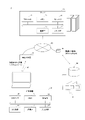
- FIG. 1 is a diagram showing the overall configuration of a management system 1.
- the management system 1 includes multiple user terminals 10 and a server 20 .
- the user terminal 10 and the server 20 are connected via a network 80 so as to be able to communicate with each other.
- Network 80 is configured by a wired or wireless network.
- the management system 1 is connected via a network 80 to a sensing database 30 in a factory where a piping line to be controlled is laid.
- the user terminal 10 is a device operated by each user.
- the user refers to a person who uses the user terminal 10 to control the piping line, which is a function of the management system 1 .
- the user terminal 10 is implemented by a stationary PC (Personal Computer), a laptop PC, or the like.
- the user terminal 10 may be, for example, a mobile terminal such as a tablet compatible with a mobile communication system or a smart phone.
- the user terminal 10 is communicably connected to the server 20 via the network 80 .
- the user terminal 10 is a wireless base station 81 compatible with communication standards such as 5G and LTE (Long Term Evolution), and a wireless LAN (Local Area Network) standard such as IEEE (Institute of Electrical and Electronics Engineers) 802.11. It is connected to the network 80 by communicating with a communication device such as a wireless LAN router 82 .
- the user terminal 10 includes a communication IF (Interface) 12 , an input device 13 , an output device 14 , a memory 15 , a storage section 16 and a processor 19 .
- IF Interface
- the communication IF 12 is an interface for inputting and outputting signals for the user terminal 10 to communicate with an external device.
- the input device 13 is an input device (for example, a keyboard, a touch panel, a touch pad, a pointing device such as a mouse, etc.) for receiving an input operation from a user.
- the output device 14 is an output device (display, speaker, etc.) for presenting information to the user.
- the memory 15 temporarily stores programs and data processed by the programs, and is a volatile memory such as a DRAM (Dynamic Random Access Memory).
- the storage unit 16 is a storage device for storing data, and is, for example, a flash memory or a HDD (Hard Disc Drive).
- the processor 19 is hardware for executing an instruction set described in a program, and is composed of arithmetic units, registers, peripheral circuits, and the like.
- the server 20 is a device that manages information on various devices and piping, information on operating conditions to be controlled, and information on physical models used for arithmetic processing.
- the server 20 accepts input such as an instruction regarding the control of the operating conditions of the pipeline, the current operating state, and the like, from the user who operates the user terminal 10 .
- the server 20 acquires, for example, the operating conditions of each device and the measured values from the sensors, and substitutes these values into the physical model to estimate the maximum throughput. Then, based on the estimated maximum processing amount, various kinds of processing, which will be described later, such as operating reserve capacity, pressure balance, and abnormality detection, are performed.
- the server 20 causes the user terminal 10 to display the processing result.
- the server 20 is a computer connected to the network 80.
- the server 20 includes a communication IF 22 , an input/output IF 23 , a memory 25 , a storage 26 and a processor 29 .
- the communication IF 22 is an interface for inputting and outputting signals for the server 20 to communicate with an external device.
- the input/output IF 23 functions as an interface with an input device for receiving input operations from the user and an output device for presenting information to the user.
- the memory 25 temporarily stores programs and data processed by the programs, and is a volatile memory such as a DRAM (Dynamic Random Access Memory).
- the storage 26 is a storage device for storing data, such as a flash memory or HDD (Hard Disc Drive).
- the processor 29 is hardware for executing an instruction set described in a program, and is composed of arithmetic units, registers, peripheral circuits, and the like.
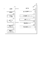
- FIG. 2 is a diagram showing a functional configuration of the server 20 that configures the management system 1.
- the server 20 functions as a communication section 201 , a storage section 202 and a control section 203 .
- the communication unit 201 performs processing for the server 20 to communicate with an external device.
- the storage unit 202 stores data and programs used by the server 20.
- the storage unit 202 stores a process data DB 2021, an equipment data DB 2022, a physical model database 2023, and a calculation result database 2024.
- the process data DB 2021 is a database that stores measurement values acquired by sensors that sense various physical quantities related to the state of fluid flowing through each device. Details will be described later.
- the device data DB 2022 is a database that stores measured values obtained by sensors that sense various physical quantities related to the state of each device. Details will be described later.
- the physical model database 2023 is a database that stores physical models constructed from the operating characteristics (physical characteristics) of each device. Such a physical model will be described by taking a valve as an example. As the flow rate characteristic of the valve, the flow rate of the fluid in the valve is described by a function with the opening degree of the valve as a variable. This function is specified by valve design values. A physical model refers to a function that describes the flow characteristics based on the design values of such valves. A physical model is calculated in advance for each piece of equipment that constitutes the pipeline, and is stored in the physical model database 2023 .
- the computation result database 2024 is a database that stores various computation results in the server 20 . Specifically, the calculation result database 2024 stores calculation results as intermediate processing for using actually measured values for calculation using a physical model, which will be described later. Also, the calculation result database 2024 stores output results from calculations using physical models.
- the control unit 203 includes various modules such as a transmission/reception control module 2031, a measurement value acquisition module 2032, an arithmetic module 2033, a state determination module 2034, and an operation control module 2035. function.
- the transmission/reception control module 2031 controls the process of transmitting/receiving signals from the server 20 to/from an external device according to the communication protocol.
- the measured value acquisition module 2032 acquires the measured value acquired by the sensor from the sensor provided in each device.
- the sensors from which the management system 1 acquires measured values include a first sensor and a second sensor.
- the first sensor measures process data (historian data) indicating the state of the fluid flowing through the piping line under operating conditions.
- process data historian data
- Examples of the first sensor include a flow meter, a thermometer, a pressure gauge, a water level gauge, etc., which are provided in advance in each device.
- the first sensor is built in each device.
- the second sensor is a sensor that measures device data indicating the state of each device under operating conditions.
- the second sensor includes a group of sensors called IoT sensors, which are configured by external modules retrofitted to each device.
- An IoT sensor refers to a sensor that is connected to a network and transmits measurement data to the server 20 .
- the second sensor includes an opening sensor that mechanically measures the opening of the valve.
- the second sensor may not be a sensor group configured by an external module, and may be a sensor provided in advance in each device.
- the calculation module 2033 inputs the acquired sensor measurement values to the physical model stored in the physical model database 2023 to estimate the operating state of the pipeline to be operated.
- the operating conditions estimated by the computing module 2033 include the maximum fluid throughput in the entire pipeline, the operating capacity, the pressure balance of each device, and the like. Details will be described later.
- the state determination module 2034 detects deterioration of the performance of each device based on the maximum processing amount estimated by the calculation module 2033 . Details will be described later.
- the driving control module 2035 determines and proposes driving conditions based on the parameters estimated by the computing module 2033 . Specifically, for example, the operation control module 2035 proposes opening degrees of valves included in each device within the range of the operating capacity. In addition, the operation control module 2035 presents the operating conditions of each device based on the degree of deterioration of the performance of each device. New operating conditions can be reviewed by the operator based on the presented operating conditions.
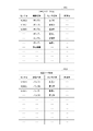
- FIG. 3 is a diagram showing an example of the structure of the database stored by the server 20. As shown in FIG. This figure is only an example, and the structure of the database can be changed arbitrarily. As shown in FIG. 3, each of the records of the process data DB 2021 and the device data DB 2022 includes the item "sensor ID”, the item “device name”, the item “sensor name”, and the item "measurement value”. .
- the item "sensor ID” is information for identifying the sensor.
- the item "equipment name” is information indicating the type of equipment to which each sensor corresponding to the sensor ID is attached.
- the device name stores information on the type of device such as pump A, pump B, pump C, . . . and the name for identifying the device.
- the name indicating the device may be a symbol designated by a predetermined standard or the like, or may be a model number designated by the manufacturer.
- the item "measured value” is a value indicating the measured value obtained by each sensor corresponding to the sensor ID.
- FIG. 4 is a diagram for explaining an outline of control processing in the management system 1. As shown in FIG. As shown in FIG. 4, in a factory, sensing is performed by a first sensor and a second sensor provided in each device. The acquired sensor data are accumulated in the sensing database 30 in chronological order.
- the acquired sensor data is transmitted to the server 20 via a repeater. Some of the sensor data transmitted to the server 20 undergo processing necessary for use in subsequent calculations. Required processing includes, for example, calculation of differential pressure indicating the pressure difference between two points, or calculation of flow rate difference.
- the calculation module 2033 performs estimation calculation processing using the physical model, sensor data, and processed data. Details of the estimation calculation will be described later.
- a result obtained by the estimation calculation is transmitted to the user terminal 10 as a predicted value.
- the predicted value is displayed on the display screen of the user terminal 10 along with the processed value and sensor data.
- the parameter k is a parameter determined by the shape of the pipe and how dirty the inside of the pipe is.
- the parameter k is basically constant regardless of operating conditions, but may change due to internal dirt or clogging. Based on this, the estimation calculation will be described by taking a certain piping system as an example.
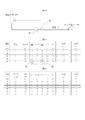
- FIG. 5 is a diagram for explaining the estimation calculation executed by the server 20. As shown in FIG.
- the piping line shown in FIG. 5A is a piping line through which fluid flows from the upper left container toward the lower right tank.
- a pump P and a valve V are provided in the middle of the pipe.
- the following model formula (2) holds as a physical model.
- Formula (2) indicates that the pressure increase by the pump is described by a function with variables of the flow rate F, the density ⁇ , and the pump curve indicated as act.pump curve.
- a pump curve is a function that describes the physical properties of a pump as a function of flow rate. The pump curve is largely determined by the design values of the pump, and gradually changes due to deterioration over time.
- model formula (3) holds as a physical model.
- the pressure reduction by the valve is represented by the flow rate F, the density ⁇ , and the valve opening act.OP(t) denoted as act.OP(t)CV curve, and the valve curve CV curve as variables. It shows that it is described by a function such as The valve opening is a value measured by the second sensor.
- a valve curve is a function that describes the physical properties of a valve as a function of flow rate. The valve curve is largely determined by the design values of the valve, and changes gradually due to deterioration over time. Among the variables input to these model formulas, the pressure, flow rate, density, etc. are measured by the first sensor, and the opening of the valve is measured by the second sensor.
- equations (2) or (3) vary depending on the arrangement and configuration of the equipment in the system, but the outlet (or downstream pressure) is calculated by considering the pressure fluctuations of each equipment such as pipes or pumps to the inlet pressure. It means you can.
- the downstream Pc pressure is obtained by calculating the inlet pressure P1, the pressure increase by the pump, and the pressure decrease in the piping.
- the outlet pressure P2 can be obtained by calculating .
- the pressure at each flow rate can be estimated. For example, by substituting the maximum opening of the valve into the physical model, the maximum flow rate and the pressure balance at that time can be estimated.
- the formula for obtaining the outlet pressure is used, but the inlet pressure may be estimated, and the parameters to be calculated can be changed arbitrarily.
- the physical models shown in formulas (2) and (3) are merely examples, and can be arbitrarily changed according to the structure of the applied pipeline line.
- the loss parameters k1 and k2 are first determined. Loss parameters are determined with reference to historical data.
- the pressure (actual value), the valve opening (actual value), and the flow rate (actual value) are substituted into the physical model that adopts the specified loss parameter, and the predicted value of the tank pressure is calculate. Then, it is checked whether the predicted value of the tank pressure indicates a value close to the measured value of the tank pressure.
- the calculated tank pressure is 195 kPa
- the measured value is 200 kPa. Compared to the measured value, the calculated value is within an error of about 2.5%, so the physical model is appropriate. It is confirmed that
- the loss parameters of the physical model may be inappropriate and that each device may have deteriorated.
- the loss parameter of the physical model is calculated from past operating conditions and measured values, so it is unlikely that deviation will occur in a short period of time. For this reason, when the calculated value and the measured value of the tank pressure deviate, it is considered that each device has deteriorated and its performance has deteriorated. Therefore, it can be estimated that an abnormality has occurred in the device corresponding to the physical characteristics included in the physical model.
- the management system 1 searches for a solution using a genetic algorithm to determine the optimum operating conditions, and estimates the maximum throughput based on the operating conditions. Specifically, as shown in FIG. 5C, the value of the upper limit opening degree set for each valve is set as the valve opening degree. In the example of this figure, the valve opening is set at 85%. Then, the tank pressure is calculated while the flow rate value is changed, and a flow rate value that matches the calculated tank pressure value and the measured tank pressure value is searched for. In the example of this figure, the calculated value and the measured value of the tank pressure match under the operating condition that the flow rate is 180 m 3 /h. Therefore, the maximum throughput is estimated to be 180 m 3 /h (broken line).
- FIG. 6 is a diagram showing the operation flow of the management system 1.
- the server 20 acquires sensor measurement values from the sensing database 30 (step S100).
- the measured value acquisition module 2032 of the server 20 acquires the sensor measured value transmitted from the repeater of the sensing database 30 via the transmission/reception control module 2031 .
- Sensor readings include process data and equipment data.
- the server 20 processes the sensor measurement values (step S101). Specifically, the calculation module 2033 of the server 20 performs calculation processing necessary for subsequent calculations, such as differential pressure calculation and flow rate difference calculation, on the sensor measurement values.
- the server 20 estimates the maximum amount of processing (step S102). Specifically, the arithmetic module 2033 of the server 20 substitutes the measured value and the measured value after processing into the physical model to calculate and estimate the maximum processing amount. Calculation of the maximum amount of processing may be performed by solution search using a genetic algorithm, as described above. If the genetic algorithm is not used, the response aspect method may be used for solution search. In this case, a certain amount of solution candidates are prepared in advance, and an appropriate solution is searched for by substituting by trial and error.
- the server 20 estimates the remaining driving capacity (step S103). Specifically, the arithmetic module 2033 of the server 20 estimates how much operating capacity is available at the present time by obtaining a difference between the estimated maximum processing amount and the current processing amount.
- the server 20 estimates the pressure balance (step S104). Specifically, the arithmetic module 2033 of the server 20 determines whether the pressure balance for confirming the pressure balance of the piping line is normal, for example, by comparing it with a predetermined threshold value set in advance, based on the pressure measured by the sensor. You can judge. If there is an abnormality in the pressure balance, it can be detected that there is a problem somewhere in the pipeline.
- the server 20 determines operating conditions (step S105). Specifically, the computing module 2033 of the server 20 determines the optimum operating conditions based on the results estimated by the computing module 2033 . For example, a valve opening determined based on the estimated maximum throughput can be set as an operating condition. Further, the estimated optimum operating conditions can be used to examine subsequent operating conditions.
- the server 20 displays an output screen (step S106). Specifically, the transmission/reception control module 2031 of the server 20 outputs to the user terminal 10 an output screen regarding the operating state and the predicted value. Thus, the processing of the management system 1 ends.
- FIG. 7 is a diagram showing an example of an output screen in the management system 1. As shown in FIG. This figure is only an example, and the output screen can be changed arbitrarily. As shown in FIG. 7, the estimated maximum processing amount is displayed on the output screen of the user terminal 10 (symbol A). By checking the maximum throughput, it is possible to check how much margin there is in the operation of the pipeline. Also. The remaining driving capacity may be displayed at the same time.
- the output screen displays the actual measured value (symbol B) of the pressure sensor and the estimated predicted value (symbol C) are displayed.
- the output screen displays the actual operating state and the predicted value calculated by the estimation calculation. By comparing these values, it is possible to confirm the validity of the physical model used in the arithmetic processing.
- the measured value of the opening of the valve (symbol D) and the estimated predicted value (symbol E) are displayed.
- the predicted valve opening may be set in the operating conditions in order to achieve the estimated maximum throughput.
- FIG. 8 is a diagram showing an outline of control processing of the management system 1 according to the modification.
- a process of searching the parameters of the physical model using the immediately preceding measured values and the goal seek used, and updating the physical model using the estimated optimum solution is performed. Updating the physical model by such an estimation operation will be described with reference to FIG.
- FIG. 9 is a diagram for explaining the estimation calculation executed by the server 20 of the management system 1 according to Modification 1. As shown in FIG.
- next data time t+1
- the next data is substituted into the physical model to which the previously obtained parameter k value is input, and the valve opening degree Check the value of the flow rate when is the allowable maximum value.
- a genetic algorithm is used to search for a flow rate solution that matches the measured value of the tank pressure with the predicted value of the tank pressure.
- the maximum throughput is estimated to be 180 m 3 /h, as indicated by the symbol *.
- the device data acquired by the second sensor is explained by taking the valve opening degree as an example, but it is not limited to such an aspect.
- the device data acquired by the second sensor can be arbitrarily changed as long as it is data indicating the state of behavior of each device.
- the valve opening is estimated as the optimum operating condition, but the present invention is not limited to this aspect.
- the operations control module 2035 may determine the optimum pumping pressure to the tanks contained in each piece of equipment from the estimated maximum throughput.
- the pumping pressure can be obtained by estimating the pressure at the tank inlet and converting it to the liquid level in the tank.
- the state determination module 2034 detects malfunction of each device from the pressure balance, but it is not limited to such a mode.
- the state determination module 2034 may identify a bottleneck in the entire system among the devices that make up the pipeline. In this case, by setting a plurality of evaluation sections for the pipeline to be evaluated, building a physical model for each section, and comparing the estimated maximum throughput in each section, You can identify bottlenecks. Also, by comparing the estimated maximum throughput in each section, it is possible to estimate the balance of the maximum throughput in a plurality of mutually connected pipelines.
- a management system comprising a processor, for managing the operating conditions of a fluid processing piping line, comprising: The processor a step of acquiring measured values of sensors provided in each device constituting the pipeline; A management system that executes a step of estimating the maximum throughput of fluid in the entire piping line to be operated by inputting the obtained sensor measurement values into a physical model constructed from the physical characteristics of each piece of equipment.
- the sensor a first sensor that measures process data indicating the state of the fluid flowing through the pipeline;
- a management system according to (Appendix 1), further comprising: a second sensor that measures device data indicating the state of each device.
- (Appendix 4) The processor Based on the estimated maximum throughput, calculate the operating capacity of the pipeline, The management system according to any one of (Appendix 1) to (Appendix 3), wherein the step of determining the operating conditions of the pipeline is executed within the range of the calculated operating margin.
- (Appendix 6) The processor The management system according to any one of (Appendix 1) to (Appendix 5), wherein the operating status of the entire pipeline or each device is displayed based on the estimated maximum throughput.
- (Appendix 7) The processor 6.
- the management system according to any one of (Appendix 1) to (Appendix 6), wherein the pressure balance across the pipeline is estimated based on the estimated maximum throughput.
- (Appendix 9) The processor The management system according to any one of (Appendix 1) to (Appendix 8), wherein the performance of each device is evaluated based on the estimated maximum processing amount, and deterioration of the performance of each device is detected.
- (Appendix 11) The processor 10.
- the management system according to any one of (Appendix 1) to (Appendix 10), which executes a step of identifying a bottleneck portion in the entire system among the devices constituting the pipeline.
- (Appendix 12) The processor 12.
- the management system according to any one of (Appendix 1) to (Appendix 11), which estimates a balance of maximum throughput in a plurality of pipelines connected to each other.
- (Appendix 13) In the step of estimating the maximum throughput, The management system according to any one of (Appendix 1) to (Appendix 12), wherein optimal operating conditions are determined by searching for a solution using a genetic algorithm, and the maximum throughput is estimated based on the operating conditions. .
- a management program comprising a processor, for managing the operating conditions of a fluid processing piping line, comprising: to the processor, a step of acquiring measured values of sensors provided in each device under operating conditions; A step of estimating the maximum throughput of fluid in the entire pipeline to be operated by inputting the obtained sensor measurement values into a physical model constructed from the physical characteristics of each device that constitutes the pipeline; Management program to run.
- Management System 10 User Terminal 20 Server 22 Communication IF 23 input/output IF 25 memory 26 storage 29 processor 201 communication unit 202 storage unit 203 control unit 2031 transmission/reception control module 2032 measurement value acquisition module 2033 calculation module 2034 state determination module 2035 operation control module 30 sensing database 80 network
Landscapes
- Engineering & Computer Science (AREA)
- General Engineering & Computer Science (AREA)
- Mechanical Engineering (AREA)
- Physics & Mathematics (AREA)
- Acoustics & Sound (AREA)
- Automation & Control Theory (AREA)
- Quality & Reliability (AREA)
- General Physics & Mathematics (AREA)
- Manufacturing & Machinery (AREA)
- Health & Medical Sciences (AREA)
- Public Health (AREA)
- Water Supply & Treatment (AREA)
- General Factory Administration (AREA)
- Pipeline Systems (AREA)
- Communication Control (AREA)
- Feedback Control In General (AREA)
- Testing And Monitoring For Control Systems (AREA)
Abstract
Description
一方、化学プラントのように、生成物をタンクに貯留する配管ラインの場合には、タンク内の貯留量や様々な機器の経時的な圧力バランスの変化、前工程の供給量等、配管ラインのそれぞれの分岐ラインの処理量に対して影響を与える因子が多岐に渡り、運転の状態により処理能力が変動する。
このような運転の状態の変化により変動する最大処理量を、運転条件などに基づいて正確に把握することが生産性最大化を維持する場合に特に求められていた。
以下、配管ラインの管理システム1(以下、単に管理システム1)という。この管理システム1は、例えば、LNG(Liquefied Natural Gas:液化天然ガス)プラントや石油化学プラントのように、化学反応による様々な生産工程を経由して化学製品を製造するための設備群において、各種の流体を処理する配管ラインの運転条件の制御を行うためのシステムである。なお、管理システム1は、下水設備や浄水設備のような、大規模な化学反応を伴わずに、流体を処理する設備に用いられてもよい。
次に、管理システム1の全体構成について説明する。図1は、管理システム1の全体の構成を示す図である。
図1に示すように、管理システム1は、複数のユーザ端末10と、サーバ20と、を含む。ユーザ端末10とサーバ20とは、ネットワーク80を介して相互に通信可能に接続されている。ネットワーク80は、有線または無線ネットワークにより構成される。
管理システム1には、ネットワーク80を介して制御対象となる配管ラインが敷設された工場におけるセンシングデータベース30が接続されている。
図1に示すように、ユーザ端末10は、通信IF(Interface)12と、入力装置13と、出力装置14と、メモリ15と、記憶部16と、プロセッサ19とを備える。
入力装置13は、ユーザからの入力操作を受け付けるための入力装置(例えば、キーボードや、タッチパネル、タッチパッド、マウス等のポインティングデバイス等)である。
メモリ15は、プログラム、及び、プログラム等で処理されるデータ等を一時的に記憶するためのものであり、例えばDRAM(Dynamic Random Access Memory)等の揮発性のメモリである。
プロセッサ19は、プログラムに記述された命令セットを実行するためのハードウェアであり、演算装置、レジスタ、周辺回路などにより構成される。
サーバ20は、ユーザ端末10を操作するユーザから、配管ラインの運転条件の制御に関する指示・現在の運転状態等の入力を受け付ける。
入出力IF23は、ユーザからの入力操作を受け付けるための入力装置、及び、ユーザに対し情報を提示するための出力装置とのインタフェースとして機能する。
ストレージ26は、データを保存するための記憶装置であり、例えばフラッシュメモリ、HDD(Hard Disc Drive)である。
プロセッサ29は、プログラムに記述された命令セットを実行するためのハードウェアであり、演算装置、レジスタ、周辺回路などにより構成される。
次に、サーバ20の機能的な構成について説明する。
図2は、管理システム1を構成するサーバ20の機能的な構成を示す図である。図2に示すように、サーバ20は、通信部201と、記憶部202と、制御部203としての機能を発揮する。
演算モジュール2033が推定する運転状態としては、配管ライン全体における流体の最大処理量、運転余力、各機器の圧力バランス等が含まれる。詳細は後述する。
次に、サーバ20が記憶するデータベースの構造の一例について説明する。
図3は、サーバ20が記憶するデータベースの構造の一例を示す図である。なお、この図はあくまで一例であり、データベースの構造は任意に変更することができる。
図3に示すように、プロセスデータDB2021および機器データDB2022のレコードのそれぞれは、項目「センサID」と、項目「機器名称」と、項目「センサ名称」と、項目「計測値」と、を含む。
以下、管理システム1における制御処理の概要について説明する。
図4は、管理システム1における制御処理の概要を説明する図である。
図4に示すように、工場では、各機器に設けられた第1センサおよび第2センサにより、センシングが行われる。取得されたセンサデータは、時系列に沿ってセンシングデータベース30に蓄積される。
以下、物理モデルを用いたパラメータの推定処理の概要について説明する。
例えば、配管における流体の圧力損失は、以下のモデル式(1)により記述されることが知られている。

これを踏まえて、ある系の配管システムを例に挙げて、推定演算を説明する。図5はサーバ20が実行する推定演算を説明する図である。
この場合、物理モデルとして、以下のモデル式(2)が成り立つ。
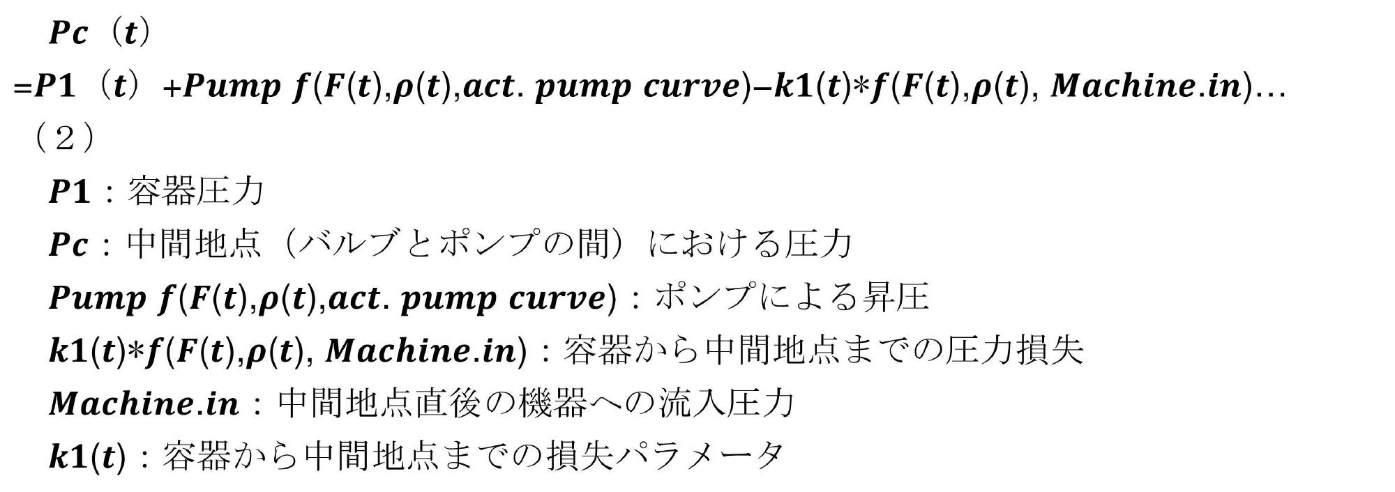
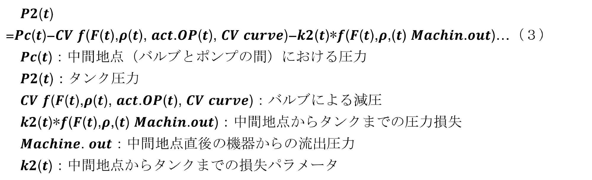
そして、これらのモデル式に入力される変数のうち、圧力、流量、密度等は、第1センサにより計測され、バルブの開度は第2センサにより計測される。
式(2)では、入口圧力P1とポンプによる昇圧、配管による圧力減少を計算することで下流Pcの圧力を求めており、式(3)では、入口圧力Pcとバルブによる減圧と配管による圧力減少を計算することで出口圧力P2を求めることができる。
以下、管理システム1の動作について説明する。図6は、管理システム1の動作フローを示す図である。
図6に示すように、サーバ20は、センシングデータベース30からセンサの計測値を取得する(ステップS100)。具体的には、サーバ20の計測値取得モジュール2032は、送受信制御モジュール2031を介して、センシングデータベース30の中継器から送信されたセンサの計測値を取得する。センサの計測値には、プロセスデータおよび機器データが含まれている。
以上により、管理システム1の処理が終了する。
次に、管理システム1からの出力画面の例について説明する。図7は、管理システム1における出力画面の例を示す図である。なお、あくまでこの図は一例であり、出力画面は任意に変更することができる。
図7に示すように、ユーザ端末10における出力画面には、推定された最大処理量が表示されている(符号A)。最大処理量を確認することで、配管ラインの運転にどの程度余裕があるかを確認することができる。また。運転余力を同時に表示してもよい。
次に、管理システム1の変形例について説明する。図8は、変形例に係る管理システム1の制御処理の概要を示す図である。変形例に係る管理システム1では、直前の実測値と用いたゴールシークにより、物理モデルのパラメータを探索し、推定された最適な解を用いて物理モデルを更新する処理が行われる。このような推定演算による物理モデルの更新について、図9を用いて説明する。図9は、変形例1に係る管理システム1のサーバ20が実行する推定演算を説明する図である。
その他の変形例について説明する。
上記実施形態では、第2センサが取得する機器データとして、バルブ開度を例に挙げて説明したが、このような態様に限られない。第2センサが取得する機器データは、各機器の挙動に関する状態を示すデータであれば任意に変更することができる。
また、各処理は、矛盾しない範囲で処理の順番を変更することができる。
プロセッサを備え、流体を処理する配管ラインの運転条件を管理する管理システムであって、
プロセッサは、
配管ラインを構成する各機器に設けられたセンサの計測値を取得するステップと、
各機器それぞれの物理特性から構築された物理モデルに、取得したセンサの計測値を入力することにより、運転を行う配管ライン全体における流体の最大処理量を推定するステップと、を実行する管理システム。
センサは、
配管ラインを流れる流体の状態を示すプロセスデータを計測する第1センサと、
各機器の状態を示す機器データを計測する第2センサと、を含む(付記1)に記載の管理システム。
第2センサが取得する機器データには、各機器に含まれるバルブの開度を機械的に計測したバルブ開度の実測値が含まれる、(付記2)に記載の管理システム。
プロセッサは、
推定された最大処理量に基づき、配管ラインの運転余力を算出し、
算出された運転余力の範囲内で、配管ラインの運転条件を決定するステップを実行する、(付記1)から(付記3)のいずれかに記載の管理システム。
運転条件を決定するステップでは、
算出された運転余力の範囲内で、各機器に含まれるバルブの開度を決定する、(付記4)に記載の管理システム。
プロセッサは、
推定した最大処理量に基づいて、配管ライン全体または各機器の運転状態を表示する、(付記1)から(付記5)のいずれかに記載の管理システム。
プロセッサは、
推定した最大処理量に基づいて、配管ライン全体の圧力バランスを推定する、(付記1)から(付記6)のいずれかに記載の管理システム。
プロセッサは、
推定した最大処理量に基づいて、
各機器に含まれるタンクへの圧送圧力を特定するステップを実行する、(付記1)から(付記7)のいずれかに記載の管理システム。
プロセッサは、
推定した最大処理量に基づいて、各機器の性能を評価し、各機器の性能の劣化を検出する、(付記1)から(付記8)のいずれかに記載の管理システム。
プロセッサは、
蓄積された過去の計測値から、物理モデルを修正する、(付記1)から(付記9)のいずれかに記載の管理システム。
プロセッサは、
配管ラインを構成する機器のうち、系全体におけるボトルネックとなる部分を特定するステップを実行する、(付記1)から(付記10)のいずれかに記載の管理システム。
プロセッサは、
互いに連結される複数の配管ラインにおける最大処理量のバランスを推定する、(付記1)から(付記11)のいずれかに記載の管理システム。
最大処理量を推定するステップにおいて、
遺伝的アルゴリズムを用いた解の探索により、最適な運転条件を決定し、当該運転条件に基づいて、最大処理量を推定する、(付記1)から(付記12)のいずれかに記載の管理システム。
プロセッサを備える管理システムが実行し、流体を処理する配管ラインの運転条件を管理する管理方法であって、
プロセッサは、
配管ラインを構成する各機器に設けられたセンサの計測値を取得するステップと、
各機器それぞれの物理特性から構築された物理モデルに、取得したセンサの計測値を入力することにより、運転を行う配管ライン全体における流体の最大処理量を推定するステップと、を実行する管理方法。
プロセッサを備え、流体を処理する配管ラインの運転条件を管理する管理プログラムであって、
プロセッサに、
運転条件における各機器に設けられたセンサの計測値を取得するステップと、
配管ラインを構成する各機器それぞれの物理特性から構築された物理モデルに、取得したセンサの計測値を入力することにより、運転を行う配管ライン全体における流体の最大処理量を推定するステップと、を実行させる管理プログラム。
10 ユーザ端末
20 サーバ
22 通信IF
23 入出力IF
25 メモリ
26 ストレージ
29 プロセッサ
201 通信部
202 記憶部
203 制御部
2031 送受信制御モジュール
2032 計測値取得モジュール
2033 演算モジュール
2034 状態判定モジュール
2035 運転制御モジュール
30 センシングデータベース
80 ネットワーク
Claims (15)
- プロセッサを備え、流体を処理する配管ラインの運転条件を管理する管理システムであって、
前記プロセッサは、
前記配管ラインを構成する各機器に設けられたセンサの計測値を取得するステップと、
前記各機器それぞれの物理特性から構築された物理モデルに、取得した前記センサの計測値を入力することにより、運転を行う前記配管ライン全体における流体の最大処理量を推定するステップと、を実行する管理システム。 - 前記センサは、
前記配管ラインを流れる流体の状態を示すプロセスデータを計測する第1センサと、
前記各機器の状態を示す機器データを計測する第2センサと、を含む請求項1に記載の管理システム。 - 前記第2センサが取得する機器データには、前記各機器に含まれるバルブの開度を機械的に計測したバルブ開度の実測値が含まれる、請求項2に記載の管理システム。
- 前記プロセッサは、
推定された前記最大処理量に基づき、前記配管ラインの運転余力を算出し、
算出された前記運転余力の範囲内で、前記配管ラインの運転条件を決定するステップを実行する、請求項1から3のいずれか1項に記載の管理システム。 - 前記運転条件を決定するステップでは、
算出された前記運転余力の範囲内で、前記各機器に含まれるバルブの開度を決定する、請求項4に記載の管理システム。 - 前記プロセッサは、
推定した前記最大処理量に基づいて、配管ライン全体または各機器の運転状態を表示する、請求項1から5のいずれか1項に記載の管理システム。 - 前記プロセッサは、
推定した前記最大処理量に基づいて、前記配管ライン全体の圧力バランスを推定する、請求項1から6のいずれか1項に記載の管理システム。 - 前記プロセッサは、
推定した前記最大処理量に基づいて、
前記各機器に含まれるタンクへの圧送圧力を特定するステップを実行する、請求項1から7のいずれか1項に記載の管理システム。 - 前記プロセッサは、
推定した前記最大処理量に基づいて、前記各機器の性能を評価し、各機器の性能の劣化を検出する、請求項1から8のいずれか1項に記載の管理システム。 - 前記プロセッサは、
蓄積された過去の前記計測値から、前記物理モデルを修正する、請求項1から9のいずれか1項に記載の管理システム。 - 前記プロセッサは、
前記配管ラインを構成する機器のうち、系全体におけるボトルネックとなる部分を特定するステップを実行する、請求項1から10のいずれか1項に記載の管理システム。 - 前記プロセッサは、
互いに連結される複数の前記配管ラインにおける前記最大処理量のバランスを推定する、請求項1から11のいずれか1項に記載の管理システム。 - 前記最大処理量を推定するステップにおいて、
遺伝的アルゴリズムを用いた解の探索により、最適な運転条件を決定し、当該運転条件に基づいて、前記最大処理量を推定する、請求項1から12のいずれか1項に記載の管理システム。 - プロセッサを備える管理システムが実行し、流体を処理する配管ラインの運転条件を管理する管理方法であって、
前記プロセッサは、
前記配管ラインを構成する各機器に設けられたセンサの計測値を取得するステップと、
前記各機器それぞれの物理特性から構築された物理モデルに、取得した前記センサの計測値を入力することにより、運転を行う前記配管ライン全体における流体の最大処理量を推定するステップと、を実行する管理方法。 - プロセッサを備え、流体を処理する配管ラインの運転条件を管理する管理プログラムであって、
前記プロセッサに、
前記運転条件における前記各機器に設けられたセンサの計測値を取得するステップと、
前記配管ラインを構成する各機器それぞれの物理特性から構築された物理モデルに、取得した前記センサの計測値を入力することにより、運転を行う前記配管ライン全体における流体の最大処理量を推定するステップと、を実行させる管理プログラム。
Priority Applications (6)
| Application Number | Priority Date | Filing Date | Title |
|---|---|---|---|
| PCT/JP2021/026199 WO2023286141A1 (ja) | 2021-07-13 | 2021-07-13 | 管理システム、管理方法、および管理プログラム |
| AU2021455544A AU2021455544A1 (en) | 2021-07-13 | 2021-07-13 | Management system, management method, and management program |
| JP2022540824A JP7201882B1 (ja) | 2021-07-13 | 2021-07-13 | 管理システム、管理方法、および管理プログラム |
| TW111125863A TWI824613B (zh) | 2021-07-13 | 2022-07-11 | 管理系統、管理方法及管理程式 |
| JP2022205063A JP2023024874A (ja) | 2021-07-13 | 2022-12-22 | 管理システム、管理方法、および管理プログラム |
| US18/187,016 US12578065B2 (en) | 2021-07-13 | 2023-03-21 | Management system and management method, and computer-readable storage medium |
Applications Claiming Priority (1)
| Application Number | Priority Date | Filing Date | Title |
|---|---|---|---|
| PCT/JP2021/026199 WO2023286141A1 (ja) | 2021-07-13 | 2021-07-13 | 管理システム、管理方法、および管理プログラム |
Related Child Applications (1)
| Application Number | Title | Priority Date | Filing Date |
|---|---|---|---|
| US18/187,016 Continuation US12578065B2 (en) | 2021-07-13 | 2023-03-21 | Management system and management method, and computer-readable storage medium |
Publications (1)
| Publication Number | Publication Date |
|---|---|
| WO2023286141A1 true WO2023286141A1 (ja) | 2023-01-19 |
Family
ID=84817444
Family Applications (1)
| Application Number | Title | Priority Date | Filing Date |
|---|---|---|---|
| PCT/JP2021/026199 Ceased WO2023286141A1 (ja) | 2021-07-13 | 2021-07-13 | 管理システム、管理方法、および管理プログラム |
Country Status (5)
| Country | Link |
|---|---|
| US (1) | US12578065B2 (ja) |
| JP (2) | JP7201882B1 (ja) |
| AU (1) | AU2021455544A1 (ja) |
| TW (1) | TWI824613B (ja) |
| WO (1) | WO2023286141A1 (ja) |
Families Citing this family (2)
| Publication number | Priority date | Publication date | Assignee | Title |
|---|---|---|---|---|
| JP2025060087A (ja) * | 2023-09-29 | 2025-04-10 | 株式会社日立産機システム | 圧縮機制御システムおよび圧縮機制御方法 |
| CN117647963B (zh) * | 2024-01-29 | 2024-04-09 | 四川速聚智联科技有限公司 | 用于天然气方井池的排液智能控制方法及系统 |
Citations (4)
| Publication number | Priority date | Publication date | Assignee | Title |
|---|---|---|---|---|
| JP2001209405A (ja) * | 2000-01-24 | 2001-08-03 | Hitachi Ltd | プラントの制御方法および装置 |
| JP2004310674A (ja) * | 2003-04-10 | 2004-11-04 | Toshiba Corp | プラント運用方案作成支援装置 |
| JP2011196599A (ja) * | 2010-03-18 | 2011-10-06 | Mitsubishi Electric Corp | 空気調和機および空気調和機の制御方法 |
| JP2015176219A (ja) * | 2014-03-13 | 2015-10-05 | 株式会社東芝 | 縮退運転支援装置、及び縮退運転支援方法 |
Family Cites Families (19)
| Publication number | Priority date | Publication date | Assignee | Title |
|---|---|---|---|---|
| JP2601895B2 (ja) | 1989-01-11 | 1997-04-16 | 株式会社東芝 | 配水管網制御装置 |
| JP3147586B2 (ja) | 1993-05-21 | 2001-03-19 | 株式会社日立製作所 | プラントの監視診断方法 |
| JPH07121230A (ja) * | 1993-10-26 | 1995-05-12 | Toshiba Corp | プラント状態予測装置 |
| JP3561800B2 (ja) * | 2000-06-28 | 2004-09-02 | 株式会社クボタ | 排水管路設計検証方法、排水管路設計検証装置、コンピュータプログラム及び記録媒体 |
| JP2003150233A (ja) * | 2001-11-12 | 2003-05-23 | Hitachi Ltd | プラントの性能劣化状態評価方法と性能劣化状態評価装置 |
| JP2004217800A (ja) * | 2003-01-15 | 2004-08-05 | Idemitsu Kosan Co Ltd | 石油製品の製造方法及びその製造装置 |
| JP4546332B2 (ja) | 2005-06-09 | 2010-09-15 | 株式会社日立製作所 | 運転支援装置および運転支援方法 |
| JP4814166B2 (ja) * | 2007-07-24 | 2011-11-16 | 株式会社山武 | 流量制御バルブの情報表示装置および情報表示方法 |
| WO2011104419A1 (en) * | 2010-02-26 | 2011-09-01 | Metso Automation Oy | Performance monitoring of a pump-valve system |
| JP5690650B2 (ja) * | 2011-05-09 | 2015-03-25 | 新日鉄住金エンジニアリング株式会社 | 地盤熱特性解析方法及び装置、土壌熱源ヒートポンプシステムの運転調整方法及び装置、並びにプログラム |
| US10437265B2 (en) * | 2014-04-29 | 2019-10-08 | Metso Flow Control Oy | Performance monitoring of pump-valve system |
| US9897259B1 (en) * | 2017-04-18 | 2018-02-20 | Air Products And Chemicals, Inc. | Control system in a gas pipeline network to satisfy pressure constraints |
| US9890908B1 (en) * | 2017-04-18 | 2018-02-13 | Air Products And Chemicals, Inc. | Control system in a gas pipeline network to increase capacity factor |
| JP6718911B2 (ja) * | 2018-05-21 | 2020-07-08 | 三菱日立パワーシステムズ株式会社 | モデル作成方法、プラントの運転支援方法及びモデル作成装置 |
| JP6529690B1 (ja) | 2018-06-08 | 2019-06-12 | 千代田化工建設株式会社 | 支援装置、学習装置、及びプラント運転条件設定支援システム |
| JP2020052821A (ja) * | 2018-09-27 | 2020-04-02 | 株式会社ジェイテクト | 劣化判定装置および劣化判定システム |
| JP2020126404A (ja) | 2019-02-04 | 2020-08-20 | アズビル株式会社 | 乾き度管理装置 |
| US11853032B2 (en) * | 2019-05-09 | 2023-12-26 | Aspentech Corporation | Combining machine learning with domain knowledge and first principles for modeling in the process industries |
| JP7312656B2 (ja) * | 2019-09-24 | 2023-07-21 | 株式会社Screenホールディングス | 基板処理装置 |
-
2021
- 2021-07-13 WO PCT/JP2021/026199 patent/WO2023286141A1/ja not_active Ceased
- 2021-07-13 JP JP2022540824A patent/JP7201882B1/ja active Active
- 2021-07-13 AU AU2021455544A patent/AU2021455544A1/en not_active Abandoned
-
2022
- 2022-07-11 TW TW111125863A patent/TWI824613B/zh active
- 2022-12-22 JP JP2022205063A patent/JP2023024874A/ja active Pending
-
2023
- 2023-03-21 US US18/187,016 patent/US12578065B2/en active Active
Patent Citations (4)
| Publication number | Priority date | Publication date | Assignee | Title |
|---|---|---|---|---|
| JP2001209405A (ja) * | 2000-01-24 | 2001-08-03 | Hitachi Ltd | プラントの制御方法および装置 |
| JP2004310674A (ja) * | 2003-04-10 | 2004-11-04 | Toshiba Corp | プラント運用方案作成支援装置 |
| JP2011196599A (ja) * | 2010-03-18 | 2011-10-06 | Mitsubishi Electric Corp | 空気調和機および空気調和機の制御方法 |
| JP2015176219A (ja) * | 2014-03-13 | 2015-10-05 | 株式会社東芝 | 縮退運転支援装置、及び縮退運転支援方法 |
Also Published As
| Publication number | Publication date |
|---|---|
| US20230280000A1 (en) | 2023-09-07 |
| JP7201882B1 (ja) | 2023-01-10 |
| JPWO2023286141A1 (ja) | 2023-01-19 |
| US12578065B2 (en) | 2026-03-17 |
| JP2023024874A (ja) | 2023-02-17 |
| AU2021455544A1 (en) | 2023-10-26 |
| TW202303305A (zh) | 2023-01-16 |
| TWI824613B (zh) | 2023-12-01 |
Similar Documents
| Publication | Publication Date | Title |
|---|---|---|
| JP5037447B2 (ja) | ガス搬送システムを管理するための報告機能付調整器 | |
| CA2988960C (en) | Control system in a gas pipeline network to increase capacity factor | |
| Andrade et al. | Virtual flow metering of production flow rates of individual wells in oil and gas platforms through data reconciliation | |
| CN115587640B (zh) | 智慧燃气管道清管安全管理方法、物联网系统及介质 | |
| JP2023024874A (ja) | 管理システム、管理方法、および管理プログラム | |
| CN115982918B (zh) | 阻力特性辨识方法、装置、设备及存储介质 | |
| Ruiz-Cárcel et al. | Canonical variate analysis for performance degradation under faulty conditions | |
| CN119043466A (zh) | 一种流量计校准方法和装置 | |
| US10429828B2 (en) | Plant simulation device and plant simulation method with first parameter adjustable at start and second parameter adjustable during operation of the plant | |
| WO2023091648A1 (en) | Method and system for predictive flow measurement at in-plant piping | |
| US20240201001A1 (en) | Integrated machine learning platform to capture multiphase virtual flow rates and diagnostic measures | |
| US11867546B2 (en) | Method and system for wireless flow sensing of manually operated valves | |
| US20230383633A1 (en) | Machine-learned based real-time virtual gas metering | |
| CN118090043B (zh) | 一种压力表异常状态定位分析方法、系统、终端及介质 | |
| US20240393157A1 (en) | Methods and systems for enhancing well flow rate signal | |
| JP6874847B2 (ja) | 状態分析装置、状態分析方法及びプログラム | |
| CN116773154B (zh) | 用于监控工艺技术设施的部件的状态的方法和装置 | |
| van der Bent et al. | The Application of Data Validation and Reconciliation to Upstream Production Measurement Integration and Surveillance–Field Study | |
| JP7685429B2 (ja) | 設備情報検索システム、設備情報検索方法、および制御性能診断システム | |
| JPWO2015087378A1 (ja) | 水道施設網の異常検知装置及び異常検知方法 | |
| CN118274248B (zh) | 储气站数据自动测控装置、系统及方法 | |
| US20240241511A1 (en) | Computer System and Method of Building and Deploying a Customized Plant Asset Failure Prediction Engine | |
| US11454529B2 (en) | Augmented flowmeter with a system for simulating fluid parameters | |
| Krasnov et al. | Automatic System for Indirect Assessment of Gas Flow in Gas Collection Systems | |
| Andrianova et al. | Development of a hydrate-free operating mode model for gas lift wells |
Legal Events
| Date | Code | Title | Description |
|---|---|---|---|
| ENP | Entry into the national phase |
Ref document number: 2022540824 Country of ref document: JP Kind code of ref document: A |
|
| 121 | Ep: the epo has been informed by wipo that ep was designated in this application |
Ref document number: 21950084 Country of ref document: EP Kind code of ref document: A1 |
|
| WWE | Wipo information: entry into national phase |
Ref document number: AU2021455544 Country of ref document: AU Ref document number: 2021455544 Country of ref document: AU |
|
| WWE | Wipo information: entry into national phase |
Ref document number: P6002755/2023 Country of ref document: AE |
|
| ENP | Entry into the national phase |
Ref document number: 2021455544 Country of ref document: AU Date of ref document: 20210713 Kind code of ref document: A |
|
| WWE | Wipo information: entry into national phase |
Ref document number: 523451053 Country of ref document: SA |
|
| WWE | Wipo information: entry into national phase |
Ref document number: 11202307496X Country of ref document: SG |
|
| NENP | Non-entry into the national phase |
Ref country code: DE |
|
| 122 | Ep: pct application non-entry in european phase |
Ref document number: 21950084 Country of ref document: EP Kind code of ref document: A1 |
|
| WWE | Wipo information: entry into national phase |
Ref document number: 523451053 Country of ref document: SA |
|
| WWR | Wipo information: refused in national office |
Ref document number: 523451053 Country of ref document: SA |