WO2023286117A1 - モータ、送風機および空気調和装置 - Google Patents
モータ、送風機および空気調和装置 Download PDFInfo
- Publication number
- WO2023286117A1 WO2023286117A1 PCT/JP2021/026107 JP2021026107W WO2023286117A1 WO 2023286117 A1 WO2023286117 A1 WO 2023286117A1 JP 2021026107 W JP2021026107 W JP 2021026107W WO 2023286117 A1 WO2023286117 A1 WO 2023286117A1
- Authority
- WO
- WIPO (PCT)
- Prior art keywords
- magnetic
- teeth
- tooth
- axis
- stator
- Prior art date
- Legal status (The legal status is an assumption and is not a legal conclusion. Google has not performed a legal analysis and makes no representation as to the accuracy of the status listed.)
- Ceased
Links
Images






Classifications
-
- H—ELECTRICITY
- H02—GENERATION; CONVERSION OR DISTRIBUTION OF ELECTRIC POWER
- H02K—DYNAMO-ELECTRIC MACHINES
- H02K1/00—Details of the magnetic circuit
- H02K1/06—Details of the magnetic circuit characterised by the shape, form or construction
- H02K1/12—Stationary parts of the magnetic circuit
- H02K1/14—Stator cores with salient poles
Definitions
- the present disclosure relates to motors, blowers, and air conditioners.
- a motor used for a blower or the like of an air conditioner has a rotor having a permanent magnet and a stator surrounding the rotor (see Patent Document 1, for example).
- the present disclosure has been made to solve the above problems, and aims to reduce noise.
- the motor of the present disclosure has a rotor rotatable about an axis and a stator surrounding the rotor from the outside in a radial direction about the axis, and the direction of the axis intersects the direction of gravity.
- the stator has an annular core-back extending in a circumferential direction around the axis, and a plurality of teeth extending radially inward from the core-back.
- the plurality of teeth includes a first tooth and a second tooth that are circumferentially adjacent to each other below the axis.
- a first non-magnetic portion is provided between a radially outer portion of the first tooth and a radially outer portion of the second tooth.
- the first non-magnetic portion provided in the core-back of the stator enables magnetic attraction between the rotor and stator. Forces can be evened out. As a result, whirling of the rotor can be suppressed and noise can be reduced.
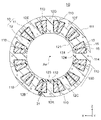
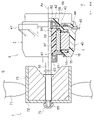
- FIG. 2 is a longitudinal sectional view showing the outdoor unit of Embodiment 1; 1 is a vertical cross-sectional view showing a blower according to Embodiment 1; FIG. 2 is a cross-sectional view showing the motor of Embodiment 1; FIG. 2 is a cross-sectional view showing the rotor of Embodiment 1; FIG. 2 is a cross-sectional view showing the stator of Embodiment 1; FIG. 4A and 4B are diagrams (A) and (B) showing split cores of the stator of the first embodiment; FIG. 4 is a schematic diagram showing the flow of magnetic flux in the stator of Embodiment 1. FIG. FIG. FIG.
- FIG. 6 is a cross-sectional view showing a stator according to Embodiment 2;
- FIG. 11 is a cross-sectional view showing a stator according to Embodiment 3;
- FIG. 11 is a cross-sectional view showing a stator according to Embodiment 4;
- FIG. 11 is a cross-sectional view showing a stator according to Embodiment 5;
- FIG. 11 is a cross-sectional view showing a stator according to Embodiment 6;
- FIG. 11 is a cross-sectional view showing a stator of Embodiment 7;
- FIG. 21 is a cross-sectional view showing a stator according to an eighth embodiment;
- FIG. 22 is a cross-sectional view showing another configuration example of the stator of the eighth embodiment; It is a longitudinal cross-sectional view showing a blower provided with a motor of a modification.
- FIG. 3 is a diagram showing an air conditioner to which the motors of the embodiments and modifications are applicable;
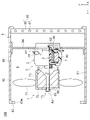
- FIG. 1 is a longitudinal sectional view showing the outdoor unit 8 of Embodiment 1.
- FIG. The outdoor unit 8 constitutes a part of an air conditioner 200 (FIG. 17) such as a room air conditioner.
- the outdoor unit 8 has a housing 80, a blower 6 arranged inside the housing 80, and a heat exchanger 85 arranged on the rear surface of the housing 80.
- the direction of the axis Ax which is the rotation center axis of the motor 3 (described later) of the blower 6, is referred to as the axial direction.
- a circumferential direction centered on the axis Ax is called a “circumferential direction”.
- a radial direction about the axis Ax is referred to as a “radial direction”.
- a cross-sectional view in a cross section parallel to the axial direction is called a "longitudinal cross-sectional view”
- a cross-sectional view in a cross section perpendicular to the axial direction is called a "transverse cross-sectional view".
- the outdoor unit 8 is installed so that the direction of the axis Ax of the motor 3, that is, the axial direction, is orthogonal to the direction of gravity.
- the axial direction of the motor 3 is also called the Y direction or the front-rear direction.
- the gravitational direction is also referred to as the Z direction or vertical direction.
- a direction orthogonal to the Y direction in the horizontal plane is called an X direction.
- the housing 80 has a bottom plate 81, a top plate 82, and a pair of side plates (not shown).
- the bottom plate 81, the top plate 82 and the side plates are all made of sheet metal, for example.
- a front panel 83 is attached to the front surface of the housing 80 .
- An opening 83a is formed in the front panel 83, and a grill (not shown) is fitted therein.
- a support plate 84 extending in the Z direction is fixed to the bottom plate 81 and the top plate 82 of the housing 80 .
- the support plate 84 is made of sheet metal, and the motor 3 of the blower 6 is fixed with screws 48 .
- the support plate 84 holds the blower 6 so that the axial direction of the motor 3 is horizontal.
- the back of the housing 80 is open, and a heat exchanger 85 is arranged on the back side of the blower 6 .
- the heat exchanger 85 has a plurality of fins 86 extending in the Z direction and a plurality of heat transfer tubes 87 extending in the X direction through these fins 86 . Heat is exchanged between the refrigerant flowing inside the heat transfer tubes 87 and the air passing between the fins 86 .
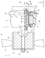
- FIG. 2 is a longitudinal sectional view showing the blower 6. As shown in FIG.
- the blower 6 has a motor 3 and blades 7 rotated by the motor 3 .
- the motor 3 has a rotor 5 having a shaft 60 and a stator 1 radially surrounding the rotor 5 .
- the central axis of the shaft 60 is the above-described axis Ax.
- the motor 3 has a molded resin portion 40 as a resin portion covering the stator 1 .
- the mold resin portion 40 is made of thermosetting resin such as unsaturated polyester resin.
- An unsaturated polyester resin is, for example, BMC (Bulk Molding Compound).
- a molded stator 2 is configured by the stator 1 and the molded resin portion 40 .
- the molded resin portion 40 has an opening 41 on one side in the axial direction and a bearing holding portion 42 on the other side.
- the opening 41 is positioned forward, and the bearing holding portion 42 is positioned rearward.
- the rotor 5 is inserted into the hollow portion inside the molded stator 2 through the opening 41 .
- the shaft 60 axially protrudes from the opening 41 of the molded stator 2 .
- a blade portion 7 is attached to the tip portion of the shaft 60 . Therefore, the side from which the shaft 60 protrudes is called the "load side”, and the opposite side is called the "anti-load side”.
- a bracket 63 is attached to the opening 41 of the mold resin portion 40 .
- a first bearing 61 that supports the shaft 60 is held by the bracket 63 .
- a second bearing 62 that supports the shaft 60 is held in the bearing holding portion 42 of the mold resin portion 40 .
- the molded resin portion 40 has mounting legs 47 projecting radially outward.
- a plurality of mounting legs 47 are formed at regular intervals in the circumferential direction.
- the number of mounting legs 47 is, for example, four.
- the mounting legs 47 are fixed to the support plate 84 of the outdoor unit 8 with screws 48 (FIG. 1).
- a circuit board 43 is arranged on the anti-load side of the stator 1 .
- the circuit board 43 is a printed board on which elements such as power transistors for driving the motor 3 and magnetic sensors for detecting the rotational position of the rotor 5 are mounted.
- a lead wire 44 is wired to the circuit board 43 .
- the lead wire 44 is led out of the molded stator 2 from a lead wire outlet member 45 attached to the outer peripheral portion of the molded resin portion 40 .
- a heat dissipation member 46 is desirably arranged on the anti-load side of the circuit board 43 .
- the heat radiating member 46 is made of metal with high thermal conductivity such as aluminum. A part of the heat dissipation member 46 is exposed from the mold resin portion 40 . Heat generated by the stator 1 and the circuit board 43 is radiated to the outside through the heat radiating member 46 .
- the stator 1 may be fixed to a metal shell. Specifically, the stator 1 may be fixed inside a cylindrical shell containing iron (Fe) as a main component by shrink fitting.
- Fe iron
- the shaft 60 is made of metal such as iron. Shaft 60 is rotatably supported by a first bearing 61 held by bracket 63 and a second bearing 62 held by bearing holding portion 42 .
- the vane portion 7 has a hub 72 fixed to the shaft 60 and a plurality of vanes 71 provided on the outer circumference of the hub 72 .
- the hub 72 is a bottomed cylindrical member centered on the axis Ax, and a plurality of ribs 73 are formed on the inner peripheral side thereof.
- the vanes 7 are made of, for example, polypropylene (PP) containing glass fibers.
- the hub 72 is formed with a through hole through which the threaded portion 65 formed at the tip of the shaft 60 passes.
- the hub 72 is fixed to the shaft 60 by attaching a nut 75 to the threaded portion 65 of the shaft 60 .
- the blades 71 are provided on the outer circumference of the hub 72 at regular intervals in the circumferential direction.
- the number of blades 71 is, for example, three, but may be two or more.
- FIG. 3 is a cross-sectional view showing the motor 3. As shown in FIG.
- the motor 3 has a rotor 5 and an annular stator 1 surrounding the rotor 5, as described above. A gap of 0.4 to 0.7 mm is provided between the rotor 5 and the stator 1 .
- the motor 3 is an IPM (Interior Permanent Magnet) motor in which a permanent magnet 55 is embedded in the rotor 5 .
- FIG. 4 is a sectional view showing the rotor 5.
- FIG. The rotor core 50 is an annular member centered on the axis Ax.
- the rotor core 50 is formed by laminating a plurality of electromagnetic steel sheets in the axial direction and fixing them by caulking or the like.
- the plate thickness of the electromagnetic steel plate is, for example, 0.2 mm to 0.5 mm. It should be noted that the rotor core 50 is not limited to a laminate of electromagnetic steel sheets, and a resin core obtained by mixing a soft magnetic material and a resin may be used.
- the rotor core 50 has a plurality of magnet insertion holes 51 along its outer circumference 50a.
- the magnet insertion holes 51 are arranged at equal intervals in the circumferential direction and at equal distances from the axis Ax.
- the number of magnet insertion holes 51 is ten here.
- the magnet insertion hole 51 extends linearly in a direction orthogonal to a radial straight line passing through the center in the circumferential direction.
- the magnet insertion hole 51 is not limited to such a shape, and may extend in a V shape, for example.
- flux barriers 52 which are holes, are formed.
- a thin portion is formed between the flux barrier 52 and the outer circumference of the rotor core 50 .
- the thickness of the thin portion is desirably the same as the plate thickness of the electromagnetic steel sheets forming the rotor core 50 .
- a permanent magnet 55 is inserted into each magnet insertion hole 51 .
- the permanent magnet 55 has a flat plate shape, and has a rectangular cross-sectional shape perpendicular to the axial direction.
- the permanent magnet 55 is composed of a rare earth magnet. More specifically, permanent magnet 55 is composed of a neodymium sintered magnet containing neodymium (Nd), iron (Fe) and boron (B).
- Permanent magnets 55 adjacent in the circumferential direction are arranged with their magnetic pole surfaces having opposite polarities directed toward the outer circumference 50 a of the rotor core 50 .
- One permanent magnet 55 constitutes one magnetic pole P.
- the number of poles of the rotor 5 is ten here. However, the number of poles of the rotor 5 is not limited to ten, and may be two or more. Between the magnetic poles P adjacent to each other, an interpolar portion M is formed.
- one permanent magnet 55 is arranged in one magnet insertion hole 51 here, two or more permanent magnets 55 may be arranged in one magnet insertion hole 51 . In that case, two or more permanent magnets 55 arranged in one magnet insertion hole 51 constitute one magnetic pole P.
- the outer circumference 50a of the rotor core 50 has a shape in which the radius of the rotor core 50 is maximized at the pole center of each magnetic pole P and minimized at the inter-polar portion M, that is, a so-called flower circle shape.
- the outer circumference 50a of the rotor core 50 is not limited to the flower circle shape, and may be, for example, circular.
- a plurality of holes 53 are formed at regular intervals in the circumferential direction.
- the hole portions 53 are formed radially inside the five magnet insertion holes 51 .
- An arcuate protruding portion 50c extending along the periphery of the hole portion 53 is formed on the inner periphery 50b of the rotor core 50 .
- the projecting portion 50c functions as a rotation stop for the rotor core 50 with respect to the resin portion 56, which will be described later.
- the inner circumference 50b of the rotor core 50 does not necessarily have to form the projecting portion 50c.
- a crimped portion 54 for fixing the electromagnetic steel plates forming the rotor core 50 is formed.
- five crimped portions 54 are provided here, the number and arrangement of the crimped portions 54 are arbitrary.
- a nonmagnetic resin portion 56 is provided between the shaft 60 and the rotor core 50 .
- Resin portion 56 connects shaft 60 and rotor core 50 .
- the resin portion 56 is made of, for example, thermoplastic resin such as polybutylene terephthalate (PBT).
- PBT polybutylene terephthalate
- a shaft 60 axially penetrates through the center of the resin portion 56 .
- a hollow portion or a rib may be formed in the resin portion 56 .
- a sensor magnet 58 is arranged on the anti-load side of the rotor core 50 .
- the sensor magnet 58 is held by the resin portion 56 .
- the magnetic field of the sensor magnet 58 is detected by a magnetic sensor mounted on the circuit board 43, whereby the rotational position of the rotor 5 is detected.
- the shaft 60 may be fitted into the center hole of the rotor core 50 without providing the resin portion 56 .
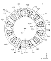
- FIG. 5 is a cross-sectional view showing the stator 1.
- the stator 1 has a stator core 10 and coils 15 wound around the stator core 10 .
- the outer circumference of the stator 1 is covered with a mold resin portion 40 (FIG. 3).
- the stator core 10 is made by laminating a plurality of magnetic steel sheets in the axial direction and fixing them by caulking or the like.
- the plate thickness of the electromagnetic steel plate is, for example, 0.2 mm to 0.5 mm.
- the stator core 10 has an annular core back 11 centered on the axis Ax and a plurality of teeth 12 extending radially inward from the core back 11 .
- the teeth 12 are arranged at regular intervals in the circumferential direction.
- the number of teeth 12 is twelve here, but is not limited to twelve.
- a tooth crest 121 is formed on the radially inner side of the tooth 12 .
- a tooth crest 121 of the tooth 12 faces the outer circumference of the rotor 5 .
- Slots 13 for accommodating coils 15 are formed between teeth 12 adjacent in the circumferential direction.
- the core back 11 has an outer circumference 111 covered with the mold resin portion 40 ( FIG. 2 ) and an inner circumference 112 facing the slot 13 .
- the stator core 10 is provided with an insulating portion 16 .
- the insulating portion 16 is obtained by integrally molding a resin with the stator core 10 or by assembling a preformed resin molding to the stator core 10 .
- the insulating portion 16 is made of resin such as polybutylene terephthalate (PBT), polyphenylene sulfide (PPS), liquid crystal polymer (LCP), and polyethylene terephthalate (PET). Also, the insulating portion 16 may be formed of an insulating film having a thickness of 0.035 mm to 0.4 mm.
- the coil 15 is wound around the tooth 12 via the insulating portion 16 .
- the coil 15 has a conductor made of copper or aluminum and an insulating coating covering the conductor.
- the stator core 10 is formed by connecting split cores 100 each including one tooth 12 .
- the number of split cores 100 is the same as the number of teeth 12, which is 12 here.
- FIG. 6(A) is a diagram showing the split core 100.
- the split core 100 has one tooth 12 and a part of the core back 11 radially outside of the one tooth 12, that is, an arcuate portion.
- Divided surfaces 110 are formed on both circumferential sides of the arcuate portion of the core back 11 .
- the dividing surface 110 extends from the inner circumference 112 to the outer circumference 111 of the core back 11 .
- a plurality of split cores 100 forming stator core 10 ( FIG. 5 ) are fixed to each other by welding at split surfaces 110 .
- Crimped portions 114 and 124 are provided to fix the electromagnetic steel plates that constitute the split core 100 .
- the crimped portion 114 is formed on the core back 11 and the crimped portion 124 is formed on the teeth 12 .
- the number and arrangement of the crimped parts are arbitrary.
- the coil 15 is wound around the teeth 12 of the split core 100 via the insulating portion 16, and then the 12 split cores 100 are annularly combined to form the stator core 10. This simplifies the winding of the coil 15 and improves the winding density.
- the stator core 10 may be composed of a connecting core 101 shown in FIG. 6(B).
- the connecting core 101 has two teeth 12 and a part of the core back 11 on the radially outer side of the two teeth 12, that is, an arcuate portion. That is, the connecting core 101 has a shape in which two split cores 100 shown in FIG. 6(A) are connected.
- a split surface 115 located between the two split cores 100 is formed on the core back 11 of the connecting core 101 .
- the dividing surface 115 extends from the inner periphery 112 toward the outer periphery 111 but does not reach the outer periphery 111 .
- a thin portion 113 is formed between the dividing surface 115 and the outer periphery 111 .
- the connecting core 101 is spread using the thin portion 113 as a fulcrum, and in this state, the coil 15 is wound around the two teeth 12 via the insulating portion 16 .
- the stator core 10 is configured by annularly combining the six connected cores 101 . This simplifies the winding of the coil 15 and improves the winding density.
- a tooth 12 located at the lowest position among the teeth 12 is referred to as a tooth 12A, and a tooth 12 adjacent to this tooth 12A in the circumferential direction is referred to as a tooth 12B.
- Another tooth 12 adjacent to the tooth 12A in the circumferential direction is referred to as a tooth 12C. All of the teeth 12A, 12B, 12C are positioned below the axis Ax. Teeth 12A are also referred to as first teeth, and teeth 12B are also referred to as second teeth.
- the uppermost tooth 12 among the teeth 12 is referred to as a tooth 12D, and the tooth 12 adjacent to this tooth 12D in the circumferential direction is referred to as a tooth 12E.
- Another tooth 12 adjacent to the tooth 12D in the circumferential direction is referred to as a tooth 12F. All of the teeth 12D, 12E, 12F are positioned above the axis Ax.
- a non-magnetic portion 21 is provided between a portion positioned radially outward of the teeth 12A and a portion positioned radially outward of the teeth 12B.
- the non-magnetic portion 21 is provided at the portion connecting the teeth 12A and 12B.
- the non-magnetic portion 21 is also called a first non-magnetic portion.
- the non-magnetic portion 21 is configured by arranging a non-magnetic material in a hollow portion formed in the core back 11 .
- the non-magnetic material is, for example, non-magnetic resin, which is the same resin as the mold resin portion 40 here.
- the non-magnetic material is not limited to resin, and may be air, for example.
- the non-magnetic portion 21 has a width W1 in the circumferential direction and a length T1 in the radial direction.
- the nonmagnetic portion 21 preferably extends from the inner periphery 112 to the outer periphery 111 of the core back 11 .
- the length T1 of the non-magnetic portion 21 is preferably the same as the distance from the inner periphery 112 to the outer periphery 111 of the core back 11 .
- Embodiment 1 Next, the operation of Embodiment 1 will be described.
- the magnetic flux emitted from the permanent magnets 55 of the rotor 5 flows into the stator 1 through the air existing between the rotor 5 and the stator 1, that is, the air gap.
- the distance between the stator 1 and the rotor 5 is 0.4 to 0.7 mm, preferably constant in the circumferential direction.
- the motor 3 is arranged so that the axial direction, that is, the direction of the axis Ax, is orthogonal to the direction of gravity, the rotor 5 is displaced downward by gravity.
- the space between the stator 1 and the rotor 5 is narrower on the lower side than on the upper side.
- both the gaps G1 and G2 are defined as the gaps between the pole centers of the magnetic poles P and the stator 1 .
- FIG. 7 is a diagram for explaining the flow of magnetic flux in the stator 1 of Embodiment 1.
- FIG. 3 The magnetic flux that has flowed into the teeth 12A from the rotor 5 (FIG. 3) through the air gap flows into the core back 11 and returns from the adjacent teeth 12B to the rotor 5 through the air gap.
- a magnetic path including the teeth 12A and 12B is referred to as a magnetic path R1.
- a magnetic path including the teeth 12D and 12E is referred to as a magnetic path R2.
- the length of the magnetic path R1 is shorter than the length of the magnetic path R2 by ⁇ G ⁇ 2. Therefore, the magnetic flux flows more easily in the magnetic path R1 than in the magnetic path R2. there is a possibility.
- the core back 11 is provided with the non-magnetic portion 21 at the portion where the teeth 12A and 12B are connected. Since the non-magnetic portion 21 has a high magnetic resistance like the air gap, the magnetic resistance in the magnetic path R1 can be increased and the magnetic flux flowing through the magnetic path R1 can be reduced.
- the increase in the magnetic attractive force in the region where the distance between the stator 1 and the rotor 5 is narrow can be mitigated by the decrease in the magnetic flux flowing through the magnetic path R1.
- the magnetic attraction force between the stator 1 and the rotor 5 can be made uniform in the circumferential direction, whirling of the rotor 5 can be suppressed, and noise can be reduced.
- the width W1 of the non-magnetic portion 21 in the circumferential direction is preferably twice the difference ⁇ G between the gaps G1 and G2 between the stator 1 and the rotor 5. That is, the magnetic flux from the rotor 5 passes through the air gap when flowing into the teeth 12 and also passes through the air gap when returning from the adjacent teeth 12 to the rotor 5 . If the width W1 of the non-magnetic portion 21 is twice the difference ⁇ G between the intervals G1 and G2, the length of the non-magnetic portion in the magnetic path R1 and the length of the non-magnetic portion in the magnetic path R2 can be matched, The magnetic attraction force between the stator 1 and the rotor 5 can be made even more uniform.
- the difference ⁇ G between the gaps G1 and G2 is 0.005 to 0.05 mm, so the width W1 of the non-magnetic portion 21 is preferably 0.01 to 0.1 mm. In other words, it is desirable that 0.01 mm ⁇ W1 ⁇ 0.1 mm.
- the lowermost tooth 12 is the tooth 12A
- the adjacent tooth 12 is the tooth 12B. Teeth 12 may be used.
- the axial direction of the motor 3 is perpendicular to the direction of gravity.
- the axial direction of the motor 3 does not necessarily have to be perpendicular to the direction of gravity. It should be crossed with the direction.
- the stator core 10 has the core back 11 and the plurality of teeth 12, and the plurality of teeth 12 has the teeth 12A and 12B adjacent to each other below the axis line Ax. .
- a nonmagnetic portion 21 is provided in a portion of the core back 11 that connects the teeth 12A and 12B.
- the magnetic flux flowing through the magnetic path R1 including the teeth 12A and 12B on the lower side can be reduced, and an increase in the magnetic attractive force due to the narrow gap between the stator 1 and the rotor 5 can be suppressed.
- the magnetic attraction force between the stator 1 and the rotor 5 can be made uniform in the circumferential direction, whirling of the rotor 5 can be suppressed, and noise can be reduced.
- the non-magnetic portion 21 is provided at a portion connecting the lowermost tooth 12A and the adjacent tooth 12B among the teeth 12 of the stator core 10, the gap between the stator 1 and the rotor 5 is reduced.
- the magnetic attraction force can be effectively uniformed.
- the non-magnetic portion 21 extends from the inner circumference 112 to the outer circumference 111 of the core back 11, the magnetic flux flowing through the magnetic path R1 including the teeth 12A and 12B can be effectively reduced. It is possible to more effectively equalize the magnetic attraction force between.
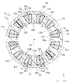
- FIG. 8 is a cross-sectional view showing stator 1A of the second embodiment.
- a nonmagnetic portion 22 is provided above the axis line Ax.
- the non-magnetic portion 22 is also called a second non-magnetic portion.
- the non-magnetic portion 22 is formed in the core back 11 between a portion located radially outside the teeth 12D and a portion located radially outside the teeth 12E. In other words, in the core back 11, the non-magnetic portion 22 is provided at the portion connecting the teeth 12D and 12E.
- the tooth 12D is also called the third tooth
- the tooth 12E is also called the fourth tooth.
- the non-magnetic portion 22 is configured by arranging a non-magnetic material in a hollow portion formed in the core back 11 .
- the non-magnetic material is, for example, non-magnetic resin, which is the same resin as the mold resin portion 40 here.
- the non-magnetic material is not limited to resin, and may be air, for example.
- the nonmagnetic portion 22 has a width W2 in the circumferential direction.
- a circumferential width W1 of the non-magnetic portion 21 is wider than a circumferential width W2 of the non-magnetic portion 22 .
- the non-magnetic portion 22 is preferably formed from the inner circumference 112 to the outer circumference 111 of the core back 11 .
- the non-magnetic portion 22 is positioned in the magnetic path R2 including the teeth 12D, 12E. Therefore, the magnetic flux flowing through the magnetic path R ⁇ b>2 is reduced by the non-magnetic portion 22 .
- the width W2 of the nonmagnetic portion 22 is narrower than the width W1 of the nonmagnetic portion 21, the magnetic resistance in the magnetic path R2 is lower than the magnetic resistance in the magnetic path R1.
- the increase in the magnetic attraction force in the region where the distance between the stator 1A and the rotor 5 is narrow can be mitigated by the decrease in the magnetic flux flowing through the magnetic path R1.
- the magnetic attraction force between the stator 1A and the rotor 5 can be made uniform, and noise can be reduced.
- This second embodiment is also applicable to the case where the mold resin enters between the split cores 100 including the teeth 12D and 12E during the manufacturing process of the molded stator 2 and the non-magnetic portion 22 is formed unintentionally. be able to.
- the non-magnetic portion 21 having a sufficient width is provided in the portion connecting the teeth 12A and 12B, the non-magnetic portion 22 is formed in the portion connecting the teeth 12D and 12E. Even if there is, it is possible to suppress an increase in the magnetic attraction force in a region where the distance between the stator 1A and the rotor 5 is narrow.
- the nonmagnetic portion of the magnetic path R1 is It is possible to match the length with the length of the non-magnetic portion of the magnetic path R2. Thereby, the magnetic attraction force between the stator 1A and the rotor 5 can be made more uniform.
- the width W1 of the non-magnetic portion 21 is longer than the width W2 of the non-magnetic portion 22 by 0.01 to 0.1 mm. is desirable. In other words, it is desirable that W2+0.01 mm ⁇ W1 ⁇ W2+0.1 mm.
- the motor of the second embodiment is configured in the same manner as the motor 3 of the first embodiment.
- the non-magnetic portion 21 is provided at the portion connecting the teeth 12A and 12B, and the non-magnetic portion 22 is provided at the portion connecting the teeth 12D and 12E. ing.
- a circumferential width W1 of the non-magnetic portion 21 is wider than a circumferential width W2 of the non-magnetic portion 22 .
- the magnetic flux flowing through the magnetic path R1 including the lower teeth 12A and 12B can be reduced more than the magnetic flux flowing through the magnetic path R2 including the upper teeth 12D and 12E. It is possible to suppress an increase in the magnetic attraction force in a narrow area. Thereby, the magnetic attraction force between the stator 1A and the rotor 5 can be made uniform, and noise can be reduced.
- FIG. 9 is a cross-sectional view showing stator 1B of the third embodiment.
- the core back 11 of the stator 1B of the third embodiment is provided with a nonmagnetic portion 23 below the axis line Ax in addition to the nonmagnetic portions 21 and 22 described in the second embodiment.
- the non-magnetic portion 23 is also called a third non-magnetic portion.
- the non-magnetic portion 23 is formed in the core back 11 between a portion located radially outward of the teeth 12A and a portion located radially outward of the teeth 12C. In other words, in the core back 11, the non-magnetic portion 23 is provided at the portion connecting the teeth 12A and 12C. Teeth 12C are also referred to as fifth teeth.
- the non-magnetic portion 23 is configured by arranging a non-magnetic material in a hollow portion formed in the core back 11 .
- the non-magnetic material is, for example, non-magnetic resin, which is the same resin as the mold resin portion 40 here.
- the non-magnetic material is not limited to resin, and may be air, for example.
- the non-magnetic portions 21, 22, 23 have circumferential widths W1, W2, W3.
- the widths W1, W2, W3 of the non-magnetic portions 21, 22, 23 satisfy W1>W2 and W3>W2.
- it is desirable that the non-magnetic portion 23 is formed from the inner circumference 112 to the outer circumference 111 of the core back 11 .
- the magnetic flux that has flowed from the rotor 5 to the teeth 12A splits into the teeth 12B and 12C in the core back 11 and returns to the rotor 5 from the teeth 12B and 12C. That is, a magnetic path R1 including teeth 12A and teeth 12B and a magnetic path R3 including teeth 12A and teeth 12C are formed.
- the magnetic flux flowing through the magnetic path R1 passes through the non-magnetic portion 21, and the magnetic flux flowing through the magnetic path R3 passes through the non-magnetic portion 23. Therefore, the magnetic resistance in the magnetic paths R1 and R3 increases, and the magnetic flux flowing through them decreases.
- the magnetic flux that has flowed from the rotor 5 to the teeth 12D is split between the teeth 12E and 12F in the core back 11 and returns to the rotor 5 from the teeth 12E and 12F. That is, a magnetic path R2 including teeth 12D and teeth 12E and a magnetic path R4 including teeth 12D and teeth 12F are formed.
- the magnetic flux flowing through the magnetic path R2 passes through the non-magnetic portion 22.
- the magnetic flux flowing through the magnetic path R4 does not pass through the non-magnetic portion within the core back 11 . Therefore, the magnetic resistance in the magnetic path R2 increases, but the magnetic resistance in the magnetic path R4 does not increase.
- the magnetic resistance in the magnetic path R2 is lower than the magnetic resistance in the magnetic path R1 as described in the second embodiment. Moreover, since the non-magnetic portion of the magnetic path R4 is only the air gap, the magnetic resistance in the magnetic path R4 is the lowest.
- the magnetic flux flowing through the magnetic paths R1 and R3 is less than the magnetic flux flowing through the magnetic paths R2 and R4. That is, by providing the non-magnetic portions 21, 22, 23, the magnetic flux flowing through the magnetic paths R1, R3 is reduced more than the magnetic flux flowing through the magnetic paths R2, R4.
- the increase in the magnetic attractive force in the region where the distance between the stator 1B and the rotor 5 is narrow can be mitigated by the decrease in the magnetic flux flowing through the magnetic paths R1 and R3.
- the magnetic attraction force between the stator 1B and the rotor 5 can be made uniform, and noise can be reduced.
- widths W1, W2, and W3 of the nonmagnetic portions 21, 22, and 23 satisfy W1>W2 and W3>W2 here, at least one of W1>W2 and W3>W2 is satisfied. If so, the effect of equalizing the magnetic attraction force between the stator 1B and the rotor 5 can be obtained to some extent.
- the motor of the third embodiment is configured in the same manner as the motor of the second embodiment.
- the stator core 10 includes the teeth 12A, 12B, and 12C that are circumferentially adjacent below the axis Ax, and the teeth 12D that are circumferentially adjacent above the axis Ax. 12E and 12F.
- the core back 11 is provided with a non-magnetic portion 21 at a portion connecting the teeth 12A and 12B, a non-magnetic portion 23 at a portion connecting the teeth 12A and 12C, and a non-magnetic portion 23 at a portion connecting the teeth 12D and 12E.
- a magnetic portion 22 is provided. Circumferential widths W1, W2 and W3 of the non-magnetic portions 21, 22 and 23 satisfy at least one of W1>W2 and W3>W2.
- the magnetic flux flowing through the magnetic paths R1, R3 including the lower teeth 12A, 12B, 12C can be made smaller than the magnetic flux flowing through the magnetic paths R2, R4 including the upper teeth 12D, 12E, 12F. It is possible to suppress an increase in magnetic attractive force in a region where the distance between 1B and rotor 5 is narrow. Thereby, the magnetic attraction force between the stator 1B and the rotor 5 can be made uniform, and noise can be reduced.
- FIG. 10 is a cross-sectional view showing stator 1C of the fourth embodiment.
- the core back 11 of the stator 1C of the fourth embodiment is provided with the nonmagnetic portions 21 and 22 as described in the second embodiment, but the radial lengths of the nonmagnetic portions 21 and 22 are different from each other. .
- the non-magnetic portion 21 as the first non-magnetic portion is formed in the portion of the core back 11 that connects the teeth 12A and 12B.
- a non-magnetic portion 22 as a second non-magnetic portion is formed in a portion of the core back 11 that connects the teeth 12D and 12E.
- the radial length T1 of the nonmagnetic portion 21 is longer than the radial length T2 of the nonmagnetic portion 22 .
- the circumferential widths W1 and W2 of the non-magnetic portions 21 and 22 are the same.
- the area S1 of the non-magnetic portion 21 is larger than the area S2 of the non-magnetic portion 22 .
- the area of the non-magnetic portion refers to the area of the plane perpendicular to the axis Ax.
- a thin portion 116 is formed between the nonmagnetic portion 21 and the outer periphery 111
- a thin portion 117 is formed between the nonmagnetic portion 22 and the outer periphery 111 . Since the radial length T2 of the nonmagnetic portion 22 is shorter than the radial length T1 of the nonmagnetic portion 21 , the radial width of the thin portion 117 is wider than the radial width of the thin portion 116 .
- the magnetic flux flowing through the magnetic path R1 including the teeth 12A, 12B passes through the thin portion 116.
- Magnetic flux flowing through the magnetic path R2 including the teeth 12D and 12E passes through the thin portion 117.
- the radial width of the thin portion 117 is wider than the radial width of the thin portion 116, magnetic saturation is less likely to occur in the magnetic path R2 than in the magnetic path R1. That is, the reluctance in the magnetic path R2 is lower than the reluctance in the magnetic path R1.
- the increase in the magnetic attraction force in the region where the distance between the stator 1C and the rotor 5 is narrow can be mitigated by the decrease in the magnetic flux flowing through the magnetic path R1.
- the magnetic attraction force between the stator 1C and the rotor 5 can be made uniform, and noise can be reduced.
- widths W1 and W2 of the non-magnetic portions 21 and 22 in the circumferential direction are the same, if the area S1 of the non-magnetic portion 21 is larger than the area S2 of the non-magnetic portion 22, the widths W1 and W2 are different. One may be wider than the other.
- the motor of the fourth embodiment is configured in the same manner as the motor of the second embodiment.
- the non-magnetic portion 21 is provided at the portion connecting the teeth 12A and 12B, and the non-magnetic portion 22 is provided at the portion connecting the teeth 12D and 12E. ing.
- the area S1 of the non-magnetic portion 21 is larger than the area S2 of the non-magnetic portion 22 in the circumferential direction.
- the magnetic flux flowing through the magnetic path R1 including the lower teeth 12A and 12B can be reduced more than the magnetic flux flowing through the magnetic path R2 including the upper teeth 12D and 12E. It is possible to suppress an increase in the magnetic attraction force in a narrow area. Thereby, the magnetic attraction force between the stator 1C and the rotor 5 can be made uniform, and noise can be reduced.
- FIG. 11 is a cross-sectional view showing a stator 1D according to the fifth embodiment.
- the core back 11 of the stator 1D of the fifth embodiment is provided with a non-magnetic portion 23 below the axis line Ax.
- a non-magnetic portion 23 as a third non-magnetic portion is formed in a portion of the core back 11 that connects the teeth 12A and 12C.
- the non-magnetic portion 23 is configured by arranging a non-magnetic material in the hollow portion formed in the core back 11 as described in the third embodiment.
- the non-magnetic portions 21 and 22 are as described in the fourth embodiment.
- the radial lengths T1, T2 and T3 of the non-magnetic portions 21, 22 and 23 satisfy T1>T2 and T3>T2.
- the circumferential widths W1, W2, W3 of the non-magnetic portions 21, 22, 23 are the same.
- the areas S1, S2 and S3 of the non-magnetic portions 21, 22 and 23 satisfy S1>S2 and S3>S2.
- the area of the non-magnetic portion refers to the area on the plane perpendicular to the axis Ax.
- a thin portion 116 is formed between the non-magnetic portion 21 and the outer periphery 111, a thin portion 117 is formed between the non-magnetic portion 22 and the outer periphery 111, and a non-magnetic portion 23 and the outer periphery 111 are formed.
- a thin portion 118 is formed between the . Since the radial length T2 of the nonmagnetic portion 22 is shorter than the radial lengths T1 and T3 of the nonmagnetic portions 21 and 23, the radial width of the thin portion 116 is wider than the radial width of the thin portions 117 and 118. .
- Magnetic flux flowing through magnetic path R1 including teeth 12A and 12B passes through thin portion 116 on the side of outer periphery 111 of nonmagnetic portion 21, and magnetic flux flowing through magnetic path R3 including teeth 12A and 12C passes through the outer periphery of nonmagnetic portion 23. It passes through the thin portion 118 on the 111 side.
- the magnetic flux flowing through the magnetic path R2 including the teeth 12D and 12E passes through the thin portion 117 on the outer periphery 111 side of the non-magnetic portion 22.
- the magnetic flux flowing through the magnetic path R4 including the teeth 12D and 12F does not pass through the non-magnetic portion within the core back 11. As shown in FIG.
- the magnetic resistance in the magnetic path R2 is lower than the magnetic resistance in the magnetic paths R1 and R3.
- the non-magnetic portion of the magnetic path R4 is only the air gap, the magnetic resistance in the magnetic path R4 is the lowest.
- the magnetic flux flowing through the magnetic paths R1 and R3 is less than the magnetic flux flowing through the magnetic paths R2 and R4. That is, by providing the non-magnetic portions 21, 22, 23, the magnetic flux flowing through the magnetic paths R1, R3 is reduced more than the magnetic flux flowing through the magnetic paths R2, R4.
- the increase in the magnetic attractive force in the region where the distance between the stator 1D and the rotor 5 is narrow can be mitigated by the decrease in the magnetic flux flowing through the magnetic paths R1 and R3.
- the magnetic attraction force between the stator 1D and the rotor 5 can be made uniform, and noise can be reduced.
- widths S1, S2, and S3 of the nonmagnetic portions 21, 22, and 23 satisfy S1>S2 and S3>S2 here, at least one of S1>S2 and S3>S2 is satisfied. If so, the effect of equalizing the magnetic attraction force between the stator 1B and the rotor 5 can be obtained to some extent.
- the radial lengths T1, T2, and T3 of the non-magnetic portions 21, 22, and 23 satisfy T1>T2 and T3>T2, at least T1>T2 and T3>T2 It is sufficient if one is satisfied.
- widths W1, W2 and W3 of the non-magnetic portions 21, 22 and 23 are the same here, at least one of the areas S1 and S3 of the non-magnetic portions 21 and 23 may be larger than the area S2 of the non-magnetic portion 22.
- widths W1, W2, and W3 may not be the same.
- the motor of Embodiment 5 is configured in the same manner as the motor of Embodiment 4.
- the stator core 10 includes the teeth 12A, 12B, and 12C that are circumferentially adjacent below the axis Ax, and the teeth 12D that are circumferentially adjacent above the axis Ax. 12E and 12F.
- the core back 11 is provided with a non-magnetic portion 21 at a portion connecting the teeth 12A and 12B, a non-magnetic portion 23 at a portion connecting the teeth 12A and 12C, and a non-magnetic portion 23 at a portion connecting the teeth 12D and 12E.
- a magnetic portion 22 is provided.
- the areas S1, S2, S3 of the nonmagnetic portions 21, 22, 23 satisfy at least one of S1>S2 and S3>S2.
- the magnetic flux flowing through the magnetic paths R1, R3 including the lower teeth 12A, 12B, 12C can be made smaller than the magnetic flux flowing through the magnetic paths R2, R4 including the upper teeth 12D, 12E, 12F. It is possible to suppress an increase in the magnetic attractive force in a region where the distance between 1D and rotor 5 is narrow. Thereby, the magnetic attraction force between the stator 1D and the rotor 5 can be made uniform, and noise can be reduced.
- FIG. 12 is a cross-sectional view showing stator 1E of the sixth embodiment.
- the shape of the non-magnetic portions 31, 32, 33 of the stator 1E is different from the non-magnetic portions 21, 22, 23 of the fifth embodiment.
- the arrangement of the non-magnetic portions 31, 32, 33 is the same as that of the non-magnetic portions 21, 23, 23 of the fifth embodiment. That is, the non-magnetic portion 31 is formed in a portion of the core back 11 that connects the teeth 12A and 12B. The non-magnetic portion 32 is formed in a portion of the core back 11 that connects the teeth 12D and 12E. The nonmagnetic portion 33 is formed in a portion of the core back 11 that connects the teeth 12A and 12C.
- All of the nonmagnetic portions 31, 32, and 33 have a triangular shape in which the width in the circumferential direction is wider on the inner circumference 112 side of the core back 11 than on the outer circumference 111 side.
- the non-magnetic portions 31 , 32 , 33 are not limited to triangular, and may be trapezoidal, for example, as long as the width in the circumferential direction is narrower on the side of the outer circumference 111 of the core back 11 than on the side of the inner circumference 112 .
- the non-magnetic portion 31 has a width W1 in the circumferential direction.
- the width W1 is the maximum circumferential width of the non-magnetic portion 31, in other words, the width of the bottom of the non-magnetic portion 31, that is, the edge on the inner periphery 112 side.
- the non-magnetic portions 32, 33 have widths W2, W3 in the circumferential direction.
- the widths W1, W2 and W3 of the non-magnetic portions 31, 32 and 33 satisfy W1>W2 and W3>W2.
- the non-magnetic portion 31 has a radial length T1.
- the length T1 is the radial length from the base of the non-magnetic portion 31 to the vertex, that is, the radially outermost point.
- the non-magnetic portions 32, 33 have radial lengths T2, T3.
- the lengths T1, T2 and T3 of the non-magnetic portions 31, 32 and 33 satisfy T1>T2 and T3>T2.
- All of the nonmagnetic portions 31 , 32 , 33 are formed from the inner periphery 112 of the core back 11 toward the outer periphery 111 .
- a thin portion 171 is formed between the non-magnetic portion 31 and the outer periphery 111 .
- a thin portion 172 is formed between the nonmagnetic portion 32 and the outer periphery 111 .
- a thin portion 173 is formed between the non-magnetic portion 33 and the outer periphery 111 .
- the magnetic flux flowing through the magnetic path R1 including the teeth 12A and 12B passes through the thin portion 171 on the side of the outer periphery 111 of the non-magnetic portion 31, and the magnetic flux flowing through the magnetic path R3 including the teeth 12A and 12C passes through the outer periphery of the non-magnetic portion 33. It passes through the thin portion 173 on the 111 side.
- the magnetic flux flowing through the magnetic path R2 including the teeth 12D and 12E passes through the thin portion 172 on the side of the outer periphery 111 of the non-magnetic portion 32, and the magnetic flux flowing through the magnetic path R4 including the teeth 12D and 12F is inside the core back 11. does not pass through the non-magnetic portion.
- the magnetic resistance in the magnetic path R2 is lower than the magnetic resistance in the magnetic paths R1 and R3. Further, since the non-magnetic portion of the magnetic path R4 is only the air gap, the magnetic resistance of the magnetic path R4 is the lowest.
- the magnetic flux flowing through the magnetic paths R1 and R3 including the teeth 12A, 12B and 12C is less than the magnetic flux flowing through the magnetic paths R2 and R4 including the teeth 12D, 12E and 12F. That is, by providing the non-magnetic portions 31, 32, 33, the magnetic flux flowing through the magnetic paths R1, R3 is reduced more than the magnetic flux flowing through the magnetic paths R2, R4.
- the increase in the magnetic attractive force in the region where the distance between the stator 1D and the rotor 5 is narrow can be mitigated by the decrease in the magnetic flux flowing through the magnetic paths R1 and R3.
- the magnetic attraction force between the stator 1E and the rotor 5 can be made uniform, and noise can be reduced.
- the stator core 10 is covered with mold resin such as BMC.
- mold resin such as BMC.
- the widths of the nonmagnetic portions 31 , 32 , 33 are wide on the inner periphery 112 side of the core back 11 . Therefore, if hollow portions having shapes corresponding to the non-magnetic portions 31 , 32 , 33 are formed in the core back 11 , the mold resin is easily filled into the hollow portions from the inner circumference 112 side of the core back 11 . As a result, the non-magnetic portions 31, 32, 33 can be formed with molding resin without gaps.
- widths W1, W2, and W3 of the nonmagnetic portions 31, 32, and 33 satisfy W1>W2 and W3>W2 here, at least one of W1>W2 and W3>W2 is satisfied. If so, the effect of equalizing the magnetic attraction force between the stator 1E and the rotor 5 can be obtained to some extent.
- the radial lengths T1, T2, and T3 of the nonmagnetic portions 31, 32, and 33 satisfy T1>T2 and T3>T2, at least T1>T2 and T3>T2 It is sufficient if one is satisfied.
- the non-magnetic portions 31 and 33 are provided below the axis Ax, and the non-magnetic portion 32 is provided above the axis Ax.
- the non-magnetic portion 31 may be provided as in the first embodiment.
- the motor of Embodiment 6 is configured in the same manner as the motor of Embodiment 5.
- the nonmagnetic portions 31, 32, and 33 have a shape in which the width in the circumferential direction is wider on the inner circumference 112 side of the core back 11 than on the outer circumference 111 side. and the rotor 5, thereby reducing noise and facilitating the formation of the non-magnetic portions 31, 32, 33.
- FIG. 13 is a cross-sectional view showing the stator 1F of Embodiment 7.
- FIG. 13 is a cross-sectional view showing the stator 1F of Embodiment 7.
- the shapes of non-magnetic portions 31, 32, 33 of the stator 1F are different from those in the sixth embodiment.
- the arrangement of the non-magnetic portions 31, 32, 33 is the same as in the sixth embodiment.
- Each of the nonmagnetic portions 31 , 32 , 33 has a triangular shape in which the width in the circumferential direction is wider on the outer circumference 111 side than on the inner circumference 112 side of the core back 11 .
- the non-magnetic portions 31 , 32 , 33 are not limited to triangular, and may be trapezoidal, for example, as long as the circumferential width of the core back 11 is wider on the outer circumference 111 side than on the inner circumference 112 side.
- the non-magnetic portion 31 has a width W1 in the circumferential direction.
- the width W1 is the maximum circumferential width of the nonmagnetic portion 31, in other words, the width of the bottom of the nonmagnetic portion 31, that is, the edge on the outer periphery 111 side.
- the non-magnetic portions 32, 33 have widths W2, W3 in the circumferential direction.
- the widths W1, W2 and W3 of the non-magnetic portions 31, 32 and 33 satisfy W1>W2 and W3>W2.
- the non-magnetic portion 31 has a radial length T1.
- the length T1 is the radial length from the base of the nonmagnetic portion 31 to the vertex, that is, the radially innermost point.
- the non-magnetic portions 32, 33 have radial lengths T2, T3.
- the lengths T1, T2 and T3 of the non-magnetic portions 31, 32 and 33 satisfy T1>T2 and T3>T2.
- All of the nonmagnetic portions 31 , 32 , 33 are formed from the outer circumference 111 toward the inner circumference 112 of the core back 11 .
- a thin portion 181 is formed between the non-magnetic portion 31 and the inner periphery 112 .
- a thin portion 182 is formed between the non-magnetic portion 32 and the inner periphery 112 .
- a thin portion 183 is formed between the non-magnetic portion 33 and the inner periphery 112 .
- the magnetic flux flowing through the magnetic path R1 including the teeth 12A and 12B passes through the thin portion 181 on the inner circumference 112 side of the non-magnetic portion 31, and the magnetic flux flowing through the magnetic path R3 including the teeth 12A and 12C passes through the non-magnetic portion 33. It passes through the thin portion 183 on the inner periphery 112 side.
- the magnetic flux flowing through the magnetic path R2 including the teeth 12D and 12E passes through the thin portion 182 on the inner circumference 112 side of the non-magnetic portion 32.
- the magnetic flux flowing through the magnetic path R4 including the teeth 12D and 12F does not pass through the non-magnetic portion of the core back 11.
- the magnetic resistance in the magnetic path R2 is lower than the magnetic resistance in the magnetic paths R1 and R3. Further, since the non-magnetic portion of the magnetic path R4 is only the air gap, the magnetic resistance of the magnetic path R4 is the lowest.
- the magnetic flux flowing through the magnetic paths R1 and R3 including the teeth 12A, 12B and 12C is less than the magnetic flux flowing through the magnetic paths R2 and R4 including the teeth 12D, 12E and 12F. That is, by providing the non-magnetic portions 31, 32, 33, the magnetic flux flowing through the magnetic paths R1, R3 is reduced more than the magnetic flux flowing through the magnetic paths R2, R4.
- the stator core 10 is covered with mold resin such as BMC.
- mold resin such as BMC.
- the widths of the non-magnetic portions 31 , 32 , 33 are wide on the outer circumference 111 side of the core back 11 . Therefore, if hollow portions having shapes corresponding to the non-magnetic portions 31 , 32 , 33 are formed in the core back 11 , the mold resin is easily filled into the hollow portions from the outer periphery 111 side of the core back 11 . As a result, the non-magnetic portions 31, 32, 33 can be formed with molding resin without gaps.
- widths W1, W2, and W3 of the nonmagnetic portions 31, 32, and 33 satisfy W1>W2 and W3>W2 here, at least one of W1>W2 and W3>W2 is satisfied. If so, the effect of equalizing the magnetic attraction force between the stator 1F and the rotor 5 can be obtained to some extent.
- the radial lengths T1, T2, and T3 of the nonmagnetic portions 31, 32, and 33 satisfy T1>T2 and T3>T2, at least T1>T2 and T3>T2 It is sufficient if one is satisfied.
- the non-magnetic portions 31 and 33 are provided below the axis Ax, and the non-magnetic portion 32 is provided above the axis Ax.
- the non-magnetic portion 31 may be provided as in the first embodiment.
- the motor of Embodiment 7 is configured in the same manner as the motor of Embodiment 6.
- the nonmagnetic portions 31, 32, and 33 have a shape in which the width in the circumferential direction is wider on the outer circumference 111 side than on the inner circumference 112 side of the core back 11, so that the stator 1E and the rotor 5, thereby reducing noise and facilitating the formation of the non-magnetic portions 31, 32, 33.
- FIG. 14 is a cross-sectional view showing the stator 1G of the eighth embodiment.
- a stator 1G of the eighth embodiment differs from that of the first embodiment in that teeth 12A positioned below the axis Ax are shorter than the other teeth 12.
- FIG. 14 is a cross-sectional view showing the stator 1G of the eighth embodiment.
- a stator 1G of the eighth embodiment differs from that of the first embodiment in that teeth 12A positioned below the axis Ax are shorter than the other teeth 12.
- the length of the teeth 12A as the first teeth is shorter than the length of the other teeth 12 of the stator 1G. Therefore, the tooth crest 125 of the tooth 12 ⁇ /b>A is located at a position radially outwardly displaced from the tooth crest 121 of the other teeth 12 .
- the tooth top surface 125 of the tooth 12A is desirably covered with a non-magnetic portion 132 made of a non-magnetic material.
- the non-magnetic portion 132 is preferably a part of the mold resin portion 140 (FIG. 3), for example, but may be made of resin other than the mold resin.
- the tooth crests 121 of the other teeth 12 are exposed.
- the tooth crest surface 125 of the tooth 12A is positioned radially outwardly relative to the tooth crest surface 121 of the other teeth 12, even if the rotor 5 is displaced downward due to its own weight, the rotor 5 and the teeth 12A can be secured to suppress an increase in the magnetic attractive force. As a result, the magnetic attraction force between the stator 1G and the rotor 5 can be made uniform, and noise can be reduced.
- tooth crest 125 of the tooth 12A is displaced radially outward from the tooth crest 121 of the other teeth 12, the tooth crest 125 of the tooth 12A is located above the axis Ax. It suffices if it is displaced radially outward from the tooth crest 121 of the tooth 12 (for example, tooth 12D).
- teeth 12A are the lowermost teeth 12 of the teeth 12 of the stator core 10 here, any teeth below the axis Ax may be used. Further, the tooth crests 125 of the plurality of teeth 12 below the axis Ax may be displaced radially outward from the tooth crests 121 of the other teeth 12 .
- tooth top surface 125 of the tooth 12A is covered with the non-magnetic portion 132 here, the tooth top surface 125 of the tooth 12A may be exposed.
- the tooth crests of the teeth 12 above the axis Ax may be displaced radially outward from the crests 121 of the other teeth 12.
- the difference between the amount of displacement of the tooth crest 125 of the tooth 12A and the amount of displacement of the crest of the tooth 12D is at least twice the difference ⁇ G between the gaps G1 and G2 described in the first embodiment. It is desirable to have
- non-magnetic portion described in the first to eighth embodiments may be added to the stator 1G of the eighth embodiment.
- a non-magnetic portion 21 may be provided at a portion of the core back 11 where the teeth 12A and 12B are connected.
- the teeth 12A positioned below the axis Ax are displaced radially outward from the teeth 12D positioned above the axis Ax. It is possible to suppress non-uniformity of the magnetic attractive force due to the narrower gap with the stator 1G on the lower side. As a result, whirling of the rotor 5 can be suppressed and noise can be reduced.
- the motor 3 described in each embodiment is an IPM motor in which the permanent magnet 55 is embedded in the rotor 5, but may be an SPM (Surface Permanent Magnet) motor in which the permanent magnet is attached to the surface of the rotor 5.
- FIG. 16 is a diagram showing an example of an SPM motor with permanent magnets 59 attached to the surface of the rotor 5A.
- the rotor 5 ⁇ /b>A holds a permanent magnet 59 with a resin portion 57 provided so as to surround the shaft 60 .
- the permanent magnet 59 is, for example, a bond magnet.
- the permanent magnet 59 is an annular magnet centered on the axis Ax and has a plurality of magnetic poles in the circumferential direction.
- a rotor core may also be provided between the shaft 60 and the permanent magnets 59 .
- FIG. 17 is a diagram showing the configuration of an air conditioner 200 to which the motor of each embodiment can be applied.
- the air conditioner 200 has an outdoor unit 8 and an indoor unit 9 .
- the outdoor unit 8 and the indoor unit 9 are connected by a refrigerant pipe 201 .
- the outdoor unit 8 has a blower 6 as an outdoor blower, a compressor 88, a heat exchanger 85, and a decompression device (not shown).
- the configuration of the blower 6 is as described in the first embodiment with reference to FIG.
- a support plate 84 ( FIG. 1 ) that supports the blower 6 is omitted in FIG. 17 .
- the motor 3 (FIG. 1) of the blower 6 the motor 3 described in the first to eighth embodiments and modifications can be used.
- the axial direction of the motor 3 is horizontal, and the blade portion 7 is fixed to the shaft 60 (FIG. 1) of the motor 3 .
- the indoor unit 9 has an air blower 90 as an indoor air blower, a heat exchanger 92 arranged to face the air blower 90, and a housing 93 that houses them.
- the heat exchanger 92 is connected to the compressor 88 of the outdoor unit 8, the heat exchanger 85, and the decompression device through refrigerant pipes 201 to form a refrigerant circuit.
- the blower 90 has blades 91, which are, for example, cross-flow fans, and a motor 3A for driving them.
- the motor 3 described in the first to eighth embodiments and modifications can be used as the motor 3A.
- the axial direction of the motor 3A is horizontal, and the blade portion 91 is fixed to the shaft of the motor 3A.
- the blade portion 91 is rotated by the motor 3A to blow air into the room.
- the air heated when the refrigerant is condensed in the heat exchanger 92 (condenser) is blown into the room by the blower 90 .
- the rotation of the motor 3 of the blower 6 rotates the vanes 7 , which causes the outdoor air to pass through the heat exchanger 85 .
- the refrigerant compressed by the compressor 88 evaporates in the heat exchanger 85 (evaporator)
- the air passing through the heat exchanger 85 loses heat of evaporation and is cooled.
- the cooled air is released outdoors by blowing air from the blower 6 .
- the space between the rotor 5 and the stator 1 may become narrower on the lower side.
- it is possible to suppress the imbalance of the magnetic attraction force between the rotor 5 and the stator 1, so that the whirling of the rotor 5 can be suppressed and the noise can be reduced. can be done.
- Stator 2 Molded Stator 3, 3A Motor 5, 5A Rotor 6 Blower 7 Blade Part 8 Outdoor Unit 9 Indoor Unit 10 Stator Core 11 Core Back 12, 12A, 12B, 12C, 12D, 12E , 12F Teeth 13 Slot 15 Coil 16 Insulating Part 21, 22, 23 Nonmagnetic Part 31, 32, 33 Nonmagnetic Part 40 Mold Resin Part 43 Circuit Board 50 Rotor Core 51 Magnet Insertion Hole 55 Permanent magnet 56 Resin part 57 Resin part 60 Shaft 80 Housing 90 Blower 91 Blade part 100, 101 Split core 110 Split surface 111 Outer periphery 112 Inner periphery 113, 116, 117, 118 Thin wall Part 121, 125 Tooth crest 132 Nonmagnetic part 140 Mold resin part 171, 172, 173 Thin part 181, 182, 183 Thin part 200 Air conditioner.
Landscapes
- Engineering & Computer Science (AREA)
- Power Engineering (AREA)
- Iron Core Of Rotating Electric Machines (AREA)
Priority Applications (2)
| Application Number | Priority Date | Filing Date | Title |
|---|---|---|---|
| PCT/JP2021/026107 WO2023286117A1 (ja) | 2021-07-12 | 2021-07-12 | モータ、送風機および空気調和装置 |
| JP2023534441A JP7536193B2 (ja) | 2021-07-12 | 2021-07-12 | モータ、送風機および空気調和装置 |
Applications Claiming Priority (1)
| Application Number | Priority Date | Filing Date | Title |
|---|---|---|---|
| PCT/JP2021/026107 WO2023286117A1 (ja) | 2021-07-12 | 2021-07-12 | モータ、送風機および空気調和装置 |
Publications (1)
| Publication Number | Publication Date |
|---|---|
| WO2023286117A1 true WO2023286117A1 (ja) | 2023-01-19 |
Family
ID=84919106
Family Applications (1)
| Application Number | Title | Priority Date | Filing Date |
|---|---|---|---|
| PCT/JP2021/026107 Ceased WO2023286117A1 (ja) | 2021-07-12 | 2021-07-12 | モータ、送風機および空気調和装置 |
Country Status (2)
| Country | Link |
|---|---|
| JP (1) | JP7536193B2 (https=) |
| WO (1) | WO2023286117A1 (https=) |
Cited By (1)
| Publication number | Priority date | Publication date | Assignee | Title |
|---|---|---|---|---|
| WO2024201701A1 (ja) * | 2023-03-28 | 2024-10-03 | 三菱電機株式会社 | モータユニット、送風機および空気調和装置 |
Citations (5)
| Publication number | Priority date | Publication date | Assignee | Title |
|---|---|---|---|---|
| JPS6127451U (ja) * | 1984-07-25 | 1986-02-19 | 株式会社富士通ゼネラル | 電動機 |
| JPS63186542A (ja) * | 1987-01-25 | 1988-08-02 | Yunibetsuku:Kk | スラリ−ポンプ用モ−タ |
| JPH09233887A (ja) * | 1996-02-22 | 1997-09-05 | Toyota Motor Corp | モータ |
| JP2008141869A (ja) * | 2006-12-01 | 2008-06-19 | Mitsubishi Electric Corp | 回転電機 |
| JP2013046519A (ja) * | 2011-08-25 | 2013-03-04 | Denso Corp | 回転電機 |
-
2021
- 2021-07-12 JP JP2023534441A patent/JP7536193B2/ja active Active
- 2021-07-12 WO PCT/JP2021/026107 patent/WO2023286117A1/ja not_active Ceased
Patent Citations (5)
| Publication number | Priority date | Publication date | Assignee | Title |
|---|---|---|---|---|
| JPS6127451U (ja) * | 1984-07-25 | 1986-02-19 | 株式会社富士通ゼネラル | 電動機 |
| JPS63186542A (ja) * | 1987-01-25 | 1988-08-02 | Yunibetsuku:Kk | スラリ−ポンプ用モ−タ |
| JPH09233887A (ja) * | 1996-02-22 | 1997-09-05 | Toyota Motor Corp | モータ |
| JP2008141869A (ja) * | 2006-12-01 | 2008-06-19 | Mitsubishi Electric Corp | 回転電機 |
| JP2013046519A (ja) * | 2011-08-25 | 2013-03-04 | Denso Corp | 回転電機 |
Cited By (1)
| Publication number | Priority date | Publication date | Assignee | Title |
|---|---|---|---|---|
| WO2024201701A1 (ja) * | 2023-03-28 | 2024-10-03 | 三菱電機株式会社 | モータユニット、送風機および空気調和装置 |
Also Published As
| Publication number | Publication date |
|---|---|
| JPWO2023286117A1 (https=) | 2023-01-19 |
| JP7536193B2 (ja) | 2024-08-19 |
Similar Documents
| Publication | Publication Date | Title |
|---|---|---|
| WO2020003341A1 (ja) | ロータ、電動機、送風機および空気調和装置 | |
| CN109478837A (zh) | 电动机、送风机以及空气调节机 | |
| JP7536193B2 (ja) | モータ、送風機および空気調和装置 | |
| US20220376569A1 (en) | Rotor, motor, fan, and air conditioner | |
| JP7185048B2 (ja) | 電動機、送風機および空気調和装置 | |
| WO2021171385A1 (ja) | 送風機および空気調和装置 | |
| JP7386965B2 (ja) | 電動機、送風機および空気調和装置 | |
| AU2020431701C1 (en) | Outdoor Unit and Air Conditioner | |
| JP7450783B2 (ja) | コンシクエントポール型ロータ、電動機、ファン、及び空気調和機 | |
| WO2020213601A1 (ja) | モータ、送風機、空気調和装置およびモータの製造方法 | |
| JP7559044B2 (ja) | 電動機、ファン、及び空気調和機 | |
| JP7241958B2 (ja) | 送風機および空気調和装置 | |
| CN115136468B (zh) | 电动机、送风机及空调装置 | |
| WO2023148949A1 (ja) | 電動機及び空気調和機 | |
| WO2024201701A1 (ja) | モータユニット、送風機および空気調和装置 | |
| JP7607790B2 (ja) | ロータ、電動機、送風機および空気調和装置 | |
| WO2025154247A1 (ja) | モータユニット、送風機および空気調和装置 | |
| WO2025126435A1 (ja) | モータユニット、送風機および空気調和装置 | |
| JPH04133650A (ja) | 送風用無刷子電動機 | |
| WO2023148953A1 (ja) | ロータ、電動機、送風機、空気調和装置および電動機の製造方法 | |
| WO2026071012A1 (ja) | 送風機、及び冷凍装置 | |
| WO2025083844A1 (ja) | 回転子、電動機、送風機および空気調和装置 | |
| WO2022180708A1 (ja) | ステータ、電動機、及び空気調和機 | |
| CN117501587A (zh) | 电动机、送风机和空调装置 |
Legal Events
| Date | Code | Title | Description |
|---|---|---|---|
| 121 | Ep: the epo has been informed by wipo that ep was designated in this application |
Ref document number: 21950061 Country of ref document: EP Kind code of ref document: A1 |
|
| WWE | Wipo information: entry into national phase |
Ref document number: 2023534441 Country of ref document: JP |
|
| NENP | Non-entry into the national phase |
Ref country code: DE |
|
| 122 | Ep: pct application non-entry in european phase |
Ref document number: 21950061 Country of ref document: EP Kind code of ref document: A1 |